ew2002 ap 0610 web_svi2ap with remote sensor
TRANSCRIPT
5/8/2018 EW2002 AP 0610 Web_SVI2Ap With Remote Sensor - slidepdf.com
http://slidepdf.com/reader/full/ew2002-ap-0610-websvi2ap-with-remote-sensor 1/160
Instruction Ma
EW2002
06/10 R
SVI®
II AP
Digital Positioner
With Remote Position Sensor
Putting You In Control
5/8/2018 EW2002 AP 0610 Web_SVI2Ap With Remote Sensor - slidepdf.com
http://slidepdf.com/reader/full/ew2002-ap-0610-websvi2ap-with-remote-sensor 2/160
Warranty
Items sold by Dresser, ® Inc. are warranted to be free from defects in materials and workmanship fo
period of one year from the date of shipment provided said items are used according to Dresser
recommended usages. Dresser, Inc. reserves the right to discontinue manufacture of any product
change product materials, design or specifications without notice.
This instruction manual applies to the following instruments and approved software: SVI ® II AP
Positioner and ValVue ® software.
The SVI II AP series positioners are warranted for use only with interface software approved by
Dresser, Inc. Consult Masoneilan Dresser factory locations for approved software listing.
About this Guide
This Instruction Manual applies to the following instruments and approved software:
q SVI II AP -2 through SVI II AP -3
q - with Firmware version 3.1.1, 3.1.2 or 3.2.1
q - with ValVue ® version 2.4 or greater
q - with AMS ® ValVue ® SNAP-ON ® version 2.4 or greater
q with ValVue PRM Pug-in
q - with Model HH375 HART ® Communicator with DD published for SVI II AP
The information in this manual is subject to change without prior notice.
The information contained in this manual, in whole or part, shall not be transcribed or copied with
Masoneilan’s written permission.
In no case does this manual guarantee the merchantability of the positioner or the software or its
adaptability to a specific client needs.
Please report any errors or questions about the information in this manual to your local supplier o
visit www.masoneilan.com.
Copyright
All software is the intellectual property of Dresser, Inc.
The complete design and manufacture is the intellectual property of Dresser, Inc.
Masoneilan®, FVP®, SVI®, and ValVue® are registered trademarks of Dresser, Inc. All information
contained herein is believed to be accurate at the time of publication and is subject to change with
notice.
Copyright 2010 by Dresser, Inc. All rights reserved.
PN 055201-241 Rev. D
5/8/2018 EW2002 AP 0610 Web_SVI2Ap With Remote Sensor - slidepdf.com
http://slidepdf.com/reader/full/ew2002-ap-0610-websvi2ap-with-remote-sensor 3/160
i
Safety Information
This section provides safety information including safety symbols that are used on the SVI II
AP and the safety symbol definition.
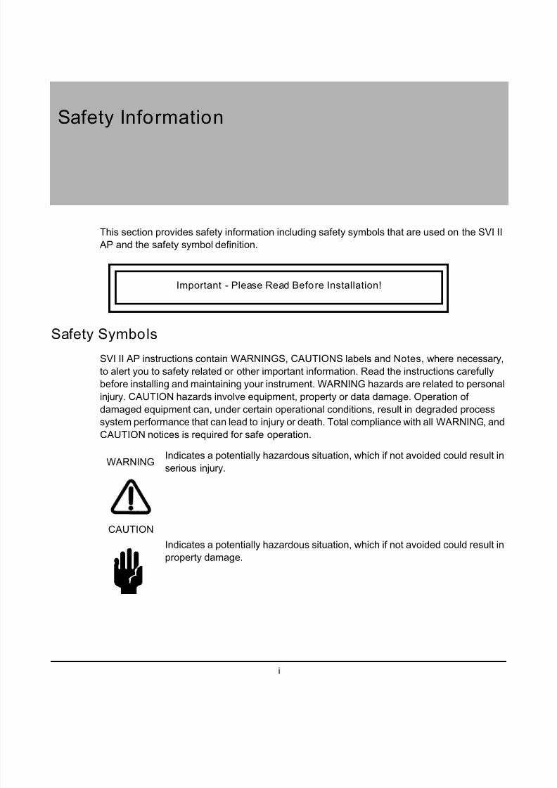
Safety Symbols
SVI II AP instructions contain WARNINGS, CAUTIONS labels and Notes, where necessary,
to alert you to safety related or other important information. Read the instructions carefully
before installing and maintaining your instrument. WARNING hazards are related to personal
injury. CAUTION hazards involve equipment, property or data damage. Operation of
damaged equipment can, under certain operational conditions, result in degraded processsystem performance that can lead to injury or death. Total compliance with all WARNING, and
CAUTION notices is required for safe operation.
Indicates a potentially hazardous situation, which if not avoided could result in
serious injury.
Indicates a potentially hazardous situation, which if not avoided could result in
property damage.
Important - Please Read Before Installation!
WARNING
CAUTION

5/8/2018 EW2002 AP 0610 Web_SVI2Ap With Remote Sensor - slidepdf.com
http://slidepdf.com/reader/full/ew2002-ap-0610-websvi2ap-with-remote-sensor 4/160
SVI II AP Instruction Manual
ii
D R
A F T
6 / 8 / 1 0
Masoneilan Dresser
Indicates important facts and conditions.
SVI II AP Product Safety
The SVI II AP positioner is intended for use with industrial compressed air or, natural gas
systems only.
NOTE Installations using natural gas are Zone 0 or Div 1installations.
Ensure that an adequate pressure relief provision is installed when the application of
system supply pressure could cause peripheral equipment to malfunction. Installationmust be in accordance with local and national compressed air and instrumentation codes.
Products certified as explosion proof or flame proof equipment or for use in intrinsically
safe installations MUST BE:
q Installed, put into service, used and maintained in compliance with national and
local regulations and in accordance with the recommendations contained in the
relevant standards concerning potentially explosive atmospheres.
q Used only in situations that comply with the certification conditions shown in this
document and after verification of their compatibility with the zone of intended use
and the permitted maximum ambient temperature.
q Installed, put into service and maintained by qualified and competent professionals
who have undergone suitable training for instrumentation used in areas with
potentially explosive atmospheres.
Before using these products with fluids other than air or for non-industrial applications,
consult Dresser, Inc. This product is not intended for use in life support systems.
WARNING Under certain operating conditions, the use of damaged instruments could cause a degradation of the performance of the system, which can lead to personal injury or death.
Use only genuine replacement parts which are provided by the manufacturer, to
guarantee that the products comply with the essential safety requirements of the
European Directives.
Changes to specifications, structure, and components used may not lead to the revision
of this manual unless such changes affect the function and performance of the product.

5/8/2018 EW2002 AP 0610 Web_SVI2Ap With Remote Sensor - slidepdf.com
http://slidepdf.com/reader/full/ew2002-ap-0610-websvi2ap-with-remote-sensor 5/160
iii
SVI II AP Instruction Manual
Contents
Safety Information ............................................................................................................................... i
Safety Symbols .............................................................................................................................. i
SVI II AP Product Safety................................................................................................................ii
1: Introduction .................................................................................................................................... 1
ValVue Software ........................................................................................................................... 2
ValVue Lite.............................................................................................................................. 2
System Requirements............................................................................................................. 2
ValVue Trial Version ............................................................................................................... 2
Operational Overview ................................................................................................................... 3
SVI II AP Features ........................................................................................................................ 3
Available Options .................................................................................................................... 5
About This Manual ........................................................................................................................ 5Conventions Used in This Manual .......................................................................................... 5
2: Installation and Set Up ................................................................................................................... 7
Overview ....................................................................................................................................... 7
SVI II AP Dimensions and Weights......................................................................................... 9
Pre-Installation Issues................................................................................................................. 10
Storage.................................................................................................................................. 10
Unpacking ............................................................................................................................. 10
Installation Steps......................................................................................................................... 10
Installation Notes ........................................................................................................................ 11
Before Powering Up.............................................................................................................. 12
Mounting the Positioner ........................................................................................................ 12
Filter Regulator and Tubing................................................................................................... 13
Mounting the SVI II AP on Rotary Valves ................................................................................... 13
Required Tools...................................................................................................................... 13
Rotary - 90°........................................................................................................................... 16
Magnet Orientation on Rotary Valve Shafts.......................................................................... 17
Dismantling the SVI II AP from Rotary Valves ...................................................................... 17
Mounting the SVI II AP on Reciprocating Valves........................................................................ 17
Mounting the SVI II AP on a Reciprocating Actuator ............................................................ 17
Dismantling the SVI II AP from Reciprocating Valves ........................................................... 20
Installing the SVI II AP for Double- Acting Operation.................................................................. 21
Installing the SVI II AP Remote Position Sensor ........................................................................ 23
Remote Position Sensor Mounting Instructions .................................................................... 24
Configuring the SVI II AP for Remote Position Sensing........................................................ 27
Connecting the Tubing and Air Supply ....................................................................................... 29
Single Acting Positioner ........................................................................................................ 30
Double Acting Positioner....................................................................................................... 31
Connecting the Air Supply..................................................................................................... 32
5/8/2018 EW2002 AP 0610 Web_SVI2Ap With Remote Sensor - slidepdf.com
http://slidepdf.com/reader/full/ew2002-ap-0610-websvi2ap-with-remote-sensor 6/160
SVI II AP Instruction Manual
iv
D R
A F T
6 / 8 / 1 0
Dresser Masoneilan
Wiring the SVI II AP .................................................................................................................... 33
Connecting to the Control Loop ............................................................................................ 33
Verify Wiring and Connections.............................................................................................. 33
3: Check Out and Power Up ............................................................................................................ 35
Overview..................................................................................................................................... 35
Position Sensor Principles .......................................................................................................... 35Check Out Procedures................................................................................................................ 36
Physical Inspection ..................................................................................................................... 36
Actuator, Linkages, or Rotary Adapter .................................................................................. 36
Verify Mounting and Linkage Adjustment ............................................................................. 37
Checking the Magnet ............................................................................................................ 37
Checking the Air Supply........................................................................................................ 39
Checking the Electronic Module Connections ...................................................................... 40
Operational Checkout ................................................................................................................. 42
Connecting to the Current Source ........................................................................................ 42
Powering Up the SVI II AP .................................................................................................... 42
Pushbutton Locks and Configuration-Lock Jumper .............................................................. 43
4: Using the Digital Interfaces .......................................................................................................... 45
Overview..................................................................................................................................... 45
Local Display and Pushbuttons............................................................................................. 45
HART Handheld Communicator ........................................................................................... 45
ValVue .................................................................................................................................. 46
Pushbuttons and Local Display................................................................................................... 46
Pushbuttons .......................................................................................................................... 47
Display Menus ............................................................................................................................ 49
NORMAL Operating Mode and MANUAL Mode Menus ....................................................... 49
Configure Menu .................................................................................................................... 50Calibration Menu................................................................................................................... 54
VIEW DATA Menu ................................................................................................................ 55
FAILSAFE Mode ................................................................................................................... 57
VIEW ERR Diagnostics Messages ....................................................................................... 58
Display and Clear Error Messages ............................................................................................. 61
Positioner Fault Messages.................................................................................................... 61
Return to Normal Operation.................................................................................................. 62
Hand Held Communicator........................................................................................................... 62
ValVue ........................................................................................................................................ 63
Installation of ValVue Software, and Registration................................................................. 63
System Requirements........................................................................................................... 645: Configuration and Calibration ...................................................................................................... 65
Configuration and Calibration ..................................................................................................... 65
ValVue Software ................................................................................................................... 65
Pushbuttons and Local Display for Configuration and Calibration........................................ 66
Pushbuttons Summary.......................................................................................................... 66
Pushbutton Locks and Configuration-Lock Jumper .............................................................. 67
Hardware Configuration Lock ............................................................................................... 67
5/8/2018 EW2002 AP 0610 Web_SVI2Ap With Remote Sensor - slidepdf.com
http://slidepdf.com/reader/full/ew2002-ap-0610-websvi2ap-with-remote-sensor 7/160
v
Configuration with Pushbutton Display ....................................................................................... 67
Viewing Configuration Data................................................................................................... 68
VIEW DATA Settings ............................................................................................................ 69
Calibration................................................................................................................................... 71
Calibrating the SVI II AP Unit Using Pushbuttons................................................................. 71
Correct for Over Travel ......................................................................................................... 72
Adjust Input Signal Range..................................................................................................... 73
Check-out with a HART Handheld Communicator...................................................................... 75
Configuring and Calibrating with ValVue .................................................................................... 77
Installation of Cover .................................................................................................................... 77
6: Wiring an SVI II AP ...................................................................................................................... 79
Overview ..................................................................................................................................... 79
System Connections ................................................................................................................... 79
Wiring Guidelines........................................................................................................................ 80
SVI II AP Setups ................................................................................................................... 81
Grounding Practices.............................................................................................................. 84
Compliance Voltage in Single Drop Current Mode ............................................................... 84Wire Size and Conduit .......................................................................................................... 85
HART Physical Layer Compliance of the Control System .......................................................... 86
Impedance Constraints ......................................................................................................... 86
Noise Constraints.................................................................................................................. 86
Cabling and Interconnection Requirements .......................................................................... 87
Capacitance vs. Length of Cable for HART .......................................................................... 87
HART Filter Required for Certain Control System Output Circuits........................................ 87
Split Range Applications ............................................................................................................. 88
Setting Loop Addresses for Split Range Systems ................................................................ 89
Multiple Output Circuit Control System ................................................................................. 90
Isolators................................................................................................................................. 91Supplemental Power Supply ................................................................................................. 93
Verify Wiring and Connections.............................................................................................. 93
Required Practices for Explosion Proof Installations .................................................................. 94
Clarification of Terminology...................................................................................................95
Recommended Practice for Severe or Humid Environments................................................ 95
7: HART Communications with Intrinsic Safety ............................................................................... 97
Overview ..................................................................................................................................... 97
HART Barrier Compliance .......................................................................................................... 98
Output Channel Isolation ............................................................................................................ 99
HART Filter Requirements.......................................................................................................... 99Modem and Computer Use in Intrinsically Safe Circuits........................................................... 101
MACTek Intrinsically Safe modem, Model 010005 ............................................................ 101
MACTek Warning ............................................................................................................... 101
Use of Handheld Communicators In Intrinsically Safe Circuits ........................................... 101
8: Operation and Maintenance ....................................................................................................... 103
Principle of Operation ............................................................................................................... 103
5/8/2018 EW2002 AP 0610 Web_SVI2Ap With Remote Sensor - slidepdf.com
http://slidepdf.com/reader/full/ew2002-ap-0610-websvi2ap-with-remote-sensor 8/160
SVI II AP Instruction Manual
vi
D R
A F T
6 / 8 / 1 0
Dresser Masoneilan
Physical and Operational Description....................................................................................... 104
Electronics Module.............................................................................................................. 104
Output Switches.................................................................................................................. 105
Pneumatic Module .............................................................................................................. 106
Optional Display and Pushbuttons...................................................................................... 109
SVI II AP Maintenance and Repair ........................................................................................... 109
Repair ................................................................................................................................. 109
Tools Needed...................................................................................................................... 110
Display Cover Removal and Installation ............................................................................. 110
I ⁄ P Module Removal and Installation................................................................................... 112
Relay Removal and Installation .......................................................................................... 113
Adjusting I/P Zero ............................................................................................................... 113
Connecting Components to the Electronics Module ........................................................... 113
Repair by Replacement ............................................................................................................ 114
Internal Diagnostics .................................................................................................................. 114
FAILSAFE Mode ................................................................................................................ 114
Upgrading Firmware ................................................................................................................. 114Tools Required.................................................................................................................... 115
Installing Firmware Upgrade ............................................................................................... 115
A: Specifications and References .................................................................................................. 117
Physical and Operational Specifications................................................................................... 117
Spare Parts ............................................................................................................................... 123
B: Air to Open and Air to Close Actuators ..................................................................................... 127
Actuator Action.......................................................................................................................... 127
C: Air Supply Requirements .......................................................................................................... 131
Air Supply Requirements .......................................................................................................... 131
D: Adjusting Speed of Response ................................................................................................... 133
Adjusting Speed of Response................................................................................................... 133
E: Advanced Usage ....................................................................................................................... 135
Technology to Maximize Savings and Process Performance................................................... 135
Tight Shutoff Application to Protect from Seat Erosion ....................................................... 135
Tight Shutoff Application to High Pressure Liquid Letdown Valve Trim.............................. 135
Using ValVue Diagnostics......................................................................................................... 136
Continuous Diagnostics ...................................................................................................... 136
Monitoring a Valve Bellows Seal......................................................................................... 136
Critical Service, Cavitation Control Trim ............................................................................. 136
Diagnostic Valve Tests ....................................................................................................... 137
F: Glossary .................................................................................................................................... 139

5/8/2018 EW2002 AP 0610 Web_SVI2Ap With Remote Sensor - slidepdf.com
http://slidepdf.com/reader/full/ew2002-ap-0610-websvi2ap-with-remote-sensor 9/160
vii
SVI II AP Instruction Manual
Figures
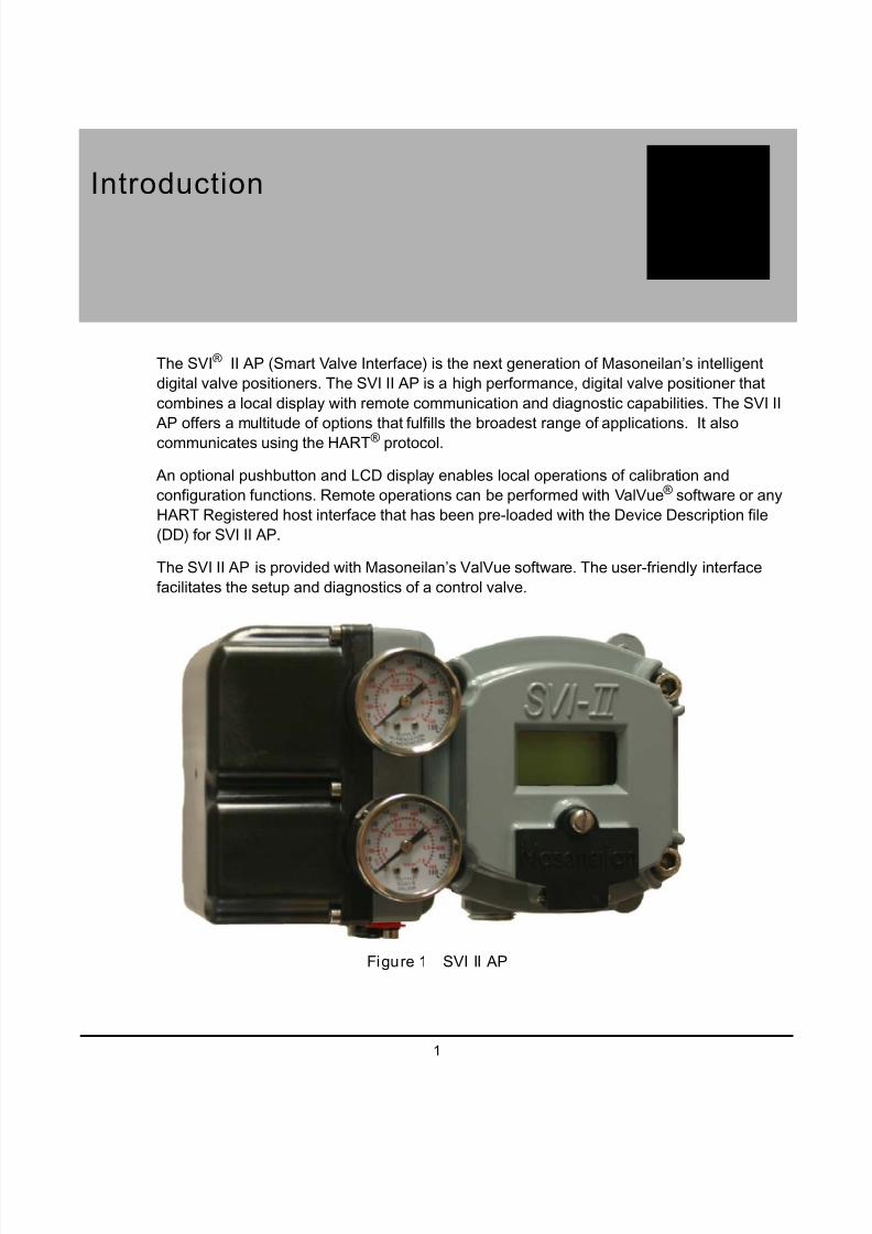
1 SVI II AP ................................................................................................................................ 1
2 SVI II AP Components........................................................................................................... 8
3 SVI II AP Dimensions............................................................................................................. 9
4 Camflex with Mounting Bracket (Side View) ........................................................................ 14
5 Camflex ATO Mounting (Front View)................................................................................... 15
6 Mounting Bracket on Air-to-Close Actuator.......................................................................... 15
7 Model 33 Actuator................................................................................................................ 16
8 Magnet Holder for Reciprocating Valves ............................................................................. 18
9 Reciprocating Valve Mounting Bracket ................................................................................ 19
10 Lever for Model 87/88 Multispring Actuator ......................................................................... 19
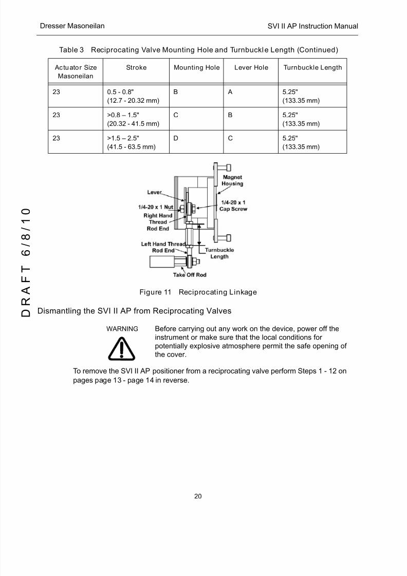
11 Reciprocating Linkage ......................................................................................................... 20
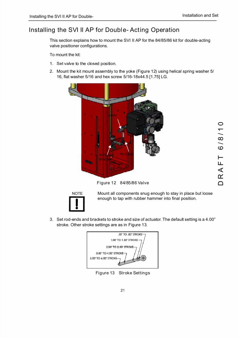
12 84/85/86 Valve..................................................................................................................... 21
13 Stroke Settings..................................................................................................................... 21
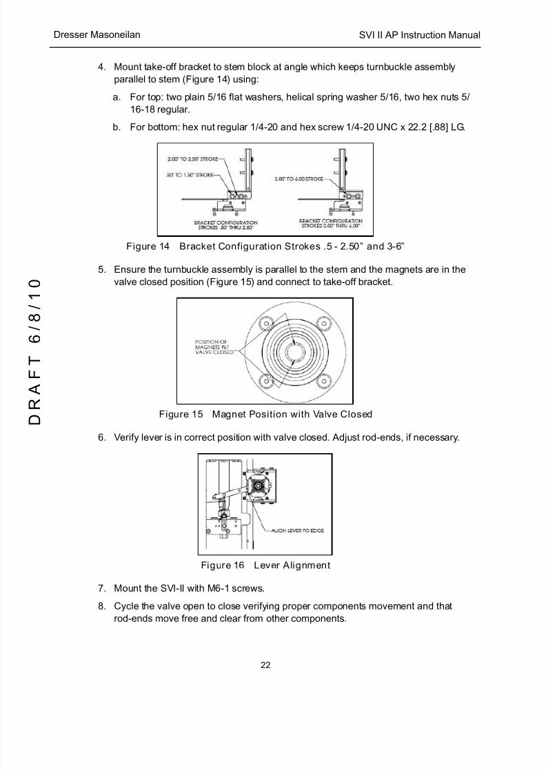
14 Bracket Configuration Strokes .5 - 2.50” and 3-6” ............................................................... 22
15 Magnet Position with Valve Closed...................................................................................... 22
16 Lever Alignment ................................................................................................................... 22
17 Remote Position Sensor Mounting ...................................................................................... 25
18 Remote Position Sensor (Cover Removed) and Wiring....................................................... 26
19 Installing SMARTS Assistant from CD................................................................................. 27
20 SMARTS Assistant - Commissioning the Remote Position Sensor..................................... 28
21 Air Ports on Single Acting Positioner ................................................................................... 30
22 Air Ports on Double Acting Positioner.................................................................................. 31
23 Magnet Orientation for Rotary Valves with Valve Closed .................................................... 37
24 Magnet Orientation for 90° Valve Rotation with De-energized Actuator .............................. 38
25 Magnet Holder for Reciprocating Valves ............................................................................. 38
26 Reciprocating Valve Mounting Bracket ................................................................................ 39
27 Connections to Electronics Module (via Terminal Board) .................................................... 41
28 SVI II AP Display.................................................................................................................. 47
29 NORMAL Operation and MANUAL Menu Structures .......................................................... 49
30 CONFIGure Menu................................................................................................................ 50
31 CALIBration Menu................................................................................................................ 54
32 VIEW DATA Menu ............................................................................................................... 56
33 FAILSAFE Menu.................................................................................................................. 58
34 ValVue Options .................................................................................................................... 6435 Configuration Pushbutton Guide.......................................................................................... 70
36 Calibration Pushbutton Guide.............................................................................................. 74
37 SVI II AP HART Communicator Connections ...................................................................... 75
38 General Purpose and Explosion Proof Installation .............................................................. 82
39 Intrinsically Safe Installation................................................................................................. 83
40 ValVue Activate Set Options on Device Screen .................................................................. 89
41 ValVue Setup Options for Multi-Drop................................................................................... 90

5/8/2018 EW2002 AP 0610 Web_SVI2Ap With Remote Sensor - slidepdf.com
http://slidepdf.com/reader/full/ew2002-ap-0610-websvi2ap-with-remote-sensor 10/160
SVI II AP Instruction Manual
viii
D R
A F T
6 / 8 / 1 0
Dresser Masoneilan
42 Split Range with Isolator ...................................................................................................... 92
43 Split Range with Supplemental Power Supply - Non-Hazardous ........................................ 94
44 Intrinsically Safe Installation with Zener Barrier and HART Filter ........................................ 98
45 Intrinsically Safe Installation with Galvanic Isolator ........................................................... 100
46 Block Diagram with I/P Converter and Pressure Sensor ................................................... 103
47 Pneumatic Module with Single Acting Relay ..................................................................... 107
48 Double Acting Pneumatic Relay ........................................................................................ 108
49 SVI II AP Display and Pneumatic Covers .......................................................................... 110
50 SVI II AP Model Numbering............................................................................................... 122
51 ATO and ATC Action with Linear Positioner Characteristics ............................................. 128
52 ATO and ATC Action in Percentage of Positioner Characteristics .................................... 129

5/8/2018 EW2002 AP 0610 Web_SVI2Ap With Remote Sensor - slidepdf.com
http://slidepdf.com/reader/full/ew2002-ap-0610-websvi2ap-with-remote-sensor 11/160
ix
Tables
1 SVI II AP Installation Steps ..................................................................................................10
2 Magnet Orientation on Rotary Actuators.............................................................................. 16
3 Reciprocating Valve Mounting Hole and Turnbuckle Length ............................................... 194 Remote Position Sensor Specifications............................................................................... 23
5 Remote Position Sensor Turnbuckle Length ....................................................................... 25
6 Air Supply Requirements ..................................................................................................... 29
7 Double Acting Positioner ATO ⁄ ATC Settings forReciprocating Valves ........................................................................................................... 32
8 SVI II AP Models and Functionality...................................................................................... 40
9 Pushbutton Lock Security Level........................................................................................... 43
10 Guidelines for Characteristic Choice.................................................................................... 52
11 Error Messages.................................................................................................................... 59
12 Pushbutton Lock Security Level........................................................................................... 67
13 VIEW DATA Settings ........................................................................................................... 6914 Compliance Voltage for Single Channel Zener with 22 AWG Cable ................................... 84
15 Compliance Voltage for Galvanic Isolator with 22 AWG Cable ........................................... 85
16 Compliance Voltage for No Barrier with HART Filter and Resistor and 18 AWG Cable...... 85
17 Supplemental Voltage for Split Range................................................................................. 93
18 Environmental Specifications............................................................................................. 117
19 Operational Specifications*................................................................................................ 118
20 Input Signal, Power, and Display Specifications................................................................ 119
21 Construction Material Specifications.................................................................................. 119
22 System Connectivity .......................................................................................................... 120
23 Pneumatics Single Acting Standard Flow.......................................................................... 120
24 Pneumatics Double Acting Standard Flow......................................................................... 12125 Tight Shutoff Parameters for HIgh Pressure Liquid Letdown Trim .................................... 136

5/8/2018 EW2002 AP 0610 Web_SVI2Ap With Remote Sensor - slidepdf.com
http://slidepdf.com/reader/full/ew2002-ap-0610-websvi2ap-with-remote-sensor 12/160
SVI II AP Instruction Manual
This page intentionally left blank.
D R
A F T
6 / 8 / 1 0
5/8/2018 EW2002 AP 0610 Web_SVI2Ap With Remote Sensor - slidepdf.com
http://slidepdf.com/reader/full/ew2002-ap-0610-websvi2ap-with-remote-sensor 13/160
1
1Introduction
The SVI ® II AP (Smart Valve Interface) is the next generation of Masoneilan’s intelligent
digital valve positioners. The SVI II AP is a high performance, digital valve positioner that
combines a local display with remote communication and diagnostic capabilities. The SVI II
AP offers a multitude of options that fulfills the broadest range of applications. It alsocommunicates using the HART ® protocol.
An optional pushbutton and LCD display enables local operations of calibration and
configuration functions. Remote operations can be performed with ValVue ® software or any
HART Registered host interface that has been pre-loaded with the Device Description file
(DD) for SVI II AP.
The SVI II AP is provided with Masoneilan’s ValVue software. The user-friendly interface
facilitates the setup and diagnostics of a control valve.
Figure 1 SVI II AP

5/8/2018 EW2002 AP 0610 Web_SVI2Ap With Remote Sensor - slidepdf.com
http://slidepdf.com/reader/full/ew2002-ap-0610-websvi2ap-with-remote-sensor 14/160
SVI II AP Instruction Manual
2
D R
A F T
6 / 8 / 1 0
Dresser Masoneilan
ValVue Software
Not only does ValVue provide the ability to quickly and easily set up the SVI II AP you can
also monitor operation and diagnose problems with ValVue’s advanced diagnostic
capabilities.
ValVue Lite
ValVue Lite software is shipped with each SVI II AP for positioner calibration and
configuration. ValVue Lite software is freeware and does not require any registration. It
provides functions to properly set up and start up an SVI II AP positioner on any type of
control valve.
System Requirements
ValVue Lite runs on IBM compatible computers. Minimum requirements for all versions of
ValVue software are Windows 2000, XP, 64 MB RAM, serial or USB port connected to a
HART ® modem, and a CD-ROM drive.
ValVue Trial Version
The SVI II AP is provided with a trial version of ValVue. For 60 days after the initial
installation, ValVue provides the capability of configuring, calibrating, diagnosing, cloning,
trending and much more. After the 60 trial period ValVue must be registered for use.
ValVue is a user-friendly, graphical interface that allows an efficient setup of an SVI II AP
mounted on any control valve assembly. Because of its
What-You-See-Is-What-You-Get (WYSIWYG) software environment, it is a very simple
user-interface.
ValVue functionality includes:
q Setup Wizard
q Remote display of valve position, actuator pressure(s)
q Set calibration parameters
q Set configuration parameters
q Monitor status ⁄ error indicators
q Input/Output configuration
q Remote calibration of the SVI II AP
q Remote configuration of the SVI II AP
q Remote operation of the SVI II AP
q Backup and restore configuration (clone device)
q Trend setpoint, valve position, actuator pressure
5/8/2018 EW2002 AP 0610 Web_SVI2Ap With Remote Sensor - slidepdf.com
http://slidepdf.com/reader/full/ew2002-ap-0610-websvi2ap-with-remote-sensor 15/160
3
Operational Overview Introduction
q Display comparative test results (full version only)
q Perform diagnostic test procedures (full version only)
Advanced and Online Diagnostics
The SVI II AP offers various levels of control valve diagnostics. Up to five pressure
sensors that detect circuit board temperature, loop current, and reference voltage, are
available for diagnostics.
For more details on the use of ValVue software, refer to the ValVue User’s Guide. Contact
Masoneilan or your local Masoneilan representative to obtain licensing information.
Contact Masoneilan
For the most recent software visit our SVI II AP web site at: www.masoneilan.com
Operational Overview
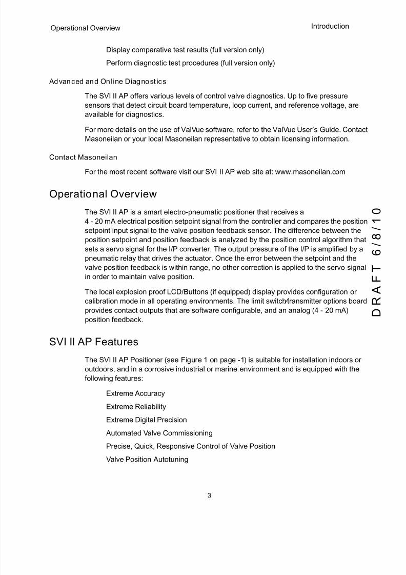
The SVI II AP is a smart electro-pneumatic positioner that receives a
4 - 20 mA electrical position setpoint signal from the controller and compares the position
setpoint input signal to the valve position feedback sensor. The difference between the
position setpoint and position feedback is analyzed by the position control algorithm that
sets a servo signal for the I/P converter. The output pressure of the I/P is amplified by a
pneumatic relay that drives the actuator. Once the error between the setpoint and the
valve position feedback is within range, no other correction is applied to the servo signal
in order to maintain valve position.
The local explosion proof LCD/Buttons (if equipped) display provides configuration or
calibration mode in all operating environments. The limit switch ⁄ transmitter options boardprovides contact outputs that are software configurable, and an analog (4 - 20 mA)
position feedback.
SVI II AP Features
The SVI II AP Positioner (see Figure 1 on page -1) is suitable for installation indoors or
outdoors, and in a corrosive industrial or marine environment and is equipped with the
following features:
q Extreme Accuracy
q Extreme Reliability
q Extreme Digital Precision
q Automated Valve Commissioning
q Precise, Quick, Responsive Control of Valve Position
q Valve Position Autotuning
5/8/2018 EW2002 AP 0610 Web_SVI2Ap With Remote Sensor - slidepdf.com
http://slidepdf.com/reader/full/ew2002-ap-0610-websvi2ap-with-remote-sensor 16/160
SVI II AP Instruction Manual
4
D R
A F T
6 / 8 / 1 0
Dresser Masoneilan
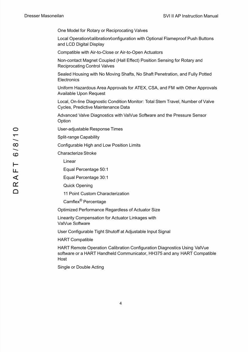
q One Model for Rotary or Reciprocating Valves
q Local Operation ⁄ calibration ⁄ configuration with Optional Flameproof Push Buttons
and LCD Digital Display
q Compatible with Air-to-Close or Air-to-Open Actuators
q Non-contact Magnet Coupled (Hall Effect) Position Sensing for Rotary andReciprocating Control Valves
q Sealed Housing with No Moving Shafts, No Shaft Penetration, and Fully Potted
Electronics
q Uniform Hazardous Area Approvals for ATEX, CSA, and FM with Other Approvals
Available Upon Request
q Local, On-line Diagnostic Condition Monitor: Total Stem Travel, Number of Valve
Cycles, Predictive Maintenance Data
q Advanced Valve Diagnostics with ValVue Software and the Pressure Sensor
Optionq User-adjustable Response Times
q Split-range Capability
q Configurable High and Low Position Limits
q Characterize Stroke
q Linear
q Equal Percentage 50:1
q Equal Percentage 30:1
q Quick Openingq 11 Point Custom Characterization
q Camflex ® Percentage
q Optimized Performance Regardless of Actuator Size
q Linearity Compensation for Actuator Linkages with
ValVue Software
q User Configurable Tight Shutoff at Adjustable Input Signal
q HART Compatible
q HART Remote Operation Calibration Configuration Diagnostics Using ValVue
software or a HART Handheld Communicator, HH375 and any HART Compatible
Host
q Single or Double Acting
5/8/2018 EW2002 AP 0610 Web_SVI2Ap With Remote Sensor - slidepdf.com
http://slidepdf.com/reader/full/ew2002-ap-0610-websvi2ap-with-remote-sensor 17/160
5
Available Options Introduction
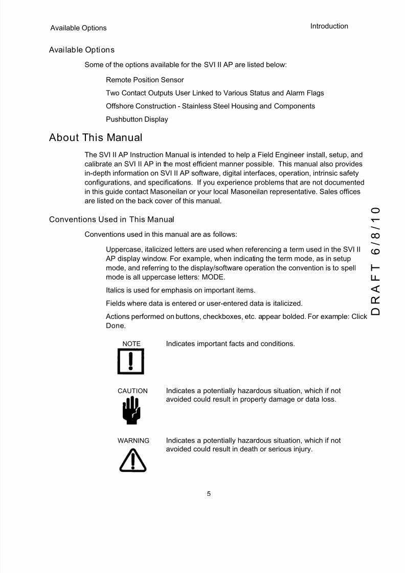
Available Options
Some of the options available for the SVI II AP are listed below:
q Remote Position Sensor
q Two Contact Outputs User Linked to Various Status and Alarm Flags
q Offshore Construction - Stainless Steel Housing and Components
q Pushbutton Display
About This Manual
The SVI II AP Instruction Manual is intended to help a Field Engineer install, setup, and
calibrate an SVI II AP in the most efficient manner possible. This manual also provides
in-depth information on SVI II AP software, digital interfaces, operation, intrinsic safety
configurations, and specifications. If you experience problems that are not documented
in this guide contact Masoneilan or your local Masoneilan representative. Sales offices
are listed on the back cover of this manual.
Conventions Used in This Manual
Conventions used in this manual are as follows:
q Uppercase, italicized letters are used when referencing a term used in the SVI II
AP display window. For example, when indicating the term mode , as in setup
mode, and referring to the display/software operation the convention is to spell
mode is all uppercase letters: MODE .
q Italics is used for emphasis on important items.
q Fields where data is entered or user-entered data is italicized .
q Actions performed on buttons, checkboxes, etc. appear bolded. For example: Click
Done.
NOTE Indicates important facts and conditions.
CAUTION Indicates a potentially hazardous situation, which if not
avoided could result in property damage or data loss.
WARNING Indicates a potentially hazardous situation, which if not avoided could result in death or serious injury.

5/8/2018 EW2002 AP 0610 Web_SVI2Ap With Remote Sensor - slidepdf.com
http://slidepdf.com/reader/full/ew2002-ap-0610-websvi2ap-with-remote-sensor 18/160
SVI II AP Instruction Manual
This page intentionally left blank.
D R
A F T
6 / 8 / 1 0

5/8/2018 EW2002 AP 0610 Web_SVI2Ap With Remote Sensor - slidepdf.com
http://slidepdf.com/reader/full/ew2002-ap-0610-websvi2ap-with-remote-sensor 19/160
7
2Installation and Set Up
Overview
The SVI II AP (Smart Valve Interface - see Figure 2 on page 8) is the next generation of
Masoneilan’s intelligent digital valve positioners. The SVI II AP is a high performance, digitalvalve positioner that combines a local display with remote communication and diagnostic
capabilities. The SVI II AP is available with a variety of options to fulfill diverse applications
and it communicates using the HART ® protocol.
Prior to beginning the installation process review the safety information on page iii at the beginning of this manual.NOTE

5/8/2018 EW2002 AP 0610 Web_SVI2Ap With Remote Sensor - slidepdf.com
http://slidepdf.com/reader/full/ew2002-ap-0610-websvi2ap-with-remote-sensor 20/160
SVI II AP Instruction Manual
8
D R
A F T
6 / 8 / 1 0
Dresser Masoneilan
Figure 2 SVI II AP Components
SVI II AP Cover SVI II AP Assembled
ElectronicsModule
Pneumatic Train andCover (I/P Module,Relay)
Relay
I/PManifold

5/8/2018 EW2002 AP 0610 Web_SVI2Ap With Remote Sensor - slidepdf.com
http://slidepdf.com/reader/full/ew2002-ap-0610-websvi2ap-with-remote-sensor 21/160
9
SVI II AP Dimensions and Weights Installation and Se
SVI II AP Dimensions and Weights
Figure 3 illustrates the dimensions and weight of the SVI II AP.
Figure 3 SVI II AP Dimensions
1 2 2 . 5 5 m m
3 4 . 0 0 m m
1 . 9 0 m m
3 8 . 1 0 m m
4
7 . 5 8 m m
7 4 . 9 7 m m
9 6 . 5 6 m m
3 4 . 0 0 m m
2 3 . 0 0 m m
( 7 4
. 9 7 m m )
2 0 3 . 9 3 m m
8 . 0 3 i n
4 . 8 2 5 i n
4 . 9 3 i n
1 2 5 . 3 3 m m
1 . 3 4 i n
0 . 0 7 5 i n
( 1
. 9 0 m m )
( 0 . 0 7 5 i n )
4 . 1 9 i n
1 0 6 . 3 6 m m
2 . 1 i n
5 3 . 1 8 m m
1 . 5 i n
1 . 8 7 i n
2 . 9 5 i n
3 . 8 i n
1 4 5 . 3 7 m m
5 . 7 2 i n
1 . 3 4 i n
. 9 0 i n
(
2 . 9 5 i n )
W e i g h t S t a n d a r d - 7 . 4 l b s ( 3 . 3 5 7 k g )
C e n t e r o f G r a v i t y
W e i g h t S t a i n l e s s S t e e l - 1 6 l b s / 7 . 2 5 7 k g
5/8/2018 EW2002 AP 0610 Web_SVI2Ap With Remote Sensor - slidepdf.com
http://slidepdf.com/reader/full/ew2002-ap-0610-websvi2ap-with-remote-sensor 22/160
SVI II AP Instruction Manual
10
D R
A F T
6 / 8 / 1 0
Dresser Masoneilan
Pre-Installation Issues
Storage
If the SVI II AP is stored for a long duration, you must keep the housing sealed against
weather, fluids, particles, and insects. To prevent damage to the SVI II AP:
q Use the plugs provided with shipment to plug the ¼ NPT air connections, on the
positioner and on the air filter regulator set.
q Do not allow standing water to accumulate.
q Observe storage temperature requirements.
Unpacking
Exercise care when unpacking the control valve and its mounted accessories. The SVI II
AP container includes a CD-ROM with ValVue Lite, ValVue Trial Version, and manuals.
Installation Steps
If you experience problems that are not documented in this guide call Masoneilan or your
local Masoneilan representative. Sales offices are listed on the last page of this
document.
The steps necessary to complete the SVI II AP installation and software setup are
outlined in Table 1.
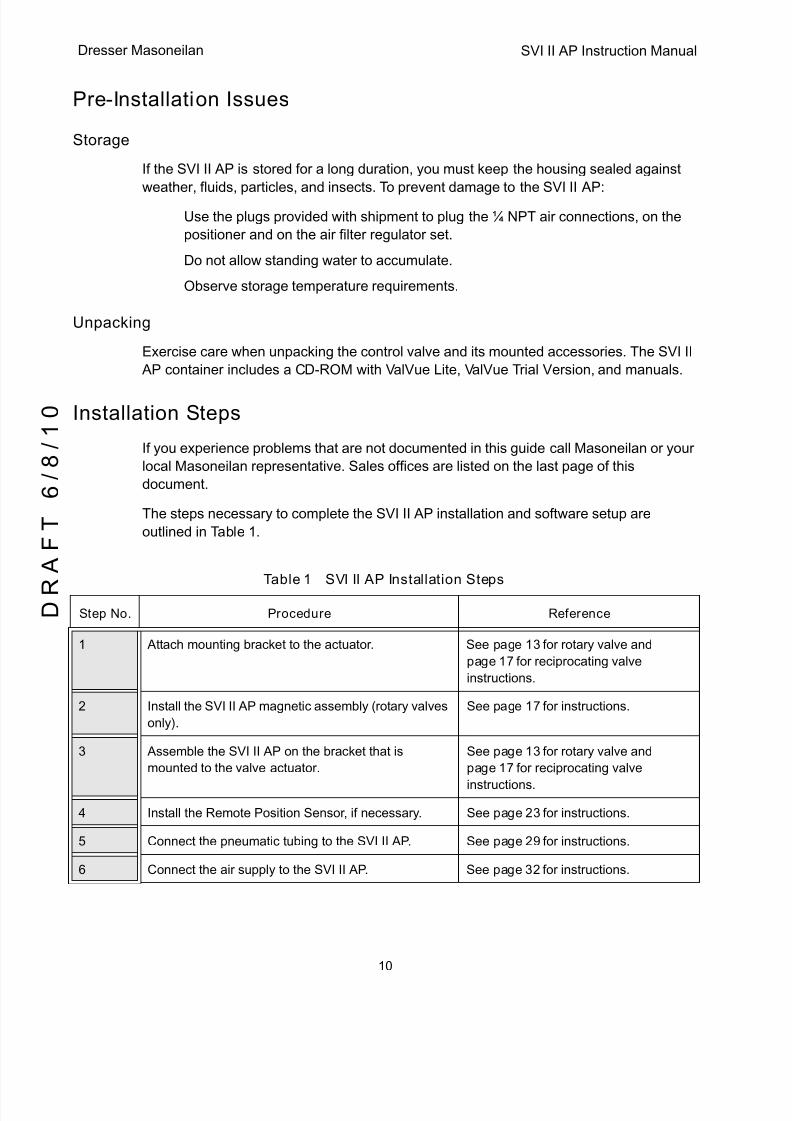
Table 1 SVI II AP Installation Steps
Step No. Procedure Reference
1 Attach mounting bracket to the actuator. See page 13 for rotary valve and
page 17 for reciprocating valve
instructions.
2 Install the SVI II AP magnetic assembly (rotary valves
only).
See page 17 for instructions.
3 Assemble the SVI II AP on the bracket that is
mounted to the valve actuator.
See page 13 for rotary valve and
page 17 for reciprocating valve
instructions.
4 Install the Remote Position Sensor, if necessary. See page 23 for instructions.
5 Connect the pneumatic tubing to the SVI II AP. See page 29 for instructions.
6 Connect the air supply to the SVI II AP. See page 32 for instructions.
5/8/2018 EW2002 AP 0610 Web_SVI2Ap With Remote Sensor - slidepdf.com
http://slidepdf.com/reader/full/ew2002-ap-0610-websvi2ap-with-remote-sensor 23/160
11
Installation Notes Installation and Se
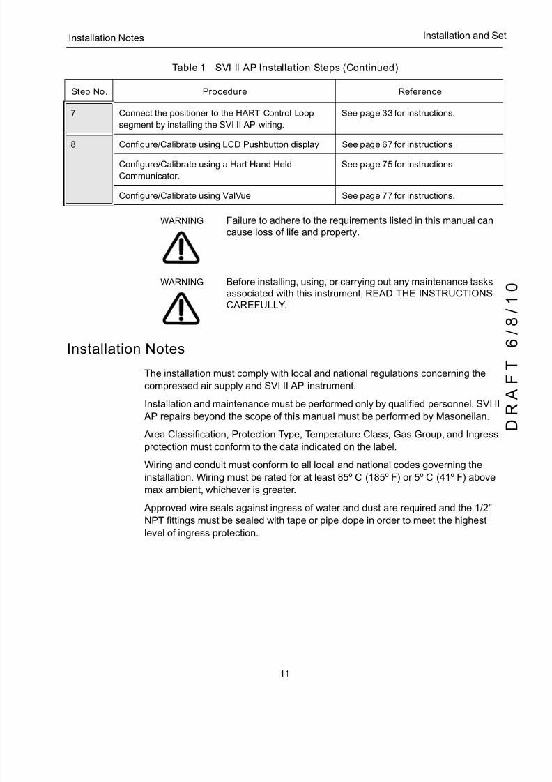
WARNING Failure to adhere to the requirements listed in this manual can cause loss of life and property.
WARNING Before installing, using, or carrying out any maintenance tasks associated with this instrument, READ THE INSTRUCTIONS CAREFULLY .
Installation Notes
q The installation must comply with local and national regulations concerning the
compressed air supply and SVI II AP instrument.
q Installation and maintenance must be performed only by qualified personnel. SVI II
AP repairs beyond the scope of this manual must be performed by Masoneilan.
q Area Classification, Protection Type, Temperature Class, Gas Group, and Ingress
protection must conform to the data indicated on the label.
q Wiring and conduit must conform to all local and national codes governing the
installation. Wiring must be rated for at least 85º C (185º F) or 5º C (41º F) above
max ambient, whichever is greater.
q Approved wire seals against ingress of water and dust are required and the 1/2"
NPT fittings must be sealed with tape or pipe dope in order to meet the highest
level of ingress protection.
7 Connect the positioner to the HART Control Loop
segment by installing the SVI II AP wiring.
See page 33 for instructions.
8 Configure/Calibrate using LCD Pushbutton display See page 67 for instructions
Configure/Calibrate using a Hart Hand Held
Communicator.
See page 75 for instructions
Configure/Calibrate using ValVue See page 77 for instructions.
Table 1 SVI II AP Installation Steps (Continued)
Step No. Procedure Reference
5/8/2018 EW2002 AP 0610 Web_SVI2Ap With Remote Sensor - slidepdf.com
http://slidepdf.com/reader/full/ew2002-ap-0610-websvi2ap-with-remote-sensor 24/160
SVI II AP Instruction Manual
12
D R
A F T
6 / 8 / 1 0
Dresser Masoneilan
Before Powering Up
Before powering up the SVI II AP:
1. Verify that the pneumatic connections and electronic cover screws are tightened. This
is important to maintain the ingress protection level and the integrity of the flameproof
enclosure.2. If the installation is Intrinsically Safe, then check that the proper barriers are installed
and the field wiring meets local and national codes for an IS installation.
3. If the installation is Non-Incendive, then check that all the electrical connections are to
approved devices and wiring meets local and national codes.
4. Verify that the markings on the label are consistent with the application.
NOTE For Hazardous Location Installation information refer to Section “Specifications and References” .
Mounting the Positioner
This guide provides installation instructions for mounting an SVI II AP on both rotary and
reciprocating actuated valves. The mounting process can be broken down into the
following:
q Attach the mounting bracket to the actuator.
q Install the magnetic assembly (rotary only).
q Assemble the SVI II AP on the mounting bracket.
NOTE Mount the SVI II AP with the conduit connections down in order to facilitate drainage of condensate from the conduit.
Necessary Precautions
To avoid injury or the process being affected when installing or replacing a positioner on a
control valve, ensure that:
q If the valve is located in a hazardous area make sure the area has been certified
as safe or that all electrical power to the area has been disconnected beforeremoving any covers or disconnecting any leads.
q Shut off air supply to the actuator and to any valve mounted equipment.
q Ensure the valve is isolated from the process by either shutting off the process or
using bypass valves for isolation. Tag shutoff or bypass valves to guard against a
turn-on while work is in progress.
q Purge air from actuator and check that valve is in its unenergized position.
5/8/2018 EW2002 AP 0610 Web_SVI2Ap With Remote Sensor - slidepdf.com
http://slidepdf.com/reader/full/ew2002-ap-0610-websvi2ap-with-remote-sensor 25/160
13
Filter Regulator and Tubing Installation and Se
Filter Regulator and Tubing
The use of a Masoneilan filter regulator with a 5-micron filter is recommended for the air
supply. Use 1 ⁄ 4" (6.35 mm) minimum tubing between filter regulator, SVI II AP and the
actuator, with 3 ⁄ 8" (9.53 mm) used for larger actuators. Use a soft setting anaerobic
hydraulic seal such as Loctite Hydraulic Seal 542 for sealing the pneumatic pipe threads.
Follow manufacturers instructions.
NOTE Maximum allowable air supply pressure to the SVI II AP varies according to actuator and valve size and type. See pressure drop tables in valve specification sheets to determine correct positioner supply pressure. Minimum supply pressure should be 5 to 10 psi (.345 bar - .69 bar) (34.485 - 68.97 kPa) above maximum spring pressure.
Mounting the SVI II AP on Rotary Valves
This procedure is used to mount the SVI II AP on rotary control valves that have less than
60° rotation, such as a Camflex ® or a Varimax ® . For valves that have rotation greater than
60° refer to “Rotary - 90°” on page 16
Required Tools
The following tools are needed to complete the rotary valve installation:
q 3 ⁄ 16" Hex Key with tee handle
q 5 ⁄ 32" Hex Key
q 3 mm, 4mm, 5mm Hex Key
q 7 ⁄ 16" Wrench
To mount the SVI II AP:
1. Attach the SVI II AP rotary mounting bracket to the valve actuator using two (2) 5 ⁄ 16 -
18 UNC flat-head cap screws. Mount the SVI II AP as shown in Figure 5 on page 15,
ATO or in Figure 6 on page 15, ATC. In the preferred mounting position, the long end
of the mounting bracket is on your left when facing the actuator, for any position of the
valve and actuator.
2. Bolt the extension shaft to the valve position take-off shaft using a 1 ⁄ 4 - 28 UNF socketflathead screw. Secure the machine screw holding the extension shaft with a torque of
144 in-lbs (16.269 N-m).
3. Upon internal valve pressure the thrust shaft is pushed out to the mechanical stops,
usually a thrust bearing. On valves where the valve position take-off is mounted
directly on the end of the plug shaft, a Camflex for example, the shaft must be bearing
on its stop to properly set up the SVI II AP positioner. During hydrostatic testing the
shaft is thrust to its stop and a normally tightened packing retains it in that position.

5/8/2018 EW2002 AP 0610 Web_SVI2Ap With Remote Sensor - slidepdf.com
http://slidepdf.com/reader/full/ew2002-ap-0610-websvi2ap-with-remote-sensor 26/160
SVI II AP Instruction Manual
14
D R
A F T
6 / 8 / 1 0
Dresser Masoneilan
4. On vacuum service, the valve shaft can be drawn into the body by the vacuum acting
on the shaft, but the magnetic coupling must be assembled flush with the mounting
bracket with the shaft pulled fully out to its thrust bearing. Check that the endplay from
the vacuum position to the fully extended position is less than 0.06 in. (1.524 mm)
5. Slide the magnet holder into the extension shaft. The location of the magnets is in the
ring of the magnet holder. The magnetic axis is the imaginary line through the centerof both magnets.
6. Rotate the magnet holder so that the magnet axis is vertical when the valve is in the
closed position. See Figure 5 and Figure 6.
7. Align the end of the magnet holder flush with the end of the mounting bracket. Secure
the magnet holder with two M6 set screws.
8. Slide the V-Seal over the magnet holder.
9. Secure the SVI II AP onto the mounting bracket using four M6 x 20 mm Socket Head
Cap Screws.
10. Ensure no interference exists with the position sensor protrusion.
11. Ensure that the V-Seal makes contact with the skirt around the position sensor
protrusion on SVI II AP housing.
Figure 4 Camflex with Mounting Bracket (Side View)

5/8/2018 EW2002 AP 0610 Web_SVI2Ap With Remote Sensor - slidepdf.com
http://slidepdf.com/reader/full/ew2002-ap-0610-websvi2ap-with-remote-sensor 27/160
15
Required Tools Installation and Se
Figure 5 Camflex ATO Mounting (Front View)
Figure 6 Mounting Bracket on Air-to-Close Actuator

5/8/2018 EW2002 AP 0610 Web_SVI2Ap With Remote Sensor - slidepdf.com
http://slidepdf.com/reader/full/ew2002-ap-0610-websvi2ap-with-remote-sensor 28/160
SVI II AP Instruction Manual
16
D R
A F T
6 / 8 / 1 0
Dresser Masoneilan
Figure 7 Model 33 Actuator
Rotary - 90°
For actuators with 60 to 120° rotation, follow the instructions in “Mounting the SVI II AP
on Rotary Valves” on page 13 except mount the magnet at plus or minus 45° while the
actuator de-energized as shown in Figure 7 on page 16.
Table 2 Magnet Orientation on Rotary Actuators
Rotary Actuator Type Magnet Setting - ATO Magnet Setting - ATC
Camflex Actuator is energized __ Magnet Axis is Vertical
Figure 6
Camflex Actuator is de-energized Magnet Axis is Vertical
Figure 5
__
Varimax ®
Actuator is energized
__ Magnet Axis is Vertical
Varimax
Actuator is de-energized
Magnet Axis is Vertical __
Model 33 in clockwise to open valve
Actuator is de-energized
(36000 Series Control Ball, 37000 MiniTork ® )
Magnet axis 45° to right of
vertical position in Figure 7
Magnet axis 45° to right
of vertical
Double acting cylinders at mid-travel Magnet Axis Vertical Magnet Axis Vertical
5/8/2018 EW2002 AP 0610 Web_SVI2Ap With Remote Sensor - slidepdf.com
http://slidepdf.com/reader/full/ew2002-ap-0610-websvi2ap-with-remote-sensor 29/160
17
Magnet Orientation on Rotary Installation and Se
Magnet Orientation on Rotary Valve Shafts
The same mounting hardware is used for Models 35, 30 actuators. For each actuator type
the magnetic coupling must be properly oriented to the active sensing angle of the
positioners Hall Effect sensor. The active range of the Hall-Effect sensor is plus ⁄ minus 70°
from the null magnet axis. If the total valve travel is less than 60°, allowing a margin for
tolerances, the best accuracy is achieved by mounting the magnet with the axis vertical inthe valve-closed position. Note the location of the magnets in the ring of the magnet
holder. The axis of the magnets is the line through the centers of both magnets. Mount
the magnet holder with the magnet axis vertical on the 35, 30 when the valve is closed. If
travel of the valve exceeds 60°, the magnet must be assembled to the rotary valve shaft
so that the magnet axis is vertical when the valve is at mid-scale.
Dismantling the SVI II AP from Rotary Valves
WARNING Before carrying out any work on the device, power off the instrument or make sure that the device’s location conditions
for potentially explosive atmosphere permit the safe opening of the cover.
To remove the SVI II AP positioner from a rotary valve perform Steps 1 - 8 on page
page 10 in reverse.
Mounting the SVI II AP on Reciprocating Valves
This section describes the procedure for mounting the SVI II AP on Reciprocating Valves
(using Masoneilan’s 87 ⁄ 88 Multi-Spring actuators as an example).
Tools required:
q 7 ⁄ 16" Combination Wrench (2 required)
q 3 ⁄ 8" Combination Wrench
q 1 ⁄ 2" Combination Wrench
q Phillips Head Screw Driver
q 5 mm Hex Key Wrench
Mounting the SVI II AP on a Reciprocating Actuator
1. Ensure that the lever is pinned to the magnet assembly and held securely by an M5flat head screw to ensure that the magnet axis is vertical when the lever is in the valve
closed position. Tighten the lever screw securely.
2. Mount the SVI II AP reciprocating mounting bracket to the actuator using two (2) 5 ⁄ 16
- 18 UNC cap screws. The mounting location of the bracket depends on the size and
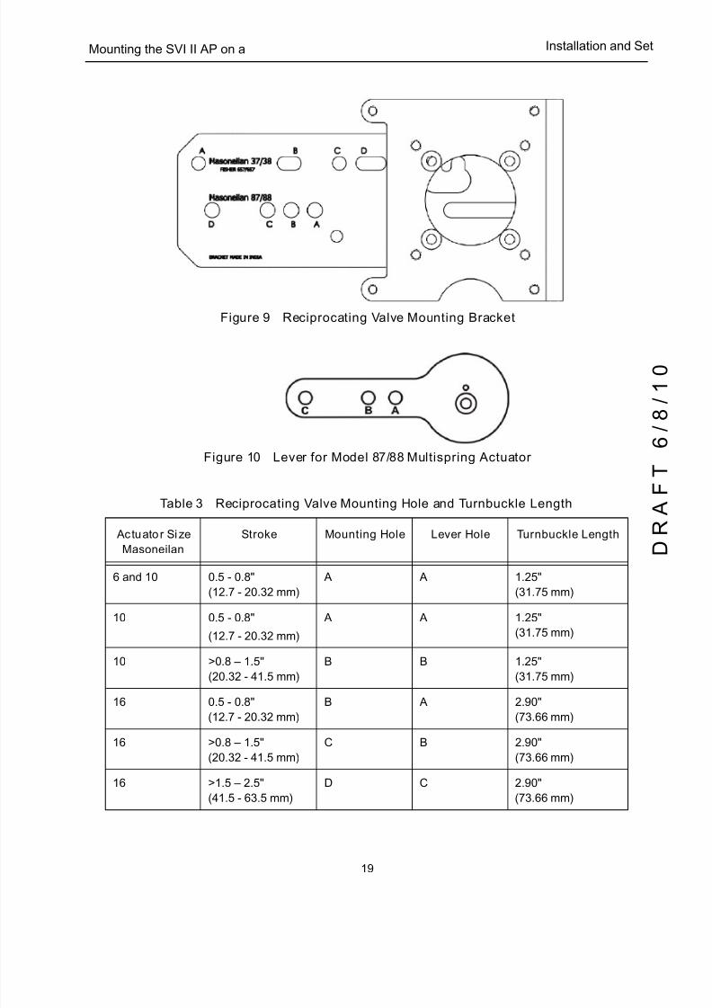
stroke of the actuator. Refer to Figure 9 on page 19 and Figure 3 on page 19.

5/8/2018 EW2002 AP 0610 Web_SVI2Ap With Remote Sensor - slidepdf.com
http://slidepdf.com/reader/full/ew2002-ap-0610-websvi2ap-with-remote-sensor 30/160
SVI II AP Instruction Manual
18
D R
A F T
6 / 8 / 1 0
Dresser Masoneilan
3. Select mounting hole A, B, C or D for the stroke of the valve. For example, hole B is
shown in Figure 10 on page 19 for a size 10 actuator with 1.0" stroke. Unless
otherwise specified, the SVI II AP mounting assumes that the actuator is in the normal
upright position. The mounting hole in the slotted opening of the mounting bracket
must be left when facing the actuator, with the actuator in the upright position.
4. Thread the take-off rod to the actuator stem connector. Refer to Figure 11 on page 20.Ensure that the travel pointer located on the coupling is correctly positioned.
5. Attach the right hand threaded rod end to the SVI II AP lever using a 1 ⁄ 4 - 20 x 1" cap
screw and nut as shown. The lever hole position to be used depends upon the
specific valve stroke. Refer to Figure 10 on page 19 and the Reciprocating Valve
Linkage Selection, Table 3 on page 19.
6. Thread the right hand lock nut and turnbuckle onto the right hand rod end
approximately two turns. Turnbuckle length is a function of actuator size. (Refer to
Table 3 on page 19.)
7. Secure the magnet housing assembly, including the lever and right hand rod end, to
the bracket using four M5 X 10 mm flat head screws.
8. Attach the left hand threaded rod end to the take-off rod with
1 ⁄ 4 - 20 UNC nut and thread the left hand lock nut onto the rod end.
9. Move the valve to its closed position. For air to extend, this requires using air pressure
in the actuator to fully stroke the actuator. For air to retract, actuators vent the actuator
of air pressure.
10. Thread the turnbuckle onto the left hand threaded rod end. Refer to Figure 11 on
page 20.
11. Adjust the turnbuckle until the hole in the SVI II AP lever is aligned with the indicating
hole in the bracket. Tighten both turnbuckle lock nuts. (See Figure 9 on page 19.)
12. Mount the SVI II AP to the bracket and secure with four M6 socket head cap screws.
Figure 8 Magnet Holder for Reciprocating Valves
5/8/2018 EW2002 AP 0610 Web_SVI2Ap With Remote Sensor - slidepdf.com
http://slidepdf.com/reader/full/ew2002-ap-0610-websvi2ap-with-remote-sensor 31/160
19
Mounting the SVI II AP on a Installation and Se
Figure 9 Reciprocating Valve Mounting Bracket
Figure 10 Lever for Model 87/88 Multispring Actuator
Table 3 Reciprocating Valve Mounting Hole and Turnbuckle Length
Actuator Size
Masoneilan
Stroke Mounting Hole Lever Hole Turnbuckle Length
6 and 10 0.5 - 0.8"
(12.7 - 20.32 mm)
A A 1.25"
(31.75 mm)
10 0.5 - 0.8"
(12.7 - 20.32 mm)
A A 1.25"
(31.75 mm)
10 >0.8 – 1.5"
(20.32 - 41.5 mm)
B B 1.25"
(31.75 mm)
16 0.5 - 0.8"(12.7 - 20.32 mm)
B A 2.90"(73.66 mm)
16 >0.8 – 1.5"
(20.32 - 41.5 mm)
C B 2.90"
(73.66 mm)
16 >1.5 – 2.5"
(41.5 - 63.5 mm)
D C 2.90"
(73.66 mm)
5/8/2018 EW2002 AP 0610 Web_SVI2Ap With Remote Sensor - slidepdf.com
http://slidepdf.com/reader/full/ew2002-ap-0610-websvi2ap-with-remote-sensor 32/160
SVI II AP Instruction Manual
20
D R
A F T
6 / 8 / 1 0
Dresser Masoneilan
Figure 11 Reciprocating Linkage
Dismantling the SVI II AP from Reciprocating Valves
WARNING Before carrying out any work on the device, power off the instrument or make sure that the local conditions for potentially explosive atmosphere permit the safe opening of the cover.
To remove the SVI II AP positioner from a reciprocating valve perform Steps 1 - 12 on
pages page 13 - page 14 in reverse.
23 0.5 - 0.8"
(12.7 - 20.32 mm)
B A 5.25"
(133.35 mm)
23 >0.8 – 1.5"
(20.32 - 41.5 mm)
C B 5.25"
(133.35 mm)
23 >1.5 – 2.5"
(41.5 - 63.5 mm)
D C 5.25"
(133.35 mm)
Table 3 Reciprocating Valve Mounting Hole and Turnbuckle Length (Continued)
Actuator Size
Masoneilan
Stroke Mounting Hole Lever Hole Turnbuckle Length
5/8/2018 EW2002 AP 0610 Web_SVI2Ap With Remote Sensor - slidepdf.com
http://slidepdf.com/reader/full/ew2002-ap-0610-websvi2ap-with-remote-sensor 33/160
21
Installing the SVI II AP for Double- Installation and Se
Installing the SVI II AP for Double- Acting Operation
This section explains how to mount the SVI II AP for the 84/85/86 kit for double-acting
valve positioner configurations.
To mount the kit:
1. Set valve to the closed position.
2. Mount the kit mount assembly to the yoke (Figure 12) using helical spring washer 5/
16, flat washer 5/16 and hex screw 5/16-18x44.5 [1.75] LG.
Figure 12 84/85/86 Valve
NOTE Mount all components snug enough to stay in place but loose enough to tap with rubber hammer into final position.
3. Set rod-ends and brackets to stroke and size of actuator. The default setting is a 4.00”
stroke. Other stroke settings are as in Figure 13.
Figure 13 Stroke Settings
Lever
Rod-endKit Mount
Bracket
5/8/2018 EW2002 AP 0610 Web_SVI2Ap With Remote Sensor - slidepdf.com
http://slidepdf.com/reader/full/ew2002-ap-0610-websvi2ap-with-remote-sensor 34/160
SVI II AP Instruction Manual
22
D R
A F T
6 / 8 / 1 0
Dresser Masoneilan
4. Mount take-off bracket to stem block at angle which keeps turnbuckle assembly
parallel to stem (Figure 14) using:
a. For top: two plain 5/16 flat washers, helical spring washer 5/16, two hex nuts 5/
16-18 regular.
b. For bottom: hex nut regular 1/4-20 and hex screw 1/4-20 UNC x 22.2 [.88] LG.
Figure 14 Bracket Configuration Strokes .5 - 2.50” and 3-6”
5. Ensure the turnbuckle assembly is parallel to the stem and the magnets are in thevalve closed position (Figure 15) and connect to take-off bracket.
Figure 15 Magnet Position with Valve Closed
6. Verify lever is in correct position with valve closed. Adjust rod-ends, if necessary.
Figure 16 Lever Alignment
7. Mount the SVI-II with M6-1 screws.
8. Cycle the valve open to close verifying proper components movement and that
rod-ends move free and clear from other components.
5/8/2018 EW2002 AP 0610 Web_SVI2Ap With Remote Sensor - slidepdf.com
http://slidepdf.com/reader/full/ew2002-ap-0610-websvi2ap-with-remote-sensor 35/160
23
Installing the SVI II AP Remote Installation and Se
Installing the SVI II AP Remote Position Sensor
An option that is available for the SVI II AP is the Remote Position Sensor. The Remote
Position Sensor is a remotely mounted position-sensing device, that is connected
electrically to an SVI II AP valve positioner. It is used as position feedback in applications
where direct mounting of an SVI II AP to a valve actuator is not practical due, typically butnot limited to, extreme vibration, heat or radiation.
The Remote Position Sensor is a potentiometer located in an enclosure which can be
mounted on a valve or damper to indicate stem position when connected to a suitable
receiver. There is a three wire connection provided on a screw terminal block to
interconnect to the receiving device.
The SVI II AP Remote Position Sensor is suitable for installation indoors and outdoors in
an industrial environment. Mounting kits are provided to permit mounting on a variety of
valves.
WARNING Do not remove the instrument cover or connect to an
electrical circuit in a Hazardous Area unless the power is disconnected.
WARNING q Comply with current national and local regulations for
electrical installation work.
q Comply with national and local explosive atmosphere
regulations.
q Before carrying out any work on the device, power off the
instrument or make sure that the local conditions for
potentially explosive atmosphere permit the safe opening of the cover.
Table 4 Remote Position Sensor Specifications
Operating Temperature Range -55°C to 125°C (-67°F to 257°F)
Vibration Limits Vibration resistant according to ISA 75.13
Maximum Distance to SVI II AP 30 M (100 Ft.) maximum recommended, for setups with distances of
more than 30 M consult the factory
Recommended Wiring Shielded Cable up to 14 AWG
5/8/2018 EW2002 AP 0610 Web_SVI2Ap With Remote Sensor - slidepdf.com
http://slidepdf.com/reader/full/ew2002-ap-0610-websvi2ap-with-remote-sensor 36/160
SVI II AP Instruction Manual
24
D R
A F T
6 / 8 / 1 0
Dresser Masoneilan
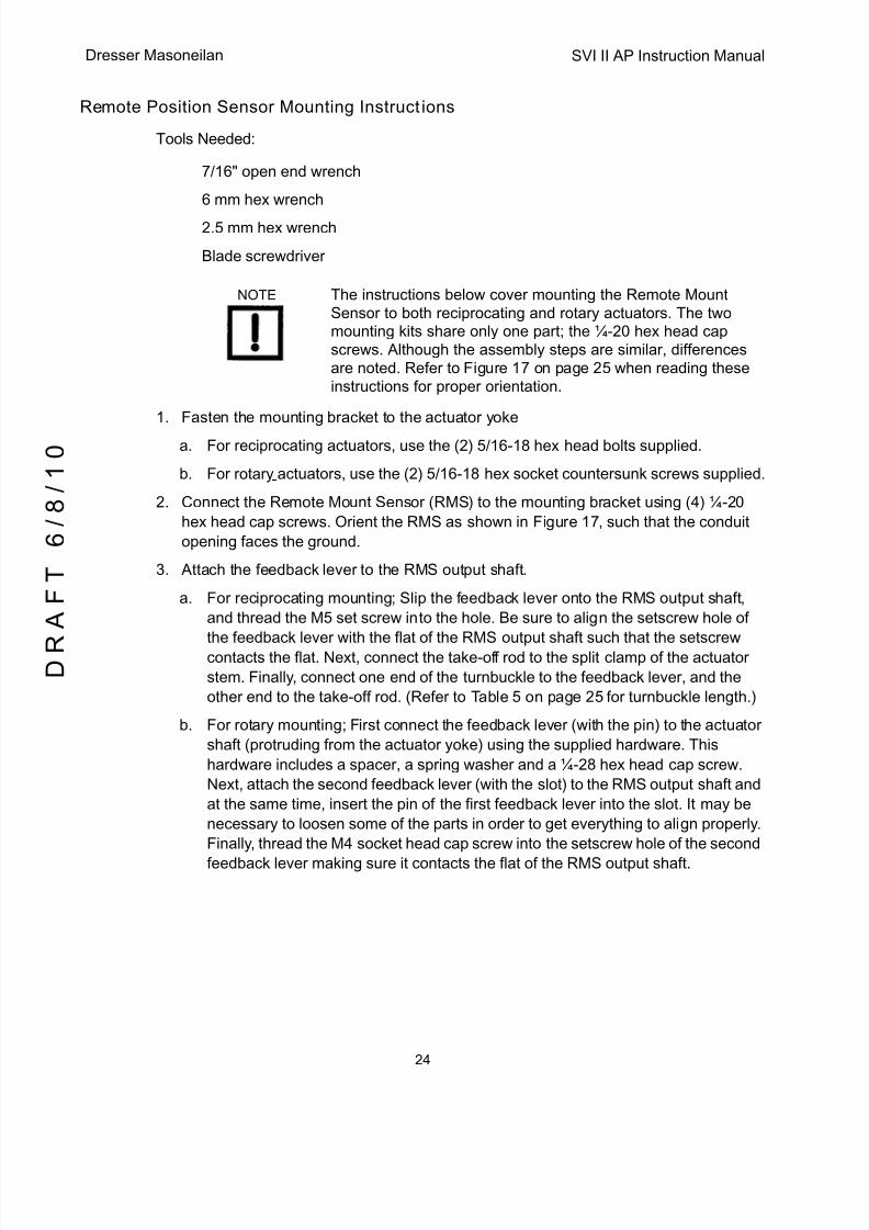
Remote Position Sensor Mounting Instructions
Tools Needed:
q 7/16" open end wrench
q 6 mm hex wrench
q 2.5 mm hex wrench
q Blade screwdriver
NOTE The instructions below cover mounting the Remote Mount Sensor to both reciprocating and rotary actuators. The two mounting kits share only one part; the ¼-20 hex head cap screws. Although the assembly steps are similar, differences are noted. Refer to Figure 17 on page 25 when reading these instructions for proper orientation.
1. Fasten the mounting bracket to the actuator yoke
a. For reciprocating actuators, use the (2) 5/16-18 hex head bolts supplied.
b. For rotary actuators, use the (2) 5/16-18 hex socket countersunk screws supplied.
2. Connect the Remote Mount Sensor (RMS) to the mounting bracket using (4) ¼-20
hex head cap screws. Orient the RMS as shown in Figure 17, such that the conduit
opening faces the ground.
3. Attach the feedback lever to the RMS output shaft.
a. For reciprocating mounting; Slip the feedback lever onto the RMS output shaft,
and thread the M5 set screw into the hole. Be sure to align the setscrew hole of
the feedback lever with the flat of the RMS output shaft such that the setscrewcontacts the flat. Next, connect the take-off rod to the split clamp of the actuator
stem. Finally, connect one end of the turnbuckle to the feedback lever, and the
other end to the take-off rod. (Refer to Table 5 on page 25 for turnbuckle length.)
b. For rotary mounting; First connect the feedback lever (with the pin) to the actuator
shaft (protruding from the actuator yoke) using the supplied hardware. This
hardware includes a spacer, a spring washer and a ¼-28 hex head cap screw.
Next, attach the second feedback lever (with the slot) to the RMS output shaft and
at the same time, insert the pin of the first feedback lever into the slot. It may be
necessary to loosen some of the parts in order to get everything to align properly.
Finally, thread the M4 socket head cap screw into the setscrew hole of the second
feedback lever making sure it contacts the flat of the RMS output shaft.
5/8/2018 EW2002 AP 0610 Web_SVI2Ap With Remote Sensor - slidepdf.com
http://slidepdf.com/reader/full/ew2002-ap-0610-websvi2ap-with-remote-sensor 37/160
25
Remote Position Sensor Mounting Installation and Se
Figure 17 Remote Position Sensor Mounting
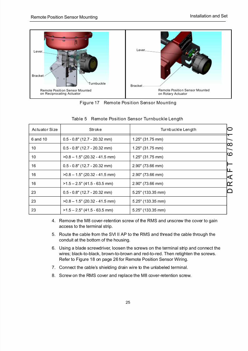
4. Remove the M8 cover-retention screw of the RMS and unscrew the cover to gain
access to the terminal strip.
5. Route the cable from the SVI II AP to the RMS and thread the cable through the
conduit at the bottom of the housing.
6. Using a blade screwdriver, loosen the screws on the terminal strip and connect the
wires; black-to-black, brown-to-brown and red-to-red. Then retighten the screws.
Refer to Figure 18 on page 26 for Remote Position Sensor Wiring.
7. Connect the cable’s shielding drain wire to the unlabeled terminal.
8. Screw on the RMS cover and replace the M8 cover-retention screw.
Table 5 Remote Position Sensor Turnbuckle Length
Actuator Size Stroke Turnbuckle Length
6 and 10 0.5 - 0.8" (12.7 - 20.32 mm) 1.25" (31.75 mm)
10 0.5 - 0.8" (12.7 - 20.32 mm) 1.25" (31.75 mm)
10 >0.8 – 1.5" (20.32 - 41.5 mm) 1.25" (31.75 mm)
16 0.5 - 0.8" (12.7 - 20.32 mm) 2.90" (73.66 mm)
16 >0.8 – 1.5" (20.32 - 41.5 mm) 2.90" (73.66 mm)
16 >1.5 – 2.5" (41.5 - 63.5 mm) 2.90" (73.66 mm)
23 0.5 - 0.8" (12.7 - 20.32 mm) 5.25" (133.35 mm)
23 >0.8 – 1.5" (20.32 - 41.5 mm) 5.25" (133.35 mm)
23 >1.5 – 2.5" (41.5 - 63.5 mm) 5.25" (133.35 mm)
Remote Position Sensor Mounted Remote Position Sensor Mounted
Lever
Bracket
Turnbuckle
on Reciprocating Actuator on Rotary Actuator
Lever
Bracket
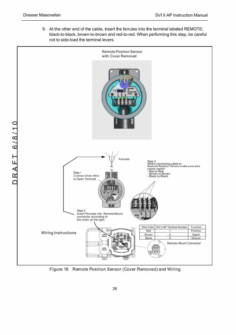
5/8/2018 EW2002 AP 0610 Web_SVI2Ap With Remote Sensor - slidepdf.com
http://slidepdf.com/reader/full/ew2002-ap-0610-websvi2ap-with-remote-sensor 38/160
SVI II AP Instruction Manual
26
D R
A F T
6 / 8 / 1 0
Dresser Masoneilan
9. At the other end of the cable, insert the ferrules into the terminal labeled REMOTE ;
black-to-black, brown-to-brown and red-to-red. When performing this step, be careful
not to side-load the terminal levers.
Figure 18 Remote Position Sensor (Cover Removed) and Wiring
Step 1
Connect Drain Wireto Open Terminal
Step 2When connecting cable toRemote Position Sensor make sure wirecolors match:- Red to Red- Brown to Brown- Black to Black
Step 3Insert Ferrules into Remote Mountconnector according to
Wire Color
Red
BrownBlack
1
23
Positive
SignalGround
the chart at the right:
Remote Mount Connector
Remote Position Sensor
with Cover Removed
Wiring Instructions
FunctionSVI II AP Terminal Number
Ferrules
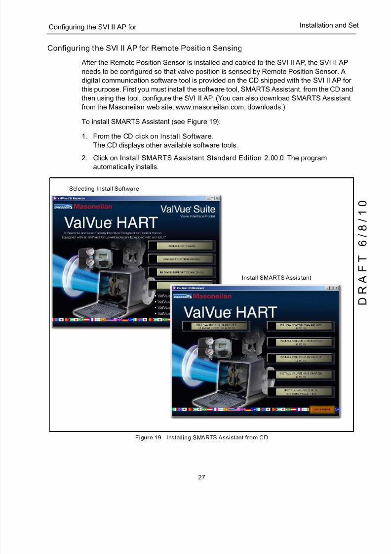
5/8/2018 EW2002 AP 0610 Web_SVI2Ap With Remote Sensor - slidepdf.com
http://slidepdf.com/reader/full/ew2002-ap-0610-websvi2ap-with-remote-sensor 39/160
27
Configuring the SVI II AP for Installation and Se
Configuring the SVI II AP for Remote Position Sensing
After the Remote Position Sensor is installed and cabled to the SVI II AP, the SVI II AP
needs to be configured so that valve position is sensed by Remote Position Sensor. A
digital communication software tool is provided on the CD shipped with the SVI II AP for
this purpose. First you must install the software tool, SMARTS Assistant, from the CD and
then using the tool, configure the SVI II AP. (You can also download SMARTS Assistantfrom the Masoneilan web site, www.masoneilan.com, downloads.)
To install SMARTS Assistant (see Figure 19):
1. From the CD click on Install Software.
The CD displays other available software tools.
2. Click on Install SMARTS Assistant Standard Edition 2.00.0. The program
automatically installs.
Figure 19 Installing SMARTS Assistant from CD
Selecting Install Software
Install SMARTS Assistant

5/8/2018 EW2002 AP 0610 Web_SVI2Ap With Remote Sensor - slidepdf.com
http://slidepdf.com/reader/full/ew2002-ap-0610-websvi2ap-with-remote-sensor 40/160
SVI II AP Instruction Manual
28
D R
A F T
6 / 8 / 1 0
Dresser Masoneilan
Configuring the SVI II AP Using SMARTS Assistant
To configure the SVI II AP:
1. Start SMARTS Assistant Standard by clicking the desktop icon or by selecting the
program through the Start menu.
The Connection screen appears.2. Click on Connection (Figure 20).
SMARTS Assistant searches for the SVI II AP to which the Remote Position Sensor is
connected, connects the device to the software and device information appears
(Figure 20).
3. Select the Options tab and the screen appears (Figure 20).
4. Select the Remote PO checkbox.
5. Activate the Remote Position Sensor by clicking Change Options.
SMARTS Assistant changes control to the Remote Position Sensor and the message
appears.6. Click OK to continue.
Figure 20 SMARTS Assistant - Commissioning the Remote Position Sensor
SMARTS Assistant Connection Screen
SMARTS Device Connected
Options Screen - Remote Position Sensor Selected
Device Set to Use Remote Position Sensor Message
5/8/2018 EW2002 AP 0610 Web_SVI2Ap With Remote Sensor - slidepdf.com
http://slidepdf.com/reader/full/ew2002-ap-0610-websvi2ap-with-remote-sensor 41/160
29
Connecting the Tubing and Air Installation and Se
Connecting the Tubing and Air Supply
The last step in hardware installation for the SVI II AP is to connect the air supply to the
positioner. This section describes the process for connecting the tubing and air supply to
a single and double acting positioner.
WARNING Isolate the valve from the process and disconnect air tubing from the positioner. Disconnect air fully to avoid injury or process damage.
1. Install the tubing to the air supply port (S).
2. For a single acting actuator - pipe the outbound air from the output pressure port (I )
to the actuator.
3. For a double acting actuator - pipe output pressure port one (I ) for one side of the
actuator and output pressure port two (II ) for the other side of the actuator.
4. Air supply:
q Supply pressure for single acting SVI II AP:
20 -100 psi (1.4 - 6.9 bar) (138 - 690 kPa)
q Supply pressure for double acting SVI II AP:
25 - 150 psi (1.73 - 10.4 bar) (0 - 1035 kPa)
q Minimum tubing diameter 1 ⁄ 4" (6mmx4mm)
NOTE The SVI II AP Digital Positioner is designed to operate with clean, dry, oil-free, instrument grade air to ANSI-ISA-57.3
1975 (R1981) or ISA-S7.3-1975 (R1981) or with a sweet natural gas supply (SVI II AP models SVI II AP-2 through SVI II AP-3).
CAUTION Do not use pipe thread sealant tape on pneumatic fittings. It may shred into small particles that can cause instrument malfunction.
Table 6 Air Supply Requirements
Dew Point At least 18° F (10° C) below minimum anticipated ambient temperature
Particulate Matter Filtered to 5 microns
Oil Content Less than 1 ppm w/w
Contaminants Free of all corrosive contaminants
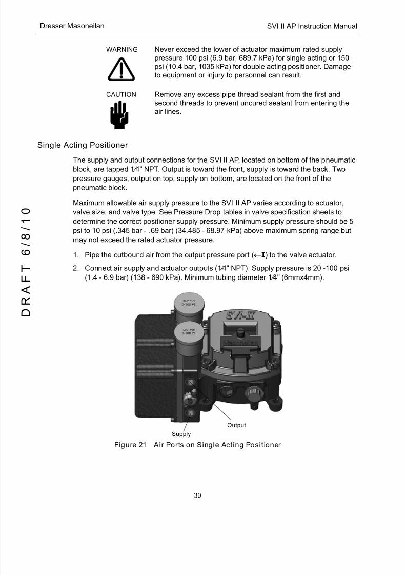
5/8/2018 EW2002 AP 0610 Web_SVI2Ap With Remote Sensor - slidepdf.com
http://slidepdf.com/reader/full/ew2002-ap-0610-websvi2ap-with-remote-sensor 42/160
SVI II AP Instruction Manual
30
D R
A F T
6 / 8 / 1 0
Dresser Masoneilan
WARNING Never exceed the lower of actuator maximum rated supply pressure 100 psi (6.9 bar, 689.7 kPa) for single acting or 150 psi (10.4 bar, 1035 kPa) for double acting positioner. Damage to equipment or injury to personnel can result.
CAUTION Remove any excess pipe thread sealant from the first and
second threads to prevent uncured sealant from entering the air lines.
Single Acting Positioner
The supply and output connections for the SVI II AP, located on bottom of the pneumatic
block, are tapped 1 ⁄ 4" NPT. Output is toward the front, supply is toward the back. Two
pressure gauges, output on top, supply on bottom, are located on the front of the
pneumatic block.
Maximum allowable air supply pressure to the SVI II AP varies according to actuator,valve size, and valve type. See Pressure Drop tables in valve specification sheets to
determine the correct positioner supply pressure. Minimum supply pressure should be 5
psi to 10 psi (.345 bar - .69 bar) (34.485 - 68.97 kPa) above maximum spring range but
may not exceed the rated actuator pressure.
1. Pipe the outbound air from the output pressure port (I ) to the valve actuator.
2. Connect air supply and actuator outputs (1 ⁄ 4" NPT). Supply pressure is 20 -100 psi
(1.4 - 6.9 bar) (138 - 690 kPa). Minimum tubing diameter 1 ⁄ 4" (6mmx4mm).
Figure 21 Air Ports on Single Acting Positioner
Output
Supply

5/8/2018 EW2002 AP 0610 Web_SVI2Ap With Remote Sensor - slidepdf.com
http://slidepdf.com/reader/full/ew2002-ap-0610-websvi2ap-with-remote-sensor 43/160
31
Double Acting Positioner Installation and Se
Double Acting Positioner
The Double Acting (DA) relay has a pair of opposed pneumatic outputs. When Output 1
delivers air to one side of the actuator, Output 2 vents air from the opposite side of the
actuator piston. The volume of air trapped in each determines the position of the actuator.
The Action (ATO or ATC) is applied with respect to Output 1. When Output 1 is connectedto deliver air to extend the actuator, the action is ATC, on a down-seating valve.
1. Connect Output 1, labeled ( I ) to the inlet port of the actuator and Output 2 labeled
( I I ) to the opposing actuator port (see Figure 22).
2. Connect air supply and actuator outputs (1 ⁄ 4" NPT). Supply pressure is 25 - 150 psi
(1.4 - 10.4 bar) (138 - 1035 kPa). Minimum tubing diameter 1 ⁄ 4" (6mmx4mm)
Figure 22 Air Ports on Double Acting Positioner
Output I
Supply Output II
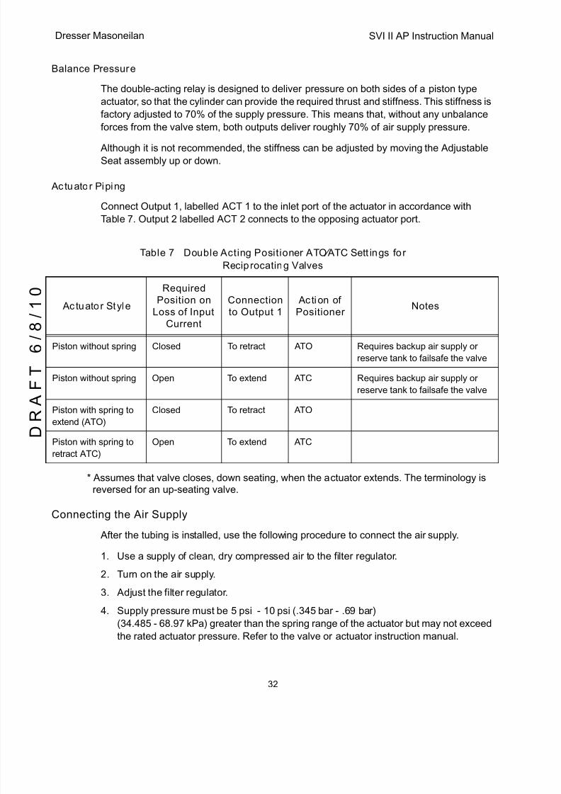
5/8/2018 EW2002 AP 0610 Web_SVI2Ap With Remote Sensor - slidepdf.com
http://slidepdf.com/reader/full/ew2002-ap-0610-websvi2ap-with-remote-sensor 44/160
SVI II AP Instruction Manual
32
D R
A F T
6 / 8 / 1 0
Dresser Masoneilan
Balance Pressure
The double-acting relay is designed to deliver pressure on both sides of a piston type
actuator, so that the cylinder can provide the required thrust and stiffness. This stiffness is
factory adjusted to 70% of the supply pressure. This means that, without any unbalance
forces from the valve stem, both outputs deliver roughly 70% of air supply pressure.
Although it is not recommended, the stiffness can be adjusted by moving the Adjustable
Seat assembly up or down.
Actuator Piping
Connect Output 1, labelled ACT 1 to the inlet port of the actuator in accordance with
Table 7. Output 2 labelled ACT 2 connects to the opposing actuator port.
* Assumes that valve closes, down seating, when the actuator extends. The terminology isreversed for an up-seating valve.
Connecting the Air Supply
After the tubing is installed, use the following procedure to connect the air supply.
1. Use a supply of clean, dry compressed air to the filter regulator.
2. Turn on the air supply.
3. Adjust the filter regulator.
4. Supply pressure must be 5 psi - 10 psi (.345 bar - .69 bar)
(34.485 - 68.97 kPa) greater than the spring range of the actuator but may not exceed
the rated actuator pressure. Refer to the valve or actuator instruction manual.
Table 7 Double Acting Positioner ATO ⁄ ATC Settings for
Reciprocating Valves
Actuator Style
RequiredPosition on
Loss of InputCurrent
Connectionto Output 1
Action ofPositioner
Notes
Piston without spring Closed To retract ATO Requires backup air supply or
reserve tank to failsafe the valve
Piston without spring Open To extend ATC Requires backup air supply or
reserve tank to failsafe the valve
Piston with spring to
extend (ATO)
Closed To retract ATO
Piston with spring to
retract ATC)
Open To extend ATC
5/8/2018 EW2002 AP 0610 Web_SVI2Ap With Remote Sensor - slidepdf.com
http://slidepdf.com/reader/full/ew2002-ap-0610-websvi2ap-with-remote-sensor 45/160
33
Wiring the SVI II AP Installation and Se
Wiring the SVI II AP
The procedure below outlines wiring the SVI II AP.
WARNING q Comply with current national and local regulations for
electrical installation work.
q Comply with national and local explosive atmosphere
regulations.
q Before carrying out any work on the device, power off the
instrument or make sure that the locale conditions for
potentially explosive atmosphere permit the safe opening
of the cover.
Connecting to the Control Loop
The SVI II AP positioner MUST BE grounded according to local regulations. It is
important to maintain correct polarity at all times, otherwise the positioner may notoperate properly. Physically connect the SVI II AP to the control loop using a cable
specified by the HART ® Communication Foundation. A shielded cable is recommended.
To communicate using HART:
1. Connect one end of the cable to the control loop's 4 - 20 mA output.
2. Remove the threaded wiring covers on the positioner.
3. Connect the other end of the cable to the SVI II AP. There are two threaded openings
on the positioner. Use the opening with the red plastic insert.
4. Maintain polarity + and - respectively.
Verify Wiring and Connections
NOTE For split range installations there are additional constraints on the split range system: the minimum span must be 5 mA; the upper range value must be 8 mA to 20 mA; the lower range values must be 4 mA to 14 mA.
Use the following procedure to ensure that the SVI II AP is properly powered:
1. Connect a DC voltmeter across the input terminals.
2. For an input current between 4 and 20 mA, the voltage varies between 11 V and 9 V
respective.
3. Current is read from the local display or with a milliammeter installed in series with the
SVI II AP.
4. When voltage exceeds 11 V check that the polarity is correct.

5/8/2018 EW2002 AP 0610 Web_SVI2Ap With Remote Sensor - slidepdf.com
http://slidepdf.com/reader/full/ew2002-ap-0610-websvi2ap-with-remote-sensor 46/160
SVI II AP Instruction Manual
34
D R
A F T
6 / 8 / 1 0
Dresser Masoneilan
5. If voltage is less than 9 V and polarity is correct, voltage compliance of current source
is inadequate.
6. Connect a milliammeter in series with the current signal. Verify that the source can
supply 20 mA to SVI II AP input.
7. If 20 mA is not attainable, see troubleshooting.
NOTE Improperly or inadequately grounded installations can cause noise or instability in the control loop. The internal electronic components are isolated from ground. Grounding the case is unnecessary for functional purposes but grounding the case may be necessary to conform to local codes.
Wiring Considerations
For a detailed description of wiring guidelines refer to “Wiring Guidelines” on page 80 of
this manual.
5/8/2018 EW2002 AP 0610 Web_SVI2Ap With Remote Sensor - slidepdf.com
http://slidepdf.com/reader/full/ew2002-ap-0610-websvi2ap-with-remote-sensor 47/160
35
3Check Out and Power Up
Overview
This section provides the checkout procedures required to determine if the SVI II AP is in
working order and to power up the unit.Perform all procedures in this section before putting the SVI II AP into operation.
Position Sensor Principles
The motion of the control valve (position) is precisely transmitted to the SVI II AP by a pair of
rotating magnets located outside the instrument housing. Rotation of the magnets is sensed
internally by a Hall Effect sensor. Because the only connection through the case is a
magnetic field there are no seals or bearings to wear or corrode.
The rotation of the magnet is linked to the valve position by the mounting hardware provided.
For a rotary control valve the magnet assembly is normally attached directly to the actuator
shaft. For a reciprocating control valve the mounting kit includes the magnet assembly
mounted in a sealed bearing with a lever that must be linked to the valve stem.
The positioner must be installed with the gauges to the left and the housing display and cover
to the right. The ½ NPT conduit entries must be facing down to drain condensate away from
the housing. The positioner can be moved on the valve for best drainage depending on theposition of the valve in the pipeline.
NOTE
5/8/2018 EW2002 AP 0610 Web_SVI2Ap With Remote Sensor - slidepdf.com
http://slidepdf.com/reader/full/ew2002-ap-0610-websvi2ap-with-remote-sensor 48/160
SVI II AP Instruction Manual
36
D R
A F T
6 / 8 / 1 0
Dresser Masoneilan
Check Out Procedures
SVI II AP checkout consists of physical and operational checkout procedures. The
physical checkout procedures are listed below:
q Inspect the Actuator, Linkages, or Rotary Adapter
q Verify the Mounting and Linkage Adjustment
q Check the Magnet
q Check the Air Supply
q Check the Electronic Module Connections
Physical Inspection
SVI II AP checkout consists of physical and operational checkout procedures. The
physical checkout procedures are listed below:
q Inspect the Actuator, Linkages, or Rotary Adapter
q Verify the Mounting and Linkage Adjustment
q Check the Magnet
q Check the Air Supply
q Check the Electronic Module Connections
q Valve Mounting
q The Air Supply
Actuator, Linkages, or Rotary Adapter
Verify that the mounting has not been damaged in shipment for a pre-mounted SVI II AP,
physically inspect the actuator, linkage. Record the following information for the
configuration checkout:
1. Valve Air to Open (ATO) or
2. Air to Close (ATC)
3. Actuator pressure rating
4. Actuator bench range
5. Inherent trim characteristic of the control valve; linear, equal percentage, or other.
NOTE Refer to the valve data sheet or model number of control valve.
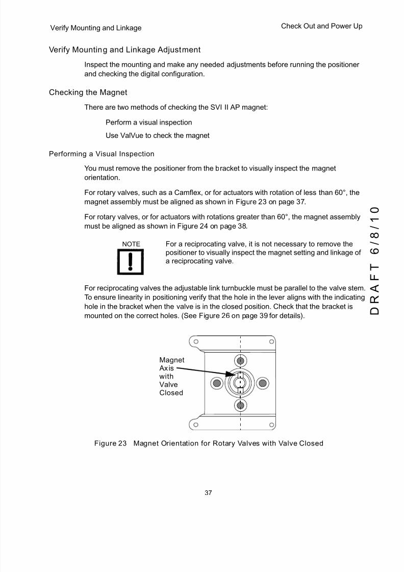
5/8/2018 EW2002 AP 0610 Web_SVI2Ap With Remote Sensor - slidepdf.com
http://slidepdf.com/reader/full/ew2002-ap-0610-websvi2ap-with-remote-sensor 49/160
37
Verify Mounting and Linkage Check Out and Power Up
Verify Mounting and Linkage Adjustment
Inspect the mounting and make any needed adjustments before running the positioner
and checking the digital configuration.
Checking the Magnet
There are two methods of checking the SVI II AP magnet:
q Perform a visual inspection
q Use ValVue to check the magnet
Performing a Visual Inspection
You must remove the positioner from the bracket to visually inspect the magnet
orientation.
For rotary valves, such as a Camflex, or for actuators with rotation of less than 60°, the
magnet assembly must be aligned as shown in Figure 23 on page 37.
For rotary valves, or for actuators with rotations greater than 60°, the magnet assembly
must be aligned as shown in Figure 24 on page 38.
NOTE For a reciprocating valve, it is not necessary to remove the positioner to visually inspect the magnet setting and linkage of a reciprocating valve.
For reciprocating valves the adjustable link turnbuckle must be parallel to the valve stem.
To ensure linearity in positioning verify that the hole in the lever aligns with the indicatinghole in the bracket when the valve is in the closed position. Check that the bracket is
mounted on the correct holes. (See Figure 26 on page 39 for details).
Figure 23 Magnet Orientation for Rotary Valves with Valve Closed
MagnetAxiswithValveClosed
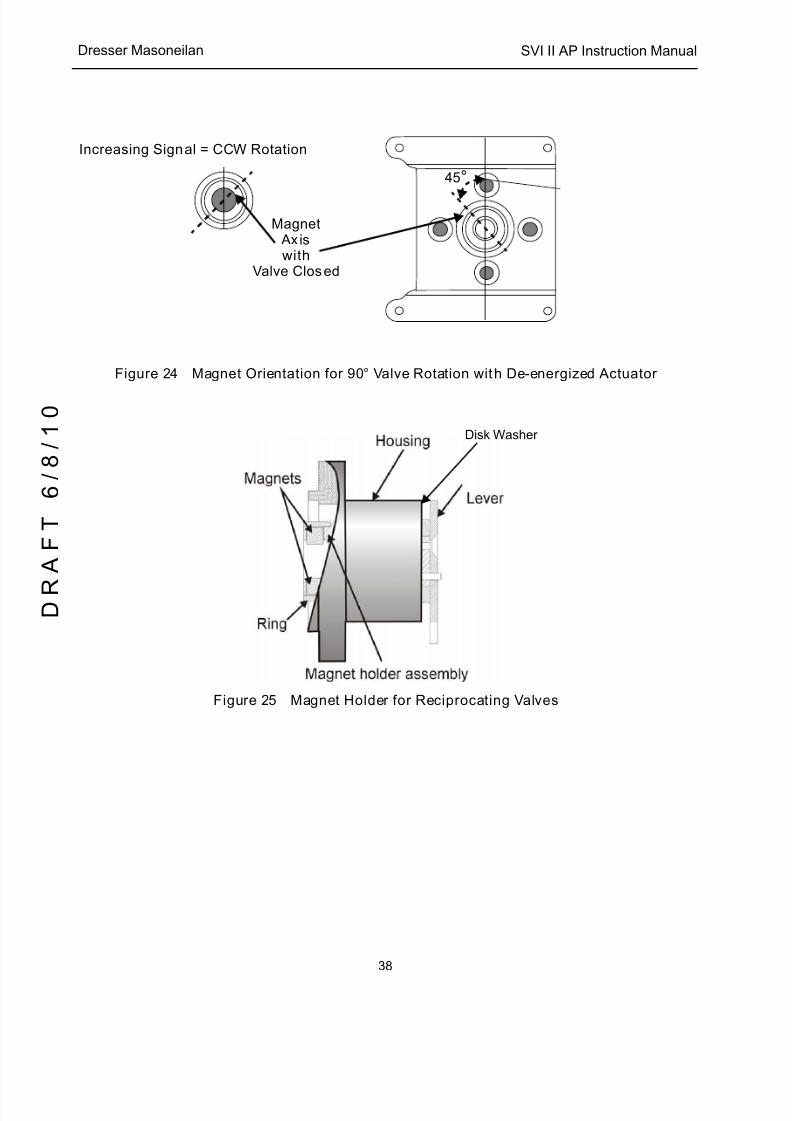
5/8/2018 EW2002 AP 0610 Web_SVI2Ap With Remote Sensor - slidepdf.com
http://slidepdf.com/reader/full/ew2002-ap-0610-websvi2ap-with-remote-sensor 50/160
SVI II AP Instruction Manual
38
D R
A F T
6 / 8 / 1 0
Dresser Masoneilan
Figure 24 Magnet Orientation for 90° Valve Rotation with De-energized Actuator
Figure 25 Magnet Holder for Reciprocating Valves
MagnetAxiswith
Valve Closed
Increasing Signal = CCW Rotation
45°
Disk Washer
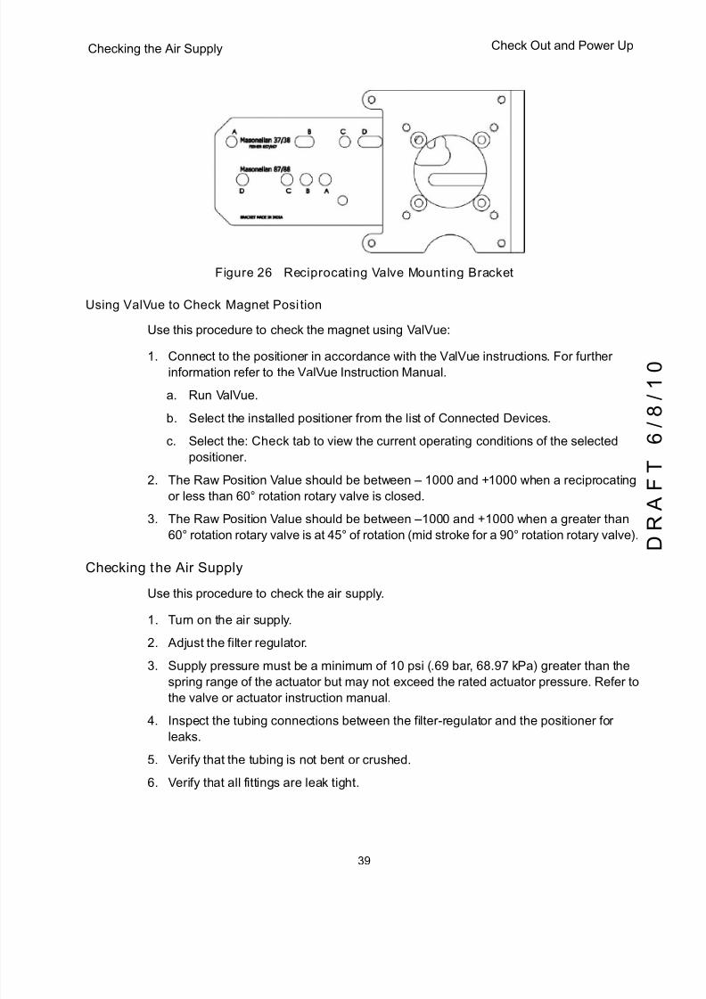
5/8/2018 EW2002 AP 0610 Web_SVI2Ap With Remote Sensor - slidepdf.com
http://slidepdf.com/reader/full/ew2002-ap-0610-websvi2ap-with-remote-sensor 51/160
39
Checking the Air Supply Check Out and Power Up
Figure 26 Reciprocating Valve Mounting Bracket
Using ValVue to Check Magnet Position
Use this procedure to check the magnet using ValVue:
1. Connect to the positioner in accordance with the ValVue instructions. For further
information refer to the ValVue Instruction Manual.
a. Run ValVue.
b. Select the installed positioner from the list of Connected Devices .
c. Select the: Check tab to view the current operating conditions of the selected
positioner.
2. The Raw Position Value should be between – 1000 and +1000 when a reciprocating
or less than 60° rotation rotary valve is closed.
3. The Raw Position Value should be between –1000 and +1000 when a greater than60° rotation rotary valve is at 45° of rotation (mid stroke for a 90° rotation rotary valve).
Checking the Air Supply
Use this procedure to check the air supply.
1. Turn on the air supply.
2. Adjust the filter regulator.
3. Supply pressure must be a minimum of 10 psi (.69 bar, 68.97 kPa) greater than the
spring range of the actuator but may not exceed the rated actuator pressure. Refer to
the valve or actuator instruction manual.
4. Inspect the tubing connections between the filter-regulator and the positioner for
leaks.
5. Verify that the tubing is not bent or crushed.
6. Verify that all fittings are leak tight.

5/8/2018 EW2002 AP 0610 Web_SVI2Ap With Remote Sensor - slidepdf.com
http://slidepdf.com/reader/full/ew2002-ap-0610-websvi2ap-with-remote-sensor 52/160
SVI II AP Instruction Manual
40
D R
A F T
6 / 8 / 1 0
Dresser Masoneilan
CAUTION Do not use Teflon ® pipe seal tape as it can shred into particles harmful to the pneumatic components.
Checking the Electronic Module Connections
WARNING Do not remove the instrument cover or connect to an electrical circuit in a Hazardous Area unless the power is disconnected.
The SVI II AP terminal board has terminal blocks with cage clamp connectors. Not all
options are available for every model. Refer to Table 8 for available functionality.
1. Confirm that all applicable connections to the electronics module connectors are
correct.
Table 8 SVI II AP Models and Functionality
Available Functionality Positioner Model Number
SVI II AP-2 SVI II AP-3
4 - 20 mA Input Setpoint
Display/ Pushbuttons Optional Optional
Remote Mount Input
Process Variable 1 - 5 VDC
SW #1 and #2 Optional Optional
4 - 20 mA Out Position Tx Optional Optional
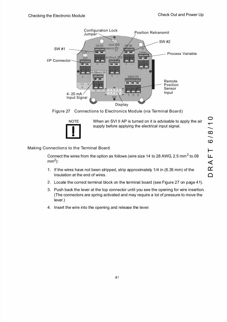
5/8/2018 EW2002 AP 0610 Web_SVI2Ap With Remote Sensor - slidepdf.com
http://slidepdf.com/reader/full/ew2002-ap-0610-websvi2ap-with-remote-sensor 53/160
41
Checking the Electronic Module Check Out and Power Up
Figure 27 Connections to Electronics Module (via Terminal Board)
NOTE When an SVI II AP is turned on it is advisable to apply the air supply before applying the electrical input signal.
Making Connections to the Terminal Board
Connect the wires from the option as follows (wire size 14 to 28 AWG, 2.5 mm2 to.08
mm2):
1. If the wires have not been stripped, strip approximately 1/4 in (6.35 mm) of theinsulation at the end of wires.
2. Locate the correct terminal block on the terminal board (see Figure 27 on page 41).
3. Push back the lever at the top connector until you see the opening for wire insertion.
(The connectors are spring activated and may require a lot of pressure to move the
lever.)
4. Insert the wire into the opening and release the lever.
Display
Remote
Process Variable
Position Retransmit
I/P Connector
PositionSensor
Configuration LockJumper
4- 20 mAInput Signal
SW #1
SW #2
Input

5/8/2018 EW2002 AP 0610 Web_SVI2Ap With Remote Sensor - slidepdf.com
http://slidepdf.com/reader/full/ew2002-ap-0610-websvi2ap-with-remote-sensor 54/160
SVI II AP Instruction Manual
42
D R
A F T
6 / 8 / 1 0
Dresser Masoneilan
Operational Checkout
The operational checkout of the SVI II AP consists of:
1. Connecting the SVI II AP to a current source.
2. Powering up the SVI II AP.3. Checking the pushbutton locks.
Connecting to the Current Source
Connect to a DC mA current source then check and configure with the local display and
pushbuttons, if so equipped. The following section describes configuration and calibration
with the optional local display and pushbuttons. If the SVI II AP is not equipped with local
display use ValVue Lite and a PC with a HART modem or a HART Handheld
Communicator.
NOTE When an SVI II AP is turned on it is advisable to apply the air supply before applying the electrical input signal.
Powering Up the SVI II AP
WARNING This process can cause the valve to move. Before proceeding be sure the valve is isolated from the process. Keep hands clear from moving parts.
NOTE When an SVI II AP is turned on it is advisable to apply the air supply before applying the electrical input signal.
CAUTION Use of a low impedance voltage source damages the SVI II AP. The SVI II AP input must be a current controlled source.The SVI II AP will not function normally if connected directly to a voltage source. However, direct connection to a current source of up to 30 V will not the damage the SVI II AP. A
proper current source explicitly enables adjustment of the current in mA, not Volts.
To power up the SVI II AP:
1. Loosen the four (4) cover screws and remove the SVI II AP cover.
2. Connect the + ⁄ - terminals from the SVI II AP to the current source. Connect + to + and
- to - (Figure 27 on page 41).
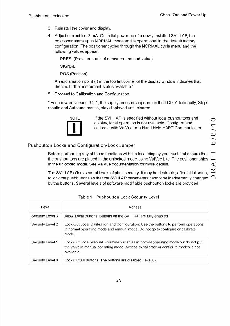
5/8/2018 EW2002 AP 0610 Web_SVI2Ap With Remote Sensor - slidepdf.com
http://slidepdf.com/reader/full/ew2002-ap-0610-websvi2ap-with-remote-sensor 55/160
43
Pushbutton Locks and Check Out and Power Up
3. Reinstall the cover and display.
4. Adjust current to 12 mA. On initial power up of a newly installed SVI II AP, the
positioner starts up in NORMAL mode and is operational in the default factory
configuration. The positioner cycles through the NORMAL cycle menu and the
following values appear:
q PRES: (Pressure - unit of measurement and value)
q SIGNAL
q POS (Position)
An exclamation point (!) in the top left corner of the display window indicates that
there is further instrument status available.*
5. Proceed to Calibration and Configuration.
* For firmware version 3.2.1, the supply pressure appears on the LCD. Additionally, Stops
results and Autotune results, stay displayed until cleared.
NOTE If the SVI II AP is specified without local pushbuttons and display, local operation is not available. Configure and calibrate with ValVue or a Hand Held HART Communicator.
Pushbutton Locks and Configuration-Lock Jumper
Before performing any of these functions with the local display you must first ensure that
the pushbuttons are placed in the unlocked mode using ValVue Lite. The positioner ships
in the unlocked mode. See ValVue documentation for more details.
The SVI II AP offers several levels of plant security. It may be desirable, after initial setup,
to lock the pushbuttons so that the SVI II AP parameters cannot be inadvertently changed
by the buttons. Several levels of software modifiable pushbutton locks are provided.
Table 9 Pushbutton Lock Security Level
Level Access
Security Level 3 Allow Local Buttons: Buttons on the SVI II AP are fully enabled.
Security Level 2 Lock Out Local Calibration and Configuration: Use the buttons to perform operations
in normal operating mode and manual mode. Do not go to configure or calibrate
mode.
Security Level 1 Lock Out Local Manual: Examine variables in normal operating mode but do not put
the valve in manual operating mode. Access to calibrate or configure modes is not
available.
Security Level 0 Lock Out All Buttons: The buttons are disabled (level 0).
5/8/2018 EW2002 AP 0610 Web_SVI2Ap With Remote Sensor - slidepdf.com
http://slidepdf.com/reader/full/ew2002-ap-0610-websvi2ap-with-remote-sensor 56/160
SVI II AP Instruction Manual
44
D R
A F T
6 / 8 / 1 0
Dresser Masoneilan
Hardware Configuration Lock
Additional security is achieved using the hardware configuration-lock jumper shown in
Figure 27 on page 41. When set to the secure position, by shorting the two-pin header,
configuration and calibration are not possible using the local interface or any HART
communication tool. Pushbuttons, ValVue and HHC 375 are locked out, except to
examine configuration, calibration, and position. This is similar to Security Level 1 shownin the Pushbutton Lock Security Level table.
5/8/2018 EW2002 AP 0610 Web_SVI2Ap With Remote Sensor - slidepdf.com
http://slidepdf.com/reader/full/ew2002-ap-0610-websvi2ap-with-remote-sensor 57/160
45
4Using the Digital Interfaces
Overview
This section describes three ways to communicate, configure, and calibrate the SVI II AP.
The Smart Valve Interface is truly a smart device capable of:
q Streamlining the valve positioning function
q Providing diagnostic information
q Improving precision of process control
q Communicating critical information locally and remotely
The four available communication tools listed below offer increasing levels of functionality.
q Local Display and Push Buttons
q HART Handheld Communicator
q ValVue
q Any HART capable Host loaded with the DD for the SVI II AP
Local Display and Pushbuttons
The most basic and easiest digital interface is the local pushbutton and display option
mounted on the SVI II AP. It is available at any time and provides immediate local access to
most configuration, calibration, and fault messages. It is approved for use in Explosion Proof
and Intrinsically Safe installations in Hazardous Areas.
HART Handheld Communicator
The HART handheld communicator is a universally available tool that provides all the
accessibility of the local button and display. The HART tool has the functionality to upload and
download configurations, enter alphanumeric messages and set the custom characteristic
numerical parameters. The HHC 375 is approved for Intrinsically Safe use in Hazardous
Areas in accordance with SVI II AP Approvals and in accordance with the HHC approvals.
See Appendix C and Chapter Six for additional information concerning this device.

5/8/2018 EW2002 AP 0610 Web_SVI2Ap With Remote Sensor - slidepdf.com
http://slidepdf.com/reader/full/ew2002-ap-0610-websvi2ap-with-remote-sensor 58/160
SVI II AP Instruction Manual
46
D R
A F T
6 / 8 / 1 0
Dresser Masoneilan
ValVue
ValVue combines the power of the PC with the features of the SVI II AP for ease of use
and automation of positioner operation and full access to all data. ValVue Lite is provided
with all SVI II AP positioners and is recommended for set up, service and maintenance
where a PC or laptop is permitted. See “Configuring and Calibrating with ValVue” on
page 77 for further information.
Pushbuttons and Local Display
This section covers the optional local interface consisting of the LCD alphanumeric
display and pushbuttons. Operation of the SVI II AP Positioner as a local device is
controlled through the optional device-mounted pushbuttons and digital display, shown in
Figure 28 on page 47. Using the display you can read the input signal, valve position, and
actuator pressure. The display sequences from one variable to the next every 1.5
seconds.
Using the pushbuttons you can exit from operating mode at any time and step through a
menu structure to perform a wide range of manual operation, calibration, configuration,
and monitoring functions that are described later in this section. ValVue is used to perform
all diagnostics functions. The pushbuttons do not support diagnostics functions.
The SVI II AP has two operational modes: Normal (normal operating mode) and Manual
(manual operating mode) and two setup modes, Configuration and Calibration. The SVI II
AP also has two modes for handling of faults and power-up: Reset and Failsafe. When
commissioning or checking a control valve with SVI II AP fully installed the following steps
are recommended:
1. Change mode to Manual mode.2. Examine and adjust all Configuration items.
3. Enter Calibration mode.
4. Run Stops to automatically calibrate stroke.
5. Run Auto Tune to set dynamic response.
6. Examine the device Status.
7. Introduce manual set point changes to verify dynamic performance.
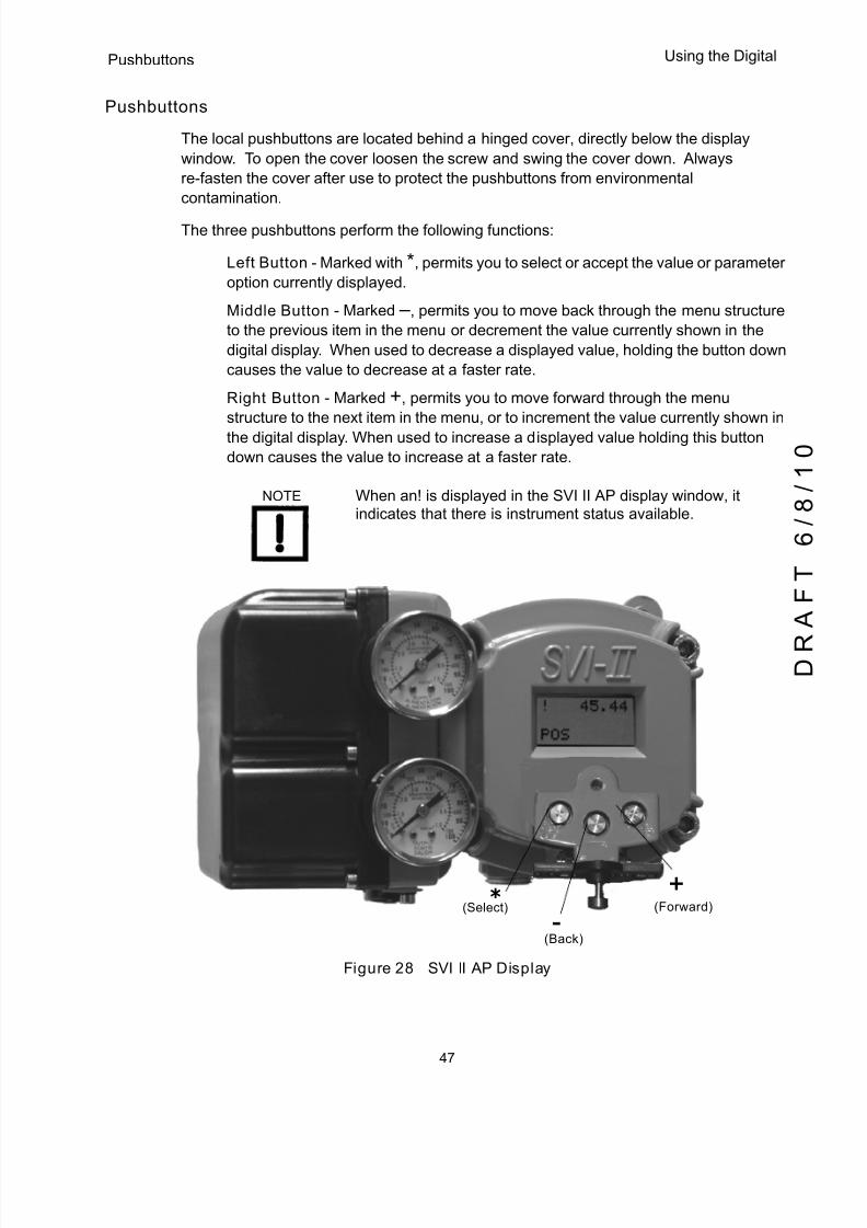
5/8/2018 EW2002 AP 0610 Web_SVI2Ap With Remote Sensor - slidepdf.com
http://slidepdf.com/reader/full/ew2002-ap-0610-websvi2ap-with-remote-sensor 59/160
47
Pushbuttons Using the Digital
Pushbuttons
The local pushbuttons are located behind a hinged cover, directly below the display
window. To open the cover loosen the screw and swing the cover down. Always
re-fasten the cover after use to protect the pushbuttons from environmental
contamination.
The three pushbuttons perform the following functions:
q Left Button - Marked with *, permits you to select or accept the value or parameter
option currently displayed.
q Middle Button - Marked –, permits you to move back through the menu structure
to the previous item in the menu or decrement the value currently shown in the
digital display. When used to decrease a displayed value, holding the button down
causes the value to decrease at a faster rate.
q Right Button - Marked +, permits you to move forward through the menu
structure to the next item in the menu, or to increment the value currently shown in
the digital display. When used to increase a displayed value holding this button
down causes the value to increase at a faster rate.
NOTE When an! is displayed in the SVI II AP display window, it indicates that there is instrument status available.
Figure 28 SVI II AP Display
*+
-(Select) (Forward)
(Back)

5/8/2018 EW2002 AP 0610 Web_SVI2Ap With Remote Sensor - slidepdf.com
http://slidepdf.com/reader/full/ew2002-ap-0610-websvi2ap-with-remote-sensor 60/160
SVI II AP Instruction Manual
48
D R
A F T
6 / 8 / 1 0
Dresser Masoneilan
To determine how to display and select a specific parameter value or configuration option,
refer to the menu structure diagrams shown in Figure 29 on page 49 through Figure 32
on page 56. When using these diagrams as a map you can move through the menus to
the function you needed.
NOTE If the pushbuttons are pushed after being locked by ValVue software, the message LOCKED appears. Refer to the ValVue User’s Guide for instruction about unlocking the pushbuttons.
The following pages display the menu structure for operating the SVI II AP using local
pushbuttons.

5/8/2018 EW2002 AP 0610 Web_SVI2Ap With Remote Sensor - slidepdf.com
http://slidepdf.com/reader/full/ew2002-ap-0610-websvi2ap-with-remote-sensor 61/160
49
Display Menus Using the Digital
Display Menus
NORMAL Operating Mode and MANUAL Mode Menus
When you leave the NORMAL mode to go to MANUAL mode the valve is placed in the
last position it was in when leaving NORMAL. When in the MANUAL mode the device
does not respond to the 4 - 20 mA signal. However, the SVI II AP unit can still respond to
HART commands, including HART commands to position the valve. When you switch to
the VIEW DATA or VIEW ERR menus from the NORMAL operate mode menu the valve is
still in NORMAL mode and still responds to the 4 - 20 mA signal.
Figure 29 NORMAL Operation and MANUAL Menu Structures
NORMAL CyclingMenu NORMAL MANUAL
VIEWDATA VIEW ERR CLR ERR
MANUAL ModeCycling Menu
VIEWDATAMenu
VIEWERRorsMenu
InstantAction
NORMAL MANUALVIEW
DATA
VIEW ERR CLR ERR
MANUAL
SETUPMAN POS
<value>
<value>
* - +
CONFIG
CONFIG CALIB
*
+ + +
+ + + + + +
+
*
*
**
** ** **
any key
++
++++
****
Pressing any display key
*
CALIB
MenuMenu
while in Normal Cycling
moves to Normal mode
*
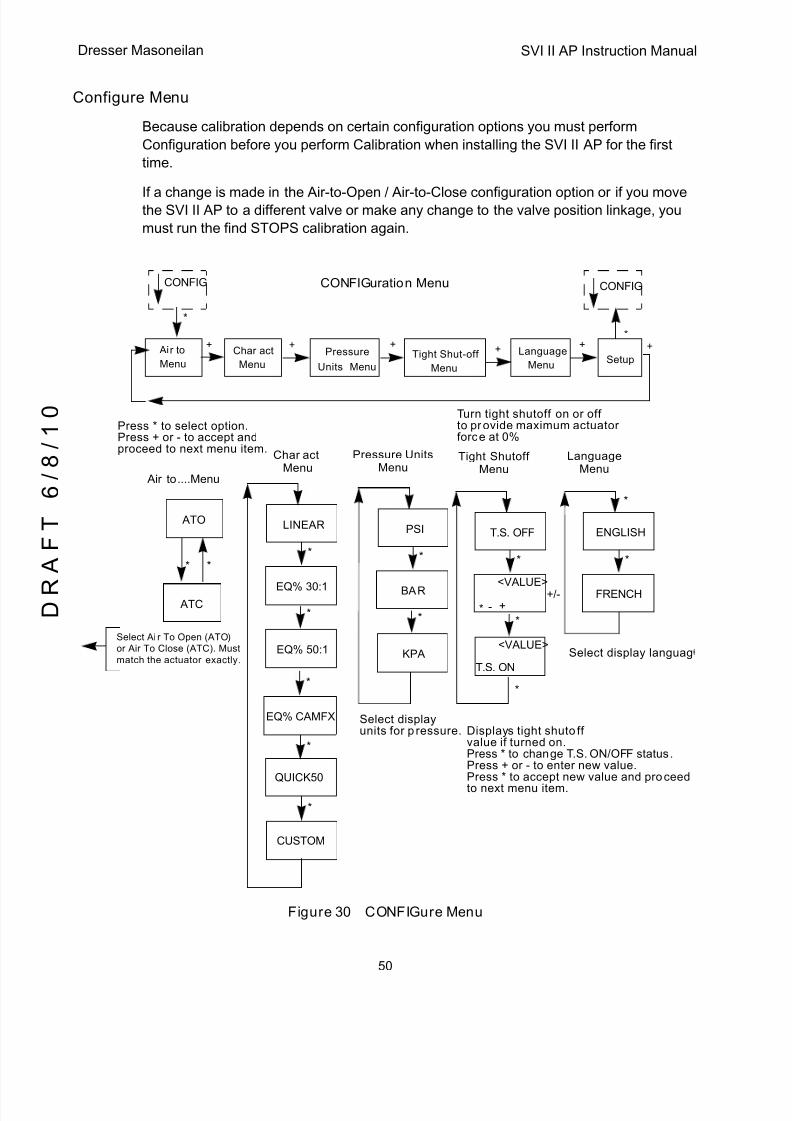
5/8/2018 EW2002 AP 0610 Web_SVI2Ap With Remote Sensor - slidepdf.com
http://slidepdf.com/reader/full/ew2002-ap-0610-websvi2ap-with-remote-sensor 62/160
SVI II AP Instruction Manual
50
D R
A F T
6 / 8 / 1 0
Dresser Masoneilan
Configure Menu
Because calibration depends on certain configuration options you must perform
Configuration before you perform Calibration when installing the SVI II AP for the first
time.
If a change is made in the Air-to-Open / Air-to-Close configuration option or if you movethe SVI II AP to a different valve or make any change to the valve position linkage, you
must run the find STOPS calibration again.
Figure 30 CONFIGure Menu
ATO
Setup
+ ++ ++
*
*
*
Air to....Menu
CONFIGuration Menu
ATC
*
Char act
LINEAR
*
*
EQ% 30:1
*
EQ% 50:1
EQ% CAMFX
QUICK50
*
*
CUSTOM
PSI
*
*
BAR
KPA
T.S. OFF
*
**
*
T.S. ON
ENGLISH
*
*
FRENCH- +
<VALUE>
<VALUE>
+/-
MenuPressure Units
MenuTight Shutoff
MenuLanguage
Menu
Air to
Menu
CONFIG CONFIG
Char act
Menu
Language
MenuTight Shut-off
Menu
Pressure
MenuUnits
+
Displays tight shutoffvalue if turned on.Press * to change T.S. ON/OFF status.Press + or - to enter new value.Press * to accept new value and proceedto next menu item.
Select display languag
Select displayunits for pressure.
Select Air To Open (ATO)or Air To Close (ATC). Mustmatch the actuator exactly.
Turn tight shutoff on or offto provide maximum actuatorforce at 0%
Press * to select option.Press + or - to accept andproceed to next menu item.

5/8/2018 EW2002 AP 0610 Web_SVI2Ap With Remote Sensor - slidepdf.com
http://slidepdf.com/reader/full/ew2002-ap-0610-websvi2ap-with-remote-sensor 63/160
51
Configure Menu Using the Digital
ATO / ATC
WARNING This procedure can cause the valve to move. Before proceeding be sure the valve is isolated from the process.Keep hands clear from moving parts.
The positioner must be configured as Air-to-Open, ATO, or as Air-to-Close, ATC. This
parameter is toggled by the * button. If the positioner has a double acting relay, the action
is defined for the output labeled ACT1, or Output 1.
To determine if a direct acting positioner is considered ATO or ATC perform the following
test:
1. Apply the actuators rated pressure to the positioner supply. Do not exceed actuator
pressure rating on the control valve specification sheet. Damage to the valve stem,
shaft, or trim can occur.
2. Disconnect the electrical (4 to 20 mA) input signal from the positioner or set it to lessthan 3.6 mA.
3. Observe the position of the control valve. If it is closed the actuator is ATO. If the valve
is open it is ATC.
Valve Characteristics
The positioner must be configured to supply the correct relationship between input signal
and valve position. This is called the position characteristic . Figure 10 on page 52 lists
configuring the positioner characteristics.
Use of a linear characteristic is recommended unless the process dynamics or controlvalve application calls for an alternate characteristic. SVI II AP offers a custom
characteristic for specialty applications. Prior to selection of custom, the 10 parameters
for the custom characteristic must be entered using ValVue.
Pressure Units
Select the display units for the optional actuator pressure sensor. The available choices
are PSI, BAR or KPA.
The choice applies to both the local LCD display and to the displays with ValVue or the
HART Handheld communicator.
1. Press * to move from PSI to BAR to KPA.
2. Press + to continue to scroll through the config menu.
NOTE The characteristic configured in the positioner is applied in addition to the plug characteristic built into the valve trim. Do not configure a percentage characteristic if the valve has a percentage plug.
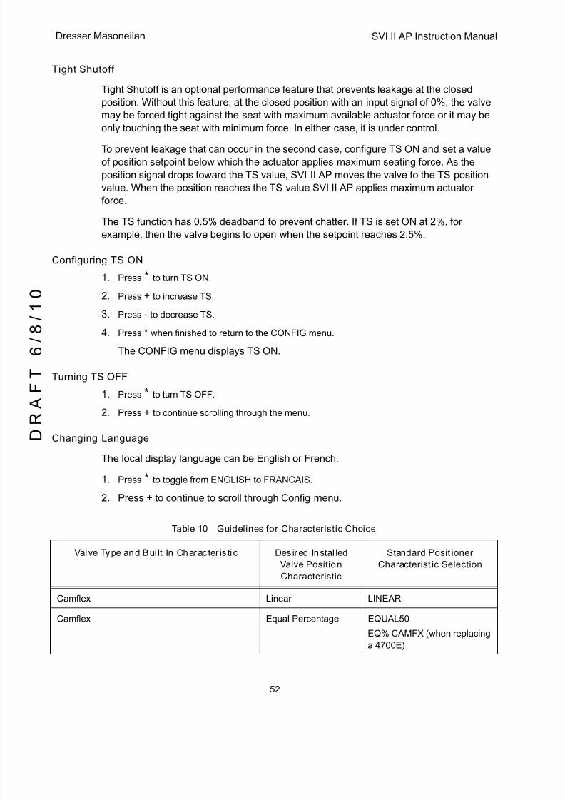
5/8/2018 EW2002 AP 0610 Web_SVI2Ap With Remote Sensor - slidepdf.com
http://slidepdf.com/reader/full/ew2002-ap-0610-websvi2ap-with-remote-sensor 64/160
SVI II AP Instruction Manual
52
D R
A F T
6 / 8 / 1 0
Dresser Masoneilan
Tight Shutoff
Tight Shutoff is an optional performance feature that prevents leakage at the closed
position. Without this feature, at the closed position with an input signal of 0%, the valve
may be forced tight against the seat with maximum available actuator force or it may be
only touching the seat with minimum force. In either case, it is under control.
To prevent leakage that can occur in the second case, configure TS ON and set a value
of position setpoint below which the actuator applies maximum seating force. As the
position signal drops toward the TS value, SVI II AP moves the valve to the TS position
value. When the position reaches the TS value SVI II AP applies maximum actuator
force.
The TS function has 0.5% deadband to prevent chatter. If TS is set ON at 2%, for
example, then the valve begins to open when the setpoint reaches 2.5%.
Configuring TS ON
1. Press * to turn TS ON.
2. Press + to increase TS.
3. Press - to decrease TS.
4. Press * when finished to return to the CONFIG menu.
The CONFIG menu displays TS ON.
Turning TS OFF
1. Press * to turn TS OFF.
2. Press + to continue scrolling through the menu.
Changing Language
The local display language can be English or French.
1. Press * to toggle from ENGLISH to FRANCAIS.
2. Press + to continue to scroll through Config menu.
Table 10 Guidelines for Characteristic Choice
Valve Type and Built In Characteristic Desired Installed
Valve Position
Characteristic
Standard Positioner
Characteristic Selection
Camflex Linear LINEAR
Camflex Equal Percentage EQUAL50
EQ% CAMFX (when replacing
a 4700E)

5/8/2018 EW2002 AP 0610 Web_SVI2Ap With Remote Sensor - slidepdf.com
http://slidepdf.com/reader/full/ew2002-ap-0610-websvi2ap-with-remote-sensor 65/160
53
Configure Menu Using the Digital
Varimax Linear LINEAR
Varimax Equal Percentage EQUAL50
21000 series Model # 21X1X or 41000 series
Model # 41X1X with LINEAR TRIM
Linear LINEAR
21000 series Model # 21X1X or 41000 series
Model # 41X1X with LINEAR TRIM
Equal Percentage EQUAL50
21000 series Model # 21X2X or 41000 series
Model # 41X2X with EQUAL PERCENTAGE
TRIM
Linear Not Recommended
21000 series Model # 21X2X or 41000 series
Model # 41X2X with EQUAL PERCENTAGE
TRIM
Equal Percentage LINEAR
Ball Valve with typical MODIFIED
PERCENTAGE TRIM
Linear Not Recommended
Ball Valve with typical MODIFIED
PERCENTAGE TRIM
Equal Percentage LINEAR
Butterfly valve with typical MODIFIED
PERCENTAGE TRIM
Linear Not Recommended
Butterfly valve with typical MODIFIED
PERCENTAGE TRIM
Equal Percentage LINEAR
Reciprocating valve with LINEAR TRIM Linear LINEAR
Reciprocating valve with LINEAR TRIM Equal Percentage EQUAL50
Rotary or Reciprocating valve with EQUAL
PERCENTAGE TRIM
Linear Not recommended
Rotary or Reciprocating valve with EQUAL
PERCENTAGE TRIM
Equal Percentage LINEAR
Table 10 Guidelines for Characteristic Choice (Continued)
Valve Type and Built In Characteristic Desired Installed
Valve Position
Characteristic
Standard Positioner
Characteristic Selection
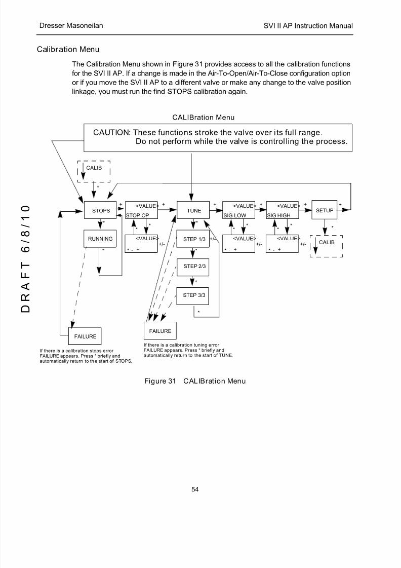
5/8/2018 EW2002 AP 0610 Web_SVI2Ap With Remote Sensor - slidepdf.com
http://slidepdf.com/reader/full/ew2002-ap-0610-websvi2ap-with-remote-sensor 66/160
SVI II AP Instruction Manual
54
D R
A F T
6 / 8 / 1 0
Dresser Masoneilan
Calibration Menu
The Calibration Menu shown in Figure 31 provides access to all the calibration functions
for the SVI II AP. If a change is made in the Air-To-Open/Air-To-Close configuration option
or if you move the SVI II AP to a different valve or make any change to the valve position
linkage, you must run the find STOPS calibration again.
Figure 31 CALIBration Menu
SETUP+ + +
CALIBration Menu
STOPS
*
*
RUNNING
STOP OP
*
*
TUNE
*
*
*
FAILURE
STEP 1/3
STEP 2/3
+/-
*
CALIB
<VALUE>
* - +
<VALUE>+/-
*
SIG LOW
*
<VALUE>
* - +
<VALUE>+/-
*
*
STEP 3/3
If there is a calibration tuning errorFAILURE appears. Press * briefly andautomatically return to the start of TUNE.
FAILURE
If there is a calibration stops errorFAILURE appears. Press * briefly andautomatically return to the start of STOPS.
SIG HIGH
*
<VALUE>
* - +
<VALUE>+/-
*
+ + +
*
CALIB
CAUTION: These functions stroke the valve over its full range.Do not perform while the valve is controlling the process.
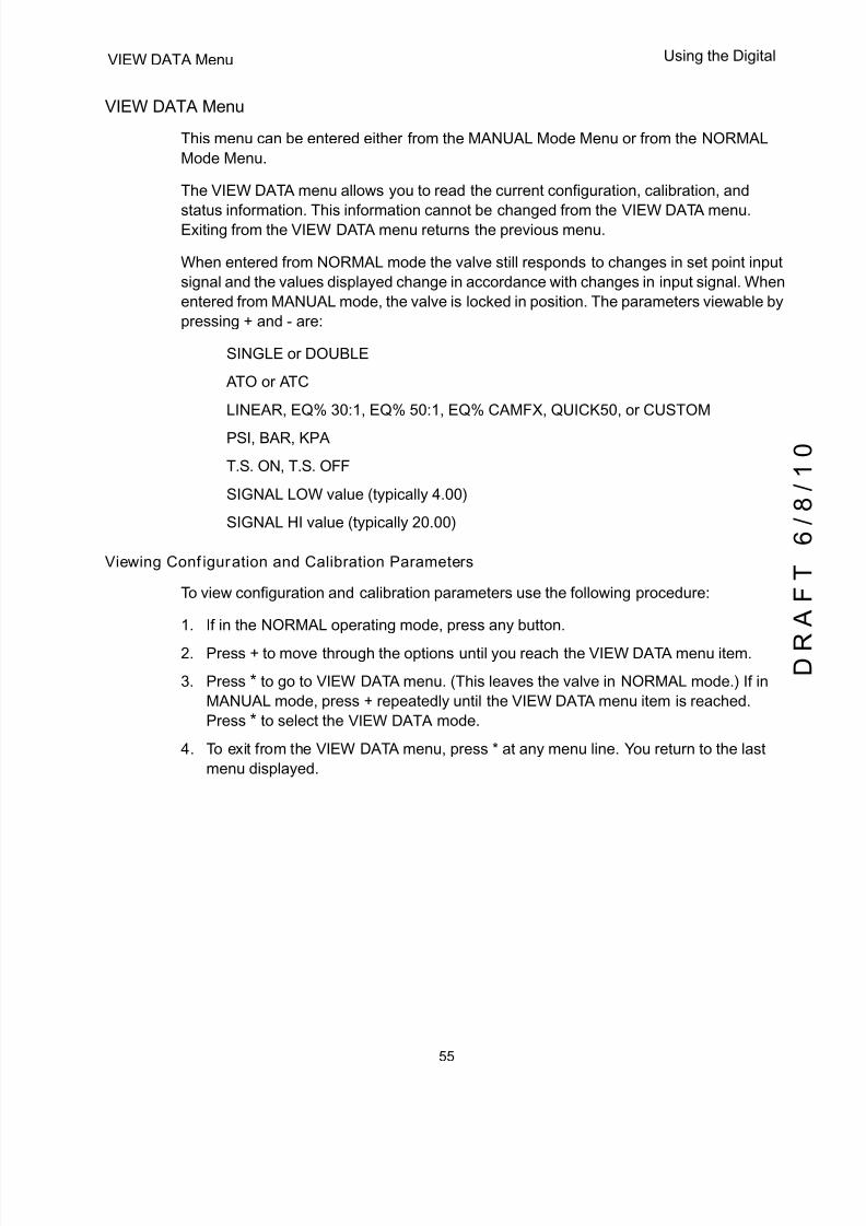
5/8/2018 EW2002 AP 0610 Web_SVI2Ap With Remote Sensor - slidepdf.com
http://slidepdf.com/reader/full/ew2002-ap-0610-websvi2ap-with-remote-sensor 67/160
55
VIEW DATA Menu Using the Digital
VIEW DATA Menu
This menu can be entered either from the MANUAL Mode Menu or from the NORMAL
Mode Menu.
The VIEW DATA menu allows you to read the current configuration, calibration, and
status information. This information cannot be changed from the VIEW DATA menu.Exiting from the VIEW DATA menu returns the previous menu.
When entered from NORMAL mode the valve still responds to changes in set point input
signal and the values displayed change in accordance with changes in input signal. When
entered from MANUAL mode, the valve is locked in position. The parameters viewable by
pressing + and - are:
q SINGLE or DOUBLE
q ATO or ATC
q LINEAR, EQ% 30:1, EQ% 50:1, EQ% CAMFX, QUICK50, or CUSTOM
q PSI, BAR, KPA
q T.S. ON, T.S. OFF
q SIGNAL LOW value (typically 4.00)
q SIGNAL HI value (typically 20.00)
Viewing Configuration and Calibration Parameters
To view configuration and calibration parameters use the following procedure:
1. If in the NORMAL operating mode, press any button.
2. Press + to move through the options until you reach the VIEW DATA menu item.
3. Press * to go to VIEW DATA menu. (This leaves the valve in NORMAL mode.) If in
MANUAL mode, press + repeatedly until the VIEW DATA menu item is reached.
Press * to select the VIEW DATA mode.
4. To exit from the VIEW DATA menu, press * at any menu line. You return to the last
menu displayed.
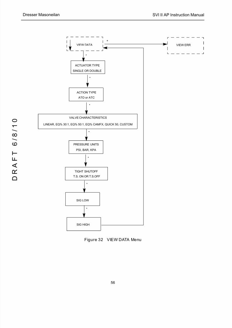
5/8/2018 EW2002 AP 0610 Web_SVI2Ap With Remote Sensor - slidepdf.com
http://slidepdf.com/reader/full/ew2002-ap-0610-websvi2ap-with-remote-sensor 68/160
SVI II AP Instruction Manual
56
D R
A F T
6 / 8 / 1 0
Dresser Masoneilan
Figure 32 VIEW DATA Menu
+
+
SINGLE OR DOUBLE
*
*
PRESSURE UNITS
*
T.S. ON OR T.S.OFF
SIG HIGH
*
VIEW DATA
ACTUATOR TYPE
VALVE CHARACTERISTICS
LINEAR, EQ% 30:1, EQ% 50:1, EQ% CAMFX, QUICK 50, CUSTOM
PSI, BAR, KPA
TIGHT SHUTOFF
ACTION TYPE
SIG LOW
ATO or ATC
*
*
*
VIEW ERR
5/8/2018 EW2002 AP 0610 Web_SVI2Ap With Remote Sensor - slidepdf.com
http://slidepdf.com/reader/full/ew2002-ap-0610-websvi2ap-with-remote-sensor 69/160
57
FAILSAFE Mode Using the Digital
FAILSAFE Mode
FAILSAFE mode cannot be selected from any of the previous menus. FAILSAFE mode
and display are initiated by detection of a critical fault in the positioner or the valve
system. There are two ways to deal with a FAILSAFE condition: correct the problem and
clear the error messages or run through the FAILSAFE menu, view error messages,
enter MANUAL mode and RESET. RESET restarts operation.
When failsafe occurs:
1. Press + to move to VIEW ERR .
2. Press * to view the first error message. Press + to scroll through all the fault
messages in turn.
3. Correct the cause of the problem and press + to move to CLR ERR.
4. Press * to remove all error messages from memory.
5. Move to the MANUAL menu. If you have cleared the errors RESET no longer
appears.
or
1. Press + to move to VIEW ERR .
2. Press * to view the first error message. Press + to scroll through all the fault
messages in turn.
3. Move to MANUAL menu and enter Manual mode.
4. Select RESET to start the valve from its failsafe condition.
5. Identify and correct errors and select RESET to return to the prior mode (without
removing error messages from memory).

5/8/2018 EW2002 AP 0610 Web_SVI2Ap With Remote Sensor - slidepdf.com
http://slidepdf.com/reader/full/ew2002-ap-0610-websvi2ap-with-remote-sensor 70/160
SVI II AP Instruction Manual
58
D R
A F T
6 / 8 / 1 0
Dresser Masoneilan
Figure 33 FAILSAFE Menu
VIEW ERR Diagnostics Messages
Diagnostic messages are viewed with VIEW ERR from the MANUAL Mode Menu or from
NORMAL Mode Menu. The VIEW ERR menu item allows you to read the current status
information.
To clear the error messages:
1. Press * at CLR ERR on either the MANUAL or NORMAL mode menus.
2. Exiting from the VIEW ERR menu returns the previous menu.
RESET
+ +
FAILSAFE Menu
FAILSAFE
*
CLR ERR+ +
VIEW ERR
MANUAL MODE
MANUAL
CYCLING MENU
InstantAction
*
**
Pressing *
displays the first
error, pressing a second time
displays the second error.
Keep pressing to see all errors
until VIEW ERR appears.
WAITQuickly Flashes

5/8/2018 EW2002 AP 0610 Web_SVI2Ap With Remote Sensor - slidepdf.com
http://slidepdf.com/reader/full/ew2002-ap-0610-websvi2ap-with-remote-sensor 71/160
59
VIEW ERR Diagnostics Messages Using the Digital
Table 11 Error Messages
LCD Description Action Cause
RESET Reset occurred due to command or power up. Always
present after power up.
Warning Normal operation
on power upalways sets
RESET. RESET is
sent by HART
communications.
Use CLEAR ERR
to remove warning
LOW
POWER
Input current < 3.6 mA Takes the device
to low power
ACT ERR Positioner unable to position a valve normally Warning
AIR LOW Supply pressure option is configured and supply
pressure is < 10 psi (.69 bar, 69 kPa). Otherwise I/P
pressure is below 0.8 psi (.05 bar, 5.5 kPa)
Warning Mechanical or
pneumatic problem
POS ERR The position error exceeds configured limit for more
than configured time
Warning after T1
and Failsafe
Pneumatic/
mechanical,
configuration,
loose magnet
KEYBOARD LCD/Button Failure Warning Damaged buttons
or LCD electronics
MARGNPWR
Input signal is insufficient to proceed
CALIB ERR Calibrate failed Warning Invalid values for
current calibration
and input range by
HART commands
STOP ERR Calibration error. Find STOPS was unsuccessful. Warning Configuration,
calibration
TUNE ERR Auto tune failed Warning Mechanical or
pneumatic problem
causes tuningfailure
STD DIAG A standard diagnostic procedure failed to complete Warning Pneumatic /
mechanical,
configuration
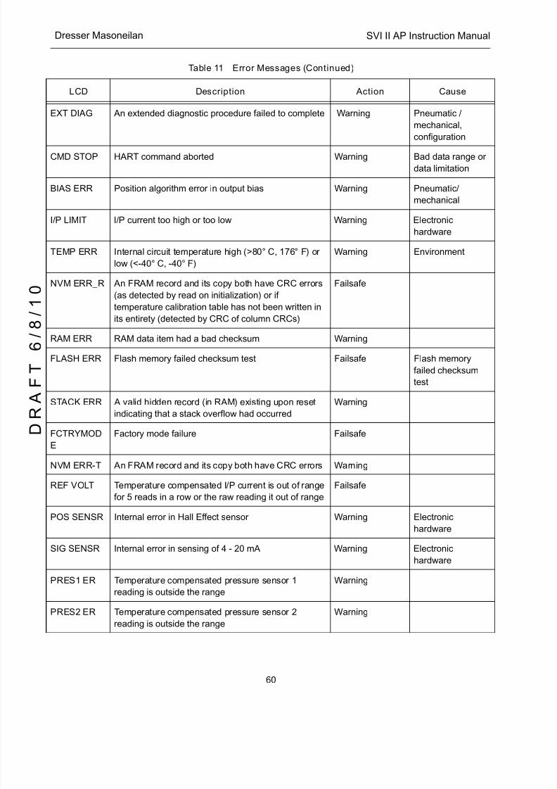
5/8/2018 EW2002 AP 0610 Web_SVI2Ap With Remote Sensor - slidepdf.com
http://slidepdf.com/reader/full/ew2002-ap-0610-websvi2ap-with-remote-sensor 72/160
SVI II AP Instruction Manual
60
D R
A F T
6 / 8 / 1 0
Dresser Masoneilan
EXT DIAG An extended diagnostic procedure failed to complete Warning Pneumatic /
mechanical,
configuration
CMD STOP HART command aborted Warning Bad data range or
data limitation
BIAS ERR Position algorithm error in output bias Warning Pneumatic/
mechanical
I/P LIMIT I/P current too high or too low Warning Electronic
hardware
TEMP ERR Internal circuit temperature high (>80° C, 176° F) or
low (<-40° C, -40° F)
Warning Environment
NVM ERR_R An FRAM record and its copy both have CRC errors
(as detected by read on initialization) or if
temperature calibration table has not been written in
its entirety (detected by CRC of column CRCs)
Failsafe
RAM ERR RAM data item had a bad checksum Warning
FLASH ERR Flash memory failed checksum test Failsafe Flash memory
failed checksum
test
STACK ERR A valid hidden record (in RAM) existing upon reset
indicating that a stack overflow had occurred
Warning
FCTRYMOD
E
Factory mode failure Failsafe
NVM ERR-T An FRAM record and its copy both have CRC errors Warning
REF VOLT Temperature compensated I/P current is out of range
for 5 reads in a row or the raw reading it out of range
Failsafe
POS SENSR Internal error in Hall Effect sensor Warning Electronic
hardware
SIG SENSR Internal error in sensing of 4 - 20 mA Warning Electronichardware
PRES1 ER Temperature compensated pressure sensor 1
reading is outside the range
Warning
PRES2 ER Temperature compensated pressure sensor 2
reading is outside the range
Warning
Table 11 Error Messages (Continued)
LCD Description Action Cause
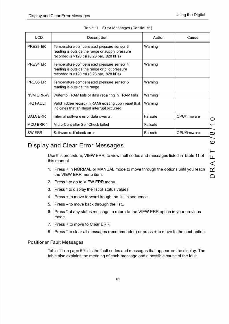
5/8/2018 EW2002 AP 0610 Web_SVI2Ap With Remote Sensor - slidepdf.com
http://slidepdf.com/reader/full/ew2002-ap-0610-websvi2ap-with-remote-sensor 73/160
61
Display and Clear Error Messages Using the Digital
Display and Clear Error Messages
Use this procedure, VIEW ERR, to view fault codes and messages listed in Table 11 of
this manual.
1. Press + in NORMAL or MANUAL mode to move through the options until you reachthe VIEW ERR menu item.
2. Press * to go to VIEW ERR menu.
3. Press * to display the list of status values.
4. Press + to move forward trough the list in sequence.
5. Press – to move back through the list,.
6. Press * at any status message to return to the VIEW ERR option in your previous
mode.
7. Press + to move to Clear ERR .8. Press * to clear all messages (recommended) or press + to move to the next option.
Positioner Fault Messages
Table 11 on page 59 lists the fault codes and messages that appear on the display. The
table also explains the meaning of each message and a possible cause of the fault.
PRES3 ER Temperature compensated pressure sensor 3
reading is outside the range or supply pressure
recorded is >120 psi (8.28 bar, 828 kPa)
Warning
PRES4 ER Temperature compensated pressure sensor 4
reading is outside the range or pilot pressure
recorded is >120 psi (8.28 bar, 828 kPa)
Warning
PRES5 ER Temperature compensated pressure sensor 5
reading is outside the range
Warning
NVM ERR-W Writer to FRAM fails or data repairing in FRAM fails Warning
IRQ FAULT Valid hidden record (in RAM) existing upon reset that
indicates that an illegal interrupt occurred
Warning
DATA ERR Internal software error data overrun Failsafe CPU/firmware
MCU ERR 1 Micro-Controller Self Check failed Failsafe
SW ERR Software self check error Failsafe CPU/firmware
Table 11 Error Messages (Continued)
LCD Description Action Cause
5/8/2018 EW2002 AP 0610 Web_SVI2Ap With Remote Sensor - slidepdf.com
http://slidepdf.com/reader/full/ew2002-ap-0610-websvi2ap-with-remote-sensor 74/160
SVI II AP Instruction Manual
62
D R
A F T
6 / 8 / 1 0
Dresser Masoneilan
Return to Normal Operation
Always return the positioner to NORMAL operating mode to resume control by the input
signal. Use this procedure to return to NORMAL mode from any menu.
1. Press + or - repeatedly until MANUAL or NORMAL appears.
2. Press:
q * to return to NORMAL operating mode, if NORMAL appears.
q * to return to MANUAL Mode menu, if MANUAL appears.
3. Press + repeatedly until -› NORMAL appears.
4. Press * to return to NORMAL mode and normal operation.
NOTE When entered from NORMAL mode the valve still responds to changes in set point input signal and the values displayed change in accordance with changes in the input signal. When
entered from MANUAL mode the valve is in locked position.
Hand Held Communicator
For communication to a HART device, there is a Device Description Language. A Device
Description, DD, is published by registration with the HART Communication Foundation.
When the DD is installed in a host communication device then the host can readily access
all the information in the smart field device. The SVI II AP registered DD will be available
from HART Communication Foundation when it next publishes the HART DD. The SVI II
AP DD can be obtained from Masoneilan or by contacting your local Masoneilan
representative.
CAUTION Do not connect a HART modem and PC to a control circuit unless the controller is HART compatible or has a HART filter.Loss of control or a process upset may occur if the controller output circuit is not compatible with HART signal.
WARNING Do not Connect a PC or HART modem to an intrinsically safe circuit except on the safe area side of the barrier. Do not operate a PC in a hazardous area without compliance to local and plant regulations.
5/8/2018 EW2002 AP 0610 Web_SVI2Ap With Remote Sensor - slidepdf.com
http://slidepdf.com/reader/full/ew2002-ap-0610-websvi2ap-with-remote-sensor 75/160
63
ValVue Using the Digital
ValVue
The third digital interface available for the SVI II AP is Masoneilan’s ValVue software.
ValVue provides a user friendly interface that facilitates set up and operation of the
positioner. ValVue is used to configure, calibrate and perform valve diagnostics with the
SVI II AP utilizing HART communications protocol.The SVI II AP is shipped with a free version of ValVue Lite, that is ready to use without
registration. Please refer to the ValVue Instruction manual included on the ValVue CD
ROM.
Installation of ValVue Software, and Registration
For assistance contact the nearest Masoneilan Dresser Sales Office, your local
Masoneilan representative or email [email protected].
Visit our web page at http:/www.masoneilan.com. ValVue Lite and a 60-day trial version of
ValVue are included with the SVI II AP. Contact the factory to purchase a registeredupgrade to ValVue, or to request ValVue on a CD-ROM.

5/8/2018 EW2002 AP 0610 Web_SVI2Ap With Remote Sensor - slidepdf.com
http://slidepdf.com/reader/full/ew2002-ap-0610-websvi2ap-with-remote-sensor 76/160
SVI II AP Instruction Manual
64
D R
A F T
6 / 8 / 1 0
Dresser Masoneilan
System Requirements
ValVue Lite runs on IBM ® compatible computers. Minimum requirements for all versions
of ValVue software are:
q Windows ® 2000, XP, and Windows Server 2003
q 64 MB RAM
q Hard drive available space 35 MB
q A CD ROM drive
q An available Serial or USB port
q A HART modem and appropriate cables
Install the ValVue software in the PC in accordance with the instructions on the CD-ROM
jacket. After installation select ValVue from the program group, and double click to begin.
See Figure 34, which shows the screen for setting the ValVue options. Be sure to set the
COM port to the serial output connection attached to your PC modem. Checking theAllow Multidrop option (as shown) slows down the search for active devices on single
drop current loops. It is recommended only for split range and multiplexor applications.
Figure 34 ValVue Options
5/8/2018 EW2002 AP 0610 Web_SVI2Ap With Remote Sensor - slidepdf.com
http://slidepdf.com/reader/full/ew2002-ap-0610-websvi2ap-with-remote-sensor 77/160
65
5Configuration and Calibration
Configuration and Calibration
This section provides procedures to:
q View configuration data and status messages for the
SVI II AP
q Configure the SVI II AP
q Calibrate and tune the SVI II AP
Observe all warnings as the valve moves during these procedures.
These procedures can cause the valve to move. Before proceeding be sure the valve is
isolated from the process. Keep hands clear from moving parts.
All configuration and calibration procedures are described using an SVI II
AP with pushbuttons and display and ValVue software.
ValVue Software
The SVI II AP is shipped with a free version of ValVue Lite and a trial version of ValVue.
ValVue Lite
ValVue Lite software is shipped with each SVI II AP for positioner calibration andconfiguration. ValVue Lite software is offered without registration. It provides sufficient
functionality to fully commission, configure, and start up a positioner on a control valve.
NOTE

5/8/2018 EW2002 AP 0610 Web_SVI2Ap With Remote Sensor - slidepdf.com
http://slidepdf.com/reader/full/ew2002-ap-0610-websvi2ap-with-remote-sensor 78/160
SVI II AP Instruction Manual
66
D R
A F T
6 / 8 / 1 0
Dresser Masoneilan
System Requirements
ValVue Lite runs on IBM compatible computers. Minimum requirements for all versions of
ValVue software are Windows 2000, and XP, 64 MB RAM, a serial port connected to a
HART modem, and a CD-ROM drive.
Full Trial Version
The SVI II AP comes with a copy of ValVue Trial Version software that can be used for
sixty days without a license. After the 60-day trial period, ValVue does not execute and
you must register. ValVue, full version, provides advanced diagnostic, maintenance
capabilities and basic calibration and configuration for the SVI II AP. The SVI II AP
performs valve diagnostics and in ValVue displays stroking speed, step response,
cumulative travel, cycles, and operation in near-closed position. The software stores test
results for comparison with future results for predictive maintenance. Password protected
access to remote instruments is set up with administration features. The fully licensed
ValVue software is available as an upgrade.
Pushbuttons and Local Display for Configuration and Calibration
The pushbuttons and local display are thoroughly described in “Using the Digital
Interfaces”, “Pushbuttons and Local Display” on page 46 of this manual.
Pushbuttons Summary
The local pushbuttons are located behind a hinged cover, directly below the display
window. To open the cover loosen the screw and swing the cover down. Always
re-fasten the cover after use to protect the pushbuttons from environmental
contamination.
The three pushbuttons perform the following functions:
q Left Button - Marked with *, permits you to select or accept the value or parameter
option currently displayed.
q Middle Button - Marked –, permits you to move back through the menu structure
to the previous item in the menu or decrement the value currently shown in the
digital display. When used to decrease a displayed value, holding the button down
causes the value to decrease at a faster rate.
q Right Button - Marked +, permits you to move forward through the menu
structure to the next item in the menu, or to increment the value currently shown in
the digital display. When used to increase a displayed value holding this button
down causes the value to increase at a faster rate.
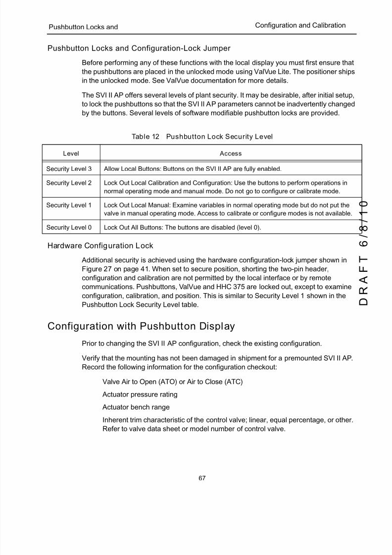
5/8/2018 EW2002 AP 0610 Web_SVI2Ap With Remote Sensor - slidepdf.com
http://slidepdf.com/reader/full/ew2002-ap-0610-websvi2ap-with-remote-sensor 79/160
67
Pushbutton Locks and Configuration and Calibration
Pushbutton Locks and Configuration-Lock Jumper
Before performing any of these functions with the local display you must first ensure that
the pushbuttons are placed in the unlocked mode using ValVue Lite. The positioner ships
in the unlocked mode. See ValVue documentation for more details.
The SVI II AP offers several levels of plant security. It may be desirable, after initial setup,to lock the pushbuttons so that the SVI II AP parameters cannot be inadvertently changed
by the buttons. Several levels of software modifiable pushbutton locks are provided.
Hardware Configuration Lock
Additional security is achieved using the hardware configuration-lock jumper shown in
Figure 27 on page 41. When set to secure position, shorting the two-pin header,
configuration and calibration are not permitted by the local interface or by remote
communications. Pushbuttons, ValVue and HHC 375 are locked out, except to examine
configuration, calibration, and position. This is similar to Security Level 1 shown in the
Pushbutton Lock Security Level table.
Configuration with Pushbutton Display
Prior to changing the SVI II AP configuration, check the existing configuration.
Verify that the mounting has not been damaged in shipment for a premounted SVI II AP.
Record the following information for the configuration checkout:
q Valve Air to Open (ATO) or Air to Close (ATC)
q Actuator pressure rating
q Actuator bench range
q Inherent trim characteristic of the control valve; linear, equal percentage, or other.
Refer to valve data sheet or model number of control valve.
Table 12 Pushbutton Lock Security Level
Level Access
Security Level 3 Allow Local Buttons: Buttons on the SVI II AP are fully enabled.
Security Level 2 Lock Out Local Calibration and Configuration: Use the buttons to perform operations in
normal operating mode and manual mode. Do not go to configure or calibrate mode.
Security Level 1 Lock Out Local Manual: Examine variables in normal operating mode but do not put the
valve in manual operating mode. Access to calibrate or configure modes is not available.
Security Level 0 Lock Out All Buttons: The buttons are disabled (level 0).

5/8/2018 EW2002 AP 0610 Web_SVI2Ap With Remote Sensor - slidepdf.com
http://slidepdf.com/reader/full/ew2002-ap-0610-websvi2ap-with-remote-sensor 80/160
SVI II AP Instruction Manual
68
D R
A F T
6 / 8 / 1 0
Dresser Masoneilan
Viewing Configuration Data
To view SVI II AP configuration data:
1. Access the VIEW DATA menu from the MANUAL menu by pressing the + button.
2. In the VIEW DATA menu, press * to examine the configuration.
3. Press + to scroll through and observe the factory configuration.
4. Press * to exit VIEW DATA.
5. Press + until MANUAL appears.
6. Press * to enter MANUAL mode.
7. Press any key to make MAN POS appear.
8. When the adjustment screen appears stroke the valve open by holding + down.
Notice that the rate of set point change is slow to begin, but increases speed while the
+ is pressed.
9. Stroke the valve to several values.
10. Verify the action is as desired.
11. Press * to exit MAN POS mode.
12. Press + to move to the SETUP menu.
13. In the SETUP menu press the * button to access the CONFIGuration menu.
14. In the CONFIG menu set the configuration parameters.
15. When in CONFIGure or CALIBrate, pressing * changes values.
16. Return to NORMAL mode. The valve moves to the Value set by the current calibrator.
17. Stroke the valve through its range to verify that the movement is as desired.
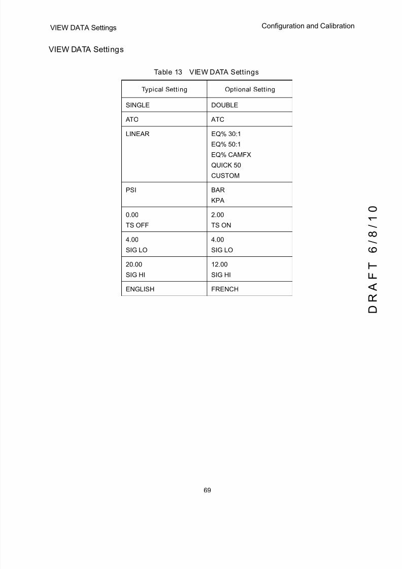
5/8/2018 EW2002 AP 0610 Web_SVI2Ap With Remote Sensor - slidepdf.com
http://slidepdf.com/reader/full/ew2002-ap-0610-websvi2ap-with-remote-sensor 81/160
69
VIEW DATA Settings Configuration and Calibration
VIEW DATA Settings
Table 13 VIEW DATA Settings
Typical Setting Optional Setting
SINGLE DOUBLE
ATO ATC
LINEAR EQ% 30:1
EQ% 50:1
EQ% CAMFX
QUICK 50
CUSTOM
PSI BAR
KPA
0.00
TS OFF
2.00
TS ON
4.00
SIG LO
4.00
SIG LO
20.00
SIG HI
12.00
SIG HI
ENGLISH FRENCH
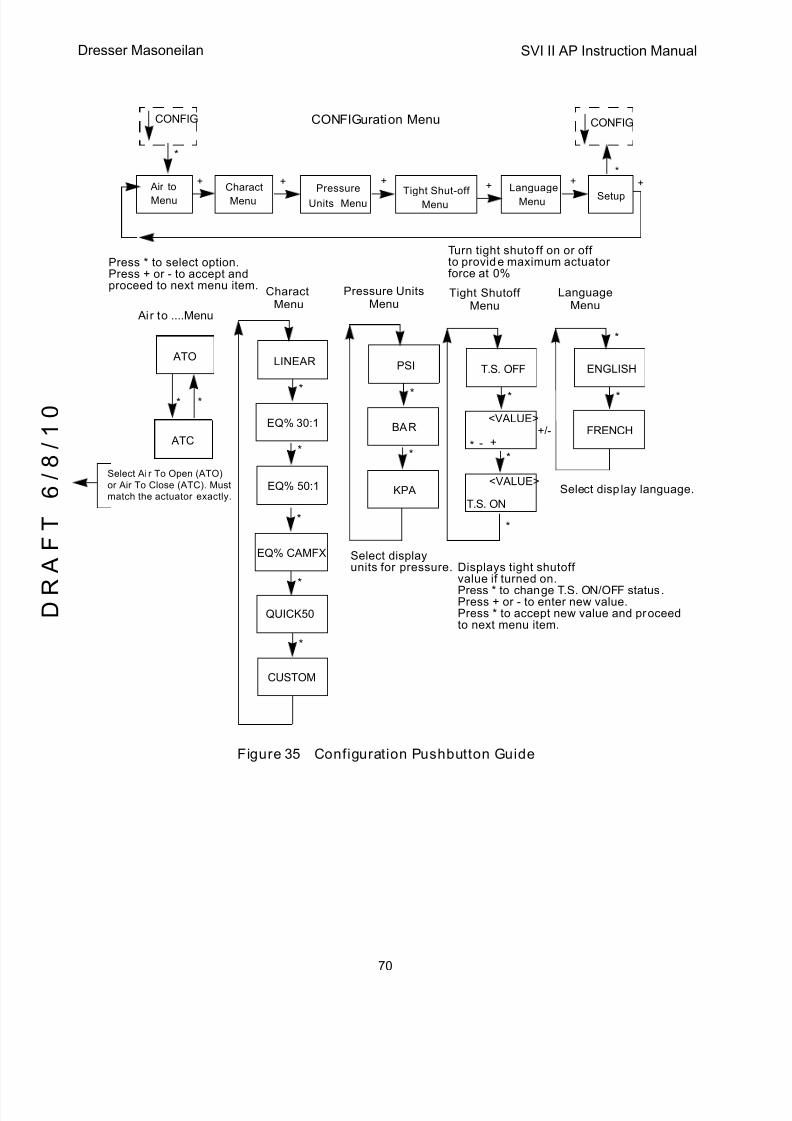
5/8/2018 EW2002 AP 0610 Web_SVI2Ap With Remote Sensor - slidepdf.com
http://slidepdf.com/reader/full/ew2002-ap-0610-websvi2ap-with-remote-sensor 82/160
SVI II AP Instruction Manual
70
D R
A F T
6 / 8 / 1 0
Dresser Masoneilan
Figure 35 Configuration Pushbutton Guide
ATO
Setup
+ ++ ++
*
*
*
Air to ....Menu
CONFIGuration Menu
ATC
*
Charact
LINEAR
*
*
EQ% 30:1
*
EQ% 50:1
EQ% CAMFX
QUICK50
*
*
CUSTOM
PSI
*
*
BAR
KPA
T.S. OFF
*
**
*
T.S. ON
ENGLISH
*
*
FRENCH- +
<VALUE>
<VALUE>
+/-
MenuPressure Units
MenuTight Shutoff
MenuLanguage
Menu
Air to
Menu
CONFIG CONFIG
Charact
Menu
Language
MenuTight Shut-offMenu
Pressure
MenuUnits
+
Displays tight shutoffvalue if turned on.Press * to change T.S. ON/OFF status.Press + or - to enter new value.Press * to accept new value and proceedto next menu item.
Select display language.
Select displayunits for pressure.
Select Air To Open (ATO)or Air To Close (ATC). Mustmatch the actuator exactly.
Turn tight shutoff on or offto provide maximum actuatorforce at 0%
Press * to select option.Press + or - to accept andproceed to next menu item.
5/8/2018 EW2002 AP 0610 Web_SVI2Ap With Remote Sensor - slidepdf.com
http://slidepdf.com/reader/full/ew2002-ap-0610-websvi2ap-with-remote-sensor 83/160
71
Calibration Configuration and Calibration
Calibration
NOTE Always perform configuration before running calibration functions.
CAUTION Pilot Trim Valve Applications require the use of the Manual Stop calibration procedure. Do not run Find Stops or the ValVue Setup Wizard on valves with Pilot Trim or damage to the valve will occur.
Calibrating the SVI II AP Unit Using Pushbuttons
To calibrate the SVI II AP (see Figure 36 on page 74):
1. Observe the display following power-up. The SVI II AP powers up in the previouslyactive mode either MANUAL or NORMAL (operating) mode:
q If in NORMAL mode, the display alternates between POS and SIGNAL indicating
Normal mode.
q If in MANUAL, the display alternates between POS –M and SIG indicating
MANUAL mode.
2. With MANUAL mode displayed, press * to select the MANUAL mode.
3. Press any key to enter MANUAL menu.
4. Press + to display SETUP .
5. Press * to enter SETUP mode.
6. In SETUP mode press * again; CONFIG appears. Pressing + again brings CALI B.
7. Select CALIB by pressing *. STOPS appears.
8. Press * to perform FIND STOPS.
The valve moves full open and back to full closed.
9. Observe all warnings.
10. Press * to cause the valve to stroke and to automatically calibrate valve travel.
11. After the STOPS procedure finishes, press + twice until TUNE appears.

5/8/2018 EW2002 AP 0610 Web_SVI2Ap With Remote Sensor - slidepdf.com
http://slidepdf.com/reader/full/ew2002-ap-0610-websvi2ap-with-remote-sensor 84/160
SVI II AP Instruction Manual
72
D R
A F T
6 / 8 / 1 0
Dresser Masoneilan
Calibration using Auto Tune
To auto tune the SVI II AP:
1. Press * to begin the Autotune procedure. This takes 3 to 10 minutes and strokes the
valve in large and small steps to set the PID parameters for best positioning
response.When Autotune proceeds, numerical messages display, indicating the procedure is
working.
When Autotune is complete, TUNE appears.
2. Press + repeatedly until SETUP appears.
3. Press * to return to SETUP menu CALIB appears.
CAUTION DO NOT perform STOPS while the valve is controlling the process.
CAUTION DO NOT perform Auto Tune while the valve is controlling the process.
Correct for Over Travel
WARNING During Calibration and Configuration the valve moves. Keep hands clear. Isolate the valve from the process. Calibration functions stroke the valve over it’s full range.
On some valves the full travel is larger than the nominal travel of the valve and it may be
desirable to have the reported 100% position correspond to the nominal travel rather than
the full stroke. The STOP OP option allows this correction. Use this procedure to make a
correction.
1. From CALIB press * to display Stops .
2. Press + to display STOP OP .
3. Press * to move valve to the 100% position.
4. Use the + and - buttons to position the valve to the nominal full open position.
5. Press * to accept this position as the new 100% position.
5/8/2018 EW2002 AP 0610 Web_SVI2Ap With Remote Sensor - slidepdf.com
http://slidepdf.com/reader/full/ew2002-ap-0610-websvi2ap-with-remote-sensor 85/160
73
Adjust Input Signal Range Configuration and Calibration
Adjust Input Signal Range
SIG LO displays the input signal that corresponds to the full closed (ATO) or full open
(ATC) position of the valve.
1. If the displayed value is:
q Correct, press + to advance to the next item.
q Not correct, press * to display value of SIG LO.
2. Use + and – buttons to change the value.
3. Press * to return to menu and move to next item. SIG LO must be between 3.8 and
14.0 mA.
SIG HI displays the input signal that corresponds to the full open, ATO, or full closed,
ATC position.
4. If the displayed value is:
q Correct, press + to advance to the next item.
q Not correct, press * to display value of SIG HI .
5. Use + and – buttons to change the value.
6. Press * to return to menu and move to next item. SIG HI must be between 10.0 and
20.2 mA. SIG HI must be larger than SIG LO by at least 5 mA.
Calibration of the positioner is now complete.
7. At -› MAN , press * to return to the MANUAL mode. MAN POS appears.
NOTE SIG HI and SIG LO allow adjustment of the input current
range that corresponds to full valve travel. Normally they are set to 4 and 20 mA. Adjustment is normally required only for split range applications and provides flexibility for unusual applications. A separate ValVue calibration procedure enables adjustment of the current sensing circuit to a precision current reference standard.

5/8/2018 EW2002 AP 0610 Web_SVI2Ap With Remote Sensor - slidepdf.com
http://slidepdf.com/reader/full/ew2002-ap-0610-websvi2ap-with-remote-sensor 86/160
SVI II AP Instruction Manual
74
D R
A F T
6 / 8 / 1 0
Dresser Masoneilan
Figure 36 Calibration Pushbutton Guide
SETUP+ + +
CALIBration Menu
STOPS
*
*
RUNNING
STOP OP
*
*
TUNE
*
*
*
FAILURE
STEP 1/3
STEP 2/3
+/-
*
CALIB
<VALUE>
* - +
<VALUE>+/-
*
SIG LOW
*
<VALUE>
* - +
<VALUE>+/-
*
*
STEP 3/3
If there is a calibration tuning errorFAILURE displays. Press * briefly andautomatically return to the start of TUNE.
FAILURE
If there is a calibration stops errorFAILURE displays. Press * briefly andautomatically return to the start of STOPS.
SIG HIGH
*
<VALUE>
* - +
<VALUE>+/-
*
+ + +
*
CALIB
CAUTION: These functions stroke the valve over its full range.Do not perform while the valve is controlling the process.

5/8/2018 EW2002 AP 0610 Web_SVI2Ap With Remote Sensor - slidepdf.com
http://slidepdf.com/reader/full/ew2002-ap-0610-websvi2ap-with-remote-sensor 87/160
75
Check-out with a HART Handheld Configuration and Calibration
Check-out with a HART Handheld Communicator
This section covers a subset of the functions available with HART. For a complete
description refer to Chapter 4 Using the Digital Interfaces . If the SVI II AP is not equipped
with optional pushbuttons and local display the checkout and configuration is performed
using the standard HART communications interface. In addition to the functionsperformed with the local pushbuttons additional functions are performed with HART. For
example, the instrument tag descriptor is written and stored in non-volatile memory and
used for point to point wiring checkout.
Connect the HART Handheld Communicator (HHC) to the SVI II AP as shown in
Figure 37. Refer to the Product Manual for the HART Communicator included with the
HHC375 or other HART communication devices.
Figure 37 SVI II AP HART Communicator Connections
Be sure that the configuration lock jumper is in the unlock position. When the jumper is in
the lock position (shorting the two-pin header) the HHC375 is not permitted to make any
changes. However, parameters are readable. If fault messages appear, they must be
handled before proceeding with HART communications. Before communications
proceeds all error messages must be cleared. For example, the following message is
displayed if the instrument has been serviced and the air is not connected.
+ -
12.00 mAConfiguration
Lock Jumper
Input Signal
HHC375
5/8/2018 EW2002 AP 0610 Web_SVI2Ap With Remote Sensor - slidepdf.com
http://slidepdf.com/reader/full/ew2002-ap-0610-websvi2ap-with-remote-sensor 88/160
SVI II AP Instruction Manual
76
D R
A F T
6 / 8 / 1 0
Dresser Masoneilan
NOTE “ Process applied to the non-primary variable is outside the operating limits of the field device”
Proceed with the following steps:
1. Press NEXT.
2. Field device has more status available.
3. Press NEXT.
4. Ignore next 50 occurrences of status?
5. Press YES.
6. Change to MANual mode.
7. Scroll to line 6 EXAMINE, press ->.
8. Scroll down to 5 read status.
9. Read message.
10. Press OK.
11. Repeat OK to read all messages until the display returns to read status .
12. Scroll down to 6 clear status, press ->.
13. If clear fault codes not completed appears, press OK and read the message
(Position Error, for example) or go to the troubleshooting guide.
14. Correct the problem (Is the air supply on?), and then go to clear status until Clear
Fault codes Completed appears.
15. Press OK.

5/8/2018 EW2002 AP 0610 Web_SVI2Ap With Remote Sensor - slidepdf.com
http://slidepdf.com/reader/full/ew2002-ap-0610-websvi2ap-with-remote-sensor 89/160
77
Configuring and Calibrating with Configuration and Calibration
Configuring and Calibrating with ValVue
ValVue Lite is the most complete and easiest to use configuration tool. ValVue Lite is
provided with each SVI II AP. ValVue or ValVue Lite provides a personal computer
interface for configuring and calibrating SVI II AP. Use of these tools is recommended.
See the ValVue Instruction Manual on the CD-ROM included with the SVI II AP.In this section, we recommend a few ValVue Lite steps to checkout and configure a
pre-installed SVI II AP on a control valve.
q Read and Set Configuration Parameters
q Change to MANUAL mode
q Run Find Stops
q Run AutoTUNE
q View Calibration Parameters
q View Diagnostics
q Read and Clear Status
q Return to NORMAL mode
NOTE Setting the input current span is unnecessary except for applications such as split range. Calibration of the input current sensor requires the use of high accuracy current standards. The factory settings should only be changed if a calibration laboratory detects errors.
Never connect ValVue to an SVI II AP that is in Configuration or Calibration using pushbuttons.
Installation of Cover
The cover of the SVI II AP is a critical component for safety in Hazardous Areas. To
ensure safe operation the flat surfaces of the cover and the housing must be clean and
absolutely free of particles or dents. The O-ring must be securely located in its groove.
Install the cover and tighten all four screws. There must be no gap between the housing
and cover.

5/8/2018 EW2002 AP 0610 Web_SVI2Ap With Remote Sensor - slidepdf.com
http://slidepdf.com/reader/full/ew2002-ap-0610-websvi2ap-with-remote-sensor 90/160
SVI II AP Instruction Manual
This page intentionally left blank.
D R
A F T
6 / 8 / 1 0
5/8/2018 EW2002 AP 0610 Web_SVI2Ap With Remote Sensor - slidepdf.com
http://slidepdf.com/reader/full/ew2002-ap-0610-websvi2ap-with-remote-sensor 91/160
79
6Wiring an SVI II AP
Overview
The SVI II AP is used as a current loop device drawing power and analog input signal from a
precision current source. This section describes wiring configurations using HART digitalcommunications operating in the 4 - 20 mA current mode.
System Connections
All system connections must comply with the HART Communications Protocol Specifications.
For complete technical information refer to the HART Communications Foundations
Document Number HCF-SPEC-11 and the references. The SVI II AP is a HART compliant
device of type Actuator . It is therefore a receiver of 4 - 20 mA, and cannot have a voltage
source applied to its input terminals.
When installing the SVI II AP in a 4 - 20 mA current loop, the engineer designing the loopmust consider a set of conflicting electrical requirements. The control signal to the positioner
is a 4 - 20 mA current generated by the controller or DCS and transmitted to the positioner
located remotely in the field. The electrical characteristics of a current loop sending a signal
to the field device are different from the apparently similar loop bring a signal to a controller
from a transmitter in the field.
The positioner receives its power from the current signal. It receives its control setpoint from
the value of the current and it must be able to communicate bi-directionally by superimposing
signal tones upon the current signal without distorting the current signal, without the tones
being affected by the electrical characteristics of the current signaling device. All these
conflicting requirements must be met with equipment manufactured by various
manufacturers, and work with long cables, in a noisy hostile plant environment. Energy levels
are often limited for safe installation in explosive environments. Special engineering may be
required to meet the signaling requirements at low energy levels.
The following will not cover all the details for a successful installation, in all cases. That is
beyond the scope of this instruction. It will suffice to explain the requirements as a guide use
to obtain necessary components from many sources for a successful installation.
5/8/2018 EW2002 AP 0610 Web_SVI2Ap With Remote Sensor - slidepdf.com
http://slidepdf.com/reader/full/ew2002-ap-0610-websvi2ap-with-remote-sensor 92/160
SVI II AP Instruction Manual
80
D R
A F T
6 / 8 / 1 0
Dresser Masoneilan
CAUTION Do not connect a HART modem and PC to a control circuit unless the controller is HART compatible or has a HART filter.Loss of control or a process upset may occur if the controller output circuit is not compatible with HART signals .
Install in compliance with Hazardous Area rules in
accordance with local electrical codes and plant standards by trained specialists.
Do not connect a PC or HART modem to an intrinsically safe circuit except on the safe area side of the barrier. Do not operate a PC in a hazardous area without compliance with local and plant regulations.
NOTE A control circuit must be HART compatible or have a HART filter installed. Contact the manufacturers of the controller or DCS. See “HART Filter Requirements” on page 99 .
q Comply with current national and local regulations for electrical installation work.
q Comply with national and local explosive atmosphere
regulations.
q Before carrying out any work on the device, power off the
instrument or make sure that the locale conditions for
potentially explosive atmosphere permit the safe opening
of the cover.
Wiring GuidelinesThis list contains eight guidelines for a successful implementation of DC current signal,
DC power, and HART communication to the SVI II AP:
q Compliance voltage at the SVI II AP must be 9 volts at the maximum current of 20
mA.
q Signal to the SVI II AP must be a well-regulated current in the range 3.8 to 22 mA.
q Controller output circuit must be unaffected by the HART tones which are in the
frequency range between 1200 and 2200 Hz.
qFrequency range of the HART tones must have a circuit impedance of more than220 Ohms, typically 250 Ohms.
q HART tones may be imposed by the positioner and a communication device
located anywhere on the signaling circuit.
q Capacitance of the signaling circuit may not exceed about 0.26 microfarads or with
high series resistance 0.10 microfarads.
5/8/2018 EW2002 AP 0610 Web_SVI2Ap With Remote Sensor - slidepdf.com
http://slidepdf.com/reader/full/ew2002-ap-0610-websvi2ap-with-remote-sensor 93/160
81
SVI II AP Setups Wiring an SVI II AP
q Cabling must be shielded to prevent electrical noise that would interfere with the
HART tones, with the shield grounded at only one location.
q Signal must be properly grounded in only one place.
NOTE For details and calculation methods for wiring resistance, and
capacitance and for calculation of cable characteristics please refer to the HART FSK Physical Layer Specification.
SVI II AP Setups
Control Systems using Explosion Proof or Conventional I/O Systems must have a
compliance voltage greater than 9 volts at 20 mA including wiring losses.
Typical Control Systems using Intrinsic Safety methods must have a compliance voltage
greater than 17.64 volts.
Typical system setups are shown in Figure 38 on page 82, for General Purpose andExplosion Proof (EEx d) Installation Schematic and Figure 39 on page 83, for Intrinsically
Safe Installation Schematic. The SVI II AP positioner can be located in a general-purpose
or hazardous area protected by Explosion Proof (EEx d) methods. Wiring diagrams are
generalized, actual wiring must adhere to Electrical Installation section of manual and
local electrical codes. The use of a Handheld Communicator or a HART modem is not
permitted in the Hazardous Area protected by Explosion Proof (EEx d) methods. In
Figure 39 on page 83 the SVI II AP positioner is located in a hazardous area that is
protected by Intrinsically Safe wiring practices.
The SVI II AP requires an electrical input from a 4 - 20 mA current source. The SVI II AP
input signal can carry a HART communication protocol signal from ValVue software and aHART modem, or from a HART Hand Held Communicator. Since the process control
system, the source of the input signal, is located in a non-hazardous location, setup
requires an intrinsic safety barrier be placed between the process control system and the
SVI II AP. If the SVI II AP is located in a hazardous area with Intrinsically Safe protection
a barrier is not required for a flameproof installation. Alternatively the system can be
installed as Explosion Proof ⁄ flameproof.
The SVI II AP can communicate with a remote PC running ValVue software via a modem
connected to the PC's serial port. The PC, which is not intrinsically safe, must be
connected to the circuit on the safe area side of the intrinsic safety barrier if the valve is
located in a hazardous area.
The SVI II AP can be operated, calibrated, configured, and interrogated either by using
local pushbutton and display, or by using a remote PC running ValVue software or with
the HART Hand-held Communicator. The HC375 HART Handheld Communicator is
approved for Intrinsically Safe use in accordance with FM, CSA, and ATEX standards.
Read and observe all HHC labelling. The SVI II AP is polarity sensitive so the positive
lead must be connected to the positive (+) terminal and the negative lead to the negative
(-) terminal. Reversal of input will not cause damage but the unit will not function.
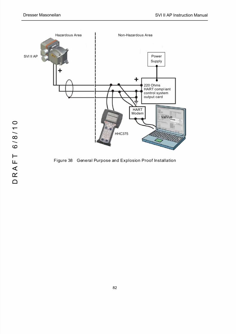
5/8/2018 EW2002 AP 0610 Web_SVI2Ap With Remote Sensor - slidepdf.com
http://slidepdf.com/reader/full/ew2002-ap-0610-websvi2ap-with-remote-sensor 94/160
SVI II AP Instruction Manual
82
D R
A F T
6 / 8 / 1 0
Dresser Masoneilan
Figure 38 General Purpose and Explosion Proof Installation
Hazardous Area Non-Hazardous Area
Power
Supply
220 OhmsHART compliantcontrol systemoutput card
HARTModem
SVI II AP
HHC375
ValVue

5/8/2018 EW2002 AP 0610 Web_SVI2Ap With Remote Sensor - slidepdf.com
http://slidepdf.com/reader/full/ew2002-ap-0610-websvi2ap-with-remote-sensor 95/160
83
SVI II AP Setups Wiring an SVI II AP
Figure 39 Intrinsically Safe Installation
Power
Supply
220 Ohms
HART Compliant
Control System
Output Card
HART
Modem
SVI II AP
HHC375
ValVue
Barrier
Resistance
Single ChannelZener Barrier
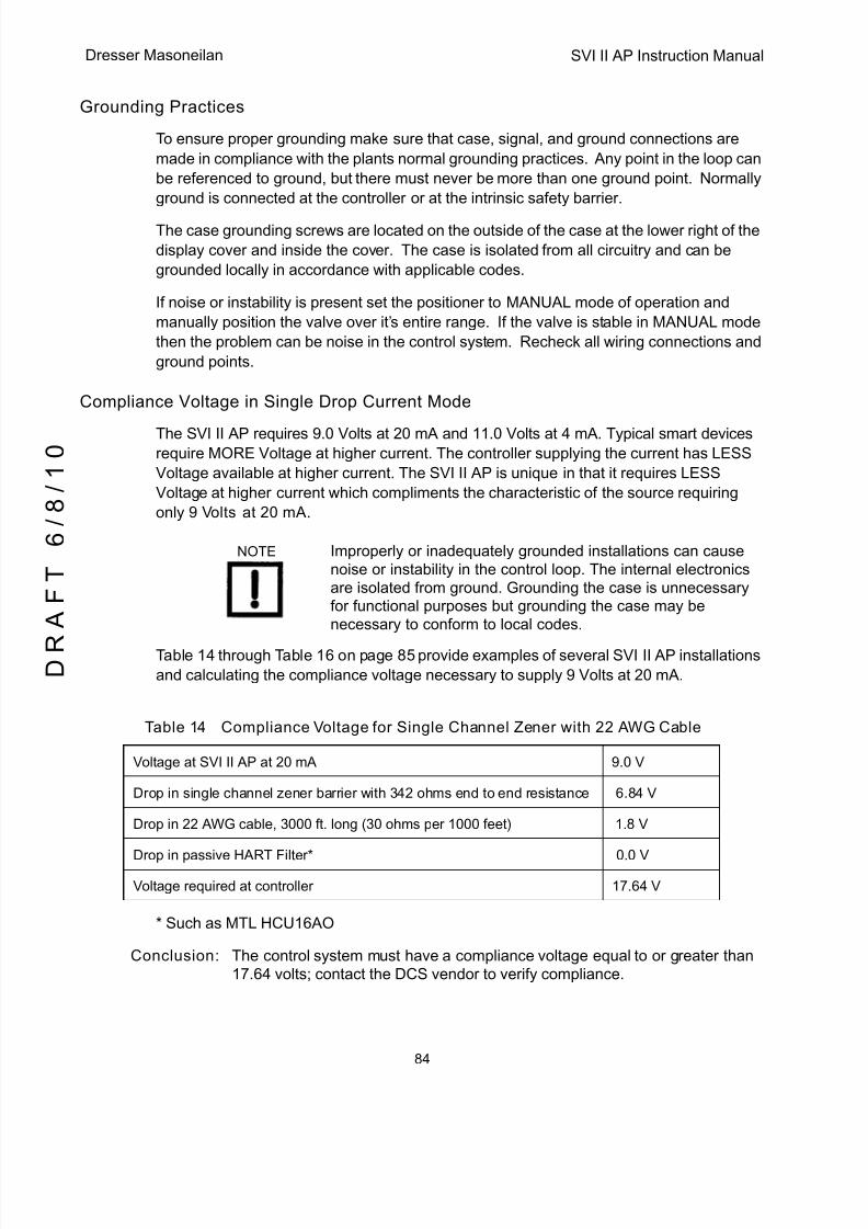
5/8/2018 EW2002 AP 0610 Web_SVI2Ap With Remote Sensor - slidepdf.com
http://slidepdf.com/reader/full/ew2002-ap-0610-websvi2ap-with-remote-sensor 96/160
SVI II AP Instruction Manual
84
D R
A F T
6 / 8 / 1 0
Dresser Masoneilan
Grounding Practices
To ensure proper grounding make sure that case, signal, and ground connections are
made in compliance with the plants normal grounding practices. Any point in the loop can
be referenced to ground, but there must never be more than one ground point. Normally
ground is connected at the controller or at the intrinsic safety barrier.
The case grounding screws are located on the outside of the case at the lower right of the
display cover and inside the cover. The case is isolated from all circuitry and can be
grounded locally in accordance with applicable codes.
If noise or instability is present set the positioner to MANUAL mode of operation and
manually position the valve over it’s entire range. If the valve is stable in MANUAL mode
then the problem can be noise in the control system. Recheck all wiring connections and
ground points.
Compliance Voltage in Single Drop Current Mode
The SVI II AP requires 9.0 Volts at 20 mA and 11.0 Volts at 4 mA. Typical smart devicesrequire MORE Voltage at higher current. The controller supplying the current has LESS
Voltage available at higher current. The SVI II AP is unique in that it requires LESS
Voltage at higher current which compliments the characteristic of the source requiring
only 9 Volts at 20 mA.
NOTE Improperly or inadequately grounded installations can cause noise or instability in the control loop. The internal electronics are isolated from ground. Grounding the case is unnecessary for functional purposes but grounding the case may be necessary to conform to local codes.
Table 14 through Table 16 on page 85 provide examples of several SVI II AP installations
and calculating the compliance voltage necessary to supply 9 Volts at 20 mA.
* Such as MTL HCU16AO
Conclusion: The control system must have a compliance voltage equal to or greater than17.64 volts; contact the DCS vendor to verify compliance.
Table 14 Compliance Voltage for Single Channel Zener with 22 AWG Cable
Voltage at SVI II AP at 20 mA 9.0 V
Drop in single channel zener barrier with 342 ohms end to end resistance 6.84 V
Drop in 22 AWG cable, 3000 ft. long (30 ohms per 1000 feet) 1.8 V
Drop in passive HART Filter* 0.0 V
Voltage required at controller 17.64 V

5/8/2018 EW2002 AP 0610 Web_SVI2Ap With Remote Sensor - slidepdf.com
http://slidepdf.com/reader/full/ew2002-ap-0610-websvi2ap-with-remote-sensor 97/160
85
Wire Size and Conduit Wiring an SVI II AP
* Such as R. Stahl Model 9318/16-22-10. Consult R. Stahl.
Conclusion: The compliance voltage issue is not present because the Isolator provides allthe necessary voltage.
Conclusion: The control system must have a compliance voltage equal to or greater than16.3 volts; contact the DCS vendor to verify compliance.
Wire Size and Conduit
Electrical connections are made to the electronics module terminal board as shown in
Figure 27 on page 41. The terminals accept wire sizes up to AWG 14. The SVI II AP is
supplied with two 1/2" NPT conduit entries. M20 adapters are available. Internal and
external ground terminals are provided for use if grounding is required.
NOTE When an intrinsic safety barrier separates the SVI II AP from
the modem or HHC a HART compliant barrier must be used.See Chapter Six for details.
Table 15 Compliance Voltage for Galvanic Isolator with 22 AWG Cable
Voltage at SVI II AP at 20 mA 9.0 V
Drop in 22 AWG cable, 3000 ft. long (30 ohms per 1000 feet) 1.8 V
Required voltage at Isolator 10.8 V
Voltage available from Isolator rated to drive 22 mA into 700 ohms* 13.2 V
Voltage required at controller Not applicable - Isolator
supplies the power
Table 16 Compliance Voltage for No Barrier with HART Filter and Resistor and 18 AWG
Cable
Voltage at SVI II AP at 20 mA 9.0 V
Drop in 220 Ohm resistor 4.4 V
Drop in 18 AWG cable, 6000 ft. long (12 ohms per 1000 feet) 0.6 V
Drop in passive HART Filter* 2.3 V
Voltage required at controller 16.3 V
5/8/2018 EW2002 AP 0610 Web_SVI2Ap With Remote Sensor - slidepdf.com
http://slidepdf.com/reader/full/ew2002-ap-0610-websvi2ap-with-remote-sensor 98/160
SVI II AP Instruction Manual
86
D R
A F T
6 / 8 / 1 0
Dresser Masoneilan
HART Physical Layer Compliance of the Control System
Communications to a SVI II AP requires a HART-compliant communications loop. The
HART protocol specifies the noise level, impedance requirements, and configuration of
the loop. The controller or output card of the control system must comply with the
Physical Layer Specification.
Impedance Constraints
HART communication is based on the talking device generating an AC current
superimposed on the 4 - 20 mA control signal. Two frequencies are generated; 1200 Hz
representing the digital value 1 and 2200 Hz representing the digital value 0 . The listening
device responds to the voltage generated when the AC current flows through the loop
impedance. In order to generate a voltage from a current there must be impedance.
HART Protocol requires that this impedance be at least 220 Ohms at the tone signaling
frequencies.
HART compliant current sources are supplied with the correct Impedance VersusFrequency Characteristic. In Non-Compliant Current Sources there may be a noise
reduction capacitor across the output that lowers the impedance at higher frequencies
and thus lowers the signaling voltage. To be certain that at least 220 Ohms of impedance
is presented by the current source a resistor can be added in series with the current
source. This reduces the effective compliance voltage of the current source by 20 mA
times the value of the series resistor. An added resistor is unnecessary during tests with
high impedance current calibrators such as the Altek Model 334 Loop Calibrator.
Noise Constraints
HART Communication depends on converting two frequencies (1200 and 2200 Hz) intodigital values 1 and 0 . Noise can cause errors in the conversion. Conventional good
wiring practice, such as use of twisted shielded pair cable with the shield and signal loop
grounded at only one point, minimizes the effects of noise.
5/8/2018 EW2002 AP 0610 Web_SVI2Ap With Remote Sensor - slidepdf.com
http://slidepdf.com/reader/full/ew2002-ap-0610-websvi2ap-with-remote-sensor 99/160
87
Cabling and Interconnection Wiring an SVI II AP
Cabling and Interconnection Requirements
Interconnections are made using shielded twisted pair cables. The shield is connected to
ground at one point only. The signal loop is grounded at only one point in accordance with
plant electrical standards. It is customary to ground the signal at the controller or intrinsic
safety barrier. The SVI II AP is supplied with two 1/2" NPT conduit entries. M20 adapters
are available. Internal and external ground terminals are provided for case groundingrequirements.
WARNING Install the SVI II AP in accordance with local and national code in both general and hazardous area locations.Substitution of components can impair suitability for use in hazardous locations.
NOTE The internal electronic components are isolated for ground.Grounding the case is unnecessary for functional purposes.Grounding the case may be necessary to conform to local
codes.
Capacitance vs. Length of Cable for HART
The HART Communications Foundations specifies cable capacitance requirements to
preserve signal strength. Refer to the standards for detailed calculation methods.
CAUTION Do not connect a HART modem and a PC to a control circuit unless the controller is HART compatible or has a HART filter.Loss of control or a process upset can occur if the controller output circuit is not compatible with HART signals.
HART Filter Required for Certain Control System Output Circuits
The SVI II AP is intended for use with all control systems. However, output circuits of
several major DCS systems are incompatible with the tones used for HART signals. You
must verify that the DCS or controller works reliably with the HART protocol. When the
DCS is incompatible an external HART filter must be installed between the field wiring
and the output card. MTL manufactures the HART filter HCU16AO. It is a 16 channel DIN
rail mounted device composed of passive circuitry that introduces negligible voltage drop.
For additional information, contact MTL.
NOTE A control circuit must be HART compatible or have a HART filter installed. Contact the manufacturer of the controller or DCS. See “HART Filter Requirements” on page 99 . of this manual for more information
5/8/2018 EW2002 AP 0610 Web_SVI2Ap With Remote Sensor - slidepdf.com
http://slidepdf.com/reader/full/ew2002-ap-0610-websvi2ap-with-remote-sensor 100/160
SVI II AP Instruction Manual
88
D R
A F T
6 / 8 / 1 0
Dresser Masoneilan
Split Range Applications
The SVI II AP is designed to operate in split range configurations supporting up to three
control valves connected to a single controller output. Minimum input current span for
each SVI II AP is 5 mA. For each positioner the upper range value is between 8 and 20
mA and the lower range value is between 4 and 14 mA. For example, three devices mightbe configured with input current ranges of 4 - 9 mA; 9 - 14 mA, and 14 - 20 mA. Split
range operation with SVI II AP requires special consideration of the compliance voltage.
The SVI II AP requires at least 9.0 Volts. Two SVI II AP in series requires at least 18.0
Volts in addition to the voltage drops in wiring and other series devices. Typical controller
output current sources rarely deliver 24 Volts, so the system can become voltage starved.
It is possible to boost the compliance voltage of the DCS using a series wired voltage
source power supply, as shown in Figure 43 on page 94. The total loop voltage must not
exceed the rating for the controller output current source. Contact the DCS vendor to
validate this approach.
NOTE The internal electronic components are isolated from ground.Grounding the case is unnecessary for functional purposes.Grounding the case may be necessary to conform to local codes.
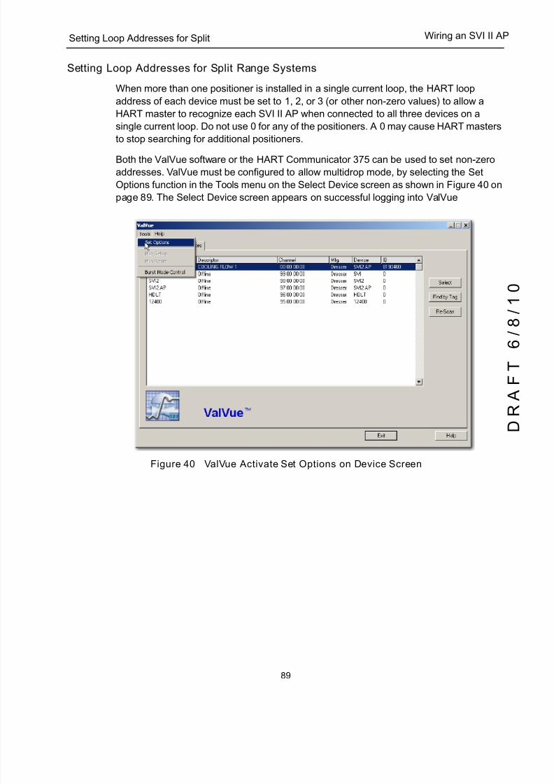
5/8/2018 EW2002 AP 0610 Web_SVI2Ap With Remote Sensor - slidepdf.com
http://slidepdf.com/reader/full/ew2002-ap-0610-websvi2ap-with-remote-sensor 101/160
89
Setting Loop Addresses for Split Wiring an SVI II AP
Setting Loop Addresses for Split Range Systems
When more than one positioner is installed in a single current loop, the HART loop
address of each device must be set to 1, 2, or 3 (or other non-zero values) to allow a
HART master to recognize each SVI II AP when connected to all three devices on a
single current loop. Do not use 0 for any of the positioners. A 0 may cause HART masters
to stop searching for additional positioners.
Both the ValVue software or the HART Communicator 375 can be used to set non-zero
addresses. ValVue must be configured to allow multidrop mode, by selecting the Set
Options function in the Tools menu on the Select Device screen as shown in Figure 40 on
page 89. The Select Device screen appears on successful logging into ValVue
Figure 40 ValVue Activate Set Options on Device Screen

5/8/2018 EW2002 AP 0610 Web_SVI2Ap With Remote Sensor - slidepdf.com
http://slidepdf.com/reader/full/ew2002-ap-0610-websvi2ap-with-remote-sensor 102/160
SVI II AP Instruction Manual
90
D R
A F T
6 / 8 / 1 0
Dresser Masoneilan
Multiple Output Circuit Control System
ValVue supports HART devices including, the SVI II AP with non-zero polling addresses
and supports for multiple SVI II AP on the same loop, for split ranging. To enable this
support, check the Multidrop box as shown in Figure 41. If unchecked, ValVue looks for
devices only at polling address 0. When in multidrop mode, even if a device is found at
polling address 0, other polling addresses are searched.
DCS systems offer multiple independent analog outputs driven by the same control signal
to solve the voltage problem with split ranged positioners. Use of such systems is
recommended for split range applications. The HART address of each SVI II AP are 0 .
Figure 41 ValVue Setup Options for Multi-Drop
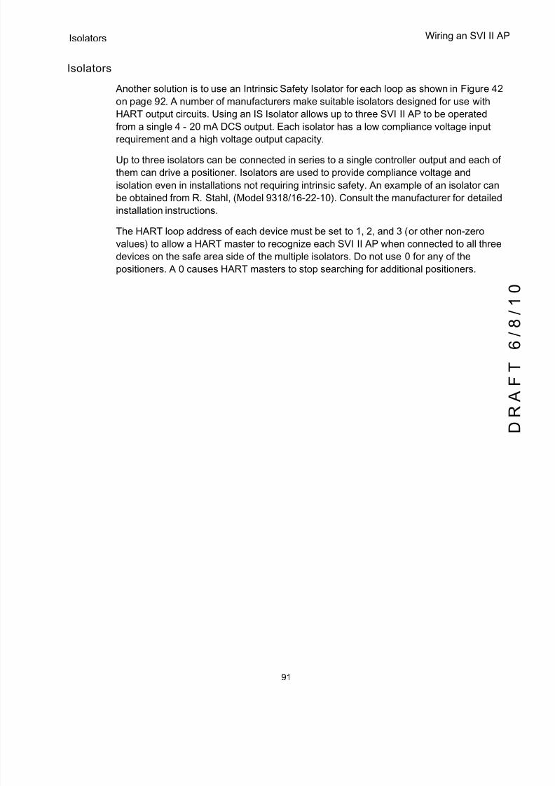
5/8/2018 EW2002 AP 0610 Web_SVI2Ap With Remote Sensor - slidepdf.com
http://slidepdf.com/reader/full/ew2002-ap-0610-websvi2ap-with-remote-sensor 103/160
91
Isolators Wiring an SVI II AP
Isolators
Another solution is to use an Intrinsic Safety Isolator for each loop as shown in Figure 42
on page 92. A number of manufacturers make suitable isolators designed for use with
HART output circuits. Using an IS Isolator allows up to three SVI II AP to be operated
from a single 4 - 20 mA DCS output. Each isolator has a low compliance voltage input
requirement and a high voltage output capacity.
Up to three isolators can be connected in series to a single controller output and each of
them can drive a positioner. Isolators are used to provide compliance voltage and
isolation even in installations not requiring intrinsic safety. An example of an isolator can
be obtained from R. Stahl, (Model 9318/16-22-10). Consult the manufacturer for detailed
installation instructions.
The HART loop address of each device must be set to 1, 2, and 3 (or other non-zero
values) to allow a HART master to recognize each SVI II AP when connected to all three
devices on the safe area side of the multiple isolators. Do not use 0 for any of the
positioners. A 0 causes HART masters to stop searching for additional positioners.
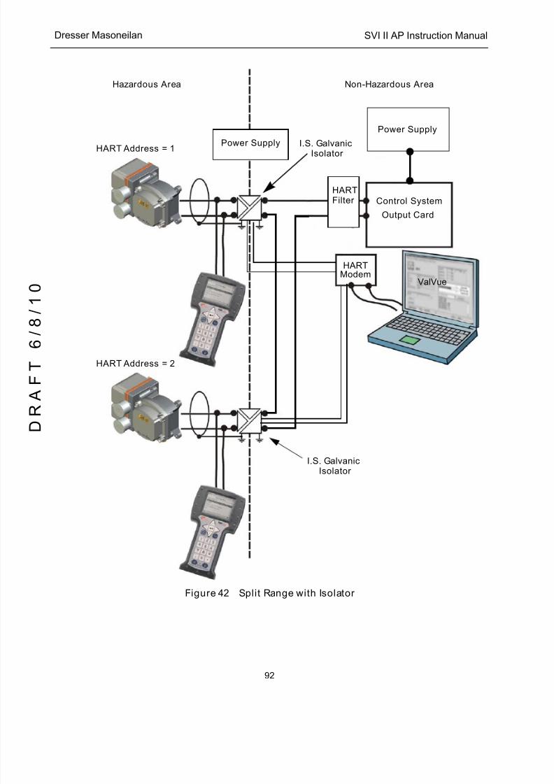
5/8/2018 EW2002 AP 0610 Web_SVI2Ap With Remote Sensor - slidepdf.com
http://slidepdf.com/reader/full/ew2002-ap-0610-websvi2ap-with-remote-sensor 104/160
SVI II AP Instruction Manual
92
D R
A F T
6 / 8 / 1 0
Dresser Masoneilan
Figure 42 Split Range with Isolator
HARTFilter
HART
ModemValVue
Control System
Output Card
Power Supply
Power Supply
Hazardous Area Non-Hazardous Area
HART Address = 1
HART Address = 2
I.S. GalvanicIsolator
I.S. GalvanicIsolator
5/8/2018 EW2002 AP 0610 Web_SVI2Ap With Remote Sensor - slidepdf.com
http://slidepdf.com/reader/full/ew2002-ap-0610-websvi2ap-with-remote-sensor 105/160
93
Supplemental Power Supply Wiring an SVI II AP
Supplemental Power Supply
Another approach is to boost the compliance voltage of the DCS using a supplemental
power supply (see Figure 43 on page 94) with the split ranged SVI II AP positioners
connected in series with the supply. It is not practical to use supplemental supplies when
Intrinsic Safety is required. The barriers do not permit adequate voltage. Contact the DCS
vendor to verify that the output circuit is compatible with the added voltage. Thesupplemental voltage must equal 9.0 volts for each additional SVI II AP. Exceeding the
values in Table 17 will cause damage if the signal wires are short-circuited.
Verify Wiring and Connections
For split range installations there are additional constraints on the split range system: the
minimum span must be 5 mA; the upper range value must be 8 mA to 20 mA; the lower
range values must be 4 mA to 14 mA.
Use the following procedure to ensure that the SVI II AP split range system is properly
powered:
q Connect a DC voltmeter across the input terminals.q For an input current value between 4 and 20 mA the voltage varies between 11 V
and 9 V respective.
q Current is read from the local display or with a milliammeter installed in series the
SVI II AP.
q When voltage exceeds 11 V check that polarity is correct.
q If voltage is less than 9 V and polarity is correct, voltage compliance of current
source is inadequate.
q Connect a milliammeter in series with the current signal. Verify that source can
supply 20 mA to SVI II AP input.
q If 20 mA is not attainable, see troubleshooting.
NOTE Improperly or inadequately grounded installations can cause noise or instability in the control loop. The internal electronic components are isolated from ground. Grounding the case is unnecessary for functional purposes but grounding the case may be necessary to conform to local codes.
Table 17 Supplemental Voltage for Split Range
Number of SVI II APs on a Current Loop Maximum Allowable Supplemental Voltage
1 0
2 9.0 VDC
3 18.0 VDC
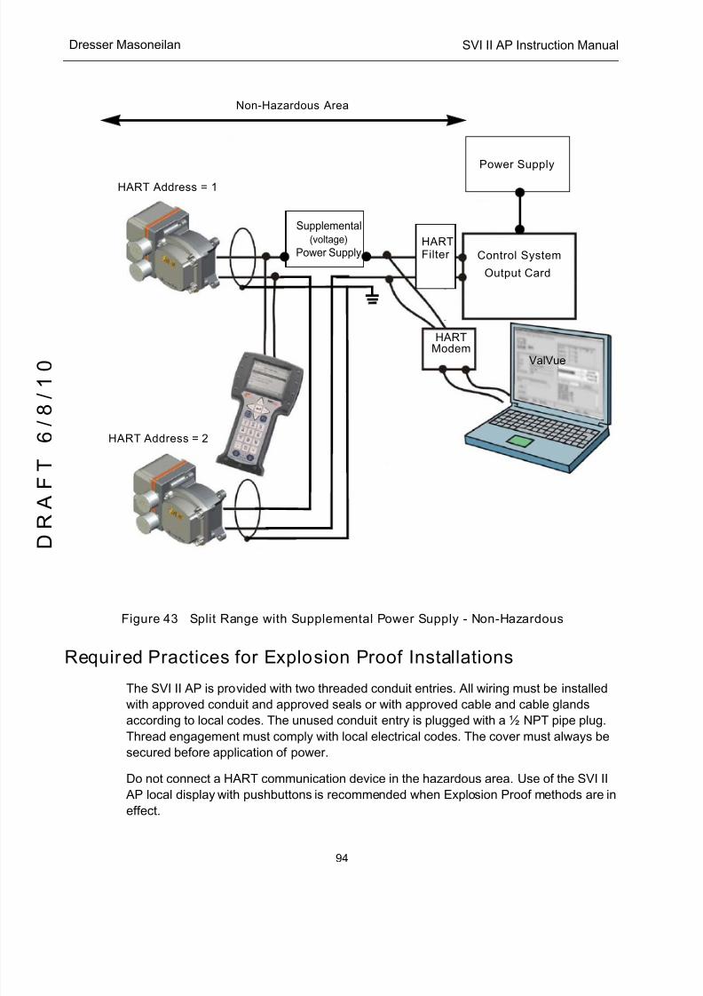
5/8/2018 EW2002 AP 0610 Web_SVI2Ap With Remote Sensor - slidepdf.com
http://slidepdf.com/reader/full/ew2002-ap-0610-websvi2ap-with-remote-sensor 106/160
SVI II AP Instruction Manual
94
D R
A F T
6 / 8 / 1 0
Dresser Masoneilan
Figure 43 Split Range with Supplemental Power Supply - Non-Hazardous
Required Practices for Explosion Proof Installations
The SVI II AP is provided with two threaded conduit entries. All wiring must be installed
with approved conduit and approved seals or with approved cable and cable glands
according to local codes. The unused conduit entry is plugged with a ½ NPT pipe plug.
Thread engagement must comply with local electrical codes. The cover must always be
secured before application of power.
Do not connect a HART communication device in the hazardous area. Use of the SVI II
AP local display with pushbuttons is recommended when Explosion Proof methods are in
effect.
HARTFilter
HART
ModemValVue
Control System
Output Card
Power Supply
HART Address = 1
HART Address = 2
Power Supply
Supplemental(voltage)
Non-Hazardous Area

5/8/2018 EW2002 AP 0610 Web_SVI2Ap With Remote Sensor - slidepdf.com
http://slidepdf.com/reader/full/ew2002-ap-0610-websvi2ap-with-remote-sensor 107/160
95
Clarification of Terminology Wiring an SVI II AP
Clarification of Terminology
In Factory Mutual Research and Canadian Standards Association codes, Explosion Proof
means use of approved enclosures and conduit enclosed cables, but in ATEX countries,
this method is called Flameproof . In ATEX countries, Explosion Proof means both
Flameproof and Intrinsically Safe.
Recommended Practice for Severe or Humid Environments
The circuitry of SVI II AP is encapsulated for protection from corrosive atmospheres. To
prevent moisture from damaging the electronics of the SVI II AP use a sealed junction
box in high humidity or tropical environments. The wiring from the junction box to the SVI
II AP is sealed by flexible cable with a cable gland or with a potted nipple and pigtail,
where applicable codes permit.

5/8/2018 EW2002 AP 0610 Web_SVI2Ap With Remote Sensor - slidepdf.com
http://slidepdf.com/reader/full/ew2002-ap-0610-websvi2ap-with-remote-sensor 108/160
SVI II AP Instruction Manual
This page intentionally left blank.
D R
A F T
6 / 8 / 1 0
5/8/2018 EW2002 AP 0610 Web_SVI2Ap With Remote Sensor - slidepdf.com
http://slidepdf.com/reader/full/ew2002-ap-0610-websvi2ap-with-remote-sensor 109/160
97
7HART Communicationswith Intrinsic Safety
Overview
When an SVI II AP is installed in a hazardous area in accordance with the applicable codes
and standards for Intrinsic Safety there are wiring considerations for successful operation inaddition to the requirements for safety. The choice and application of intrinsic safety barriers
requires special training. For additional information, consult MTL Instruments PLC
Measurement Technology Limited: www.mtl-inst.com or R.Stahl, Inc. www.rstahl.com.
All installations must comply with plant standards and local and international electrical codes.
There are three basic barrier types:
q Single channel zener diode barriers
q Dual channel zener diode barriers
qActive galvanic isolators
To determine if the installation will perform successfully with HART communications you must
consider HART filter requirements and HART barrier compliance.

5/8/2018 EW2002 AP 0610 Web_SVI2Ap With Remote Sensor - slidepdf.com
http://slidepdf.com/reader/full/ew2002-ap-0610-websvi2ap-with-remote-sensor 110/160
SVI II AP Instruction Manual
98
D R
A F T
6 / 8 / 1 0
Dresser Masoneilan
HART Barrier Compliance
The intrinsic safety barrier must be designed to transmit the HART signals in both
directions. Both passive zener diode barriers and active galvanic isolators are offered with
HART compliance. Consult the manufacturer or refer to the documents listed at the end of
this instruction manual.
Figure 44 Intrinsically Safe Installation with Zener Barrier and HART Filter
Power
Supply
HART Compliant
Control System
Output Card
HARTModem
SVI II AP
HHC375
ValVue
Barrier
Resistance
Single Channel
Zener Barrier
Hazardous AreaNon-hazardous Area
HART
Filter
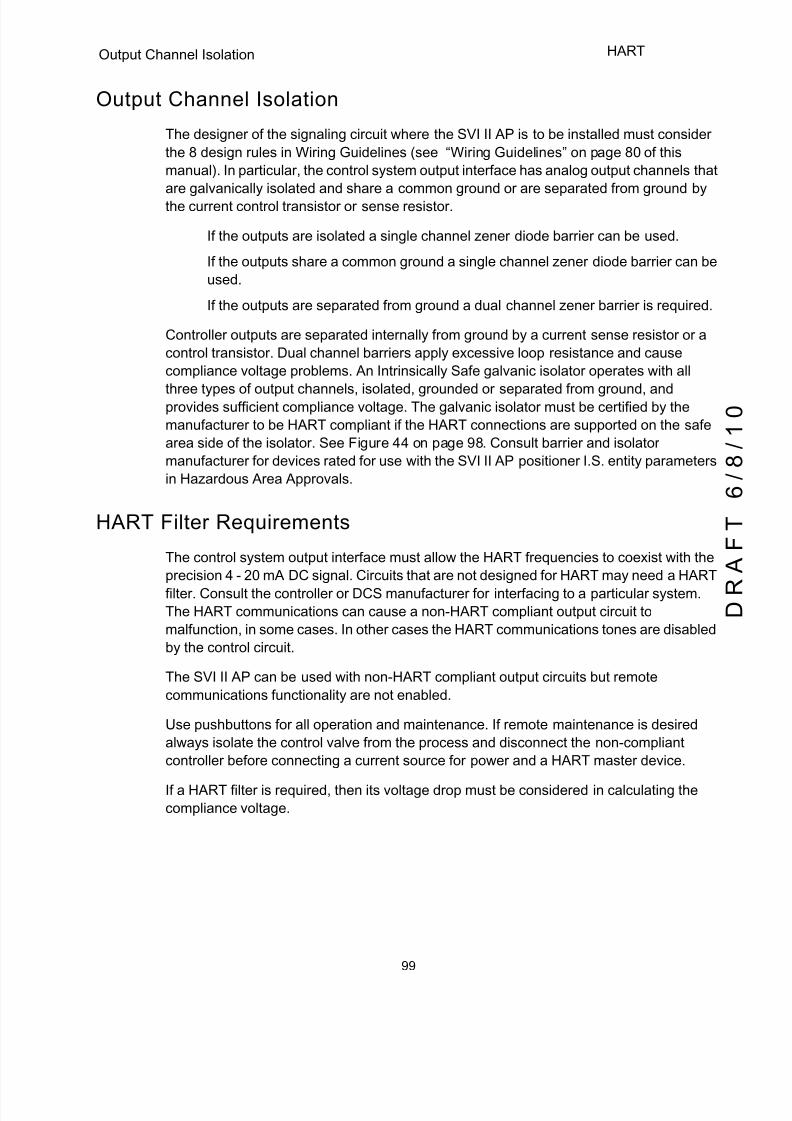
5/8/2018 EW2002 AP 0610 Web_SVI2Ap With Remote Sensor - slidepdf.com
http://slidepdf.com/reader/full/ew2002-ap-0610-websvi2ap-with-remote-sensor 111/160
99
Output Channel Isolation HART
Output Channel Isolation
The designer of the signaling circuit where the SVI II AP is to be installed must consider
the 8 design rules in Wiring Guidelines (see “Wiring Guidelines” on page 80 of this
manual). In particular, the control system output interface has analog output channels that
are galvanically isolated and share a common ground or are separated from ground bythe current control transistor or sense resistor.
q If the outputs are isolated a single channel zener diode barrier can be used.
q If the outputs share a common ground a single channel zener diode barrier can be
used.
q If the outputs are separated from ground a dual channel zener barrier is required.
Controller outputs are separated internally from ground by a current sense resistor or a
control transistor. Dual channel barriers apply excessive loop resistance and cause
compliance voltage problems. An Intrinsically Safe galvanic isolator operates with all
three types of output channels, isolated, grounded or separated from ground, andprovides sufficient compliance voltage. The galvanic isolator must be certified by the
manufacturer to be HART compliant if the HART connections are supported on the safe
area side of the isolator. See Figure 44 on page 98. Consult barrier and isolator
manufacturer for devices rated for use with the SVI II AP positioner I.S. entity parameters
in Hazardous Area Approvals.
HART Filter Requirements
The control system output interface must allow the HART frequencies to coexist with the
precision 4 - 20 mA DC signal. Circuits that are not designed for HART may need a HART
filter. Consult the controller or DCS manufacturer for interfacing to a particular system.
The HART communications can cause a non-HART compliant output circuit to
malfunction, in some cases. In other cases the HART communications tones are disabled
by the control circuit.
The SVI II AP can be used with non-HART compliant output circuits but remote
communications functionality are not enabled.
Use pushbuttons for all operation and maintenance. If remote maintenance is desired
always isolate the control valve from the process and disconnect the non-compliant
controller before connecting a current source for power and a HART master device.
If a HART filter is required, then its voltage drop must be considered in calculating the
compliance voltage.
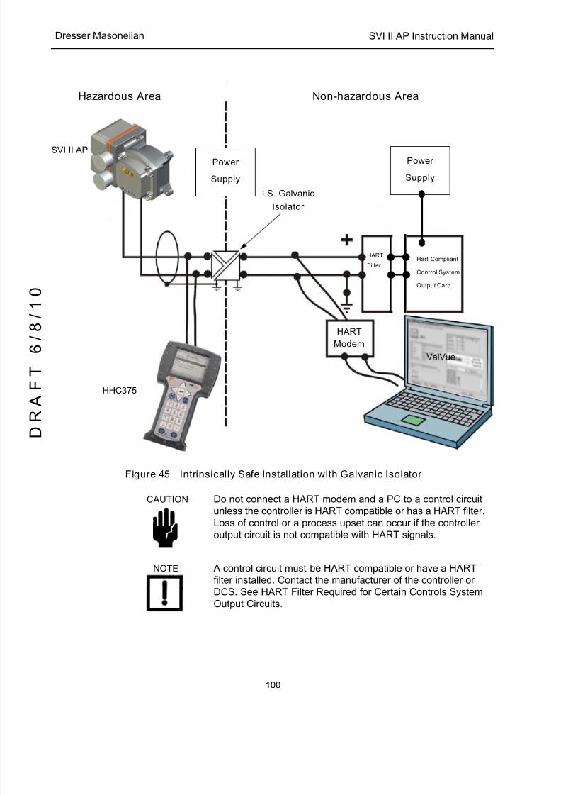
5/8/2018 EW2002 AP 0610 Web_SVI2Ap With Remote Sensor - slidepdf.com
http://slidepdf.com/reader/full/ew2002-ap-0610-websvi2ap-with-remote-sensor 112/160
SVI II AP Instruction Manual
100
D R
A F T
6 / 8 / 1 0
Dresser Masoneilan
Figure 45 Intrinsically Safe Installation with Galvanic Isolator
CAUTION Do not connect a HART modem and a PC to a control circuit unless the controller is HART compatible or has a HART filter.Loss of control or a process upset can occur if the controller output circuit is not compatible with HART signals.
NOTE A control circuit must be HART compatible or have a HART filter installed. Contact the manufacturer of the controller or DCS. See HART Filter Required for Certain Controls System Output Circuits.
Power
Supply
Hart Compliant
Control System
Output Card
HART
Modem
SVI II AP
HHC375
ValVue
I.S. Galvanic
Isolator
Hazardous Area Non-hazardous Area
HART
Filter
Power
Supply

5/8/2018 EW2002 AP 0610 Web_SVI2Ap With Remote Sensor - slidepdf.com
http://slidepdf.com/reader/full/ew2002-ap-0610-websvi2ap-with-remote-sensor 113/160
101
Modem and Computer Use in HART
Modem and Computer Use in Intrinsically Safe Circuits
Many HART modems that are in use today are not approved for connections to
Intrinsically Safe control circuits. Most portable computers are NOT approved for use in
hazardous areas. Modems can be safely connected to the safe area side of barriers, and
isolators. Observe requirements for the HART filter.
MACTek Intrinsically Safe modem, Model 010005
The VIATOR RS232 HART Interface [Eex ia] IIC complies with the Essential Health and
Safety Requirements relating to the design and construction of equipment and protective
systems intended for use in potentially explosive atmospheres. Requirements given in
Annex II of the Directive 94/9/EC (ATEX Directive) of the European Parliament and the
Council of 23 March 1994. Consult MACTek Corporation, http://www.mactekcorp.com/
company.html for detailed requirements for safe use.
MACTek Warning
"This product has not been tested by any certification agency such as Factory Mutual with
jurisdiction outside the European Union for intrinsic safety. The product can be used
outside the European Union (e.g. in the USA) on the sole authority of the buyer. MACTek
makes no claims of suitability and offers no warranties regarding the use of this product
for connection of PCs to circuits extending into hazardous areas in countries outside the
European Union."
Do not connect a PC or HART modem to an intrinsically safe circuit except on the safe
area side of a barrier. Do not operate a PC in a hazardous area without compliance with
local and plant regulations.
Use of Handheld Communicators In Intrinsically Safe Circuits
WARNING The HC375 is not approved for use in hazardous areas that use explosion proof safety practices. Do not use the HC375 unless the area has been declared safe (Hot Work Permit).
The HART Communicator HC375 is approved to communicate with intrinsically safe control circuits in hazardous areas. Read the product Manual for the HART Communicator. Observe all warnings. The intrinsic safety entity parameters must be added to the SVI II AP entity
parameters to determine suitability for use in any intrinsically safe circuit. Observe the labels on the HC375 or consult the manufacturer.

5/8/2018 EW2002 AP 0610 Web_SVI2Ap With Remote Sensor - slidepdf.com
http://slidepdf.com/reader/full/ew2002-ap-0610-websvi2ap-with-remote-sensor 114/160
SVI II AP Instruction Manual
This page intentionally left blank.
D R
A F T
6 / 8 / 1 0
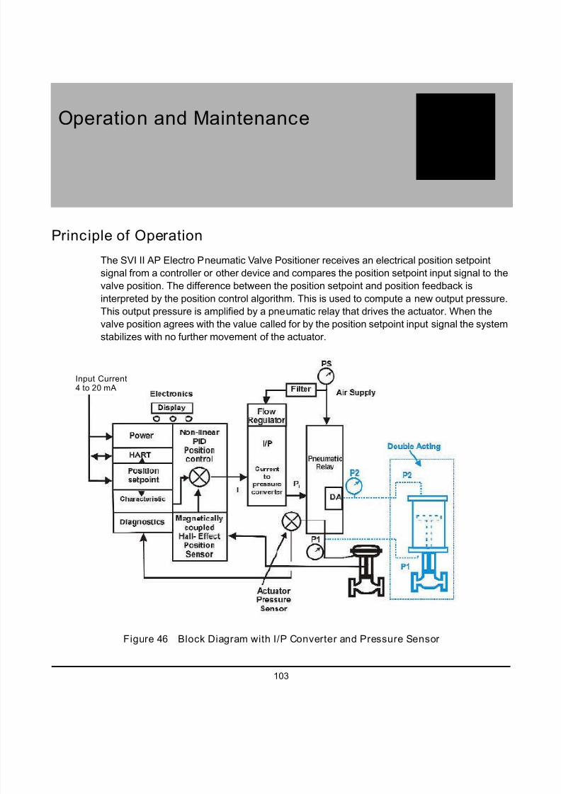
5/8/2018 EW2002 AP 0610 Web_SVI2Ap With Remote Sensor - slidepdf.com
http://slidepdf.com/reader/full/ew2002-ap-0610-websvi2ap-with-remote-sensor 115/160
103
8Operation and Maintenance
Principle of Operation
The SVI II AP Electro Pneumatic Valve Positioner receives an electrical position setpoint
signal from a controller or other device and compares the position setpoint input signal to thevalve position. The difference between the position setpoint and position feedback is
interpreted by the position control algorithm. This is used to compute a new output pressure.
This output pressure is amplified by a pneumatic relay that drives the actuator. When the
valve position agrees with the value called for by the position setpoint input signal the system
stabilizes with no further movement of the actuator.
Figure 46 Block Diagram with I/P Converter and Pressure Sensor
Input Current4 to 20 mA
5/8/2018 EW2002 AP 0610 Web_SVI2Ap With Remote Sensor - slidepdf.com
http://slidepdf.com/reader/full/ew2002-ap-0610-websvi2ap-with-remote-sensor 116/160
SVI II AP Instruction Manual
104
D R
A F T
6 / 8 / 1 0
Dresser Masoneilan
Physical and Operational Description
The SVI II AP is housed in an industrial, tough, weatherproof, corrosion resistant
aluminum housing that has been designed for operation in hazardous areas as listed in
Appendix B. Electrical connections are made through two 1/2" NPT conduit entries.
Pneumatic connections are made through two or three ¼" NPT ports.
Electronics Module
The Electronics module consists of an electronic circuit encapsulated in a housing. The
electronics include a multiplexer, A/D, D/A, temperature sensor, Hall-Effect magnetic
position sensor, pressure sensors, a micro controller, and a power management/
distribution circuit. The programs controlling the SVI II AP positioner are stored in a flash
memory that allows for the downloading of upgraded firmware.
A separate non-volatile memory stores configuration information, and continuous
diagnostic results. Expansion capabilities include connectors for the addition of the
optional local display with pushbuttons. Using the internal programmed positioneralgorithm, the CPU computes the required output based on information received from the
measurement sensors. The base module has no user repairable components.
Magnetic Position Sensor
A non-contact sensor uses a magnetic field to transfer the position through the wall of the
housing, without penetration, to sense the valve position. A Hall effect device, sealed
within the electronics housing, senses the rotation of a magnetic assembly mounted on
the end of a rotary valve shaft or on a driven linkage mounted on a reciprocating valve.
The output of the Hall sensor provides the position feedback signal to the position control
algorithm. The magnetic assembly is environmentally sealed and is entirely external to
the electronics housing. (See Figure 8 on page 18.) The Hall effect sensor has a
maximum travel range of up to 140° rotation.
Position Retransmit
The position sensor also provides, through the electronics module, readout of valve
position on the optional display and communication of valve position via HART protocol.
The position transmission option provides a 4 - 20 mA signal proportional to valve
position transmitted on a separate pair of leads. A pair of contacts can signal high and low
position limits.
Pressure Sensor
The pressure sensor located in the Electronics Module measures the output of the single
acting relay. The pressure measurement is displayed on the local display or read by a
HART communication device.
5/8/2018 EW2002 AP 0610 Web_SVI2Ap With Remote Sensor - slidepdf.com
http://slidepdf.com/reader/full/ew2002-ap-0610-websvi2ap-with-remote-sensor 117/160
105
Output Switches Operation and Maintenance
Temperature Sensor
A temperature sensor is located in the electronics module and measures ambient
temperature. This measurement is used to provide temperature compensation for the
position and pressure sensors and other internal electronic components. The
temperature is read via the HART communication link to provide a warning of excessive
ambient temperature at the positioner.
Output Switches
The SVI II AP supports two identical contact outputs, SW #1 and SW #2 (Digital Output
switches), that can be logically linked to status bits. The Digital Output switch terminals
are solid state contacts, similar to relay contacts. Each switch requires its own power
source and must be connected to the appropriate connector on the Electronics Module
Terminal Board.
The switches are polarity sensitive and must be connected only to a DC circuit. When
the switch is OPEN the + terminal must be electrically positive with respect to the –
terminal. If the + terminal is electrically negative with respect to the – terminal, then the
switch will conduct. Polarity reversal will not damage the switch, but the switch will
appear to be always ON.
There must be a series load in the circuit to prevent damage to the switch. If the switch
is connected directly across the power source the current will be limited only by
the capacity of the power source and the switch will be damaged.
NOTE A 1 Amp 24 Volt power source delivers much more than 1Amp short circuit current.
The switch is rated for 30 Volts open and 1 Amp closed with a resistive load. An
incandescent load (such as a lamp) draws a surge current of as much as 20 times the
rated current of the lamp as the filament heats up. The switch current capacity is
adequate to drive typical incandescent loads (such as annunciator panel lamps) but a 25
Watt lamp may damage the switch. An inductive load such as a solenoid valve or relay
discharges the energy stored in the coil when it is on into the switch when the coil is
turned off. The switch has adequate capacity to absorb the energy from a typical low
power air solenoid or control relay. Using the switch to operate a large capacity motor
controller may damage the switch. With an incandescent or inductive load, limiting
the rated load current to 0.1 mA is always safe.
5/8/2018 EW2002 AP 0610 Web_SVI2Ap With Remote Sensor - slidepdf.com
http://slidepdf.com/reader/full/ew2002-ap-0610-websvi2ap-with-remote-sensor 118/160
SVI II AP Instruction Manual
106
D R
A F T
6 / 8 / 1 0
Dresser Masoneilan
Switch Settings
The two digital output switches can be opened or closed in response to conditions that
the SVI II AP detects. These conditions are:
0. Always Normal Position - the switch is not controlled by the SVI
II AP and remains in it’s default position1. Failsafe - the switch is activated when the SVI II AP is in failsafe
mode
2. Reset - the switch is activated whenever a reset has occurred
and the switch remains activated until the SVI II AP status is
cleared
3. Position Error - the switch is activated whenever a position error
has occurred and is deactivated when the position recovers to the
correct position
4. Tight Shutoff Active - the switch is activated whenever thedevice is in tight shutoff (tight shutoff is on and the valve position
is less than the tight shutoff position)
5. Position Low Limit - the switch is activated whenever the valve
position is less than the position setting of this switch control
6. Position Upper Limit - the switch is activated whenever the
valve position is greater than the position setting of this switch
control
7. Manual Mode - the switch is activated whenever the SVI II AP is
in manual mode, configure mode, calibrate mode, or diagnostic
mode.
NOTE The contacts are OPEN when the SVI II AP is unpowered and may be made to be open or closed when the flag is asserted after boot.
Pneumatic Module
The pneumatic module consists of an I/P and Relay assembly.
Current-to-Pressure Converter, I/P
The I/P converts a current signal to a pressure signal in the following manner. A fixed coil
creates a magnetic field proportional to the applied current. The field magnetically pulls a
flexure towards a nozzle to increase pressure on the flexure. The pressure on the flexure
increases in response to an increase in the coil current. Encapsulation of the coil provides
protection from the environment.

5/8/2018 EW2002 AP 0610 Web_SVI2Ap With Remote Sensor - slidepdf.com
http://slidepdf.com/reader/full/ew2002-ap-0610-websvi2ap-with-remote-sensor 119/160
107
Pneumatic Module Operation and Maintenance
Single Acting Pneumatic Relay
The single acting pneumatic relay amplifies the pressure from the I/P and increases
airflow as required for stable, responsive, actuator performance. The single acting relay
operates on any supply pressure that is at least 5 psi (.345 bar, 34.5 kPa) above the
required actuator pressure, up to 100 psi (6.9 bar, 690 kPa).
Figure 47 Pneumatic Module with Single Acting Relay
Vent
Relay
I/P Current to Pneumatic Converter
(Pneumatic Amplifier)

5/8/2018 EW2002 AP 0610 Web_SVI2Ap With Remote Sensor - slidepdf.com
http://slidepdf.com/reader/full/ew2002-ap-0610-websvi2ap-with-remote-sensor 120/160
SVI II AP Instruction Manual
108
D R
A F T
6 / 8 / 1 0
Dresser Masoneilan
Double Acting Pneumatic Relay
The double acting pneumatic relay amplifies the pressure from the I/P and provides a pair
of high flow output signals for operating a double acting cylinder actuator. The double
acting relay operates on any supply pressure that is at least 5 psi (.345 bar, 34.5 kPa)
above the required actuator pressure, up to 150 psi (10.35 bar, 1035 kPa). The two output
pressures may be balanced by means of an adjustable seat assembly. The average ofthe two pressures is adjusted to equal 70% of the supply pressure. The double acting
relay is rated for supply pressure to 150 psi (10.35 bar, 1035 kPa).
Figure 48 Double Acting Pneumatic Relay
I/P Current to Pneumatic Converter
Double Acting
Vent
Output 2 Gauge
Output 1 Gauge
Output 1 "Act 1"
Output 2 " Act 2"
Supply Inlet
Supply Gauge
Relay
5/8/2018 EW2002 AP 0610 Web_SVI2Ap With Remote Sensor - slidepdf.com
http://slidepdf.com/reader/full/ew2002-ap-0610-websvi2ap-with-remote-sensor 121/160
109
Optional Display and Pushbuttons Operation and Maintenance
Double Acting Supply Pressure Balance
After installation on the actuator, set supply pressure in accordance with actuator
specifications. Do not exceed the maximum pressure rating of the actuator. The double
acting relay is adjusted at the factory and set to 70% of supply pressure. If adjustment is
required consult the factory.
Optional Display and Pushbuttons
The optional display and buttons are mounted on the SVI II AP cover plate. The three
pushbutton switches operating in conjunction with the display permit reading and
modification of the instrument operating parameters without a PC or HART hand-held
communicator. These switches perform generic functions - Increase, Decrease, and
Accept by movement through a conventional menu structure, see “Using the Digital
Interfaces” on page 45. The switches are operated in a hazardous environment without
compromising the flameproof enclosure.
SVI II AP Maintenance and Repair
The SVI II AP was designed based on a modular concept. All components are
interchangeable allowing for easy, quick component swapping.
The only maintenance procedures recommended for the SVI II AP are:
q Remove and install the cover, for upgrade to display
q Remove and install the I ⁄ P module
q Remove and install the Pneumatic Relay
WARNING Do not remove the instrument cover or connect to an electrical circuit in a Hazardous Area unless the power is disconnected.
Repair
Replacement of the Pneumatic Relay, I/P and cover (with or without display) are the only
field repairs permitted.
Only qualified service personnel are permitted to make repairs.
Only parts supplied by Masoneilan are permitted. This includes not only the major
assemblies but also mounting screws and O-rings. No substitutions with non-Masoneilan
parts are permitted.
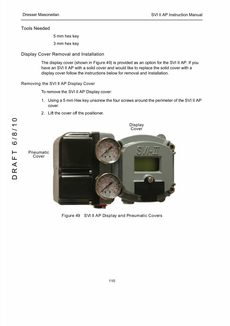
5/8/2018 EW2002 AP 0610 Web_SVI2Ap With Remote Sensor - slidepdf.com
http://slidepdf.com/reader/full/ew2002-ap-0610-websvi2ap-with-remote-sensor 122/160
SVI II AP Instruction Manual
110
D R
A F T
6 / 8 / 1 0
Dresser Masoneilan
Tools Needed
q 5 mm hex key
q 3 mm hex key
Display Cover Removal and Installation
The display cover (shown in Figure 49) is provided as an option for the SVI II AP. If you
have an SVI II AP with a solid cover and would like to replace the solid cover with a
display cover follow the instructions below for removal and installation.
Removing the SVI II AP Display Cover
To remove the SVI II AP Display cover:
1. Using a 5 mm Hex key unscrew the four screws around the perimeter of the SVI II AP
cover.
2. Lift the cover off the positioner.
Figure 49 SVI II AP Display and Pneumatic Covers
CoverDisplay
CoverPneumatic
5/8/2018 EW2002 AP 0610 Web_SVI2Ap With Remote Sensor - slidepdf.com
http://slidepdf.com/reader/full/ew2002-ap-0610-websvi2ap-with-remote-sensor 123/160
111
Display Cover Removal and Operation and Maintenance
Installing the SVI II AP Display Cover
NOTE After replacing the SVI II AP Display Cover you must power up the unit (see “Powering Up the SVI II AP” on page 42 of this guide).
The replacement Display Cover is shipped with a lanyard to prevent the cable (that
connects from the display to the Terminal Board) from breaking. The lanyard must be
inserted under the screw in the lower left corner, that attaches the terminal board to the
SVI II AP housing.
To Install the cover:
1. Install the lanyard and tighten the screw to 5 in-lbs (.565 N-m).
2. Using the 3mm hex key, remove the screw from the lower left corner, connecting the
terminal board to the SVI II AP housing.
3. Connect the cable from the display into the LCD connector on the terminal board.
4. Ensure that the gasket is in its groove in the housing.
5. Place the cover over the screw mounts.
6. Tighten the four screws with the 5 mm hex key.
7. After installing the new display power up the unit (refer to “Powering Up the SVI II AP”
on page 42).
NOTE The cover of the SVI II AP is a critical component for safety in Hazardous Areas. To ensure safe operation the flat surfaces
of the cover and the housing must be clean and absolutely free of particles or dents. There must be no gap between the housing and cover; torque spec is 50 in-lbs (5.65 N-m).
Make sure that:
q The gasket is seated in the groove in the housing flange.
q No wires or retaining cable can be trapped under the cover flange.
q The flange area is not corroded and the surface is not scarred.
q The four cover bolts are securely tightened to 50 in-lbs (5.65 N-m).
5/8/2018 EW2002 AP 0610 Web_SVI2Ap With Remote Sensor - slidepdf.com
http://slidepdf.com/reader/full/ew2002-ap-0610-websvi2ap-with-remote-sensor 124/160
SVI II AP Instruction Manual
112
D R
A F T
6 / 8 / 1 0
Dresser Masoneilan
I ⁄ P Module Removal and Installation
Prior to removing the pneumatic components it is necessary to remove the electronics
module cover (see “Removing the SVI II AP Display Cover” on page 110) and the
pneumatic cover first.
Do not remove the I/P module in a hazardous area unless the power is disconnected.
Application of more than 1.6 mA to the I/P motor can permanently damage it.
The I/P is rigidly assembled to a wire way sleeve that is a critical component for explosion
proof service. Use care to slide the sleeve from the pneumatic module without applying a
strain to it.
Pneumatic Cover Removal
To remove the pneumatic cover:
1. Using a 3 mm hex key, remove the six screws from around the perimeter of the cover
2. Lift the cover off and put aside for installation.
I/P Module Removal
To remove I ⁄ P module:
1. Disconnect the I/P wire from the terminal board.
2. Using a 3 mm hex key, remove the four screws from around the perimeter of the I ⁄ P
module.
3. Lift the module off the positioner.
I/P Module Installation
To install I ⁄ P module:
1. Place the module in the designated area on the positioner.
2. Using a 3 mm hex key, install the four screws around the perimeter of the I ⁄ P module.
3. Replace the I/P wire connector on the terminal board.
4. Replace the Display Cover (see “Installing the SVI II AP Display Cover” on page 111).
Make sure that:
1. The wire is not damaged when feeding it through the housing.
2. A single O-ring is in place on the wire-sleeve and is not damaged.
3. The four retaining screws are tight and torque to 15 in-lb (1.7 N-m).
4. Inserting the wire sleeve through the housing does not require force.

5/8/2018 EW2002 AP 0610 Web_SVI2Ap With Remote Sensor - slidepdf.com
http://slidepdf.com/reader/full/ew2002-ap-0610-websvi2ap-with-remote-sensor 125/160
113
Relay Removal and Installation Operation and Maintenance
Pneumatic Cover Installation
To install the pneumatic cover:
1. Place the cover over the pneumatic module.
2. Using a 3 mm hex key, install the six screws around the perimeter of the cover and
torque to 8 in-lb (.9 N-m).
Relay Removal and Installation
To remove the pneumatic relay:
1. Using a 3 mm hex key, remove the three screws from around the perimeter of the
relay.
2. Lift the relay off the positioner.
Relay Installation
To install pneumatic relay:
1. Place the relay in the designated area on the positioner.
2. Using a 3 mm hex key, install the three screws around the perimeter of the relay.
Make sure that:
1. The five O-rings are seated in the base of the relay and are not damaged.
2. The three mounting screws are tight and torque to 15 in-lb (1.7 N-m).
NOTE When you have completed maintenance on the pneumatic relay it is necessary to reinstall the pneumatic cover. Refer to on “Pneumatic Cover Installation” on page 113 .
Adjusting I/P Zero
The I/P Zero is calibrated at the factory prior to shipment. If there is a problem with I/P
zero please contact your Masoneilan representative.
Connecting Components to the Electronics Module
If it is necessary to remove and install any SVI II AP component you may need toreconnect the component to the SVI II AP Electronics Module via the SVI II AP Terminal
Board. Refer to “Making Connections to the Terminal Board” on page 41 of this manual
for instructions.

5/8/2018 EW2002 AP 0610 Web_SVI2Ap With Remote Sensor - slidepdf.com
http://slidepdf.com/reader/full/ew2002-ap-0610-websvi2ap-with-remote-sensor 126/160
SVI II AP Instruction Manual
114
D R
A F T
6 / 8 / 1 0
Dresser Masoneilan
Repair by Replacement
Using ValVue and repair-by-replacement is the fastest method to service an SVI II AP.
See the ValVue instruction manual for details regarding uploading and downloading
configuration files. Upload all configuration information from the installed positioner to
ValVue, then install the replacement positioner and download the configuration file intothe replacement unit. Run STOPS, and autoTUNE, and the repair is complete. The
positioner that was removed can be refurbished and reused.
NOTE Substitution of components can void safety approvals
Internal Diagnostics
The SVI II AP performs internal self-diagnostics and hardware checks. When ValVue orHART Handheld or the local display indicates that there are error messages write them
down for troubleshooting.
FAILSAFE Mode
Several of the internal diagnostics tests puts the SVI II AP into FAILSAFE mode if the
errors continue for a preset time. When the SVI II AP goes into FAILSAFE, the valve is
driven to its Failsafe position. It remains in that position until a technician clears the cause
of the error and resets the instrument. Reset is performed in two ways:
qConnect a HART modem and ValVue, and then click on the RESET button.
or
q Turn the power off and on.
To prevent the valve from moving after reset, put the controller in manual, and set the
valve position setpoint to the failsafe position 0% if ATO, 100% if ATC. You can set a
special case of FAILSAFE. You can set a Position Error Band and a Position Error Time 2
that forces the valve to its failsafe position if the position error exceeds the band for a time
longer than time 2. This can be used on critical loops to force the process to trip if the
positioner is unable to control the valve.
Upgrading Firmware
The SVI II AP is equipped with a nonvolatile re-writable Flash Memory for program
storage. The firmware can be updated as improvements and advances are made in the
embedded programs that operate the SVI II AP. Firmware improvements for the SVI II AP
can be obtained by contacting the factory.
5/8/2018 EW2002 AP 0610 Web_SVI2Ap With Remote Sensor - slidepdf.com
http://slidepdf.com/reader/full/ew2002-ap-0610-websvi2ap-with-remote-sensor 127/160
115
Tools Required Operation and Maintenance
Tools Required
q HART modem
q IBM PC with Windows 2000, XP or later, 16 MB RAM
q ValVue (provided with software upgrade on CD-ROM)
Installing Firmware Upgrade
It is recommended that the configuration is uploaded and saved prior to the installation
procedure. Follow the ValVue instructions to save the old configuration. Follow the
detailed instructions included with the software update.
To check the firmware version cycle the power off, then on, to perform a cold start. The
display shows software version in upper right corner. When maintenance is complete
reinstall the positioner and perform the checkout procedure detailed in “Installation and
Set Up” on page 7. Consult the factory for firmware upgrade services. ValVue is the
recommended tool for complete re-configuration. See “Configuration and Calibration” on
page 65.

5/8/2018 EW2002 AP 0610 Web_SVI2Ap With Remote Sensor - slidepdf.com
http://slidepdf.com/reader/full/ew2002-ap-0610-websvi2ap-with-remote-sensor 128/160
SVI II AP Instruction Manual
This page intentionally left blank.
D R
A F T
6 / 8 / 1 0
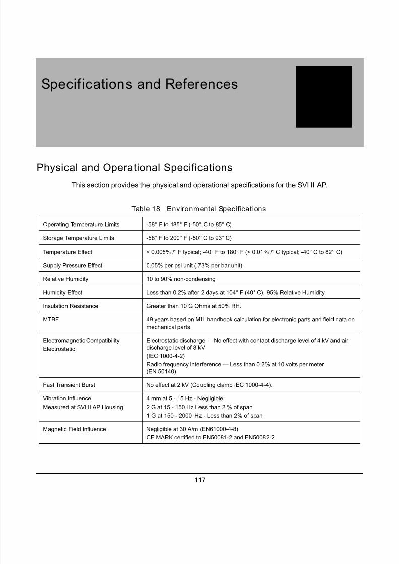
5/8/2018 EW2002 AP 0610 Web_SVI2Ap With Remote Sensor - slidepdf.com
http://slidepdf.com/reader/full/ew2002-ap-0610-websvi2ap-with-remote-sensor 129/160
117
ASpecifications and References
Physical and Operational Specifications
This section provides the physical and operational specifications for the SVI II AP.
Table 18 Environmental Specifications
Operating Temperature Limits -58°F to 185°F (-50°C to 85°C)
Storage Temperature Limits -58°F to 200°F (-50°C to 93°C)
Temperature Effect < 0.005% /°F typical; -40°F to 180°F (< 0.01% /°C typical; -40°C to 82°C)
Supply Pressure Effect 0.05% per psi unit (.73% per bar unit)
Relative Humidity 10 to 90% non-condensing
Humidity Effect Less than 0.2% after 2 days at 104° F (40°C), 95% Relative Humidity.
Insulation Resistance Greater than 10 G Ohms at 50% RH.
MTBF 49 years based on MIL handbook calculation for electronic parts and field data on
mechanical parts
Electromagnetic Compatibility
Electrostatic
Electrostatic discharge — No effect with contact discharge level of 4 kV and air
discharge level of 8 kV
(IEC 1000-4-2)
Radio frequency interference — Less than 0.2% at 10 volts per meter
(EN 50140)
Fast Transient Burst No effect at 2 kV (Coupling clamp IEC 1000-4-4).
Vibration Influence
Measured at SVI II AP Housing
4 mm at 5 - 15 Hz - Negligible
2 G at 15 - 150 Hz Less than 2 % of span
1 G at 150 - 2000 Hz - Less than 2% of span
Magnetic Field Influence Negligible at 30 A/m (EN61000-4-8)
CE MARK certified to EN50081-2 and EN50082-2

5/8/2018 EW2002 AP 0610 Web_SVI2Ap With Remote Sensor - slidepdf.com
http://slidepdf.com/reader/full/ew2002-ap-0610-websvi2ap-with-remote-sensor 130/160
SVI II AP Instruction Manual
118
D R
A F T
6 / 8 / 1 0
Dresser Masoneilan
* Specifications are subject to change without notice
Table 19 Operational Specifications*
Accuracy +/- 0.5% (typical +/-0. 10% or less) Full Span
Hysteresis and Deadband +/- 0.3% Full Span
Repeatability +/- 0.3% Full Span
Conformity +/- 0.5% Full Span
Start-Up Drift Less than 0.02% in first hour
Long Term Drift Less than 0.003% per month
Position Travel Limits Rotary: 18 - 140°
Reciprocating: 0.25” - 2.5“(12mm - 64mm)
Note: Above 2.5” (64mm) consult factory for mounting
instructions.
Flow Characteristics
Applied in addition to the control valve’s inherent
characteristic.
Linear
Equal Percentage (of 50:1 or 30:1)
Camflex
Quick Opening (inverse of 50:1 equal percentage)
User Configurable
Tight Shut Off (0 -20% of input)
Position Auto Tune
SVI II AP performs automatic determination of the
optimal valve position control parameters. In
addition to P, I, D, the position algorithm uses
damping, symmetry for exhaust and fill time
constants, dead zone and magnitudecharacterization parameters. Auto Tune is
optimized for 5% step changes with negligible
overshoot. After the Auto Tune process is
completed, You can further adjust the positioner
tuning parameters to more conservative or to more
responsive values.
Proportional gain: 0 to 5, displayed as 0 to 5000
Integral time: 0 to 100 seconds - displayed as 0 to 1000 (1/
10s)
Derivative time: 0 to 200 milliseconds
Dead Zone: 0 to +/-5% (0 to 10% deadband)
Padj: +/- 3000 (depends on P)
Beta (non-linear gain factor): -9 to +9
Stroking Time: 0 to 250 seconds
Position compensation coefficient: 1 to 20
Boost: 0 to 20
Full open position adjustment 60 to 100% of actual stop
Start Up Time (from no power) Less than 200 mS
Minimum current to maintain HART 3.0 mA
SIL SIL2 Compliant per IEC61508
HART Command #3 Mapping PV = Valve Position, 0-100%
SV = Actuator Pressure (P1-P2)
TV = Supply Pressure
QV = P2 for double acting units
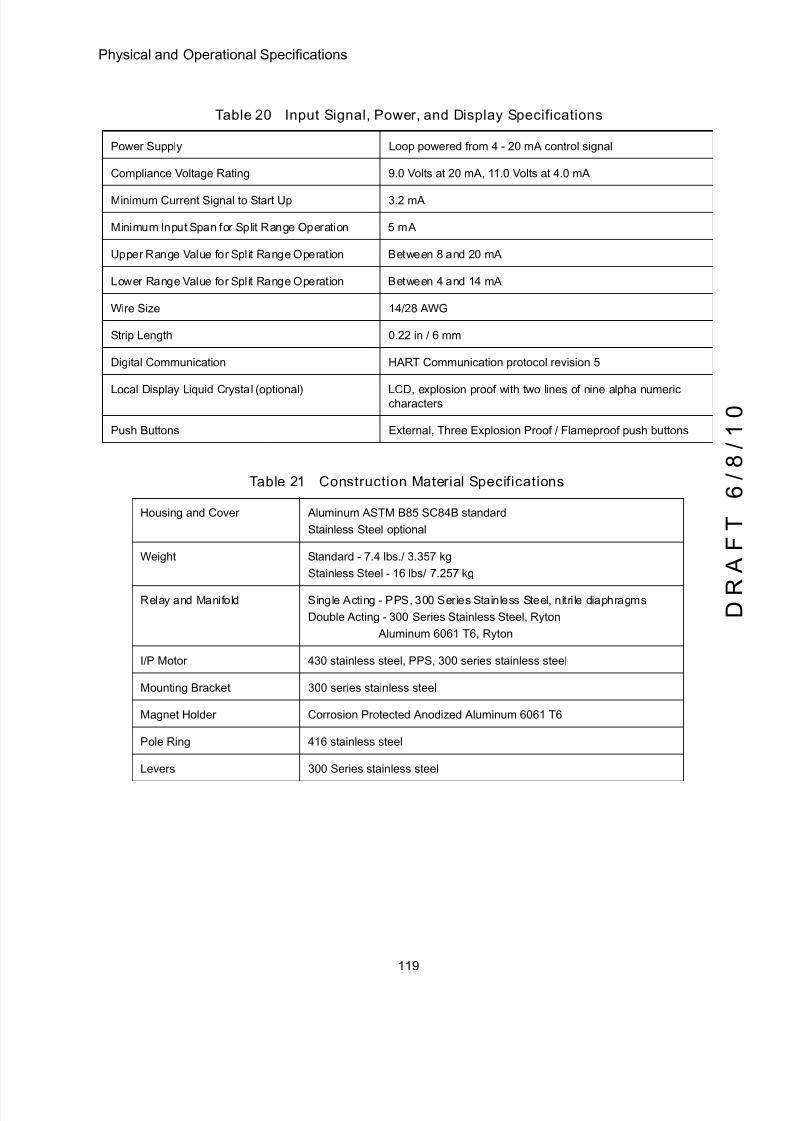
5/8/2018 EW2002 AP 0610 Web_SVI2Ap With Remote Sensor - slidepdf.com
http://slidepdf.com/reader/full/ew2002-ap-0610-websvi2ap-with-remote-sensor 131/160
119
Physical and Operational Specifications
Table 20 Input Signal, Power, and Display Specifications
Power Supply Loop powered from 4 - 20 mA control signal
Compliance Voltage Rating 9.0 Volts at 20 mA, 11.0 Volts at 4.0 mA
Minimum Current Signal to Start Up 3.2 mA
Minimum Input Span for Split Range Operation 5 mA
Upper Range Value for Split Range Operation Between 8 and 20 mA
Lower Range Value for Split Range Operation Between 4 and 14 mA
Wire Size 14/28 AWG
Strip Length 0.22 in / 6 mm
Digital Communication HART Communication protocol revision 5
Local Display Liquid Crystal (optional) LCD, explosion proof with two lines of nine alpha numericcharacters
Push Buttons External, Three Explosion Proof / Flameproof push buttons
Table 21 Construction Material Specifications
Housing and Cover Aluminum ASTM B85 SC84B standard
Stainless Steel optional
Weight Standard - 7.4 lbs./ 3.357 kg
Stainless Steel - 16 lbs/ 7.257 kg
Relay and Manifold Single Acting - PPS, 300 Series Stainless Steel, nitri le diaphragms
Double Acting - 300 Series Stainless Steel, Ryton
Aluminum 6061 T6, Ryton
I/P Motor 430 stainless steel, PPS, 300 series stainless steel
Mounting Bracket 300 series stainless steel
Magnet Holder Corrosion Protected Anodized Aluminum 6061 T6
Pole Ring 416 stainless steel
Levers 300 Series stainless steel
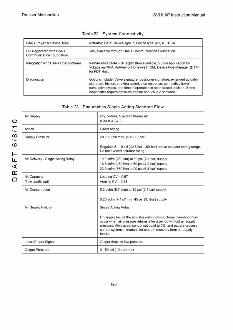
5/8/2018 EW2002 AP 0610 Web_SVI2Ap With Remote Sensor - slidepdf.com
http://slidepdf.com/reader/full/ew2002-ap-0610-websvi2ap-with-remote-sensor 132/160
SVI II AP Instruction Manual
120
D R
A F T
6 / 8 / 1 0
Dresser Masoneilan
Table 22 System Connectivity
HART Physical Device Type Actuator; HART device type 7, Device type 202, 0 , 00CA
DD Registered with HART
Communication Foundation
Yes, available through HART Communication Foundation
Integration with HART Host software ValVue AMS SNAP-ON application available, plug-in application for
Yokagawa PRM, ValVue for Honeywell FDM, Device type Manager (DTM)
for FDT Host
Diagnostics Options include: Valve signature, positioner signature, extended actuator
signature, friction, stroking speed, step response, cumulative travel,
cumulative cycles, and time of operation in near-closed position. Some
diagnostics require pressure sensor and ValVue software.
Table 23 Pneumatics Single Acting Standard Flow
Air Supply Dry, oil-free, 5 micron filtered air
(See ISA S7.3)
Action Direct Acting
Supply Pressure 20 -150 psi max. (1.4 - 10 bar)
Regulate 5 - 10 psi (.345 bar - .69 bar) above actuator spring range.
Do not exceed actuator rating.
Air Delivery - Single Acting Relay 10.0 scfm (280 l/m) at 30 psi (2.1 bar) supply
16.6 scfm (470 l/m) at 60 psi (4.2 bar) supply
23.3 scfm (660 l/m) at 90 psi (6.3 bar) supply
Air Capacity
(flow coefficient)
Loading CV = 0.57
Venting CV = 0.53
Air Consumption 0.2 scfm (5.7 sl/m) at 30 psi (2.1 bar) supply
0.26 scfm (7.4 sl/m) at 45 psi (3.1bar) supply
Air Supply Failure Single Acting Relay
On supply failure the actuator output drops. Some overshoot may
occur when air pressure returns after a period without air supply
pressure. Always set control set point to 0%, and put the process
control system in manual, for smooth recovery from air supplyfailure.
Loss of Input Signal Output drops to low pressure.
Output Pressure 0-150 psi (10 bar) max
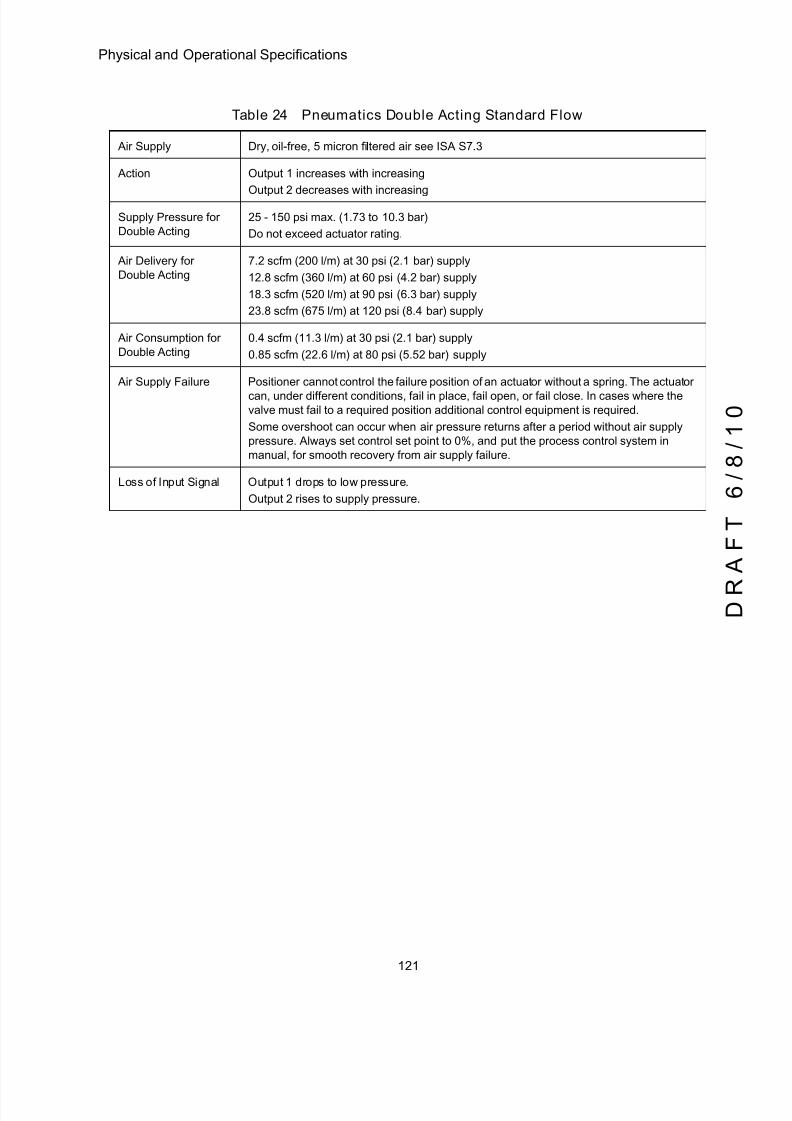
5/8/2018 EW2002 AP 0610 Web_SVI2Ap With Remote Sensor - slidepdf.com
http://slidepdf.com/reader/full/ew2002-ap-0610-websvi2ap-with-remote-sensor 133/160
121
Physical and Operational Specifications
Table 24 Pneumatics Double Acting Standard Flow
Air Supply Dry, oil-free, 5 micron filtered air see ISA S7.3
Action Output 1 increases with increasing
Output 2 decreases with increasing
Supply Pressure for
Double Acting
25 - 150 psi max. (1.73 to 10.3 bar)
Do not exceed actuator rating.
Air Delivery for
Double Acting
7.2 scfm (200 l/m) at 30 psi (2.1 bar) supply
12.8 scfm (360 l/m) at 60 psi (4.2 bar) supply
18.3 scfm (520 l/m) at 90 psi (6.3 bar) supply
23.8 scfm (675 l/m) at 120 psi (8.4 bar) supply
Air Consumption for
Double Acting
0.4 scfm (11.3 l/m) at 30 psi (2.1 bar) supply
0.85 scfm (22.6 l/m) at 80 psi (5.52 bar) supply
Air Supply Failure Positioner cannot control the failure position of an actuator without a spring. The actuator
can, under different conditions, fail in place, fail open, or fail close. In cases where thevalve must fail to a required position additional control equipment is required.
Some overshoot can occur when air pressure returns after a period without air supply
pressure. Always set control set point to 0%, and put the process control system in
manual, for smooth recovery from air supply failure.
Loss of Input Signal Output 1 drops to low pressure.
Output 2 rises to supply pressure.
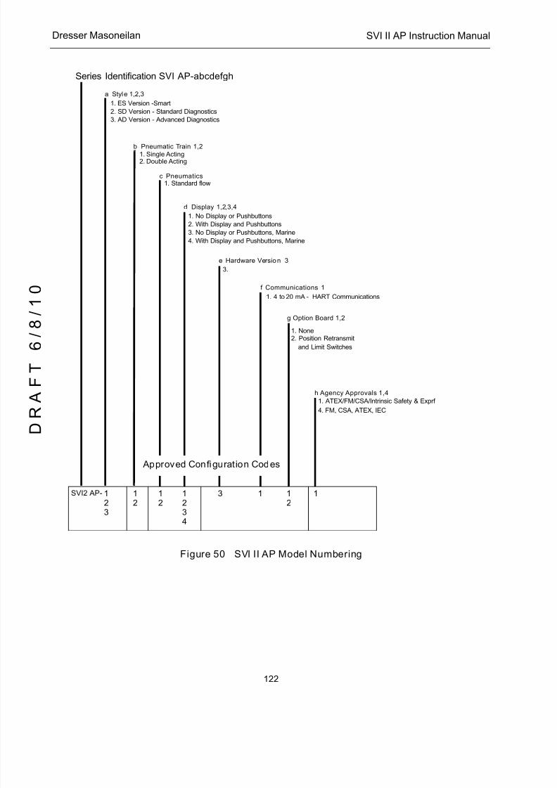
5/8/2018 EW2002 AP 0610 Web_SVI2Ap With Remote Sensor - slidepdf.com
http://slidepdf.com/reader/full/ew2002-ap-0610-websvi2ap-with-remote-sensor 134/160
SVI II AP Instruction Manual
122
D R
A F T
6 / 8 / 1 0
Dresser Masoneilan
Figure 50 SVI II AP Model Numbering
Series Identification SVI AP-abcdefgh
a Style 1,2,3
1. ES Version -Smart
2. SD Version - Standard Diagnostics
3. AD Version - Advanced Diagnostics
b Pneumatic Train 1,21. Single Acting2. Double Acting
c Pneumatics1. Standard flow
d Display 1,2,3,4
1. No Display or Pushbuttons
2. With Display and Pushbuttons
3. No Display or Pushbuttons, Marine
4. With Display and Pushbuttons, Marine
e Hardware Version 3
3.
f Communications 1
1. 4 to 20 mA - HART Communications
g Option Board 1,2
1. None2. Position Retransmit
h Agency Approvals 1,4
1. ATEX/FM/CSA/Intrinsic Safety & Exprf
4. FM, CSA, ATEX, IEC
Approved Configuration Codes
SVI2 AP- 123
12
12
1234
3 1 12
1
and Limit Switches

5/8/2018 EW2002 AP 0610 Web_SVI2Ap With Remote Sensor - slidepdf.com
http://slidepdf.com/reader/full/ew2002-ap-0610-websvi2ap-with-remote-sensor 135/160
123
Spare Parts
Spare Parts
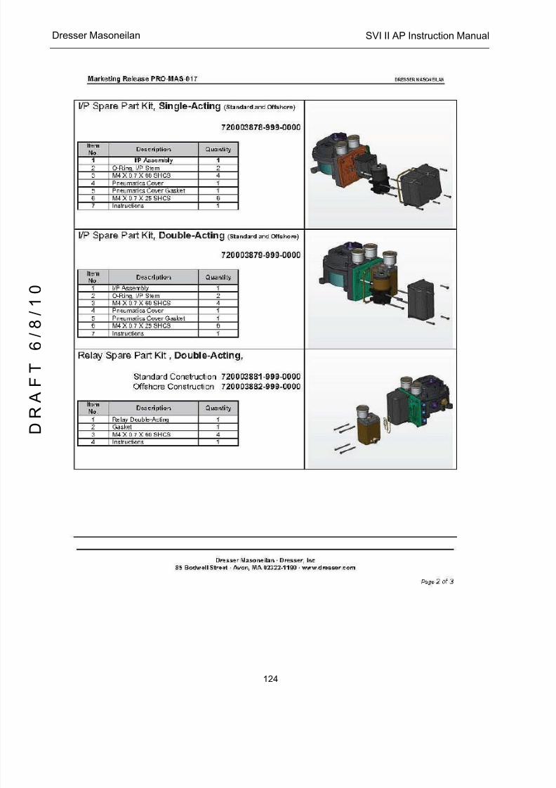
5/8/2018 EW2002 AP 0610 Web_SVI2Ap With Remote Sensor - slidepdf.com
http://slidepdf.com/reader/full/ew2002-ap-0610-websvi2ap-with-remote-sensor 136/160
SVI II AP Instruction Manual
124
D R
A F T
6 / 8 / 1 0
Dresser Masoneilan
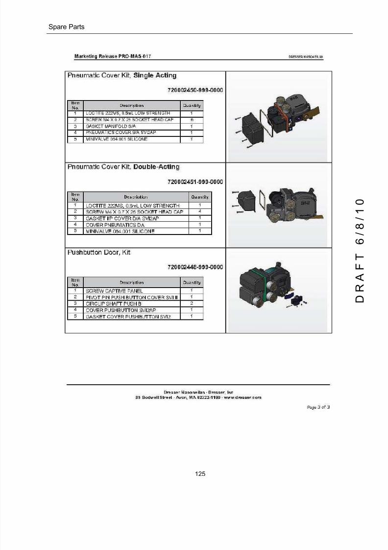
5/8/2018 EW2002 AP 0610 Web_SVI2Ap With Remote Sensor - slidepdf.com
http://slidepdf.com/reader/full/ew2002-ap-0610-websvi2ap-with-remote-sensor 137/160
125
Spare Parts

5/8/2018 EW2002 AP 0610 Web_SVI2Ap With Remote Sensor - slidepdf.com
http://slidepdf.com/reader/full/ew2002-ap-0610-websvi2ap-with-remote-sensor 138/160
SVI II AP Instruction Manual
This page intentionally left blank.
D R
A F T
6 / 8 / 1 0

5/8/2018 EW2002 AP 0610 Web_SVI2Ap With Remote Sensor - slidepdf.com
http://slidepdf.com/reader/full/ew2002-ap-0610-websvi2ap-with-remote-sensor 139/160
127
BAir to Open and Air to Close
Actuators
Actuator Action
It is important to correctly assign the sign + or - of each control variable throughout a control
system. Even the control valve subsystem can be complex. Figure 51 and Figure 52 showthe action of air to open, ATO, and air to close, ATC, valves when used with SVI II AP. The
figures show a direct acting positioner with linear and percentage characteristics. Some
hysteresis is shown for the actuator pressure signal that is caused by friction in typical
actuators. The scales are chosen to emphasize the relationships between input current and
actuator pressure, so that the failsafe valve position is shown at the lower left of each graph.
Note that for an ATC valve, 4 mA represents 100% valve travel not the expected 0%. The
controller and other human machine interfaces must correctly show that the valve is open
100% at 4 mA and closed 0% at 20. The graph shows the valve movement and actuator
pressure when the Tight Shut-off, T.S., option is set at about 5%, in this example. The valve
movement and actuator pressure are also shown at the low current lift-off point at about 3.6
mA, below which the positioner is initializing its settings until power is stabilized.

5/8/2018 EW2002 AP 0610 Web_SVI2Ap With Remote Sensor - slidepdf.com
http://slidepdf.com/reader/full/ew2002-ap-0610-websvi2ap-with-remote-sensor 140/160
SVI II AP Instruction Manual
128
D R
A F T
6 / 8 / 1 0
Dresser Masoneilan
Figure 51 ATO and ATC Action with Linear Positioner Characteristics
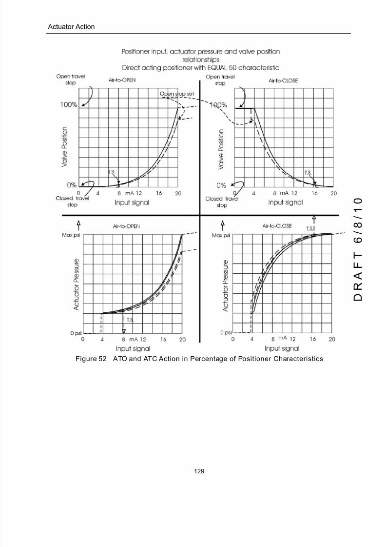
5/8/2018 EW2002 AP 0610 Web_SVI2Ap With Remote Sensor - slidepdf.com
http://slidepdf.com/reader/full/ew2002-ap-0610-websvi2ap-with-remote-sensor 141/160
129
Actuator Action
Figure 52 ATO and ATC Action in Percentage of Positioner Characteristics

5/8/2018 EW2002 AP 0610 Web_SVI2Ap With Remote Sensor - slidepdf.com
http://slidepdf.com/reader/full/ew2002-ap-0610-websvi2ap-with-remote-sensor 142/160
SVI II AP Instruction Manual
This page intentionally left blank.
D R
A F T
6 / 8 / 1 0

5/8/2018 EW2002 AP 0610 Web_SVI2Ap With Remote Sensor - slidepdf.com
http://slidepdf.com/reader/full/ew2002-ap-0610-websvi2ap-with-remote-sensor 143/160
131
CAir Supply Requirements
Air Supply Requirements
A high quality air supply greatly improves the quality of control and reduce maintenance costs
of pneumatic equipment. See ANSI ⁄ ISA-7.0.01-1996 - Quality Standard for Instrument Air. Airsupply failure requires special attention to minimize process effects. Design and apply all
process equipment to fail to a safe condition. This includes failure of the air supply. SVI II AP
is designed to fail to a condition of low or no air pressure. Choose control valve actuators to
move the valve to a safe condition when air pressure is low or absent. For example, a valve
supplying fuel to a combustion process is normally equipped with an Air to Open valve. In
other words, the fuel flow is shut off if air fails.
Additional process precautions can be taken. When the air supply recovers, the setpoint to
the valve must be at a value that continues to hold the valve in its safe condition, or to move it
to a known safe condition. To do so, put the control system sending the control valve position
setpoint into manual mode and set to 0%. After the air supply has stabilized at its correct
pressure, the setpoint can be moved to its operation point in accordance with the plant’s safe
start-up procedures. An additional precaution required on critical processes with an ATO
control valve is to install a shut-off valve that supplements the control valve by moving to a
safe condition on air failure, and remains in that condition until all necessary requirements for
safe start-up have been met.
q Keep clear of moving parts. The SVI II AP can cause the valve to move when the air
supply returns.

5/8/2018 EW2002 AP 0610 Web_SVI2Ap With Remote Sensor - slidepdf.com
http://slidepdf.com/reader/full/ew2002-ap-0610-websvi2ap-with-remote-sensor 144/160
SVI II AP Instruction Manual
This page intentionally left blank.
D R
A F T
6 / 8 / 1 0
5/8/2018 EW2002 AP 0610 Web_SVI2Ap With Remote Sensor - slidepdf.com
http://slidepdf.com/reader/full/ew2002-ap-0610-websvi2ap-with-remote-sensor 145/160
133
DAdjusting Speed of Response
Adjusting Speed of Response
The SVI II AP provides in its Calibration software the ability to automatically tune the
connected valve. The auto tune feature has robust tuning parameters designed to toleratevariations in process characteristics. You can adjust the speed of response of the control
valve by adjusting parameters in SVI II AP. Tuning parameters are adjusted by ValVue, the
preferred method, or by the HHC 375. See the ValVue Instruction Manual for details.

5/8/2018 EW2002 AP 0610 Web_SVI2Ap With Remote Sensor - slidepdf.com
http://slidepdf.com/reader/full/ew2002-ap-0610-websvi2ap-with-remote-sensor 146/160
SVI II AP Instruction Manual
This page intentionally left blank.
D R
A F T
6 / 8 / 1 0

5/8/2018 EW2002 AP 0610 Web_SVI2Ap With Remote Sensor - slidepdf.com
http://slidepdf.com/reader/full/ew2002-ap-0610-websvi2ap-with-remote-sensor 147/160
135
EAdvanced Usage
Technology to Maximize Savings and Process Performance
This section shows examples of techniques for achieving superior process results by using
ValVue with SVI II AP to simplify maintenance and to achieve the benefits of SVI II AP’sadvanced diagnostics capabilities. It is assumed that you are using HART communications
with a modem and ValVue. Refer to the ValVue Instruction Manual for complete instructions
on these and other procedures.
Tight Shutoff Application to Protect from Seat Erosion
The Tight shutoff feature can be programmed to prevent valve seat erosion using the full
actuator force to eliminate damaging leakage. At a position setpoint of 2%, for example, this
function allows full thrust to occur when the input signal is less than 2%. This solves a
common cause of valve repair. Do not use tight shutoff if it is necessary to throttle the valve at
very small flows.
Tight Shutoff Application to High Pressure Liquid Letdown Valve Trim
When staged trim is used in High Pressure Liquid Letdown Valves, Tight Shutoff can be
adjusted to move the valve from the seat to begin throttling at the minimum operable CV
level. Using the tight shut-off feature in SVI II AP prevents valve seat damage that can occur
when throttling at clearance flows. See recommended Tight Shutoff settings in the following
table. Tight shutoff can be adjusted with pushbuttons or with ValVue or a HART
communicator.
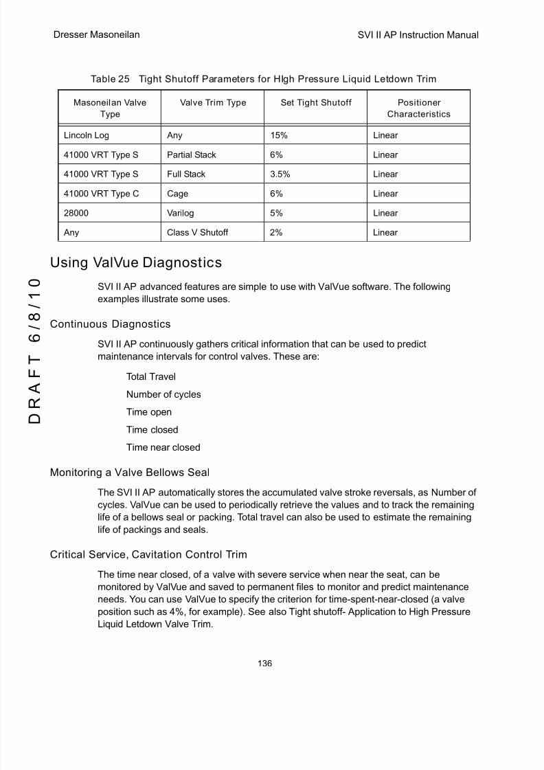
5/8/2018 EW2002 AP 0610 Web_SVI2Ap With Remote Sensor - slidepdf.com
http://slidepdf.com/reader/full/ew2002-ap-0610-websvi2ap-with-remote-sensor 148/160
SVI II AP Instruction Manual
136
D R
A F T
6 / 8 / 1 0
Dresser Masoneilan
Using ValVue DiagnosticsSVI II AP advanced features are simple to use with ValVue software. The following
examples illustrate some uses.
Continuous Diagnostics
SVI II AP continuously gathers critical information that can be used to predict
maintenance intervals for control valves. These are:
q Total Travel
q Number of cycles
q Time open
q Time closed
q Time near closed
Monitoring a Valve Bellows Seal
The SVI II AP automatically stores the accumulated valve stroke reversals, as Number of
cycles. ValVue can be used to periodically retrieve the values and to track the remaining
life of a bellows seal or packing. Total travel can also be used to estimate the remaining
life of packings and seals.
Critical Service, Cavitation Control Trim
The time near closed, of a valve with severe service when near the seat, can be
monitored by ValVue and saved to permanent files to monitor and predict maintenance
needs. You can use ValVue to specify the criterion for time-spent-near-closed (a valve
position such as 4%, for example). See also Tight shutoff- Application to High Pressure
Liquid Letdown Valve Trim.
Table 25 Tight Shutoff Parameters for HIgh Pressure Liquid Letdown Trim
Masoneilan Valve
Type
Valve Trim Type Set Tight Shutoff Positioner
Characteristics
Lincoln Log Any 15% Linear
41000 VRT Type S Partial Stack 6% Linear
41000 VRT Type S Full Stack 3.5% Linear
41000 VRT Type C Cage 6% Linear
28000 Varilog 5% Linear
Any Class V Shutoff 2% Linear

5/8/2018 EW2002 AP 0610 Web_SVI2Ap With Remote Sensor - slidepdf.com
http://slidepdf.com/reader/full/ew2002-ap-0610-websvi2ap-with-remote-sensor 149/160
137
Diagnostic Valve Tests
Diagnostic Valve Tests
The standard diagnostic test performs a full stroke test, and determines stroking speed.
The Step Response test moves the valve between several points selected by you and
graphically presents the dynamic response for each step. The Positioner Signature test
strokes the valve over a travel specified by you and records a signature for comparison
with the as-built and with future tests to predict maintenance intervals. The full version ofValVue is required for diagnostic tests.

5/8/2018 EW2002 AP 0610 Web_SVI2Ap With Remote Sensor - slidepdf.com
http://slidepdf.com/reader/full/ew2002-ap-0610-websvi2ap-with-remote-sensor 150/160
SVI II AP Instruction Manual
This page intentionally left blank.
D R
A F T
6 / 8 / 1 0
5/8/2018 EW2002 AP 0610 Web_SVI2Ap With Remote Sensor - slidepdf.com
http://slidepdf.com/reader/full/ew2002-ap-0610-websvi2ap-with-remote-sensor 151/160
139
FGlossary
Accuracy In a control valve the position is measured between mechanical motion limits
in the valve. These limits can include position variations due to actuator and
valve rigidity. therefore, accuracy is referenced to positions within normal
travel of the valve independent of rigidity effects at the mechanical limits.Accuracy is the greatest deviation from the expected position within the nor-
mal travel, expressed as percent of normal travel.
Actuator
Type
An actuator is a device that transforms an input signal (mainly an electrical
signal) into motion. A HART compliant actuator receives a 4 - 20 mA control
current signal and causes an actuation function. There are many types of
HART actuators; a positioner is type of actuator. A device of type Actuator can
not be connected to a circuit intended for a device of type Transmitter.
Algorithm An algorithm is a procedure or formula for solving a problem. There are sev-
eral algorithms entailed in SVI II AP operation. The SVI II AP has a position
control algorithm that is a modified PID. Other algorithms embedded in SVI IIAP include the STOPS method for calibrating stroke, and the autoTUNE
method for establishing the best parameters for the PID algorithm.
ATC Air to
Close
The combination of a single acting actuator and the control valve where the
valve is closed when air pressure is applied to the actuator
ATO Air to
Open
The combination of a single acting actuator and the control valve where the
valve is open when air pressure is applied to the actuator
CALIBrate A mode of the positioner in which you can change the calibration of stroke,
input signal, and tuning parameters.

5/8/2018 EW2002 AP 0610 Web_SVI2Ap With Remote Sensor - slidepdf.com
http://slidepdf.com/reader/full/ew2002-ap-0610-websvi2ap-with-remote-sensor 152/160
SVI II AP Instruction Manual
140
D R
A F T
6 / 8 / 1 0
Dresser Masoneilan
Characteristic The positioner input setpoint command can be selectively modi-
fied to provide a desired relationship between setpoint and valve
position. In the valve, the relationship between stroke and Cv is
also called valve inherent characteristic. It is often adjusted by
design, to equal percentage, for example. The positioner charac-
teristic is applied to modify the setpoint to travel relationship of
the actuator. The characteristic of the positioner must be chosen
to compliment the valve. If the valve is equal percentage, set the
positioner to linear. If a linear valve is installed the positioner can
be set to an equal percentage characteristic to improve flow con-
trol. SVI II AP offers an eleven point custom characteristic option
that can be created and edited in
ValVue. Local display can be used to select the custom charac-
teristic, but cannot adjust the points.
Closed The valve position in which the flow is minimum or zero. See tight
shutoff.
Compliance Voltage The voltage that must be available at the control system output in
order to drive the control current through the SVI II AP and all the
resistive devices in series with it.
Conformity The closeness to which the position approaches the theoretical
position curve, for example equal percentage or quick opening. It
is independent of effects due to valve or actuator rigidity at the
mechanical limits of travel. See Accuracy.
Compliance, HART Manufactured and tested in accordance with the HART Commu-
nications Foundation standards.
ConditionMonitoring
A technology for measuring the performance of process equip-ment and valves over a period of time to predict the need for
maintenance. The technology evolved to meet NRC requirements
GL 89-10, and has proven valuable to other process industries.
SVI II AP and ValVue offer a suite of diagnostic tools to implement
condition monitoring.
CONFIGure A mode of the positioner where you can change permanent
parameters required for position control or for communications.
Custom The custom characteristic in the SVI II AP has ten points to define
the (See Characteristic)relationship between the setpoint and
the valve position. The pushbuttons allow selection of the customcharacteristic that must be downloaded as pairs of data using the
HART communications from a HART master. ValVue offers a
graphical drag-and-drop method to define the characteristic. It
includes a method to correct for geometric non-linearity of the
positioner feedback linkage.
5/8/2018 EW2002 AP 0610 Web_SVI2Ap With Remote Sensor - slidepdf.com
http://slidepdf.com/reader/full/ew2002-ap-0610-websvi2ap-with-remote-sensor 153/160
141
DCS Distributed Control System is a generic term for the common con-
trol system architecture that generally performs process control in
networked computers and interacts with field devices through
rack mounted I ⁄ O cards. A positioner is usually connected to a
DCS output card which controls the 4- 20mA current to the posi-
tioner.
Device Description,
DD
The software object installed in the HART Handheld Communica-
tor HHC 375 to allow it to communicate and display the custom
parameters available in a field device.
Diagnostics The suite of software, and hardware tools that allow an SVI II AP
to monitors its own internal condition and to monitor the perfor-
mance of the control valve and actuator system. Depending on
options purchased the diagnostics can evaluate number of valve
strokes, total accumulated valve stem travel, step response times
with graphs, input to position relationships. Often system perfor-
mance signatures are obtained and retained to compare as-built
with future performance to predict remaining useful service life.
Double Acting An actuator is double acting when it has pressure applied to both
sides of the piston. A positioner is factory assembled and cali-
brated as a double acting that has two pressure outputs one that
increases and one that decreases with increasing position set-
point. The SVI II AP positioner can be single acting or double act-
ing.
EEPROM An Electrically Erasable Programmable Read Only Memory. SVI
II AP has two memories that are used for permanent storage of
data that changes during operation. The micro-controller has
EEPROM which permanently stores changing information such
as number of actuator cycles and totalized valve travel. The pro-
gram is stored in flash memory and can be upgraded.
Equal Percentage A valve characteristic designed to compensate for the loss of
pressure in a pipeline as a control valve is opened. It is intended
to linearize the installed flow versus lift characteristic for improved
control.
*The theoretical curve is y= aexln(1 ⁄ a), where a is.02, 1/R, and
R=50 for a 50:1 equal percentage characteristic. However, the
theoretical curve leaves the valve unseated by 2% at 0% input.
The actual curve, shown here, is corrected to seat the valve at
0%. The corrected curve is Y=(aexln(1 ⁄ a) -a)/(1-a).
Error Messages The positioner stores the reasons for errors. The error messages
can be read by HART or with the local display.

5/8/2018 EW2002 AP 0610 Web_SVI2Ap With Remote Sensor - slidepdf.com
http://slidepdf.com/reader/full/ew2002-ap-0610-websvi2ap-with-remote-sensor 154/160
SVI II AP Instruction Manual
142
D R
A F T
6 / 8 / 1 0
Dresser Masoneilan
Fail Safe A mode of the positioner where the valve position is controlled to
a predetermined safe position. This mode is forced by the posi-
tioner program in response to errors. If the errors are cleared then
RESET returns the positioner to the mode prior to the error.
Fatal Error In error which the SVI II AP program treats as non-recoverable.
Service is required.
Flash Memory A computer memory that is not volatile. It stores all its data even
when the power is off. It performs high speed reads and can be
re-written many times. It is used to store programs and perma-
nent parameters.
FSK Frequency Shift Keying see HART protocol.
Hall Effect Sensor A semiconductor magnetic-field sensor that measures the mag-
netic flux perpendicular to the sensor.
HART HART is an acronym for Highway Addressable Remote Trans-
ducer. The HART protocol makes use of the Bell 202 FrequencyShift Keying (FSK) standard to superimpose digital signals at a
low level on top of the 4-20mA. This enables two-way communi-
cation to take place and makes it possible for additional informa-
tion beyond just the normal process variable to be communicated
tomorrow a smart field instrument. The HART protocol communi-
cates without interrupting the 4-20mA signal and allows a host
application (master) to get two or more digital updates per second
from a field device. As the digital FSK signal is phase continuous,
there is no interference with the 4-20mA signal.
HART
Communication
The HART Communication Foundation is an independent, non-
profit foundation corporation specifically organized to coordinate
and support the application of HART technology worldwide. Edu-
cating the industry on the capabilities and value of this important
technology is a key role.
Operating costs are offset by membership and training ⁄ support
service fees. Membership is open to all suppliers, end users, and
others interested in the use of HART technology.
HART Filter A filter required with certain DCS systems that are not HART
compliant. It allows the 4 - 20 mA output signal to pass from con-
trol system to positioner, but blocks HART FSK tones from pass-
ing from the field wiring to the control system.
HART Master A device, usually a PC which is controlling the communications
over a HART protocol network. The HART master sends to a field
device a command and requires a response.
HART Slave A device, normally a transmitter or positioner, that communicates
over a HART protocol network only in response to a command
from a master.
5/8/2018 EW2002 AP 0610 Web_SVI2Ap With Remote Sensor - slidepdf.com
http://slidepdf.com/reader/full/ew2002-ap-0610-websvi2ap-with-remote-sensor 155/160
143
Hazardous Area The area of the plant where explosion hazards are present, haz-
ards such as propane gas in a refinery, or dust in a flour mill.
HHC 375 The HART Handheld Communicator supplied by Fisher-Rose-
mount. It supports the DDs for all field devices. The DDs are com-
bined into a single file and loaded into the HHC 375 memory by a
manufacturer. Memory is available in several capacities.
Hot Swapable The SVI II AP in combination with ValVue enables a very brief
Mean Time To Repair by the following process: Upload all config-
uration information from installed positioner to ValVue, then
replace the positioner and download the configuration file. Run
STOPS, and autoTUNE, and the repair is complete.
I ⁄ P Converter The current to pressure converting device. The SVI II AP sends
an analog current signal to the I ⁄ P which produces a controlled
pressure to the pneumatic amplifying relay.
ISA The Instrument Society of America. ISA develops and publishes
international standards for use in process control. See
www.isi.org.
Multidrop A variation of the HART Communications Protocol that allows
many smart field devices to draw power from and to communi-
cate over a single pair of wires. Though most suited to multiple
measurement devices, it can be used with SVI II AP to permit dig-
ital communication of setpoint as well as configuration data, to
multiple positioners or a combination of positioners and measure-
ment transmitters. Such communication may not be fast enough
for flow control.
Multiplexer Several instrument suppliers offer equipment that can be con-
nected to multiple cables to monitor and communicate with the
attached positioners and transmitters using the HART protocol.
Often the multiplexer is used with a DCS that does not support
HART.
NAMUR NAMUR is a European user association of process control tech-
nology in chemical and pharmaceutical industries. “Recommen-
dations and Worksheets are experience reports and working
documents prepared by NAMUR for its members among process
control users for facultative utilization”. NAMUR issued a recom-
mended accessory mounting for control valves (NE 14 Anschlußvon Schwenkantrieben an Armaturen 06.08.96) which describes
a method for mounting a positioner on an actuator. See at
www.namur.de.
Neodymium Iron
Boron
A magnet alloy which provides the highest energy magnetism
available in a permanent magnet.

5/8/2018 EW2002 AP 0610 Web_SVI2Ap With Remote Sensor - slidepdf.com
http://slidepdf.com/reader/full/ew2002-ap-0610-websvi2ap-with-remote-sensor 156/160
SVI II AP Instruction Manual
144
D R
A F T
6 / 8 / 1 0
Dresser Masoneilan
Non-Volatile
Memory
Computer memory that is not lost when power is turned off. Used
to permanently store calibration, configuration and diagnostic
information in SVI II AP.
NORMAL Mode The control mode for normal use of a valve positioner. The posi-
tioner receives a setpoint from a controller or DCS and applies
pressure to the actuator to move the valve to the required posi-tion.
PC As used in this manual, a personal computer or laptop running
under Windows 2000 or later operating system.
Position With a reciprocating valve, the position is the distance of the plug
from its seat, normally measured as a linear motion of the valve
or actuator stem. With a rotary valve the position is the angle of
rotation of the valve plug measured as angular rotation of the
valve shaft.
Position Limit The Actuator can be mechanically set to stop at a predetermined
position by setting an adjustment, sometimes with a handwheel
or screw stop. SVI II AP can be configured to provide the same
limits through software control of position.
Positioner Tuning The positioner requires six integer parameters to determine the
Parameters response of the positioner to a setpoint change.
Internally, the positioner uses an improved PID control algorithm
to control the valve’s position.
Tuning Parameters
P P is a dimensionless gain factor related to the proportioning
action of the algorithm. It ranges from 0 to 5000. Common valuesfor the positioner are 50 for small valves up to 4000 for large
valves.
I (0.1 sec): Integral time or reset time, is the time constant of inte-
gral control. Higher values of I cause slower integral action. Com-
mon values are 10 (1 second) to 200 (20 seconds). A value of
zero disables integral action.
D (msec): Derivative time or rate time is the time constant of deriva-
tive control expressed in milliseconds. It ranges from 0 to 200
msec. Common values are 0 to 100. A value of zero disables
derivative action.Beta Beta is a nonlinear dimensionless gain factor, ranging from -9 to
9. When beta is 0, the controller gain is linear. Otherwise the gain
is the function of error. The larger the beta, the smaller the gain
for small error. Typical beta values for a valve position controller
are between –9 and 0.

5/8/2018 EW2002 AP 0610 Web_SVI2Ap With Remote Sensor - slidepdf.com
http://slidepdf.com/reader/full/ew2002-ap-0610-websvi2ap-with-remote-sensor 157/160
145
Padj (%) Valves often have significantly different response when filling ver-
sus exhausting. The proportional gain is adjusted by adding Padj
to P when the valve is exhausting. Padj is normally less than P.
Position
Compensation
The response of the valve is different when the valve is nearly
closed Coefficient than when the valve is nearly open. The posi-
tion compensation coefficient, which is a number between 0 and9, allow the control algorithm to optimize the valve response.
Damping
Coefficient:
The valve response can be made slower for some applications. A
value of 0 gives no damping, and a value of 9 gives maximum
damping of valve motion.
Dead Zone(%): When the valve position is within the setpoint + ⁄ - the dead zone,
no additional position control is performed. This value is normally
0%, however for high friction valves (e.g. valves with graphite
packing) a higher dead zone helps avoid limit cycling due to the
stick ⁄ slip action of the valve. In these cases the dead zone chosen
might be 0.2% to 1%.
Quick Opening (see Characteristic)
Relay, Pneumatic The component that amplifies the pneumatic control signals to
provide a wide range of actuation pressure and to supply and
vent at high flow rates for responsive control.
Safe Area The area of a plant where there never is an explosion hazard
present, such as the control room or a wire marshalling rack area.
Sig Hi In the SVI II AP configuration, the input current setting at which
the valve is fully open (ATO) or fully closed (ATC)
Sig Lo In the SVI II AP configuration, the input current setting at whichthe valve is fully closed (ATO) or fully open (ATC)
Single Acting The action of a position with a single pneumatic output for opera-
tion with a spring return actuator. (see double acting).
Split Range A control configuration where a single control output is sent to two
or more control valves. Each control valve positioner is calibrated
to respond to a separate portion of the control signal. An example
is a steam valve and a cooling water valve arranged to be both
closed at 50% and the steam valve to open.
STOPS The SVI II AP runs STOPS procedure to adjust the positioner toactual valve travel. First the output pressure is reduced to zero
and the position is recorded. That position corresponds to 0%.
The output pressure is raised to its maximum based on supply
pressure. The position is recorded and corresponds to 100%.
Stroke The total range of valve travel. Often used as a verb to describe
the process of moving the valve.
5/8/2018 EW2002 AP 0610 Web_SVI2Ap With Remote Sensor - slidepdf.com
http://slidepdf.com/reader/full/ew2002-ap-0610-websvi2ap-with-remote-sensor 158/160
SVI II AP Instruction Manual
146
D R
A F T
6 / 8 / 1 0
Dresser Masoneilan
Tag The formal designator the control valve used in control loop docu-
mentation.
Tight Shutoff (TS) A positioner property which is selected and adjusted when it is
desired to prevent operation of the valve at or near the closed
position. The positioner causes all available actuator force to be
applied to the valve seat at a position set point equal to or lessthan the TS adjustable parameter. A dead band is applied to pre-
vent cycling in and out of this behavior.
ValVue ® Lite The Masoneilan software for calibration, and configuration that is
provided with every SVI II AP.
ValVue ® The full featured Masoneilan software for diagnostics, calibration,
and configuration of SVI II AP.
VDE ⁄ VDI 3845 A Standard common in Europe for mounting positioners and
accessories on rotary valve actuators.
VIEW DATA A mode of the positioner in which the configuration and calibra-tion parameters can been examined, either remotely or with the
local display.
VIEW ERR A mode of the positioner in which the error status or error mes-
sages can be examined

5/8/2018 EW2002 AP 0610 Web_SVI2Ap With Remote Sensor - slidepdf.com
http://slidepdf.com/reader/full/ew2002-ap-0610-websvi2ap-with-remote-sensor 159/160

5/8/2018 EW2002 AP 0610 Web_SVI2Ap With Remote Sensor - slidepdf.com
http://slidepdf.com/reader/full/ew2002-ap-0610-websvi2ap-with-remote-sensor 160/160
Dresser Masoneilan
Dresser, Inc., Flow Technologies
10343 Sam Houston Park Drive
Houston, Texas 77064 U.S.A
T. +1-281-671-1640
F. +1-281-671-1735
About Dresser, Inc.
Dresser Inc. is a global leader in providing highly-engineered
infrastructure products for the global energy industry.
Leading brand names within the Dresser portfolio include
Dresser Wayne® retail fueling systems, Waukesha®
natural gas-fired engines, Masoneilan® control valves,
Consolidated® pressure relief valves, and ROOTS® blowers
and rotary gas meters. The company has manufacturing
and customer service facilities strategically located
worldwide and a sales presence in more than 150 countries
www.dresser.com.
About Dresser Masoneilan
Dresser Masoneilan, headquartered in Houston, Texas, has
been the leading global partner in process control valves
and solutions for more than 100 years. A business segment
of Dresser, Inc., the company delivers customized products,
services and diagnostic solutions for oil and gas, process
and power generation applications. www.dresser.com
BELGIUMPhone: +32-2-344-0970Fax: +32-2-344-1123
BRAZILPhone: +55-11-2146-3600Fax: +55-11-2146-3610
CANADAOntarioPhone: +905-335-3529Fax: +905-336-7628
CHINAPhone: +86-10-8486-4515Fax: +86-10-8486-5305
FRANCECourbevoiePhone: +33-1-4904-9000Fax: +33-1-4904-9010
GERMANYViersenPhone: +49-2162-8170-0Fax: +49-2162-8170-280
INDIA
MumbaiPhone: +91-22-8354790Fax: +91-22-8354791NewDelhiPhone: +91-11-2-6164175Fax: +91-11-5-1659635
ITALYPhone: +39-081-7892-111Fax: +39-081-7892-208
JAPANChibaPhone: +81-43-297-9222Fax: +81-43-299-1115
KOREAPhone: +82-2-2274-0748Fax: +82-2-2274-0794
MALAYSIAPhone: +60-3-2161-0322Fax: +60-3-2163-6312
MEXICOPhone: +52-5-310-9863Fax: +52-5-310-5584
THENETHERLANDSPhone: +0031-15-3808666Fax: +0031-18-1641438
RUSSIAVelikyNovgorodPhone: +7-8162-55-7898
Fax: +7-8162-55-7921MoscowPhone: +7495-585-1276Fax: +7495-585-1279
SAUDIARABIAPhone: +966-3-341-0278Fax: +966-3-341-7624
SINGAPOREPhone: +65-6861-6100Fax: +65-6861-7172
SOUTHAFRICAPhone: +27-11-452-1550Fax: +27-11-452-6542
SOUTH&CENTRALAMERICAANDTHECARIBBEANPhone: +55-12-2134-1201Fax: +55-12-2134-1238
SPAINPhone: +34-93-652-6430Fax: +34-93-652-6444
UNITEDARABEMIRATESPhone: +971-4-8139-200Fax: +971-4-8838-038
UNITEDKINGDOMWooburnGreenPhone: +44-1628-536300
Fax: +44-1628-536319
UNITEDSTATESMassachusettsPhone: +1-508-586-4600Fax: +1-508-427-8971CorpusChristi,TexasPhone: +1-361-881-8182Fax: +1-361-881-8246DresserDirectDeerPark,TexasPhone: +1-281-884-1000Fax: +1-281-884-1010DresserFlowTechnologiesHouston,TexasPhone: +1-281-671-1640Fax: +1-281-671-1735CaliforniaPhone: +1-562-941-7610Fax: +1-562-941-7810
DIRECT SALES OFFICE LOCATIONS