evoqua water technologies llc, final rcra permit ......pdtp performance demonstration test plan pfd...
TRANSCRIPT
PERMIT ATTACHMENT
APPENDIX XXII
STARTUP, SHUTDOWN, MALFUNCTION PLAN
This document was not altered from the April 2016 Application
September 2018
Evoqua Water Technologies – Parker, AZRCRA Permit Application
APPENDIX XXII, SSMP Rev. 1June 2014
APPENDIX XXII
STARTUP, SHUTDOWN, MALFUNCTION PLAN
EVOQUA WATER TECHNOLOGIES
PARKER REACTIVATION FACILITY
PARKER, ARIZONA
Revision 1June 2014
STARTUP, SHUTDOWN, AND MALFUNCTION PLAN
EVOQUA WATER TECHNOLOGIES 2523 MUTAHAR STREET
PARKER, ARIZONA 85344
JUNE, 2014 REVISION: 1
Evoqua Water Technologies SSMP
Revision: 1 June 2014
Evoqua SSMP Verbiage Rev 1 June 2014.doc 1-2
Tables of Contents
1.0 INTRODUCTION ................................................................................................................1-6
2.0 PLAN ORGANIZATION AND OBJECTIVES......................................................................2-1
3.0 CARBON REACTIVATION PROCESS DESCRIPTION ....................................................3-1
3.1 CARBON REACTIVATION SYSTEM........................................................................3-1
3.1.1 Primary Combustion Chamber (Multiple Hearth Furnace) ...........................3-1
3.1.2 Secondary Combustion Chamber (Afterburner)...........................................3-2
3.1.3 Residence Time Determination ....................................................................3-2
3.2 BURNER AND FEED SYSTEMS..............................................................................3-2
3.2.1 Burner Description........................................................................................3-2
3.2.2 Spent Activated Carbon Feed System .........................................................3-3
3.2.3 Auxiliary Fuel System...................................................................................3-3
3.2.4 Combustion Air .............................................................................................3-3
3.3 REACTIVATED CARBON HANDLING SYSTEM .....................................................3-3
3.4 AIR POLLUTION CONTROL (APC) SYSTEM..........................................................3-3
3.4.1 Quench/Venturi Scrubber .............................................................................3-4
3.4.2 Packed Bed Scrubber...................................................................................3-4
3.4.3 Wet Electrostatic Precipitator .......................................................................3-4
3.4.4 ID Fan...........................................................................................................3-5
3.4.5 Stack.............................................................................................................3-5
3.5 PROCESS MONITORING, CONTROL, AND OPERATION.....................................3-5
3.5.1 Process Continuous Monitoring System (CMS)...........................................3-6
3.5.2 Continuous Emissions Monitoring System (CEMS) .....................................3-8
3.5.3 Process Control System...............................................................................3-8
3.5.4 Safety and Automatic Waste Feed Cutoffs ..................................................3-9
3.6 PROCEDURES TO RAPIDLY STOP SPENT ACTIVATED CARBON FEEDS AND CONTROL EMISSIONS ...................................................................................3-9
3.6.1 Rapidly Stopping Spent Activated Carbon Feeds ........................................3-9
3.6.2 Shutting Down the System .........................................................................3-10
3.6.3 Controlling Emissions During Equipment Malfunctions..............................3-10
3.6.4 Emergency Safety Vent Operations ...........................................................3-11
4.0 SSMP IMPLEMENTATION.................................................................................................4-1
4.1 APPLICABILITY ........................................................................................................4-1
4.1.1 Startup ..........................................................................................................4-1
4.1.2 Shutdown......................................................................................................4-1
4.1.3 Malfunction ...................................................................................................4-1
Evoqua Water Technologies SSMP
Revision: 1 June 2014
Evoqua SSMP Verbiage Rev 1 June 2014.doc 1-3
4.2 FOLLOWING THE STARTUP, SHUTDOWN, AND MALFUNCTION PLAN ............4-1
4.3 METHODOLOGY FOR IDENTIFICATION OF MALFUNCTIONS ............................4-2
4.4 DOCUMENTATION OF COMPLIANCE WITH THE SSMP ......................................4-3
4.5 PROCEDURE DEVELOPMENT AND MAINTENANCE ...........................................4-3
4.6 AUTOMATIC WASTE FEED CUTOFF SYSTEM REQUIREMENTS DURING MALFUNCTIONS ......................................................................................................4-3
4.7 PROJECTED OXYGEN CORRECTION FACTOR ASSOCIATED WITH STARTUP AND SHUTDOWN...................................................................................4-4
5.0 DECISIONS, ACTIONS, AND RECORDS ASSOCIATED WITH STARTUPS, SHUTDOWNS, OR MALFUNCTIONS..........................................................................................5-1
6.0 STARTUP AND SHUTDOWN PROCEDURES..................................................................6-2
6.1 STARTUP PROCEDURES .......................................................................................6-2
6.2 SHUTDOWN PROCEDURES...................................................................................6-2
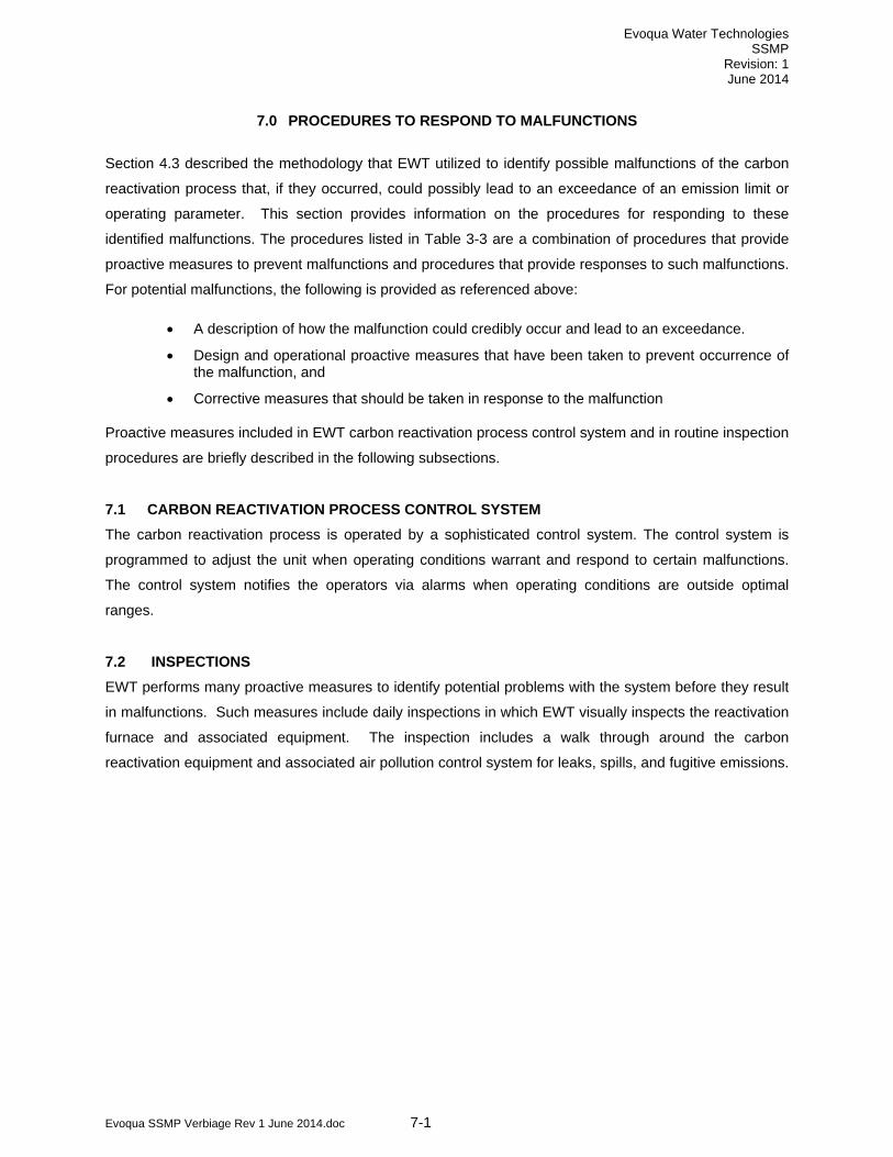
7.0 PROCEDURES TO RESPOND TO MALFUNCTIONS......................................................7-1
7.1 CARBON REACTIVATION PROCESS CONTROL SYSTEM ..................................7-1
7.2 INSPECTIONS ..........................................................................................................7-1
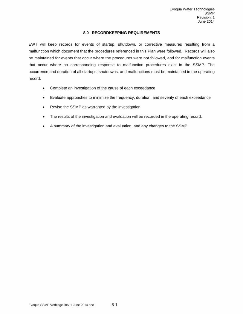
8.0 RECORDKEEPING REQUIREMENTS..............................................................................8-1
9.0 REPORTING REQUIREMENTS ........................................................................................9-1
9.1 PERIODIC STARTUP, SHUTDOWN, AND MALFUNCTION REPORTS.................9-1
9.2 IMMEDIATE STARTUP, SHUTDOWN, AND MALFUNCTION REPORTS ..............9-1
9.3 INVESTIGATION AND EVALUATION SUMMARY REPORT...................................9-1
List of Tables
Table 3-1 Summary of Key Regulatory CMS Instrumentation
Table 3-2 Summary of Operational Control Parameter Limits
Table 3-3 Potential Malfunctions of the Spent Activated Carbon Reactivation Furnace That May
Result in Exceedances
List of Figures
Figure 3-1 Spent Activated Carbon Reactivation Furnace Block Flow Diagram
Figure 3-2 Location of Critical CMS Parameter Instruments
List of Appendices
Exhibit A-1. Example SSMP Compliance Documentation Form

Evoqua Water Technologies SSMP
Revision: 1 June 2014
Evoqua SSMP Verbiage Rev 1 June 2014.doc 1-4
List of Acronyms
acfh Actual cubic feet per hour
acfm Actual cubic feet per minute
APC Air pollution control
AWFCO Automatic waste feed cutoff
Btu British thermal unit
CAA Clean Air Act
CEM or CEMS Continuous emission monitor or Continuous emission monitoring system
CFR Code of Federal Regulations
CMS Continuous monitoring system
CO Carbon monoxide
CRIT Colorado River Indian Tribes
cu. ft. Cubic foot
DC Direct current
DRE Destruction and removal efficiency
dscf Dry standard cubic foot
dscfm Dry standard cubic feet per minute
EPA United States Environmental Protection Agency
ESV Emergency Stack Vent
ft Feet
gpm U.S. Gallons per minute
gr Grain (equals 1/7000 pound)
HAP Hazardous air pollutant
HCl Hydrogen chloride
hr Hour
ID Induced draft
in Inch
in w.c. Inches of water column (pressure measurement)
L Liter
lb Pound
mg Milligram
ml Milliliter
MTEC Maximum theoretical emission concentration
NDIR Non-dispersive infrared
ng Nanogram
P&ID Piping and instrumentation diagram

Evoqua Water Technologies SSMP
Revision: 1 June 2014
Evoqua SSMP Verbiage Rev 1 June 2014.doc 1-5
PCDD/PCDF Polychlorinated dibenzo-p-dioxins and polychlorinated dibenzo furans
PDT Performance Demonstration Test
PDTP Performance Demonstration Test Plan
PFD Process flow diagram
PLC Programmable logic controller
POTW Publicly Owned Treatment Works
ppm Parts per million
ppmv Parts per million by volume
ppmvd Parts per million by volume, dry basis
RCRA Resource Conservation and Recovery Act
rpm Revolution per minute
scfm Standard cubic feet per minute
EWT Evoqua Water Technologies
SOP Standard Operating Procedure
sq. ft. Square feet
SSMP Startup, Shutdown, and Malfunction Plan
TCDD Tetrachloro dibenzo-p-dioxin
TEQ Toxicity equivalent (related to 2,3,7,8-TCDD)
TSCA Toxic Substances Control Act
ug Microgram
USEPA United States Environmental Protection Agency
WESP Wet electrostatic precipitator
Evoqua Water Technologies SSMP
Revision: 1 June 2014
Evoqua SSMP Verbiage Rev 1 June 2014.doc 1-6
1.0 INTRODUCTION
Evoqua Water Technologies (EWT) operates a carbon reactivation facility located in the Colorado River
Indian Tribes (CRIT) Industrial Park near Parker, Arizona. The facility treats spent activated carbon that
has been used by industry, state and federal government agencies, and municipalities for the removal of
organic compounds from liquid and vapor phase process waste streams. Once the carbon has been
used and is spent, it must be either disposed of or reactivated at a facility such as EWT. A Carbon
Reactivation Furnace (RF-2) is used by EWT to reactivate the spent carbon. Some of the carbon
received at the Parker facility is designated as a hazardous waste under the Resource Conservation and
Recovery Act (RCRA) regulations. Much of the spent activated carbon received at the facility is not a
RCRA hazardous waste, as it is neither a characteristic nor a listed waste as defined by 40 CFR 261.
The carbon reactivation facility is operating under the RCRA Interim Status standards of 40 CFR 265 and
is currently in the process of obtaining a RCRA permit.
The carbon reactivation process thermally treats spent activated carbon in a multiple hearth furnace
consisting of five hearths. The spent carbon is introduced into the top hearth and flows downward
through the remaining four hearths. Reactivated carbon exits the bottom hearth through a cooling screw.
Natural gas burners are provided to ensure adequate heat input to the reactivation unit for all of the spent
carbons that are reactivated at the facility. The hot gases generated in the reactivation furnace are routed
to an afterburner to ensure the thermal oxidation of any organic matter that is not oxidized in the
reactivation unit. The afterburner is equipped with two burners that utilize natural gas as the fuel source.
From the afterburner, the gases are quenched by direct water contact and routed through a variable
throat venturi scrubber for particulate matter control. From the venturi scrubber, the gases are routed to a
packed bed scrubber for acid gas control. From the packed bed scrubber, the gases flow through a wet
electrostatic precipitator, used for fine particulate matter and metals control. From the wet electrostatic
precipitator, the gases are routed through a stack to the atmosphere. The motive force for moving the
gases through the air pollution control system is supplied by an induced draft fan. The air pollution
control equipment uses a closed loop recycle water system. Scrubber blowdown from reactivation
furnace air pollution control equipment is treated in an exempt wastewater treatment unit, or discharged
directly to a Publicly Owned Treatment Works (POTW).
RF-2 is not a hazardous waste incinerator. “Incinerator” is defined in 40 CFR 260.10 as “any enclosed
device that: (1) Uses controlled flame combustion and neither meets the criteria for classification as a
boiler, sludge dryer or carbon regeneration unit, nor is listed as an industrial furnace; or (2) Meets the
definition of infrared incinerator or plasma arc incinerator.” The multiple hearth furnace is designated by
Subpart X of the RCRA regulations as a Miscellaneous Unit.

Evoqua Water Technologies SSMP
Revision: 1 June 2014
Evoqua SSMP Verbiage Rev 1 June 2014.doc 1-7
EPA Region 9 has requested that EWT prepare a Startup, Shutdown and Malfunction Plan (SSMP) as
part of the permitting process for the reactivation furnace. The purpose of the SSMP, which will take
effect once the final Part B permit is approved, is to do the following:
• To ensure that the reactivation furnace unit, including emission control equipment is operated
and maintained in fulfillment of EWT’s general duty to minimize emissions to the greatest
extent in a manner consistent with good air pollution control practices
• To ensure that owners and operators are prepared to correct malfunctions as soon as
practicable
• To minimize the reporting burden associated with excess emissions. The SSMP should
address startup, shutdown, and malfunction events of the thermal treatment process that
could result in an emission or operating limit exceedance
To meet these SSMP objectives, this Plan includes a description of:
• Procedures for operating and maintaining the source during periods of startup, shutdown, and malfunction
• The corrective action program for responding to malfunctioning process, air pollution control, and related monitoring equipment used to comply with the SSMP standard
• Potential causes of the identified malfunctions that may result in excess emissions of hazardous air pollutants (HAPs), and actions to be taken to minimize the frequency and severity of those malfunctions
Emission standards and operating limits do not apply during periods of startup, shutdown, and
malfunction. Facilities are exempted from emission standard and operating limit violations during startup,
shutdown, and malfunction events, provided the SSMP procedures are followed and compliance with the
SSMP is properly documented. The specific procedures that address startup, shutdown, and response to
possible malfunctions of the thermal treatment process, and how facility personnel must document
compliance with these procedures, are described in this plan.
In order to ensure that the plan comprehensively identifies potential malfunctions, the plant’s reaction to
those malfunctions, and the measures in place to prevent them, a EWT cross-functional team reviewed
the process and its operational factors via the following:
• independent consideration of the malfunction potential and impact of each relevant piece in
the APC system
• planned actions to be taken in response to malfunctions, and
• a determination of the scope and adequacy (with adjustment as needed) of the measures in
place to prevent malfunctions from occurring
Evoqua Water Technologies SSMP
Revision: 1 June 2014
Evoqua SSMP Verbiage Rev 1 June 2014.doc 1-8
The cross-functional team consisted of and obtained input from staff in the operations, maintenance, and
environmental departments of the Parker facility. In addition, consultative support on this effort was
provided via internal corporate and external resources.

Evoqua Water Technologies SSMP
Revision: 1 June 2014
Evoqua SSMP Verbiage Rev 1 June 2014.doc 2-1
2.0 PLAN ORGANIZATION AND OBJECTIVES
This SSMP has been developed to provide guidance for operating and maintaining the spent carbon
thermal treatment process during startup, shutdown, and occurrence of malfunctions in a manner
consistent with safety and good air pollution control practices for minimizing emissions. Preventative
measures as well as corrective measures associated with the malfunctions are also key aspects of this
Plan. The SSMP is organized as follows:
• Section 3.0 provides a description of EWT’s spent carbon reactivation process
• Section 4.0 defines startup, shutdown, and malfunction as they apply to this Plan, and provides details for complying with the plan. Instructions for preparing new Plan procedures and revising existing procedures are also discussed.
• Section 5.0 describes the decisions, actions and required records associated with the occurrence of startups, shutdowns, or potential malfunction events
• Section 6.0 describes procedures to be followed during startup and shutdown of the thermal treatment process.
• Section 7.0 addresses features of the thermal treatment process intended to prevent system malfunctions, and corrective measures to be taken in the event of malfunctions.
• Section 8.0 describes the SSMP record keeping requirements
• Section 9.0 describes the SSMP reporting requirements.
Evoqua Water Technologies SSMP
Revision: 1 June 2014
Evoqua SSMP Verbiage Rev 1 June 2014.doc 3-1
3.0 CARBON REACTIVATION PROCESS DESCRIPTION
Provided in this section is a general process description of the carbon reactivation process. Included are
functional descriptions of each system component as they apply to achieving compliance with the
emission limits and operating parameter limits. A block flow diagram of EWT’s carbon reactivation
system is provided as Figure 3-1. This section also includes a discussion of hazardous waste residence
time, which is a critical parameter associated with implementation of this plan.
3.1 CARBON REACTIVATION SYSTEM The carbon reactivation system is a multiple hearth furnace, consisting of five hearths followed by an
afterburner. Spent carbon in an aqueous slurry form is introduced into the top hearth of the reactivation
unit by a dewatering screw and flows downward through the remaining four hearths. The top two hearths
are unfired hearths. Hot combustion gases generated in the bottom three hearths flow upward through
the top hearths and are used to complete the dewatering of the spent carbon. The bottom three hearths
are fired hearths where the reactivation process occurs. Rabble arms, with teeth, each connected to a
rotating center shaft, are located above each hearth. The rabble arms plow the carbon material across
the hearth surface and towards drop holes. The carbon falls through the drop holes to the next lower
hearth, and eventually to the outlet of the reactivation unit. Reactivated carbon exits the bottom hearth
through a cooling screw. The reactivation furnace is equipped with a primary combustion air fan, and two
center shaft cooling fans. Natural gas burners are provided to ensure adequate heat input to the
reactivation unit for all carbons that are reactivated at the facility. A Performance Demonstration Test was
conducted at the reactivation furnace unit, and demonstrated compliance with all of the performance and
emissions standards in 40 CFR 60, Subpart EEE, while processing 3,049 pounds per hour of wet spent
carbon feed.
3.1.1 Multiple Hearth Furnace
Following dewatering the spent granular carbon is fed to the top section of the multiple-hearth furnace. In
the pre-drying and drying zones (the top hearths), the water retained in the pores and the surface of the
carbon is evaporated by the counter-current flow of hot combustion gases coming from the lower hearths.
The temperature of the carbon in the top hearths is raised to approximately 210°F. Upon application of
heat, water will evaporate freely when the particle temperature goes over 200°F. The adsorbed water is
freed at temperatures of approximately 212°F to 230°F. After the water is evaporated from the carbon,
the carbon starts to increase in temperature.
At temperatures over 600°F, high molecular weight organic impurities in the carbon will crack to produce
gaseous hydrocarbons, hydrogen and water vapor which escape the pores of the granular carbon. Some
fixed carbon is formed by pyrolytic (low oxygen) cracking of the organic and is retained in the pores of the
granules. In these pre-heating and decomposition zones (middle hearths) the temperature of the carbon
Evoqua Water Technologies SSMP
Revision: 1 June 2014
Evoqua SSMP Verbiage Rev 1 June 2014.doc 3-2
is increased to about 750°F in a virtually oxygen-free atmosphere. Under these conditions the adsorbed
organic impurities in the pores of the carbon are pyrolyzed and all volatile materials are driven off.
3.1.2 Afterburner
The afterburner is a self supporting vertical cylindrical chamber approximately 33 feet high with an inside
diameter of approximately 5 feet. The design incorporates a mixing zone, choke ring and a minimum
residence time, at temperature, of greater than one second. The afterburner shell is constructed of steel
plate and is internally lined with firebrick and castable insulation. The afterburner is equipped with two
low NOx burners, which utilize heated combustion air. The afterburner chamber is fitted with a total of six
air injection nozzles which are placed to provide combustion air and turbulence to promote the oxidation
of organic materials in the flue gas from the multiple hearth furnace. The afterburner is designed to
thermally oxidize greater than 99.99 percent of all organic matter entering the afterburner in the furnace
off gas. A cross section of the afterburner and the afterburner specification can be found in Appendix X of
the RCRA Part B Permit Application.
3.1.3 Residence Time Determination
The hazardous waste residence time for the carbon reactivation process following waste feed cutoff,
based on calculations of the time for spent activated carbon to exit the bottom hearth and emitted gases
to be treated in the afterburner, is 38 minutes at a rabble arm shaft speed of approximately 1 revolution
per minute (rpm).
The hazardous waste residence time is a critical parameter for establishing, following automatic or
manual shutoff of the spent carbon, whether exceedances from permit limits are or could be counted as
permit violations. Additional discussion of the significance of hazardous waste residence time as it
applies to this SSMP is provided in Section 4.0.
3.2 BURNER AND FEED SYSTEMS Six natural gas burners are installed in the reactivation furnace, two per hearth on hearths 3, 4, and 5.
Two natural gas burners are installed in the afterburner. Depending on temperature requirements in the
unit, not all burners will be required to be operated at any one time.
3.2.1 Burner Description
The six burners installed in the reactivation furnace are North American Manufacturing Company burners
(NA 6422-6) or equivalent. The two burners installed in the afterburner are North American Manufacturing
Company burners (NA 6514-8B) or equivalent. Literature describing these burners can be found in
Appendix X of the RCRA Part B Permit Application.

Evoqua Water Technologies SSMP
Revision: 1 June 2014
Evoqua SSMP Verbiage Rev 1 June 2014.doc 3-3
3.2.2 Spent Activated Carbon Feed System
The spent activated carbon feed system to the reactivation furnace consists of a feed tank, a dewatering
screw, and a weigh belt conveyor. The spent carbon/recycle water slurry is discharged from the feed
tank to the dewatering screw via a control valve. The dewatered spent carbon is discharged from the
dewatering screw on to the weigh belt conveyor, which is used to measure the feed rate to the
reactivation furnace.
3.2.3 Auxiliary Fuel System
The six burners in the reactivation furnace and the two burners in the afterburner are fired with natural
gas, supplied by the local utility company via pipeline.
3.2.4 Combustion Air
Combustion air is supplied to the six reactivation furnace burners and two afterburner burners by a
combustion air blower. The blower is designed to supply approximately 351,600 actual cubic feet per
hour (acfh) of preheated combustion air. Fan specifications are located in Appendix X of the RCRA Part
B Permit Application.
3.3 REACTIVATED CARBON HANDLING SYSTEM The reactivated carbon exiting from the reactivation furnace is a product and hence not regulated under
RCRA. No solid residues are produced by the reactivation furnace. The reactivated carbon is discharged
from the reactivation furnace into a screw cooler and from the screw cooler into one of three reactivated
carbon product storage tanks. From the reactivated carbon storage tanks, the reactivated carbon product
is transported through an enclosed conveyor to a product packaging facility. At the product packaging
facility, the reactivated carbon is removed from the storage tanks and placed in appropriate containers for
shipment to customers.
Scrubber blowdown from the reactivation furnace air pollution control equipment is treated in a RCRA-
exempt wastewater treatment unit, or discharged directly to the POTW. The discharge to the POTW is
continuously monitored for pH, total dissolved solids, flow and temperature to ensure compliance with the
discharge limitations found in the facility's industrial wastewater discharge permit.
3.4 AIR POLLUTION CONTROL (APC) SYSTEM The APC system for the reactivation furnace includes a quench/venturi scrubber, a packed bed scrubber
and a wet electrostatic precipitator. The APC system does not include an Emergency Stack Vent (ESV).
Exhaust gases from the carbon reactivation system are continuously routed through the APC equipment,
and cannot by-pass the APC equipment under any circumstances. The individual components of the
APC equipment are described in the following sections.

Evoqua Water Technologies SSMP
Revision: 1 June 2014
Evoqua SSMP Verbiage Rev 1 June 2014.doc 3-4
3.4.1 Quench/Venturi Scrubber
The Quench/Venturi Scrubber is a dual-purpose device used to rapidly quench the hot combustion gases
exiting the afterburner and to remove particulate matter. The quench section uses water sprays to cool
the afterburner exit gas to the point of adiabatic saturation (approximately 170 to 190°F). The venturi
scrubber has an adjustable throat, and is a low energy, vertical down flow type. The throat area is
adjusted by a pneumatic cylinder actuator and an electro/pneumatic positioner. The remotely adjustable
throat is automatically controlled to maintain a constant pressure differential. The venturi scrubber is
located directly below the quench section and is connected by a flooded elbow to the packed bed
scrubber. The elbow incorporates a water-filled gas impact section directly beneath the throat to prevent
erosion of the shell. The water supply for venturi irrigation is recirculated scrubber water at a total flow of
approximately 7.5 gpm/1000 acfm.
The design data and equipment descriptions for the Quench/Venturi Scrubber as well as a description of
the physical dimensions of the venturi scrubber section can be found in Appendix X of the RCRA Part B
Permit Application.
3.4.2 Packed Bed Scrubber
The packed bed scrubber consists of a vertical up flow and cylindrical disengaging section followed by a
packed bed section and mist eliminator. The bottom portion of the scrubber is used to separate entrained
water droplets from the gas prior to entering the packed section of the scrubber. The packed bed
scrubber is designed to remove a minimum of 99 percent of the incoming hydrogen chloride.
The design data and equipment description for the packed bed scrubber as well as a description of the
physical dimensions of the packed bed scrubber can be found in Appendix X of the RCRA Part B Permit
Application.
3.4.3 Wet Electrostatic Precipitator
The wet electrostatic precipitator (WESP) is a vertical tubular design with self irrigating tubes. The WESP
consists of inlet gas distribution to promote even distribution of the process gas flow entering the WESP,
inlet and outlet plenums and a collecting electrode tube bundle. The WESP is equipped with outboard
high voltage insulator compartments which include a purge air system, high voltage distribution-support
grids, high intensity rigid tube type charging/precipitating discharge electrodes, high voltage power supply
(transformer/rectifier and controller) system, ground sticks, safety key interlocks, warning labels, and
electronic control logic equipment and valving.
The WESP, in conjunction with the venturi scrubber, is designed to achieve a maximum outlet particulate
matter grain loading of 0.015 grains/dscf adjusted to 7 percent oxygen. The design data and equipment

Evoqua Water Technologies SSMP
Revision: 1 June 2014
Evoqua SSMP Verbiage Rev 1 June 2014.doc 3-5
description for the WESP as well as a description of the physical dimensions of the WESP can be found
in Appendix X of the RCRA Part B Permit Application.
3.4.4 ID Fan
A variable speed induced draft fan is provided to exhaust combustion gases from the furnace and
afterburner and through the air pollution control system. Design specifications for the fan can be found in
Appendix X of the RCRA Part B Permit Application.
3.4.5 Stack
The cleaned gas stream is exhausted to the atmosphere via a 110 foot high stack with an inside diameter
of two feet and a gas outlet that is 19.75 inches in diameter. A stack drawing is provided in Appendix X of
the RCRA Part B Permit Application.
3.5 PROCESS MONITORING, CONTROL, AND OPERATION The facility is equipped with a programmable logic control (PLC) system which monitors and/or controls
process variables to ensure proper facility operation. The reactivation furnace system is equipped with
instrumentation to monitor and control process flows, temperatures, and pressures, and to transmit
signals to the main control system. The automation system has the capabilities of controlling valves,
motors, pumps, and fans as well as alarming and initiating waste feed cutoff interlocks if process
conditions deviate from established limits.
Figure 3-2 shows the location of pertinent instrumentation related to permit compliance. Complete Piping
and Instrumentation Diagrams (P&IDs) are included in Appendix VI of the RCRA Part B Permit
Application. It is important to note that these drawings include many components of the facility that are
exempt from permitting under various provisions of RCRA. These components are provided for
informational purposes and ease of review only, and they are not intended to become regulated
components of the facility. Information concerning major process instruments associated with regulatory
compliance is presented in Table 3-1. Calibration schedules are based on manufacturer’s
recommendations and EWT operating experience.
Process monitoring and emissions monitoring performed for regulatory compliance is conducted on a
continuous basis in accordance with USEPA definitions of continuous monitors.
A “Continuous Monitor” is a device (or series of devices) which continuously samples the regulated
parameter without interruption, evaluates the detector response at least once every 15 seconds, and
computes and records the average value at least every 60 seconds, except during periods of calibration
or as otherwise allowed by the applicable regulations or guidelines. For many parameters, rolling
averages are calculated. A “Rolling Average” is defined as the arithmetic mean of a defined number of
Evoqua Water Technologies SSMP
Revision: 1 June 2014
Evoqua SSMP Verbiage Rev 1 June 2014.doc 3-6
the most recent one-minute average values calculated by the continuous monitor. For example, an
hourly rolling average would incorporate the 60 most recent one-minute average values. As each new
one-minute average value is computed, the least recent of the 60 values is discarded and a new hourly
rolling average is calculated and recorded. Twelve hour rolling averages use 720 one-minute average
values rather than 60.
Two subsets of continuous monitoring systems are employed on the reactivation furnace: process
continuous monitoring systems (CMS) and continuous emissions monitoring systems (CEMS). The
following is a discussion of each type of continuous monitoring system.
3.5.1 Process Continuous Monitoring System (CMS)
The carbon reactivation process utilizes a continuous monitoring system (CMS) to monitor regulated
stack gas emissions and operating parameters. The CMS consists of a combination of continuous
emissions monitoring systems (CEMS) and instruments (parameter CMSs) that monitor and record
parameter data from the operations of the process.
Parameter CMSs are process instruments that continuously monitor and record parameter data from the
operation of the carbon reactivation process. The instruments consist of weigh belts, flowmeters,
pressure transducers, thermocouples and other devices that collect process information on key regulatory
parameters. The parameter CMSs sample each regulated parameter without interruption, evaluate the
detector response at least once every 15 seconds, and compute and record the average values at least
once every 60 seconds. The specified operating parameter limits are shown in Table 3-2. The parameter
CMSs that will be used to continuously demonstrate compliance with the operating parameter limits are
shown in Table 3-1.
Figure 3-2 shows the general location and function of the parameter CMSs that monitor temperature,
pressure, and flow indicating and control devices for the system. The specifications for these devices are
shown in Table 3-1. The following is a discussion of each type of process monitoring and control to be
performed in the reactivation furnace system for regulatory compliance purposes.
Spent Activated Carbon Feed Rate
The flow rate of the spent activated carbon is monitored and controlled using a weigh belt conveyor and
carbon slurry feed valve. When the feed valve is open, carbon slurry drops into the dewatering screw and
is then discharged onto the weight belt conveyor, which feeds the carbon to the reactivation furnace. The
feed rate control system consists of a weigh cell, weight transmitting element, weight indicating controller,
variable timed open/closed carbon slurry feed valve, and continuous weight feed rate recorder. The
desired spent activated carbon feed rate is achieved by the control system adjusting the time that the
carbon slurry feed valve is open and closed. Automatic waste feed cutoff interlocks stop the weigh belt

Evoqua Water Technologies SSMP
Revision: 1 June 2014
Evoqua SSMP Verbiage Rev 1 June 2014.doc 3-7
conveyor and hold the carbon slurry valve closed which stops the feed of carbon to the reactivation
furnace.
Regulated Constituent Feed Rates
The total feed rate of mercury, semivolatile metals (the combination of cadmium plus lead), and low
volatility metals (the combination of arsenic, beryllium and chromium) is continuously monitored and
recorded. This is accomplished by the process computer which continuously monitors the flow rate of
spent activated carbon, and multiplies that flow rate by the constituent concentration, which is input to the
computer whenever the feedstream characterization is updated as described in the facility Waste
Analysis Plan.
Afterburner Temperature
The reactivation furnace afterburner combustion temperature is continuously measured by a
thermocouple located in the bottom of the afterburner chamber. The automatic waste feed cutoff interlock
is activated during low temperature conditions. The automatic temperature controller accepts the signal
from the thermocouple and manipulates the auxiliary fuel feed rate.
Venturi Pressure Differential
Venturi scrubber pressure differential is measured and controlled as an indicator of the energy supplied
for particulate matter removal. A minimum pressure differential is necessary for proper control efficiency.
The pressure differential is continuously measured by a pressure differential indicator with pressure taps
located at the inlet and outlet of the venturi. The pressure differential is controlled by changing the
position of the venturi throat control valve elements.
Quench/Venturi Scrubber Liquid Flow Rate
The recycle flow rate is continuously monitored using magnetic flow meters in the recycle water lines. A
minimum recycle water flow rate is maintained in order to provide sufficient cooling and scrubbing water
for particle removal. A low total recycle flow rate will initiate an automatic waste feed cutoff.
Packed Bed Scrubber pH and Flow Rate
The packed bed scrubber recycle pH and the flow rate of recycled liquid to the packed bed scrubber
influence the effectiveness of acid gas removal. The pH is measured continuously by an in-line pH probe
installed in the recycle liquid piping. The recycle flow rate is continuously monitored using a magnetic
flow meter in the recycle water line. Either low pH or low packed bed scrubber recycle flow rate will
initiate an automatic waste feed cutoff.
Packed Bed Scrubber Pressure Differential

Evoqua Water Technologies SSMP
Revision: 1 June 2014
Evoqua SSMP Verbiage Rev 1 June 2014.doc 3-8
The differential pressure across the packed bed is measured as an indicator of proper liquid and gas
distribution in the tower. The pressure differential is continuously measured by a differential pressure
element with taps located at the inlet and outlet of the packed bed scrubber.
WESP Secondary Voltage
EWT monitors the secondary voltage as an indicator of proper collection of fine particles and metals. A
minimum secondary voltage has been established based upon the operating conditions during the
Performance Demonstration Test.
Scrubber Blowdown Flowrate
In order to conserve water, EWT recycles most of the liquid from the air pollution control system. In order
to prevent the buildup of dissolved solids, EWT bleeds water from the system. As water is bled, fresh
makeup water is added. The APC system blowdown flow rate is continuously monitored using a
magnetic flowmeter, and a low flow rate will trigger an automatic waste feed cutoff.
Stack Gas Flow Rate
The flow rate of stack gases is used as the indicator of combustion gas velocity prescribed by the
applicable regulations. A flow sensor located in the stack provides the direct flow measurement. High
stack gas flow rate will initiate an automatic waste feed cutoff.
3.5.2 Continuous Emissions Monitoring System (CEMS)
The exhaust gases are continuously monitored for carbon monoxide and oxygen content as an indicator
of proper operation of the combustion process.
The oxygen analyzer is a paramagnetic analyzer. The carbon monoxide analyzer is a non-dispersive
infrared monitor having a dual range of 0-100 ppm and 0-1000 ppm. Performance specifications for the
CEMS, as well as a drawing of the sampling system can be found in Appendix X of the RCRA Part B
Permit Application.
3.5.3 Process Control System
The carbon reactivation facility is equipped with a programmable logic control (PLC) system which
monitors and/or controls process variables to ensure proper facility operation. The reactivation furnace
system is equipped with instrumentation to monitor and control process flows, temperatures, and
pressures, and to transmit signals to the main control system. The automation system has the
capabilities of controlling valves, motors, pumps and fans as well as alarming and initiating waste feed
cutoff interlocks if process conditions deviate from established limits.
The process control system maintains the operations within desired operating conditions, and manages
continuously monitored process data required for compliance demonstration and specific operational
Evoqua Water Technologies SSMP
Revision: 1 June 2014
Evoqua SSMP Verbiage Rev 1 June 2014.doc 3-9
purposes. Regulatory and safety interlocks as well as shutdown features are important aspects of the
process control system. Safety shutdown responses are relayed to various equipment items when
process limits are not met so that the equipment will go to a fail-safe mode.
3.5.4 Safety and Automatic Waste Feed Cutoffs
The control system includes automatic waste feed cutoff (AWFCO) system that stops the feed of spent
activated carbon when operating conditions are at or near limits necessary to comply with specific permit
conditions. A listing of the AWFCO parameters is provided in Table 3-2. When any of these parameters
deviates from the established limit, an electronic signal from the control system will stop the carbon weigh
belt feeder.
The parameter CMSs and CEMS described in this plan are integrated with the AWFCO system. The
AWFCO system also incorporates safety related parameters that are not regulated by the facility’s
operating limits that are tied into the burner management and combustion control systems. The safety
shutdown responses are relayed to various equipment and instruments when process limits are not met
so that the equipment will enter a fail-safe mode. An AWFCO will occur following any of the below
conditions:
• When the measured emission level of a regulated compound reaches or exceeds the AWFCO setpoint
• When the monitoring input of a regulated operating parameter reaches or exceeds its AWFCO setpoint
• On a monthly basis, during reactivation furnace operations, the AWFCO system will be tested by running
a software routine to check PLC logic functions associated with the AWFCO subsystem. Each of the
regulatory AWFCOs will be tested by using a control system console to input a software value which
corresponds to an exceedance of the permit limit. The AWFCO test will be documented, via the Monthly
RCRA Inspection Checklist. It should be noted that during the brief period of time when the AWFCO
parameters are being tested, regulatory AWFCOs will be precluded. Non-regulatory AWFCOs will not be
affected by the test.
3.6 PROCEDURES TO RAPIDLY STOP SPENT ACTIVATED CARBON FEEDS AND CONTROL EMISSIONS
3.6.1 Rapidly Stopping Spent Activated Carbon Feeds
The reactivation furnace is controlled by a process control computer. EWT has included alarms and
waste feed cutoff interlock setpoints which will automatically stop the feed of spent activated carbon. In
the event any of these preprogrammed operating setpoints are reached, the computer will take automatic

Evoqua Water Technologies SSMP
Revision: 1 June 2014
Evoqua SSMP Verbiage Rev 1 June 2014.doc 3-10
action to stop the carbon weigh belt conveyer to immediately stop spent activated carbon feed to the
system. The same action to cease spent activated carbon feed can be activated from the control room by
operating personnel. These actions do not necessarily constitute a shutdown of the reactivation furnace;
only a stoppage of spent activated carbon feed. The reactivation furnace will normally operate on
auxiliary fuel after spent activated carbon feed is ceased to maintain operating temperature.
3.6.2 Shutting Down the System
Reactivation furnace system shutdowns may occur for three reasons:
• A loss or malfunction of systems or controllers critical to maintaining performance standards and operating requirements.
• Plant-wide electrical power or natural gas outage or loss of external water service.
• A scheduled shutdown for normal maintenance or other operational purposes.
In the event of a system failure, the reactivation furnace system is equipped with spent activated carbon
feed and fuel shutoff valves which fail to the “safe” (closed or off) position. Operations personnel have
the ability to initiate an emergency system shutdown manually from the control room, although a
controlled shutdown is preferred. Complete shutdown of the reactivation furnace system can be
undertaken as required in an orderly fashion to allow for a proper rate of cooling.
3.6.3 Controlling Emissions During Equipment Malfunctions
Equipment shells and interconnecting ductwork are free from openings or gaps. Emissions from the
spent activated carbon feed point are prevented through the use of a rotary air lock on the multiple hearth
furnace feed port. Emissions from the rotating parts in the multiple hearth are prevented by a sand seal.
Daily inspections are conducted in accordance with the inspection procedures of the RCRA permit
application. Process gases are always directed through the emissions control equipment, and there are
no provisions to bypass the air pollution control system. In addition, the emissions control equipment is
among the last equipment to be taken off-line under any circumstance. In the event of an equipment
malfunction affecting reactivation furnace system performance, spent activated carbon feed is
automatically discontinued. Stopping the spent activated carbon feed immediately eliminates the flow of
untreated spent activated carbon into the reactivation furnace system, however since the spent activated
carbon takes 38 minutes to travel through the reactivation furnace hearths, a slight potential for emissions
remains during this time. To the greatest extent possible, the afterburner and emissions control
equipment will continue to operate while the malfunction is corrected. Spent activated carbon feed may
be resumed once operating conditions have been returned within the permit limits. If the malfunction can
not be corrected in a reasonable time frame or requires the unit to be taken off line, the reactivation

Evoqua Water Technologies SSMP
Revision: 1 June 2014
Evoqua SSMP Verbiage Rev 1 June 2014.doc 3-11
furnace, afterburner, and APC systems will be shut down in an orderly fashion according to standard
operating procedures. Spent activated carbon feed will not resume until the malfunction has been
corrected and the entire reactivation furnace system has been returned to operating conditions within the
permitted limits.
3.6.4 Emergency Safety Vent Operations
The EWT reactivation furnace design does not require or utilize an emergency safety vent. Process
gases are always directed through the emissions control equipment, and there are no provisions to
bypass the air pollution control system.
Evoqua Water Technologies SSMP
Revision: 1 June 2014
Evoqua SSMP Verbiage Rev 1 June 2014.doc 4-1
4.0 SSMP IMPLEMENTATION
The presumption is that startup, shutdown, and malfunction events have a higher chance of excess
emissions or operating limit exceedances compared to normal operation. Although the carbon
reactivation system’s sophisticated process monitoring and control system is configured to shutoff spent
activated carbon upon a malfunction, potential operating limit exceedances could occur during the spent
activated carbon residence time in the multiple hearth and gaseous residence time in the afterburners
(after the spent activated carbon has been shutoff). This section defines the periods of startup, shutdown
and malfunctions as it applies to the SSMP, and describes activities and responsibilities for following and
documenting compliance with the SSMP procedures.
4.1 APPLICABILITY
4.1.1 Startup
For the purposes of this SSMP, startup will begin when the system begins firing natural gas in any of the
bottom three hearths or the afterburner during a “cold startup”. Startup ends when spent activated carbon
feed to the multiple hearth is initiated.
4.1.2 Shutdown
For the EWT carbon reactivation system, shutdown includes the period when natural gas feed is being
ramped down and the spent activated carbon reactivation system is being cooled. Shutdown will begin
when spent activated carbon feed is discontinued to the multiple hearth furnace and the hazardous waste
residence time of 38 minutes has expired. Permit limits are not applicable when spent carbon is not in
the furnace.
4.1.3 Malfunction
A malfunction is defined as any sudden, infrequent, and not reasonably preventable failure of air pollution
control, monitoring equipment, process equipment, or a process to operate in a normal or usual manner
which causes, or has the potential to cause, the emission limitations in an applicable standard to be
exceeded. The emission limitations refer to the CO standard and various parameter operating limits.
4.2 FOLLOWING THE STARTUP, SHUTDOWN, AND MALFUNCTION PLAN One purpose of the SSMP is to ensure that EWT fulfils its general duty to operate and maintain the unit,
including emission control equipment, in a manner consistent with safety and good air pollution control
practices during periods of startup and shutdown, and in responding to potential malfunctions. The
instructions in this SSMP must be followed during all startups, shutdowns, and malfunctions. Also,
documentation of whether the SSMP steps were followed during startups, shutdowns, and malfunctions
Evoqua Water Technologies SSMP
Revision: 1 June 2014
Evoqua SSMP Verbiage Rev 1 June 2014.doc 4-2
must be maintained, as well as numerous specific details associated with these startup, shutdowns and
malfunctions. For the purposes of documenting the duration of an exceedance as a result of a
malfunction, the exceedance will begin once an emission standard or operating limit is exceeded while
spent carbon is in the multiple hearth. The exceedance will end once the spent activated carbon has
cleared the multiple hearth furnace or once the emissions and operating parameters are reestablished
within their respective permit limits, which ever occurs sooner. Additional detailed discussions for
operating the activated carbon reactivation process during startups and shutdowns, responding to known
or potential malfunctions, and abiding by all required recordkeeping and reporting requirements, are
addressed in the remainder of this SSMP.
4.3 METHODOLOGY FOR IDENTIFICATION OF MALFUNCTIONS This SSMP was developed to be both proactive and reactive to malfunctions. Malfunctions involving
process equipment, instrumentation/CMS, and the process control system were included in the
malfunction evaluation. After identifying these potential malfunctions, proactive measures were identified
that would be expected to prevent these malfunctions from occurring as well as the reactive procedures
that provide instructions for operating and controlling the system in the event that the malfunctions
actually occurred. The primary work product of this team consists of a spreadsheet entitled “Potential
Malfunctions From the Spent Activated Carbon Reactivation Furnace That May Result in Emission
Exceedances”. This spreadsheet is attached and incorporated into this plan by reference as Table 3-3.
Additional discussions on procedures to respond to malfunctions are included in Section 7.0 of this plan.
In addition to the potential malfunctions identified in Table 3-3, future unexpected malfunctions could
occur that might require compliance documentation, and that could possibly require revision of this SSMP
to include the unexpected malfunctions. As such, operational personnel should be prepared to recognize
incidents that may qualify as malfunctions that have not been previously identified. Indication that a
potential malfunction is occurring or has occurred may be signaled by:
• Exceedance of an emission standard or operating limit
• Alarm
• Automatic waste feed cutoff
• Inspection or general observation of operational data
For the purposes of this plan, equipment problems that do not or could not cause an exceedance will not
be considered a malfunction. Determining whether an equipment problem is a malfunction may require
additional review of the process data and circumstances surrounding the event.
Evoqua Water Technologies SSMP
Revision: 1 June 2014
Evoqua SSMP Verbiage Rev 1 June 2014.doc 4-3
4.4 DOCUMENTATION OF COMPLIANCE WITH THE SSMP During operational periods when the SSMP is applicable, process control operators will use the
information contained in it to make regulatory compliance related decisions about the operation of the
system, and to document what is needed to ensure compliance. It includes determining whether a
potential malfunction event qualifies as a malfunction according to the Plan and how personnel document
actions taken that are consistent or not consistent with the Plan. EWT has taken measures to train the
control room operators and other key personnel on the importance of maintaining a thorough SSMP and
following the procedures referenced in the plan. EWT has also provided extensive training on the
procedures referenced in this plan. Exceedances of emission limits or operating parameters that occur
when actions taken are consistent with the plan are not considered violations, even if hazardous waste is
present in the combustion chamber.
EWT will use a checklist similar to the ones identified in the Appendix of this plan to document
compliance with the SSMP during startup, shutdown, and malfunction events.
4.5 PROCEDURE DEVELOPMENT AND MAINTENANCE This plan includes information on potential malfunctions and the reactive and proactive nature of EWT
malfunction activities. In the event that any part of this plan or the referenced attachments requires
revisions, new or modified procedures are needed, or changes are made to the review and approval
process. Two basic circumstances may prompt these changes:
• Periodic changes in equipment or procedures that are addressed by the SSMP, and
• Revisions to the SSMP if the plan fails to address an event that occurs and that meets the
characteristics of a malfunction.
If the SSMP fails to address or inadequately addresses an event that meets the characteristics of a
malfunction, EWT will revise the SSMP within 45 days after the event to include detailed procedures for
operating and maintaining the spent activated carbon reactivation process during similar malfunction
events and a program of corrective action.
4.6 AUTOMATIC WASTE FEED CUTOFF SYSTEM REQUIREMENTS DURING MALFUNCTIONS The AWFCO requirements will continue to apply during malfunctions. If an emission limit or operation
limit is exceeded during a malfunction, the automatic waste feed cutoff system must immediately cutoff
spent activated carbon feeds. If the malfunction itself prevents immediate and automatic cutoff of spent
activated carbon feed, EWT will cease feeding spent activated carbon as quickly as possible.
Although AWFCO requirements continue to apply during malfunctions, an exceedance of an emission
standard or operating limit is not a violation if corrective measures taken during the malfunction are
consistent with procedures prescribed in the SSMP.

Evoqua Water Technologies SSMP
Revision: 1 June 2014
Evoqua SSMP Verbiage Rev 1 June 2014.doc 4-4
4.7 PROJECTED OXYGEN CORRECTION FACTOR ASSOCIATED WITH STARTUP AND SHUTDOWN
The stack gas oxygen concentration is used to calculate an oxygen correction factor which is applied to
the stack gas CO concentration to develop a CO concentration, corrected to 7% oxygen. The oxygen
correction factor is determined by the following equation:
⎟⎟⎠
⎞⎜⎜⎝
⎛−−
=221
721O
OCF
where: OCF = oxygen correction factor
O2 = stack gas oxygen concentration (vol %)
During startup or shutdown, conditions may be such that the stack gas oxygen concentration approaches
21%, resulting in an oxygen correction factor approaching infinity. The CO values during the startup,
shutdown and when spent carbon feed is not in the furnace will not be valid or considered a permit
violation.
Evoqua Water Technologies SSMP
Revision: 1 June 2014
Evoqua SSMP Verbiage Rev 1 June 2014.doc 5-1
5.0 DECISIONS, ACTIONS, AND RECORDS ASSOCIATED WITH STARTUPS, SHUTDOWNS, OR MALFUNCTIONS
When a startup, shutdown or malfunction occurs, whether actions taken were consistent or not consistent
with the SSMP will be documented in the facility operating record. Also, if it is a malfunction that occurs,
the duration and a brief description of the malfunction must be included in the operating record. A
determination must then be made as to whether an emission standard or operating limit exceedance
occurred while spent activated carbon was in the multiple hearth during the startup, shutdown, or
malfunction. If an exceedance did occur while spent activated carbon was in the multiple hearth, the
occurrence and duration of the exceedance will be recorded in the operating record. The duration of the
exceedance will be determined from the time the exceedance occurred until spent activated carbon is no
longer in the multiple hearth (i.e. the hazardous waste residence time has expired) or once the emissions
and operating parameters are reestablished within their respective permit limits, which ever occurs
sooner.
If an exceedance did not occur while spent activated carbon was in the multiple hearth, determine
whether the SSMP adequately addressed the SSM event. If the SSMP adequately addressed the event,
no further action is required. If the SSMP did not adequately address the event, the SSMP will be
revised.
A determination must then be made as to whether the exceedance was a result of a malfunction. In order
to qualify as a malfunction, the event must be sudden, infrequent, and not reasonably preventable.
If the event was caused by a malfunction, investigate whether the malfunction was adequately addressed
in the SSMP and whether actions taken in response to the event were consistent with the SSMP.

Evoqua Water Technologies SSMP
Revision: 1 June 2014
Evoqua SSMP Verbiage Rev 1 June 2014.doc 6-2
6.0 STARTUP AND SHUTDOWN PROCEDURES
The procedures for operating the carbon reactivation process during startup and shutdown are delineated
in the facility’s operating manuals for the operation of the reactivation process. Conceptual startup and
shutdown procedures are provided below.
6.1 STARTUP PROCEDURES The sequence below is a general summary of the procedures used for startup of the spent activated
carbon reactivation system:
• Verification of power supply to all motors and process equipment/instrumentation
• Verification of utility supplies to all process equipment and instrumentation
• Startup of the afterburner forced draft fans
• Startup of the process induced draft fan
• Startup of the multiple hearth furnace shaft cooling fan
• Startup of the afterburner pilot
• Startup of multiple hearth furnace burner pilot
• Bring spent activated carbon reactivation system to operating temperature
• Startup of multiple hearth furnace air motor
• Startup of the multiple hearth furnace rabble arm drive
• Startup of multiple hearth furnace carbon product discharge system
• Startup of spent activated carbon feed.
Once the power and utility supply to all motors and process equipment/instrumentation is verified, the
startup of the carbon reactivation system is initiated. This includes the startup of the afterburner forced
draft fans, ID Fan, multiple hearth furnace cooler forced draft fans, quench/venturi scrubber, packed bed
scrubber and the WESP. The afterburner system natural gas burners are lighted followed by the multiple
hearth furnace natural gas burners. The multiple hearth furnace activated carbon product discharge
system is activated prior to initiating waste feed. Additionally, all automatic waste feed cutoffs (AWFCOs)
must be satisfied in order to initiate a feed start.
6.2 SHUTDOWN PROCEDURES In general, normal shutdown procedures are in reverse to the sequence used for startup. In the case of
any interruptions, either AWFCOs or mechanical of short duration, the APCS continues to operate at
permitted levels ensuring no excess particulate, metals and hydrogen chloride (HCl) emissions from the
combustion system.
Evoqua Water Technologies SSMP
Revision: 1 June 2014
Evoqua SSMP Verbiage Rev 1 June 2014.doc 6-3
Emergency shutdown procedures occur either automatically via automatic shutdown control loops or by
manual control. Conditions of unsafe operations for either the equipment or personnel (as defined by the
safety interlock system) can result in emergency shutdown. In the event any emergency shutdown
occurs, the reason for the condition occurring and the corrective action taken must be documented
according to the SSMP requirements found in this plan.
Evoqua Water Technologies SSMP
Revision: 1 June 2014
Evoqua SSMP Verbiage Rev 1 June 2014.doc 7-1
7.0 PROCEDURES TO RESPOND TO MALFUNCTIONS
Section 4.3 described the methodology that EWT utilized to identify possible malfunctions of the carbon
reactivation process that, if they occurred, could possibly lead to an exceedance of an emission limit or
operating parameter. This section provides information on the procedures for responding to these
identified malfunctions. The procedures listed in Table 3-3 are a combination of procedures that provide
proactive measures to prevent malfunctions and procedures that provide responses to such malfunctions.
For potential malfunctions, the following is provided as referenced above:
• A description of how the malfunction could credibly occur and lead to an exceedance.
• Design and operational proactive measures that have been taken to prevent occurrence of the malfunction, and
• Corrective measures that should be taken in response to the malfunction
Proactive measures included in EWT carbon reactivation process control system and in routine inspection
procedures are briefly described in the following subsections.
7.1 CARBON REACTIVATION PROCESS CONTROL SYSTEM The carbon reactivation process is operated by a sophisticated control system. The control system is
programmed to adjust the unit when operating conditions warrant and respond to certain malfunctions.
The control system notifies the operators via alarms when operating conditions are outside optimal
ranges.
7.2 INSPECTIONS EWT performs many proactive measures to identify potential problems with the system before they result
in malfunctions. Such measures include daily inspections in which EWT visually inspects the reactivation
furnace and associated equipment. The inspection includes a walk through around the carbon
reactivation equipment and associated air pollution control system for leaks, spills, and fugitive emissions.
Evoqua Water Technologies SSMP
Revision: 1 June 2014
Evoqua SSMP Verbiage Rev 1 June 2014.doc 8-1
8.0 RECORDKEEPING REQUIREMENTS
EWT will keep records for events of startup, shutdown, or corrective measures resulting from a
malfunction which document that the procedures referenced in this Plan were followed. Records will also
be maintained for events that occur where the procedures were not followed, and for malfunction events
that occur where no corresponding response to malfunction procedures exist in the SSMP. The
occurrence and duration of all startups, shutdowns, and malfunctions must be maintained in the operating
record.
• Complete an investigation of the cause of each exceedance
• Evaluate approaches to minimize the frequency, duration, and severity of each exceedance
• Revise the SSMP as warranted by the investigation
• The results of the investigation and evaluation will be recorded in the operating record.
• A summary of the investigation and evaluation, and any changes to the SSMP

Evoqua Water Technologies SSMP
Revision: 1 June 2014
Evoqua SSMP Verbiage Rev 1 June 2014.doc 9-1
9.0 REPORTING REQUIREMENTS
Details on the SSMP reports are provided below:
9.1 PERIODIC STARTUP, SHUTDOWN, AND MALFUNCTION REPORTS These reports will be kept in the facility’s operating record and will contain the following:
• If action taken during a startup, shutdown, or malfunction event are consistent with the
procedures specified in EWT’s SSMP,
• The identification of each instance if actions taken during a startup, shutdown, or malfunction
event are not consistent with the SSMP, but no exceedance occurs.
• Number, duration and a brief description of each malfunction.
• Summary of any changes to the SSMP during the last review period
9.2 IMMEDIATE STARTUP, SHUTDOWN, AND MALFUNCTION DOCUMENTATION
• Any time an action taken during a startup, shutdown, or malfunction event is inconsistent with
the procedures specified in the EWT SSMP and an exceedance of an emission standard or
operating limit occurs while spent activated carbon is in the multiple hearth, EWT will
document the details in the facility operating record.
9.3 INVESTIGATION AND EVALUATION SUMMARY REPORT This investigation and evaluation must include the following:
• Investigation of the cause of each exceedance
• Evaluation of approaches to minimize the frequency, duration, and severity of each
exceedance
• Revision of the SSMP as warranted by the investigation
The results of the investigation and evaluation will be recorded in the operating record.
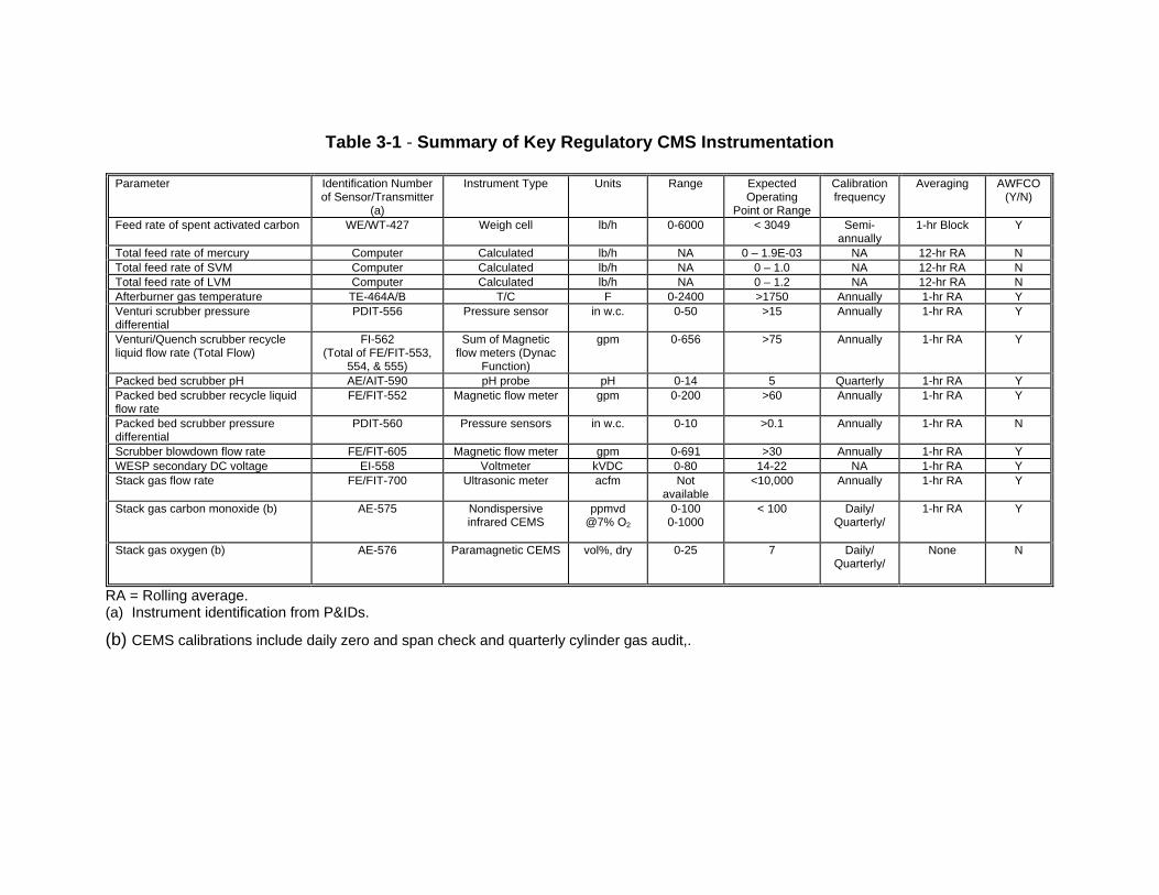
Table 3-1 - Summary of Key Regulatory CMS Instrumentation
Parameter Identification Number of Sensor/Transmitter
(a)
Instrument Type Units Range Expected Operating
Point or Range
Calibration frequency
Averaging AWFCO (Y/N)
Feed rate of spent activated carbon WE/WT-427 Weigh cell lb/h 0-6000 < 3049 Semi-annually
1-hr Block Y
Total feed rate of mercury Computer Calculated lb/h NA 0 – 1.9E-03 NA 12-hr RA N Total feed rate of SVM Computer Calculated lb/h NA 0 – 1.0 NA 12-hr RA N Total feed rate of LVM Computer Calculated lb/h NA 0 – 1.2 NA 12-hr RA N Afterburner gas temperature TE-464A/B T/C F 0-2400 >1750 Annually 1-hr RA Y Venturi scrubber pressure differential
PDIT-556 Pressure sensor in w.c. 0-50 >15 Annually 1-hr RA Y
Venturi/Quench scrubber recycle liquid flow rate (Total Flow)
FI-562 (Total of FE/FIT-553,
554, & 555)
Sum of Magnetic flow meters (Dynac
Function)
gpm 0-656 >75 Annually 1-hr RA Y
Packed bed scrubber pH AE/AIT-590 pH probe pH 0-14 5 Quarterly 1-hr RA Y Packed bed scrubber recycle liquid flow rate
FE/FIT-552 Magnetic flow meter gpm 0-200 >60 Annually 1-hr RA Y
Packed bed scrubber pressure differential
PDIT-560 Pressure sensors in w.c. 0-10 >0.1 Annually 1-hr RA N
Scrubber blowdown flow rate FE/FIT-605 Magnetic flow meter gpm 0-691 >30 Annually 1-hr RA Y WESP secondary DC voltage EI-558 Voltmeter kVDC 0-80 14-22 NA 1-hr RA Y Stack gas flow rate FE/FIT-700 Ultrasonic meter acfm Not
available <10,000 Annually 1-hr RA Y
Stack gas carbon monoxide (b) AE-575 Nondispersive infrared CEMS
ppmvd @7% O2
0-100 0-1000
< 100 Daily/ Quarterly/
1-hr RA Y
Stack gas oxygen (b) AE-576 Paramagnetic CEMS vol%, dry 0-25 7 Daily/ Quarterly/
None N
RA = Rolling average. (a) Instrument identification from P&IDs.
(b) CEMS calibrations include daily zero and span check and quarterly cylinder gas audit,.

Evoqua Water Technologies SSMP
Revision: 0 June 2014
Evoqua Table 3-2 OPLs June 2014.doc Project No. 010111
Table 3-2. Evoqua Operating Parameter Limits
Control Parametersa
Operating Limit
Commentsb
GROUP A1 PARAMETERS Maximum spent carbon feed rate (lb/hr) 3049 Block hour AWFCO Minimum afterburner temperature (oF) 1760 Hourly rolling average AWFCO Minimum hearth #5 temperature (oF) 1350 Hourly rolling average AWFCO Minimum venturi scrubber pressure differential (in. w.c.) 18 Hourly rolling average AWFCO Minimum quench/venturi scrubber total liquid flow rate (gpm)
75 Hourly rolling average AWFCO
Minimum packed bed scrubber pH 4.4 Hourly rolling average AWFCO Minimum packed bed scrubber liquid flow rate (gpm) 63 Hourly rolling average AWFCO Minimum wet scrubber blowdown flow rate (gpm) 58 Hourly rolling average AWFCO Minimum WESP secondary voltage (kVDC) 22 Hourly rolling average AWFCO Maximum stack gas flow rate acfm 9,550 Hourly rolling average AWFCO GROUP A2 PARAMETERS Maximum stack gas carbon monoxide (ppmvd, @7% oxygen)c
100 Hourly rolling average AWFCO
GROUP B PARAMETERS Allowable hazardous constituents All except
dioxin wastes and TSCA PCBs
Class 1 POHC demonstrated
Maximum total chlorine and chloride feed rate (lb/hr) 60 12-hour rolling average Maximum mercury feed rate (lb/hr) 1.8E-03 12-hour rolling average Maximum semivolatile metal (Cd + Pb) feed rate (lb/hr) 1.0E-01 12-hour rolling average Maximum low volatility metal (As + Be + Cr) feed rate (lb/hr)
1.5E+00 12-hour rolling average
GROUP C PARAMETERS Minimum packed bed scrubber pressure differential (in. w.c.)
0.1 Hourly rolling average
(a) Group A1 parameters are continuously monitored and recorded, and are interlocked with the automatic waste feed cutoff
system. The values for the Group A1 parameters are based on the performance demonstration test operating conditions. Group A2 parameters are continuously monitored and recorded, and are interlocked with the automatic waste feed cutoff system. The values for the Group A2 parameters are based on regulatory standards or good operating practice rather than performance demonstration test operating conditions. Group B parameters are continuously monitored and recorded, but are not interlocked with the automatic waste feed cutoff system. Values for the group B parameters are based on the performance demonstration test operating conditions. Group C parameters are continuously monitoring and recording, but are not interlocked with the automatic waste feed cutoff system. The values for the Group C parameters are based on manufacturer’s specifications and/or operational and safety considerations rather than performance demonstration test operating conditions.
(b) AWFCO = Automatic waste feed cutoff. (c) AWFCO interlock will not be active during the daily CEM calibration period.
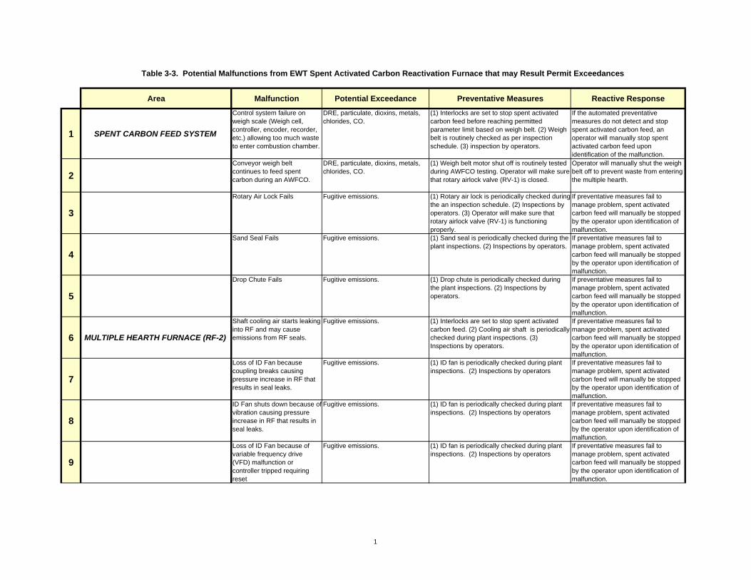
Area Malfunction Potential Exceedance Preventative Measures Reactive Response
1 SPENT CARBON FEED SYSTEM
Control system failure on weigh scale (Weigh cell, controller, encoder, recorder, etc.) allowing too much waste to enter combustion chamber.
DRE, particulate, dioxins, metals, chlorides, CO.
(1) Interlocks are set to stop spent activated carbon feed before reaching permitted parameter limit based on weigh belt. (2) Weigh belt is routinely checked as per inspection schedule. (3) inspection by operators.
If the automated preventative measures do not detect and stop spent activated carbon feed, an operator will manually stop spent activated carbon feed upon identification of the malfunction.
2Conveyor weigh belt continues to feed spent carbon during an AWFCO.
DRE, particulate, dioxins, metals, chlorides, CO.
(1) Weigh belt motor shut off is routinely tested during AWFCO testing. Operator will make sure that rotary airlock valve (RV-1) is closed.
Operator will manually shut the weigh belt off to prevent waste from entering the multiple hearth.
3
Rotary Air Lock Fails Fugitive emissions. (1) Rotary air lock is periodically checked duringthe an inspection schedule. (2) Inspections by operators. (3) Operator will make sure that rotary airlock valve (RV-1) is functioning properly.
If preventative measures fail to manage problem, spent activated carbon feed will manually be stopped by the operator upon identification of malfunction.
4
Sand Seal Fails Fugitive emissions. (1) Sand seal is periodically checked during the plant inspections. (2) Inspections by operators.
If preventative measures fail to manage problem, spent activated carbon feed will manually be stopped by the operator upon identification of malfunction.
5
Drop Chute Fails Fugitive emissions. (1) Drop chute is periodically checked during the plant inspections. (2) Inspections by operators.
If preventative measures fail to manage problem, spent activated carbon feed will manually be stopped by the operator upon identification of malfunction.
6 MULTIPLE HEARTH FURNACE (RF-2)
Shaft cooling air starts leaking into RF and may cause emissions from RF seals.
Fugitive emissions. (1) Interlocks are set to stop spent activated carbon feed. (2) Cooling air shaft is periodically checked during plant inspections. (3) Inspections by operators.
If preventative measures fail to manage problem, spent activated carbon feed will manually be stopped by the operator upon identification of malfunction.
7
Loss of ID Fan because coupling breaks causing pressure increase in RF that results in seal leaks.
Fugitive emissions. (1) ID fan is periodically checked during plant inspections. (2) Inspections by operators
If preventative measures fail to manage problem, spent activated carbon feed will manually be stopped by the operator upon identification of malfunction.
8
ID Fan shuts down because ofvibration causing pressure increase in RF that results in seal leaks.
Fugitive emissions. (1) ID fan is periodically checked during plant inspections. (2) Inspections by operators
If preventative measures fail to manage problem, spent activated carbon feed will manually be stopped by the operator upon identification of malfunction.
9
Loss of ID Fan because of variable frequency drive (VFD) malfunction or controller tripped requiring reset
Fugitive emissions. (1) ID fan is periodically checked during plant inspections. (2) Inspections by operators
If preventative measures fail to manage problem, spent activated carbon feed will manually be stopped by the operator upon identification of malfunction.
Table 3-3. Potential Malfunctions from EWT Spent Activated Carbon Reactivation Furnace that may Result Permit Exceedances
1

Area Malfunction Potential Exceedance Preventative Measures Reactive Response
Table 3-3. Potential Malfunctions from EWT Spent Activated Carbon Reactivation Furnace that may Result Permit Exceedances
10
Loss of ID Fan because of impeller failure
Fugitive emissions. (1) ID fan is periodically checked during the plant outages. (2) Inspections by operators
If preventative measures fail to manage problem, spent activated carbon feed will manually be stopped by the operator upon identification of malfunction.
11
Loss of ID Fan due to moisture buildup in fan housing from condensation.
Fugitive emissions. (1) ID fan is periodically checked during plant inspections. (2) Inspections by operators
If preventative measures fail to manage problem, spent activated carbon feed will manually be stopped by the operator upon identification of malfunction.
12
Draft Sensor plugged up Fugitive emissions. (1) Sensor port periodically checked during plant inspections. (2) Inspections by operators
If preventative measures fail to manage problem, spent activated carbon feed will manually be stopped by the operator upon identification of malfunction.
13
Malfunction of thermocouples in furnace
DRE, dioxins, CO Thermocouple elements are located in the Reactivation Furnace (RF-2). (1) Failure of thermocouples causes burner system to shut down (2) Thermocouples are periodically checked during plant inspections and thermowells are visually inspected during shutdowns. (3) Inspections by operators.
If preventative measures fail to manage the problem, spent activated carbon feed will be manually stopped by the operator after malfunction is identified.
14
Furnace roof arch fails Fugitive emissions. (1) Roof checked inspected during plant outages (2) Inspections by operators and/or maintenance personnel.
If preventative measures fail to manage the problem, spent activated carbon feed will be manually stopped by the operator after malfunction is identified.
15
Furnace hearth door fails. Fugitive emissions. (1) Doors periodically checked during plant outages. (2) Inspections by operators and/or maintenance personnel.
If preventative measures fail to manage the problem, spent activated carbon feed will be manually stopped by the operator after malfunction is identified.
16
Furnace hearth brickwork Fugitive emissions possible. (1) Brickwork periodically checked during plant outages. (2) Inspections by operators and/or maintenance personnel.
If preventative measures fail to manage the problem, spent activated carbon feed will be manually stopped by the operator after malfunction is identified.
17
Furnace Discharge Chute Fails
Fugitive emissions possible. (1) Outlet chute periodically checked during plant outages. (2) Inspections by operators and/or maintenance personnel.
If preventative measures fail to manage the problem, spent activated carbon feed will be manually stopped by the operator after malfunction is identified.
18 AFTERBURNER (AB-2)
Slag buildup on burner in Afterburner causes low Afterburner temperature while spent activated carbon is in the multiple hearth.
DRE, dioxins, CO (1) Interlocks are set to stop spent activated carbon feed before reaching permitted parameter limit and to increase natural gas feed rate to increase temperature. (2) Inspection of burners by operators and/or maintenance personnel.
If preventative measures fail to manage the problem, spent activated carbon feed will be manually stopped by the operator after malfunction is identified.
2
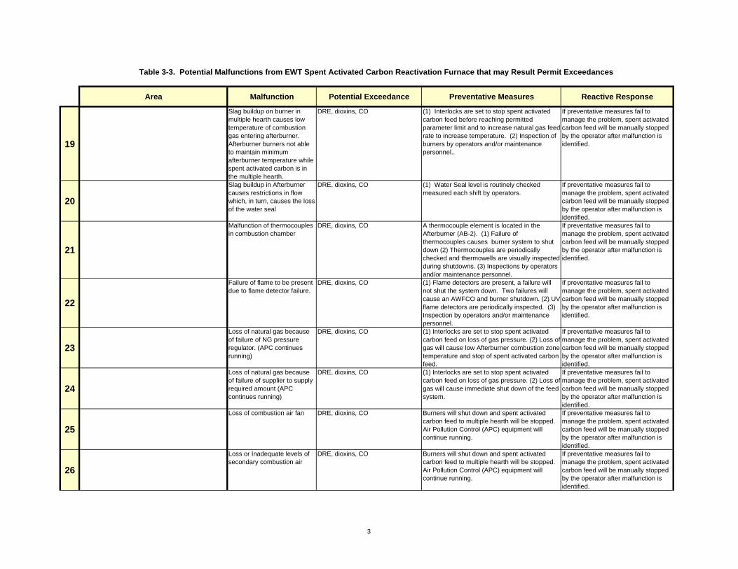
Area Malfunction Potential Exceedance Preventative Measures Reactive Response
Table 3-3. Potential Malfunctions from EWT Spent Activated Carbon Reactivation Furnace that may Result Permit Exceedances
19
Slag buildup on burner in multiple hearth causes low temperature of combustion gas entering afterburner. Afterburner burners not able to maintain minimum afterburner temperature while spent activated carbon is in the multiple hearth.
DRE, dioxins, CO (1) Interlocks are set to stop spent activated carbon feed before reaching permitted parameter limit and to increase natural gas feed rate to increase temperature. (2) Inspection of burners by operators and/or maintenance personnel..
If preventative measures fail to manage the problem, spent activated carbon feed will be manually stopped by the operator after malfunction is identified.
20
Slag buildup in Afterburner causes restrictions in flow which, in turn, causes the loss of the water seal
DRE, dioxins, CO (1) Water Seal level is routinely checked measured each shift by operators.
If preventative measures fail to manage the problem, spent activated carbon feed will be manually stopped by the operator after malfunction is identified.
21
Malfunction of thermocouples in combustion chamber
DRE, dioxins, CO A thermocouple element is located in the Afterburner (AB-2). (1) Failure of thermocouples causes burner system to shut down (2) Thermocouples are periodically checked and thermowells are visually inspected during shutdowns. (3) Inspections by operators and/or maintenance personnel.
If preventative measures fail to manage the problem, spent activated carbon feed will be manually stopped by the operator after malfunction is identified.
22
Failure of flame to be present due to flame detector failure.
DRE, dioxins, CO (1) Flame detectors are present, a failure will not shut the system down. Two failures will cause an AWFCO and burner shutdown. (2) UV flame detectors are periodically inspected. (3) Inspection by operators and/or maintenance personnel.
If preventative measures fail to manage the problem, spent activated carbon feed will be manually stopped by the operator after malfunction is identified.
23
Loss of natural gas because of failure of NG pressure regulator. (APC continues running)
DRE, dioxins, CO (1) Interlocks are set to stop spent activated carbon feed on loss of gas pressure. (2) Loss of gas will cause low Afterburner combustion zone temperature and stop of spent activated carbon feed.
If preventative measures fail to manage the problem, spent activated carbon feed will be manually stopped by the operator after malfunction is identified.
24
Loss of natural gas because of failure of supplier to supply required amount (APC continues running)
DRE, dioxins, CO (1) Interlocks are set to stop spent activated carbon feed on loss of gas pressure. (2) Loss of gas will cause immediate shut down of the feed system.
If preventative measures fail to manage the problem, spent activated carbon feed will be manually stopped by the operator after malfunction is identified.
25
Loss of combustion air fan DRE, dioxins, CO Burners will shut down and spent activated carbon feed to multiple hearth will be stopped. Air Pollution Control (APC) equipment will continue running.
If preventative measures fail to manage the problem, spent activated carbon feed will be manually stopped by the operator after malfunction is identified.
26
Loss or Inadequate levels of secondary combustion air
DRE, dioxins, CO Burners will shut down and spent activated carbon feed to multiple hearth will be stopped. Air Pollution Control (APC) equipment will continue running.
If preventative measures fail to manage the problem, spent activated carbon feed will be manually stopped by the operator after malfunction is identified.
3

Area Malfunction Potential Exceedance Preventative Measures Reactive Response
Table 3-3. Potential Malfunctions from EWT Spent Activated Carbon Reactivation Furnace that may Result Permit Exceedances
27 QUENCH VENTURI SYSTEM (SC-11)
Low Quench/Venturi pressure differential because of failure of DP instrumentation.
Particulate, dioxins, metals, chlorides.
(1) Interlocks are set to stop spent activated carbon feed upon reaching permitted parameter limit. (2) The instruments are on a calibration and inspection schedule. (3) Inspections by operators.
If preventative measures fail to manage the problem, spent activated carbon feed will be manually stopped by the operator after malfunction is identified.
28
Low Quench/Venturi pressure differential because of dampers hung up
Particulate, dioxins, metals, chlorides.
(1) Interlocks are set to stop spent activated carbon feed upon reaching permitted parameter limit. (2) The instruments are on a Preventive Maintenance Program. (3) Inspections by operators.
If preventative measures fail to manage the problem, spent activated carbon feed will be manually stopped by the operator after malfunction is identified.
29
Water Seal Fails Particulate, dioxins, metals, chlorides.
Monitor water seal at least twice per day to determine the level. Low level may be caused by lack of water flow or a restriction in the off-gas system.
If preventative measures fail to manage the problem, spent activated carbon feed will be manually stopped by the operator after malfunction is identified.
30
Pump failure causes low total water flow to Quench/Venturi (temperature out of Q/V does not exceed high-high setting for TSHH-557 and Afterburner burners stay on).
Particulate, dioxins, metals, chlorides.
(1) There are two sources of make-up water. The first is from the city water booster pumps (P17A/B). The second is from the city water supply. (2) Interlocks are set to stop spent activated carbon feed and increase the city water flow upon reaching permitted parameter limit. (3) The instruments are on the routine inspection schedule. (4) If leakage in the waste lines after the flow meters are present, they will be detected during routine walkthroughs of the area.
If preventative measures fail to manage the problem, spent activated carbon feed will be manually stopped by the operator after malfunction is identified.
31
Pump failure causes low total water flow to Quench/Venturi (temperature out of Q/V does exceed high-high setting for TSHH-557 and Afterburner burners shut off).
DRE, particulate, dioxins, metals, chlorides, CO.
(1) There are two sources of make-up water. The first is from the city water booster pumps (P17A/B). The second is from the city water supply. (2) Interlocks are set to stop spent activated carbon feed and increase the city water flow before reaching permitted parameter limit. (3) The instruments are on a calibration and inspection schedule.. (4) If leakage in the waste lines after the flow meters are present, they will be detected during routine walkthroughs of the area.
If preventative measures fail to manage the problem, spent activated carbon feed will be manually stopped by the operator after malfunction is identified.
32
TDS instrument failure causes low Quench/Venturi blowdown rate
Particulate, dioxins, metals, chlorides.
(1) Interlocks are set to stop spent activated carbon feed upon reaching permitted parameter limit. (2) The instruments are on Preventive Maintenance Program. (3) Inspections by operators.
If preventative measures fail to manage the problem, spent activated carbon feed will be manually stopped by the operator after malfunction is identified.
33
Flow control instrument failure causes low Quench/Venturi blowdown rate
Particulate, dioxins, metals, chlorides.
(1) Interlocks are set to stop spent activated carbon feed before reaching permitted parameter limit. (2) The instruments are on calibration and inspection checklist. (3) Inspections by operators.
If preventative measures fail to manage the problem, spent activated carbon feed will be manually stopped by the operator after malfunction is identified.
4

Area Malfunction Potential Exceedance Preventative Measures Reactive Response
Table 3-3. Potential Malfunctions from EWT Spent Activated Carbon Reactivation Furnace that may Result Permit Exceedances
34Pump, impeller, sprays/strainer plugged
Particulate, metals, chlorides. Packing, strainer and impeller will be inspected routinely during selected shutdowns.
Packing will be adjusted (if needed), based on routine inspections during select shutdowns.
35
Motor-pump coupling failure causes loss of pump (P-22) to provide recycle water to Quench/Venturi
Particulate, dioxins, metals, chlorides.
(1) Interlocks are set to stop spent activated carbon feed. (2) When temperature out the Q/V exceeds the High-High limit, the city water will flow to the Q/V. (3) The recycle water pump P-22) is on a inspection schedule. (3) Inspections by operators.
If preventative measures fail to manage the problem, spent activated carbon feed will be manually stopped by the operator after malfunction is identified.
36
Motor failure or overload causes loss of pump (P-22) to provide recycle water to Quench/Venturi
Particulate, dioxins, metals, chlorides.
(1) Interlocks are set to stop spent activated carbon feed. (2) When flowrate is below to the permit limit the feed is stopped. (3) The recycle water pump (P-22) is on a routine inspection schedule. (3) Inspections by operators.
If preventative measures fail to manage the problem, spent activated carbon feed will be manually stopped by the operator after malfunction is identified.
37
Low flow caused by sprays in quench/venturi plugging up
Particulate, dioxins, metals, chlorides.
(1) Interlocks are set to stop spent activated carbon feed. (2) When temperature out the Q/V exceeds the High-High limit, the city water will flow to the Q/V. (3) The recycle water pump P-22) is on a inspection schedule. (3) Inspections by operators.
If preventative measures fail to manage the problem, spent activated carbon feed will be manually stopped by the operator after malfunction is identified.
38
Failure of level control instrument causes low level in PBS Tank shuts down PBS recycle water pump (P-22)
Particulate, metals, chlorides. (1) Low PBS recycle water flow from P-22 initiates interlock to stop spent activated carbon feed. (2) The scrubber water equalization tank (SC-12) level gages are on a inspection checklist. (3) Inspection by operators.
If preventative measures fail to manage the problem, spent activated carbon feed will be manually stopped by the operator after malfunction is identified.
39
Low flow caused by impeller malfunction or plugging.
Particulate, dioxins, metals, chlorides.
(1) Interlocks are set to stop spent activated carbon feed. (2) The recycle water pump (P-22) is on a Preventive Maintenance Program. (3) Inspections by operators.
If preventative measures fail to manage the problem, spent activated carbon feed will be manually stopped by the operator after malfunction is identified.
40
High cross-over temperature due to low quench/venturi flow creating ID fan shutdown
Fugitive emissions. (1) Sprays are periodically checked as part of an inspection schedule (2) Inspections by operators
If preventative measures fail to manage the problem, spent activated carbon feed will be manually stopped by the operator after malfunction is identified.
41 PACKED BED SCRUBBER (SC-12)
Flow control instrument failure causes low total water flow to packed bed scrubber (PBS) (temperature out of PBS does not exceed high-high setting for TSHH-557 and Afterburner burners stay on).
Particulate, metals, chlorides. (1) There are two sources of make-up water. The first is from the city water booster pumps (P17A/B). The second is from the city water supply. (2) Interlocks are set to stop spent activated carbon feed and increase the city water flow before reaching permitted parameter limit. (3) The instruments are on a calibration and inspection checklist. (4) If leakage in the waste lines after the flow meters are present, they will be detected during routine walkthroughs of the area.
If preventative measures fail to manage the problem, spent activated carbon feed will be manually stopped by the operator after malfunction is identified.
5
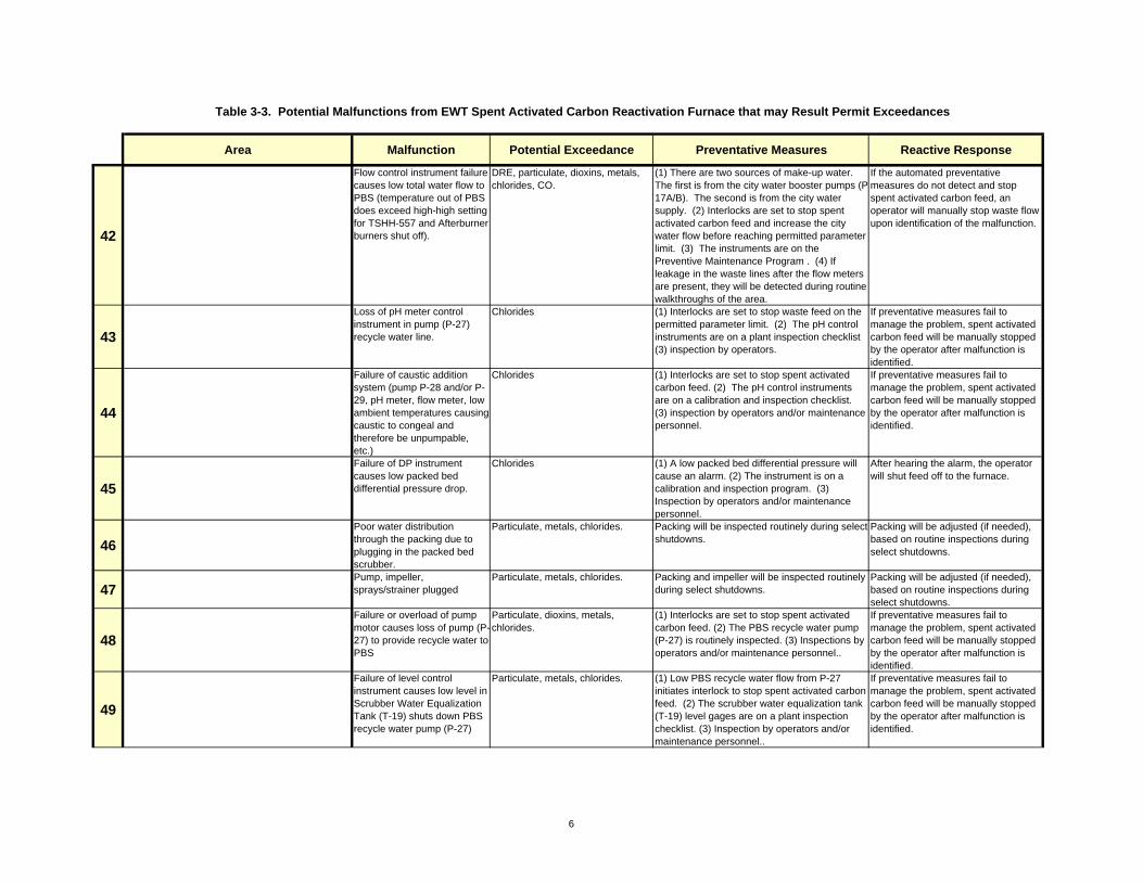
Area Malfunction Potential Exceedance Preventative Measures Reactive Response
Table 3-3. Potential Malfunctions from EWT Spent Activated Carbon Reactivation Furnace that may Result Permit Exceedances
42
Flow control instrument failure causes low total water flow to PBS (temperature out of PBS does exceed high-high setting for TSHH-557 and Afterburner burners shut off).
DRE, particulate, dioxins, metals, chlorides, CO.
(1) There are two sources of make-up water. The first is from the city water booster pumps (P17A/B). The second is from the city water supply. (2) Interlocks are set to stop spent activated carbon feed and increase the city water flow before reaching permitted parameter limit. (3) The instruments are on the Preventive Maintenance Program . (4) If leakage in the waste lines after the flow meters are present, they will be detected during routine walkthroughs of the area.
If the automated preventative measures do not detect and stop spent activated carbon feed, an operator will manually stop waste flow upon identification of the malfunction.
43
Loss of pH meter control instrument in pump (P-27) recycle water line.
Chlorides (1) Interlocks are set to stop waste feed on the permitted parameter limit. (2) The pH control instruments are on a plant inspection checklist (3) inspection by operators.
If preventative measures fail to manage the problem, spent activated carbon feed will be manually stopped by the operator after malfunction is identified.
44
Failure of caustic addition system (pump P-28 and/or P-29, pH meter, flow meter, low ambient temperatures causing caustic to congeal and therefore be unpumpable, etc.)
Chlorides (1) Interlocks are set to stop spent activated carbon feed. (2) The pH control instruments are on a calibration and inspection checklist. (3) inspection by operators and/or maintenance personnel.
If preventative measures fail to manage the problem, spent activated carbon feed will be manually stopped by the operator after malfunction is identified.
45
Failure of DP instrument causes low packed bed differential pressure drop.
Chlorides (1) A low packed bed differential pressure will cause an alarm. (2) The instrument is on a calibration and inspection program. (3) Inspection by operators and/or maintenance personnel.
After hearing the alarm, the operator will shut feed off to the furnace.
46Poor water distribution through the packing due to plugging in the packed bed scrubber.
Particulate, metals, chlorides. Packing will be inspected routinely during select shutdowns.
Packing will be adjusted (if needed), based on routine inspections during select shutdowns.
47Pump, impeller, sprays/strainer plugged
Particulate, metals, chlorides. Packing and impeller will be inspected routinely during select shutdowns.
Packing will be adjusted (if needed), based on routine inspections during select shutdowns.
48
Failure or overload of pump motor causes loss of pump (P-27) to provide recycle water to PBS
Particulate, dioxins, metals, chlorides.
(1) Interlocks are set to stop spent activated carbon feed. (2) The PBS recycle water pump (P-27) is routinely inspected. (3) Inspections by operators and/or maintenance personnel..
If preventative measures fail to manage the problem, spent activated carbon feed will be manually stopped by the operator after malfunction is identified.
49
Failure of level control instrument causes low level in Scrubber Water Equalization Tank (T-19) shuts down PBS recycle water pump (P-27)
Particulate, metals, chlorides. (1) Low PBS recycle water flow from P-27 initiates interlock to stop spent activated carbon feed. (2) The scrubber water equalization tank (T-19) level gages are on a plant inspection checklist. (3) Inspection by operators and/or maintenance personnel..
If preventative measures fail to manage the problem, spent activated carbon feed will be manually stopped by the operator after malfunction is identified.
6
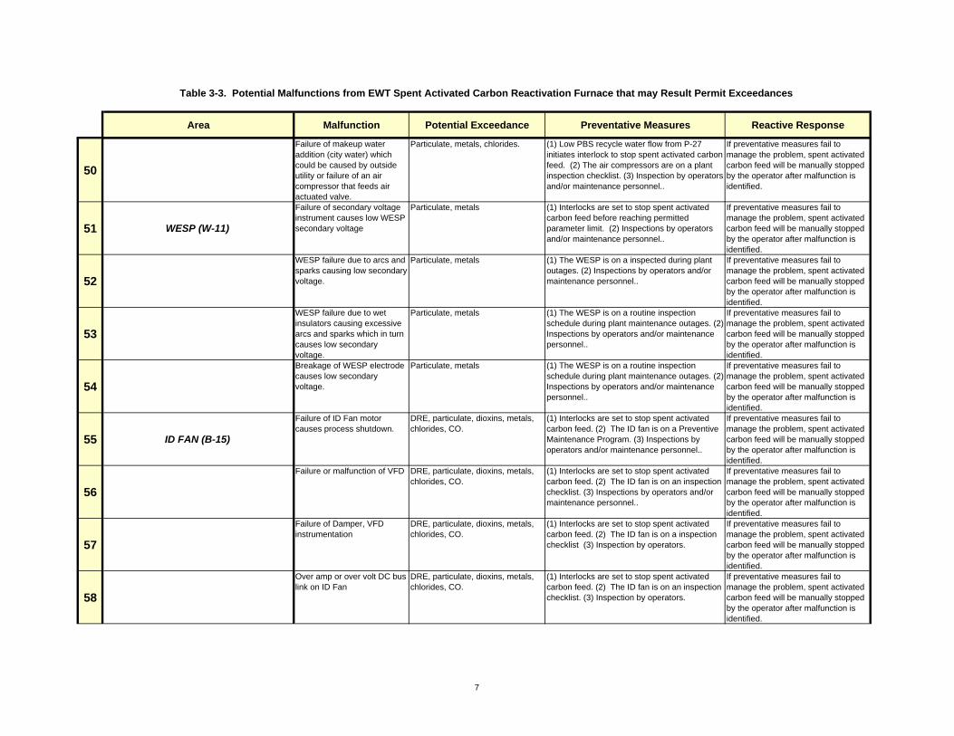
Area Malfunction Potential Exceedance Preventative Measures Reactive Response
Table 3-3. Potential Malfunctions from EWT Spent Activated Carbon Reactivation Furnace that may Result Permit Exceedances
50
Failure of makeup water addition (city water) which could be caused by outside utility or failure of an air compressor that feeds air actuated valve.
Particulate, metals, chlorides. (1) Low PBS recycle water flow from P-27 initiates interlock to stop spent activated carbon feed. (2) The air compressors are on a plant inspection checklist. (3) Inspection by operators and/or maintenance personnel..
If preventative measures fail to manage the problem, spent activated carbon feed will be manually stopped by the operator after malfunction is identified.
51 WESP (W-11)
Failure of secondary voltage instrument causes low WESP secondary voltage
Particulate, metals (1) Interlocks are set to stop spent activated carbon feed before reaching permitted parameter limit. (2) Inspections by operators and/or maintenance personnel..
If preventative measures fail to manage the problem, spent activated carbon feed will be manually stopped by the operator after malfunction is identified.
52
WESP failure due to arcs and sparks causing low secondary voltage.
Particulate, metals (1) The WESP is on a inspected during plant outages. (2) Inspections by operators and/or maintenance personnel..
If preventative measures fail to manage the problem, spent activated carbon feed will be manually stopped by the operator after malfunction is identified.
53
WESP failure due to wet insulators causing excessive arcs and sparks which in turn causes low secondary voltage.
Particulate, metals (1) The WESP is on a routine inspection schedule during plant maintenance outages. (2) Inspections by operators and/or maintenance personnel..
If preventative measures fail to manage the problem, spent activated carbon feed will be manually stopped by the operator after malfunction is identified.
54
Breakage of WESP electrode causes low secondary voltage.
Particulate, metals (1) The WESP is on a routine inspection schedule during plant maintenance outages. (2) Inspections by operators and/or maintenance personnel..
If preventative measures fail to manage the problem, spent activated carbon feed will be manually stopped by the operator after malfunction is identified.
55 ID FAN (B-15)
Failure of ID Fan motor causes process shutdown.
DRE, particulate, dioxins, metals, chlorides, CO.
(1) Interlocks are set to stop spent activated carbon feed. (2) The ID fan is on a Preventive Maintenance Program. (3) Inspections by operators and/or maintenance personnel..
If preventative measures fail to manage the problem, spent activated carbon feed will be manually stopped by the operator after malfunction is identified.
56
Failure or malfunction of VFD DRE, particulate, dioxins, metals, chlorides, CO.
(1) Interlocks are set to stop spent activated carbon feed. (2) The ID fan is on an inspection checklist. (3) Inspections by operators and/or maintenance personnel..
If preventative measures fail to manage the problem, spent activated carbon feed will be manually stopped by the operator after malfunction is identified.
57
Failure of Damper, VFD instrumentation
DRE, particulate, dioxins, metals, chlorides, CO.
(1) Interlocks are set to stop spent activated carbon feed. (2) The ID fan is on a inspection checklist (3) Inspection by operators.
If preventative measures fail to manage the problem, spent activated carbon feed will be manually stopped by the operator after malfunction is identified.
58
Over amp or over volt DC bus link on ID Fan
DRE, particulate, dioxins, metals, chlorides, CO.
(1) Interlocks are set to stop spent activated carbon feed. (2) The ID fan is on an inspection checklist. (3) Inspection by operators.
If preventative measures fail to manage the problem, spent activated carbon feed will be manually stopped by the operator after malfunction is identified.
7

Area Malfunction Potential Exceedance Preventative Measures Reactive Response
Table 3-3. Potential Malfunctions from EWT Spent Activated Carbon Reactivation Furnace that may Result Permit Exceedances
59 STACK
Failure of flow control instrument causes high stack gas flowrate (high combustion gas velocity)
DRE, dioxins, CO. (1) Interlocks are set to stop spent activated carbon feed at the permitted parameter limit. (2) The stack flowmeter is on a calibration and inspection checklist. (3) Inspection by operators and/or maintenance personnel.
If preventative measures fail to manage the problem, spent activated carbon feed will be manually stopped by the operator after malfunction is identified.
60 CEMS STACK MONITORS
Failure of CEMS oxygen monitor
DRE, dioxins, CO (1) Interlocks are set to stop spent activated carbon feed at the permitted parameter limit. (2) The CEMS units are on a calibration and inspection schedule. (3) Inspection by operatorsand/or maintenance personnel.
If preventative measures fail to manage the problem, spent activated carbon feed will be manually stopped by the operator after malfunction is identified.
61 PROGRAMMABLE LOGIC CONTROLLER (PLC)
Failure of electronic component in PLC causes loss of Programmable Logic Controller (PLC) system
DRE, particulate, dioxins, metals, chlorides, CO.
(1) The PLC is inspected by maintenance personnel for proper operation.
Operators will shutdown RF and APC if PLC fails.
62 ALPHA SERVER/WORK STATIONSFailure of Alpha server operator interface
DRE, particulate, dioxins, metals, chlorides, CO.
(1) The Alpha Server is routinely checked for operation regularly. (3) Inspection by maintenance personnel.
Operators will shutdown RF and APC if Server fails.
63 UTILITIES
Failure of air compressor causes loss of instrument air.
DRE, particulate, dioxins, metals, chlorides, CO.
(1) Loss of instrument air will cause interlocks to stop spent activated carbon feed. (2) The instrument air supply equipment is on a (1) The compressors are on a routine inspection schedule (2) Inspections by operators and/or maintenance personnel..
Operators will shutdown RF and APC because of instrument air failure.
64Failure of flow control instrument causes loss of natural gas.
DRE, particulate, dioxins, metals, chlorides, CO.
(1) Loss of natural gas supply will cause interlocks to stop spent activated carbon feed. (2) Inspection by operators.
Operators will shutdown RF and APC because of natural gas failure.
65
Failure of Duplex Pump Controller causes loss of city water booster pumps (P-17A/B).
DRE, particulate, dioxins, metals, chlorides, CO.
(1) Loss of city water will cause interlocks to stop spent activated carbon feed. (2) The city water supply equipment is routinely inspected. (3) Inspection by operators and/or maintenance personnel.
Operators will shutdown RF and APC because of loss of water supply.
66Power Outage caused by trip of Main Breaker (GFI or overload)
DRE, particulate, dioxins, metals, chlorides, CO.
(1) Loss of electrical power will shut the whole plant down immediately.
Operators will shutdown RF and APC because of loss of electrical power.
67Storm or other unforeseen occurrence causes loss of power to facility
DRE, particulate, dioxins, metals, chlorides, CO.
(1) Loss of electrical power will shut the whole plant down immediately.
Operators will shutdown RF and APC because of loss of power .
68Storm or other unforeseen occurrence causes loss of power to facility (City water not available to APC)
DRE, particulate, dioxins, metals, chlorides, CO.
(1) Loss of electrical power will shut the whole plant down immediately.
Operators will shutdown RF and APC because of loss of power .
8

Spiking
Figure 3-1. Carbon Reactivation Furnace System Block Flow Diagram

Spiking
Figure 3-2. Location of Critical Process Instruments
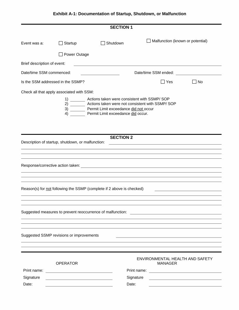
Exhibit A-1: Documentation of Startup, Shutdown, or Malfunction
SECTION 1
Event was a: Startup Shutdown Malfunction (known or potential)
Power Outage
Brief description of event:
Date/time SSM commenced: Date/time SSM ended:
Is the SSM addressed in the SSMP? Yes No
Check all that apply associated with SSM:
1) Actions taken were consistent with SSMP/ SOP 2) Actions taken were not consistent with SSMP/ SOP 3) Permit Limit exceedance did not occur 4) Permit Limit exceedance did occur.
SECTION 2
Description of startup, shutdown, or malfunction:
Response/corrective action taken:
Reason(s) for not following the SSMP (complete if 2 above is checked)
Suggested measures to prevent reoccurrence of malfunction:
Suggested SSMP revisions or improvements
OPERATOR ENVIRONMENTAL HEALTH AND SAFETY
MANAGER
Print name: Print name:
Signature Signature
Date: Date:
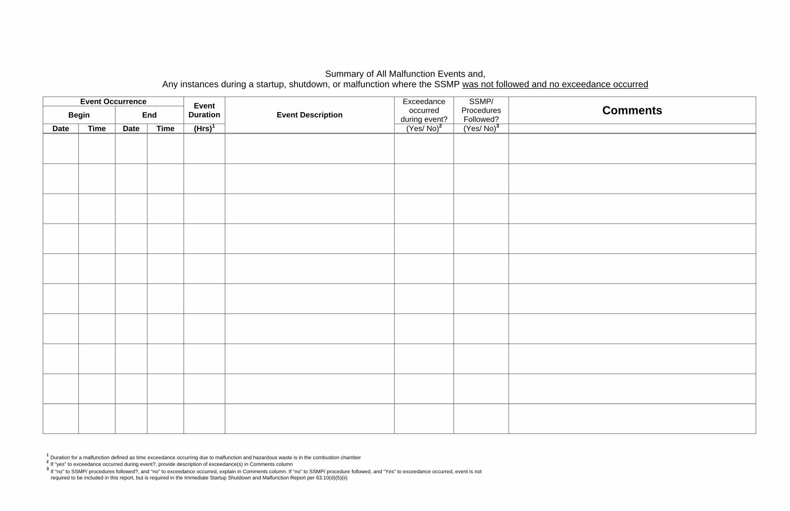
1 Duration for a malfunction defined as time exceedance occurring due to malfunction and hazardous waste is in the combustion chamber 2 If “yes” to exceedance occurred during event?, provide description of exceedance(s) in Comments column 3 If “no” to SSMP/ procedures followed?, and “no” to exceedance occurred, explain in Comments column. If “no” to SSMP/ procedure followed, and “Yes” to exceedance occurred, event is not required to be included in this report, but is required in the Immediate Startup Shutdown and Malfunction Report per 63.10(d)(5)(ii)
Summary of All Malfunction Events and,
Any instances during a startup, shutdown, or malfunction where the SSMP was not followed and no exceedance occurred
Event Occurrence
Begin End Event
Duration Exceedance
occurred during event?
SSMP/ Procedures Followed?
Comments Date Time Date Time (Hrs)1
Event Description
(Yes/ No)2 (Yes/ No)3