evolution of aashto-based bridge design - squarespace · pdf fileevolution of aashto-based...
TRANSCRIPT
Evolution of AASHTO-Based
Bridge Design
Southern Plains Transportation Center
December, 2014
John M. Kulicki, Ph.D., P.E., S.E.
Chairman Emeritus, Modjeski and Masters
Mechanicsburg, Pennsylvania, USA
March, 2013
Topics
• Brief history of the AASHTO Bridge Specs
• How and why of AASHTO LRFD
• Continued evolution to date
• Near term future
• Learning Lesson From Failures
A Brief History of U.S. Bridge
Design Codes
• 1870’s – Bridge Specs start to appear
– Individual engineers
– RR companies
• 1912 – Henry B. Seaman in T.ASCE says special
specs used for each bridge conforming to loads
and span
• 1924 – AASHO Standard Specifications for Steel
Highway Bridges in USDA Bulletin
A Brief History (Continued)
• 1920’s - Special Committee on Specifications
for Bridge Design and Construction
• Wrote “Final Report on Specifications for
Design and Construction of Steel Highway
Bridge Superstructures”
• Presented to ASCE on April 9, 1924
• Partially incorporated into 1St Edition of
AASHO Standard Specifications - 1931
Start of Interstate Era – 1953
AASHTO Standard Specifications
• Impact – as in 1931
• Multiple Presence – 100%, 90%, 75%, never
changed in Std Spec
• GDF – S/5.5 wheel loads
• Traffic Lanes – 12 ft with truck or lane in 10 ft
more or less like now
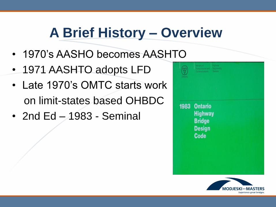
A Brief History – Overview
• 1970’s AASHO becomes AASHTO
• 1971 AASHTO adopts LFD
• Late 1970’s OMTC starts work
on limit-states based OHBDC
• 2nd Ed – 1983 - Seminal
1986 AASHTO Explores Need to
Change
• NCHRP 20-7/31 “Development of
Comprehensive Bridge Specs and Commentary”
• Assess the feasibility of a probability-based
specification.
• Prepare an outline for a revised AASHTO
specification.
May 1987 HSCOBS - A Turning Point
• Findings of NCHRP Project 20-7/31 presented. .
• Funding requested to initiate NCHP Project 12-33
- “Development of Comprehensive Specification
and Commentary”.
• Modjeski and Masters, Inc. began work in July,
1988.
Development Objectives
• Technically state-of-the-art specification.
• Comprehensive as possible.
• Readable and easy to use.
• Keep specification-type wording – do not
develop a textbook.
• Encourage a multi-disciplinary approach to
bridge design.
• Use available past work – no new research
intended
Constraints
• Do not allow for further deterioration.
• Do not explicitly allow future increase in
truck weights.
• No requirement to make bridges uniformly
“heavier” or “lighter”.
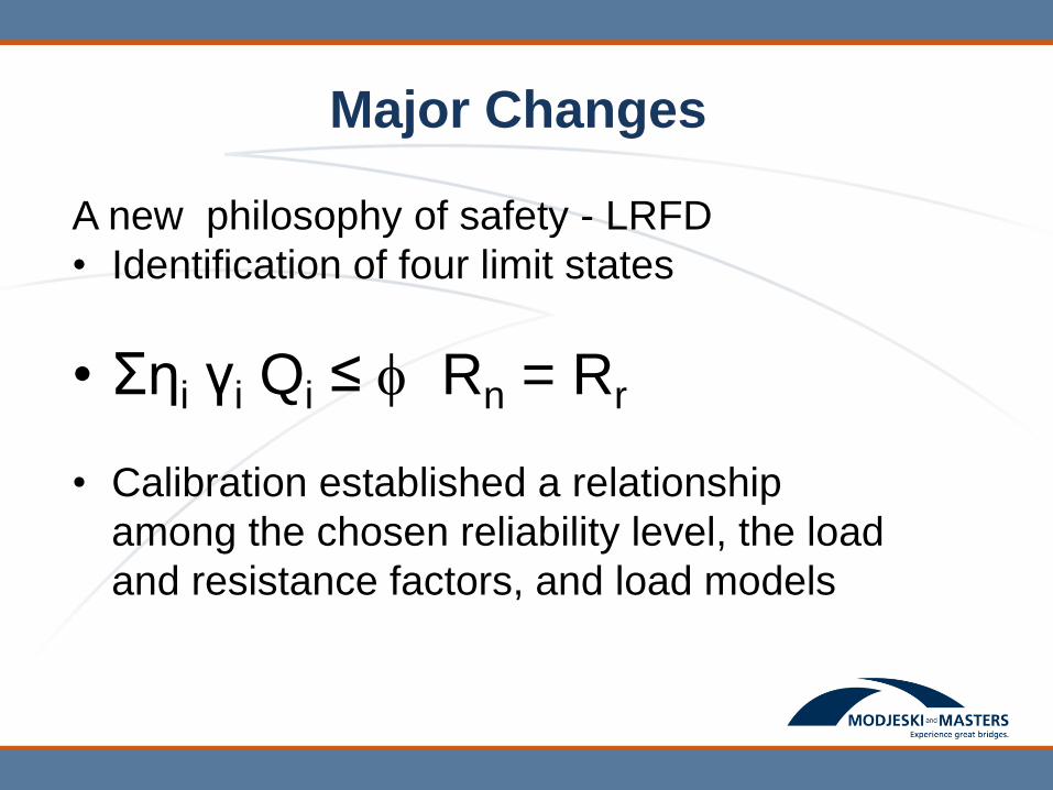
Major Changes
A new philosophy of safety - LRFD
• Identification of four limit states
• Σηi γi Qi ≤ Rn = Rr
• Calibration established a relationship
among the chosen reliability level, the load
and resistance factors, and load models

LRFD - Basic Design Concept
2Q
2R
ii
+ + Q
x =
Lt
K
L
S
2900
S + 0.075 = g
3s
g
0.10.20.6
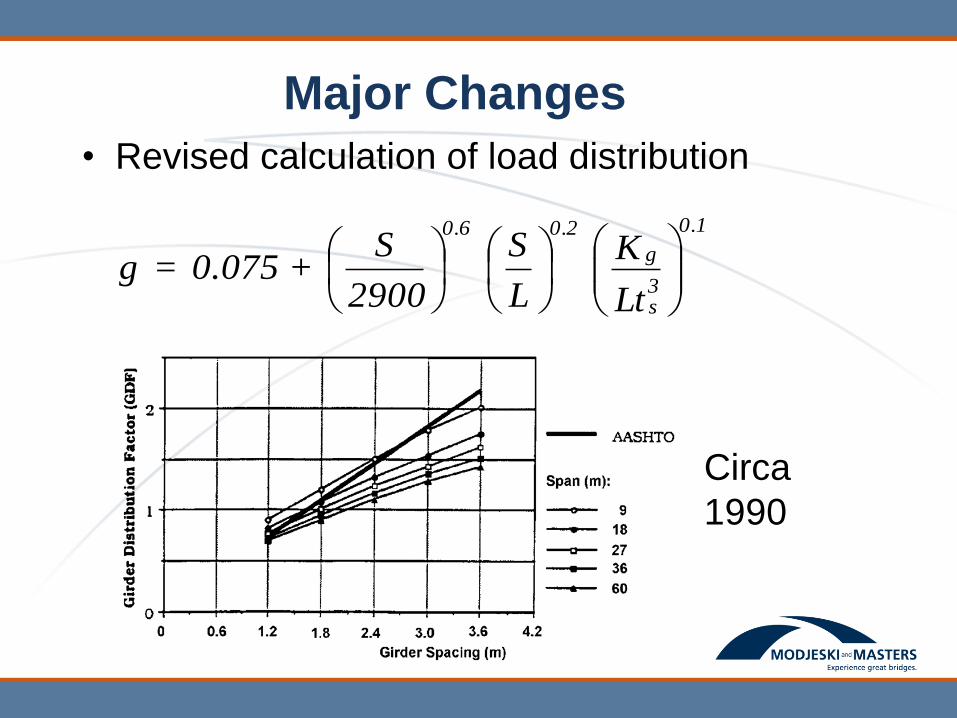
Major Changes
• Revised calculation of load distribution
Circa
1990
Major Changes (Continued)
• Combine plain, reinforced and prestressed
concrete.
• Modified compression field/strut and tie.
• Limit state-based provisions for foundation
design.
• Expanded coverage on hydraulics and scour.
• The introduction of the isotropic deck design.
• Expanded coverage on bridge rails.
• Inclusion of large portions of the AASHTO/FHWA
Specification for ship collision.
Major Changes (Continued)
• Guidance on the design of segmental
concrete bridges – from Guide Specification.
• The development of a parallel commentary.
• New Live Load Model – HL93 - Continuation
of a long story
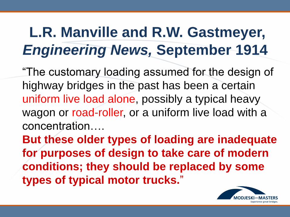
L.R. Manville and R.W. Gastmeyer,
Engineering News, September 1914
“The customary loading assumed for the design of
highway bridges in the past has been a certain
uniform live load alone, possibly a typical heavy
wagon or road-roller, or a uniform live load with a
concentration….
But these older types of loading are inadequate
for purposes of design to take care of modern
conditions; they should be replaced by some
types of typical motor trucks.”
1931 Edition Design Live Load
• 20 ton single unit “box truck” – H20
• H15, H10 for lesser roads
• Truck train for longer spans – groups of H15 with
occasional H20
• Lane load specified for special circumstances –
never updated
• Proportional lane loads for H<20
• Dynamic effect included
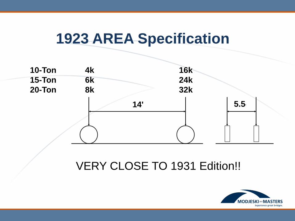
1923 AREA Specification
4k
6k
8k
14'
16k
24k
32k
5.5'
10-Ton
15-Ton
20-Ton
VERY CLOSE TO 1931 Edition!!
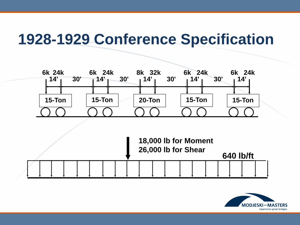
1928-1929 Conference Specification
6k 14' 24k
30' 6k
14' 24k
30' 8k
14' 32k
30' 6k
14' 24k
30' 6k
14' 24k
15-Ton 15-Ton 20-Ton 15-Ton
15-Ton
640 lb/ft
18,000 lb for Moment
26,000 lb for Shear
Design for Live Load is More Than
Just the Truck or Lane Load
• 1931 Edition used:
• Impact – 50/(L+125)
• Traffic Lanes – 9 ft – Crowd but don’t overlap
• Multiple Presence – Function of curb-to-curb
width: Between 18 ft and 43 ft reduce LL by 1%
per ft
• GDF – For 2 or more lanes and S up to 10 ft -
S/5.5, for S>10 ft use lever rule
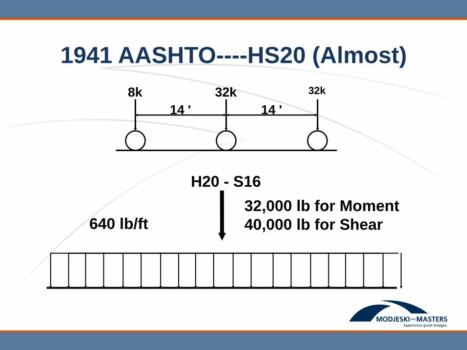
1941 AASHTO----HS20 (Almost)
640 lb/ft 32,000 lb for Moment
40,000 lb for Shear
8k
14 '
32k
14 '
32k
H20 - S16
1944 Agreement
• Much disagreement over HS Loading
• After 3 year study:
• No HS Lane Load---use H20 Lane Load
• Variable axle spacing adopted – more closely
approximates “the tractor trailers now in use”
• HS20-S16-44…..44 added to reduce confusion
from so many changes
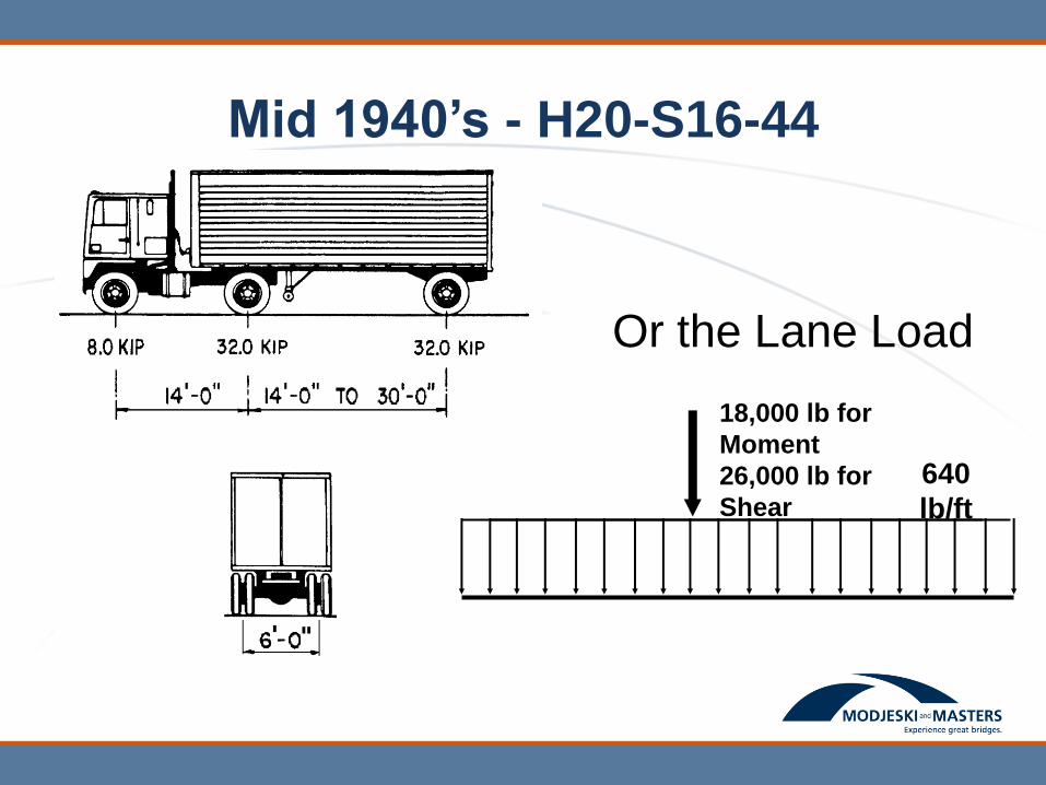
Mid 1940’s - H20-S16-44
Or the Lane Load
640
lb/ft
18,000 lb for
Moment
26,000 lb for
Shear
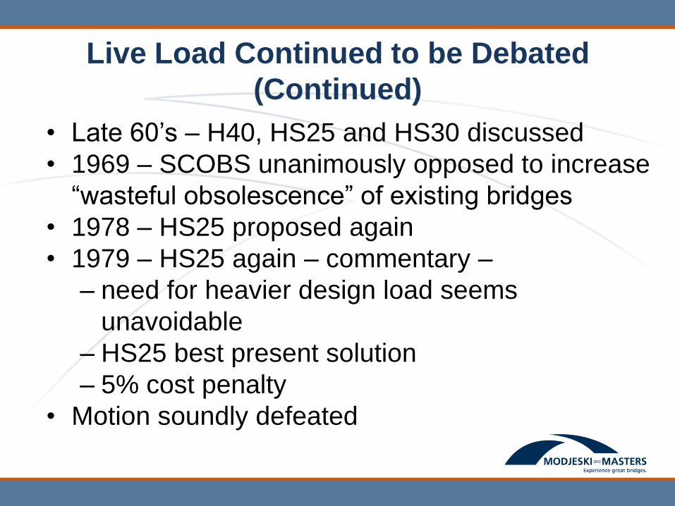
Live Load Continued to be Debated
(Continued)
• Late 60’s – H40, HS25 and HS30 discussed
• 1969 – SCOBS unanimously opposed to increase
“wasteful obsolescence” of existing bridges
• 1978 – HS25 proposed again
• 1979 – HS25 again – commentary –
– need for heavier design load seems
unavoidable
– HS25 best present solution
– 5% cost penalty
• Motion soundly defeated
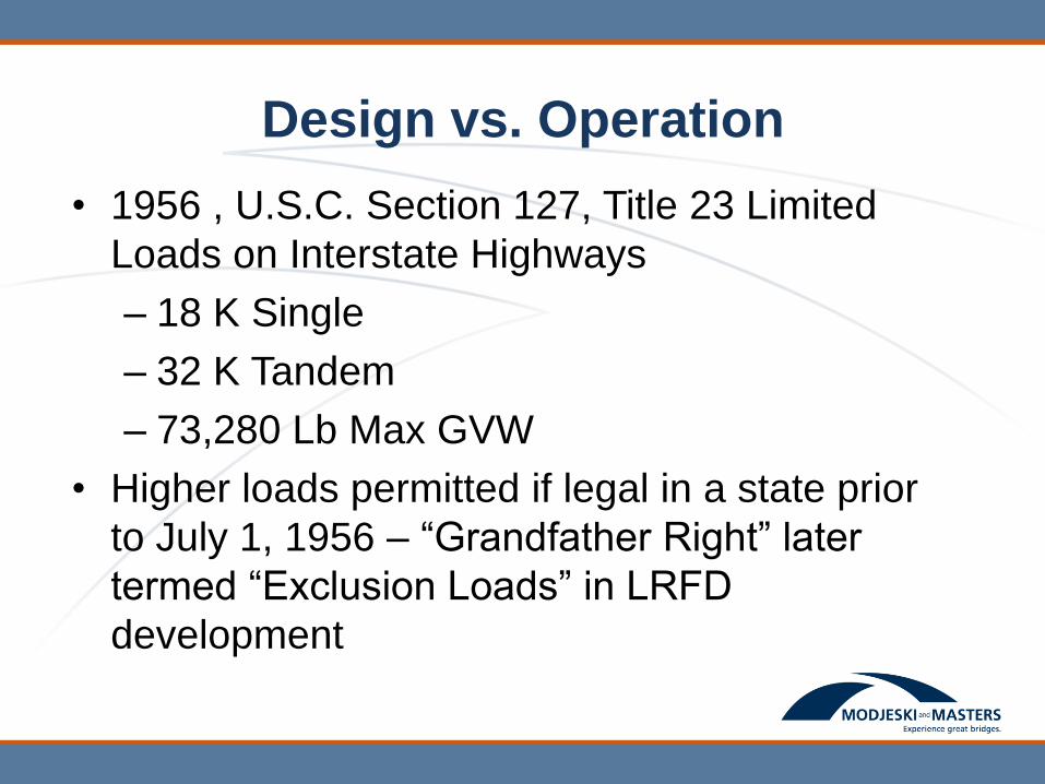
Design vs. Operation
• 1956 , U.S.C. Section 127, Title 23 Limited
Loads on Interstate Highways
– 18 K Single
– 32 K Tandem
– 73,280 Lb Max GVW
• Higher loads permitted if legal in a state prior
to July 1, 1956 – “Grandfather Right” later
termed “Exclusion Loads” in LRFD
development
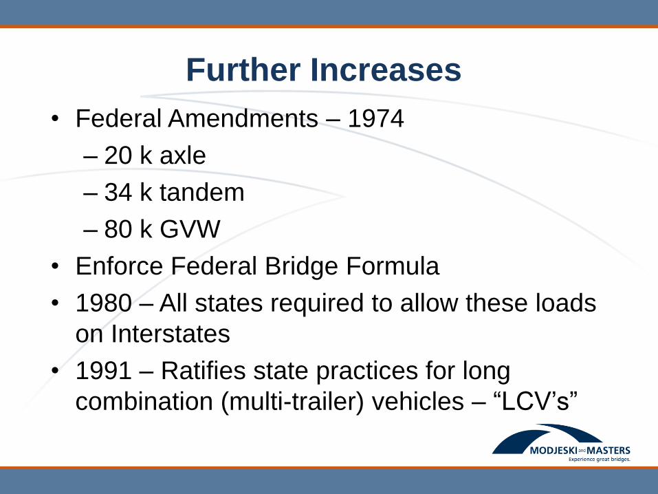
Further Increases
• Federal Amendments – 1974
– 20 k axle
– 34 k tandem
– 80 k GVW
• Enforce Federal Bridge Formula
• 1980 – All states required to allow these loads
on Interstates
• 1991 – Ratifies state practices for long
combination (multi-trailer) vehicles – “LCV’s”

Federal Bridge Formula
where:
W = the maximum weight that can be carried on a
group of two or more axles to the nearest 500
pounds (lb)
L = the spacing between the outer axles of any two or
more axles (ft)
N = the number of axles being considered
Limits HS-15 bridge overstress to about 30%
500 12 36
1
LNW N
N
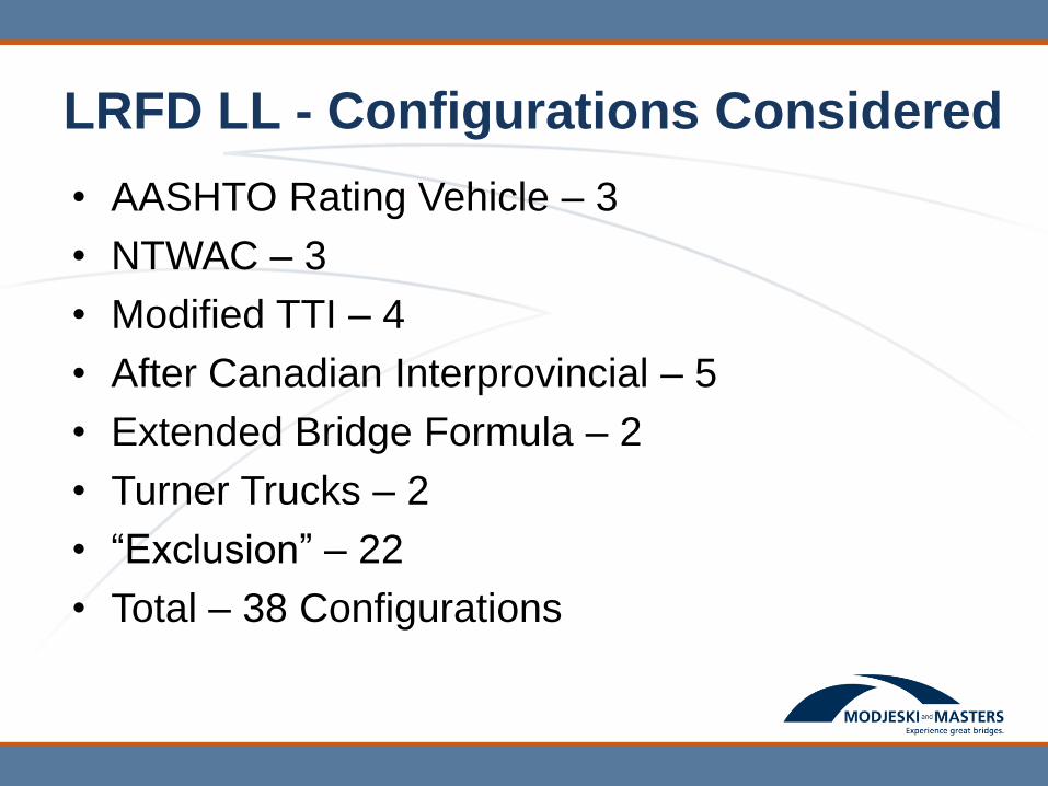
LRFD LL - Configurations Considered
• AASHTO Rating Vehicle – 3
• NTWAC – 3
• Modified TTI – 4
• After Canadian Interprovincial – 5
• Extended Bridge Formula – 2
• Turner Trucks – 2
• “Exclusion” – 22
• Total – 38 Configurations
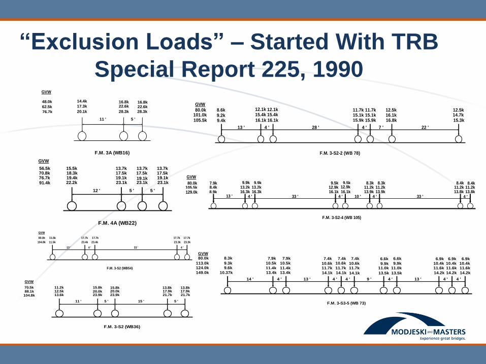
“Exclusion Loads” – Started With TRB
Special Report 225, 1990
20.1k
11 '
28.3k
5 '
28.3k
F.M. 3A (WB16)
17.3k
14.4k
22.6k16.8k 16.8k
22.6k
48.0k
62.5k
76.7k
GVW
22.2k
12 '
23.1k
5 '
23.1k
5 '
23.1k
F.M. 4A (WB22)
19.1k17.5k 17.5k
19.1k
17.5k19.1k19.4k
18.3k15.5k 13.7k 13.7k 13.7k
GVW
56.5k
76.7k70.8k
91.4k
11.5k
13 '
23.4k
4 '
23.4k
33 '
23.3k
4 '
23.3k
F.M. 3-S2 (WB54)
11.5k 17.7k 17.7k 17.7k 17.7k
GVW
104.8k
80.0k
13.6k
11 '
23.9k
5 '
23.9k
15 '
21.7k
5 '
21.7k
F.M. 3-S2 (WB36)
12.5k 20.0k15.8k20.0k 17.9k
13.8k17.9k13.8k11.2k 15.8k70.5k
88.1k104.8k
GVW
9.4k
13 '
16.1k
4 '
16.1k
28 '
15.9k
4 '
15.9k
7 '
16.8k
22 '
15.3k
F.M. 3-S2-2 (WB 78)
9.2k8.6k
15.4k12.1k
15.4k12.1k
15.1k11.7k 11.7k
15.1k 16.1k12.5k
14.7k12.5k
GVW
80.0k101.0k105.5k
8.9k13 '
16.3k4 '
16.3k33 '
16.1k4 '
16.1k10 '
13.9k4 '
13.9k33 '
13.8k4 '13.8k
F.M. 3-S2-4 (WB 105)
8.4k7.9k
13.2k9.9k
13.2k9.9k
12.9k9.5k 9.5k
12.9k 11.2k8.3k 8.3k
11.2k 11.2k8.4k
11.2k8.4k
GVW
80.0k105.5k129.0k
14.2k
6.9k10.4k11.6k
F.M. 3-S3-5 (WB 73)
10.37k
14 '
13.4k
4 '
13.4k
13 '
14.1k
4 '
14.1k
4 '
14.1k
9 '
13.5k
4 '
13.5k
13 '
14.2k
4 '
14.2k
4 '
9.6k9.3k
80.0k
10.5k
11.4k
10.5k
11.4k10.6k11.7k
10.6k
11.7k
8.3k 7.9k 7.9k 7.4k 7.4k 7.4k
10.6k11.7k 11.0k
9.9k
6.6k 6.6k
9.9k11.0k 11.6k
10.4k6.9k 6.9k
10.4k11.6k
GVW
113.0k124.0k
149.0k
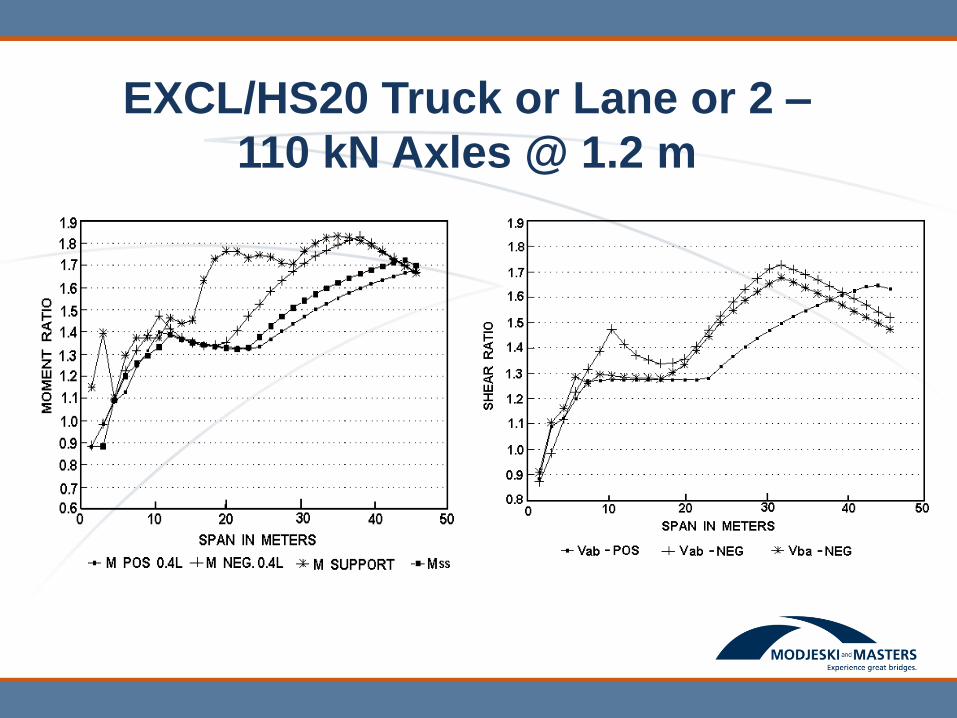
EXCL/HS20 Truck or Lane or 2 –
110 kN Axles @ 1.2 m

Selected Notional Design Load
“HL-93”

EXCL/HL 93 – Moment (Shear Similar)
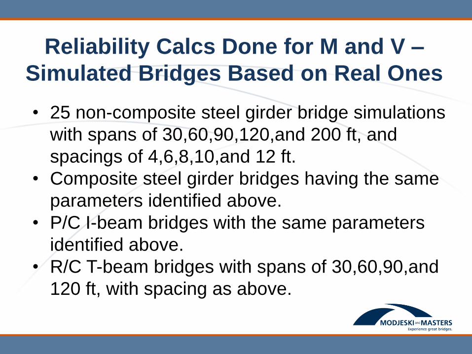
Reliability Calcs Done for M and V –
Simulated Bridges Based on Real Ones
• 25 non-composite steel girder bridge simulations
with spans of 30,60,90,120,and 200 ft, and
spacings of 4,6,8,10,and 12 ft.
• Composite steel girder bridges having the same
parameters identified above.
• P/C I-beam bridges with the same parameters
identified above.
• R/C T-beam bridges with spans of 30,60,90,and
120 ft, with spacing as above.
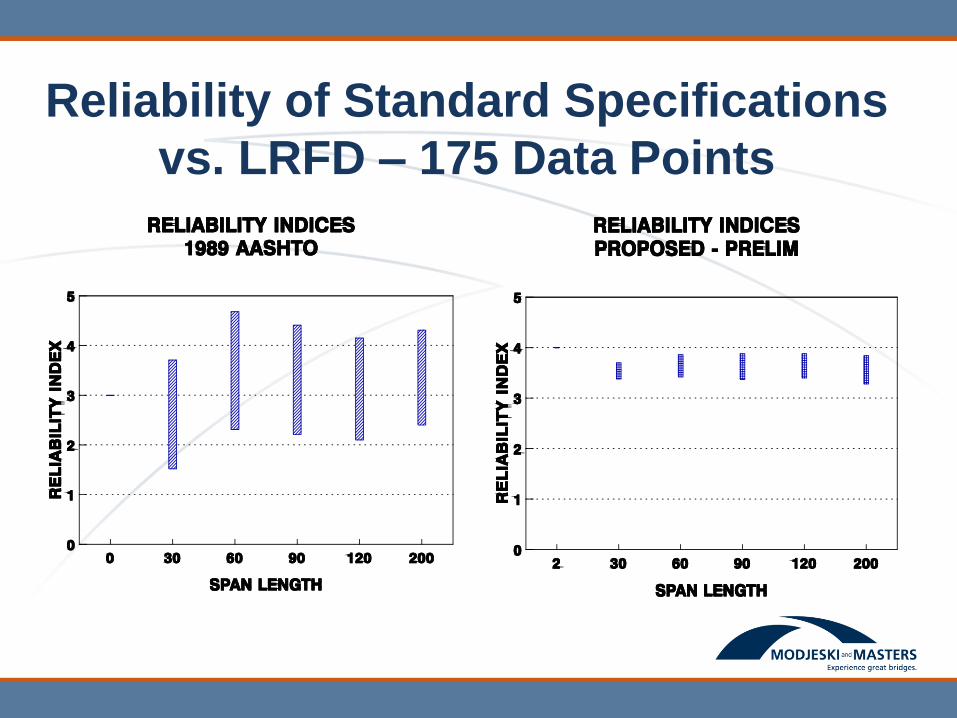
Reliability of Standard Specifications
vs. LRFD – 175 Data Points
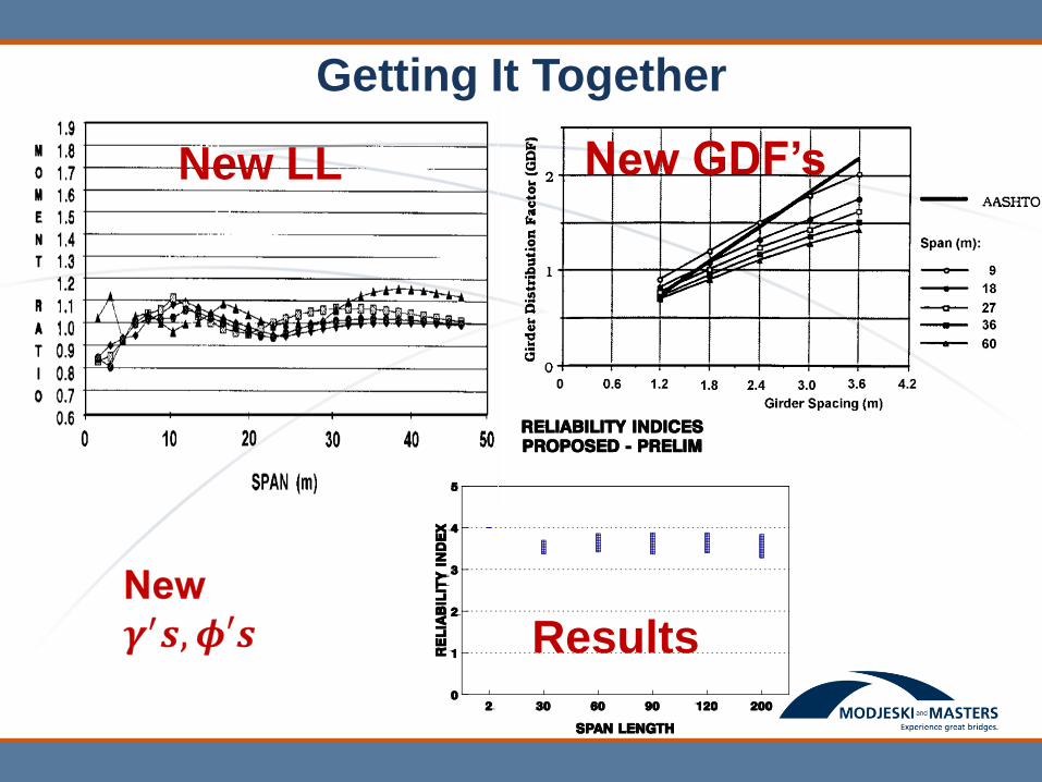
Getting It Together
New LL New GDF’s
Results
Summary of Live Load and
Distribution
• What should you see in designs
– Many designs will be similar, some won’t
– If DF was “improved” the HL 93 will be muted
– If DF unchanged HL 93 can be a big impact
– Exterior often carries more LL
– Shear often proportionately bigger change than
moment
NCHRP 12-33 Project Schedule
• First Draft - 1990 – general coverage
• Second Draft - 1991 – workable
• Third Draft - 1992 – pretty close
• Fourth Draft - 1993 – ADOPTED!!
• 12,000 comments
• Reviewed by hundreds
• Available -1994
• First Major Bridge Opens
In 1997
Evolution and Changes to 1990’s
Technology
• 1996 foundation data reinserted.
• New wall provisions – ongoing upgrade.
• 2002 upgraded to ASBI LFRD Segmental
Guide Specifications.
• MCF shear in concrete simplified and clarified
several times – major updates in 2002 & 2007.
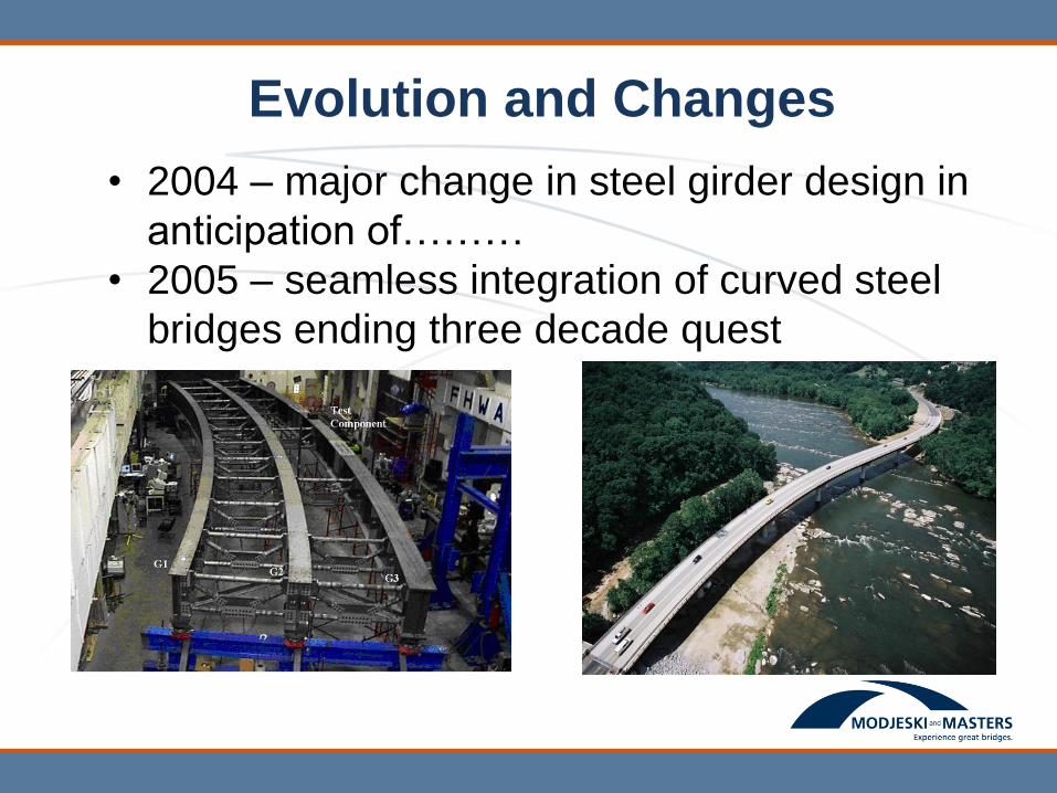
Evolution and Changes
• 2004 – major change in steel girder design in
anticipation of………
• 2005 – seamless integration of curved steel
bridges ending three decade quest
Evolution and Changes (Continued)
• 2005 – P/C loses updated
• 2006 – complete replacement of Section 10 –
Foundation Design
• 2006 – more concrete shear options
• 2007 – big year
– Streamline MCF for concrete shear design
– 1,000 year EQ maps & collateral changes
– Seismic Guide Spec - displacement based
– Pile construction update
• 2008 – Coastal Bridge Guide Specifications
Near Term - Where Do We Go From
Here?
• Calibration of Service Limit State
– Often controls
– Some action possible in 2015
• Quantification of redundancy
• Joint probability or multi-hazard events
– Concurrent or cascading

Learning From Failures and
Mistakes – their Influence on U.S.
Bridge Codes and Practice
First Problem—Defining Failure
• Collapse – event easy to identify and agree on –
cause is something else
• Inability to serve intended function
– Lack of sufficient service strength
– Misalignment
• Unsightly defect
– Cracks
– Misalignment
– Discoloration
• Disproportionate future maintenance
• Shortened service life
How Does Profession React?
• Research
• Additions to design spec to design avoidance
• Changes to material specs
• Changes to fabrication or construction specs
• Add to Non-Spec “body of knowledge”
• Operational changes
• Policy changes
• Retrofits
• Mixtures
Lets look at some examples!!
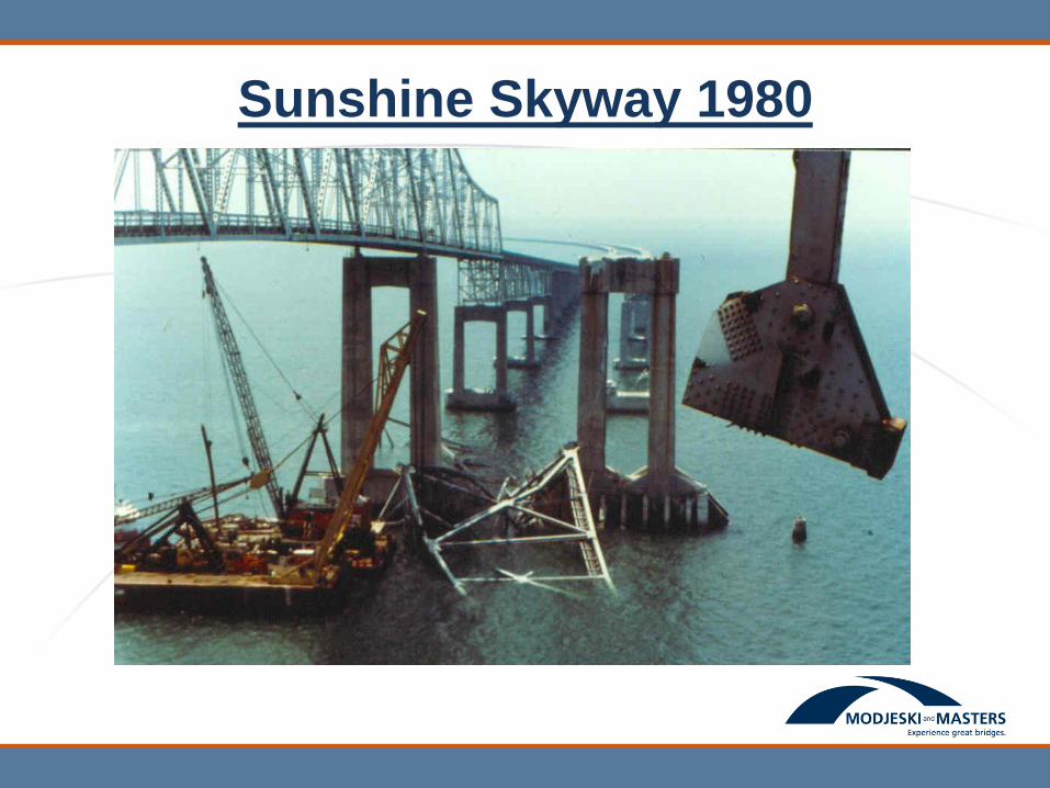
Sunshine Skyway 1980
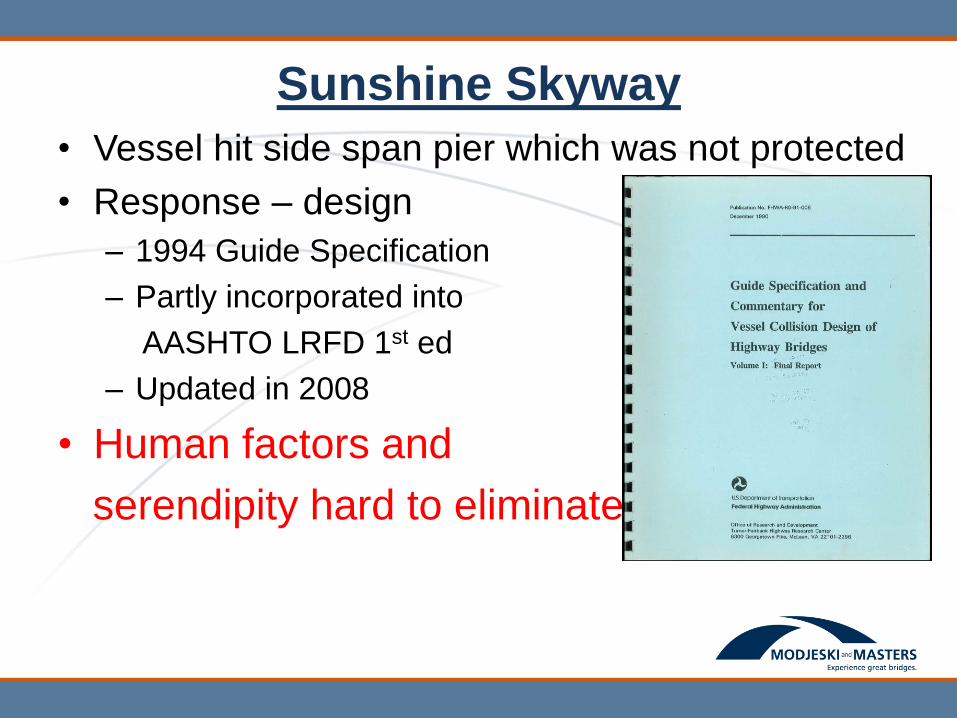
Sunshine Skyway
• Vessel hit side span pier which was not protected
• Response – design
– 1994 Guide Specification
– Partly incorporated into
AASHTO LRFD 1st ed
– Updated in 2008
• Human factors and
serendipity hard to eliminate
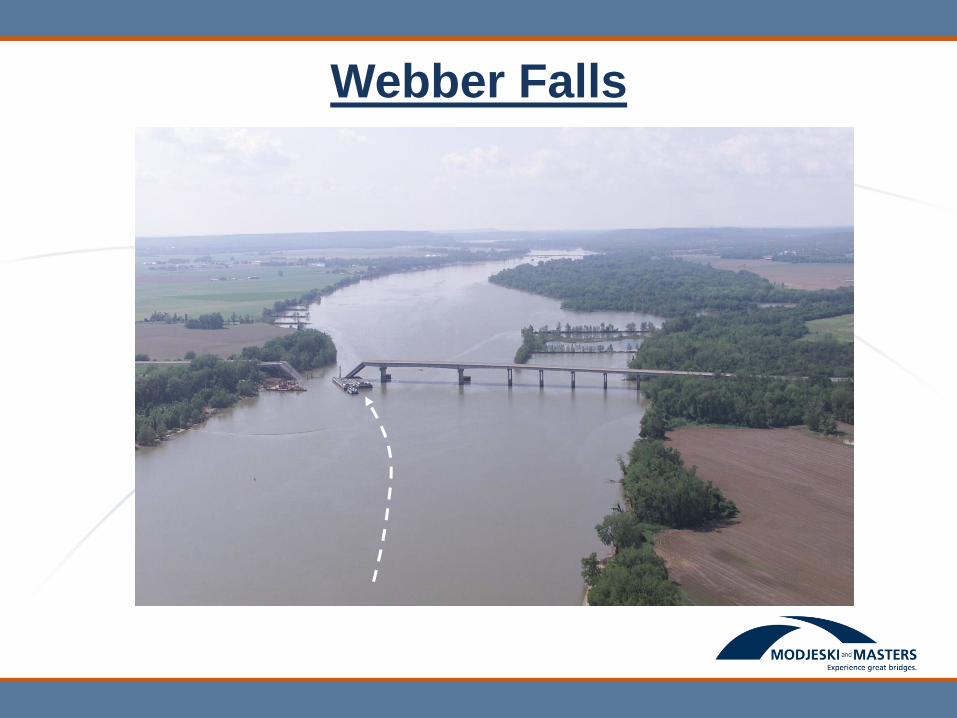
Webber Falls
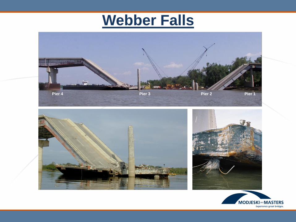
Pier 3 Pier 2 Pier 1 Pier 4
Webber Falls
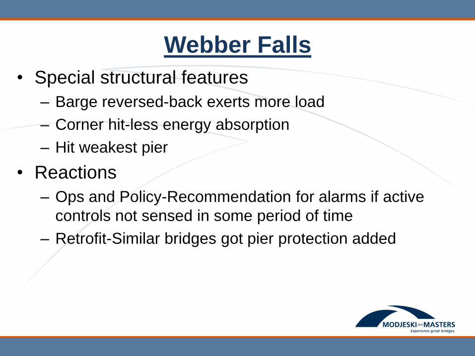
Webber Falls
• Special structural features
– Barge reversed-back exerts more load
– Corner hit-less energy absorption
– Hit weakest pier
• Reactions
– Ops and Policy-Recommendation for alarms if active
controls not sensed in some period of time
– Retrofit-Similar bridges got pier protection added

Webber Falls - Retrofit
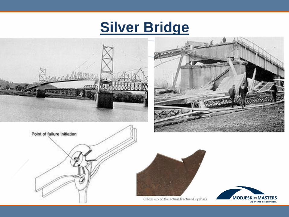
Silver Bridge
Silver Bridge
• Reaction
– Fracture Control plan
• Materials-fracture toughness
• Fabrication-welder quals and testing
• Documentation
• Weld repairs
– Design Specifications
• Identification of FCM and tension components
• Toughness requirements identified but not used in
design calcs
Silver Bridge
• Reaction-cont.
– Policies
• NBIS with special requirements for FCM’s
• Redundancy stressed
• Permit numerical demonstration of redundancy
– Retrofits
• Sister bridge demolished and replaced
• Some redundancy enhancement
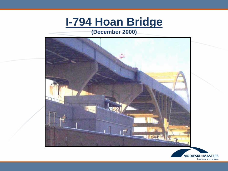
I-794 Hoan Bridge (December 2000)
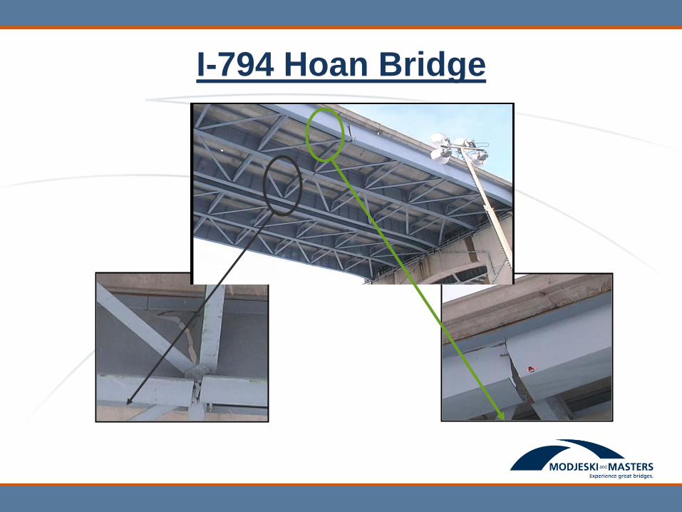
I-794 Hoan Bridge
I-794 Hoan Bridge
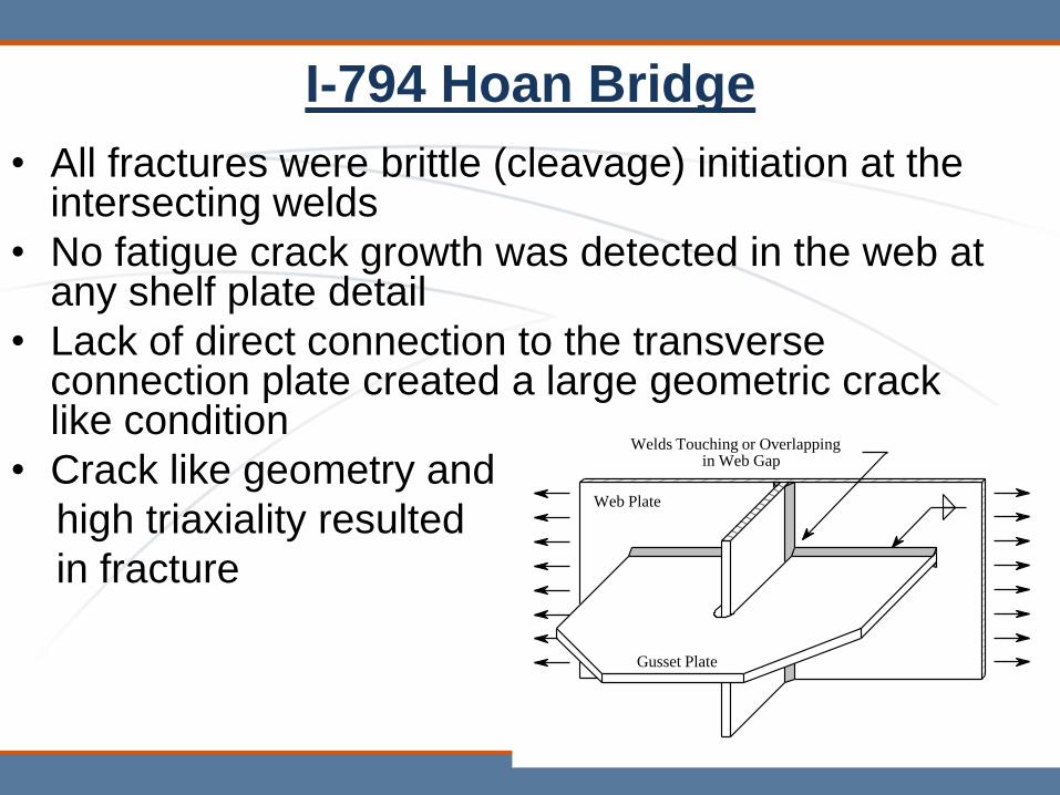
• All fractures were brittle (cleavage) initiation at the intersecting welds
• No fatigue crack growth was detected in the web at any shelf plate detail
• Lack of direct connection to the transverse connection plate created a large geometric crack like condition
• Crack like geometry and
high triaxiality resulted
in fracture
Web Plate
Gusset Plate
Welds Touching or Overlapping in Web Gap
I-794 Hoan Bridge - Response
• FHWA Memorandum cites two criteria that can
indicate fracture vulnerability
– 1) Intersecting / Overlapping welds
– 2) Evidence of rapid crack growth
• Body of Knowledge-Detailing guidance
– ¼” RULE: Intersecting Weld Toes Must
Have at Least ¼” of Clear Separation Toe-to-
Toe to Allow Relief of Constraint
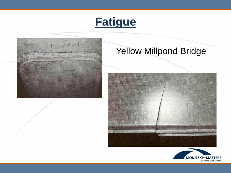
Fatigue
Yellow Millpond Bridge
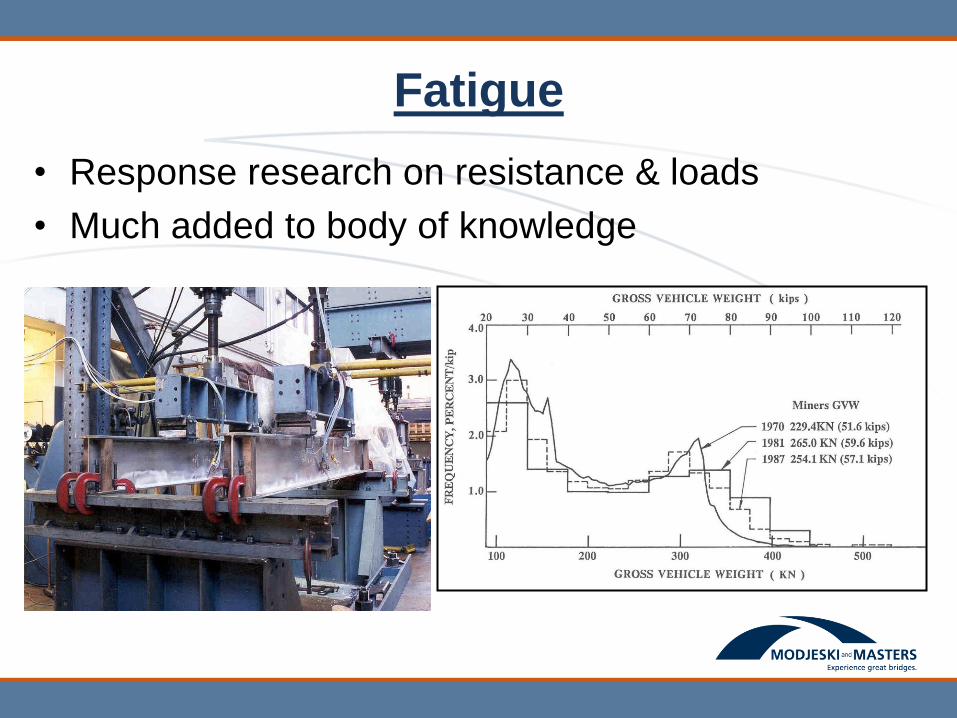
Fatigue
• Response research on resistance & loads
• Much added to body of knowledge
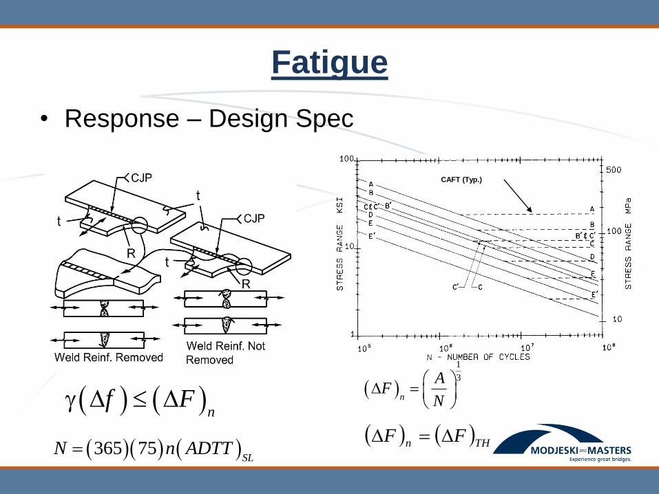
Fatigue
• Response – Design Spec
CAFT (Typ.)
n
f F
365 75SL
N n ADTT
1
3
n
AF
N
THn FF
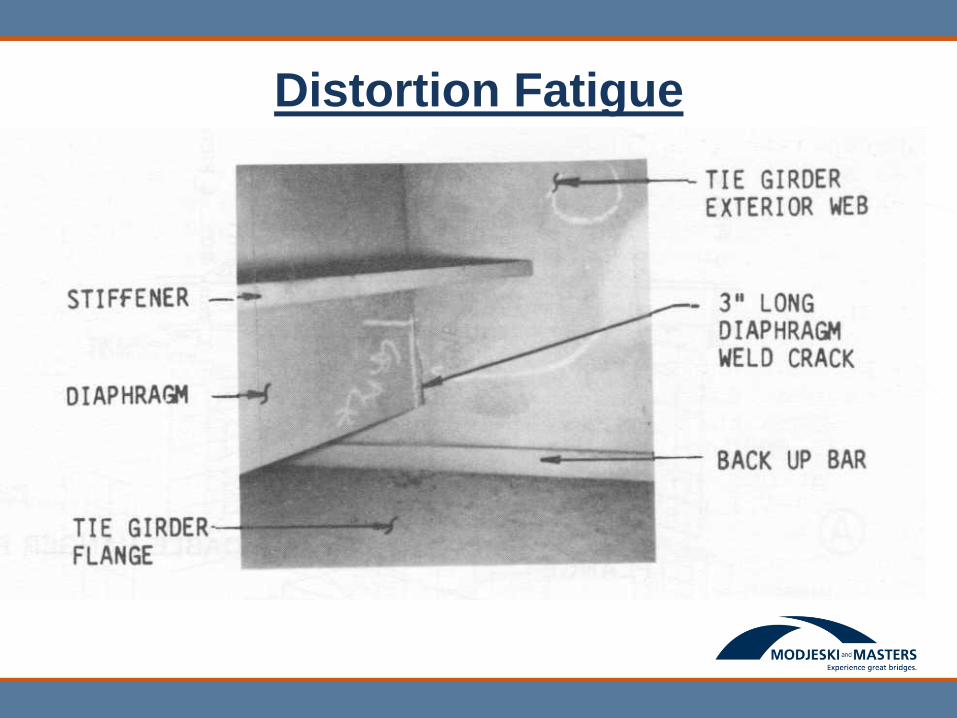
Distortion Fatigue
• Slides coming
Distortion Fatigue
• Response
– Research
– Body of knowledge from case studies
– Specification – verboten details
– No quantification in spec so far
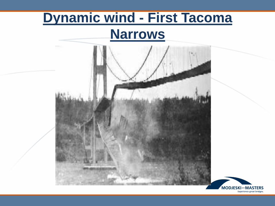
Dynamic wind - First Tacoma
Narrows
Wind - Response
• Research - identify Quasi-static pressure and
understand dynamic phenomena
• Design Spec – “static” wind pressure and
overturning line load
• Body of Knowledge on dynamic actions
– Section models
– Aeroelastic models
– Terrain models
– Computational methods
– A variety of potential fixes
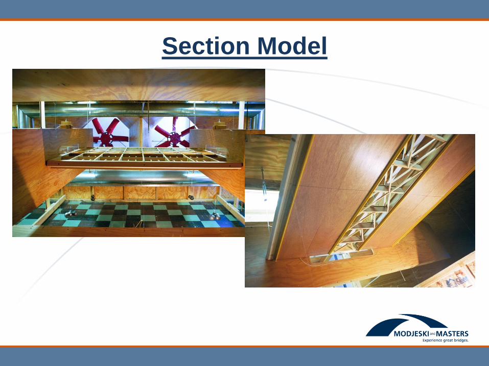
Section Model
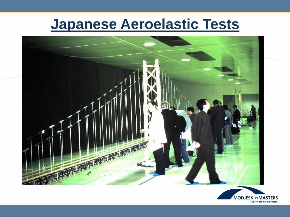
Japanese Aeroelastic Tests

Wind/Rain - Cables
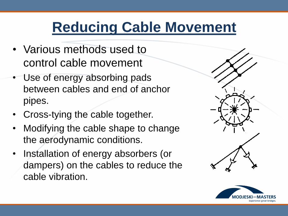
Reducing Cable Movement
• Various methods used to
control cable movement
• Use of energy absorbing pads
between cables and end of anchor
pipes.
• Cross-tying the cable together.
• Modifying the cable shape to change
the aerodynamic conditions.
• Installation of energy absorbers (or
dampers) on the cables to reduce the
cable vibration.
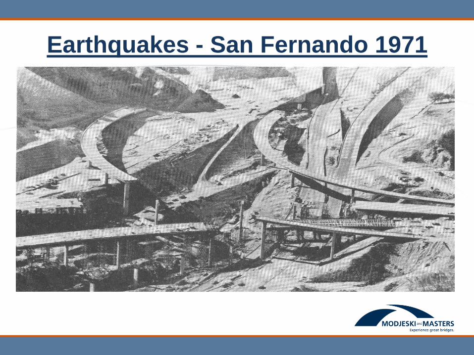
Earthquakes - San Fernando 1971

San Fernando 1971
• Response
– Research-
• Lab tests, particularly on column cyclic behavior
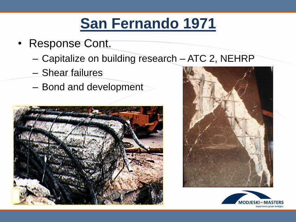
San Fernando 1971
• Response Cont.
– Capitalize on building research – ATC 2, NEHRP
– Shear failures
– Bond and development

San Fernando 1971
• Response Cont
– Design Specifications
• ATC 6 Document lead to
Div. I-A of Std Spec
• SPC
• Design Spectrum
• R factors
• Site factors
2 / 3
1.22.5sm
m
ASC A
T
Site
Coeffi
cient
Soil Profile Type
I II III IV
S 1.0 1.2 1.5 2.0
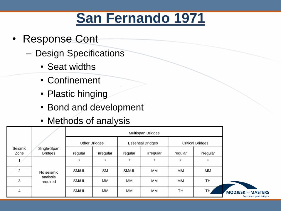
San Fernando 1971
• Response Cont
– Design Specifications
• Seat widths
• Confinement
• Plastic hinging
• Bond and development
• Methods of analysis
Seismic
Zone
Single-Span
Bridges
Multispan Bridges
Other Bridges Essential Bridges Critical Bridges
regular irregular regular irregular regular irregular
1
No seismic
analysis
required
* * * * * *
2 SM/UL SM SM/UL MM MM MM
3 SM/UL MM MM MM MM TH
4 SM/UL MM MM MM TH TH
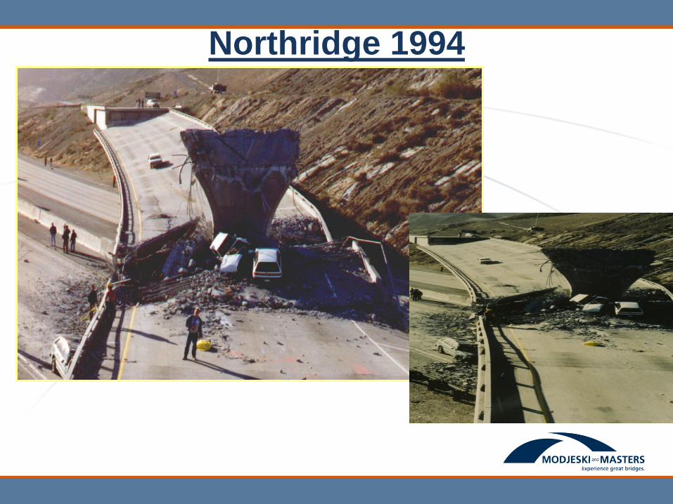
Northridge 1994
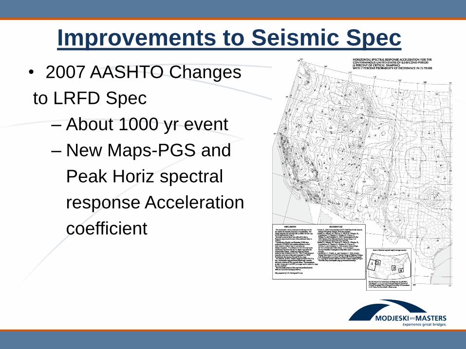
Improvements to Seismic Spec
• 2007 AASHTO Changes
to LRFD Spec
– About 1000 yr event
– New Maps-PGS and
Peak Horiz spectral
response Acceleration
coefficient
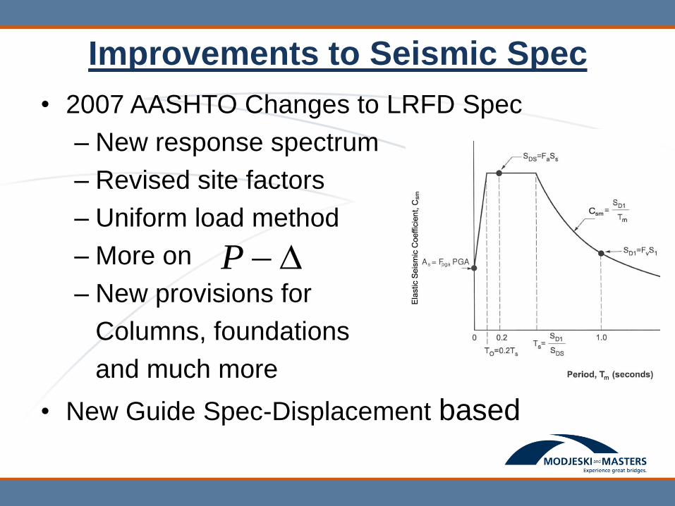
• 2007 AASHTO Changes to LRFD Spec
– New response spectrum
– Revised site factors
– Uniform load method
– More on
– New provisions for
Columns, foundations
and much more
• New Guide Spec-Displacement based
P
Improvements to Seismic Spec
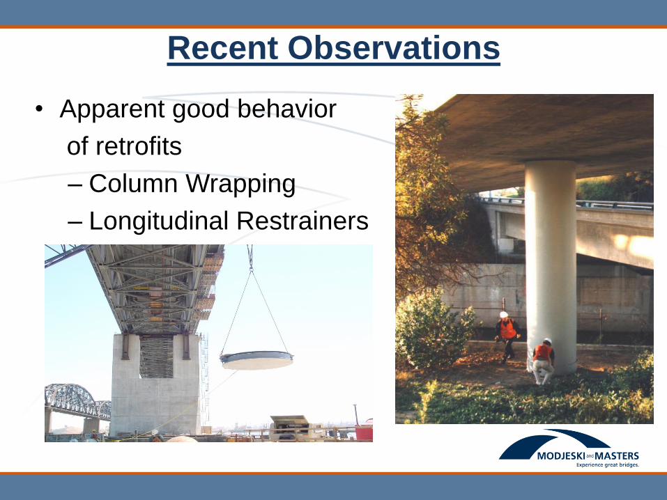
Recent Observations
• Apparent good behavior
of retrofits
– Column Wrapping
– Longitudinal Restrainers
– Isolation

Hurricane Damage
Over $ 2Billion in bridge damage
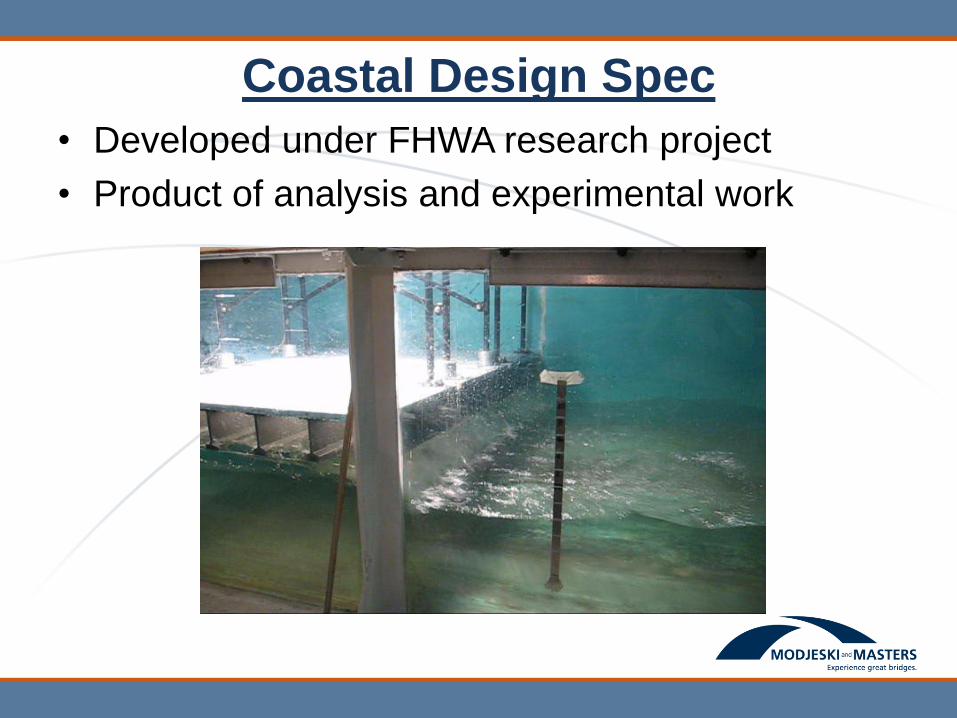
Coastal Design Spec
• Developed under FHWA research project
• Product of analysis and experimental work
Coastal Design Spec
• Empirical design equations based on extensive
simulations using newly developed model of
wave forces
• Adopted in 2008 as a “Guide Specification”
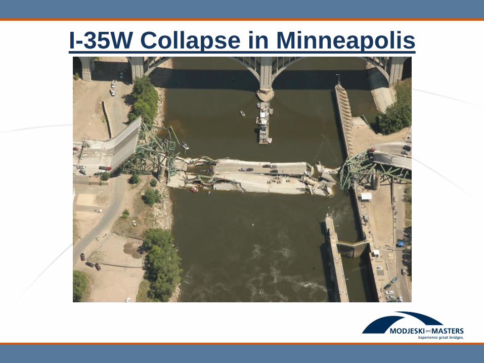
I-35W Collapse in Minneapolis
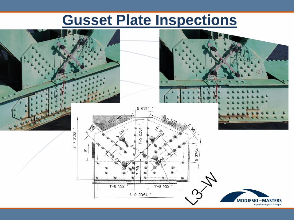
Gusset Plate Inspections
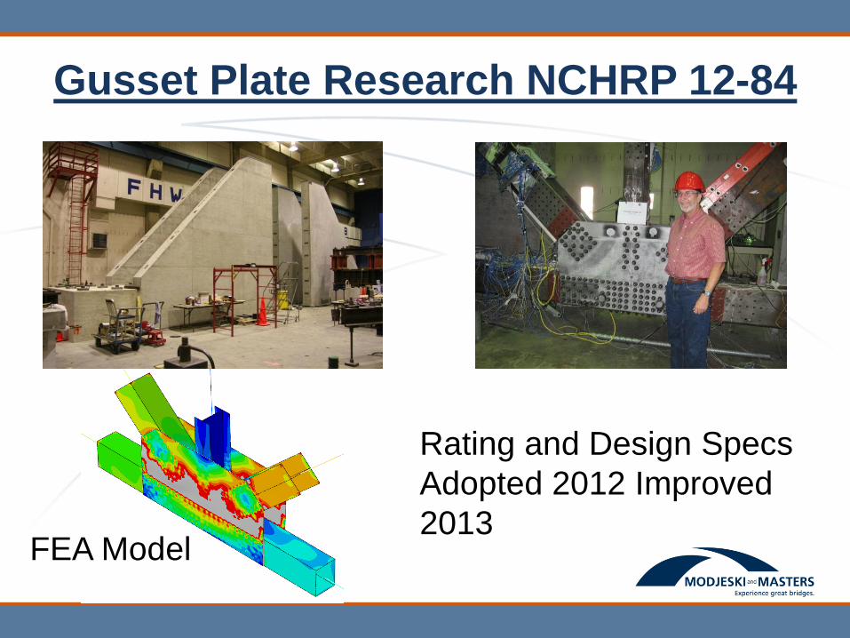
Gusset Plate Research NCHRP 12-84
Rating and Design Specs
Adopted 2012 Improved
2013 FEA Model
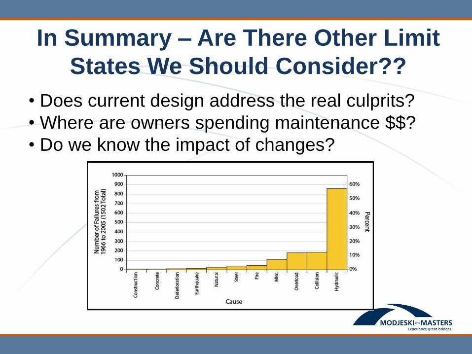
In Summary – Are There Other Limit
States We Should Consider??
• Does current design address the real culprits?
• Where are owners spending maintenance $$?
• Do we know the impact of changes?
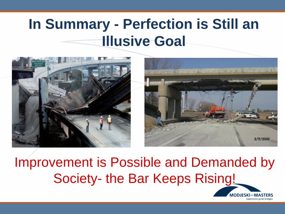
In Summary - Perfection is Still an
Illusive Goal
Improvement is Possible and Demanded by
Society- the Bar Keeps Rising!

Thank you!