evolution and application of the fused silica column
TRANSCRIPT

Evolution and Application of the Fused Silica Column Walter Jennings Department of Food Science and Technology, University of California, Davis, California 9561 6, USA.
Key Words: Fused silica columns Fused silica needles Bondedphases On-column injection
Summary
Fused silica is an evolutionary product of continuing efforts to improveour chromatographic capabilities. It offers thenormal user new horizons in inertness, chromatographic reproducibility, ease of column installation, and possibilities in on-column trap- ping. Since this writing, chemically bonded phases in several film thicknesses became available on fused silica columns, and these are especially well suited to on-column injections. The use of fused silica syringe needles to inject directly onto fused silica columns seems particularly interesting. Evolution is, of course, a continuous process and it would appear that we can expect continuing developments in this exciting area.
Gas chromatography has remained for some years the most widely used analytical technique in the world [ l ] ; it has maintained this status because, as compared to other separation methods, (1) resolution is generally superior, (2) sensitivity is usually good and (3) analysis times are reason- ably short. When they first employed the method, James and Martin [2] used packed columns. A great deal of effort wassubsequently directed toward theselection ofthesolid support, and into studies concerned with techniques for treating and coating that support and packing the column. This endured as the only column form until Golay [3] con- ceived the idea of an open tubular column, which also led to the concept of the SCOT column. While both packed and open-tubular (or capillary) columns continue to be employed, it should be emphasized that except for the adsorptive separations of some fixed gases (e. g., nitrogen, carbon dioxide), only two reasons can be advanced to justify the use of packed columns in analytical (i. e., non- preparative) systems. Both relate to the larger carrier gas flows required by packed columns, which (1) make instru- mental design defects less evident, and (2) render inade- quacies in operator technique less obvious. The price that must be paid for these dubious advantages is (1) less com- plete separation of components, (2) longer analysis times, (3) decreased sensitivities, (4) greater possibilities of com- ponent degradation and abstraction, and (5) higher costs.
Higher costs result not only from the operation of more instruments by more technicians (vide infra), but also in the purchase price of the column itself. Two meters of packed column - which with great good fortune may deliver a grand total of perhaps 10,000 theoretical plates- will cost approximately $50.00. Two meters of the best grade of fused silica capillary will cost, on a prorata basis, about one third as much and will outperform the packed column in every respect except capacity. In spite of this, most chro- matograph manufacturers continue to offer packed column instruments to which capillary optionscan befitted; remarkably few commercial gas chromatographs are designed as capillary instruments that require conversion packages for those individuals who may wish to use packed columns.
The evolutionary process really began when Desty [4] pub- lished the description of an elegantly simple machine for drawing long lengths of glass capillary tubing, which attracted a large number of scientists who began working in this area.The major analytical advantages of gas chromato- graphy - separation, speed and sensitivity - all argue for the use of columns of thevery highest efficiency; there are, of course, very logical arguments that justify this interest in high efficiency columns. To achieve a given separation, the system must possess a certain number of theoretical plates - to take a specific example, 150,000. All other things being equal- column diameter, phase ratio, average linear carrier gas velocity, and based on a test compound with k= 4 to 5- 150,000 theoretical plates can be obtained from a 60 meter column with 50% coating efficiency, a 45 meter column with 75% coating efficiency, or a 30 meter column possessing 100% coating efficiency.* The shorter the column, the shorter the analysis time, and because there has been less time for band broadening to occur, solutes produce peaks that are narrower and higher, resul- ting in greater sensitivity. This gives real gains in two areas: superior analytical results, in terms of better separations in shorter times with higher sensitivities, and in economic fac-
*This approximation is of course valid only at
0 1980 Dr. Alfred Huethig Publishers 0344-71 3818011 20601 -08$01 .OO Journal of HRC & CC 601

Critical Review (The Fused Silica Column)
tors. Shorter analyses times translate to an increased num- ber of analysis per unit time, or to fewer instruments ope- rated by fewer technicians running for shorter periods to deliver the same amount of data.
The major thrust of most of our efforts was therefore in the direction of high efficiency columns.Space restrictions pro- hibit listing the individual contributions that carried ustothe point where a number of highly skilled individuals and at least a few commercial manufacturers were able to pro- duce with reasonable consistency glass capillary columns whose plate numbers approached the theoretical limit.
But then another problem- which we had been uncomfor- tably aware of for some time - began to assume greater importance.This related to the fact that it is not unusual for glass capillary columns to exhibit an activity toward certain specific solutes, which has detrimental effects on both the quantitative and qualitative aspects of the analysis. While it is a simple matter to establish that a given glass open tubu- lar system is more inert than a packed column or metal - including nickle- capillary, inertness is a relative term. We have finally come to realize that there are primarily two things that influence inertness in glass capillary columns: (1) alkali metal oxides and other metal ions such as alumi- num and iron are present in most glass formulations, and where these occur at the glass surface, they can serve as Lewis acid sites, interacting with electron-donor solute molecules; (2) the extralattice valencies of surface silicon atoms that are not involved in crosslinkages normally exhi- bit surface hydroxyl (silanol) groups that can hydrogen bond with susceptible solute molecules.
Several approaches have been used to overcome these problems. One way of dealing with the former is to leach the offending ions from the glass. A great deal of progress on this has been reported by many different workers (e. g., [5- 131). The alternative approach is to use very high purity glass (i.e., fused silica) that contains no metal ions, as explored by Dandeneau and Zerenner [ 141.
This would seem a propitious time to stress that although the two terms are sometimes used interchangeably, there exists a crucial difference between fused quartz and fused silica. The former is produced from naturally occurring deposits that are characterized by a relatively high content of metal ions. Fused silica, on the other hand, is made from a silicon dioxide produced from hydrogen flame decomposi- tion of high purity synthetic silicon tetrachloride, and usual- ly has less than one ppm metal ion contamination.
Certainly some workers can preparevery satisfactory capil- lary columns by leaching conventional glass, but this pro- cess and the subsequent washing and drying operations are time-consuming operations that require a great deal of skill and meticulous attention to detail. Industrial friends tell me that it becomes very difficult to justify the time and effort involved in this type of operation in any environment
except that of a government laboratory or university atmos- phere where labor costs are more or less fixed and gener- ally ignored. (On the other hand, they might be a little sur- prised at how difficult it is becoming to justify some other things in a university atmosphere).
Two methods are most widely used forsilanol deactivation. One, developed largely by Aue [15], the Eindhoven group [16],B/omberg[17],SchomburgeC.a/. [I81 andmanyothers, thermally degrades selected liquid phases under condi- tions where the thermal degradation products can react with the exposed hydroxyl groups. The other widely-used method employs silyation techniquesasexplored by Welch et. a/. [19], Grob et. a/. [20] and by others (e. g. 121-231.
Unfortunately, a very real controversy seems to be brewing among some chromatographic experts over conventional glass versus fused silica. In part this is probably related to the fact that, in contrast to conventional glass capillaries which are drawn at rates of one to two cmlmin in relatively simple machines operating at 600 to 7OO0C, fused silica capillaries are manufactured by an advanced technology using expensive equipment that is not available to the aver- age chromatographer. While the conventional machine can be adapted via high temperature ovens to the ca. 20OO0C required for drawing fused quartz and fused silica [24], most fused silica is drawn under a clean-room atmos- phere using advanced fiber optics technology, including continuous infrared laser monitors that are coupled to micro-processor-controlled feedback control circuitry; remarkably uniform capillaries are drawn at rates of ca. one to two mlsec. Many scientists who have long been involved in manufacturing their own columns of conventional glass suddenly find that they can become involved in this new technology only by purchasing commercial columns or pre- drawn fused silica tubing, which is still relatively expensive. The author suffered the same concerns; for many years I was involved in making, modifying and using capillaries of conventional glass, and the introduction of fused silica columns left me feeling threatened and vulnerable; I also felt very uncomfortable about taking position against fused silica. Even a man so prestigious as the great Liebig, who made so many contributions to our understanding of che- mistry, probably had difficulty later overcoming the fact that he was one of the most vociferous critics of Pasteur’s .efforts to establish a relationship between bacteria and human disease. And there is much food for thought in the fact that contemporaries of van Hoff exposed him to scath- ing ridicule when he first published his concept of the con- figuration of atoms in space. Aftertaking avery critical look at fused silica. I’m one of those that converted.
Let’s explore some of the roots of the controversies. Part of the problem relates to the fact that because the fused silica lattice is not interrupted by other glass formers (Figure l) , it exhibits a high degree of cross-linking. This gives it a much higher softening temperature, approximately 20OO0C as
602 VOL. 3, DECEMBER 1980 Journal of High Resolution Chromatography & Chromatography Communications

Critical Review (The Fused Silica Column)
\ \
/ / -Si -0-H,. -Si -0-H
+ HZO '. /H 15OoC ,:0 \ ,,' \H \
-Si -0-H' -Si--O-H /
0-+@ x SODA-LIME BOROSILICATE
Dehydration reactions of bound silanols. Temperatures are approximate, and may vary slightly with the glass, its history, and the reaction conditions.
LEAD Figure 1
FUSED SILICA
Structures of various glasses. Oxygen atoms are depicted as largeopen circles, silicon atomsassmall dark circles. Adapted from [31].
contrasted with some 600" for conventional glass. It also imparts a much higher tensile strength that permits a very thin-walled capillary, possessing a high degree of flexibility. The thin wall, however, must be protected from even atmospheric corrosion; initially, silicone rubber was used for that purpose. Both polyamides and polyimides are cur- rently used; the former have less thermal resistance and degrade slowly at temperatures of ca. 340°C. Some of the polyimides have much higher thermal stabilities. Even so, a coating with more thermal resistance is certainly desirable. Results recently reported by Pretorius and Desty [25] may offer some hope for a new coating material; even if their optimism proves unfounded, there are so many polymer chemists currently working on this problem, that I cannot believe it will not soon be solved.
The other difference between glass and fused silica is attributable to the higher drawing temperature of the latter. When siliceous glass is exposed to higher temperatures, dehydration of somesurface hydroxyls occurs with the pro- duction of siloxane bridges (Figure 2). The degree of strain in those bridges relates to the interatomic distance of the relevant silicon atoms and determines the propensity of the bridge to undergo subsequent rehydration with regenera- tion of the silanol groups. At still higher temperatures, the lattice atoms can shift within the glass matrix and relieve the strain, so that those bridges become essentially exten- sions of the silicon-oxygen-silicon lattice (Figure 3).
Hydroxyl groups are not necessarily undesirable for our purposes. While they can cause severe activity problems (Figure 4), they can be readily deactivated either by the
Figure 3
165-750. d c-
+
Dehydration reactions producing (top) a strained siloxane bridge that will rehydrate quite readily, and (bottom) a "strain-relieved" bridge that has now become part of the lattice network. Again, temperatures will vary with the glass, its history and the reaction conditions. Portions of this figure were adapted form 1231.
thermal degradation products of selected liquid phases or by high temperature silylation. Silylation reactions have been studied in some detail (e. g., [23]), and it has been clearly established that not all of the silanols undergo reac- tion. The unreacted groups, however, are frequently shield- ed by the umbrella of neighboring groups that did undergo reaction, and are usually less exposed. This reduces their prospects for interaction, not only with the silylating rea- gent, but also with solute molecules, lessening column activity.
Journal of High Resolution Chromatography & Chromatography Communications VOL. 3, DECEMBER 1980 603

Critical Review (The Fused Silica Column)
r -H-.-- ?J-H STRONG ATTRACTION
H
=.H . . Y .. . :+-H WEAK-TO-NO ATTRACTION H
*. : .. . .
STRONG ATTRACTION
Figure 4
Schematic representations of suggested interactions by silanol groups.
Conventional glass surfaces are sometimes subjected to etching processes in order to produce a roughened sur- face, change contact angle relationships and enhance their wettability by a wider variety of liquid phases. Thin-wall fused silica columns become brittle and exhibit excessive fragility when etched, although they too are amenable to a surface roughening that can be induced by the inclusion of micro particulate matter (e. g., [26-281).
The wetting characteristics of the surface can also be affected by the selection of the silylating reagent used to deactivatethesurfacesilanols[17].Butbecauseofthe high temperature parameters involved in its manufacture, fused silica tubing in its virgin state possesses fewer surface hydroxyls than does conventional glass. It is sometimes suggested that it will never be possible to coat polar liquid phases on fused silica. Such statements are unduly pessi- mistic; for one thing, certain leaching processes seem to border on etching procedures, in that some of the lattice bonds are opened. The number of hydroxyl groups on a fused silica surface can be greatly increased by these “leaching” procedures, producing a surface that is fully hydroxylated and that can undergo all of the same reac- tions that are used on conventional glasses. Indeed, chemi- cally bonded phases, which hold great promise for columns
Figure 5
Analysis of acidic phenols on fused silica. Top, column inserted through flame tip to within 2 mm of flame; bottom, column terminatedatbottomofflametip.Notethatthe7cmflametiphas abstracted 2,4-dinitrophenol. Chromatogram from R. R. Freeman [32].
that are completely tolerant of splitless and on-column injection, are an accomplished fact on fused silica columns and will soon be commercially available 1291.
Another major difference between glass and fused silica columns is to be found in the flexibility of the latter, which offers advantages in several areas. For one thing, it elimi- nates the need to flame-straighten and re-deactivate column ends. Because the entire column is inherently straight, the required length of straight column is merely freed from the column cage. Any instrumental configura- tion can be accommodated, and the very thin column wall means that even the wide-bore (0.32 mm) columns have a small O.D. that permits them to be thrust completely through most flame jets so they terminate at the base of the flame itself. Comparison of results achieved with this and more conventional configurations quickly establishes that flame jets themselves may possess strong adsorptive sites (Figure 5). It is also possible to quickly improvise an on- column cold trap by bending a section of the installed column to a U-configuration and immersing that section in a suitablecoolant. Moreelegantly, adeviceofthetypeshown
604 VOL. 3, DECEMBER 1980 Journal of High Resolution Chromatography & Chromatography Communications

Critical Review (The Fused Silica Column)
in Figure 6 can be used for this purpose. Because of this flexibility, the glass or glass-lined stainless steel tubing used in the interface of some GClMS units can often be treated as a guide or conduit, and the fused silica capillary threaded directly through this entire transfer line, unless unusually sharp bends are involved.
Another advantage exhibited by well-deactivated columns is the fact that they exhibit lower bleed rates at elevated temperatures; Carbowax 20M fused silica columns can be used at 220OC. Columns coated with apolar phases such as SE30, SE52 and SE54 will tolerate long-term use at 325OC and behave well at 35OOC. It now seems probable that the column bleed normally associated with high temperature operation is primarily due to volatile sub-molecular frag- ments of the liquid phase, which, in its form as a thin film on an active surface, undergoes degradation at the elevated temperature. The more inactive surface offered by fused silica permits that column to be operated at temperatures more nearly commensurate with the absolute upper tem- perature limit of the liquid phase.
The advantages of being able to program to these higher temperatures are quite straightforward; not only can analy- sis times be shortened appreciably, but also (all other things being constant), because the higher-boiling com- pounds are delivered to the detector at higher tempera- tures, distribution constants are smaller, and peaks are both narrower and higher [30], resulting in increased sensi- tivities.
On a weight basis, fused silica is much more expensive than the conventional glasses and, as we have seen, a more sophisticated technology is employed in the manufacture of the fused silica column. Nevertheless, because of the remarkable uniformity of that surface, the skilled manufac- ture is able to consistently produce a higher percentage of more efficient columns with fused silica than with conven- tional glass. Hence, the fused silica column is competitively priced; currently it is less expensive than a commercial column manufactured from conventional glass.
It is unfortunate that some early papers purporting to com- pare fused silica and conventional glass led to misrepresen- tations of the potentialities of the fused silica column.Some later publications have come a bit closer to the mark, but still leave much to bedesired. In some of these cases, seve- ral variables were changed at the same time, and in other cases, most of the peaks in all chromatograms, including hydrocarbons and internal standards added for quantifica- tion, exhibit a slight degree of tailing which may testify to imperfect connections, reversible adsorption, or a slight porosity of the solid support (column wall). But even if these factors were corrected so that the only variable between the two systems was in fact the nature of the glass in the columns, such comparisons are risky at best. It is possible to make excellent columns out of either material, and to
Figure 6
A thermally-focussed on-column cold trap. The low thermal mass Teflon U tube is connected, via the right and left tees, respectively, to a three way valve outside the oven wall (right side, not shown) and a hot water resevoir above the instrument (lefl side, not shown). Serum caps are used to close the top connection to each tee. The inlet end of the flexible fused silica column is inserted through the serum cap (right side), and pushed through the U tube to emergeon the left side. The other serum cap is fitted, and the column connected to the inlet. With the chromatographoperating, the three-way valve is turned to flood the U-tube with liquid nitrogen from right to left from an affixed reservoir and the injection is made. The valve is then turned to suction, and boiling water is sucked into the U-tube from left to right, and the thermally focussed band begins the chromatographic process. A more elegant method, utilizing a precision-bore glass alignment device to guide a fused silica needle on a standard microliter syringe inside a 0.25 mm fused silica column will soon be reported 1291.
make terrible columns out of either material. Instead of comparing results from small batches of one or the other, it seems more realistic to consider the comments of those hundreds of individual scientists who now have experience of both column types. Earlier, there were some disap- pointing results with fused silica columns; in most cases, these involved small diameter thin-film columns that were too easily overloaded, many of which had been deactivated
Journal of High Resolution Chromatography & Chromatography Communications VOL. 3, DECEMBER 1980 605
Critical Review (The Fused Silica Column)
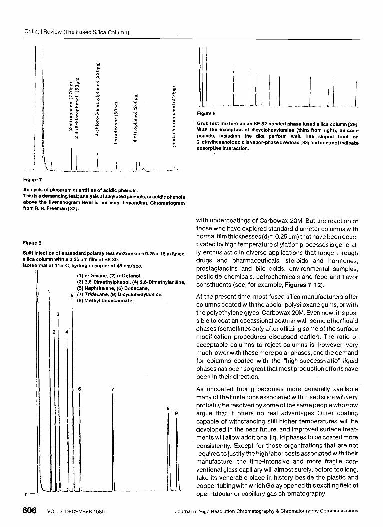
Figure 7
Analysis of picogram quantities of acidic phenols. This is a demanding test; analysisof alkylated phenols, or acidic phenols above the fivenanogram level is not very demanding. Chromatogram from R. R. Freeman [32].
Figure 8
Split injection of a standard polarity test mixture on a 0.25 x 15 m fused silica column with a 0.25 pm film of SE 30. Isothermal at 115OC, hydrogen carrier at 45 cm/sec.
(1) n-Decane, (2) n-Octanol, (3) 2,6-Dimethylphenol, (4) 2,6-Dimethylaniline, (5) Naphthalene, (6) Dodecane,
(9) Methyl Undecanoate. 5 (7) Tridecane, (8) Dicyclohexylamine, 1
r-
3
6 7
1
Figure 9
Grob test mixture on an SE 52 bonded phase fused silica column [29]. With the exception of dicyclohexylamine (third from right), all com- pounds, including the dial perform well. The sloped front on 2-ethylhexanoic acid isvapor-phaseoverload [33] and doesnot indicate adsorptive interaction.
with undercoatings of Carbowax 20M. But the reaction of those who have explored standard diameter columns with normal film thicknesses(df-0.25 pm) that have been deac- tivated by high temperature silylation processes is general- ly enthusiastic in diverse applications that range through drugs and pharmaceuticals, steroids and hormones, prostaglandins and bile acids, environmental samples, pesticide chemicals, petrochemicals and food and flavor constituents (see, for example, Figures 7-12).
A t the present time, most fused silica manufacturers offer columns coated with the apolar polysiloxane gums, or with the polyethylene glycol Carbowax 20M. Even now, it is pos- sible to coat an occassional column with some other liquid phases (sometimes only after utilizing some of the surface modification procedures discussed earlier). The ratio of acceptable columns to reject columns is, however, very much lower with these more polar phases, and the demand for columns coated with the “high-success-ratio’’ liquid phases has been so great that most production efforts have been in their direction.
As uncoated tubing becomes more generally available many of the limitations associated with fused silicawill very probably be resolved by some of the same people who now argue that it offers no real advantages Outer coating capable of withstanding still higher temperatures will be developed in the near future, and improved surface treat- ments will allow additional liquid phases to be coated more consistently. Except for those organizations that are not required to justify the high labor costs associated with their manufacture, the time-intensive and more fragile con- ventional glass capillary will almost surely, before too long, take its venerable place in history beside the plastic and coppertubing with which Golay opened thisexciting field of open-tubular or capillary gas chromatography.
606 VOL. 3, DECEMBER 1980 Journal of High Resolution Chromatography & Chromatography Communications

Critical Review (The Fused Silica Column)
-I
Figure 10
Total ion-current chromatogram from co-injection of EPA base/neutral/ acid compounds on an SE 54 fused silica column. Identifications based on G U M S . By courtesy of Trussell et al. [34].
N-nitrosodimethylamine Phenol Bis (2-chloroethyl) ehter 2-chlorophenol 1,3-DichIorobenzene 1,4-DichIorobenzene I ,2-Dichlorobenzene Bis (2-chloroisopropyl) ether Hexachloroethane N-nitrosodipropylamine Nitrobenzene lsophorone 4-Nitrophenol 2-Nitrophenol 2,CDimethyl phenol Bis (2-chloroethoxy) methane 2,4-Dichlorophenol 1,2,4-Trichlorobenzene Naphthalene Hexachlorobutadiene 2-Chloro-3 methyl phenol Hexachlorocyclopentadiene 2,4,6-Trichlorophenol 2-Chloronaphthalene Acenaphthylene Acenaphthene Dimethyl phthalate 2,4-Dinitrophenol 2-Methyl-4,6-dimethylphenol 2,6-Dinitrotoluene 2,4-Dinitrotoluene Fluorene
c
1
Ju .d, I ,
10 20 40 60 80 Time (rfin.)
4-Chlorophenylphenyl ether Diethyl phthalate N-nitrosodiphenylamine 1,2-Diphenyl hydrazine Hexachlorobenuene Pentachlorophenol Phenanthrene Anthracene Dibutyl phthalate Fluoranthene Pyrene Benzidine
Benzyl butyl phthalate Bis (2-ethyl hexyl) phthalate Chrysene Benzo(a)anthracene 3,3-Dichlorobenzidine Dioctyl phthalate Benro(b)fluoranthene Benzo(k)fluoranthene Benzo(a) pyrene lndeno (1,2,3-~,d)pyrene Dibenzo(a,h)anthracene Benzo(g,h,i)perylene
,p-mnc
- ALDRW
, HEPTACHLOA
1
Figure 11
Total ion-current chromatogram of pesticides on an SE 54 fused silica column. By courtesy of Trussel et al. [34].
Journal of High Resolution Chromatography & chromatography Communications VOL. 3, DECEMBER 1980 607

Critical Review (The Fused Silica Column)
I Figure 12
J - ! Underivatired barbiturates, ca. 10 nglpeak, on a 30 m x 0.25 mm fused silica column, using on-column injection. Components: 1, barbital; 2, amobarbital; 3, secobarbital; 4, hexobarbital; 5, phenobarbital.
References
[l] "The Analytical Instrument Industry 1979," published by Centcom, Ltd., Advertising Management for Am. Chem. SOC. publications (1979) p. 35.
A. T. James and A. J. P. Martin, Biochem J. 50 (1952) 679.
Perkin Elmer Internal Report, authored by M. J. E. Golay, cf. L. S. Ettre in "Glas Capillary Gas Chromatography. The Applica- tions." W. Jennings (ed). Marcel Dekker, Inc. (in press 1981).
[4] D. H. Desty, J. N. Haresnip and B. H. F. Whyman, Anal. Chem, 32 (1 960) 302.
[5] K. Grob, G. Grob and K. Grob Jr., HRC & CC 2 (1979) 31.
[6] K. Grob, G. Grob and K. Grob Jr., HRC & CC 2 (1979) 677.
[7] K. Grob and G. Grob, HRC & CC 3 (1980) 197.
[8] M. Novotny and K. Tesarik, Chromatographia 1 (1968) 332.
[9] G. Schomburg, H. Husmann and F. Weeke, J. Chromatogr. 94 (1 974) 63.
[lo] P. Sandra and M. Verzele, Chromatographia 10 (1977) 419.
[ l l ] G. Alexander and G. Rutten, J. Chromatogr. 6 (1973) 231.
[12] H. Badings, J. VanDerPoland G. Wassink, Chromatographia8 (1 975) 440.
[13] M. L. lee, D. L. Vassilaros, L. V. Phillips, D. M. Hercules, H. Azu- maya, J. W. Jorgensen, M. P. Marharinec and M. Novotny, Anal. Letters 12 (A2) (1979) 191.
[2]
[3]
[14] R. Dandeneau and E. H. Zerenner, HRC & CC 2 (1975) 35.
[15] W A. Aue, C. R. Hastings and S. Kapila, J. Chromatogr. 77
[16] R. C. M. de Nijs, J. J. Franken, R. P. M. Dooper and J. A. Rijks, J.
[17] L. J. Blomberg, J. Chromatogr. 115 (1975) 365.
[18] G. Schomburg, H. Husmann and H. Behlau, Chromatographia
[191 T. Welch, W. Engwald and C. Klaucke, Chromatographia 10
[20] K. Grob, G. Grob and K. Grob Jr., HRC & CC 2 (1 979) 31.
[21] M. Novotny and K. Grohrnann, J. Chromatogr. 84 (1973) 167.
[22] M. Godefroot, M. VanRoelenbosch, M. Verstappe, P. Sandra
(1 973) 299.
Chromatogr. 1967 (1978) 231.
13(1980)321.
(1 977) 22.
and M. Verzele, HRC & CC 3 (1980) 337.
[23] L.Boksanyi,O. Liardonand€.Kovats,Adv.inColloidandInter- face Sci. 6 (1976) 95.
[24] S. R. Lipsky, W. J. McMurray, M. Hernandez, J. E. Purcell and K. A. Billeb, J. Chromatogr. Sci. 18 (1980) 1.
[25l V.Pret0riusandD.H. Desty. Paperpresentedatthe 13thlnter- national Symposium of Chromatography, June 30-July 04, 1980, Cannes.
[26] T. WatanabeandH.Tomita,J.Chromatogr.Sci. 13(1975) 123.
[27] R. C. M. de Nys, G. A. F. M. Rutten, J. J. Franken, R. P. N. Dooper
[28] H. T. Badings, J. J. G. VanDerPoland J. G. Wassink, HRC&CC
[29] R. Jenkins, Personal communication (1980).
[30] W. Jennings, "Gas Chromatography with Glass Capillary Columns," 2nd edition, Academic Press (1980) 130.
[31] J. R. Hutchins, Ill, and R. V. Harrington, Encyclopedia of Chem. Technol. 2nd edition 10 (1966) 533.
[32] R. R. Freeman, paper presented at the North American Con- tinent Chemical Congress Symposium on Advances and the Identification and Analysisof OrganicPollutantsin Water, Las Vegas, Nevada, August 1980. Ann Arbor Science (in press).
[33] K. Yabumoto, D. 1. lngraham and W. Jennings, HRC & CC 3 (1 980) 248.
[34] A. R. Trussell, Fong-Yi Lieu and J. G. Moncur, paper presented at the North American Continent Chemical Congress Symposium on Advances and the Identification and Analysis of Organic Pollutants in Water, Las Vegas, Nevada, August 1980. Ann Arbor Science (in press).
MS received: 1 October 1980
and J. A. Rijks, HRC & CC 2 (1979) 447.
2 (1979) 297.
608 VOL. 3, DECEMBER 1980 Journal of High Resolution Chromatography & Chromatography Communications