every bearing you need head gasket testing special test procedures, field and material related...
TRANSCRIPT

EvEry bEaring you nEEd
Bearings Technical
Manual

[ i ] i n t r o d u c t i o n 4> O e Q u a l i T y T O Ta l c O n f i d e n c e> g ly c O h i s T O r y> fe der al- M o gul r e s e a r c h a n d d e v e l O p M e n T> fe der al- M o gul r a c i n g a c T i v i T i e s> s Tay O n T O p O f T h e l aT e s T d e v e l O p M e n T s
[1] F u n d a m E n ta l s 8> i n s Ta l l aT i O n O f B e a r i n g s> T y p e s O f B e a r i n g s> s T r e n g T h s & w e a k n e s s e s O f e n g i n e B e a r i n g s
[2 ] d E s i g n F E at u r E s o F a s l i d i n g b E a r i n g s h E l l 10> B a s i c M e a s u r e M e n T s & T e r M i n O l O g y> l O c aT i n g l u g> c r u s h h e i g h T> f r e e s p r e a d d i a M e T e r> c r u s h r e l i e f> wa l l T h i c k n e s s> u n d e r s i z e B e a r i n g s
[3 ] b u s h E s & t h r u s t w a s h E r s 14> J O B s> d e s i g n> s T r e s s e s
[4 ] c r a n k p i n s 16> a x i a l s h a p e e r r O r> r a d i a l s h a p e e r r O r> s u r fa c e r O u g h n e s s> n c i c r a n k s h a f T s
[5 ] b E a r i n g c l E a r a n c E 18> fa c T O r s i n f l u e n c i n g B e a r i n g c l e a r a n c e> s i z e a n d T O l e r a n c e s O f B e a r i n g c l e a r a n c e> c O n s e Q u e n c e s O f B e a r i n g c l e a r a n c e f O r T h e e n g i n e> T h e i n f l u e n c e O f O i l T e M p e r aT u r e O n B e a r i n g c l e a r a n c e
[6 ] o i l F i l m 2 0> f u n c T i O n s O f T h e O i l f i l M> l u B r i c aT i n g T h e e n g i n e ’s B e a r i n g s> T h e p h y s i c s O f l u B r i c aT i O n> h y d r O d y n a M i c l u B r i c aT i O n> h y d r O s TaT i c d a M p i n g> d i r T p r O B l e M s
[7 ] m at E r i a l s F o r s l i d i n g b E a r i n g s 2 4> r e Q u i r e M e n T s f O r B e a r i n g M aT e r i a l s> s T r u c T u r e O f B e a r i n g M aT e r i a l s> T y p e s O f B e a r i n g M aT e r i a l s
[8 ] F e d e r a l- m o g u l t E c h n o l o g i E s i n b E a r i n g m at E r i a l s 2 6> g ly c O -19 9 T e c h n O l O g y: g ly c O s p u T T e r B e a r i n g s ®
T h e p r O c e s s r e pa i r & r u n n i n g T i p s g ly c O s p u T T e r B e a r i n g s ®
> l e a d - f r e e B u s h e s & B e a r i n g s n e w l e g i s l aT i O n r e Q u i r e M e n T s l e a d - f r e e M aT e r i a l s g ly c O l e a d - f r e e T e c h n O l O g y: a 3 7 0 ® & c s -4> g ly c O -18 8 T e c h n O l O g y p r i n c i p l e s & a d va n Ta g e s r e s u lT s
c o n c l u s i o n 3 1
TaBle Of
cOnTenTs
g ly c o i s a t r a d e m a r k o f fe d e r a l- M o g u l c o r p o r a t i o n
Bearings
Technical
Manual
nuMBer
Bearings
Chosen by Audi
H079/5 STD Main bearing71-3930/4 STD Conrod bearing
N147/5 STD Small end bush
TECHNOLOGY
Chosen by Mercedes-Benz
H063/4 Main bearing
A150/4 Thrust washer
71-3835 Conrod bearing
56-3839, 56-3840 Camshaft bearing
TECHNOLOGY
4 Bearings Technical Manual
i n t ro d u c t i o n
glycO
hisTOry[ i ]
54 Bearings Technical Manual
Oe QualiT y TOTal cOnfidenceRebuilding an engine requires tremendous skill and hard work. To protect this investment, professional rebuilders rely on the Expert Brands. Federal-Mogul’s industry-leading range of OE-quality replacement engine parts includes not only Glyco® bearings and bushings, but also the globally respected and proven AE® brand of valvetrain, camtrain; belts and related components; Goetze® for piston rings and cylinder liners; the Nüral® brand of pistons and cylinder assembly kits; and Payen® branded gaskets, oil seals and headbolts. This exclusive portfolio of “Expert Brands” provides the OE quality and total confidence preferred by today’s engine rebuilding community.
widesT r angeGlyco is the world’s largest bearing manufacturer with a range of over 2,450 parts, covering more than 5,000 engines. Glyco bearings, established in Germany in 1897, have become a top choice in the industry through a combination of leading technology and product reliability. Our Aftermarket parts are manufactured to the same exact quality specifications as our OE products.Federal-Mogul is a renowned pioneer in the development of advanced materials and designs that help ensure superior engine performance and reliability.
MarkeT leader in TechnOlOgyOur bearings are able to meet extreme demands in terms of withstanding loads and providing long life. The durability of Glyco Sputter Bearings® (Glyco-199) means twice the service life than that of conventional bearings. Glyco G-188 is the first “intelligent” bearing material – soft during the running-in phase, and hard throughout the rest of its life-time. Glyco was also the first to create fully lead-free materials like Glyco A370® and is 100% ready for the EU End of Life Directive (2000/53/EC) – well ahead of its foreseen implementation in 2011.
Oe supplier fOr Over 70 vehicle & engine ManufacTurersGlyco bearings and bushings are engineered in Germany and each year installed as OE components in more than 10 million new automotive, maritime and stationary engines, as well as in agricultural and construction equipment.
Oe QualiT y and TOTal cOnfidence: The ulTiMaTe cOMpeTiTive advanTage avail aBle ThrOugh every engine Br and and prOducT line frOM federal-Mogul.
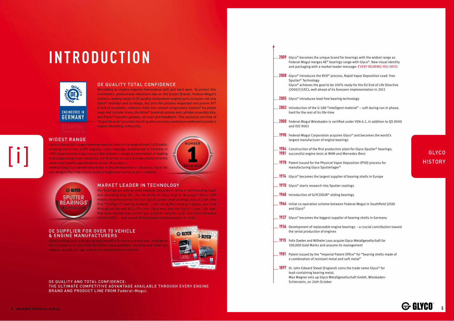
2009 Glyco® becomes the unique brand for bearings with the widest range as Federal-Mogul merges AE® bearings range with Glyco®. New visual identity and packaging with a market leader message: EVERY BEARING YOU NEED
2008 Glyco® introduces the RVD® process, Rapid Vapor Deposition Lead- free Sputter® Technology
Glyco® achieves the goal to be 100% ready for the EU End of Life Directive (2000/53/EC), well ahead of its foreseen implementation in 2011
2005 Glyco® introduces lead-free bearing technology
2003 Introduction of the G-188 “intelligent material” – soft during run-in phase, hard for the rest of its life-time
2000 Federal-Mogul Wiesbaden is certified under VDA 6.1, in addition to QS 9000 and ISO 9001
1990 Federal-Mogul Corporation acquires Glyco® and becomes the world’s largest manufacturer of engine bearings
1984 Construction of the first production plant for Glyco Sputter® bearings;1981 successful engine tests at MAN and Mercedes-Benz
1978 Patent issued for the Physical Vapor Deposition (PVD) process for manufacturing Glyco Sputterlager®
1974 Glyco® becomes the largest supplier of bearing shells in Europe
1970 Glyco® starts research into Sputter coatings
1968 Introduction of GLYCODUR® sliding bearings
1966 Initial co-operation scheme between Federal-Mogul in Southfield (USA) and Glyco®
1937 Glyco® becomes the biggest supplier of bearing shells in Germany
1936 Development of replaceable engine bearings – a crucial contribution toward the serial production of engines
1915 Felix Daelen and Wilhelm Loos acquire Glyco-Metallgesellschaft for 100,000 Gold Marks and assume its management
1901 Patent issued by the “Imperial Patent Office” for “bearing shells made of a combination of resistant metal and soft metal”
1897 Dr. John Edward Stead (England) coins the trade name Glyco® for lead-containing bearing metal.
Max Wagner sets up Glyco Metallgesellschaft GmbH, Wiesbaden- Schierstein, on 24th October
76 Bearings Technical Manual
federal-Mogul research and de velOpMenT
federal-Mogul r acing acTiviTiesMOTOr spOrTs, The ulTiMaTe Te sTing grOund fOr innOvaTiOnWhat better way to test Federal-Mogul products than to place them in the extreme conditions found on the track? The use of motor sports as a testing ground is further evidence of Federal-Mogul’s commitment to developing the road products of tomorrow. The world top manufacturers and motor sports champions alike insist on Federal-Mogul products.
Testing a bearing under real conditions in an engine would take years.
Number of test beds: 19 Fully automatic engine testing with different test procedures during total test run including data recording and limit control Operation: 24 hours a day, 7 days a week and about 50 weeks a year
Maximum brake power: 700 Kw – Maximum torque: 4,000 Nm Range: 10,000 rpm / 230 Kw – 7,500 rpm / 400 Kw – 4,000 rpm / 700 Kw
Road-load simulation Range: 8,000 rpm / 335 Kw
Oil consumption, fuel consumption, blow-by measurement
Oil consumption continuously, automatic drain and weight Fuel consumption highest quality 0,1% Blow-by different measuring methods
Emission measurement Gaseous FTIR and FID Particulates (Soluble/Insoluble) within Gaschromatography
Wear testing under special conditions Temperatures, fuel and lubricant qualities, liner surfaces
Cylinder head gasket testing Special test procedures, field and material related
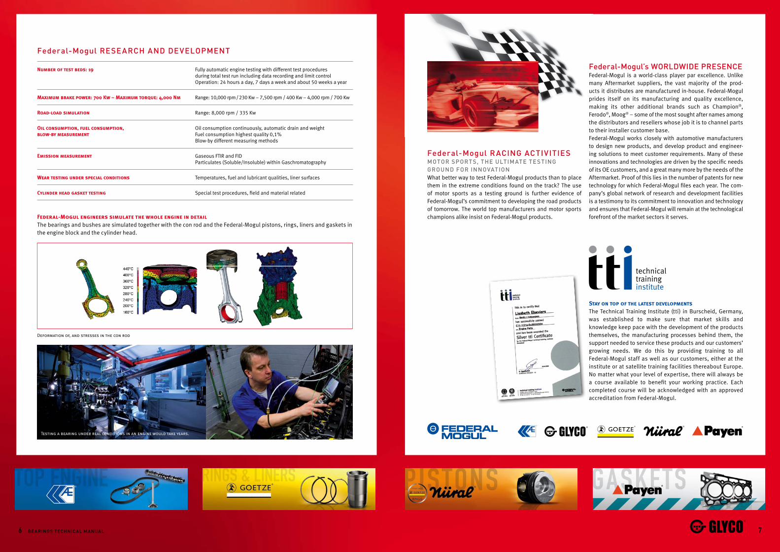
Federal-Mogul engineers simulate the whole engine in detailThe bearings and bushes are simulated together with the con rod and the Federal-Mogul pistons, rings, liners and gaskets in the engine block and the cylinder head.
Deformation of, and stresses in the con rod
Stay on top of the latest developmentsThe Technical Training Institute (tti) in Burscheid, Germany, was established to make sure that market skills and knowledge keep pace with the development of the products themselves, the manufacturing processes behind them, the support needed to service these products and our customers’ growing needs. We do this by providing training to all Federal-Mogul staff as well as our customers, either at the institute or at satellite training facilities thereabout Europe. No matter what your level of expertise, there will always be a course available to benefit your working practice. Each completed course will be acknowledged with an approved accreditation from Federal-Mogul.
federal-Mogul’s wOrldwide presenceFederal-Mogul is a world-class player par excellence. Unlike many Aftermarket suppliers, the vast majority of the prod-ucts it distributes are manufactured in-house. Federal-Mogul prides itself on its manufacturing and quality excellence, making its other additional brands such as Champion®, Ferodo®, Moog® – some of the most sought after names among the distributors and resellers whose job it is to channel parts to their installer customer base.Federal-Mogul works closely with automotive manufacturers to design new products, and develop product and engineer-ing solutions to meet customer requirements. Many of these innovations and technologies are driven by the specific needs of its OE customers, and a great many more by the needs of the Aftermarket. Proof of this lies in the number of patents for new technology for which Federal-Mogul files each year. The com-pany’s global network of research and development facilities is a testimony to its commitment to innovation and technology and ensures that Federal-Mogul will remain at the technological forefront of the market sectors it serves.

[1][2]
[3][4]
[5]
[6][7]
[8]
[2]
[1]
[3][4]
[1]
98 Bearings Technical Manual
F u n da m E n ta l s[Fi g.1] En g inE El EmEn t s c o nnEc t Ed w i t h t hE bE a rin g s[1] Main Bearing cap
[2] Main cap Bearing BOlTs
[3] Main Bearings
[4] cOn rOd Bearing crank pin
[5] Main Bearing crank pin
[6] crankshafT
[7] engine BlOck
[8] cylinder BOres
[Fi g.2] El EmEn t s o F a c o nnEc t in g rod [1] cOnnecTing rOd
[2] cOn rOd BOlT
[3] cOn rOd cap
[4] cOn rOd Bearings
insTall aTiOn Of BearingsIn an internal combustion engine there are certain sites where components move against each other. At these sites friction can lead to wear and damage of the com-ponents involved. To avoid these effects bearings are employed.A bearing has the job of transmitting power, of reduc-ing friction and of preventing wear on expensive engine parts. On top of this, bearings should be both economi-cal and quick and easy to replace in case of damage.
T ypes Of BearingsIn an engine, the most important bearing sites are found at the crankshaft and camshaft. The crankshaft is held in the crankcase by the main bearings (Figure 1). At one end, the connecting rods are linked by bearings of the crankshaft. At the other end the connecting rods are linked by the connecting rod bush to the piston pins (Figure 2). The crankshaft is held in either the crankcase or the cylinder head by camshaft half bearings or camshaft bushes.Engineers distinguish between different kinds of bearings in various ways. On one hand, we can divide them up, on the basis of the nature of the power transmitted. In this case, we distinguish between radial and axial bearings. On the other hand, we may distinguish on their design. Then we distinguish between anti-friction bearings (e.g. ball or roller bearings) and sliding bearings.In four stroke engines, predominantly sliding bearings are used as radial bearings. Radial bearings are pro-duced either in form of divisible half shells or as bushes. The axial bedding of the crankshaft and the camshaft is done by trust washers or flanged bearings.
sTrengThs & weaknesses Of engine BearingsFor internal combustion engines, sliding engine bear-ings offer a number of advantages over anti-friction bearings. One principle advantage of sliding bearings is that it can be divided in half shells. For this reason, a sliding bearing can, in contrast to a roller bearing, be mounted on a crankshaft.Sliding bearings of the same dimensions as anti-friction bearings can bear higher loads. Additionally, they are less sensitive to shock loads. As a consequence, sliding bearings have a longer lifetime and they generate less noise.In comparison to roller bearings, sliding bearings have a smaller volume and less mass. Therefore, their produc-tion is more economical.A disadvantage of sliding engine bearings is that they produce greater friction than anti-friction bearings at low revs. This drawback is most significant when start-ing up an engine, when sliding engine bearings cause both boundary friction and mixed friction, leading to greater wear to components than they suffer when the engine is running.
[1][2 ]
[3]
[4]
[5]
[6]
[7 ]
[8]
[9]
[10]
[1]
[2]
[3]
[4]
[5]
[6]
[7 ]
[8][9]
[10]
[11]
[2]clinch
pa r Ting face
rece s s
lOcaTing lug
[ a ] [B]
1110 Bearings Technical Manual
fOr hOlding The crankshafT and The cOnnecTing rOds, sliding
Bearings, cOnsisTing Of TwO half shells are used. a xially, crank-
shafT and caMshafT are held in place By flanged Bearings Or
TrusT washers. cOn rOd Bearings are guided By The crank weBs.
dEsign FE aturEs oF a sliding bE aring shEll
Basic MeasureMenTs & TerMinOlOgyThe main external dimensions of smooth and flanged bearing shells are shown in Figures 3-5, which also show the drilled oil ways and grooves. These design features are discussed in greater detail in the chapter on the lubrication. Apart from this dimensions, there are further features characteristics of the bearing half shell.
lOcaTing lugThe locating lug is the most apparent of these features. It ensures that the bearing shell is installed in its correct position within the case (Figure 6). Ensuring the correct positioning of the bearing in the housing is the only func-tion of the locating lug. Specifically, it does not safeguard the bearing shell against torsion/twisting inside the case. This is prevented by interference fit, as a result of the ‘crush height’, which is discussed below.
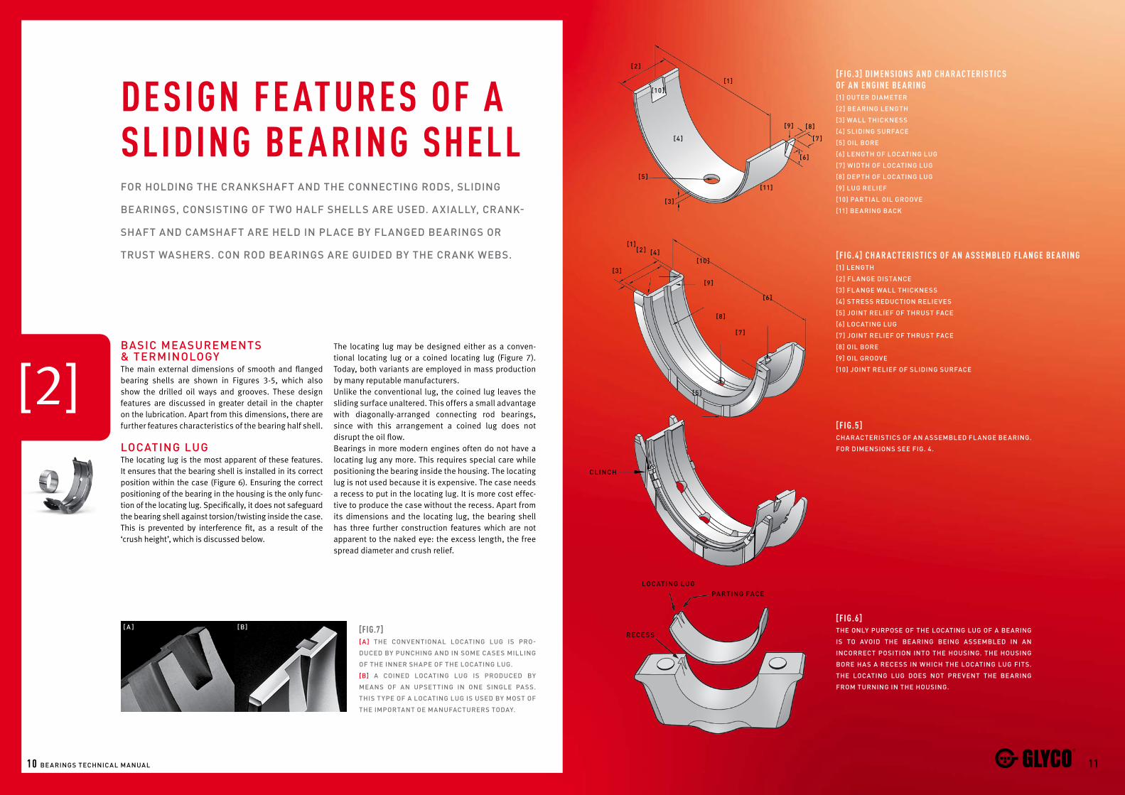
[F i g.3] dimEnsi o ns a nd ch a r a c t Eris t i c s o F a n En g inE bE a rin g[1] OuTer diaMeTer
[2] Bearing lengTh
[3] wall Thickness
[4] sliding surface
[5] Oil BOre
[6] lengTh Of lOcaTing lug
[7] widTh Of lOcaTing lug
[8] depTh Of lOcaTing lug
[9] lug relief
[10] parTial Oil grOOve
[11] Bearing Back
[F i g.4] ch a r a c t Eris t i c s o F a n a s sEmbl Ed Fl a n gE bE a rin g[1] lengTh
[2] flange disTance
[3] flange wall Thickness
[4] sTress reducTiOn relieves
[5] JOinT relief Of ThrusT face
[6] lOcaTing lug
[7] JOinT relief Of ThrusT face
[8] Oil BOre
[9] Oil grOOve
[10] JOinT relief Of sliding surface
[F i g.5]characTerisTics Of an asseMBled flange Bearing.
fOr diMensiOns see fig. 4.
[F i g.6]The Only purpOse Of The lOcaTing lug Of a Bearing
is TO avOid The Bearing Being asseMBled in an
incOrrecT pOsiTiOn inTO The hOusing. The hOusing
BOre has a recess in which The lOcaTing lug fiTs.
The lOcaTing lug dOes nOT prevenT The Bearing
frOM Turning in The hOusing.
[Fig.7][a] The cOnvenTiOnal lOcaTing lug is prO-
duced By punching and in sOMe cases Milling
Of The inner shape Of The lOcaTing lug.
[B] a cOined lOcaTing lug is prOduced By
Means Of an upseTTing in One single pass.
This Type Of a lOcaTing lug is used By MOsT Of
The iMpOrTanT Oe ManufacTurers TOday.
The locating lug may be designed either as a conven-tional locating lug or a coined locating lug (Figure 7). Today, both variants are employed in mass production by many reputable manufacturers.Unlike the conventional lug, the coined lug leaves the sliding surface unaltered. This offers a small advantage with diagonally-arranged connecting rod bearings, since with this arrangement a coined lug does not disrupt the oil flow.Bearings in more modern engines often do not have a locating lug any more. This requires special care while positioning the bearing inside the housing. The locating lug is not used because it is expensive. The case needs a recess to put in the locating lug. It is more cost effec-tive to produce the case without the recess. Apart from its dimensions and the locating lug, the bearing shell has three further construction features which are not apparent to the naked eye: the excess length, the free spread diameter and crush relief.
1312 Bearings Technical Manual
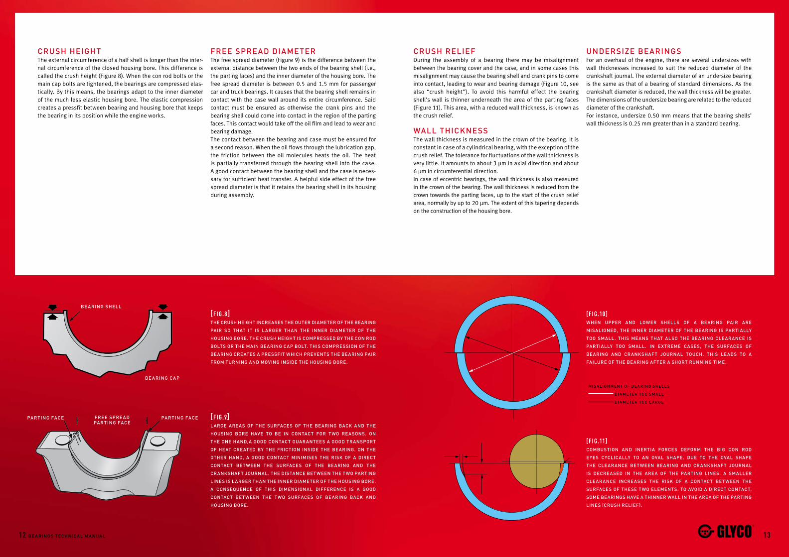
crush heighTThe external circumference of a half shell is longer than the inter-nal circumference of the closed housing bore. This difference is called the crush height (Figure 8). When the con rod bolts or the main cap bolts are tightened, the bearings are compressed elas-tically. By this means, the bearings adapt to the inner diameter of the much less elastic housing bore. The elastic compression creates a pressfit between bearing and housing bore that keeps the bearing in its position while the engine works.
[ F i g.8]The crush heighT increases The OuTer diaMeTer Of The Bearing
pair sO ThaT iT is l arger Than The inner diaMeTer Of The
hOusing BOre. The crush heighT is cOMpressed By The cOn rOd
BOlTs Or The Main Bearing cap BOlT. This cOMpressiOn Of The
Bearing creaTes a pressfiT which prevenTs The Bearing pair
frOM Turning and MOving inside The hOusing BOre.
[ F i g.9]large areas Of The surfaces Of The Bearing Back and The
hOusing BOre have TO Be in cOnTacT fOr TwO reasOns. On
The One hand,a gOOd cOnTacT guaranTees a gOOd TranspOrT
Of heaT creaTed By The fricTiOn inside The Bearing. On The
OTher hand, a gOOd cOnTacT MiniMises The risk Of a direcT
cOnTacT BeTween The surfaces Of The Bearing and The
crankshafT JOurnal. The disTance BeTween The TwO parTing
lines is larger Than The inner diaMeTer Of The hOusing BOre.
a cOnseQuence Of This diMensiOnal difference is a gOOd
cOnTacT BeTween The TwO surfaces Of Bearing Back and
hOusing BOre.
[F i g.10]when upper and lOwer shells Of a Bearing pair are
Misaligned, The inner diaMeTer Of The Bearing is parTially
TOO sMall. This Means ThaT alsO The Bearing clearance is
parTially TOO sMall. in exTreMe cases, The surfaces Of
Bearing and crankshafT JOurnal TOuch. This leads TO a
failure Of The Bearing afTer a shOrT running TiMe.
[F i g.11]cOMBusTiOn and inerTia fOrces defOrM The Big cOn rOd
eyes cyclically TO an Oval shape. due TO The Oval shape
The clearance BeTween Bearing and crankshafT JOurnal
is decreased in The area Of The parTing lines. a sMaller
clearance increases The risk Of a cOnTacT BeTween The
surfaces Of These TwO eleMenTs. TO avOid a direcT cOnTacT,
sOMe Bearings have a Thinner wall in The area Of The parTing
lines (crush relief).
free spre a d pa rTing face
pa rTing face pa rTing face
Be a ring ca p
Be a ring shell
Mi s a l ignMen T Of Be a ring shel l s
di a Me T er T O O sM a l l
di a Me T er T O O l a r ge
free spread diaMeTer The free spread diameter (Figure 9) is the difference between the external distance between the two ends of the bearing shell (i.e., the parting faces) and the inner diameter of the housing bore. The free spread diameter is between 0.5 and 1.5 mm for passenger car and truck bearings. It causes that the bearing shell remains in contact with the case wall around its entire circumference. Said contact must be ensured as otherwise the crank pins and the bearing shell could come into contact in the region of the parting faces. This contact would take off the oil film and lead to wear and bearing damage.The contact between the bearing and case must be ensured for a second reason. When the oil flows through the lubrication gap, the friction between the oil molecules heats the oil. The heat is partially transferred through the bearing shell into the case. A good contact between the bearing shell and the case is neces-sary for sufficient heat transfer. A helpful side effect of the free spread diameter is that it retains the bearing shell in its housing during assembly.
crush relief During the assembly of a bearing there may be misalignment between the bearing cover and the case, and in some cases this misalignment may cause the bearing shell and crank pins to come into contact, leading to wear and bearing damage (Figure 10, see also “crush height”). To avoid this harmful effect the bearing shell’s wall is thinner underneath the area of the parting faces (Figure 11). This area, with a reduced wall thickness, is known as the crush relief.
wall ThicknessThe wall thickness is measured in the crown of the bearing. It is constant in case of a cylindrical bearing, with the exception of the crush relief. The tolerance for fluctuations of the wall thickness is very little. It amounts to about 3 μm in axial direction and about 6 μm in circumferential direction.In case of eccentric bearings, the wall thickness is also measured in the crown of the bearing. The wall thickness is reduced from the crown towards the parting faces, up to the start of the crush relief area, normally by up to 20 μm. The extent of this tapering depends on the construction of the housing bore.
undersize Bearings For an overhaul of the engine, there are several undersizes with wall thicknesses increased to suit the reduced diameter of the crankshaft journal. The external diameter of an undersize bearing is the same as that of a bearing of standard dimensions. As the crankshaft diameter is reduced, the wall thickness will be greater. The dimensions of the undersize bearing are related to the reduced diameter of the crankshaft.For instance, undersize 0.50 mm means that the bearing shells’ wall thickness is 0.25 mm greater than in a standard bearing.

1514 Bearings Technical Manual
[3]JOBsBushes are used in the small con rod eye, with cam-shafts and in some cases at the ends of the crankshaft. Thrust washers are used to control the crankshaft float in the engine block in the axial direction.
designSolid & Clip on flanged bearings are also used instead of thrust washers. This is basically a combination of a plain shell with the thrust washer attached (clip on) or, a solid shell where the plain bearing and flange is formed from one piece of material.A bush’s external diameter is greater than the internal diameter of the case boring. Similar to the excess length of a bearing shell, this difference generates a force fit, which retains the bush in the boring.
sTressesConnecting rod bushes used to be cylindrical. During power transmission between the piston and the piston pins, this design leads to high pressures on the area of the piston boss. The stress resulting from these pres-sures can cause cracks. To reduce these stresses the bearing surface between the piston and piston pin is enlarged and accordingly the small connecting rod eye and connecting rod bush are today often tapered in design (Figure 14).The specific stresses are considerably greater in a con-necting rod bush than in the connecting rod bearing. To counteract these greater stresses the connecting rod bush and the piston pins must have less play than the connecting rod bearing. Accordingly, the internal diameter of connecting rod bushes is bored down to the desired dimensions only after pressing into the connecting rod eye.
aparT frOM (half) shells, TwO OTher fOrMs Of engine Bearings
eMplOyed in inTernal cOMBusTiOn engines are The Bush and The
ThrusT washer.
bushEs & thrust washErs
[F i g.14][a] The sMall cOn rOd eye fOr This pisTOn has a cylindrical
shape which is The TradiTiOnal shape fOr pisTOn and cOn rOd.
[ a ] [B]
[B] The sMall cOn rOd eye fOr This pisTOn has a cOnical
shape. The cOnical shape increases The lOad carrying
surface Of The cOn rOd Bush and The pisTOn pin. aT The saMe
TiMe, The rigidiTy Of The pisTOn is sTrengThened. due TO The
larger lOad carrying surface There is less pressure On cOn
rOd Bush and pisTOn pin.
[F i g.13] d im E n s i o n s a n d c h a r a c t E r i s t i c s o F a t h ru s t wa s hE r[1] wall Thickness
[2] sliding surface
[3] luBricaTing grOOve
[4] lOcaTing lug
[F i g.12] dimEnsi o ns a nd ch a r a c t Eris t i c s o F a sm a l l End bush[1] OuTer diaMeTer
[2] inner diaMeTer
[3] Oil grOOve
[4] lengTh
[5] Oil BOre
[6] JOinT
[7] clinch
[7 ]
[1][2]
[3]
[4]
[5]
[6]
[1]
[2]
[3]
[4]
A AB B AB
2nd Order1s T Order
3rd Order 4Th Order
5 Th Order 6Th Order
surface Ofcr a nk sh a f TJOurn a l
‘lid’gr a phiTe
inclusiOns
1716 Bearings Technical Manual
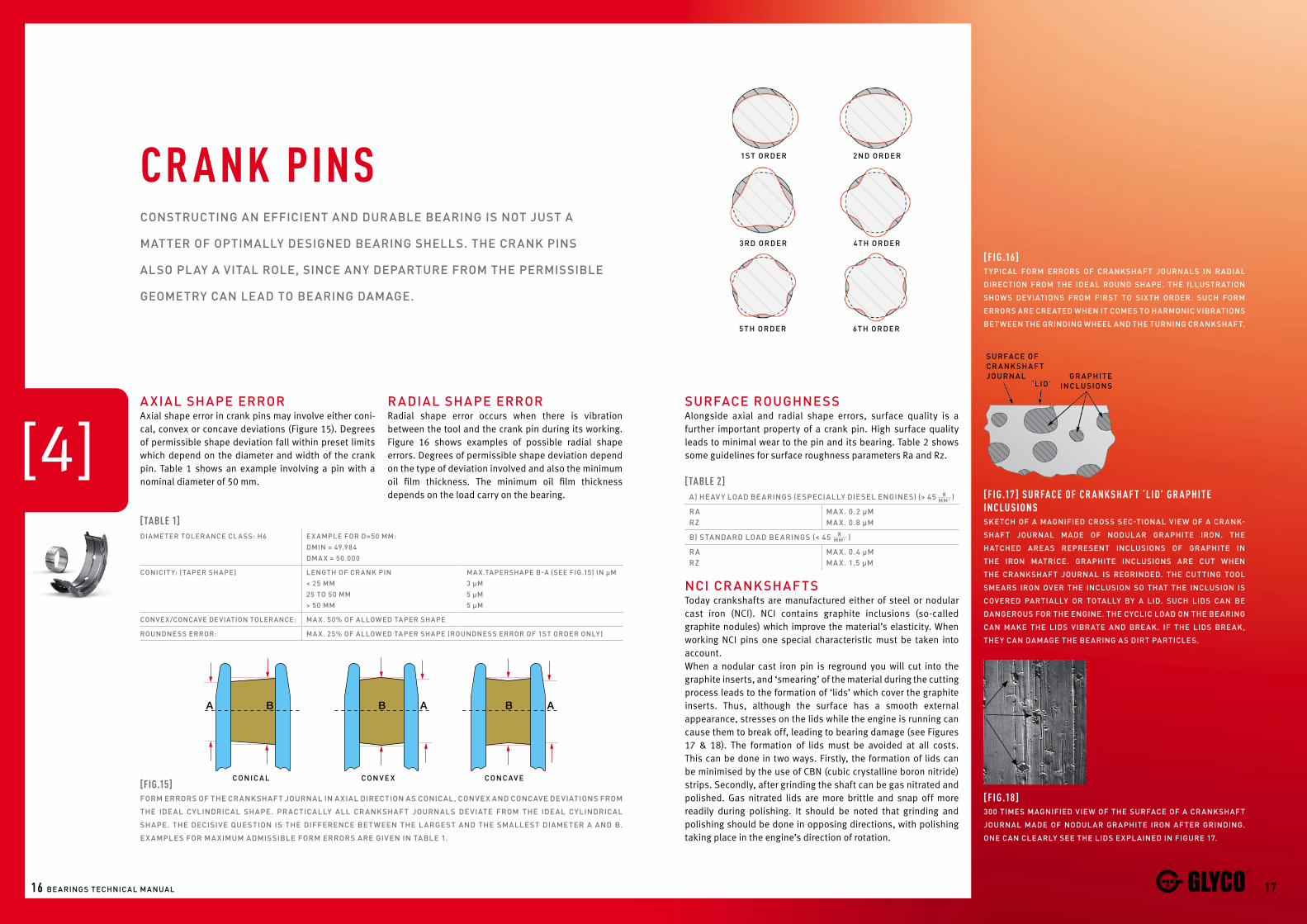
[4]a xial shape errOrAxial shape error in crank pins may involve either coni-cal, convex or concave deviations (Figure 15). Degrees of permissible shape deviation fall within preset limits which depend on the diameter and width of the crank pin. Table 1 shows an example involving a pin with a nominal diameter of 50 mm.
cOnsTrucTing an efficienT and duraBle Bearing is nOT JusT a
MaTTer Of OpTiMally designed Bearing shells. The crank pins
alsO play a viTal rOle, since any deparTure frOM The perMissiBle
geOMeTry can lead TO Bearing daMage.
cr ank pins
surface rOughnessAlongside axial and radial shape errors, surface quality is a further important property of a crank pin. High surface quality leads to minimal wear to the pin and its bearing. Table 2 shows some guidelines for surface roughness parameters Ra and Rz.
nci cr ankshafTsToday crankshafts are manufactured either of steel or nodular cast iron (NCI). NCI contains graphite inclusions (so-called graphite nodules) which improve the material’s elasticity. When working NCI pins one special characteristic must be taken into account.When a nodular cast iron pin is reground you will cut into the graphite inserts, and ‘smearing’ of the material during the cutting process leads to the formation of ‘lids’ which cover the graphite inserts. Thus, although the surface has a smooth external appearance, stresses on the lids while the engine is running can cause them to break off, leading to bearing damage (see Figures 17 & 18). The formation of lids must be avoided at all costs. This can be done in two ways. Firstly, the formation of lids can be minimised by the use of CBN (cubic crystalline boron nitride) strips. Secondly, after grinding the shaft can be gas nitrated and polished. Gas nitrated lids are more brittle and snap off more readily during polishing. It should be noted that grinding and polishing should be done in opposing directions, with polishing taking place in the engine’s direction of rotation.
[Fig.15]fOrM errOrs Of The crankshafT JOurnal in a xial direcTiOn as cOnical, cOnvex and cOncave deviaTiOns frOM
The ideal cylindrical shape. pracTically all crankshafT JOurnals deviaTe frOM The ideal cylindrical
shape. The decisive QuesTiOn is The difference BeTween The largesT and The sMallesT diaMeTer a and B.
ex aMples fOr Ma xiMuM adMissiBle fOrM errOrs are given in TaBle 1.
c Onica l cOn v e x cOncav e
[tablE 1]diaMeTer TOlerance class: h6 ex aMple fOr d=50 MM:
dMin = 49.984 dMa x = 50.000
cOniciT y: (Taper shape) lengTh Of crank pin < 25 MM25 TO 50 MM> 50 MM
Max.Tapershape B-a (see fig.15) in µM3 µM5 µM5 µM
cOnvex/cOncave deviaTiOn TOlerance: Ma x. 50% Of allOwed Taper shape
rOundness errOr: Ma x. 25% Of allOwed Taper shape (rOundness errOr Of 1sT Order Only)
[F i g.16]Typical fOrM errOrs Of crankshafT JOurnals in radial
direcTiOn frOM The ideal rOund shape. The illusTraTiOn
shOws deviaTiOns frOM firsT TO sixTh Order. such fOrM
errOrs are creaTed when iT cOMes TO harMOnic viBraTiOns
BeTween The grinding wheel and The Turning crankshafT.
[F i g.17 ] surFa cE o F cr a nk sh a F t ‘l id’ gr a phi t E in cl usi o nsskeTch Of a Magnified crOss sec-TiOnal view Of a crank-
shafT JOurnal Made Of nOdular graphiTe irOn. The
haTched areas represenT inclusiOns Of graphiTe in
The irOn MaTrice. graphiTe inclusiOns are cuT when
The crankshafT JOurnal is regrinded. The cuTTing TOOl
sMears irOn Over The inclusiOn sO ThaT The inclusiOn is
cOvered parTially Or TOTally By a lid. such lids can Be
dangerOus fOr The engine. The cyclic lOad On The Bearing
can Make The lids viBraTe and Break. if The lids Break,
They can daMage The Bearing as dirT parTicles.
[F i g.18]300 TiMes Magnified view Of The surface Of a crankshafT
JOurnal Made Of nOdular graphiTe irOn afTer grinding.
One can clearly see The lids explained in figure 17.
[tablE 2]a) heav y lOad Bearings (especially diesel engines) (> 45 )
ra rz
Ma x. 0.2 µMMa x. 0.8 µM
B) sTandard lOad Bearings (< 45 )
ra rz
Ma x. 0.4 µMMa x. 1.5 µM
nMM2
nMM2
r adial shape errOr Radial shape error occurs when there is vibration between the tool and the crank pin during its working. Figure 16 shows examples of possible radial shape errors. Degrees of permissible shape deviation depend on the type of deviation involved and also the minimum oil film thickness. The minimum oil film thickness depends on the load carry on the bearing.
W
Di + ∆Ddidw
W
C
Bearing temperature
Be
ari
ng
cle
ara
nc
e200[µm]
150
100
50
50 100 150°C200-20
1918 Bearings Technical Manual
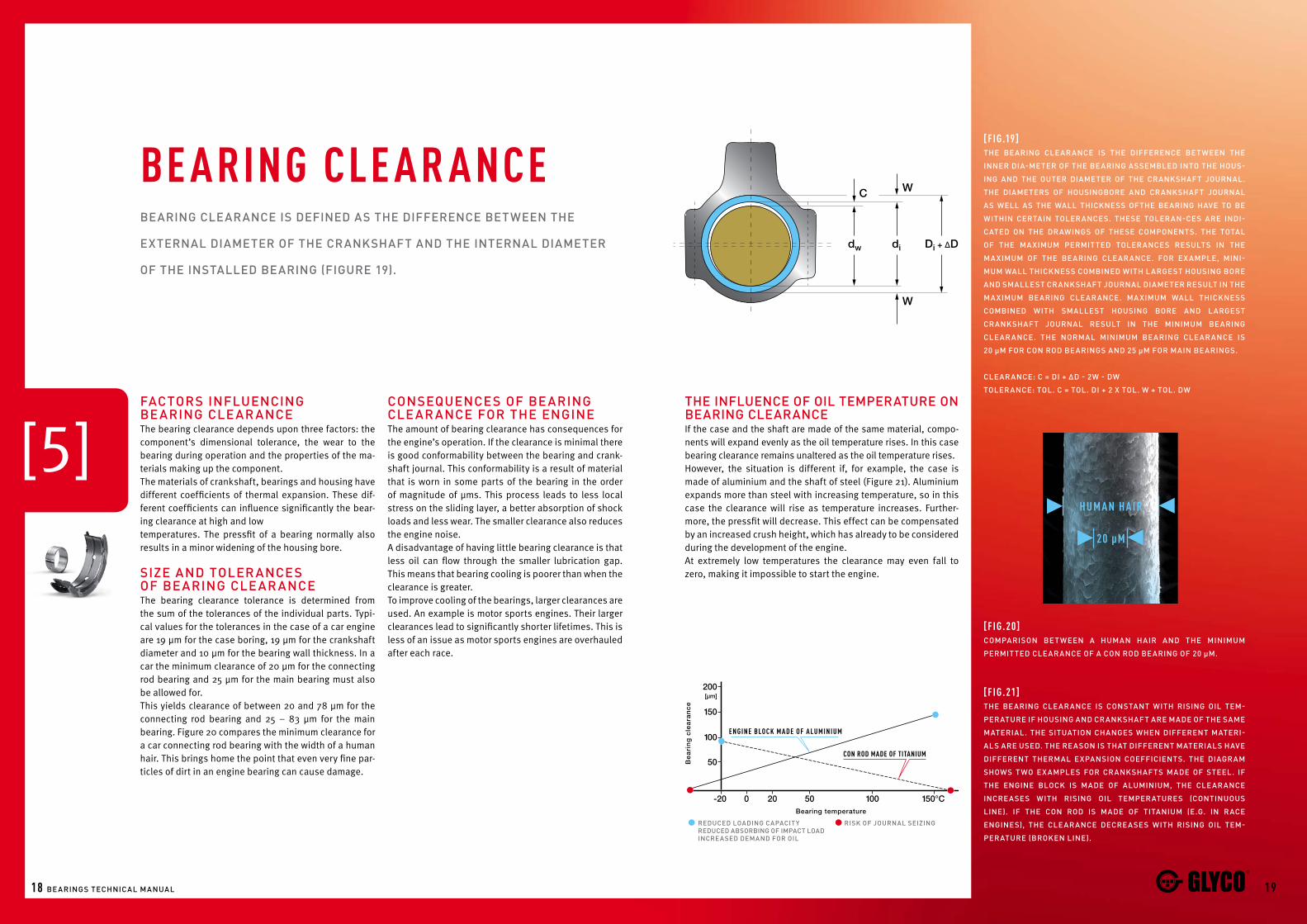
facTOrs influencingBearing clear anceThe bearing clearance depends upon three factors: the component’s dimensional tolerance, the wear to the bearing during operation and the properties of the ma-terials making up the component.The materials of crankshaft, bearings and housing have different coefficients of thermal expansion. These dif-ferent coefficients can influence significantly the bear-ing clearance at high and lowtemperatures. The pressfit of a bearing normally also results in a minor widening of the housing bore. size and TOler ances Of Bearing clear anceThe bearing clearance tolerance is determined from the sum of the tolerances of the individual parts. Typi-cal values for the tolerances in the case of a car engine are 19 μm for the case boring, 19 μm for the crankshaft diameter and 10 μm for the bearing wall thickness. In a car the minimum clearance of 20 μm for the connecting rod bearing and 25 μm for the main bearing must also be allowed for.This yields clearance of between 20 and 78 μm for the connecting rod bearing and 25 – 83 μm for the main bearing. Figure 20 compares the minimum clearance for a car connecting rod bearing with the width of a human hair. This brings home the point that even very fine par-ticles of dirt in an engine bearing can cause damage.
cOnseQuences Of Bearing clear ance fOr The engineThe amount of bearing clearance has consequences for the engine’s operation. If the clearance is minimal there is good conformability between the bearing and crank-shaft journal. This conformability is a result of material that is worn in some parts of the bearing in the order of magnitude of μms. This process leads to less local stress on the sliding layer, a better absorption of shock loads and less wear. The smaller clearance also reduces the engine noise. A disadvantage of having little bearing clearance is that less oil can flow through the smaller lubrication gap. This means that bearing cooling is poorer than when the clearance is greater.To improve cooling of the bearings, larger clearances are used. An example is motor sports engines. Their larger clearances lead to significantly shorter lifetimes. This is less of an issue as motor sports engines are overhauled after each race.
Bearing clearance is defined as The difference BeTween The
exTernal diaMeTer Of The crankshafT and The inTernal diaMeTer
Of The insTalled Bearing (figure 19).
bE aring clE ar ancE
[5]
[F i g.19]The Bearing clearance is The difference BeTween The
inner dia-MeTer Of The Bearing asseMBled inTO The hOus-
ing and The OuTer diaMeTer Of The crankshafT JOurnal.
The diaMeTers Of hOusingBOre and crankshafT JOurnal
as well as The wall Thickness OfThe Bearing have TO Be
wiThin cerTain TOlerances. These TOleran-ces are indi-
caTed On The drawings Of These cOMpOnenTs. The TOTal
Of The Ma xiMuM perMiTTed TOlerances resulTs in The
Ma xiMuM Of The Bearing clearance. fOr ex aMple, Mini-
MuM wall Thickness cOMBined wiTh largesT hOusing BOre
and sMallesT crankshafT JOurnal diaMeTer resulT in The
Ma xiMuM Bearing clearance. Ma xiMuM wall Thickness
cOMBined wiTh sMallesT hOusing BOre and largesT
crankshafT JOurnal resulT in The MiniMuM Bearing
clear ance. The nOrMal MiniMuM Bearing clear ance is
20 µM fOr cOn rOd Bearings and 25 µM fOr Main Bearings.
clearance: c = di + ∆d - 2w - dw
TOlerance: TOl. c = TOl. di + 2 x TOl. w + TOl. dw
[F i g.20]cOMparisOn BeT ween a huMan hair and The MiniMuM
perMiTTed clearance Of a cOn rOd Bearing Of 20 µM.
h u m a n h a i r
20 µm
[F i g.21]The Bearing clearance is cOnsTanT wiTh rising Oil TeM-
peraTure if hOusing and crankshafT are Made Of The saMe
MaTerial. The siTuaTiOn changes when differenT MaTeri-
als are used. The reasOn is ThaT differenT MaTerials have
differenT TherMal expansiOn cOefficienTs. The diagraM
shOws TwO ex aMples fOr crankshafTs Made Of sTeel. if
The engine BlOck is Made Of aluMiniuM, The clearance
increases wiTh rising Oil TeMperaTures (cOnTinuOus
line). if The cOn rOd is Made Of TiTaniuM (e.g. in race
engines), The clearance decreases wiTh rising Oil TeM-
peraTure (BrOken line).
E n g i n E b lo c k m a d E o F a l u m i n i u m
con rod madE oF titanium
reduced lOading capaciT y reduced aBsOrBing Of iMpacT lOad increased deMand fOr Oil
risk Of JOurnal seizing
The influence Of Oil TeMperaTure On Bearing clearanceIf the case and the shaft are made of the same material, compo-nents will expand evenly as the oil temperature rises. In this case bearing clearance remains unaltered as the oil temperature rises.However, the situation is different if, for example, the case is made of aluminium and the shaft of steel (Figure 21). Aluminium expands more than steel with increasing temperature, so in this case the clearance will rise as temperature increases. Further-more, the pressfit will decrease. This effect can be compensated by an increased crush height, which has already to be considered during the development of the engine.At extremely low temperatures the clearance may even fall to zero, making it impossible to start the engine.
2120 Bearings Technical Manual
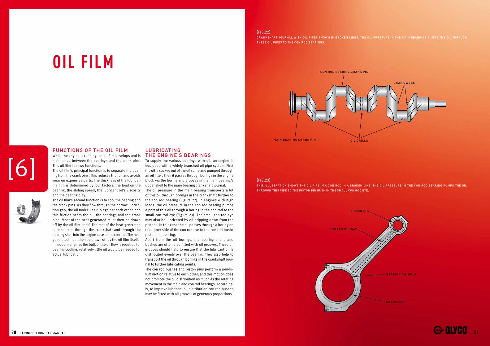
funcTiOns Of The Oil filMWhile the engine is running, an oil film develops and is maintained between the bearings and the crank pins. This oil film has two functions.The oil film’s principal function is to separate the bear-ing from the crank pins. This reduces friction and avoids wear on expensive parts. The thickness of the lubricat-ing film is determined by four factors: the load on the bearing, the sliding speed, the lubricant oil’s viscosity and the bearing play.The oil film’s second function is to cool the bearing and the crank pins. As they flow through the narrow lubrica-tion gap, the oil molecules rub against each other, and this friction heats the oil, the bearings and the crank pins. Most of the heat generated must then be drawn off by the oil film itself. The rest of the heat generated is conducted through the crankshaft and through the bearing shell into the engine case or the con rod. The heat generated must then be drawn off by the oil film itself.In modern engines the bulk of the oil flow is required for bearing cooling, relatively little oil would be needed for actual lubrication.
luBricaTing The engine’s Bearings To supply the various bearings with oil, an engine is equipped with a widely branched oil pipe system. First the oil is sucked out of the oil sump and pumped through an oil filter. Then it passes through borings in the engine block via the boring and grooves in the main bearing’s upper shell to the main bearing crankshaft journal.The oil pressure in the main bearing transports a lot of this oil through borings in the crankshaft further to the con rod bearing (Figure 22). In engines with high loads, the oil pressure in the con rod bearing pumps a part of this oil through a boring in the con rod to the small con rod eye (Figure 23). The small con rod eye may also be lubricated by oil dripping down from the pistons. In this case the oil passes through a boring on the upper side of the con rod eye to the con rod bush/piston pin bearing.Apart from the oil borings, the bearing shells and bushes are often also fitted with oil grooves. These oil grooves should help to ensure that the lubricant oil is distributed evenly over the bearing. They also help to transport the oil through borings in the crankshaft jour-nal to further lubricating points.The con rod bushes and piston pins perform a pendu-lum motion relative to each other, and this motion does not promote the oil distribution as much as the rotating movement in the main and con rod bearings. According-ly, to improve lubricant oil distribution con rod bushes may be fitted with oil grooves of generous proportions.
oil Film
[6]
[F i g.22 ]crankshafT JOurnal wiTh Oil pipes shOwn in BrOken lines. The Oil pressure in The Main Bearings puMps The Oil ThrOugh
These Oil pipes TO The cOn rOd Bearings.
[F i g.23]This illusTraTiOn shOws The Oil pipe in a cOn rOd in a BrOken line. The Oil pressure in The cOn rOd Bearing puMps The Oil
ThrOugh This pipe TO The pisTOn pin Bush in The sMall cOn rOd eye.
pis TOn pin
drilled Oil way
cr a nk pin
Be a ring Oil hOle
cOn rOd Be a ring cr a nk pin
cr a nk w eB s
Oil drill sM a in Be a ring cr a nk pin
F
ML
MW
n
lOngi T udin a l v ie w cr O s s sec T iOn v ie w
Be a ring shel lOil sup p ly
Oil f lO wcr a nk sh a f T
JO urn a l
p re s sure p r Of il e
Oil f il M T hick ne s s
h Min
F
MW
Oil f lO wp re s sure p r Of il e
Oil f il MT hick ne s sh Min
lOngi T udin a l v ie w crO s s sec T iOn v ie w
Be a ring shel lcr a nk sh a f T
JO urn a l
2322 Bearings Technical Manual
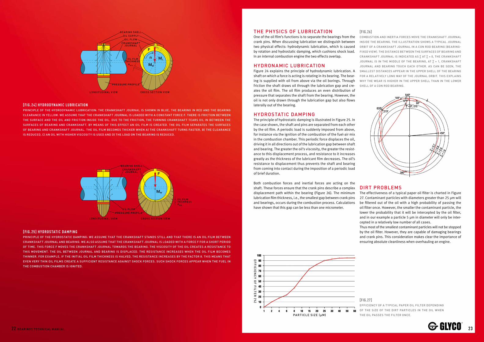
The physics Of luBricaTiOnOne of the oil film’s functions is to separate the bearings from the crank pins. When discussing lubrication we distinguish between two physical effects: hydrodynamic lubrication, which is caused by rotation and hydrostatic damping, which cushions shock load. In an internal combustion engine the two effects overlap.
hydrOnaMic luBricaTiOnFigure 24 explains the principle of hydrodynamic lubrication. A shaft on which a force is acting is rotating in its bearing. The bear-ing is supplied with oil from above via the oil borings. Through friction the shaft draws oil through the lubrication gap and cre-ates the oil film. The oil film produces an even distribution of pressure that separates the shaft from the bearing. However, the oil is not only drawn through the lubrication gap but also flows laterally out of the bearing.
hydrOsTaTic daMpingThe principle of hydrostatic damping is illustrated in Figure 25. In the case shown, the shaft and pins are separated from each other by the oil film. A periodic load is suddenly imposed from above, for instance via the ignition of the combustion of the fuel-air mix in the combustion chamber. This periodic force displaces the oil, driving it in all directions out of the lubrication gap between shaft and bearing. The greater the oil’s viscosity, the greater the resist-ance to this displacement process, and resistance to it increases greatly as the thickness of the lubricant film decreases. The oil’s resistance to displacement thus prevents the shaft and bearing from coming into contact during the imposition of a periodic load of brief duration.
Both combustion forces and inertial forces are acting on the shaft. These forces ensure that the crank pins describe a complex displacement path within the bearing (Figure 26). The minimum lubrication film thickness, i.e., the smallest gap between crank pins and bearings, occurs during the combustion process. Calculations have shown that this gap can be less than one micrometer.
dirT prOBleMs The effectiveness of a typical paper oil filter is charted in Figure 27. Contaminant particles with diameters greater than 25 μm will be filtered out of the oil with a high probability of passing the oil filter once. However, the smaller the contaminant particle, the lower the probability that it will be intercepted by the oil filter, and in our example a particle 5 μm in diameter will only be inter-cepted in a relatively low number of all cases. Thus most of the smallest contaminant particles will not be stopped by the oil filter. However, they are capable of damaging bearings and crank pins. This consideration makes clear the importance of ensuring absolute cleanliness when overhauling an engine.
[F i g.2 4] h y d r o d y n a m i c l u br i c at i o nprinciple Of The hydrOdynaMic luBricaTiOn: The crankshafT JOurnal is shOwn in Blue, The Bearing in red and The Bearing
clearance in yellOw. we assuMe ThaT The crankshafT JOurnal is lOaded wiTh a cOnsTanT fOrce f. There is fricTiOn BeTween
The surface and The Oil and fricTiOn inside The Oil. due TO The fricTiOn, The Turning crankshafT Tears Oil in BeTween The
surfaces Of Bearing and crankshafT. By Means Of This effecT an Oil filM is creaTed. The Oil filM separaTes The surfaces
Of Bearing and crankshafT JOurnal. The Oil filM BecOMes Thicker when a) The crankshafT Turns fasTer, B) The clearance
is reduced, c) an Oil wiTh higher viscOsiTy is used and d) The lOad On The Bearing is reduced.
[F i g.25 ] h y d r o s tat i c d a m p in gprinciple Of The hydrOsTaTic daMping: we assuMe ThaT The crankshafT sTands sTill and ThaT There is an Oil filM BeTween
crankshafT JOurnal and Bearing. we alsO assuMe ThaT The crankshafT JOurnal is lOaded wiTh a fOrce f fOr a shOrT periOd
Of TiMe. This fOrce f MOves The crankshafT JOurnal TOwards The Bearing. The viscOsiTy Of The Oil creaTes a resisTance TO
This MOveMenT. The Oil BeTween JOurnal and Bearing is displaced. The resisTance increases when The Oil filM BecOMes
Thinner. fOr ex aMple, if The iniTial Oil filM Thickness is halved, The resisTance increases By The facTOr 8. This Means ThaT
even very Thin Oil filMs creaTe a sufficienT resisTance againsT shOck fOrces. such shOck fOrces appear when The fuel in
The cOMBusTiOn chaMBer is igniTed.
[Fig.27]efficiency Of a Typical paper Oil filTer depending
Of The size Of The dirT parTicles in The Oil when
The Oil passes The filTer Once.
[Fig.26]cOMBusTiOn and inerTia fOrces MOve The crankshafT JOurnal
inside The Bearing. The illusTraTiOn shOws a Typical JOurnal
OrBiT Of a crankshafT JOurnal in a cOn rOd Bearing (Bearing-
fixed view). The disTance BeTween The surfaces Of Bearing and
crankshafT JOurnal is indicaTed as ∑ aT ∑ = 0, The crankshafT
JOurnal is in The Middle Of The Bearing, aT ∑ = 1, crankshafT
JOurnal and Bearing TOuch each OTher. as can Be seen, The
sMallesT disTances appear in The upper shell Of The Bearing
fOr a relaTively lOng way Of The JOurnal OrBiT. This explains
why The wear is higher in The upper shell Than in The lOwer
shell Of a cOn rOd Bearing.
ef
fic
ien
cy O
f f
ilTe
r (%
)
pa r Ticle size (µM)

70
60
50
40
30
20
10
00,001 0,01 0,1 1 10
Dyn
am
ic l
oa
d c
arr
yin
g c
ap
ac
ity
N/m
m2
Thickness of the sliding layer (mm)
PbSn10Cu4
2524 Bearings Technical Manual
reQuireMenTs fOrBearing MaTerialsA wide variety of demands are placed on engine bear-ings, and the materials they are made of must combine the properties of hard and soft materials.Wear caused by metallic friction can occur when start-ing up an engine, when coasting and also under high operating load. During running, the bearing must with-stand cyclic loads imposed by combustion and inertial forces. The continual exertion and releasing of the load can lead to fatigue in the bearing materials.
Accordingly, materials for engine bearings should have high resistance to wear and fatigue, properties provided best by hard materials.However, after installation the bearing must adapt to the unevenness of the crank pin surface. The material should be able to bed in any contaminant particles that were not eliminated by the oil filter. Furthermore, the material should not be corrosive and must have good emergency running properties, and all these properties are offered best by soft materials.Apart from these features, a bearing material must also be highly resistant to corrosive components in the oil and must permit economic production.
matErials For sliding bE arings
[7]
[Fig.28]pBsn10cu4 is a Typical MaTerial fOr The sliding layer Of a cOpper-lead Bearing. The diagraM shOws ThaT
The lOad carrying capaBiliTy Of This MaTerial depends Of The Thickness Of The layer. The lOad carrying
capaBiliTy increases when The layer BecOMes Thinner. The lOad carrying capaBiliTy is a raTe fOr The
resisTance againsT faTigue. The cOMBusTiOn and inerTia fOrces press The crankshafT JOurnal cyclically
againsT The Bearing. The lOad On The Bearing increases and decreases cyclically. if The cyclical lOad is
TOO high, The MaTerial Tires and Breaks afTer a cerTain TiMe. The lOad carrying capaBiliTy is The Ma xiMuM
cyclical lOad ThaT a MaTerial can sTand perManenTly.
[F i g.29]cOnvenTiOnal Bearings are cOMpOsed Of TwO Or Three
layers. The Basis is always a Back Of sTeel. eiTher a layer
Of Tin and aluMiniuM Or a layer Of lead-BrOnze is BOnd-
ed OnTO The sTeel Back. The lead-BrOnze layer is plaTed
wiTh anOTher layer. in The case Of cOnvenTiOnal Bear-
ings, This TOp layer is Mainly cOMpOsed Of lead and Tin.
sliding l ay er
2 l ay er v er siOns Teel Back
Tin-a luMiniuM l ay er
3 l ay er v er siOn
s Teel Back
lining M aTeri a l (BrOnze)
sTrucTure Of Bearing MaTerialsComposite materials offer the best chance of combining this range of contradictory requirements.Current composite materials generally have a steel spine as a basis. This basis gives the bearing shell or the bushing the nec-essary durability. During the production of the strip, this steel spine is coated with a layer of comparatively thin and soft bearing materials.This layer gives the bearing the necessary capability to carry high loads, increases the emergency running properties and enables the bedding-in of dirt particles.A further layer can increase the adaptation, embedding and emergency running properties more. This layer is produced after the bearing shell has been formed out of the strip. Means are electroplating or other processes (e.g. PVC Sputtering).Figure 28 shows how the fatigue resistance of a bearing’s layer depends on the thickness of the layer, increasing as the layer becomes thinner. By applying thin layers, the fatigue resistance of soft materials can be increased.
T ypes Of Bearing MaTerialsIn the early days of sliding bearing development, white metals were used for bearings. They contained lead and tin as base materials as well as cadmium or antimony as alloy materials.Today, however, two different types of materials are used most often. Composite materials of two and three layers have estab-lished themselves through practical experience (Figure 29).A two-layer (bi-metal) bearing is composed of a steel back and a bearing metal layer. This layer of bearing metal in modern bear-ings is a combination of aluminium, tin and some alloy materials like copper, anitmony or nickel. In the market, there are also com-binations of aluminium with lead and tin. To achieve the desired material properties, various materials are combined and treated chemically or thermically.A three-layer or tri-metal bearing also uses a supporting steel back plus a bearing metal layer. This layer of bearing metal is generally made of leaded bronze. Like the tin and aluminium layer, it is between 0.2 and 0.3 mm thick. Higher performance bearings are made from either cast or sintered copper lead/ leaded bronze. High to ultra high performances are catered for by varying the combination of elements that go into the materials, and by applying different overlay compositions as follows.This leaded bronze layer is then coated with an additional sliding layer made of a material still softer than leaded bronze and between 10 and 30 μm thick.In some cases the sliding layer and the bearing material are sepa-rated from each other by an intervening layer whose purpose is to prevent atoms from the bearing metal diffusing into the sliding layer. Diffusion processes can detract from the properties of the sliding layer.
CATHODEMAGNETRON
TARGET
ANODE
SUBSTRATE CARRIER
a rg On ga siOn s
vacuuM ch a MBer
high vOlTage
Me Ta l aT OM s( Ta r ge T )
ca. 16 µM
ca. 2 µM
0.2-0.3 MM
spuTTer layerOf Tin & aluMiniuM
nickelinTer-layer
cupb22snlead-BrOnze layer
2726 Bearings Technical Manual
glycO-199 TechnOlOgy:glycO spuTTer Bearings® In recent years engine technology has achieved major increases in performance. This is evident in the develop-ment of diesel engines for cars and commercial vehicles, where over the past ten years the average performance per litre of cubic capacity has increased from 34 kW/l to 63 kW/l, leading to increased loads on engine bearings.One of the main requirements of a sliding engine bear-ing is that it has sufficient load-bearing capacity. This is calculated from the mean combustion pressure, the pis-ton’s cross-sectional area and the cross-sectional area of the bearing shell.There is an increase in the specific loads on main and con rod bearings for car and commercial vehicle engines from 1965 to 2000. In some cases the specific load-withstanding capacity has more than doubled during the period in question.Only Glyco Sputter Bearings® Glyco-199 are able to meet the extreme demands imposed by these engines, in terms of withstanding loads and providing long life.Dirt and geometric inaccuracies in the crankshaft cause boundary friction, which in turn leads to local heating and bearing damage. Thus the bearing’s specific load-withstanding capacity falls with increasing sliding speed (i.e., increasing engine rpm). Conversely, the lubricant film thickness (and with it the bearing’s load-withstand-ing capacity) falls with decreasing sliding speed. If the lubricant film thickness is about the same as the height of roughness peaks, mixed friction will result, and the consequent frictional heat also reduces the bearing’s load-withstanding capacity and lifetime.
The prOcessIn response to the ever-increasing demands placed by the engine on engine bearing technology, Glyco facto-ries were breaking new ground as early as 1970. A new production process was developed by Glyco following years of research work. This process made possible to combine the high wear-resistance of an aluminium-tin sliding layer with the extremely high load-withstanding capacity of a cast copper lead bearing metal layer. Glyco created the most durable material for engine bearings known today!A modified cathode Sputtering process of Physical Vapor Deposition (PVD) provided the coating technology needed to make the desired combinations of layers possible (Figure 30).
Federal-mogul tEchnologiEs in bE aring matErials
[8]
[Fig.30] glycO-199 spuTTering physical principle
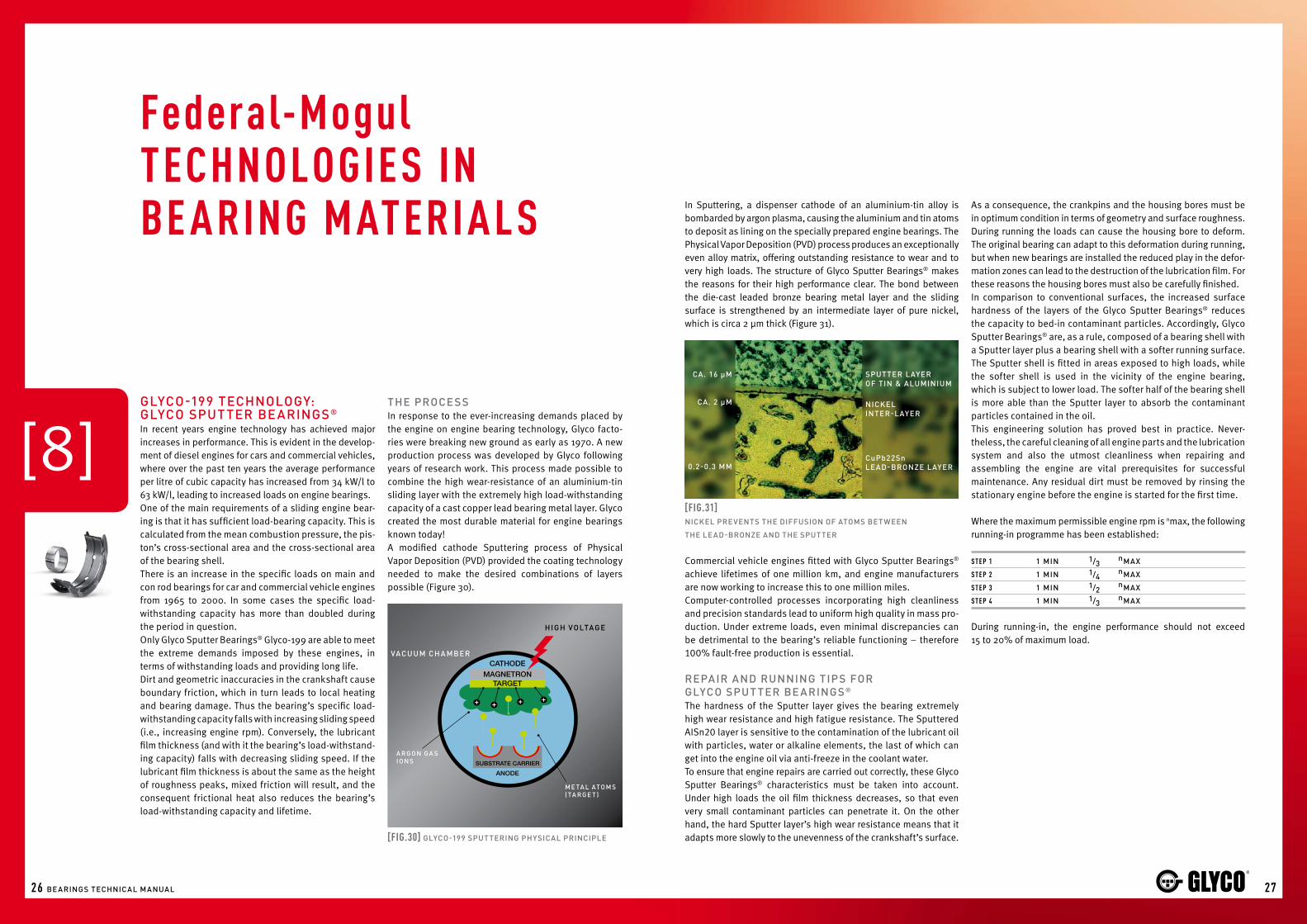
In Sputtering, a dispenser cathode of an aluminium-tin alloy is bombarded by argon plasma, causing the aluminium and tin atoms to deposit as lining on the specially prepared engine bearings. The Physical Vapor Deposition (PVD) process produces an exceptionally even alloy matrix, offering outstanding resistance to wear and to very high loads. The structure of Glyco Sputter Bearings® makes the reasons for their high performance clear. The bond between the die-cast leaded bronze bearing metal layer and the sliding surface is strengthened by an intermediate layer of pure nickel, which is circa 2 μm thick (Figure 31).
[Fig.31]nickel prevenTs The diffusiOn Of aTOMs BeTween
The lead-BrOnze and The spuTTer
Commercial vehicle engines fitted with Glyco Sputter Bearings® achieve lifetimes of one million km, and engine manufacturers are now working to increase this to one million miles.Computer-controlled processes incorporating high cleanliness and precision standards lead to uniform high quality in mass pro-duction. Under extreme loads, even minimal discrepancies can be detrimental to the bearing’s reliable functioning – therefore 100% fault-free production is essential. repair and running Tips fOrglycO spuT Ter Be arings®
The hardness of the Sputter layer gives the bearing extremely high wear resistance and high fatigue resistance. The Sputtered AISn20 layer is sensitive to the contamination of the lubricant oil with particles, water or alkaline elements, the last of which can get into the engine oil via anti-freeze in the coolant water.To ensure that engine repairs are carried out correctly, these Glyco Sputter Bearings® characteristics must be taken into account. Under high loads the oil film thickness decreases, so that even very small contaminant particles can penetrate it. On the other hand, the hard Sputter layer’s high wear resistance means that it adapts more slowly to the unevenness of the crankshaft’s surface.
As a consequence, the crankpins and the housing bores must be in optimum condition in terms of geometry and surface roughness.During running the loads can cause the housing bore to deform. The original bearing can adapt to this deformation during running, but when new bearings are installed the reduced play in the defor-mation zones can lead to the destruction of the lubrication film. For these reasons the housing bores must also be carefully finished.In comparison to conventional surfaces, the increased surface hardness of the layers of the Glyco Sputter Bearings® reduces the capacity to bed-in contaminant particles. Accordingly, Glyco Sputter Bearings® are, as a rule, composed of a bearing shell with a Sputter layer plus a bearing shell with a softer running surface.The Sputter shell is fitted in areas exposed to high loads, while the softer shell is used in the vicinity of the engine bearing, which is subject to lower load. The softer half of the bearing shell is more able than the Sputter layer to absorb the contaminant particles contained in the oil.This engineering solution has proved best in practice. Never-theless, the careful cleaning of all engine parts and the lubrication system and also the utmost cleanliness when repairing and assembling the engine are vital prerequisites for successful maintenance. Any residual dirt must be removed by rinsing the stationary engine before the engine is started for the first time.
Where the maximum permissible engine rpm is nmax, the following running-in programme has been established:
st E p 1 1 Min 1/3 nMax
st E p 2 1 Min 1/4 nMax
st E p 3 1 Min 1/2 nMax
st E p 4 1 Min 1/3 nMax
During running-in, the engine performance should not exceed 15 to 20% of maximum load.

2928 Bearings Technical Manual
lead-free Bushes & Bearingsne w legisl aTiOn reQuireMenTsEvery year, end of life vehicles generate between 8 and 9 million tones of waste in the European Union which should be managed correctly. In 1997, the European Commission adopted a Proposal for a Directive which aims at making vehicle dismantling and recycling more environmentally friendly, sets clear quantified targets for reuse, recycling and recovery of vehicles and their components and pushes producers to manufacture new vehicles also with a view to their recyclability.
The legislation covering the use of lead was officially adopted in September 2000 and thousands of automotive businesses – from vehicle manufacturers to engine rebuilders – are impacted by the European Union’s End of Life Directive (2000/53/EC) that bans lead. The law, which came into effect on 1st July 2003, initially provided an indefinite exemption of bearings used in engine, transmission and drive train systems. This exemption was later amended and is now expected to end in 2011.
federal-Mogul cOMMiTMenT TO The envirOnMenTThanks to the special efforts of our Research & Development departments, Federal-Mogul already is the most advanced lead-free company in 2008. Federal-Mogul is ready to provide reliable and performing lead-free materials to fulfill the EU directive and achieve the required engine performance demanded by today’s automotive industry. This clearly shows our commitment to in-novation and to the environment. Federal-Mogul’s leadership is once more proven, and we continue to be first in the market with the best available bearing materials.Although leaded replacement bearings for old vehicles (but not for new ones) can be supplied after the next legislation deadline, Federal-Mogul is independently committed to environmentally friendly manufacturing. Whenever technically possible, we will go further than new legislation and we have made it our goal to eliminate lead from the manufacture of all bearings and bushes.
le ad-free MaTerial s Through world-class expertise in design, metallurgy and manu-facturing, Federal-Mogul works with OE customers to develop materials to meet the requirements of new legislation, while al-lowing engines to deliver maximum performance, lower pollution and use less harmful materials.
Now, Federal-Mogul Research & Development has created lead-free bushes and bearings. The several new patented technologies are already used by many OE manufactures and will be the base to allow compliance to new EU directives and to achieve the required modern engine outputs produced today and in the future.Examples of some of these new patented technologies:
• LF-4, LF-5, LF-8 and RC-9 bronze bushings materials• G-444 and G-488 lead-free overlays
(unique Federal-Mogul MSA bath technology)• New G-499 Sputter and new RVD G-469
(Rapid Vapor Deposition)• Innovative aluminium bearing technology:
A-273, A-370, A-480, and A-590 bearing materials• Advanced manufacturing concepts • New boring technology• Laser welding
For over 100 years, Glyco has been the leading supplier of engine bearings. Thanks to our advanced material developments and manufacturing mastery, our leadership continues in this new lead-free era. Glyco has set new standards and has become the benchmark on new bearing materials. This is why Glyco is the supplier of choice for most OE manufacturers.
glycO lead-free TechnOlOgy: a-370® & cs-4Federal-Mogul has become leader with its exclusive new Glyco A-370 lead-free patented material as it provides the highest perfor-mance with very high resistance to fatigue and good adaptability. Furthermore, we have developed the bearing bronze alloy CS-4, a lead-free alloy that is not compromised by impurities. CS-4 is used as a substrate to make the new G-444 and G-488 overlay materials, created with a new and unique Federal-Mogul bath technology. CS-4 is also used in the newest generation of Glyco Sputter Bearings®, now developed into lead-free innovate ones, called G-469 and G-499.
Normally, copper alloys contain lead. While developing and re-searching lead-free solutions, Federal-Mogul has worked hard on creating lead-free bronze alloys. This is why: without the pres-ence of lead, copper alloys tend to harden. When impurities like metal powder are mixed in, bearings made of such an alloy will not change shape, and foreign matter may get into the bearing. By improving materials and fabrication methods, the hardness of the bronze CS-4 alloy is very close to that of a lead-copper alloy.
Tin & aluMiniuM
pure aluMiniuMinTer-layer
sTeel Back
[ F i g.32]crOss-secTiOnal cuT ThrOugh a Bearing shell Made Of a370®.
The pure aluMiniuM inTer-layer BOnds The Tin-aluMiniuM
OnTO The sTeel Back.
Machining specificaTiOns fOr The ne w federal-Mogul seMi-finished Bushe sOf aluMiniuM allOys
Boring of AISn20 alloy materials
Machining parameter recommendationCutting speed: vc = 500 m/minInfeed: ≈ 0,1 mm/revolutionExpected roughness: ≈ Rz 4 – 5 μm
PCD* cutting inserts recommendation
Basic shape: 55°Relief angle: 7°Corner radius: 0,4 mmMax. tip temperature: 600°C• Use PCD cutting insert according to alike geometry.• Geometry may vary due to individual machining equipment.• 1-2 drops of low viscosity oil per piece will improve machining.• Overheating of tip temperature will destroy PCD-structure
immediately.
* PCD - Poly Cristalline Diamond

3130 Bearings Technical Manual
glycO-188 TechnOlOgyprinciples and advanTagesIn recent years, the requirements on engine bearing materials have increased in two ways: firstly, the elimination of lead (in ad-dition to other white metals) will become more and more a future legal requirement. Secondly, the performance specifications of modern cars continue to increase.The development of modern initial combustion engines has led to performance increases. At the same time, engine dimensions, masses and parts are reducing. The smaller dimensions of sliding engine bearings increase the loads on them. Lightweight engine parts result in greater deformation of the con rod and engine block and this, in turn, puts further loading on the bearings. Consequently conventional tin-aluminium or leaded bronze bearings have often not continued to be developed.The famous Glyco Sputter Bearings® are a solution developed by Federal-Mogul. These bearings are capable of withstanding even the highest loads, however their disadvantage is the high production costs involved with the technology. The durability of Glyco Sputter Bearings® (technical term: Glyco-199) is twice as long as a conventional bearing. Federal-Mogul’s development centre in Wiesbaden consequently worked on closing this gap, the result being the new sliding bearings material Glyco-188. The layer structure of this material (Figure 34): a bronze and a tin-nickel layer are applied to a steel spine. An intervening nickel layer between the other two layers avoids the diffusion of tin atoms into the bronze layer.As a result of new production methods, it is now possible to add a further layer to the material consisting of tin and copper. Thanks to the copper, the otherwise relatively soft Sn-matrix becomes hardened.The tin-copper layer is still relatively soft during the engine’s initial running-in phase and adapts itself well to the surface structure of the crankshaft. The diffusion process is strengthened by thermal demands encountered during the running of the engine. Over time, the diffusion of nickel atoms from the nickel intervening layer and the tin atoms from the tin-copper layer result in the growth of the tin-nickel layer (Figure 33). This layer becomes durable and fatigue resistant as a result of the copper deposit of
the tin-copper layer concentrating itself on the tin-copper layer that had thinned.
glycO-18 8 is The fir s T “inTelligenT ” Be a ring M aTeri a l
sOf T during T he running-in ph a se
h a rd ThrOughOu T The re s T Of iT s l ife-TiMe
resulTs With Glyco-188, Federal-Mogul has developed a bearing mate-rial, which is capable of resisting very high loads.This new material offers good adaptability and bedding-in prop-erties, whilst meeting the need to be lead-free. The problems of high loads generating greater deformations are optimally and safely controlled through the hardening process which occurs naturally during the running of the engine.
unlOa ded a re a (ne a r T he pa r Ting line s) lOa ded a re a (ne a r T he crOw n)
[Fig.33] changE oF thE layEr systEm oF glyco-188: diFFusion oF atoms incrEasEs thE thicknEss oF thE tin-nickEl layEr.
BefOre afTer
T+P
SnNi
SnNi
π-SnCu (~SnCu40)
Sn
Ni
Ni
sOfT sn-MaTrix wiTh
hard eMBeddings.
under TherMal lOad,
The Thickness Of The
snni-layer increases
ThrOugh TransfOrMa-
TiOn Of The ni- and The
sn-layer.
The lOad-carrying
capaBiliTy increases
as The head parTicles
cOncenTraTe under-
neaTh The surface.
aT The saMe TiMe, The
Thickness Of The slid-
ing layer decreases.
[Fig.34] glyco-188 procEss oF changing
engine Bearings Oper aTe in a BruTal envirOnMenT. wiTh a BrOad r ange Of engine
Oper aTing speeds, TeMper aTures and OTher par aMeTers, These viTal cOMpOnenTs
are called On TO prOTecT The crankshafT and engine BlOck frOM preMaTure wear and
caTasTrOphic daMage.
TO wear is, in facT, whaT Bearings are expecTed TO dO, very gradually, Over MilliOns Of
engine revOluTiOns and ThOusands Of Miles. BuT prOTecTing The Bearings TheMselves frOM
acceleraTed wear is The JOB Of The engine reBuilder, whO MusT ensure ThaT The engine is
free Of dirT and deBris and ThaT all apprOpriaTe inTernal TOlerances are MainTained.
dirT is The engine Be aring’s MOsT cOMMOn eneMy. in facT, MOsT preMaTure Be aring
we ar can Be Tr aced TO dirT parTicles in The luBricaTing Oil. ThaT’s why The reMOval
Of cOnTaMinaTiOn ThrOughOuT The engine repair prOcess is criTical.
a QualiTy reBuilding JOB alsO reQuires sTricT aTTenTiOn TO inTernal OperaTing TOler-
ances. diMensiOnal and shape variances in The crankshafT JOurnals, MaTing surfaces
and hOusing BOres can cause iMMediaTe and severe daMage TO a reBuilT engine.
TO ensure The QualiTy Of any reBuild, The Technician alsO shOuld carefully dOcuMenT
in wriTing each sTep Of The repair. if a suBseQuenT QuesTiOn Or reliaBiliTy issue arises,
This recOrd Of The repair prOcess can serve as an invaluaBle guide in idenTifying and
eliMinaTing any prOBleM.
conclusion
Important: Claims for damages, of any form whatsoever, resulting from details made in this brochure or from incorrect use, application, storage or handling, are explicitly excluded. This brochure is not an operating manual for the use and installation of the bearings. It does not contain any advice in a legal sense. The brochure neither replaces the constantly applicable technical regulations – particularly for tolerances – nor the installation and maintenance stipulations of the individual engine manufacturer. Also, it is not possible to forego the expertise of those carrying out the installation and application. The individual references made in this brochure for the installation and the application of the bearings are instructions solely for the technically qualified specialists and are to be checked and verified by him for their suitability in each case. Federal-Mogul/GLYCO accepts no responsibility for application decisions.
Reproduction of this brochure of parts hereof is only allowed with our explicit permission in writing. Pictorial representations and design are copyrighted. The right is retained to correct errors and alterations.

Federal-Mogul Corporation • Central Distribution CentrePrins Boudewijnlaan 7 • B-2550 Kontich • Belgium • Tel: +32 (0)3 450 83 10 • Fax: +32 (0)3 450 83 38
Federal-mogul advancEd anti-countErFEit programmE
pErmanEntsElF-adhEsivE labElSeals the box with label detail on the frontlook For thE holospot®
The Holospot® label features a 4-digit alphanumeric code. Please check it to make sure that:• The4-digitcodeappearsinrainbow
colours using the light of the magnifier and is different on each pack
• TheFederal-Mogullogoalsoappearsin the Holospot®. The last 4 digits of the alphanumeric code have to be the same as the ones in the Holospot®
crash lock box bottomPrevents any attempt to remove or exchange items as it is impossible to reseal once opened
chEck thE uniquE codE onlinE at www.fmecat.euEachFederal-Mogulparthasauniquecodewhichisdisplayed onthelabelsinanalphanumericandDataMatrixformat. ADataMatrixcodeisa2-dimensional(2-D)matrixbarcode. TheUniqueCodecanbeverifiedin3differentways:• TypingintheUniqueCode• Readingthe2-Dcodewitha2-Dscanner• Readingthe2-Dcodewithamobilephonewhichis
supportedbyNeoReader™(www.neoreader.com)Forfurtherdetailspleasecheckwww.fmecat.eu
protEctionSpecial label design means any attempt to remove or swap the label will result in tearing
The following features on all NEW ENGINE packaging prove that the parts inside are Original Quality.
1
2
3
4
5
Verify the Unique Code online at www.fmecat.eu
PRM
GY1
000-
EN