evaluation of transient pin-stress requirements for … of transient pin-stress requirements for...
TRANSCRIPT

Evaluation of transient pin-stress requirements for
spacecraft launching in Lightning environments. Pain Free Analysis to alleviate those Pin Stress Headaches
Paul Edwards
Kennedy Space Center
ai-Solutions
KSC, USA
Alex Terseck
Kennedy Space Center
ai-Solutions
KSC, USA
Dawn Trout
Kennedy Space Center
NASA
KSC, USA
Abstract— Spacecraft are generally protected from direct
lightning attachment by encapsulation within the payload fairing
of a launch vehicle and the ground structures that exist at the
launch site. Regardless of where lightning strikes, potentially
damaging indirect effects prevail from the coupling of
electromagnetic fields into a loop created by outer shield of the
payload umbilical. The energy coupled into individual spacecraft
circuits is dependent on the umbilical current drive, the cable
transfer impedance and the source/ load circuitry, and the
reference potential used. Lightning induced transient
susceptibility of the spacecraft avionics needs to be fully
understood in order to define realistic re-test criteria in the event
of a lightning occurrence during the launch campaign. Use of
standards such as RTCA/DO-160 & SAE 5412 has some
applicability but do not represent the indirect environment
adequately. This paper evaluates the launch pad environments,
the measurement data available, and computer simulations to
provide pain-free analysis to alleviate the transient pin-stress
headaches for spacecraft launching in Lightning environments.
Keywords— induced transient effects; lightning coupling; re-
test criteria; spacecraft; launch complex; transmission line matrix
method;
I. INTRODUCTION
Each launch vehicle contractor uses a systemic approach for the mitigation and protection of their expendable/re-usable launch vehicle (ELV) from lightning environment effects. Launch processing constraints (weather FX), Launch Pad Lightning protection & monitoring systems such as; Wire catenary or Towered Down conductors, serve to protect from direct attachment and redirect the lightning channel away from the ELV. Traditional robust EMC countermeasures are employed such as cable bundle shielding, bonding & grounding and robust transient suppression devices in all avionic sub-system boxes that have a cable interface with other internal and external sub-systems.
Comparing vehicle operational lifecycles; Spacecraft requirements typically consider the electromagnetic environments for where it’s going and not so much where it’s from. Probability studies aside, the risk of exposure to a lightning environment is dependent on: launch site geographical location, date of intended launch, prevailing
weather patterns and if lightning occurs during operations at the pad; the variability of strike magnitude & proximity to the launch pad and attachment to launch service provider lightning protection systems, reduces the risk substantially. Standards would require system countermeasures to withstand effects from a 200kA, but with probability of strike occurrence with this magnitude virtually zero, it is understandable why spacecraft do not consider lightning transient protection as part of system EMI control planning, not to mention additional cost of design, verification and validation.
Despite the Odds - Lightning strikes do occur during launch processing. Once encapsulated inside the launch vehicle and under the protective infrastructure provided at the launch pad, spacecraft is at risk from indirect effects inherent with external cable connection between the launch vehicle and remote electrical ground support equipment (EGSE). With systemic levels of protection and monitoring systems in place, how does spacecraft evaluate the integrated susceptibility / damage risk to critical flight hardware and numerate its own policy for system retest decisions.
This paper identifies a worst case risk scenario for spacecraft; presents traditional BoE analysis using simple calculations, 3D simulation to anchor the lightning coupling model. Using CST cable studio [1] we evaluate strike induced shield current coupling to internal wire pairs through cable transfer impedance. Common-mode and differential mode coupling is also evaluated to demonstrate transient pin-stress levels from known shield currents, and typical spacecraft interface circuitry is evaluated. Finally, we show that interface susceptibility requirements can be derived from site specific, measured loop current and characterized umbilical cable transfer impedance. Spacecraft can use these requirements to evaluate interface circuit susceptibility versus the magnitude of measured loop current, and numerate damage threshold and upset level tolerance for re-test criteria.
II. SPACECRAFT LIGHTNING RISK SCENARIO
A. Spacecraft integrated with launch vehicle at Launch Pad
An integrated Spacecraft are most at risk from lightning events during pre-launch operations at the pad, and connected via long umbilical cables between launch vehicle/spacecraft.
https://ntrs.nasa.gov/search.jsp?R=20160007493 2018-06-01T05:49:11+00:00Z

Direct attachment of lightning to the launch vehicle is an unlikely scenario, prevented by the lightning catenary/down conductor system in place. However, strike attachment to the catenary or earth ground nearby, will result in radiated electromagnetic fields that indirectly couple currents into spacecraft circuits. This risk scenario is shown in Figure 1.
B. Spacecraft encapsulated during transport
Encapsulated inside the payload fairing, spacecraft are often transported over ground from a spacecraft processing facility to the launch pad for final assembly. During transport lightning could occur, creating a scenario for direct attachment to a composite structure. While the spacecraft would be in an electrically inert state, latent damage may be possible due to indirect effects coupling to internal spacecraft cables. If lightning conditions were forecast, the responsible payload safety team would likely delay transport until conditions improved.
III. STANDARDS APPLICABILITY
Although there is still some disparity on the specified lightning waveforms, the general practice of the space community has merged to the component A waveform given in (1) and specified in MIL-STD-464 and AIAA S-121 [2,3]. There is significant variance, however, in how or even if box level lightning immunity is implemented. Historically, in documents such as MIL-STD-1541 and Mil-E-6051 lighting was treated as a system problem [4,5]. With more digital equipment, the need to address lightning consistently at the box level emerged. RTCA-DO-160 is perhaps the longest standing recognized authority on box level testing for equipment immunity to indirect and direct lighting effects for aircraft [6]. Here tests are provided for cable bundle and pin injection with waveforms specific to the equipment location and vehicle housing (metal or composite) and levels ranging from protected to severe. Some launch vehicle providers test to this standard for vehicle avionics, while other providers use some combination of testing that is in MIL-STD-461. The latest version of this document has a CS117 test for lightning induced transients; however, examination of the applicability
matrix shows only limited application even in the military realm. So, what is a sensitive spacecraft to do when faced with a plethora of choices of tests that are typically more severe than the general electromagnetic tests required? First, it is important to differentiate between indirect lightning effects and the effects from nearby lightning strikes. In the case of indirect, the hardware being tested is in a vehicle that has the potential to have a direct strike, but the hardware itself is not directly exposed to these direct effects. Indirect effects’ testing is applicable for space systems when the ground facility hardware does not adequately protect the launch vehicle from a direct strike current. Nearby effects are the induced currents and voltages from a nearby strike. MIL-STD-461 states that the damped sine and exponential transient tests [7], CS115 and CS116 are more applicable for nearby lightning induced effects specified in MIL-STD-464. The rate of change at 10 meters from a near strike is specified at 2.2x10⁹ A/m/s for the magnetic field and 6.8x10¹¹ V/m/s for the electric field. CS115 is applied to the cable bundle and CS116 is applied to the bundle and power lines. For guidance and comparison, this paper provides simulation of pin effects induced by nearby strikes and strikes to the lightning protection system.
IV. INDIRECT EFFECTS – TRANSFER FUNCTION
The electromagnetic transfer function between an actual lightning strike at the pad and transients that may appear on spacecraft circuits is complex and dependent on so many variables, such as but not limited to: Characteristics of Site lightning protection system (LPS) facilities (Catenary/Down Conductor), Strike location (Ground/LPS) Distance, Azimuth to plane of Umbilical loop, Shielding effects of other structures, Cable construction, bonding & grounding and Structural Ground Return effects. These uncertainties make it difficult to provide spacecraft with any rational, analysis parameters to determine their own susceptibility.
In a companion paper [8], Terseck & Trout examined worst case coupling into a simple umbilical loop, relative to the site specific variables above. Using umbilical shield current as the measure, their study showed that traditional analysis was an effective predictor of the worst case bound, but due to the variable effects and uncertainties in this large scale electromagnetic coupling problem, the predictions were overly conservative when compared to Range / OLMS measured data and CST simulations.
In review, the spacecraft umbilical is launch site specific, but constant in cable construction and routing. In traditional analysis, Loop area and cable shield length are fixed variables used in the transfer function between EM fields and resultant umbilical shield current. This suggests that the pin-stress problem can be decoupled from the uncertainties of the external environment to the simpler measure of umbilical current.
V. TRADITIONAL PIN-STRESS ANALYSIS
In Fig 1, we show direct attachment of a 200kA strike (return stroke peak current) to the catenary system. The tower is 64m away. For simplification we will assume a straight conductor to ground and the resulting radiated magnetic field
Identify applicable sponsor/s here. If no sponsors, delete this text box (sponsors).
Figure 1 – Lightning Risk Scenario – Catenary Tower Attach

vector normal to the vertical plane of the loop created by the umbilical cable, the launch vehicle and reference plane.
The analysis approach [9] is described in Figure 2.
A. Umbilical current – Electromagnetic Coupling
Component A, MIL-STD 464 is typically used as the source lightning current and has a double exponential waveform form:
𝐼𝐶𝑜𝑚𝑝𝐴(𝑡) = 𝐼0(𝑒−𝛼𝑡 − 𝑒−𝛽𝑡) (1)
𝛿𝐼(𝑡)
𝛿𝑡= 𝐼0(−𝛼𝑒−𝛼𝑡 + 𝛽𝑒−𝛽𝑡) (2)
Where: 𝐼0 = 218810 𝐴 , fall 𝛼 = 11354 𝑠−1 and rise
𝛽 = 647265𝑠−1
Calculate magnetic field (B) Tesla at radial distance (r) meters from the strike (Biot- Savart):
�̂�(𝑡) =𝜇0𝐼0(𝑡)
2𝜋𝑟∙ �̂� =
𝜇𝐼
2𝜋𝑟 (3)
Where �̂� = Unit field vector component, assumed 1
The open circuit induced voltage (Voc) due to time-varying
magnetic flux is:
𝑉𝑜𝑐(𝑡) = −𝑑𝜙
𝑑𝑡= − ∬
𝑑𝐵
𝑑𝑡∙ �̂�
𝑙𝑜𝑜𝑝∙ 𝑑𝐴 = −
𝐵∙𝐴
𝑑𝑡 (4)
Where B and �̂� is the unit vector (1) normal to the surface area
(A) of the umbilical loop. The incident flux induces an emf
(Voc) to drive current in the conductor loop. The loop current
(Iloop) resolves to:
𝐼𝑙𝑜𝑜𝑝(𝑡) = −1
𝑍𝑙𝑜𝑜𝑝∫ 𝑉𝑜𝑐 𝑑𝑡 = −
𝐵∙𝐴
𝑍𝑙𝑜𝑜𝑝 (5)
Where Zloop is the total loop impedance and equal to the sum
of Zshield, ZLV and Zgnd. These variables are site specific and
require knowledge of: cable construction, geometry, physical
layout and grounding; LV construction (materials, joints,
bonds) and physical geometry and physical geometry between
earth grounding points to estimate individual impedances.
However, combining equations 3& 4 we find:
𝑉𝑜𝑐 = −𝜇0𝐼0𝐴
2𝜋𝑟∙𝑑𝑡 (6)
Where dt is the Component A, pulse rise time dt = 6.4μs
With 𝐼0 = 218810 𝐴𝑚𝑝𝑠 the resultant Voc is calculated to be: 16026 Volts
Umbilical shield current can be evaluated if Zloop, is known:
Using the “universal answer” [10], let Zloop = 42 Ohms
Iloop calculates to be: 16026/42 = 381 Amps
With an umbilical shield current established for the worst case lightning occurrence coupling into the launch site specific cable geometry, we can determine transient pin-stress levels.
B. Cable Transfer Impedance
Transfer impedance (ZT) relates the current flowing on shield outer surface to the longitudinal voltage developed by current diffusion to the inner surface. This voltage couples in turn to internal conductors and impresses a transient stress voltage onto the input terminals of victim circuits. Shield Transfer Impedance (Zt) is:
𝑍𝑡𝑟𝑎𝑛𝑠𝑓𝑒𝑟 = 𝑉𝑖𝑛𝑡𝑒𝑟𝑛𝑎𝑙
𝐼𝑙𝑜𝑜𝑝 , Ohms/m (7)
Where Ztransfer is the shield dc resistance and the mutual inductance between shield and inner conductor(s).
Transfer impedance is not typically measured by cable manufacturers. It can be measured, but with cable bundles containing many conductor pairs, launch service contractors are loath to measure installed cables for reasons of time & cost.
Typical copper braided shields have a transfer impedance 1-50mOhm/m [11] - Use 10mOhm/m
C. Pin Stress – Common Mode
The umbilical shield terminates at the body of the launch vehicle with a shielded connector interface. Signal cables continue through the LV interface to internally to connect with spacecraft at the separation interface.
Based on any coupled shield current, common mode stress voltage can be calculated over the length of the umbilical.
𝑉𝑐𝑚 = 𝐼𝑙𝑜𝑜𝑝 ∙ 𝑍𝑡𝑟𝑎𝑛𝑠𝑓𝑒𝑟 ∙ 𝑙𝑒𝑛𝑔𝑡ℎ (7)
The resultant Vcm = 333*0.010*53 = 176.9 Volts. This is for a single conductor internal to a single shield.
D. Pin Stress – Worst case reduction
With open circuit voltage calculated for a single conductor, this worst case number can be reduced using the assumption that energy transfer will be shared “equally” between the number of conductors enclosed by the shield. There is also a general assumption that there will be common to differential mode attenuation of ~ 40dB
Figure 2 – Analysis Approach – Spacecraft Pin Stress

VI. SIMULATION ANALYSIS
Predicting spacecraft interface circuit behavior during a lightning strike can be very difficult when the data provided is taken from the strike event itself. Using values of strike magnitude and distance as a basis for traditional analysis can be time consuming and riddled with uncertainties. This is can cause real stress headaches when a mission go/no go re-test decision is required.
Instead we propose utilization of historical data from the umbilical current monitors existing at each launch site to provide a foundation upon which to characterize each installation and provide a real-time measurement basis for future spacecraft retest criteria, using just umbilical current.
The models used in this paper do not simulate a nearby lightning strike every time, instead a source current is driven onto the outer shield of the cable bundle, and the pin stress voltages on inner conductors is simulated .
The source current waveform was generated in CST from a simulated vertical lightning channel 64m away from the launch vehicle and coupled into a 150m
2 umbilical loop. This
simplified model simulated an attachment to one of the catenary towers with the LV underneath as in Figure 1, but the tower was assumed to be straight conductor to ground as in the traditional analysis. See Figure 3
Comparison CST to traditional analysis :
The open circuit induced voltage (Voc) due to time-varying magnetic flux is: 16026 Volts (Trad) vs 16822 Volts (CST)
In the following sections we demonstrate the practical use of umbilical current sources to
A. Umbilical Current Magnitude vs Common Mode Voc
Using a simple cable construction; single 22AWG shielded twisted pair with drain wire, with an outer shield. Each conductor 50 ohm terminated at one end, and open circuit (1GOhm termination) the other end. Transfer Resistance = 0.010 Ohm/m, Transfer Inductance = 1.0E-9 H/m, Cable length 53m long. These parameters remain constant unless otherwise stated.
A current waveform generated from our seed 3D coupling model was manipulated to create injection currents of different magnitudes and rise times to meet component A. The experiment is shown in Figure 4, with a representative graphical result for 1200 A.
This model was also run with an additional outer shield as part of the cable construction. This double shielding of internal STP conductors was representative of some site installations.
TABLE I. SHIELD CURRENT MAGNITUDE VS INTERNAL CONDUCTOR
OPEN CIRCUIT VOLTAGE
Current Magnitude vs Conductor Open Circuit Voltage
Umbilical Current Peak
(Amps)
Single Shield
Conductor Voc (Volts)
Double Shield
Conductor Voc (Volts)
1200 A 534 V 352 V
400 A 178 V 117 V
100 A 42 V 29 V
20 A 9 V 6 V
5 A 2.2 V 1.4 V
0.5 A 0.22 V 0.14 V
This data comes from our example 200kA strike, 64m away from a 150m
2 umbilical loop. From OLMS site data, umbilical
Figure 3 – Simulated 200kA lightning strike into 150m2 Loop
Figure 5 – Umbilical Magnitudes versus Conductor Voc – 1 TWSP in
Single Overbraid
Figure 4 –External loop Transient Voc
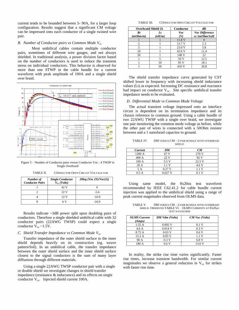
current tends to be bounded between 5- 90A, for a larger loop configuration. Results suggest that a significant CM voltage can be impressed onto each conductor of a single twisted wire pair.
B. Number of Conductor pairs vs Common Mode Voc
Most umbilical cables contain multiple conductor pairs, sometimes of different wire gauges, and not always shielded. In traditional analysis, a power division factor based on the number of conductors is used to reduce the transient stress on individual conductors. This behavior is observed for more than one STWP in the cable bundle for a current waveform with peak amplitude of 100A and a single shield over braid.
TABLE II. CONDUCTOR OPEN CIRCUIT VOLTAGE FOR
Number of Conductor Pairs
Single Conductor Voc (Volts)
20log (Voc (N)/Voc(1))
1 42 V 0
2 22 V -5.6
4 12 V -10.9
8 6 V -16.9
Results indicate ~3dB power split upon doubling pairs of conductors. Therefore a single shielded umbilical cable with 32 conductor pairs (22AWG TWSP) could expect a single conductor Voc ~1.5V.
C. Shield Transfer Impedance vs Common Mode Voc
Transfer impedance of the outer shield surface to the inner shield depends heavily on its construction (eg. weave pattern/foil). In an umbilical cable, the transfer impedance between the outer shield surface and the inner shield surface closest to the signal conductors is the sum of many layer diffusions through different materials.
Using a single 22AWG TWSP conductor pair with a single or double shield we investigate changes in shield transfer impedance (resistance & inductance) and its effects on single conductor Voc. Injected shield current 100A.
TABLE III. CONDUCTOR OPEN CIRCUIT VOLTAGE FOR
Overbraid Shield Zt Conductor dB
Rt
(mOhm/m)
Lt
(nH/m)
Voc
(V)
Voc Difference
vs 1mOhm/1nH
1 1 11.8 V 0
2 1 13.7 V 1.3
5 1 23.0 V 5.8
10 1 43.6 V 11.4
50 1 148 V 22
1 5 50 V 12.5
1 10 95 V 18.1
1 50 410 V 30.8
The shield transfer impedance curve generated by CST shifted lower in frequency with increasing shield inductance values (Lt) as expected. Increasing DC resistance and reactance had impact on conductor Voc. Site specific umbilical transfer impedance needs to be evaluated.
D. Differential Mode vs Common Mode Voltage
The actual transient voltage impressed onto an interface circuit is dependent on its termination impedance and its chassis reference to common ground. Using a cable bundle of two 22AWG TWSP with a single over braid, we investigate one pair monitoring the common mode voltage as before, while the other pair of wires is connected with a 50Ohm resistor between and a 1 nanofarad capacitor to ground.
TABLE IV. DM VERSUS CM – 2 PAIR BUNDLE WITH OVERBRAID
SHIELD
Current DM CM
1200 A 67 V 276 V
400 A 22 V 92 V
100 A 5.5 V 22.5 V
20 A 1.1 V 4.6 V
5 A 0.27 V 1.1 V
0.5 A 0.027 V 0.1 V
Using same model, the 8x20us test waveform recommended by IEEE C62.41.2 for cable bundle current injection was applied to the umbilical shield using a range of peak current magnitudes observed from OLMS data.
TABLE V. DM VERSUS CM – 2 PAIR BUNDLE WITH OVERBRAID
SHIELD OBSERVED TABLE VI. OLMS CURRENTS AT 8X20µS
TEST WAVEFORM
OLMS Current
(Amps)
DM Vdm (Volts) CM Voc (Volts)
1.55 A 0.005 V 0.1 V
4.6 A 0.014 V 0.3 V
8.75 A 0.03 V 0.6 V
15.3 A 0.05 V 1.1 V
90 A 0.3 V 6.8 V
180 A 0.6 V 13.6 V
In reality, the strike rise time varies significantly. Faster rise times, increase transient bandwidth. For similar current magnitudes we observe a general reduction in Voc for strikes with faster rise time.
Figure 5 – Number of Conductor pairs versus Conductor Voc - 4 TWSP in
Single Overbraid

E. DM vs CM – Internal Spacecraft Termination
The spacecraft is internal to the launch vehicle attached to and additional length of cable. This scenario has been simulated for an 8 pair cable terminated in DM & CM configurations (4 each).
F. Termination Impedance – Spacecraft Circuits
Spacecraft termination impedances have been simulated in a typical umbilical configuration. Using the 4 TWSP model with single over-braid and 100 Amp injected current, we basically model an interface with: +3.3V line driver output, + 5V line receiver input and a voltage input with a +2.4V reference level.
Based on the assumptions of the original 4TWSP model
these results demonstrate transient effects based on driven
umbilical current.
VII. CONCLUDING DISCUSSION & RECOMMENDATIONS
For every mission potential lightning transient coupling into spacecraft circuits requires a risk assessment which generally presents difficulties (headaches) for the program due to uncertainty surrounding lightning strike magnitude and occurrence and specification of adequate re-test criteria. At
each launch site, specific lighting protection systems exist to protect both launch vehicles and integrated payloads. Site monitoring systems (e.g OLMS) routinely measure lightning activity including the umbilical currents.
In this paper we have used simulation tools to investigate the use of site measured umbilical current as re-test decision criteria. Using basic, life size 3D models/Circuit co-simulation in CST Cable Studio [1] we have shown how driving current onto the umbilical shield provides insight into actual transient levels that could be experienced at the spacecraft interface.
Models are only as good as the input assumptions. Actual transient levels at the spacecraft interface vary based on the magnitude (Amps) and character (rise time) of shield current, the construction of umbilical, the transfer impedance (Ztransfer) and circuit termination impedances. Therefore, launch site specific characterization of installed umbilical cables and data analysis of measured umbilical current is recommended.
Fully characterized models that yield realistic EM coupled transient levels can be used to generate umbilical current based pin-stress waveform requirements. These can be used by a spacecraft program team, to assess interface susceptibility and numerate a threshold value of umbilical current to be used in system re-test criteria.
In conclusion - realization of “Pain Free Analysis to alleviate Pin Stress Headaches” is proved in concept however, we suggest keeping suitable medication on hand until the concept becomes reality.
ACKNOWLEDGMENTS
REFERENCES
[1] CST – Computer Simulation Technology AG, Bad Nauheimer Str. 19, 64289 Darmstadt, Germany
[2] Electromagnetic Environmental Effects Requirements for Systems, MIL-STD-464, Department of Defense, 1 Dec 2010.
[3] AIAA S-121-2009, EMC Requirements for Space Systems.
[4] MIL-STD-1541 EMC Requirements for Space Systems,Department of the Air Force,30 Dec 1987.
[5] MIL-E-6051D, Electromagnetic Requirements, Systems, Department of Defense, 7 sep 1967.
[6] RTCA-DO-160, Environmental Conditions and Test Procedures for Airborne Equipment
[7] Mil-Std-461, Requirements for the Control of Electromagnetic Interference Characteristics of Subsystems and Equipment, Department of Defense, 11 Dec 2015.
[8] Terseck A., Trout D, Investigation on Improvements in Lightning Retest Criteria for Spacecraft, ” IEEE International Symposium on EMC, July 24-29, 2016, Ottawa, Canada.
[9] F. A. Fisher, R.A. Perala, J. A. Plumer, Lightning Protection of Aircraft, Lightning Technologies Inc., 1990, pp. 258-259.
[10] Adams, D. The Hitchhiker's Guide to the Galaxy. New York: Harmony Books, 1980. Print
[11] L. O. Hoeft and J. S. Hofstra, "Measured electromagnetic shielding performance of commonly used cables and connectors," in IEEE Transactions on Electromagnetic Compatibility, vol. 30, no. 3, pp. 260-275, Aug 1988
Figure 6 – Internal Spacecraft terminations
Figure 7- Spacecraft Circuit Terminations