evaluation of the trc (textile reinforced concrete...
TRANSCRIPT

2nd International RILEM Conference on Strain Hardening Cementitious Composites 12-14 December 2011, Rio de Janeiro, Brazil
89
EVALUATION OF THE TRC (TEXTILE REINFORCED CONCRETE) SOLUTIONS IN THE CASE OF RC BEAMS SHEAR STRENGTHENING
R. Contamine P
(1)P, A. Si LarbiP
(1)P and P. Hamelin P
(1)
(1) Claude Bernard University of Lyon1 (France) Abstract
The objective of this study is to substitute carbon or glass fibber reinforced polymer
composite by glass mineral matrix composites in order to improve the shear behaviour of short beams. The conclusion consists in evaluating the degree of correlation between the experimental results and the guideline formulations, with the objective to eventually transpose them directly to the case of mineral matrix composites, and if necessary, the existing rules are amended by appropriate modifications. The result of this first experiment study on the efficiency of cement composite used for external shear strengthening of RC beam clearly enhance can be as reliable as usual FRP (Fibre Reinforced Plastic). The ultimate load compare to the reference specimen has shown it. On other hand the existing model are not able to predict correctly the ultimate shear load mainly because material mechanical law is different and because failure load may be modified in comparison with usual FRP material.
1. INTRODUCTION The main objective of this work is to evaluate the substitution of glass or carbon FRP by
cement based composite in the case of RC beam reinforced for shear purpose. Two cement based composite are consider in this study, the first one is made with an
inorganic matrix and glass fibber [1] reinforcement while the second one is made with a high performance cement matrix reinforced by short steel fibbers (UHPC). In order to evaluate the efficiency of these materials, a three point bending test is done. This test allows evaluating the maximal tensile force undertaken by the reinforcement. Results are compared with usual shear RC calculation French design method (BAEL 91)
It as possible to found a numerous parameter in literature that influence directly the behaviour of the reinforced element. The effect of the ratio between the distances of the applied load and the support (a/d) has been shown by Gynseon [2], Khalifa [3] and Bouselham [4]. These authors have shown the contribution of the composite is decreased if this ratio decrease, which could be explained by the load transfer directly from the applied load to the support.
The reinforcement on the entire section is difficult for technical reason, most of the study mention focus on beam side reinforcement with a U shape or just lateral plate bonding. In most of the case (Gyuson [2],Monti [5], Jayprakash [6], Talsjten [7]), the U shape solution is most effective thanks to a more important bonded length (Wu [8], Zhang [9]). Another

2nd International RILEM Conference on Strain Hardening Cementitious Composites 12-14 December 2011, Rio de Janeiro, Brazil
90
interesting parameter is the composite reinforcement fibber orientation, when these reinforcements are in the same direction than the concrete crack, the composite efficiency is increased.
With not enough result, the effect of the transverse steel reinforcement ratio as been evaluate by Li [10] and Bouselham [4]. These authors clearly enhance that the composite efficiency mainly depends on the transverse steel ratio. The more important it is, the less the force undertaken by the composite reinforcement is. At the end, Bouselham [4] has shown that the increase of reinforcement thickness generally do not increase in the same way the shear capacity of the reinforcement, concluding on the fact that there is an optimal axial stiffness of the reinforcement.
On design point of view, none of the numerous resign relation proposed in the literature allows to estimate correctly the shear capacity of these reinforcement if the result is compare with the entire data base available in literature. Most of the proposed relations are fitted for specific results (Khalifa [3], Lima [11], Chen [12], Bouselham [4]). The model actually proposed are based on superposition on material contribution, respectively a summation of concrete (Vc), steel (Vs) and composite reinforcement (Vf).
The hypothesis generally retains are the one of a Ritter Mörsh truss, the yielding of transverse steel rebars and generally a concrete cracking angle of 45°. Thus, two failure modes are considered for establishing analytical relation:
− The debonding of the interface between concrete and external bonded reinforcement
− Failure in tension of the reinforcement due to a macro-crack and local over stress in the reinforcement.
It is also important to outline the difference from a model to another is the limited design strength of the composite and the retained bonded length. These values are fitted from the experimental result in each case.
2. GENERAL SPECIFICATIONS
2.1 Specimen description In order to evaluate the shear efficiency of the reinforcement, the testing method proposed
by Wu [8] have been retained (Fig. 1).
Fig. 1: Samples descriptions
The concrete and properties of the concrete used of beam casting is given by table 1. Four specimens have been tested, the first one without any external reinforcement, the
three others reinforced respectively with external bonded CFRP, inorganic phosphate cement composite reinforced by glass fibers and high performance concrete reinforced with short steel fibers (Table 2 and Fig. 2).
3HA12
220
150 mm
HA6
600 mm
250 mm250 mm
50 mm 50 mm
194
2nd International RILEM Conference on Strain Hardening Cementitious Composites 12-14 December 2011, Rio de Janeiro, Brazil
91
Table 1: Concrete mix and properties
Cement CPA 52,5 (kg/m3) Water (l/m3)
Sand 0/4 (kg/m3)
Gravel 10/20 (kg/m3)
350 192 850 1020
Compression strength 33 MPa Tensile strength 2,3 MPa
Table 2 : Reinforcement material properties
CFRP Inorganic Phosphate cement (IPC)
High performance cement based
composite (UHPC) Tensile strength
[MPa] 925 40 12
Fibers UD Carbon 325 (g/m²)
Sheet 115 (g/m²)
2% in volume of metallic fiber
Young modulus of fibbers [MPa] 240 000 73 000 210 000
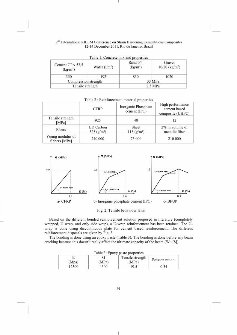
a- CFRP b- Inorganic phosphate cement (IPC) c- BFUP
Fig. 2: Tensile behaviour laws
Based on the different bonded reinforcement solution proposed in literature (completely
wrapped, U wrap, and only side wrap), a U-wrap reinforcement has been retained. The U-wrap is done using discontinuous plate for cement based reinforcement. The different reinforcement disposals are given by Fig. 3.
The bonding is done using an epoxy paste (Table 3). The bonding is done before any beam cracking because this doesn’t really affect the ultimate capacity of the beam (Wu [8]).
Table 3: Epoxy paste properties E
(Mpa) G
(MPa) Tensile strength
(MPa) Poisson ratio υ
12300 4500 19.5 0.34
σ (MPa) σ (MPa)σ (MPa)
ε (%) ε (%) ε (%)E= 80000 MPa
Ei= 14000 MPa
Ef= 4000 MPa
Ei= 50000 MPa
Ef= 13000 MPa925 40 13
1,1 0,6 0,3

2nd International RILEM Conference on Strain Hardening Cementitious Composites 12-14 December 2011, Rio de Janeiro, Brazil
92
Fig. 3: External reinforcement and strengthening details of beams specimens
2.2 LOADING DEVICE
A three point bending test has been retaining using a frame with a capacity of 500 kN (Fig. 4). The instrumentation have been done using displacement sensors (LVDT ± 5 mm) located at mid-pan and 120 Ω strain gauges located at mid high of transverse reinforcement rebars. The tests have been forced controlled until failure.
Fig. 4: Samples and instrumentation description
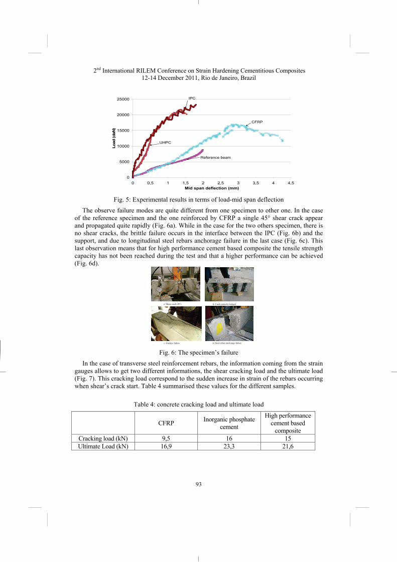
2.3 Experimental result The obtained result allows to observe an important increased of the ultimate load
comparing to CFRP reinforced specimen (168 kN) and the inorganic phosphate cement (IPC), (233 kN, + 39 %) or a high performance based composite (216 kN, +28%) which clearly enhanced the interest of such composite reinforcement.
It is also important to outline that there is an important increase of the bending stiffness and a tendency to obtain a brittle failure. Thus, one can observe that the relation between deflection and load is quite linear until failure for the two specimen reinforced with cement shear reinforcement. This can be explained by a more important axial stiffness of the plate reinforcement in comparison with the FRP.
54 mm54 mm 54 mm 54 mm
105 mm 105 mm 105 mm
132,5 mm
560 mm
Inorganic phosphate cement (IPC)
UHPC
1,2 mm
6 mm
15 mm
CFRP
LVDT ± 5 mm
Strain gauges (120 ohms)
220 mm
150 mm
600 mm
2nd International RILEM Conference on Strain Hardening Cementitious Composites 12-14 December 2011, Rio de Janeiro, Brazil
93
Fig. 5: Experimental results in terms of load-mid span deflection
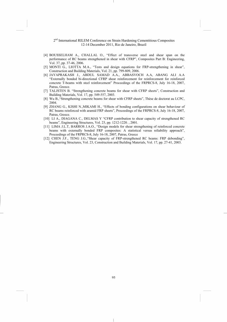
The observe failure modes are quite different from one specimen to other one. In the case of the reference specimen and the one reinforced by CFRP a single 45° shear crack appear and propagated quite rapidly (Fig. 6a). While in the case for the two others specimen, there is no shear cracks, the brittle failure occurs in the interface between the IPC (Fig. 6b) and the support, and due to longitudinal steel rebars anchorage failure in the last case (Fig. 6c). This last observation means that for high performance cement based composite the tensile strength capacity has not been reached during the test and that a higher performance can be achieved (Fig. 6d).
Fig. 6: The specimen’s failure
In the case of transverse steel reinforcement rebars, the information coming from the strain gauges allows to get two different informations, the shear cracking load and the ultimate load (Fig. 7). This cracking load correspond to the sudden increase in strain of the rebars occurring when shear’s crack start. Table 4 summarised these values for the different samples.
Table 4: concrete cracking load and ultimate load
CFRP Inorganic phosphate cement
High performance cement based
composite Cracking load (kN) 9,5 16 15 Ultimate Load (kN) 16,9 23,3 21,6
0
5000
10000
15000
20000
25000
0 0,5 1 1,5 2 2,5 3 3,5 4 4,5Mid span deflection (mm)
Load
(daN
)
Reference beam
CFRP
UHPC
IPC
a- Shear crack (45°) b- Crack partially bridged
c- Inteface failure d- Steel rebars anchorage failure

2nd International RILEM Conference on Strain Hardening Cementitious Composites 12-14 December 2011, Rio de Janeiro, Brazil
94
This allows concluding that the external bonded cement based reinforcement increased the cracking load by more than 50% while the external bonded CFRP do not modify the elastic behaviour of the RC beam. This also explains why the bending stiffness of the RC beam strengthened by cement based reinforcement is higher due to less micro shear cracks.
Fig. 7: Load-transverse rebars strains curve
3. CONCLUSIONS The results of this study, particularly the significant increase in carrying capacity and
bending stiffness, indicate that the use of new techniques of reinforcement based on mortar-based composite material would be advantageous.
Owing to the significant increase in the resistant section of the beam and to its partial confinement, U-shaped reinforced beams are shown to be systematically effective for the three used reinforcements, presenting very comparable performances in the case of the mortar-glass fibres composite and considerably greater in the cases of the inorganic phosphate cement-glass fibres and ultra high performances-shirt metallic fibres, which is explained by their performance, which is intrinsically and clearly superior to that of the mortar-glass fibres composite.
Although encouraging, the present study must be extended through a more significant database by considering the influence of such parameters as the ratio of steel rebars, the a/d ratio, the orientation of the reinforcement etc., and by undertaking numerical modelling to provide information on the mechanisms of shear failure and the shear force distribution along the cracks.
REFERENCES [1] CUYPERS H, WASTIELS J., “Stochastic matrix-cracking model for textile reinforced
cementitious composites under tensile loading”, Materials and structures, Vol. 39, 2005, pp. 777-786.
[2] GYUSEON K., JONGSUNG S., “Shear strength of strengthened RC beams with FRPs in shear”, Construction and Building Materials, article in press.
[3] KHALIFA A., NANNI A., “Improving shear capacity of existing RC T-section beams using CFRP composites”, Cement and Concrete Composites, Vol. 22, 1999 pp. 165-174.
0
5000
10000
15000
20000
25000
- 200 -100 0 100 200 300 400 500 600
S train ( �m/m)
Load
(da
N
Refe ren ce b ea m
CF RP
UHPC
I PC
2nd International RILEM Conference on Strain Hardening Cementitious Composites 12-14 December 2011, Rio de Janeiro, Brazil
95
[4] BOUSSELHAM A., CHALLAL O., “Effect of transverse steel and shear span on the performance of RC beams strengthened in shear with CFRP”, Composites Part B: Engineering, Vol. 37, pp. 37-46, 2006.
[5] MONTI G., LIOTTA M.A., “Tests and design equations for FRP-strengthening in shear”, Construction and Building Materials, Vol. 21, pp. 799-809, 2006.
[6] JAYAPRAKASH J., ABDUL SAMAD A.A., ABBASVOCH A.A, ABANG ALI A.A “Externally bonded bi-directional CFRP shear reinforcement for reinforcement for reinforced concrete T-beams with steel reinforcement” Proceedings of the FRPRCS-8, July 16-18, 2007, Patras, Greece.
[7] TALJSTEN B. “Strengthening concrete beams for shear with CFRP sheets”, Construction and Building Materials, Vol. 17, pp. 549-557, 2003.
[8] Wu B.,“Strengthening concrete beams for shear with CFRP sheets”, Thèse de doctorat au LCPC, 2004.
[9] ZHANG G., KISHI N.,MIKAMI H., “Effects of bonding configurations on shear behaviour of RC beams reinforced with aramid FRP sheets”, Proceedings of the FRPRCS-8, July 16-18, 2007, Patras, Greece.
[10] LI A., DIAGANA C., DELMAS Y “CFRP contribution to shear capacity of strengthened RC beams”, Engineering Structures, Vol. 23, pp. 1212-1220. , 2001.
[11] LIMA J.L.T, BARROS J.A.O., “Design models for shear strengthening of reinforced concrete beams with externally bonded FRP composites: A statistical versus reliability approach”, Proceedings of the FRPRCS-8, July 16-18, 2007, Patras, Greece
[12] CHEN J.F., TENG J.G.,“Shear capacity of FRP-strengthened RC beams: FRP debonding”, Engineering Structures, Vol. 23, Construction and Building Materials, Vol. 17, pp. 27-41, 2003.