evaluation of the rotor bar and end ring current waveform
TRANSCRIPT
Nkosinathi Gule, MIEEE and Maarten J. Kamper, SMIEEE E-mail: [email protected], [email protected]
Abstract— In this paper, a winding function theory based method of predicting the rotor bar and end ring current waveforms of a brush dc equivalent (BDCE) controlled cage rotor multi-phase induction machine is presented. Steady state analytically calculated and FEA results from an arbitrary chosen nine-phase induction machine are given. The analytical method is proved to useful in the performance evaluation of BDCE controlled multiphase induction machines.
I. INTRODUCTION
The multiphase induction machine drive has been under investigation for the last half century. Although it offers several attractive advantages over the conventional three-phase induction machine drive, it is restricted to highly specialised applications [1]. One aspect of the multiphase induction machine drive is the complexity of the control algorithm for decoupled flux and torque control. The complexity, arising from the required coordinate transformations, increases with increase in the number of phases of the machine. Recently, a method that allows the control of a six-phase induction machine drive without any coordinate transformations was developed and tested [2]. This new control technique allows the control of the machine to be similar to that of dc machines through the use of special trapezoidal-shaped stator current waveforms as shown in Fig. 1. These stator phase current waveforms consist of field (flux) and torque current components, with flat-topped amplitudes allowing a stator phase to act alternately in time as either a flux or a torque producing phase. The idea is to have a number of stator phases acting as flux producing phases, whilst the remaining phases act as torque producing phases at each time instance. The control method is proved to work remarkably well from practical measurements on both a wound rotor and a cage rotor induction machine drive [2-4]. Furthermore, the implementation of the BDCE control method is much simpler than the normal vector and direct torque control method. Due to its similarity to the control of brush dc machines, the control method is now called the “brush dc equivalent” (BDCE) control method.
It is known that the rotor bar and end ring current waveforms affects the performance of an induction machine. Also, a theoretical evaluation of the rotor bar and end ring current waveforms is needed in order to enhance the design process of BDCE controlled multiphase induction machines.
The instantaneous torque of the machine together with the rotor copper losses can then be calculated from the rotor bar and end ring current waveforms. Analysis of the machine in [2] is done by first assuming perfect commutation and quasi-square-wave air-gap flux density leading to an ideal square-like induced rotor phase current waveform (as shown in Fig. 2). Although the principle of operation of the induction machine drives in [2, 3], with the assumed quasi-square-like rotor current waveform, is proved to produce good measured results, it is necessary to theoretically evaluate the rotor bar and end ring current waveforms in order to enhance the understanding of the operation of BDCE controlled multiphase induction machines. Also, the instantaneous torque of the machine together with the rotor copper losses can then be calculated from the rotor bar and end ring current waveforms.
In this paper, an analytical method for predicting and evaluating the rotor bar and end ring current waveforms of a BDCE controlled cage rotor multi-phase induction machine is presented. The method is based on the application of the Fourier transform and winding function theory, developed in [5-7]. The winding function theory is used in the calculation of the mutual inductances between the stator and the rotor. Linear conditions are assumed. The method also allows for the calculation of the electromagnetic torque and rotor bar losses. Skin effect is considered in the calculation of the rotor bar
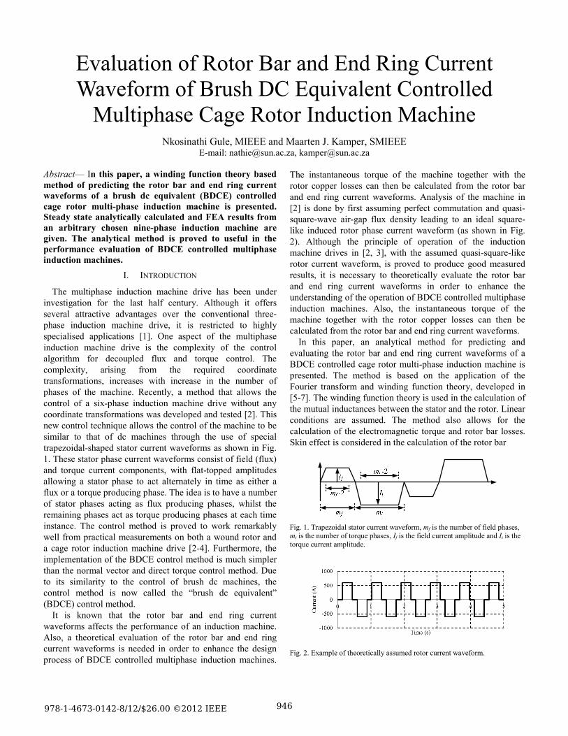
Fig. 1. Trapezoidal stator current waveform, mf is the number of field phases, mt is the number of torque phases, If is the field current amplitude and It is the torque current amplitude.
Fig. 2. Example of theoretically assumed rotor current waveform.
Evaluation of Rotor Bar and End Ring Current Waveform of Brush DC Equivalent Controlled
Multiphase Cage Rotor Induction Machine
978-1-4673-0142-8/12/$26.00 ©2012 IEEE 946
resistance of the machine. The developed algorithm is written in MATLAB and it allows the user to specify the machine’s; power, physical parameters, number of poles, number of phases, rated field and torque currents and rated speed. Due to the difficulty in measuring bar currents in cage rotors, the transient solvers of two commercially available finite element analysis (FEA) software packages (Maxwell2D and JMAG) are used to evaluate the theoretically calculated rotor bar and end ring current waveforms. Steady state theoretically calculated and FEA waveform results from an arbitrary chosen BDCE controlled nine-phase induction machine are given. The analytical method is simpler and can be used to quickly evaluate the performance of a BDCE controlled multiphase induction machine. The developed method can be expanded and used to evaluate the rotor current waveform of any multiphase induction machine supplied with any stator current waveforms.
II. BDCE CONTROL METHOD
In the BDCE control method, the stator current waveform is such that it produces separate rotating flux or field magneto-motive force (MMF) and torque MMF when applied to an appropriately wound stator winding. This is done such that, at each time instance, a group of consecutive phases act as field producing phases and the rest as torque producing phases. From this it can be seen that the moving rotating air-gap flux density waveform produced by the field producing phases is quasi-square like.
The flux produced by the field producing phases leads to induced voltages at slip speed in the rotor bars located under the torque phases. Then, the rotor phase currents will flow in the cage or shorted wound rotor winding under the torque phases and produce a flux in quadrature to the main flux. The torque current flowing in the torque phases must then produce a counter MMF to balance the MMF produced by the rotor current; this is similar to the compensating winding in dc machines. Thus, torque in the machine is produced similarly as in dc machines with compensating windings.
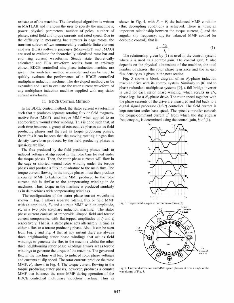
The configuration of the stator phase current waveforms shown in Fig. 3 allows separate rotating flux or field MMF with an amplitude, Ff, and a torque MMF with an amplitude, Ft, in a two pole six-phase induction machine. The stator phase current consists of trapezoidal-shaped field and torque current components, with flat-topped amplitudes of If and It respectively. That is, a stator phase acts alternately in time as either a flux or a torque producing phase. Also, it can be seen from Fig. 3 and Fig. 4 that at any instant there are always three neighbouring stator phase windings that act as field windings to generate the flux in the machine whilst the other three neighbouring stator phase windings always act as torque windings to generate the torque of the machine. The generated flux in the machine will lead to induced rotor phase voltages and currents at slip speed. The rotor currents produce the rotor MMF, Fr, shown in Fig. 4. The torque current flowing in the torque producing stator phases, however, produces a counter MMF that balances the rotor MMF during operation of the BDCE controlled multiphase induction machine. Thus as
shown in Fig. 4, with Ft = Fr the balanced MMF condition (flux decoupling condition) is achieved. There is, thus, an important relationship between the torque current, It, and the angular slip frequency, ωsl, for balanced MMF control (or decouple control), that is
sl
t
kI
ω= . (1)
The relationship given by (1) is used in the control system, where k is used as a control gain. The control gain, k, also depends on the physical dimensions of the machine, the total number of phases, the rotor phase resistance and the air-gap flux density as is given in the next section.
Fig. 5 shows a block diagram of an Np-phase induction machine drive with its control system. Similarly to [8] and to phase redundant multiphase systems [9], a full bridge inverter is used for each stator phase winding, which results in 2Np phase legs for a Np-phase drive. The rotor speed together with the phase currents of the drive are measured and fed back to a digital signal processor (DSP) controller. The field current is kept constant under base speed. The speed controller controls the torque-command current It
* from which the slip angular frequency ωsl is determined using the control gain, k, of (1).
fI tI
Fig. 3. Trapezoidal six-phase current waveforms [2].
Fig. 4. Current distribution and MMF space phasors at time t = t1/2 of the waveforms of Fig. 3.
947

Σ
k
+
unit
Σ
unit
X
Xx = 0, 1,…,(Np-1)
ΣNp -
phase Inverter
t
Low pass
speed filter
LEM Currentsensors
Np -PhaseInduction
Motor
Np
Np NpNp
NpIt
If
+
++
-+
ix*
ix
θωsl
ωr
Hysteresis Current Controller
DSP Control System
Resolver
r
ψf
T
e-jφ
(Phase shifter)
*
*
Fig. 5. BDCE control system of a Np-phase induction motor .
From this and from the known field-command current If*,
the Np reference phase currents of the drive are generated. In this case, a digitally implemented hysteresis current regulator, using a field programmable gate array (FPGA), is used for the current control. The switching signals are sent to the inverter via fibre optic cables. The advantage of this control method is that it does not require any transformations and model representations such as in vector control and DTC.
III. THEORETICAL EVALUATION OF THE ROTOR BAR AND END RING CURRENT WAVEFORMS
To simplify the evaluation of the current waveforms, the trapezoidal stator current waveform is broken down to its harmonic frequency components through Fourier transformations. Furthermore, the following assumptions are made; each harmonic component is a perfect sinusoid and each component acts independently of the others [that is, each stator current harmonic can be analysed individually (independently).], saturation is ignored, a uniform air-gap is considered, Np identical stator windings with axes of symmetry and n identical rotor windings with axes of symmetry are considered. Also, there are no eddy currents, friction-and-windage losses are ignored, and the rotor bars are assumed to be insulated. The current waveforms can be evaluated through the use of rotor voltage equations.
The cage rotor can be represented by Fig. 6 where R is resistance, L is inductance and the subscripts e and b denote end ring and rotor bar respectively. Thus, the rotor is viewed as n identical and equally spaced rotor loops [5-7]. Also, the nth loop consists of the nth and the (n + 1)th rotor bars together with the connecting end ring segments between them. Since there are n bars in the cage rotor, there are n + 1 independent rotor currents comprising of n loop currents and a circulating current in one of the rotor end rings.
With the cage rotor replaced with mutually coupled loops, the voltage equations for the rotor loops in vector-matrix form are
ddt
rr r r
ΛV = R I + , (2)
where, Vr is the rotor loop voltage vector, Rr is an (n + 1) by (n + 1) symmetric rotor loop resistance matrix, Ir is the loop currents vector and rΛ is the rotor loop flux linkages matrix. The rotor loop voltage vector for the cage rotor can also be written as
1 2 .........
0 0 ........ 0 0
,
t
r r rn e
t
v v v v
ddt
⎡ ⎤= ⎣ ⎦
⎡ ⎤= ⎣ ⎦
=
r
rr r
V
ΛR I +
(3)
where t represents a vector or matrix transpose. Therefore, the rotor loop flux linkages can be calculated from the loop voltage equations as
.
ddt
dt= ∫
rr r
r r r
Λ= -R I
Λ -R I
(4)
Fig. 6. Equivalent circuit of a squirrel cage rotor showing rotor loop currents.
948
Alternately, the rotor flux linkage is given by
,=r rs s rr r
tsr s rr r
Λ = L I + L I
L I + L I (5)
where Lrs is the mutual inductance matrix between rotor loop circuits and stator phases and Lsr is the mutual inductance matrix between stator phases and rotor loop circuits, Is is the stator current vector and Lrr is the (n +1) by (n + 1) symmetric rotor loop inductance matrix. In this analysis, it is assumed that Lrs = t
srL where tsrL is the transpose of the matrix Lsr.
From Fig. 6, the matrices Rr, Lsr and Lrr are given in the Appendix. The stator current vector is given by
[ ]1 2 ..... ts s smi i i=sI , (6)
and the rotor circuit current vector is expressed as
1 2.....t
r r rn rei i i i⎡ ⎤= ⎣ ⎦rI . (7)
In (7), ire is the end ring current. Here, the motor is assumed to have complete end rings (no broken segments) and hence, ire is equal to zero. The current vector can be obtained by making Ir the subject of equation (5), that is
1 1− − tr rr r rr sr sI = L Λ - L L I . (8)
As previously stated, the current Ir is an instantaneous current matrix resulting from the application of only one stator current frequency component in the machine. It is noted that these equations represent instantaneous values. Considering the rotor circuit currents in Fig. 6, the instantaneous current flowing in the nth bar is given by
( ) ( 1)( ) ( ) ( )bx n rn r ni t i t i t+= − . (9)
In (9), x is the xth stator current time harmonic order. Furthermore, it is noted that the current flowing in an end ring segment of Fig. 6 is equal to the loop circuit current defined for the particular segment, that is,
( ) ( ) ( )es n rni t i t= . (10)
IV. RESULTS
A simulation algorithm written in MATLAB is used to evaluate the rotor bar and end ring current waveform of a machine using the analysis acquired for an individual stator current component. The parameters of the machine are given in Table 1. The instantaneous contributions of individual stator harmonic currents to the rotor bar and end ring current waveforms, torque or rotor copper losses are simply added during simulation. The sum, then, represents the performance of the machine when fed with trapezoidal stator current waveforms. For example, the total instantaneous current induced in rotor bar 1 can be written as
1 11
( )b bxx
i i t∞
=
=∑ , (11)
where, x is the stator current time harmonic and ibx1(t) is calculated from (9). Considering frequency dependency, the rotor bar resistance and inductance are calculated through the method proposed by Babb and Williams [10, 11].
TABLE 1
PARAMETERS OF A 4-POLE 9-PHASE INDUCTION MACHINE
Rated Power, Pn 11kW
Air-gap length, g 0.5 mm
Stack length, l 127 mm (copper bars)
Rotor radius 84.5 mm
End ring segment resistance, Re 1.28e-6 Ω (75oC)
End ring segment inductance, Ler 29.2 nH
Number of field phases, mf 3
Number of torque phases, mt 6
Number of rotor bars, Mr 28
Number of stator slots, Ms 36
Number of series turns per stator phase, Ns 170
Torque current, It 5.5 A
Field current, If 5.83 A
Bar height 25 mm
Bar width 4.5mm
Operating speed 1472 r/min
Commercial FEA software packages, from Ansoft
(Maxwell2D) and from JMAG, are used to evaluate the analytically predicted the rotor bar and end ring current waveforms. The transient solvers in these packages are used because they allow for the use of non-sinusoidal current excitations and rotational motion.
Since the induction machine under consideration is symmetrical, only a quarter of a nine-phase four pole machine is modelled in Maxwell2D, whilst in JMAG, half of the machine is modelled since it is a cage rotor induction machine. In the models, Dirichlet boundary conditions are applied to the stator outer and rotor inner diameter. The vector potential is tangential and defined as zero at the stator outer and rotor inner diameter. Master / slave boundaries are defined on the other edges of the model. These boundaries force the magnetic field at each point on the master boundary to match the magnetic field at each corresponding point on the slave boundary. In Maxwell2D, the field on the slave boundary is defined to point in the exact opposite direction of the field on the master boundary and on JMAG, a periodic boundary is defined.
In the transient solvers, rotational motion is defined as occurring inside a selected band object. The band object is defined to cover the rotor of the machine in the models. Also, for the stator coils, stranded conductors are selected, whilst for the rotor bars solid conductors are used. The contribution of the stranded conductors to the current density is averaged over the slot area because such conductors lack eddy current behaviour in the transient solver. However, for solid conductors, skin effects are considered and they depend on the frequency of the system as well as on the location of nearby conductors.
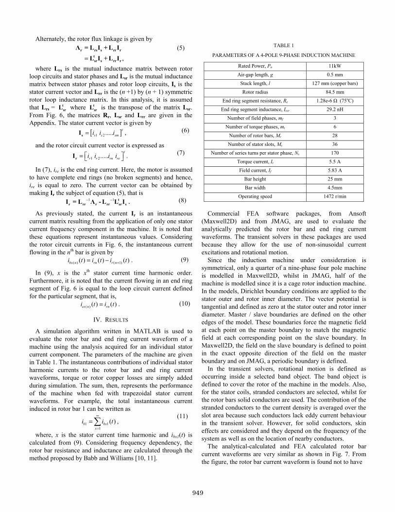
The analytical-calculated and FEA calculated rotor bar current waveforms are very similar as shown in Fig. 7. From the figure, the rotor bar current waveform is found not to have
949
-1000
-500
0
500
1000
0 1 2 3 4 5
Cur
rent
(A)
Time (s)
a)
-1000
-500
0
500
1000
0 1 2 3 4 5
Bar
cur
rent
(A)
Time (s)
b)
-1000
-500
0
500
1000
0 1 2 3 4 5
Bar
cur
rent
(A)
Time (s)
c)
-1000
-500
0
500
1000
0 1 2 3 4 5
Bar
cur
rent
(A)
Time (s)
d) Fig. 7. Comparison of analytically calculated and FEA calculated rotor bar current waveforms at operating speed of 1466 r/min, If = 5.83 A and It = 5.5 A; a) assumed waveform according to Section II, b) evaluated waveform from (9), c) Maxwell2D waveform and d) JMAG waveform.
-2000
-1000
0
1000
2000
0 1 2 3 4 5
End
ring
curr
ent (
A)
Time (s)
a)
-2000
-1000
0
1000
2000
0 1 2 3 4 5
End
ring
curr
ent (
A)
Time (s)
b) Fig. 8. Comparison of analytically calculated [a) using (10)] and FEA calculated [b) using JMAG] rotor end ring current waveforms at 1466 r/min, If = 5.83 A and It = 5.5 A.
a quasi-square wave shape as assumed in the theory. The analytically calculated and JMAG evaluated rotor end ring current waveforms are shown in Fig. 8. There is an observable and good similarity between the waveforms. The FEA results of Fig. 7 and Fig. 8 validates the analytical method of finding the rotor bar and end ring current waveforms.
V. CONCLUSION
In this paper, a simple quicker method of predicting and evaluating the rotor bar and end ring current waveforms is presented in the paper. Although the rotor bar current waveform is found to differ from the assumed square-like waveform, it is argued that this difference may not simply be explained by transformer action, but rather by the same effect that is happening in dc commutator machines (armature reaction). Therefore, the analytical method of calculating the rotor bar and end ring current waveforms can be used in the preliminary performance study of BDCE controlled multiphase induction machines. Once the rotor current waveform is evaluated, the bar copper losses can be predicted as well as the torque in the machine.
APPENDIX
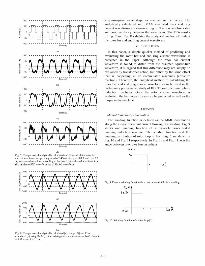
Mutual Inductance Calculation The winding function is defined as the MMF distribution
along the air-gap for a unit current flowing in a winding. Fig. 9 shows one winding function of a two-pole concentrated winding induction machine. The winding function and the winding distribution of rotor loop r1 from Fig. 6 are shown in Fig. 10 and Fig. 11 respectively. In Fig. 10 and Fig. 11, α is the angle between two rotor bars in radians.
Fig. 9. Phase a winding function for a concentrated full pitch winding.
Fig. 10. Winding function of a rotor loop [5].
950

Fig. 11. Winding distribution of a rotor loop [5].
The winding function is defined as the MMF distribution
along the air-gap for a unit current flowing in a winding. The winding function theory approach presented in [5-7] states that the mutual inductance between any two windings i and j in any electrical machine can be calculated as
( ) ( )20
0
gij i r j r r
r lL n N d
gπμ
θ θ θ= ∫ , (12)
where rg is the average radius of the air-gap, l is the stack length, g is the air-gap length, θr is the spatial mechanical angle of the rotor with reference to a stationary point on the stator, ni(.) is the ith winding distribution and Nj(.) is the jth winding function. Equation (12) is used to calculate the mutual inductances of (13)
1 1 1 2 1 1
2 1 2 2 2 2
1 2
. .
. .. . . . . .
. .
s r s r s rn s re
s r s r s rn s re
smr smr smrn smre
L L L LL L L L
L L L L
⎡ ⎤⎢ ⎥⎢ ⎥=⎢ ⎥⎢ ⎥⎣ ⎦
srL (13)
( )( )
( )( )
b e b b e
b b e b e
b e b e
b b b e e
e e e e e e
2 R +R -R 0 .......... 0 -R -R-R 2 R +R -R .......... 0 0 -R
. . . .......... . . .= .. . . .......... . . .
0 0 0 .......... 2 R +R -R -R-R 0 0 .......... -R 2 R +R -R-R -R -R .......... -R -R nR
⎡ ⎤⎢ ⎥⎢ ⎥⎢ ⎥⎢ ⎥⎢ ⎥⎢ ⎥⎢ ⎥⎢ ⎥⎢ ⎥⎢ ⎥⎢ ⎥⎣ ⎦
rR
(14)
( )( )
( )
1 2 1 3 1 ( 1) 1
2 1 2 3 2 ( 1) 2
( 1) 1 ( 1) 2 ( 1) 3 ( 1)
2 ..........2 ..........
. . . .......... . . .
. . . .......... . . ........... 2
mr b e r r b r r r r n r rn b e
r r b mr b e r r b r r n r rn e
r n r r n r r n r mr b e r n rn
L L L L L L L L L LL L L L L L L L L L
L L L L L L L L
−
−
− − − −
+ + − − −− + + − −
=+ + −
rrL
( )1 2 3 ( 1).......... 2..........
b e
rnr b rnr rnr rnr n b mr b e e
e e e e e e
LL L L L L L L L L L
L L L L L nL−
⎡⎢⎢⎢⎢⎢⎢ −⎢
− − + + −⎢⎢ − − − − −⎣
(15)
REFERENCES [1] E. Levi, R. Bojoi, F. Profumo, H. A. Toliyat, and S. Williamson,
"Multiphase Induction Motor Drives - A Technology Status Review," IEE Proceedings - Electric Power Applications, vol. 1, pp. 489-516, July 2007.
[2] Y. Ai, M. J. Kamper, and A. D. L. Roux, "Novel Direct Flux and Direct Torque Control of Six-Phase Induction Machine with Nearly Square Air Gap Flux Density," IEEE Transactions on Industry Applications, vol. 43, pp. 1534-1543, December 2007.
[3] N. Gule and M. J. Kamper, "Multi-phase Cage Rotor Induction Machine with Direct Implementation of Brush DC Operation," in International Electric Machines and Drives Conference (IEMDC2011) Niagara Falls, Canada, 2011.
[4] N. Gule and M. J. Kamper, "Optimal Ratio of Field to Torque Phases in Multi-Phase Induction Machines Using Special Phase Current Waveforms," in Proceedings of International Conference on Electrical Machines (ICEM2008), 2008.
[5] H. A. Toliyat, T. A. Lipo, and J. C. White, "Analysis of a Concentrated Winding Induction Machine for Adjustable Speed Drive Applications: Part 1 (Motor Analysis)," IEEE Transactions on Energy Conversion, vol. 6, pp. 679-683, 1991.
[6] H. A. Toliyat, T. A. Lipo, and J. C. White, "Analysis of a Concentrated Winding Induction Machine for Adjustable Speed Drive Applications: Part 2 (Motor Design and Performance)," IEEE Transactions on Energy Conversion, vol. 9, pp. 692-700, 1991.
[7] H. A. Toliyat and T. A. Lipo, "Transient Analysis of Cage Induction Machines Under Stator, Rotor Bar and End Ring Faults," IEEE Transactions on Energy Conversion, vol. 10, pp. 241-247, 1995.
[8] L. Weichao, H. An, G. Shiguang, and S. Chi, "Rapid Control Prototyping of Fifteen-Phase Induction Motor Drives Based on dSPACE," in International Conference on Electrical Machines and Systems, ICEMS 2008, 2008.
[9] G. K. Singh, "Multi-Phase Induction Machine Drive Research - A survey," Elsevier Electric Power Systems Research, pp. 139-147, 2002.
[10] D. S. Babb and J. E. Williams, "Circuit Analysis Method for Determination of A-C Impedances of Machine Conductors," AIEE Transactions (Power Apparatus and Systems), vol. 70, pp. 661-666, 1951.
[11] D. S. Babb and J. E. Williams, "Network Analysis of A-C Machine Conductors," AIEE Transactions (Power Apparatus and Systems), vol. 70, pp. 2001-2005, 1951.
951

952
Powered by TCPDF (www.tcpdf.org)