evaluation of the performance of full-scale rc beams
TRANSCRIPT
Page 1 of 6
The 7th International Conference on FRP Composites in Civil Engineering
International Institute for FRP in Construction
EVALUATION OF THE PERFORMANCE OF FULL-SCALE RC BEAMS PRESTRESSED WITH NSM-CFRP LAMINATES
Inês COSTA PhD student, ISISE - University of Minho, Portugal [email protected]
Mohammadali REZAZADEH PhD student, ISISE - University of Minho, Portugal [email protected]
Joaquim BARROS Full Professor, ISISE - University of Minho, Portugal [email protected]
ABSTRACT: Carbon Fibre Reinforced Polymers (CFRP) applied according to the Near Surface Mounted (NSM) technique are known as capable of increasing the ultimate flexural resistance of Reinforced Concrete (RC) elements, but for Serviceability Limit States (SLS) the load increment it provides is, in general, relatively limited. Recently, researchers are giving attention towards the possibility of applying prestressed NSM-CFRPs to increase significantly the load carrying capacity of RC elements at SLS. As it is common knowledge, introducing prestress in a RC element produces an initial stress distribution, whose primary effect is, in the case of RC beams, the development of an initial deflection, typically in the opposite direction of loading. This initial stress field is the key factor that triggers most of the benefits of this technology, such as the delay in crack initiation and in steel yielding initiation. In this paper, the results of an experimental program consisting of a series of full-scale RC beams flexurally strengthened with NSM prestressed CFRP laminates up to four different levels (20%, 30%, 40% and 50%) will be presented. The experimental program is described and the main results are presented and discussed.
1. Introduction
The Near Surface Mounted (NSM) strengthening technique, which consists of bonding the FRP material (a laminate or a rod) into a groove open on the concrete cover, has already proven to be capable of increasing the load carrying capacity of RC elements strengthened either in bending or shear (Barros & Fortes 2005, Barros et al. 2007). However, the installation of passive FRP systems provides only a modest increase of the load carrying capacity at serviceability limit states. In an attempt of overcoming this limitation, the use prestressed FRP has been suggested by some authors (Wight et al. 2001, Nordin & Täljsten 2006, Gaafar & El-Hacha 2008). Apart from the benefits in terms of load carrying capacity at SLS, strengthening with prestressed FRPs may be able of closing or reducing the width of existing cracks, as well as delaying the appearance of new fissures, resulting in benefits in terms of structural integrity and concrete durability.
This paper reports the benefits and the weaknesses resulting from the application of NSM-CFRP laminates observed on an experimental program composed of six full-scale RC beams strengthened with CFRP laminates.
2. Experimental program
The experimental program reported in this paper is composed of six 150×300×4000 mm3 RC beams reinforced with two longitudinal bars of 10 mm diameter both in the tension and compression zones. To prevent shear failure, 6 mm steel stirrups with 100 mm spacing were also applied. One of the beams did not receive any type of CFRP strengthening and served as a reference beam, while another one was chosen to be strengthened with a 1.4×20 mm2 CFRP laminate without any prestress. The four remaining beams were strengthened with the same type of NSM-CFRP laminate (one laminate per beam) but prestressed up to 20%, 30%, 40% and 50% of their ultimate nominal strain, which is 13.333‰. In reality, the effective strain applied in each of the laminates was about 2.690‰, 4.000‰, 5.354‰ and 6.621‰. All
Page 2 of 6
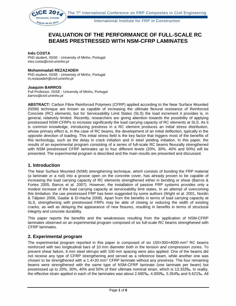
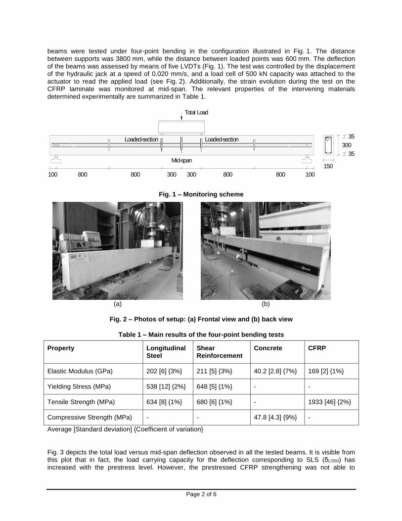
beams were tested under four-point bending in the configuration illustrated in Fig. 1. The distance between supports was 3800 mm, while the distance between loaded points was 600 mm. The deflection of the beams was assessed by means of five LVDTs (Fig. 1). The test was controlled by the displacement of the hydraulic jack at a speed of 0.020 mm/s, and a load cell of 500 kN capacity was attached to the actuator to read the applied load (see Fig. 2). Additionally, the strain evolution during the test on the CFRP laminate was monitored at mid-span. The relevant properties of the intervening materials determined experimentally are summarized in Table 1.
Mid-span
Loaded-sectionLoaded-section
100 800 800 300 300 800 800 100
Total Load
150
300
35
35
Fig. 1 – Monitoring scheme
(a)
(b)
Fig. 2 – Photos of setup: (a) Frontal view and (b) back view
Table 1 – Main results of the four-point bending tests
Property Longitudinal Steel
Shear Reinforcement
Concrete CFRP
Elastic Modulus (GPa) 202 [6] {3%} 211 [5] {3%} 40.2 [2.8] {7%} 169 [2] {1%}
Yielding Stress (MPa) 538 [12] {2%} 648 [5] {1%} - -
Tensile Strength (MPa) 634 [8] {1%} 680 [6] {1%} - 1933 [46] {2%}
Compressive Strength (MPa) - - 47.8 [4.3] {9%} -
Average [Standard deviation] {Coefficient of variation}
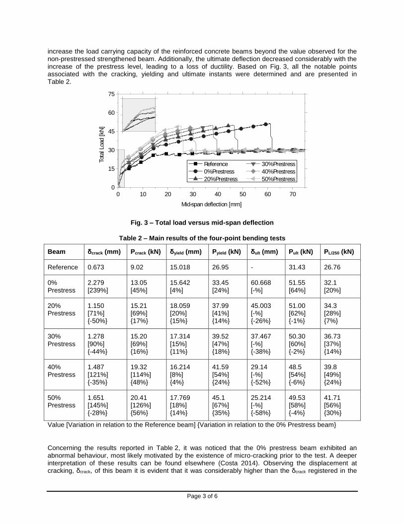
Fig. 3 depicts the total load versus mid-span deflection observed in all the tested beams. It is visible from this plot that in fact, the load carrying capacity for the deflection corresponding to SLS (δL/250) has increased with the prestress level. However, the prestressed CFRP strengthening was not able to
Page 3 of 6
increase the load carrying capacity of the reinforced concrete beams beyond the value observed for the non-prestressed strengthened beam. Additionally, the ultimate deflection decreased considerably with the increase of the prestress level, leading to a loss of ductility. Based on Fig. 3, all the notable points associated with the cracking, yielding and ultimate instants were determined and are presented in Table 2.
0 10 20 30 40 50 60 700
15
30
45
60
75
Tot
al L
oad [
kN]
Mid-span deflection [mm]
Reference 30% Prestress
0% Prestress 40% Prestress
20% Prestress 50% Prestress
Fig. 3 – Total load versus mid-span deflection
Table 2 – Main results of the four-point bending tests
Beam δcrack (mm) Pcrack (kN) δyield (mm) Pyield (kN) δult (mm) Pult (kN) PL/250 (kN)
Reference 0.673 9.02 15.018 26.95 - 31.43 26.76
0% Prestress
2.279 [239%]
13.05 [45%]
15.642 [4%]
33.45 [24%]
60.668 [-%]
51.55 [64%]
32.1 [20%]
20% Prestress
1.150 [71%] {-50%}
15.21 [69%] {17%}
18.059 [20%] {15%}
37.99 [41%] {14%}
45.003 [-%] {-26%}
51.00 [62%] {-1%}
34.3 [28%] {7%}
30% Prestress
1.278 [90%] {-44%}
15.20 [69%] {16%}
17.314 [15%] {11%}
39.52 [47%] {18%}
37.467 [-%] {-38%}
50.30 [60%] {-2%}
36.73 [37%] {14%}
40% Prestress
1.487 [121%] {-35%}
19.32 [114%] {48%}
16.214 [8%] {4%}
41.59 [54%] {24%}
29.14 [-%] {-52%}
48.5 [54%] {-6%}
39.8 [49%] {24%}
50% Prestress
1.651 [145%] {-28%}
20.41 [126%] {56%}
17.769 [18%] {14%}
45.1 [67%] {35%}
25.214 [-%] {-58%}
49.53 [58%] {-4%}
41.71 [56%] {30%}
Value [Variation in relation to the Reference beam] {Variation in relation to the 0% Prestress beam}
Concerning the results reported in Table 2, it was noticed that the 0% prestress beam exhibited an abnormal behaviour, most likely motivated by the existence of micro-cracking prior to the test. A deeper interpretation of these results can be found elsewhere (Costa 2014). Observing the displacement at cracking, δcrack, of this beam it is evident that it was considerably higher than the δcrack registered in the
Page 4 of 6
other tested beams (2.279 mm, opposed to deflections ranging between 0.673 mm and 1.651 mm). However, in terms of load at cracking, Pcrack, considerable increases were observed due to the application of the CFRP strengthening. It is worth noting that although the beams reinforced with 20% and 30% conducted to roughly the same increment of the cracking load, when compared to the reference beam (69%), the application of 50% more than doubled the initial elastic load-carrying capacity of the reference beam at this stage (126%).
In terms of yielding load, Pyield, the prestressed strengthening demonstrated the capacity of increasing the load carrying capacity (41%~47%~54%~67%) at this level, while in terms of yielding deflection, δyield, a decreased was observed with the increase of prestress level (15%~11%~4%~14%), probably due to some variation of the yielding strain.
Regarding the ultimate load carrying capacity of the beams, Pult, the increment provided by the prestressed CFRP laminate was, as already mentioned, approximately the same in all the RC beams (both non-prestressed and prestressed). In addition, a significant decrease of deflection at failure, δult, was detected, fairly proportional to the applied prestress level. Taking as example the 40% prestress beam, it was determined that this beam experienced a decrease of 52% in ultimate deflection, while the 20% prestress beam endured exactly half of that amount, 26%.
Finally, in terms of load carrying capacity at δL/250, PL/250, it was increased with the level of prestress. In
fact, while the control beam has presented δyield δL/250 = 15.2 mm, the application of prestress allowed the increase of the service capacity reasonably, enlarging the displacement between δyield and δL/250.
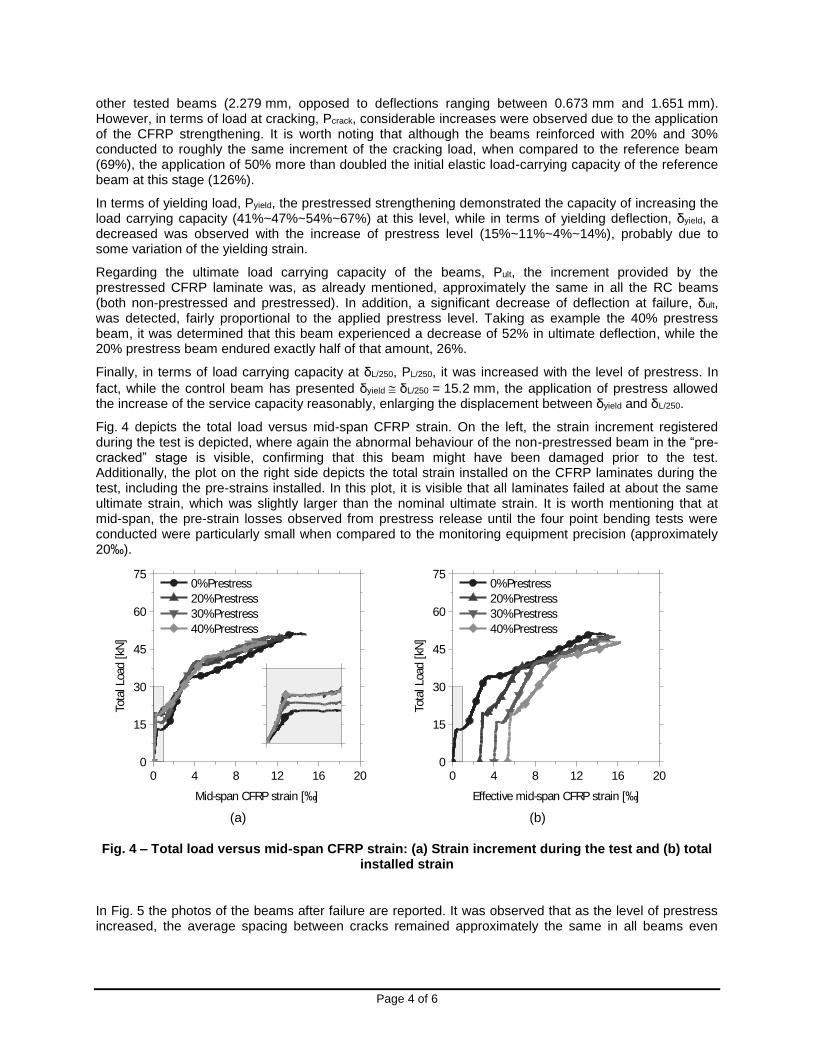
Fig. 4 depicts the total load versus mid-span CFRP strain. On the left, the strain increment registered during the test is depicted, where again the abnormal behaviour of the non-prestressed beam in the “pre-cracked” stage is visible, confirming that this beam might have been damaged prior to the test. Additionally, the plot on the right side depicts the total strain installed on the CFRP laminates during the test, including the pre-strains installed. In this plot, it is visible that all laminates failed at about the same ultimate strain, which was slightly larger than the nominal ultimate strain. It is worth mentioning that at mid-span, the pre-strain losses observed from prestress release until the four point bending tests were conducted were particularly small when compared to the monitoring equipment precision (approximately 20‰).
0 4 8 12 16 200
15
30
45
60
75
Tot
al L
oad [
kN]
Mid-span CFRP strain [‰]
0% Prestress
20% Prestress
30% Prestress
40% Prestress
(a)
0 4 8 12 16 200
15
30
45
60
75
Tot
al L
oad [
kN]
Effective mid-span CFRP strain [‰]
0% Prestress
20% Prestress
30% Prestress
40% Prestress
(b)
Fig. 4 – Total load versus mid-span CFRP strain: (a) Strain increment during the test and (b) total installed strain
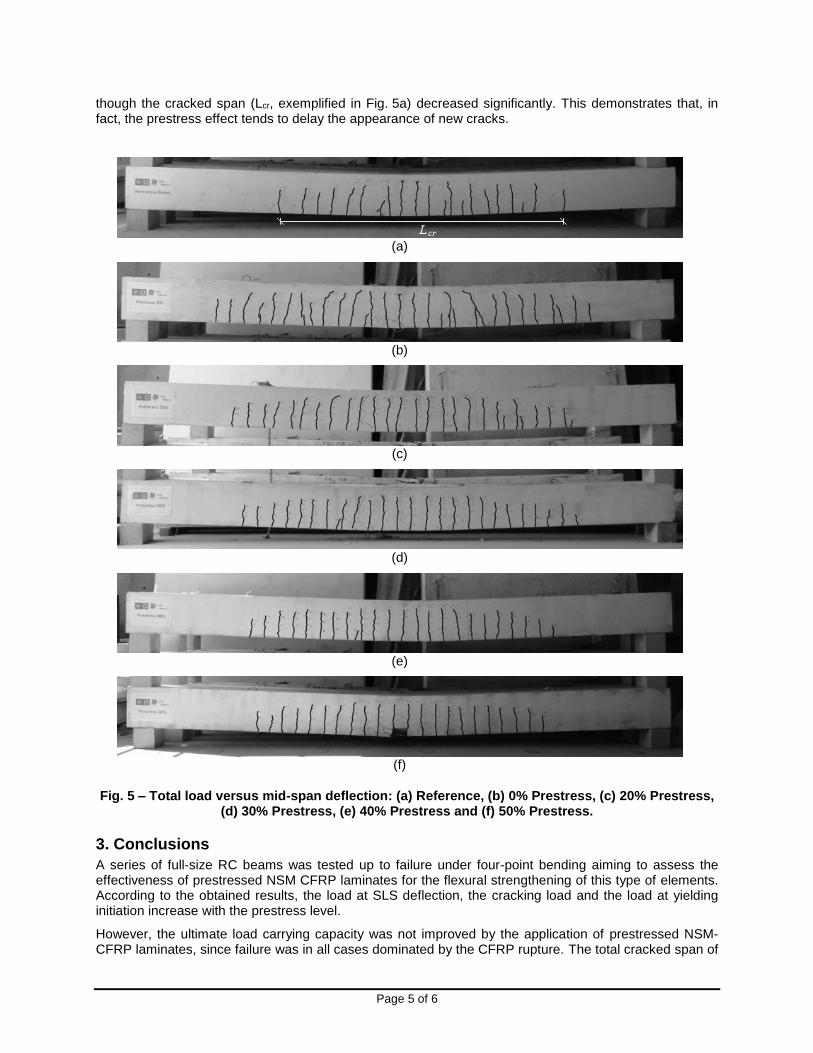
In Fig. 5 the photos of the beams after failure are reported. It was observed that as the level of prestress increased, the average spacing between cracks remained approximately the same in all beams even
Page 5 of 6
though the cracked span (Lcr, exemplified in Fig. 5a) decreased significantly. This demonstrates that, in fact, the prestress effect tends to delay the appearance of new cracks.
(a)
(b)
(c)
(d)
(e)
(f)
Fig. 5 – Total load versus mid-span deflection: (a) Reference, (b) 0% Prestress, (c) 20% Prestress, (d) 30% Prestress, (e) 40% Prestress and (f) 50% Prestress.
3. Conclusions
A series of full-size RC beams was tested up to failure under four-point bending aiming to assess the effectiveness of prestressed NSM CFRP laminates for the flexural strengthening of this type of elements. According to the obtained results, the load at SLS deflection, the cracking load and the load at yielding initiation increase with the prestress level.
However, the ultimate load carrying capacity was not improved by the application of prestressed NSM-CFRP laminates, since failure was in all cases dominated by the CFRP rupture. The total cracked span of

Page 6 of 6
the beams was significantly reduced by the presence of an initial prestress. Regarding the average crack spacing, it was in all beams approximately the same and about the same as the shear reinforcement spacing.
In general, the deflections measured in the beams decreased with the increase of the applied prestress level, which means that the ductility of the strengthened beams reduces with the increase of the prestress level, as schematized in Fig. 6.
P
mid-span
ReferenceBeam
1 2 3
Pultimate
2x% x% 0%
(1 - c)·1
3 (1 - 2c)·
1
2
Fig. 6 – Total load versus mid-span deflection
4. Acknowledgements
The study reported in this paper was supported by FCT, SFRH/BD/61756/2009, and is part of the project PreLami - Performance of reinforced concrete structures strengthened in flexural with an innovative system using prestressed NSM CFRP laminates, with the reference PTDC/ECM/114945/2009. The authors would also like to acknowledge the support provided by Pregaia for producing the concrete beams and S&P for supplying the CFRP and adhesives for the experimental program.
5. References
Barros, J. A. O. and Fortes, A. S., “Flexural strengthening of concrete beams with CFRP laminates
bonded into slits”, Cement & Concrete Composites, Vol. 27, No. 4, 2005, pp. 471-480.
Barros, J. A. O.; Dias, S. J. E. and Lima, J. L. T., “Efficacy of CFRP-based techniques for the flexural and
shear strengthening of concrete beams”, Cement & Concrete Composites, Vol. 29, No. 3, 2007,
pp. 203-217.
Costa, I. G., “Prestressed Carbon Fibre laminates applied according to Near Surface Mounted technique
to increase the flexural resistance of Reinforced Concrete beams”, PhD Thesis, defence scheduled
to June 2, 2014.
Gaafar, M. A. and El-Hacha, R., “Strengthening reinforced concrete beams with prestressed FRP near
surface mounted technique”, Proceedings of the Fourth International Conference on FRP
Composites in Civil Engineering, 22-24 July 2008, 6 pp.
Nordin, H. and Täljsten, B.,. “Concrete Beams Strengthened with Prestressed Near Surface Mounted
CFRP”, Journal of Composites for Construction, Vol. 10, No. 1, 2006, pp. 60-68.
Wight, R. G.; Green, M. F. and Erki, M-A., “Prestressed FRP Sheets for Poststrengthening Reinforced
Concrete Beams.” Journal of Composites for Construction, Vol. 5, No. 4, 2001, pp. 214-220.