evaluation of the impact of a synthetic paraffinic ... · additive package and api 1581 3rd edition...
TRANSCRIPT

UNCLASSIFIED
Approved for public release; distribution is unlimited
UNCLASSIFIED
E VA L UA T I O N O F T H E I M PA C T O F A S Y N T H E T I C PA R A F F I N I C K E RO S E N E A N D
J P - 8 B L E N D O N F I LT E R S A N D F I LT E R / C OA L E S C E R P E R F O R M A N C E
NAVAIRSYSCOM REPORT 441/09-003
11 August 2009
Prepared by: Michael Domen
Chemical Engineer AIR-4.4.5.1
Telephone 301-757-3410 Approved by: Richard Kamin
Fuels Team Lead AIR-4.4.5
Telephone 301-757-3408
Released by: DOUGLAS F. MEARNS Fuels & Lubricants Systems Engr.
AIR-4.4.1 Telephone 301-757-3421

UNCLASSIFIED NAVAIRSYSCOM REPORT 441/09-003 11 August 2009 Page ii
UNCLASSIFIED
Report prepared and released by:
Naval Air Systems Command, AIR-4.4.1 Naval Fuels and Lubricants Cross Functional Team
22229 Elmer Road Patuxent River MD 20670-1534

UNCLASSIFIED NAVAIRSYSCOM REPORT 441/09-003
11 August 2009 Page iii
UNCLASSIFIED
TABLE OF CONTENTS
Page
LIST OF TABLES................................................................................................................................v
LIST OF FIGURES.............................................................................................................................vi
EXECUTIVE SUMMARY ............................................................................................................... vii
LIST OF ACRONYMS/ABBREVIATIONS................................................................................... viii
1.0 BACKGROUND...........................................................................................................................1
2.0 OBJECTIVE..................................................................................................................................1
3.0 APPROACH..................................................................................................................................1
3.1 Impact on Filter/Coalescer Performance .....................................................................................1
3.2 Impact on Material Compatibility................................................................................................1
3.3 Fuels and Additives .....................................................................................................................3
3.4 Protocols and Limits ....................................................................................................................4
3.4.1 Single Element Testing...........................................................................................................4
3.4.2 Material Compatibility Testing ..............................................................................................4
4.0 DISCUSSION................................................................................................................................5
4.1 Single Element Testing ...............................................................................................................5
4.1.1 Test 1.......................................................................................................................................5
4.1.2 Test 2.......................................................................................................................................6
4.1.3 Test 3.......................................................................................................................................6
4.1.4 Test 4.......................................................................................................................................7
4.1.5 Test 5.......................................................................................................................................8
4.1.6 Test 6.......................................................................................................................................8
4.1.7 Test 7.......................................................................................................................................9
4.1.8 Test 8.......................................................................................................................................9
4.2 Material Compatibility Testing..................................................................................................10
4.2.1 Test 1.....................................................................................................................................11
4.2.2 Test 2.....................................................................................................................................11
5.0 CONCLUSIONS .........................................................................................................................11
5.1 Single Element Testing..............................................................................................................11
5.2 Material Compatibility Testing..................................................................................................12

UNCLASSIFIED NAVAIRSYSCOM REPORT 441/09-003 11 August 2009 Page iv
UNCLASSIFIED
TABLE OF CONTENTS (cont.)
6.0 RECOMMENDATIONS.............................................................................................................12
7.0 REFERENCES ............................................................................................................................13
Appendix A: Filter Coalescer Performance Test Results................................................................ A-1
Appendix B: Material Compatibility Test Results ...........................................................................B-1
Appendix C: JFTOT Results from AFPET Laboratory....................................................................C-1
Appendix D: Results from Inductively Coupled Plasma Analysis.................................................. D-1

UNCLASSIFIED NAVAIRSYSCOM REPORT 441/09-003
11 August 2009 Page v
UNCLASSIFIED
LIST OF TABLES
Table Title Page
1 Single Element Testing Details..................................................................................................2
2 Material Compatibility Testing Details .....................................................................................2
3 Fuel Specification Test Results..................................................................................................3
4 Fuel Additives............................................................................................................................4
5 Single Element Test Protocol ....................................................................................................4
6 API 1581/MIL-PRF-32148 Pass/Fail Limits.............................................................................4
7 Material Compatibility Pass/Fail Requirements ........................................................................5
A-1 Single Element Test Data ....................................................................................Appendix A
B-1 3rd Ed Style Filter/Coalescer Compatibility Results ............................................ Appendix B
B-2 Category M Filter/Coalescer Compatibility Results............................................ Appendix B
B-3 Category M100 Filter/Coalescer Compatibility Results...................................... Appendix B
B-4 Cateogry M Separator Compatibility Results...................................................... Appendix B
B-5 Category C Filter/Coalescer Compatibility Results............................................. Appendix B
D-1 Results from ICP Metals Analysis on Material Compatibility Samples .............Appendix D

UNCLASSIFIED NAVAIRSYSCOM REPORT 441/09-003 11 August 2009 Page vi
UNCLASSIFIED
LIST OF FIGURES
Figure Title Page
1 20 gpm Vertical Canister Filter Separator ...........................................................................6
2 35 gpm Vertical Side by Side Filter Separator ....................................................................8
3 45.5 gpm Vertical Side by Side Filter Separator .................................................................9
4 4 inch element housings.....................................................................................................10
5 6 inch element housing ......................................................................................................10

UNCLASSIFIED NAVAIRSYSCOM REPORT 441/09-003
11 August 2009 Page vii
UNCLASSIFIED
EXECUTIVE SUMMARY
Synthetic Paraffinic Kerosene (SPK) is a liquid hydrocarbon fuel which can be produced by several different methods, one of which being the Fischer Tropsch (FT) process. First invented during the 1920’s, the FT process involves a chemical reaction which converts a hydrogen and carbon monoxide mixture into a liquid hydrocarbon fuel, typically from sources like coal or natural gas. Since 70 percent of the petroleum currently used in the U.S. is imported, certification of SPK is being pursued because of the benefits to energy security over traditional petroleum derived fuel. SPK can be made from domestic feed stocks which will reduce the U.S. dependence on foreign energy. The goal is to certify up to 50 percent synthetic aviation fuel in petroleum aviation fuel for use in military applications. This program evaluated the effects of a 50/50 blend of SPK and petroleum aviation fuel with and without the standard JP-8 additive package on filter/coalescer performance. The filter/coalescer elements tested were representative of those currently used in military and commercial filtration systems. The program included performance and compatibility testing. Results of the testing were: A neat 50/50 blend of SPK and petroleum aviation fuel did not adversely affect performance of API
1581 5th edition Category C or M100 style elements or MIL-PRF-32148 elements. A 50/50 blend of SPK and petroleum aviation fuel (with and without the standard JP-8 additive package)
performed identically to the 100% petroleum fuel when tested with API 1581 3rd edition style elements. Both the SPK/petroleum blend and the straight petroleum based fuel failed performance testing due to exceeding the differential pressure requirement during the solids injection.
A 50/50 blend of SPK and petroleum aviation fuel with the JP-8+100 additive package failed API 1581
5th edition Category M100 performance testing due to exceeding the differential pressure requirement during the solids injection. Test results indicate the 50/50 blend was not the cause for failure because the identical test with the neat 50/50 blend passed the API requirements.
Compatibility testing of a 50/50 blend of SPK and petroleum aviation fuel containing the standard JP-8
additive package and API 1581 3rd edition and 5th edition Category C, M, and M100 elements showed no impact to fuel properties or element integrity.
Compatibility testing of a neat 50/50 blend of SPK and petroleum aviation fuel and API 1581 5th edition
Category M100 and 3rd edition elements showed no impact on fuel properties or element integrity. Compatibility testing of a neat 50/50 blend of SPK and petroleum aviation fuel and API 1581 5th edition
Category M and C elements adversely impacted fuel thermal stability, however there was no impact to element integrity.

UNCLASSIFIED NAVAIRSYSCOM REPORT 441/09-003 11 August 2009 Page viii
UNCLASSIFIED
LIST OF ACRONYMS/ABBREVIATIONS
DoD...................................................................................... Department of Defense FSII ................................................................................Fuel System Icing Inhibitor FT.....................................................................................................Fischer Tropsch GC/MS.................................................... Gas Chromatography/Mass Spectroscopy ICP ............................................................................... Inductively Coupled Plasma JFTOT.................................................................Jet Fuel Thermal Oxidation Tester SET ........................................................................................... Single Element Test SPK ............................................................................Synthetic Paraffinic Kerosene WSIM..................................................................Water Separation Index, Modified

UNCLASSIFIED NAVAIRSYSCOM REPORT 441/09-003
11 August 2009 Page 1
UNCLASSIFIED
Evaluation of the Impact of a Synthetic Paraffinic Kerosene and JP-8 Blend on Filters and
Filter/Coalescer Performance
1.0 BACKGROUND Synthetic Paraffinic Kerosene (SPK) is a liquid hydrocarbon fuel which can be produced by several different methods, one of which being the Fischer Tropsch (FT) process. First invented during the 1920’s, the FT process involves a chemical reaction which converts a hydrogen and carbon monoxide mixture into a liquid hydrocarbon fuel, typically from sources like coal or natural gas. The goal is to certify up to 50 percent synthetic aviation fuel in petroleum aviation fuel for use in military applications. Since 70 percent of the petroleum currently used in the U.S. is imported, certification of SPK is being pursued because of the benefits to energy security over traditional petroleum derived fuel. SPK can be made from domestic feed stocks which will reduce the U.S. dependence on foreign energy. 2.0 OBJECTIVE This program evaluated the effects of a 50/50 blend of SPK and petroleum aviation fuel on military and commercial filter/coalescer performance in two phases. The first phase evaluated the effects on filter/coalescer performance of the SPK/petroleum blend with and without the required additives included in the JP-8 specification (MIL-DTL-83133). The second phase of the program evaluated the material compatibility between the SPK blend and the filter/coalescers and separators with and without the required additive package. 3.0 APPROACH 3.1 Impact on Filter/Coalescer Performance The first part of the test plan consisted of twelve single element tests (SET). The tests utilized filter elements that were manufactured in accordance with API 1581 3rd edition, 5th edition, and MIL-PRF-32148 for Navy shipboard filter elements. A list of the details of each test is shown in Table 1. 3.2 Impact on Material Compatibility The second part of the test plan consisted of testing the material compatibility between the SPK/petroleum blend fuel and the filter/coalescers and separators used in the first part of the test plan. The plan consisted of a modified version of API 1581 Section 4.6.2. A list of the details of the testing is shown in Table 2. The Category M separator, which is the Navy style element, was the only separator tested for this compatibility testing because the materials used presented the worst case scenario.

UNCLASSIFIED NAVAIRSYSCOM REPORT 441/09-003 11 August 2009 Page 2
UNCLASSIFIED
Table 1: Single Element Testing Details
Test No. Fuel
Element Type
Filter Element
Separator Type
Test Edition
Flow Rate
(gpm) Additives Primary
User
1A Pet. 3rd Ed. Style I-42087
Basket Type
API 1581 3rd Ed 20
Stadis 450, Hitec 580 Army
1B Pet. 3rd Ed. Style I-42087
Basket Type
API 1581 3rd Ed 20
Stadis 450, Hitec 580 Army
2A SPK/Pet.
3rd Ed. Style I-42087
Basket Type
API 1581 3rd Ed 20 N/A Army
2B SPK/Pet.
3rd Ed. Style I-42087
Basket Type
API 1581 3rd Ed 20 N/A Army
3 SPK/Pet.
3rd Ed. Style I-42087
Basket Type
API 1581 3rd Ed 20
Stadis 450, Hitec 580 Army
4A SPK/Pet.
3rd Ed. Style I-42087
Basket Type
API 1581 3rd Ed 20
Stadis 450, DCI-4A, DiEGME Army
4B SPK/Pet.
3rd Ed. Style I-42087
Basket Type
API 1581 3rd Ed 20
Stadis 450, DCI-4A, DiEGME Army
5 SPK/Pet.
Category M I-420MMF SS424Z
MIL-PRF-32148 35 N/A Navy
6 SPK/Pet.
Category M100 I-420A4
Basket Type
API 1581 5th Ed 20 N/A Air Force
7 SPK/Pet.
Category C TC-CO131
TC-S0113
API 1581 5th Ed 45.5 N/A Industry
8A SPK/Pet.
Category M100 I-420A4
Basket Type
API 1581 5th Ed 20
Stadis 450, DCI-4A, DiEGME, Spec-Aid 8Q462 Air Force
8B SPK/Pet.
Category M100 I-420A4
Basket Type
API 1581 5th Ed 20
Stadis 450, DCI-4A, DiEGME, Spec-Aid 8Q462 Air Force
Table 2: Material Compatibility Testing Details
Test No. Element Product No. Element Type Additives 1-1 F/C I-42087 3rd Ed. Style N/A 1-2 F/C I-420MMF 5th Ed. Category M N/A 1-3 F/C I-420A4 5th Ed. Category M100 N/A 1-4 Sep. SS424Z 5th Ed. Category M N/A 1-5 F/C TC-CO131 5th Ed. Category C N/A
2-1 F/C I-42087 3rd Ed. Style Stadis 450, DCI-4A, DiEGME
2-2 F/C I-420MMF 5th Ed. Category M Stadis 450, DCI-4A, DiEGME
2-3 F/C I-420A4 5th Ed. Category M100 Stadis 450, DCI-4A, DiEGME, Spec-Aid 8Q462
2-4 Sep. SS424Z 5th Ed. Category M Stadis 450, DCI-4A, DiEGME
2-5 F/C TC-CO131 5th Ed. Category C Stadis 450, DCI-4A

UNCLASSIFIED NAVAIRSYSCOM REPORT 441/09-003
11 August 2009 Page 3
UNCLASSIFIED
3.3 Fuels and Additives Two test fuels were used for the program. The fuel used for Test 1A and 1B was a straight petroleum derived aviation fuel. Fuel used for Tests 2A – 8B was a 50 percent mixture of SPK (produced using natural gas through the FT process) and the petroleum aviation fuel used in Tests 1A and 1B. Table 3 contains the specification properties of each fuel. The additives that were used for testing are shown in Table 4.
Table 3: Fuel Specification Test Results
Characteristic
ASTM Test Method
Petroleum Results (Fuel 1)
SPK Results
SPK/Pet. Results (Fuel 2) Units
API Grav 15ºC 42.4 57.8 50.2
Appearance Clear & Bright
Clear & Bright
Clear & Bright
Aromatics, FIA D 1319 21.2 0.0* 10.5 vol. % Color, Saybolt D 156 +22 +30 +26 Cu Strip Corrosion D 130 1a 1a 1a Density @ 15ºC D 4052 0.813 0.747 0.779 g/mL Distillation Initial Boiling Point 162 154 156 deg C 10% Point 180 161 163 deg C 50% Point 210 172 186 deg C 90% Point 251 197 237 deg C End Point 279 246 271 deg C Residue 1.4 1.5 1.5 vol. % Loss D 86 0.2 0.0 0.0 vol. % Doctor Test D 4952 Negative Negative Negative Electrical Conductivity D 2624 16 75 46 pS/m Existent Gum D 381 0.5 1.6 0.5 mg/100 mL Filtration Time Spec Test 5.05 3.79 4.86 min./gal Flash Point D 93 52 45 47 deg C Freezing Point 5972 -46 -57 -55 deg C FSII Content D 5006 0.15 0.06 0.03 vol. % Heating Value D 4809 43.0 44.2 43.6 MJ/kg Hydrogen Content D 7171 13.6 15.2 14.5 mass % MSEP (Water Separation Rating) D 3948 91 97 92 Olefins, FIA D1319 1.6 0.5 1.4 vol. % Particulate Matter D 5452 0.5 0.6 0.2 mg/L Saturates, FIA D1319 77.2 96.4 88.1 vol. % Smoke Point D 1322 25 34 31 mm Sulfur Content D 4294 0.07 0.01 0.04 mass % Total Acid Number D 3242 0.003 0.002 0.002 mg KOH/g Viscosity @ -20ºC D 445 5.0 2.7 3.5 cSt
UNCLASSIFIED NAVAIRSYSCOM REPORT 441/09-003 11 August 2009 Page 4
UNCLASSIFIED
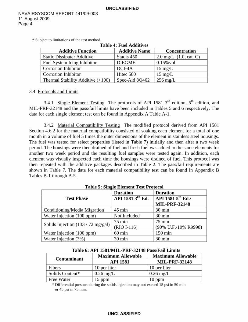
* Subject to limitations of the test method. Table 4: Fuel Additives
Additive Function Additive Name Concentration Static Dissipater Additive Stadis 450 2.0 mg/L (1.0, cat. C) Fuel System Icing Inhibitor DiEGME 0.15%vol Corrosion Inhibitor DCI-4A 15 mg/L Corrosion Inhibitor Hitec 580 15 mg/L Thermal Stability Additive (+100) Spec-Aid 8Q462 256 mg/L
3.4 Protocols and Limits
3.4.1 Single Element Testing The protocols of API 1581 3rd edition, 5th edition, and MIL-PRF-32148 and the pass/fail limits have been included in Tables 5 and 6 respectively. The data for each single element test can be found in Appendix A Table A-1.
3.4.2 Material Compatibility Testing The modified protocol derived from API 1581 Section 4.6.2 for the material compatibility consisted of soaking each element for a total of one month in a volume of fuel 5 times the outer dimensions of the element in stainless steel housings. The fuel was tested for select properties (listed in Table 7) initially and then after a two week period. The housings were then drained of fuel and fresh fuel was added to the same elements for another two week period and the resulting fuel samples were tested again. In addition, each element was visually inspected each time the housings were drained of fuel. This protocol was then repeated with the additive packages described in Table 2. The pass/fail requirements are shown in Table 7. The data for each material compatibility test can be found in Appendix B Tables B-1 through B-5.
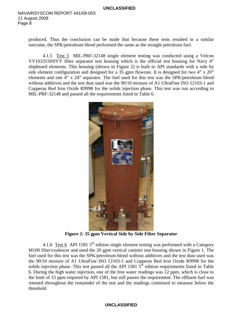
Table 5: Single Element Test Protocol Duration Duration
Test Phase API 1581 3rd Ed. API 1581 5th Ed./ MIL-PRF-32148
Conditioning/Media Migration 45 min 30 min Water Injection (100 ppm) Not Included 30 min
Solids Injection (133 / 72 mg/gal) 75 min (RIO I-116)
75 min (90% U.F./10% R9998)
Water Injection (100 ppm) 60 min 150 min Water Injection (3%) 30 min 30 min
Table 6: API 1581/MIL-PRF-32148 Pass/Fail Limits
Maximum Allowable Maximum Allowable Contaminant API 1581 MIL-PRF-32148 Fibers 10 per liter 10 per liter Solids Content* 0.26 mg/L 0.26 mg/L Free Water 15 ppm 10 ppm
* Differential pressure during the solids injection may not exceed 15 psi in 50 min or 45 psi in 75 min.

UNCLASSIFIED NAVAIRSYSCOM REPORT 441/09-003
11 August 2009 Page 5
UNCLASSIFIED
Table 7: Material Compatibility Pass/Fail Requirements Test Requirement for Failure WSIM < 85 (Test 1) Water Reaction Interface > 1b (Test 1 & 2) and/or Water Reaction Separation > 2 Saybolt Color Decrease by > 4 units (Test 1 & 2) Thermal Stability > 3 or abnormal in nature Existent Gum Increase by 8mg/100mL*
* If existent gum increases by more than 3mg/100mL after the first soak period, the increase during the second soak period shall be less than 50% of the increase measured during the first soak.
4.0 DISCUSSION 4.1 Single Element Testing The single element tests were run using three different types of housings with rated flow rates representative of DoD systems currently in place. Before each test, the test fuel was water washed, clay treated, and prepared with the specified additives as described in Table 1. Including retests, there were a total of twelve single element tests performed. All test data is contained in Appendix A Table A-1.
4.1.1 Test 1 API 1581 3rd edition single element testing was performed using a vertical canister filter separator test housing rated at 20 gpm that is representative of the type used in tactical systems (shown in Figure 1). This housing is designed for one 4” x 20” coalescer element with a slipover separator. The fuel used was the 100% petroleum aviation fuel. After the 45 min element conditioning phase and the solids injection, the low water injection was initiated, but was terminated after 10 min due to passing greater than 15 ppm of free water which fails the requirement for effluent free water as listed in Table 6. The test was not continued further due to the effluent free water failure. The effluent solids content downstream of the element up to this point was unaffected and the differential pressure (dP) across the element was low at 3 psi. The results of the first tests indicated that the separator may not have been set correctly, so a retest was performed using water washed, clay treated, and newly additized fuel. The same test procedures were followed, verifying that the element and separator were installed correctly, only this time the dP across the element rose to 15 psi in 35 min during the solids injection, which fails the requirement listed in Table 6. Solids injection continued until the pressure reached 75 psi, which is the rated pressure the element can withstand, 55 minutes into the phase.

UNCLASSIFIED NAVAIRSYSCOM REPORT 441/09-003 11 August 2009 Page 6
UNCLASSIFIED
Figure 1: 20 gpm Vertical Canister Filter Separator
4.1.2 Test 2 API 1581 3rd edition single element testing was conducted using the 20 gpm
vertical canister test housing shown in Figure 1 and the SPK/petroleum blend. After the element conditioning phase, the solids injection with RIO I-116 was started. After approximately 10 min, the differential pressure across the element reached the pass/fail limit of 15 psi before the specified 50 min. The test was allowed to continue past this point in order to collect more data. After the 75 min solids injection, the element dP was measured at 60 psi. The test continued with the low water injection which resulted in passing free water readings of <15 ppm. The test was finally terminated 10 min into the high water injection because the dP reached 75 psi, which is the rated pressure the element can withstand. It is also noted that at this point the free water reading was above 15 ppm. The effluent solids content downstream of the element throughout the test was below the pass/fail limit shown in Table 6. The test was rerun using the 90/10 mixture of A1 UltraFine ISO 12103-1 and Copperas Red Iron Oxide R9998 test dust instead of the Red Iron Oxide I-116. Because the dP increased so rapidly using the RIO I-116, the effects on filtration using the 90/10 mix (API 1581 5th Ed. standard) was evaluated as a comparison with the initial results of the test. The procedure for the retest remained the same except for this change and the test passed all the requirements.
4.1.3 Test 3 API 1581 3rd edition single element testing was performed using the 20 gpm vertical canister test housing shown in Figure 1 and the SPK/petroleum blend. At approximately 5 min into the solids injection with RIO I-116, the dP reached the 75 psi threshold that the filter can withstand and the solids injection was stopped. The housing was taken offline
UNCLASSIFIED NAVAIRSYSCOM REPORT 441/09-003
11 August 2009 Page 7
UNCLASSIFIED
from the main system because of the rapid rise in pressure. When the housing was put back online with the system, the dP had dropped to 27 psi. Since flow through the test element was stopped, the solids trapped in the filter could have settled or redistributed while the housing was offline, which would explain the decrease in pressure when flow was reintroduced to the element. The decision was made to not continue the solids injection since the pressure had increased so rapidly. Instead, the test was resumed at the low water injection and continued to the high water phase. Only the last free water reading during the high water injection was above the effluent water level of >15 ppm at which point the differential pressure was 56 psi. Effluent solids content throughout the test remained below the pass/fail limit.
4.1.4 Test 4 API 1581 3rd edition single element testing was performed using the 20 gpm vertical canister test housing shown in Figure 1 and the SPK/petroleum blend. After the element conditioning phase, the solids injection with RIO I-116 began, but was terminated after 25 min when the dP across the element reached 15 psi. The test continued with the low and high water injection. The high water phase ended after 10 min when the effluent water level remained above the pass/fail limit of >15 ppm. The dP at this point was recorded at 40.5 psi. Effluent solids content throughout the test was below the pass/fail limit listed in Table 6. The test was rerun using the 90/10 mixture of A1 UltraFine ISO 12103-1 and Copperas Red Iron Oxide R9998 instead of the Red Iron Oxide I-116 for the reasons stated previously. The retest again provided a failure at 25 min into the solids injection due to dP. The test was continued until the dP reached 75 psi which occurred 10 min into the low water injection. At the point when the test was stopped, the free water reading was 12 ppm (just below the pass/fail limit of 15 ppm). After further research and discussions with the filter/coalescer manufacturer, a couple possible explanations have been hypothesized for why the testing with API 1581 3rd edition elements (Table 1 Tests 1-4) failed the requirements due to pressure increase. First, industry research has shown that additives play a role in dirt dispersion in kerosene jet fuel. Additive-free fuel allows some particle agglomeration to take place whereas the common fuel additives that were used in this testing have the tendency to break up these particles into much smaller ones. These finer particles will penetrate the filter media further and cause an increased flow restriction, therefore causing the differential pressure to rise much more rapidly. Another possible reason for increased differential pressure is the method that the test dust is injected into the system. The 3rd edition procedure allowed for the red iron oxide to be added into the system dry which would produce more particle agglomeration before it reached the test element. The procedure used for this program follows the 5th edition protocol which calls for mixing the test dust into the fuel in a large tank and then injecting the slurry into the system. The slurry was mixed using a recirculation pump as well as an impeller for no less than 30 min before being injected. This type of mixing could sufficiently break up any agglomerations of particles before reaching the test element, much more so than simply adding the red iron oxide in dry. While there are a couple possible reasons why the differential pressure increased so rapidly during testing, there is no evidence to suggest that it was the use of the 50/50 blend of SPK and petroleum fuel that led to these failures. Tests 1B and 3 were run under the same conditions with the same additives, the only difference being the type of fuel, and the same type of failure was
UNCLASSIFIED NAVAIRSYSCOM REPORT 441/09-003 11 August 2009 Page 8
UNCLASSIFIED
produced. Thus the conclusion can be made that because these tests resulted in a similar outcome, the SPK/petroleum blend performed the same as the straight petroleum fuel.
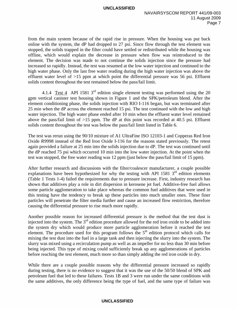
4.1.5 Test 5 MIL-PRF-32148 single element testing was conducted using a Velcon VV1033150NVY filter separator test housing which is the official test housing for Navy 4” shipboard elements. This housing (shown in Figure 2) is built to API standards with a side by side element configuration and designed for a 35 gpm flowrate. It is designed for two 4” x 20” elements and one 4” x 24” separator. The fuel used for this test was the SPK/petroleum blend without additives and the test dust used was the 90/10 mixture of A1 UltraFine ISO 12103-1 and Copperas Red Iron Oxide R9998 for the solids injection phase. This test was run according to MIL-PRF-32148 and passed all the requirements listed in Table 6.
Figure 2: 35 gpm Vertical Side by Side Filter Separator
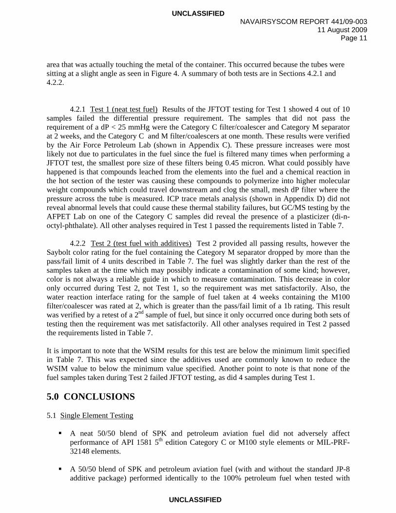
4.1.6 Test 6 API 1581 5th edition single element testing was performed with a Category
M100 filter/coalescer and used the 20 gpm vertical canister test housing shown in Figure 1. The fuel used for this test was the SPK/petroleum blend without additives and the test dust used was the 90/10 mixture of A1 UltraFine ISO 12103-1 and Copperas Red Iron Oxide R9998 for the solids injection phase. This test passed all the API 1581 5th edition requirements listed in Table 6. During the high water injection, one of the free water readings was 12 ppm, which is close to the limit of 15 ppm required by API 1581, but still passes the requirement. The effluent fuel was retested throughout the remainder of the test and the readings continued to measure below the threshold.

UNCLASSIFIED NAVAIRSYSCOM REPORT 441/09-003
11 August 2009 Page 9
UNCLASSIFIED
4.1.7 Test 7 API 1581 5th edition single element testing was conducted with a Category C filter/coalescer and used an Aircraft Appliances and Equipment Ltd, 710994 filter separator test housing, built to API standards and designed for a 45.5 gpm flowrate (shown in Figure 3). This housing is configured for one 6” x 20” coalescer and one 6” x 7” separator side by side and is the official test housing for Navy 6 inch shipboard elements. This test passed all the API 1581 5th edition requirements listed in Table 6. The fuel used for this test was the SPK/petroleum blend without additives and the test dust used was the 90/10 mixture of A1 UltraFine ISO 12103-1 and Copperas Red Iron Oxide R9998 for the solids injection phase.
Figure 3: 45.5 gpm Vertical Side by Side Filter Separator
4.1.8 Test 8 API 1581 5th edition single element testing was conducted using the Army
test housing shown in Figure 1 and the SPK/petroleum fuel. The Category M100 filter/coalescer was tested using fully additized fuel as described in Table 1, which included Spec-Aid8Q462. During the solids injection, the test narrowly missed passing the differential pressure requirement of 15 psi in 50 min. The dP crept up to 15 psi at approximately 40 min into this phase. The test was allowed to continue and maintained solids and water removal during the low water injection, but during the high water injection the effluent free water measured above the pass/fail limit of 15 ppm described in Table 6. Since the results were on the threshold of passing, Test 8 was rerun. The test was rerun using water washed, clay treated, and newly additized fuel and the results produced were almost identical to the first run. The dP rose to 15 psi in 45 min and subsequently allowed greater than 15 ppm of free water to pass during the high water injection. Further research and discussions with the filter/coalescer manufacturer did not produce any concrete reasons as to why there was a gradual rise in pressure during the solids injection. The

UNCLASSIFIED NAVAIRSYSCOM REPORT 441/09-003 11 August 2009 Page 10
UNCLASSIFIED
only difference between Test 8 and Test 6 was the use of approved JP-8+100 additives. Test 6 passed the API test requirments and Test 8 did not, so the conclusion can be made that the SPK/petroleum blend was not the cause for failure because the fuel was used in both tests. Also, because the results were just below the differential pressure requirements of API 1581 5th edition, it should be noted that if the required amount of solids during a test were being injected into a fielded system, the pressure increase would have triggered a change out of the elements before off-spec fuel would have been passed downstream of the filter separator. 4.2 Material Compatibility Testing Each material compatibility test was performed using the 50% blend of SPK and petroleum fuel. Before testing, the fuel was water washed, clay treated, and tested to ensure that the fuel was clean, dry, and additive free. Each stainless steel housing (shown in Figures 4 and 5) was soaked in the test fuel for approximately 24 hours and then rinsed with fuel before the test began. The fuel used for the material compatibility testing was stored in sealed, epoxy-lined 55 gallon drums. This ensured that each round of testing began with the same baseline fuel. Figure 4: 4 inch element housings Figure 5: 6 inch element housing Once the testing with neat fuel was complete, the baseline fuel was doped with the appropriate additives required for each type of filter as described in Table 2. During this second set of testing, it should be noted that the first set of samples taken at the two week point were inadvertently discarded before the test was complete. Due to time constraints, the test was not restarted, but continued as the test plan described for the full month, with new test fuel being added to the elements. The results from the material compatibility tests are shown in Appendix B Table B-1 through Table B-5. During the course of Test 1 (neat test fuel) and Test 2 (additized test fuel), there were no apparent visual differences in appearance or color between the elements being tested and new elements except for a slight discoloration of the outer cloth material of the filter/coalescers on the
UNCLASSIFIED NAVAIRSYSCOM REPORT 441/09-003
11 August 2009 Page 11
UNCLASSIFIED
area that was actually touching the metal of the container. This occurred because the tubes were sitting at a slight angle as seen in Figure 4. A summary of both tests are in Sections 4.2.1 and 4.2.2.
4.2.1 Test 1 (neat test fuel) Results of the JFTOT testing for Test 1 showed 4 out of 10 samples failed the differential pressure requirement. The samples that did not pass the requirement of a dP < 25 mmHg were the Category C filter/coalescer and Category M separator at 2 weeks, and the Category C and M filter/coalescers at one month. These results were verified by the Air Force Petroleum Lab (shown in Appendix C). These pressure increases were most likely not due to particulates in the fuel since the fuel is filtered many times when performing a JFTOT test, the smallest pore size of these filters being 0.45 micron. What could possibly have happened is that compounds leached from the elements into the fuel and a chemical reaction in the hot section of the tester was causing these compounds to polymerize into higher molecular weight compounds which could travel downstream and clog the small, mesh dP filter where the pressure across the tube is measured. ICP trace metals analysis (shown in Appendix D) did not reveal abnormal levels that could cause these thermal stability failures, but GC/MS testing by the AFPET Lab on one of the Category C samples did reveal the presence of a plasticizer (di-n-octyl-phthalate). All other analyses required in Test 1 passed the requirements listed in Table 7.
4.2.2 Test 2 (test fuel with additives) Test 2 provided all passing results, however the Saybolt color rating for the fuel containing the Category M separator dropped by more than the pass/fail limit of 4 units described in Table 7. The fuel was slightly darker than the rest of the samples taken at the time which may possibly indicate a contamination of some kind; however, color is not always a reliable guide in which to measure contamination. This decrease in color only occurred during Test 2, not Test 1, so the requirement was met satisfactorily. Also, the water reaction interface rating for the sample of fuel taken at 4 weeks containing the M100 filter/coalescer was rated at 2, which is greater than the pass/fail limit of a 1b rating. This result was verified by a retest of a 2nd sample of fuel, but since it only occurred once during both sets of testing then the requirement was met satisfactorily. All other analyses required in Test 2 passed the requirements listed in Table 7.
It is important to note that the WSIM results for this test are below the minimum limit specified in Table 7. This was expected since the additives used are commonly known to reduce the WSIM value to below the minimum value specified. Another point to note is that none of the fuel samples taken during Test 2 failed JFTOT testing, as did 4 samples during Test 1. 5.0 CONCLUSIONS 5.1 Single Element Testing
A neat 50/50 blend of SPK and petroleum aviation fuel did not adversely affect performance of API 1581 5th edition Category C or M100 style elements or MIL-PRF-32148 elements.
A 50/50 blend of SPK and petroleum aviation fuel (with and without the standard JP-8
additive package) performed identically to the 100% petroleum fuel when tested with

UNCLASSIFIED NAVAIRSYSCOM REPORT 441/09-003 11 August 2009 Page 12
UNCLASSIFIED
API 1581 3rd edition style elements. Both the SPK/petroleum blend and the straight petroleum based fuel failed performance testing due to exceeding the differential pressure requirement during the solids injection.
A 50/50 blend of SPK and petroleum aviation fuel with the JP-8+100 additive package failed API 1581 5th edition Category M100 performance testing due to exceeding the differential pressure requirement during the solids injection. Test results indicate the 50/50 blend was not the cause for failure because the identical test with the neat 50/50 blend passed the API requirements.
5.2 Material Compatibility Testing
Compatibility testing of a 50/50 blend of SPK and petroleum aviation fuel containing the standard JP-8 additive package and API 1581 3rd edition and 5th edition Category C, M, and M100 elements showed no impact to fuel properties or element integrity.
Compatibility testing of a neat 50/50 blend of SPK and petroleum aviation fuel and API
1581 5th edition Category M100 and 3rd edition elements showed no impact on fuel properties or element integrity.
Compatibility testing of a neat 50/50 blend of SPK and petroleum aviation fuel and API
1581 5th edition Category M and C elements adversely impacted fuel thermal stability, however there was no impact to element integrity.
6.0 RECOMMENDATIONS
Further single element testing on API 1581 3rd Ed style elements with fuel containing military additives should not be considered. These elements were never approved for use with these additives and future testing is expected to yield similar failing results.
Further material compatibility testing with a 50/50 blend of SPK and petroleum aviation
fuel with API 1581 Category M and C filter/coalescers and separators should be considered. This would include a retest of the element soak and corresponding fuel property analysis.
The particle dispersion effects of a 50/50 blend of SPK and petroleum aviation fuel as
well as straight petroleum aviation fuel should be evaluated. Particle size distribution of the test dust in each type of fuel should be investigated to determine if there is a difference due to fuel composition and/or use of approved additives.

UNCLASSIFIED NAVAIRSYSCOM REPORT 441/09-003
11 August 2009 Page 13
UNCLASSIFIED
7.0 REFERENCES
1. API 1581 Third Edition, Specifications and Qualification Procedures for Aviation Jet Fuel Filter/Separators. American Petroleum Institute: Washington, DC. May 1989.
2. API/IP 1581 Fifth Edition, Specifications and Qualification Procedures for Aviation Jet
Fuel Filter/Separators. American Petroleum Institute and The Institute of Petroleum: London. July 2002.
3. MIL-DTL-83133, Detail Specification, Turbine Fuels, Aviation, Kerosene Types, NATO
F-34 (JP-8), NATO F-35, and JP-8+100, dated 1 April 1999.
4. MIL-PRF-32148, Performance Specification, Filter Separator Elements, Fluid, Pressure, Aviation and Distillate Fuel, Naval Shipboard, dated 25 July 2005.

UNCLASSIFIED NAVAIRSYSCOM REPORT 441/09-003 11 August 2009 Page 14
UNCLASSIFIED
Page intentionally left blank

UN
CLA
SSIFIED
NA
VA
IRS
YS
CO
M R
EP
OR
T 441/09-003 11 A
ugust 2009 P
age A-1 of 2
U
NC
LASSIFIED
Appendix A
– Filter Coalescer Perform
ance Test R
esults
Time to Fail
(min into section)
10
35
10
-
5
25
25
-
-
-
40
45
Test Failure Section
2nd Low Water
Solids Inj. Pressure
Solids Inj. Pressure
-
Solids Inj. Pressure
Solids Inj. Pressure
Solids Inj. Pressure
-
-
-
Solids Inj. Pressure
Solids Inj. Pressure
Max High Water (ppm)
-
-
>15
4.5
>15
>15
-
1.5
12
2
>15
>15
Max Low
Water (ppm)
>15
-
2
1
2
2.5
12
1.5
1.5
1.5
5
2
Max Effluent Solids (mg/L)
0.12
0.19
0.14
0.14
0.07
0.08
0.15
0.03
0.14
0.09
0.19
0.2
Max Low
Water (ppm)
-
-
-
-
-
-
-
1
1
1.5
3
2
Fibers (#)
2
0
1
0
1
1
0
4
1
0
3
2
Additives
Stadis 450, Hitec 580
Stadis 450, Hitec 580
N/A
N/A
Stadis 450, Hitec 580
Stadis 450, DCI-4A, DiEGME
Stadis 450, DCI-4A, DiEGME
N/A
N/A
N/A
Stadis 450, DCI-4A, DiEGME, Spec-Aid 8Q462 Stadis 450, DCI-4A, DiEGME, Spec-Aid 8Q462
Fuel
Pet.
Pet.
SPK/Pet. SPK/Pet. SPK/Pet. SPK/Pet. SPK/Pet. SPK/Pet. SPK/Pet. SPK/Pet. SPK/Pet. SPK/Pet.
Solids Type
RIO I-116
RIO I-116
RIO I-116
U.F./R9998
RIO I-116
RIO I-116
U.F./R9998
U.F./R9998
U.F./R9998
U.F./R9998
U.F./R9998
U.F./R9998
Element Type
I-42087
I-42087
I-42087
I-42087
I-42087
I-42087
I-42087
I-420MMF
I-420A4
TC-CO131
I-420A4
I-420A4
Table A-1: Single Element Test Data
Test #
1A
1B
2A
2B
3
4A
4B
5
6
7
8A
8B

UNCLASSIFIED NAVAIRSYSCOM REPORT 441/09-003 11 August 2009 Page A-2 of 2
UNCLASSIFIED
Page intentionally left blank

UNCLASSIFIED NAVAIRSYSCOM REPORT 441/09-003
11 August 2009 Page B-1 of 4
UNCLASSIFIED
Appendix B: Material Compatibility Test Results
Table B-1: 3rd Ed. Style Filter/Coalescer Compatibility Results (Elem. I-42087) Water Reaction Saybolt
Color Thermal Stability Existent Gum
(mg/100mL) Visual Inspection Test
Time (hr) MSEP Int. Sep. Tube Rating dP (mmHg)
1. (blend w/o addit.)
Initial 0 100 1 1 25 1 0.0 0.0 336 98 1 1 26 <1 0.0 0.4 Localized discoloration Diff. -2 0 0 +1 n/a 0.0 +0.4 due to contact w/ housing Second 0 100 1 1 25 1 0.0 0.0 336 97 1 1 26 1 0.0 0.8 Localized discoloration Diff. -3 0 0 +1 n/a 0.0 +0.8 due to contact w/ housing 2. (blend w/ addit.)
Initial 0 65 1 1 25 <1 0.1 2.8 336 - - - - - - - Localized discoloration Diff. -- -- -- -- -- -- -- due to contact w/ housing Second 0 65 1 1 25 <1 0.1 2.8 336 58 1 1 26 <1 0.0 1.4 Localized discoloration Diff. -7 0 0 +1 n/a -0.1 -1.4 due to contact w/ housing
Table B-2: Category M Filter/Coalescer Compatibility Results (Elem. I-420MMF)
Water Reaction Saybolt Color
Thermal Stability Existent Gum (mg/100mL) Visual Inspection
Test Time (hr) MSEP Int. Sep. Tube Rating dP (mmHg)
1. (blend w/o addit.)
Initial 0 100 1 1 25 1 0.0 0.0 336 99 1 1 25 <1 0.0 2.4 Localized discoloration Diff. -1 0 0 0 n/a 0.0 +2.4 due to contact w/ housing Second 0 100 1 1 25 1 0.0 0.0 336 89 1 1 26 1 280.0 0.2 Localized discoloration Diff. -11 0 0 +1 n/a +280.0 +0.2 due to contact w/ housing 2. (blend w/ addit.)
Initial 0 65 1 1 25 <1 0.0 2.8 336 - - - - - - - Localized discoloration Diff. -- -- -- -- -- -- -- due to contact w/ housing Second 0 65 1 1 25 <1 0.0 2.8 336 57 1 1 26 <1 0.1 1.8 Localized discoloration Diff. -8 0 0 +1 n/a +0.1 -1.0 due to contact w/ housing

UNCLASSIFIED NAVAIRSYSCOM REPORT 441/09-003 11 August 2009 Page B-2 of 4
UNCLASSIFIED
Table B-3: Category M100 Filter/Coalescer Compatibility Results (Elem. I-420A4) Water Reaction Saybolt
Color Thermal Stability Existent Gum
(mg/100mL) Visual Inspection Test
Time (hr) MSEP Int. Sep. Tube Rating dP (mmHg)
1. (blend w/o addit.)
Initial 0 100 1 1 25 1 0.0 0.0 336 97 1 1 26 1 0.3 2.0 Localized discoloration Diff. -3 0 0 +1 n/a +0.3 +2.0 due to contact w/ housing Second 0 100 1 1 25 1 0.0 0.0 336 100 1 1 26 1 0.0 0.2 Localized discoloration Diff. 0 0 0 +1 n/a 0.0 +0.2 due to contact w/ housing 2. (blend w/ addit.)
Initial 0 42 1b 1 27 <1 0.0 3.4 336 46 1b 2 26 <1 0.0 4.0 Localized discoloration Diff. +4 0 +1 -1 n/a 0.0 +0.6 due to contact w/ housing Second 0 42 1b 1 27 <1 0.0 3.4 336 49 2 2 26 1 0.0 5.6 Localized discoloration Diff. +7 +1 +1 -1 n/a 0.0 +2.2 due to contact w/ housing
Table B-4: Category M Separator Compatibility Results (Elem. SS424Z)
Water Reaction Saybolt Color
Thermal Stability Existent Gum (mg/100mL) Visual Inspection
Test Time (hr) MSEP Int. Sep. Tube Rating dP (mmHg)
1. (blend w/o addit.)
Initial 0 100 1 1 25 1 0.0 0.0 336 100 1 1 25 1 280.0 0.8 OK Diff. 0 0 0 0 n/a +280.0 +0.8 Second 0 100 1 1 25 1 0.0 0.0 336 100 1 1 24 <1 11.8 0.0 OK Diff. 0 0 0 -1 n/a +11.8 0.0 2. (blend w/ addit.)
Initial 0 65 1 1 25 <1 0.0 2.8 336 - - - - - - - OK Diff. -- -- -- -- -- -- -- Second 0 65 1 1 25 <1 0.0 2.8 336 58 1 1 18 <1 2.2 1.8 OK Diff. -7 0 0 -7 0 +2.2 -1.0

UNCLASSIFIED NAVAIRSYSCOM REPORT 441/09-003
11 August 2009 Page B-3 of 4
UNCLASSIFIED
Table B-5: Category C Filter/Coalescer Compatibility Results (Elem. TC-CO131)
Water Reaction Saybolt Color
Thermal Stability Existent Gum (mg/100mL) Visual Inspection
Test Time (hr) MSEP Int. Sep. Tube Rating dP (mmHg)
1. (blend w/o addit.)
Initial 0 100 1 1 25 1 0.0 0.0 336 91 1 1 26 1 280.0 4.8 OK Diff. -9 0 0 +1 n/a +280.0 +4.8 Second 0 100 1 1 25 1 0.0 0.0 336 88 1 1 25 1 153.0 0.4 OK Diff. -12 0 0 0 n/a +153.0 +0.4 2. (blend w/ addit.)
Initial 0 45 1 1 25 <1 0.1 1.4 336 - - - - - - - OK Diff. -- -- -- -- -- -- -- Second 0 45 1 1 25 <1 0.1 1.4 336 * 1 1 26 <1 0.0 1.2 OK Diff. -- 0 0 +1 n/a -0.1 -0.2
* Not enough sample to perform analysis

UNCLASSIFIED NAVAIRSYSCOM REPORT 441/09-003 11 August 2009 Page B-4 of 4
UNCLASSIFIED
Page intentionally left blank

UNCLASSIFIED NAVAIRSYSCOM REPORT 441/09-003
11 August 2009 Page C-1 of 4
UNCLASSIFIED
Appendix C: JFTOT Results from AFPET Laboratory

UNCLASSIFIED NAVAIRSYSCOM REPORT 441/09-003 11 August 2009 Page C-2 of 4
UNCLASSIFIED

UNCLASSIFIED NAVAIRSYSCOM REPORT 441/09-003
11 August 2009 Page C-3 of 4
UNCLASSIFIED

UNCLASSIFIED NAVAIRSYSCOM REPORT 441/09-003 11 August 2009 Page C-4 of 4
UNCLASSIFIED

UNCLASSIFIED NAVAIRSYSCOM REPORT 441/09-003
11 August 2009 Page D-1 of 1
UNCLASSIFIED
Appendix D: Results from Inductively Coupled Plasma Analysis
Table D-1: Results from ICP Metals Analysis on Material Compatibility Samples
Test Initial SPK blend
w/o addit.
Cat. M F/C 1 month sample
w/o addit.
Cat. M Sep. 2 week sample w/o
addit.
Cat. C F/C 2 week sample w/o
addit.
Cat. C F/C 1 month sample
w/o addit. Units
Aluminum 0.022 <0.021 <0.021 <0.021 <0.021 ppm
Barium <0.002 <0.002 <0.002 <0.002 <0.002 ppm
Boron 0.065 0.023 <0.023 <0.023 0.027 ppm
Cadmium 0.017 <0.009 <0.009 <0.009 <0.009 ppm
Calcium 0.013 0.006 0.016 0.012 0.015 ppm
Chromium <0.007 <0.007 <0.007 <0.007 <0.007 ppm
Copper 0.002 <0.002 0.022 <0.002 <0.002 ppm
Iron <0.004 <0.004 0.004 <0.004 <0.004 ppm
Lead <0.033 <0.033 <0.033 <0.033 <0.033 ppm
Lithium 0.035 0.026 0.027 0.025 0.028 ppm
Magnesium 0.002 0.001 0.003 0.001 0.001 ppm
Manganese 0.001 <0.001 <0.001 <0.001 <0.001 ppm
Molybdenum <0.029 <0.029 <0.029 <0.029 <0.029 ppm
Nickel <0.020 <0.020 <0.020 <0.020 <0.020 ppm
Phosphorus <0.027 <0.027 <0.027 <0.027 <0.027 ppm
Potassium <0.048 <0.048 <0.048 <0.048 <0.048 ppm
Silicon 0.133 0.237 0.104 12.1 1.83 ppm
Silver 0.015 0.004 0.005 <0.004 0.006 ppm
Sodium 0.654 0.400 0.485 0.394 0.451 ppm
Tin <0.074 <0.074 <0.074 <0.074 <0.074 ppm
Titanium <0.002 <0.002 <0.002 <0.002 <0.002 ppm
Vanadium 0.003 <0.002 <0.002 <0.002 <0.002 ppm
Zinc 0.008 <0.005 0.005 0.015 <0.005 ppm

REPORT DOCUMENTATION PAGE Form Approved
OMB No. 0704-0188 Public reporting burden for this collection of information is estimated to average 1 hour per response, including the time for reviewing instructions, searching existing data sources, gathering and maintaining the data needed, and completing and reviewing this collection of information. Send comments regarding this burden estimate or any other aspect of this collection of information, including suggestions for reducing this burden to Department of Defense, Washington Headquarters Services, Directorate for Information Operations and Reports (0704-0188), 1215 Jefferson Davis Highway, Suite 1204, Arlington, VA 22202-4302. Respondents should be aware that notwithstanding any other provision of law, no person shall be subject to any penalty for failing to comply with a collection of information if it does not display a currently valid OMB control number. PLEASE DO NOT RETURN YOUR FORM TO THE ABOVE ADDRESS. 1. REPORT DATE (DD-MM-YYYY) 11-08-2009
2. REPORT TYPE Technical Report
3. DATES COVERED (From - To) 1-09-2008 to 30-01-2009
4. TITLE AND SUBTITLE Evaluation of the Impact of a Synthetic Paraffinic Kerosene
5a. CONTRACT NUMBER N/A
And JP-8 Blend on the Filters and Filter/Coalescer Performance 5b. GRANT NUMBER N/A
5c. PROGRAM ELEMENT NUMBER N/A
6. AUTHOR(S) Domen, Michael; Author
5d. PROJECT NUMBER N/A
Kamin, Richard A; Editor
5e. TASK NUMBER N/A
Mearns, Douglas F; Editor
5f. WORK UNIT NUMBERN/A
7. PERFORMING ORGANIZATION NAME(S) AND ADDRESS(ES)
8. PERFORMING ORGANIZATION REPORT NUMBER
Naval Fuels & Lubricants Cross Functional Team 22229 Elmer Road Patuxent River, MD 20670-1534
NF&LCFT REPORT 441/09-003
9. SPONSORING / MONITORING AGENCY NAME(S) AND ADDRESS(ES) 10. SPONSOR/MONITOR’S ACRONYM(S) USAF AFFCO, 77 AESW Chief of Naval Operations N43 N/A 145 Mondahan Way, Bldg 28 2511 Jefferson Davis Highway Wright Patterson AFB OH Arlington VA 22202 11. SPONSOR/MONITOR’S REPORT 45433 NUMBER(S) N/A 12. DISTRIBUTION / AVAILABILITY STATEMENT A Approved for public release; distribution is unlimited.
13. SUPPLEMENTARY NOTES N/A
14. ABSTRACT Synthetic Paraffinic Kerosene (SPK) is a liquid hydrocarbon fuel which can be produced by several different methods, one of which being the Fischer Tropsch (FT) process. Since 70 percent of the petroleum currently used in the U.S. is imported and SPK can be produced from domestic hydrocarbon sources such as coal and natural gas, certification of SPK for use as a blending component in JP-8 fuel is being pursued to enhance US energy security. This program evaluated the effects of a 50/50 blend of SPK and petroleum aviation fuel with and without the standard JP-8 additive package on filter/coalescer performance. The filter/coalescer elements tested were representative of those currently used in military and commercial filtration systems. The presence of the SPK blending component in the fuel did not impact the performance of the filter/coalescer elements.
15. SUBJECT TERMS SPK, Synthetic Paraffinic Kerosene, FT Fuel, Fischer-Tropsch Aviation Fuel, Alternate Aviation Fuel, Coalescer Performance
16. SECURITY CLASSIFICATION OF:
17. LIMITATION OF ABSTRACT
18. NUMBER OF PAGES
19a. NAME OF RESPONSIBLE PERSON Douglas F. Mearns
a. REPORT UNCLASSIFIED
b. ABSTRACT UNCLASSIFIED
c. THIS PAGE UNCLASSIFIED
Unclassified Unlimited
34
19b. TELEPHONE NUMBER (include area code) 301-757-3421
Standard Form 298 (Rev. 8-98) Prescribed by ANSI Std. Z39.18