evaluation of steering angles through four bar link …
TRANSCRIPT
EVALUATION OF STEERING ANGLES THROUGH FOUR BAR LINK MECHANISM
VENKATESH SANKARAMANCHI B TECH, DEPARTMENT OF MECHANICAL ENGINEERING,
VELAGAPUDI RAMAKRISHNA SIDDHARTHA ENGINEERING COLLEGE, INDIA Under guidence of DR N.RAVI KUMAR
PROFESSOR , DEPARTMENT OF MECHANICAL ENGINEERING, VELAGAPUDI RAMAKRISHNA SIDDHARTHA ENGINEERING COLLEGE, INDIA
ABSTRACT;It would take a long time to find steering angles through theoretical method or by drawing
four bar mechanism in a CAD software and to find steering angles through them. The present solution for
this problem is to develop a programme, so that by giving basic inputs we would get the result of steering
angles. The main objective of this paper is to explain how to develop a programming code for finding
steering angles and comparing the results with theoretical and CAD model solution.
KEYWORDS ; steering arm , trackrod, c to c distance, input angle, out put angle, Ackermann angle,
steering angle
—————————— ——————————
1. INTRODUCTION There is been well known theoretical method to
find the steering angles, in which some formulae
is used for finding the angles. Further method to
find the steering angles is by using cad model.
which is done as following, In basic every
steering mechanism (either Ackermann or
Devis) is inversion of four bar or six bar
mechanism. Now let us define constraints of
steering to basic four bar link mechanism and
develop a CAD model to it . An another method
is developed from the cad model in which a
programming code is developed to find the
steering angles. The programming code can be
developed easily once model is developed.
2. THEORETICAL METHOD
Theoretical method for finding steering angles
includes developing of formulae using
instantaneous centre method as shown in below
figure.
The distance b/w c bracket to c bracket is
assumed as c , trackrod length is assumed as l
and steering arm length is assumed as k and θ is
inner angle and φ is outer angle and α is
Ackermann angle
International Journal of Scientific & Engineering Research Volume 11, Issue 1, January-2020 ISSN 2229-5518
617
IJSER © 2020 http://www.ijser.org

From figure it is clear that sin(α)=(c-l)/2r=y/r
And also sin(θ + α) + sin(α – φ)=2y/r=2sin(α)
Now let us assume
Length of front axle=300cm (c to c distance)
Length of steering arm =120cm
Length of track rod =250cm
Now we will find the output angles from each
input angle (varying from I to n)
Sol
Sin(α)=(300-250)/2*120=12.02 degrees
Now a table is drawn for showing results of
output angles for each input angle
By using formulae sin(θ + α) + sin(α – φ)=2sin(α)
θ Input angle (θ + α)
Output angle( α – φ)
φ
0 12.02 12.02 0
1 13.02 11.0237 1.0037
3 15.02 9.0531 2.966
5 17.02 7.111 4.908
10 22.02 2.3828 9.6372
15 27.02 92.166 80.146
3. CAD MODEL
It is very simple to draw a 4 bar link mechanism
sketch in any cad software .Since it is easy for
me to use catia software I adapted it.
Now let us assume
1. fixed link as distance b/w c bracket to c
bracket(front axle)
2. the crank as steering arm
3. connecting rod as track rod
if these inputs were given and by giving
input angle we would get output angle.
The resultant Ackermann angle is angle
for which the difference b/w input and
output angle is nearly equals to zero.
The below mentioned figure can be
assumed as follows
Dotted line; It is assumed as the
distance b/w the C bracket to C
bracket(front axle).
Inclined line; It is assumed as the length
of steering arm.
Horizontal line; It is assumed as the
track rod length.
Input angle ; It is assumed as the angle
b/w the inclined line located at left side
with vertical.
International Journal of Scientific & Engineering Research Volume 11, Issue 1, January-2020 ISSN 2229-5518
618
IJSER © 2020 http://www.ijser.org

output angle ; It is assumed as the
angle b/w the inclined line located at
rigth side with vertical.
While construction it is checked
carefully that length and position of
front axle is fully constrained, length of
steering arm and length of track rod are
constrained .
And also it is essential to make those
vertical lines as axis.
Now by giving different input angles we would
get different output angles since position of
track rod is not constrained. Each input angle,
output angle and also the difference b/w them
is noted.
The input angle for which least difference is
obtained is chosen as the Ackermann angle.
The following is the table containing some of
the input , output angles and difference b/w
them ,if the following constrains are assumed
Length of front axle=300cm
Length of steering arm =120cm
Length of track rod =250cm
INPUT ANGLE
OUTPUT ANGLE
DIFFERENCE
0 24.752 -24.752
5 19.279 -14.279
10 14.068 -4.068
12 12.049 0.049
15 9.088 6.088
20 4.326 16.326
22 2.182 20.182
50 109.108 59.108
I
Now if we observe the table, difference is being
decreased initially as the input angle increases
and at certain point it becomes nearly equals to
zero and increases if further increase in input
angle.
The input angle for which difference is nearly
equals to zero is chosen as Ackermann angle
and knuckle is so manufactured according to
this angle.
In the above table at angle 12 degrees
difference is nearly equals to zero so it is chosen
as Ackermann angle.
C to c
distance
International Journal of Scientific & Engineering Research Volume 11, Issue 1, January-2020 ISSN 2229-5518
619
IJSER © 2020 http://www.ijser.org

Note: while plotting graph only magnitude of
difference is considered neglecting its sign.
The resultant four bar link mechanism figure for
above problem is as follows
This process would definetly takes very long time, so we will develop an programming code following above process so that problem becomes easier.
4. Solution From the cad model result, it is observed that at
resultant Ackermann angle, track rod is located
in b/w c brackets.
From the graph obtained it is clear that the
curve is being decreasing in nature upto the
Ackermann angle .
Let us assume;
1. C to c distance as d
2. Steering arm length as h
3. Trackrod length as k
4. Input angle=r, output angle=s,
difference=t
Let us assume k1 and k2 such that k1+k2=k (k1 is
distance from central axis to left side of trackrod
and k2 is distance from central axis to right side
of trackrod).
From cad model it is concluded that; Sine ratio
of input and output angles can be calculated
from length k1 and k2 as mentioned in below
formulae
Sin(r)= ((d/2)-k1)/h
Sin(s)= ((d/2)-k2)/h
Only if below condition is satisfied
(d/2)-k1>0 && (d/2)-k2>0.
0
10
20
30
40
50
60
70
0 10 20 30 40 50 60
INPUT ANGLE Vs DIFFERENCE
International Journal of Scientific & Engineering Research Volume 11, Issue 1, January-2020 ISSN 2229-5518
620
IJSER © 2020 http://www.ijser.org

(d/2)-k2<0 then input and output angles are
taken as
Sin(r)= ((d/2)-k1)/h
Sin(s)=90 – (((d/2)-k2)/h)
Now by varying k1 from 0 t0 k by satisfying
above condition different input angles(r) and
output angles(s) can be calculated.
Difference b/w the r and s is also calculated and
stored in value t.
All the results of r s and t are printed. Now
result is checked and the value of r for which t is
nearly equals to zero is chosen as Ackermann
angle.
PROGRAMMING CODE
#include<stdio.h>
#include<conio.h>
#include<math.h>
void main()
{
int i;
float r,s,t;
float k,h,d;
float n,m,k1,k2;
printf("enter c to c distance==");
scanf("%f",&d);
printf("\nenter steering arm length==");
scanf("%f",&h);
printf("\nenter track rod lenth==");
scanf("%f",&k);
for(i=0;i<=k;i++)
{
k1=k-k2;
k2=i;
n=(((d/2)-k1)/h);
m=(((d/2)-k2)/h);
if(m>=0&&n>=0)
{
r=asin(n)*180/3.14;
s=asin(m)*180/3.14;
t=r-s;
}
Else if(m<0)
{
r=asin(n)*180/3.14;
d
d/2
K1 K2
r s
International Journal of Scientific & Engineering Research Volume 11, Issue 1, January-2020 ISSN 2229-5518
621
IJSER © 2020 http://www.ijser.org
s=90-(asin(m)*180/3.14);
}
printf("\nr=%f s=%f t=%f\n",r,s,t);
}
getch();
}
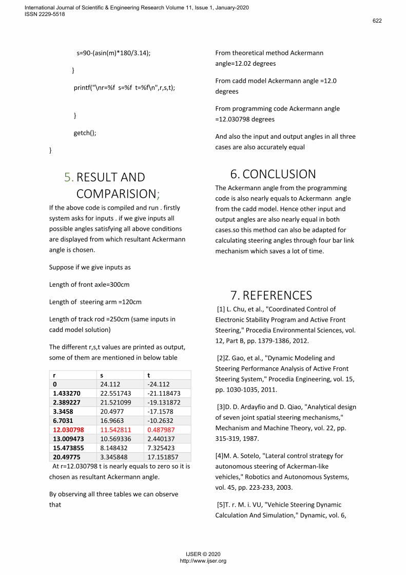
5. RESULT AND COMPARISION;
If the above code is compiled and run . firstly
system asks for inputs . if we give inputs all
possible angles satisfying all above conditions
are displayed from which resultant Ackermann
angle is chosen.
Suppose if we give inputs as
Length of front axle=300cm
Length of steering arm =120cm
Length of track rod =250cm (same inputs in
cadd model solution)
The different r,s,t values are printed as output,
some of them are mentioned in below table
r s t 0 24.112 -24.112
1.433270 22.551743 -21.118473
2.389227 21.521099 -19.131872
3.3458 20.4977 -17.1578
6.7031 16.9663 -10.2632
12.030798 11.542811 0.487987
13.009473 10.569336 2.440137
15.473855 8.148432 7.325423
20.49775 3.345848 17.151857
At r=12.030798 t is nearly equals to zero so it is
chosen as resultant Ackermann angle.
By observing all three tables we can observe
that
From theoretical method Ackermann
angle=12.02 degrees
From cadd model Ackermann angle =12.0
degrees
From programming code Ackermann angle
=12.030798 degrees
And also the input and output angles in all three
cases are also accurately equal
6. CONCLUSION The Ackermann angle from the programming
code is also nearly equals to Ackermann angle
from the cadd model. Hence other input and
output angles are also nearly equal in both
cases.so this method can also be adapted for
calculating steering angles through four bar link
mechanism which saves a lot of time.
7. REFERENCES [1] L. Chu, et al., "Coordinated Control of
Electronic Stability Program and Active Front
Steering," Procedia Environmental Sciences, vol.
12, Part B, pp. 1379-1386, 2012.
[2]Z. Gao, et al., "Dynamic Modeling and
Steering Performance Analysis of Active Front
Steering System," Procedia Engineering, vol. 15,
pp. 1030-1035, 2011.
[3]D. D. Ardayfio and D. Qiao, "Analytical design
of seven joint spatial steering mechanisms,"
Mechanism and Machine Theory, vol. 22, pp.
315-319, 1987.
[4]M. A. Sotelo, "Lateral control strategy for
autonomous steering of Ackerman-like
vehicles," Robotics and Autonomous Systems,
vol. 45, pp. 223-233, 2003.
[5]T. r. M. i. VU, "Vehicle Steering Dynamic
Calculation And Simulation," Dynamic, vol. 6,
International Journal of Scientific & Engineering Research Volume 11, Issue 1, January-2020 ISSN 2229-5518
622
IJSER © 2020 http://www.ijser.org
2012. [6]Z. Zhao and C. Si, "Dynamic analysis of
steering system of the articulated vehicle in the
heeled status," Procedia Engineering, vol. 16,
pp. 540-545, 2011.
[7]F. Chen and G. Genta, "Dynamic modeling of
wheeled planetary rovers: A model based on the
pseudo-coordiates approach," Acta
Astronautica, vol. 81, pp. 288-305, 2012.
[8]B. Maclaurin, "A skid steering model with
track pad flexibility," Journal of Terramechanics,
vol. 44, pp. 95-110, 2007.
[9]V. Malviya and R. Mishra, "Development of
an analytical multi-variable steady-state vehicle
stability model for heavy road vehicles," Applied
Mathematical Modelling.
[10]M. P. O. F. M. d. U. Wasiwitono, "Analisa
Kinematik Spatial untukRack and Pinion
padaKendaraan Multiguna Pedesaan (GEA)," vol.
4, 2013.
[11]B. C. Besselink, "Development of a vehicle to
study the tractive performance of integrated
steering-drive systems," Journal of
Terramechanics, vol. 41, pp. 187-198, 2004.
[12] D. F. Flippo and D. P. Miller, "Turning
efficiency prediction for skid steering via single
wheel testing," Journal of Terramechanics, vol.
52, pp. 23-29, 2014.
[13]B. R. F. a. W. H. Warren, "Behavioral
Dynamics of Steering, Obstacle Avoidance,and
Route Selection," Human Perception and
Performance, vol. 20, 2003.
[14]J. T. Economou and R. E. Colyer, "Fuzzy-
hybrid modelling of an Ackerman steered
electric vehicle," International Journal of
Approximate Reasoning, vol. 41, pp. 343-368,
2006. [15]J. Yao, "The Kinematic Synthesis of
Steering Mechanisms," Mechanisms, vol. 21
International Journal of Scientific & Engineering Research Volume 11, Issue 1, January-2020 ISSN 2229-5518
623
IJSER © 2020 http://www.ijser.org