evaluation of printed-circuit boards materials for high
TRANSCRIPT

HAL Id: hal-01674483https://hal.archives-ouvertes.fr/hal-01674483
Submitted on 2 Jan 2018
HAL is a multi-disciplinary open accessarchive for the deposit and dissemination of sci-entific research documents, whether they are pub-lished or not. The documents may come fromteaching and research institutions in France orabroad, or from public or private research centers.
L’archive ouverte pluridisciplinaire HAL, estdestinée au dépôt et à la diffusion de documentsscientifiques de niveau recherche, publiés ou non,émanant des établissements d’enseignement et derecherche français ou étrangers, des laboratoirespublics ou privés.
Evaluation of printed-circuit boards materials for hightemperature operation
Oriol Aviño Salvado, Wissam Sabbah, Cyril Buttay, Hervé Morel, PascalBevilacqua
To cite this version:Oriol Aviño Salvado, Wissam Sabbah, Cyril Buttay, Hervé Morel, Pascal Bevilacqua. Evaluationof printed-circuit boards materials for high temperature operation. Journal of Microelectronics andElectronic Packaging, International Microelectronics And Packaging Society (IMAPS), 2017, 14 (4),10.4071/imaps.516313. hal-01674483

Evaluation of printed-circuit boards materials for hightemperature operation
Oriol AVINO-SALVADO, Wissam SABBAH, Cyril BUTTAY, Herve MOREL, Pascal BEVILACQUA
Universite de Lyon, F-69621, FranceCNRS, UMR5005, France,
INSA Lyon,Laboratoire Ampere,
batiment L. de Vinci, 21 avenue CapelleF-69621, France
ABSTRACT
This article presents the long term (1000 h) behaviour of two printed-circuit board materials (Panasonic R1755V,a high-TG glass-epoxy composite and Arlon 85N, a polyimide-based laminate) stored at high temperature (190 °C).Tests are performed in air and in nitrogen atmospheres. Electrical and physical measurements are performed regu-larly (once per week).
Almost no degradation is observed for both materials, when stored in nitrogen. On the contrary, the boardstored in air show the consequences of ageing. This is especially true for the glass-epoxy material, which becomesunusable after 2 weeks, because of large swelling.
KeywordsPCB; ageing; polyimide; FR4; oxygen
1 Introduction
Many applications require electronics systems whichcan operate in relatively high temperatures. For exam-ple, in the oil and gas industry, circuits are required tooperate in ambient temperatures of 150 °C, 200 °C, ormore [1]. Depending on their location on the car, auto-motive electronics can experience ambient temperaturesof more than 175 °C [2].
Organic substrates such as epoxy-based Printed Cir-cuit Boards (PCBs) are attractive because of their lowcost (a few C per dm2), process availability (they can besourced from many companies), and because they offera high density of interconnections (50 µm track-widthand thinner). This is especially true for the automotivemarket, where ceramic substrates are often consideredtoo expensive.
High temperature operation is also a key capabilityfor some power electronic systems [3], as they oper-ate in harsh conditions, or because they dissipate a lotof heat (hundreds of W/cm2). Many power electronicchips (diodes and transistors, either made out of sili-con or silicon carbide) are rated for a maximum junctiontemperature of 175 °C. While they are usually mountedon high performance ceramic substrates, not on organicPCBs, these chips require a number of peripheral cir-cuits to be mounted in close vicinity [4]. For example,power MOSFET transistors require some gate drive In-tegrated Circuits (ICs) to operate. Such ICs can oper-
ate at the same junction temperature as the transistorsthey drive, if not higher [5]. However, these periph-eral circuits do not carry as much current nor do theydissipate as much power as the power chips. Therefore,they do not require mounting on ceramic substrates, andtemperature-capable PCBs can be used instead.
Shaddock et al. [6] investigated the behaviour of sev-eral PCB materials at temperatures ranging from 200 to250 °C, over large periods of time (up to 10000 h). Itwas found that protecting the boards from oxygen wasimportant to increase lifetime. This was confirmed byLahokallio et al. [7] who found that PCBs (FR4 andhydrocarbon-ceramic laminate) tested from 200 °C to240 °C suffered strongly from oxidation.
In this paper, we investigate the ageing behaviour ofa more standard material (a high-TG FR4) and compareit to a polyimide-based laminate. The experimental pro-tocol is detailed in the next section. A preliminary ex-periment, presented in section 3, is run to define the testconditions. The results of the tests are presented in sec-tion 4 and discussed in section 5.
2 Experimental Protocol
2.1 Test VehiclesTwo materials were tested: a FR4-type material (Pana-sonic R1755-V, with a Tg > 170 °C) and a polyimide-type (Arlon 85N, Tg > 250 °C). Both materials were

85N R-1755VManufacturer Arlon PanasonicComposition Glass/Polyimide Glass/EpoxyTG 260 °C 172 °CPermittivity 4.39 (1 MHz) 5.4 (1 MHz)z-CTE 50 ppm/K 43 ppm/Kx/y-CTE 16 ppm/K 15 ppm/K
Table 1: Main properties of the polyimide [8] and FR4 lami-nates [9]
Figure 1: Chamber used for isothermal ageing at low oxygenpercentage (<0.1%), using an oxygen monitor and a low flowof nitrogen (0.1 standard litre per minute). The system is 1.4 mtall, 1.2 m wide.
used in the form of 6-layer patterned boards (Processedby Elvia, France), with 70 µm Copper, and 1.6 mm to-tal thickness. Pad finish is Ni/Au (6 µm/80 nm). Thetest vehicles received a solder resist layer on both sides(XV501T, Imagesecure).
The test boards contain 3 groups of features:
• a surface isolation resistance (SIR) pattern, whichis an interdigitated pattern with a 500 µm distancebetween fingers, and 580 mm total finger length.This pattern is biased during the ageing test to pro-duce an electrical field of 25 V/mm [10].
• 32 daisy-chained vias (hole diameter 450 µm);
• 2 planar capacitors (electrodes size 20×20 mm2)to detect any change in thickness of the PCB
For some of the test described below, some test vehi-cles were separated in small coupons (≈ 2×2 cm2) us-ing shears. No damage (e.g. delamination of the edgesof the coupons) was observed after this operation.
2.2 Accelerated ageingAfter a preliminary drying (6 h at 120 °C [11, 12]), thetest vehicles are placed in an oven for isothermal ageing
(storage test). Two test conditions are evaluated in thispaper: ageing in air, using a standard forced-convectionoven (MMM Venticell), or in nitrogen with the systempresented in Fig. 1 (Termolab). This chamber was es-pecially designed for long term testing: it is gas-tight,requiring only a small flow of nitrogen (0.1 SLM) toprevent oxygen to enter. An oxygen monitor is con-nected to the exhaust of the chamber to ensure the oxy-gen concentration remains below 0.1 %, and to injectmore nitrogen if required.
The ageing tests are run for 1008 h (6 weeks).In the ovens, the boards are maintained by edge-
board connectors rated at 200 °C (Vishay EB45-P0K2030X). These connectors are used to bias the SIRpatterns of the boards. Alpha Wire PTFE-insulatedwires enter the ovens and are soldered (HMP alloy) tothe connectors. The reliability of this setup is satisfying,as no failure was observed throughout the tests.
The test temperature was defined through preliminarytests (“step stress tests”) which are presented in sec-tion 3.
2.3 Characterisation
Before the beginning of the ageing test, and then pe-riodically (every week, which corresponds to 168 h),the samples are submitted to the following characterisa-tions:
• Weighting (Ohaus Adventurer Pro 210, 1 mg reso-lution). The samples are dried before the first mea-surement.
• Pphotography with a Leica M205 binocular,equipped with a camera and a save/recall systemwhich allows to use identical settings (lightning,white balance, etc.). This produces consistent im-ages throughout the duration of the ageing tests.
• Electrical measurements: The capacitance patternis measured using an Agilent E4990 impedanceanalyser. A Keithley 2410 source and measure unit(SMU) is used to measure both the resistance ofthe vias daisy chain (with a 4-point connection)and the surface isolation resistance pattern. Thisequipment can indeed measure resistances rangingfrom 100 µΩ up to 200 MΩ.
• Finally, micro-sections are performed on some testcoupons using the following protocol: encapsu-lation in acrylic resin (Buehler Varikleer); cut-ting with a low speed diamond saw; grinding withP1200 paper (60 s); polishing on clothes with6 µm, 3 µm and 1 µm diamond particles (180, 180and 120 s respectively). Final polishing is per-formed with 50 nm colloidal silica (60 s), and thesample is rinsed and dried.

t0 150C 170C 190C 210C 230C 250CTemperature [C]
−10
−8
−6
−4
−2
0
Wei
ghtl
oss
[%]
Polyimide, NitrogenPolyimide, AirFR4, NitrogenFR4, Air
Figure 2: Weight loss measured on PCB coupons during step-stress testing (the test temperature is increased every 24 h, onecoupon is removed from the test chamber after each step to becharacterised). As the coupons are relatively small the non-negligible error (±1 mg) introduced due to the resolution ofthe scale is displayed using error bars.
3 Definition of the Test ConditionsA preliminary experiment was run in order to definethe temperature to be used for the ageing tests: in thisexperiment, 6 coupons of FR4 and polyimide boardsare placed in each of the ovens (air and nitrogen atmo-spheres). Starting at 150 °C (arbitrary value), the tem-perature is then increased by 20 °C every 24 h. For eachstep, a coupon is removed from the oven and weighted.
The results are presented in Fig. 2. No weight lossis observed on the samples up to 210 °C. After 24 h at230 °C, the FR4 coupon stored in air shows a dramaticweight loss (almost 8 %). After 24 h at 250 °C, the FR4coupon stored in nitrogen also exhibits a comparableweight loss. Regarding the polyimide coupons, a non-negligible (although much lower than for FR4) weightloss is observed for the coupon stored in air (1.5 %).
As some weight loss is observed between 210 and230 °C in 24 h (for the FR4 board stored in air), and asour tests are scheduled to run over a much longer period(1000 h), a temperature lower than 210 °C (190 °C, cor-responding to the data point immediately before 210 °Cin Fig. 2) was chosen for the isothermal tests.
4 Test ResultsThe weight loss measurements observed during ageingare presented in Fig. 3. They show a small weight lossafter the first week (168 h) for all boards. This weightloss tends to be larger for polyimide boards. Then, theweight tends to stabilise until 500 h. At that point,the FR4 board stored in air shows a strong weight loss(4.5 %). No further change is observed for the remain-ing 500 h. A small increase in weight is observed forthe polyimide board stored in nitrogen at the end of thetest, and is unexplained (unfortunately, for this measure-
0 200 400 600 800 1000Time [h]
−5
−4
−3
−2
−1
0
Wei
ghtl
oss
[%]
Polyimide, NitrogenPolyimide, AirFR4, NitrogenFR4, Air
Figure 3: Weight loss during isothermal ageing at 190 °C,for polyimide and FR4 boards, tested in air and nitrogen.The error bars corresponding to the measurement error arebarely visible because the boards tested here are much heav-ier (≈ 20 g) than the coupons used in section 3, resulting ina much more accurate measurement with a 1 mg resolutionscale.
0 200 400 600 800 1000Time [h]
0
20
40
60
80
100
120
Cap
acita
nce
[pF]
Polyimide, NitrogenPolyimide, AirFR4, NitrogenFR4, AirPolyimide, Control sampleFR4, Control sample
Figure 4: Capacitance change during isothermal ageing at190 °C, for polyimide and FR4 boards, tested in air and ni-trogen.
ment, we did not use a control sample, so a measure-ment error cannot be ruled-out).
Regarding the change in capacitance (Fig. 4), the re-sults are comparable, with almost no evolution for thepolyimide boards, as well as for the FR4 board storedin nitrogen (two capacitor patterns are monitored perboard, producing two curves in Fig. 4). The initial dif-ference between FR4 and polyimide boards is due to thedifference in dielectric permittivity (εr = 5.4 for FR4,εr = 4.4 for polyimide). For boards of the same mate-rial, the intial difference in capacitance can be attributedto manufacturing tolerances (in particular, the thicknessof the boards is controlled within ± 10 %). The smallchanges over time, especially for the first 168 h, are cor-related with the weight loss.
For the FR4 board stored in air, however, the capac-itance drop is much larger and starts one week sooner

Boa
rdbe
fore
test
1w
eek
2w
eeks
3w
eeks
4w
eeks
5w
eeks
6w
eeks
FR4
air
FR4
air
poly
imid
eai
r
poly
imid
eai
r
FR4
nitr
ogen
poly
imid
eni
-tr
ogen
Tabl
e2:
Phot
ogra
phs
ofth
ete
stve
hicl
esat
vari
ous
stag
esof
agei
ng,f
orFR
4an
dpo
lyim
ide
boar
ds,t
este
din
airo
rin
nitr
ogen
atm
osph
ere
at19
0°C
.Fie
ldof
view
is3.
2x2.
4m
m2
forS
IRim
ages
,2.
2x1.
6m
m2
fort
hevi
as).
0 200 400 600 800 1000Time [h]
78
80
82
84
86
88
90
92
94
96R
esis
tanc
e[m
Ω]
Polyimide, NitrogenPolyimide, AirFR4, NitrogenFR4, Air
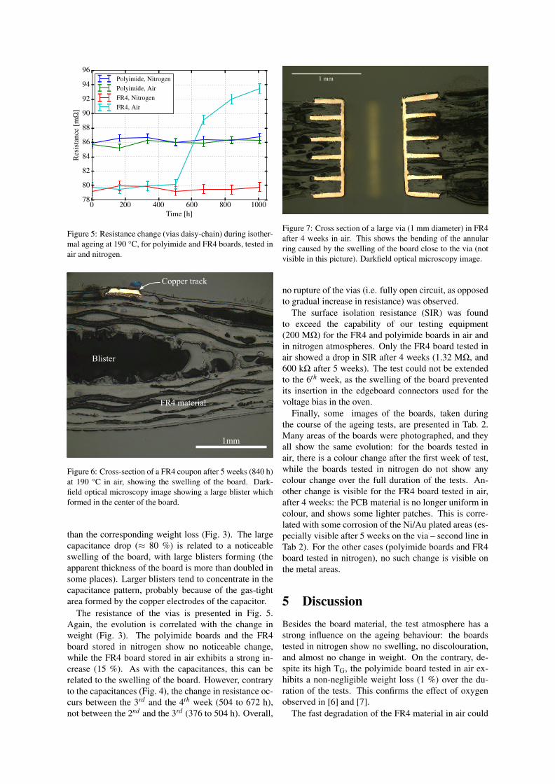
Figure 5: Resistance change (vias daisy-chain) during isother-mal ageing at 190 °C, for polyimide and FR4 boards, tested inair and nitrogen.
1mm
Copper track
FR4 material
Blister
Figure 6: Cross-section of a FR4 coupon after 5 weeks (840 h)at 190 °C in air, showing the swelling of the board. Dark-field optical microscopy image showing a large blister whichformed in the center of the board.
than the corresponding weight loss (Fig. 3). The largecapacitance drop (≈ 80 %) is related to a noticeableswelling of the board, with large blisters forming (theapparent thickness of the board is more than doubled insome places). Larger blisters tend to concentrate in thecapacitance pattern, probably because of the gas-tightarea formed by the copper electrodes of the capacitor.
The resistance of the vias is presented in Fig. 5.Again, the evolution is correlated with the change inweight (Fig. 3). The polyimide boards and the FR4board stored in nitrogen show no noticeable change,while the FR4 board stored in air exhibits a strong in-crease (15 %). As with the capacitances, this can berelated to the swelling of the board. However, contraryto the capacitances (Fig. 4), the change in resistance oc-curs between the 3rd and the 4th week (504 to 672 h),not between the 2nd and the 3rd (376 to 504 h). Overall,
1 mm
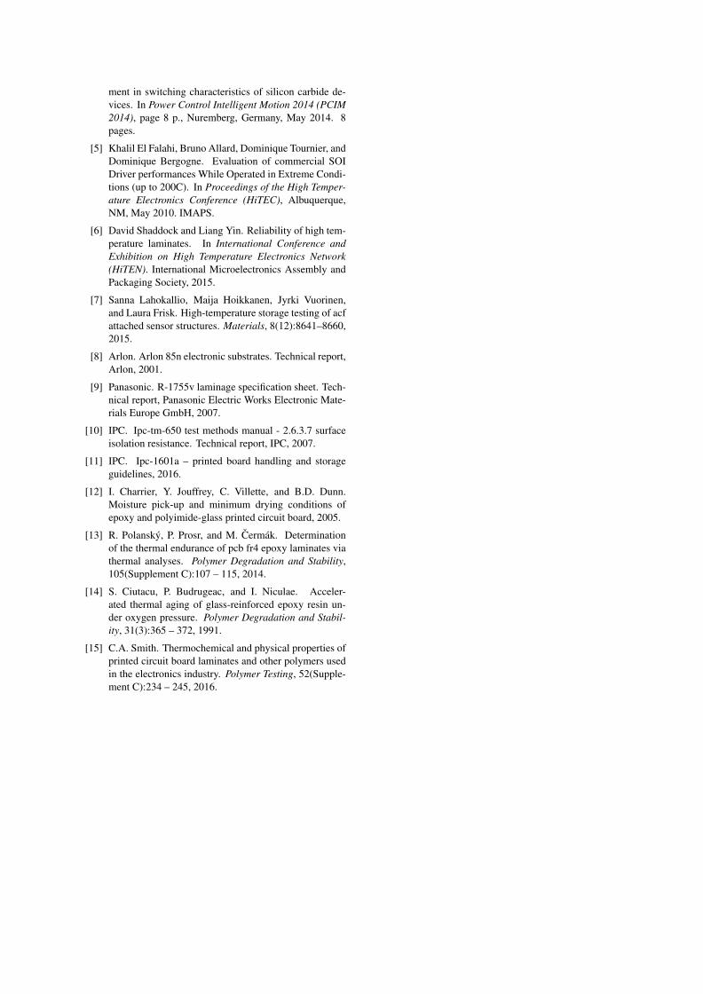
Figure 7: Cross section of a large via (1 mm diameter) in FR4after 4 weeks in air. This shows the bending of the annularring caused by the swelling of the board close to the via (notvisible in this picture). Darkfield optical microscopy image.
no rupture of the vias (i.e. fully open circuit, as opposedto gradual increase in resistance) was observed.
The surface isolation resistance (SIR) was foundto exceed the capability of our testing equipment(200 MΩ) for the FR4 and polyimide boards in air andin nitrogen atmospheres. Only the FR4 board tested inair showed a drop in SIR after 4 weeks (1.32 MΩ, and600 kΩ after 5 weeks). The test could not be extendedto the 6th week, as the swelling of the board preventedits insertion in the edgeboard connectors used for thevoltage bias in the oven.
Finally, some images of the boards, taken duringthe course of the ageing tests, are presented in Tab. 2.Many areas of the boards were photographed, and theyall show the same evolution: for the boards tested inair, there is a colour change after the first week of test,while the boards tested in nitrogen do not show anycolour change over the full duration of the tests. An-other change is visible for the FR4 board tested in air,after 4 weeks: the PCB material is no longer uniform incolour, and shows some lighter patches. This is corre-lated with some corrosion of the Ni/Au plated areas (es-pecially visible after 5 weeks on the via – second line inTab 2). For the other cases (polyimide boards and FR4board tested in nitrogen), no such change is visible onthe metal areas.
5 DiscussionBesides the board material, the test atmosphere has astrong influence on the ageing behaviour: the boardstested in nitrogen show no swelling, no discolouration,and almost no change in weight. On the contrary, de-spite its high TG, the polyimide board tested in air ex-hibits a non-negligible weight loss (1 %) over the du-ration of the tests. This confirms the effect of oxygenobserved in [6] and [7].
The fast degradation of the FR4 material in air could

be expected, as the tests were performed at 190 °C,higher than the TG of the material (170 °C). This degra-dation was detected through all the measurements, butat different times: weight loss (drop after 504 h); capac-itance change (drop after 336 h); via resistance (increaseafter 504 h); SIR (drop after 672 h); visual observation(after 672 h or 4 weeks). Basically, the capacitancemeasurement was the most sensitive measurement. Apossible reason is that the large copper electrodes pre-vented the decomposition gases to permeate, resultingin an accelerated swelling. This swelling then propa-gated over the entire board. Eventually, this made itimpossible to mount the board in the edgeboard connec-tor. The cross section of a FR4 coupon tested in air isvisible in Fig. 6, and shows the extend of the swelling.The formation of blisters is probably a conjunction ofthe rubbery state of the FR4 maintained above its TG,and of the thermo-oxidation of the epoxy caused by thediffusion of oxygen [13]. It might also be related toother compounds included in the polymer, such as bro-mide flame retardant [9], which were found to have adetrimental effect at high temperature in [6]. The grad-ual embritllement of the thermo-oxidized epoxy [14]might also accelerate the delamination of the glass-epoxy composite, expecially above TG, as the CTE ofthe material increases sharply (from 40 to 240 ppm/K inthe z-direction [9]). Although the vias limited some ofthe swelling by clamping the board (see Fig. 7), it canbe seen that their external annular ring is bent. Whileno crack could be observed along the barrel of the vias,such bending might explain the increase in resistancemeasured in Fig. 5.
The FR4 board tested in nitrogen did not show anynoticeable ageing, despite it being stored at 190 °C (i.e.above its TG) for more than 1000 h. Although oper-ating over the glass transition temperature is not rec-ommended because of the reduced mechanical strengthof the board and because of its increased coefficient ofthermal expansion, this might constitute a “low cost”high temperature prototyping platform: to use a stan-dard high-TG FR4 board instead of a more expensivematerial, and then to place it in a dedicated test cham-ber (such as that presented in Fig. 1) to protect it fromoxygen. Another solution, as proposed in [6], could beto use a protection layer such as high temperature pary-lene.
Regarding the polyimide boards, some effects of oxy-gen could be observed (darkening of the solder resistlayer, non-negligible weight loss), but none of these ef-fects translated in changes in electrical performance.
Finally, the Ni/Au finish of the copper tracks wasfound to have a satisfying stability, with no changes inaspect over the duration of the tests, whether in air orin nitrogen, except for the FR4 boards stored in air. Onthe latter, the evolution of the Ni/Au finish is probablydue to its corrosion by the decomposition products ofthe board.
6 ConclusionThe high temperature (190 °C), isothermal ageing ofprinted circuit board materials is presented in this arti-cle. Two materials are investigated, a high-TG FR4 anda polyimide. While polyimide is preferable when oper-ating in air, it is found that FR4 can nonetheless be usedover long periods of time (1000 h), providing the testsare performed in a neutral atmosphere (nitrogen).
Several measurements were performed throughoutthe ageing tests to monitor the condition of the boards.It is found that the capacitance measurements are themost sensitive, as they were the first to detect the degra-dation of the FR4 board tested in air. Overall, the degra-dation could be detected through all the measurements(electrical parameters, weight, or visual inspection), al-beit one to two weeks later.
As it allows the use of standard PCB materials, op-erating in nitrogen atmosphere could be an interestingsolution for lab experiments and prototyping.
Two distinct topics must be addressed to pursuethis study further. First, a more detailed analysis ofthe various elements in the PCB (laminate and solder-resist, mainly) is required. In particular, thermal analy-ses (thermo-gravimetric analysis, differential scanningcalorimetry or thermo-mechanical analysis [15]) willmeasure the degradation temperature of these elementsseparately to better understand the results presented inthis article. The second topic, on the contrary, takesplace at board level. It consists in testing the boards inhumidity and temperature cycling conditions, to reflectmore closely the stresses encountered in real applica-tions.
AcknowledgementsThis work was funded part of the GENOME-PREMICES initiative.
References[1] Robin Beckwith. Downhole Electronic Components:
Achieving Performance Reliability. JPT, pages 42–53,August 2013.
[2] John G. Kassakian and David J. Perreault. The Future ofElectronics in Automobiles. In Proceedings of the Inter-national Symposium on Power Semiconductor Devicesand ICs (ISPSD), pages 15–19, Osaka, Japan, 2001.
[3] Cyril Buttay, Dominique Planson, Bruno Allard, Do-minique Bergogne, Pascal Bevilacqua, Charles Joubert,Mihai Lazar, Christian Martin, Herve Morel, DominiqueTournier, and Christophe Raynaud. State of the art ofhigh temperature power electronics. Materials Scienceand Engineering: B, 176(4):283–288, 2011. Microtech-nology and Thermal Problems in Electronics.
[4] Cyril Buttay, Khalil El Falahi, Remi Robutel, StanislasHascoet, Christian Martin, Bruno Allard, and C. John-son, Mark. Integrated packaging allows for improve-
ment in switching characteristics of silicon carbide de-vices. In Power Control Intelligent Motion 2014 (PCIM2014), page 8 p., Nuremberg, Germany, May 2014. 8pages.
[5] Khalil El Falahi, Bruno Allard, Dominique Tournier, andDominique Bergogne. Evaluation of commercial SOIDriver performances While Operated in Extreme Condi-tions (up to 200C). In Proceedings of the High Temper-ature Electronics Conference (HiTEC), Albuquerque,NM, May 2010. IMAPS.
[6] David Shaddock and Liang Yin. Reliability of high tem-perature laminates. In International Conference andExhibition on High Temperature Electronics Network(HiTEN). International Microelectronics Assembly andPackaging Society, 2015.
[7] Sanna Lahokallio, Maija Hoikkanen, Jyrki Vuorinen,and Laura Frisk. High-temperature storage testing of acfattached sensor structures. Materials, 8(12):8641–8660,2015.
[8] Arlon. Arlon 85n electronic substrates. Technical report,Arlon, 2001.
[9] Panasonic. R-1755v laminage specification sheet. Tech-nical report, Panasonic Electric Works Electronic Mate-rials Europe GmbH, 2007.
[10] IPC. Ipc-tm-650 test methods manual - 2.6.3.7 surfaceisolation resistance. Technical report, IPC, 2007.
[11] IPC. Ipc-1601a – printed board handling and storageguidelines, 2016.
[12] I. Charrier, Y. Jouffrey, C. Villette, and B.D. Dunn.Moisture pick-up and minimum drying conditions ofepoxy and polyimide-glass printed circuit board, 2005.
[13] R. Polansky, P. Prosr, and M. Cermak. Determinationof the thermal endurance of pcb fr4 epoxy laminates viathermal analyses. Polymer Degradation and Stability,105(Supplement C):107 – 115, 2014.
[14] S. Ciutacu, P. Budrugeac, and I. Niculae. Acceler-ated thermal aging of glass-reinforced epoxy resin un-der oxygen pressure. Polymer Degradation and Stabil-ity, 31(3):365 – 372, 1991.
[15] C.A. Smith. Thermochemical and physical properties ofprinted circuit board laminates and other polymers usedin the electronics industry. Polymer Testing, 52(Supple-ment C):234 – 245, 2016.