evaluation of press work on sheet metal - shimadzu
TRANSCRIPT

© Shimadzu Corporation, 2015
Printed in Japan 3655-01511-15AIK
Evaluation of Press Work on Sheet M
etal
Evaluation of Press Work on Sheet Metal— Obtaining Accurate Design Data Usable for Simulation —
C224-E061
Evaluation of Work HardeningEvaluation of Drawability
Plane Deep Drawability Test
Evaluation of Die Slipperiness
Drawbead Testing System
Autograph Precision Universal Testing Machine
AG-X plus Series
Material Testing Operation Software
TRAPEZIUM XAutomatic Extensometer
SIE-560/560S
Related Testing and Evaluation Instruments
HMV-GMicro Vickers Hardness Tester

Pressed parts made of lightweight materials with poor workability, such as high tensile steel,
aluminum alloys, and magnesium alloys, are essential for reducing the weight of transportation
equipment. Repeatedly modifying the die to achieve a target shape not only increases costs, but also
lengthens the development period. One solution currently being tried is to reduce the number of
actual samples evaluated by using simulation to predict forming problems in advance. As simulation
technology continues to evolve, the use of methods such as the Yoshida-Uemori Model 1), which
considers a greater number of factors than previous methods, including plastic strain dependence of
elasticity based on the r-value and the Bauschinger effect, has increased. Due to improvements in
simulation techniques, this catalog describes various testing and evaluation methods, including new
evaluation methods, considered necessary for improving simulation accuracy.
Evaluation of Press Work on Sheet Metal
This provides evaluations that result in more accurate simulations.
1) Vol.54 (2013) No.4 SOKEIZAI 16–19
Autograph AG-X plus Series
Plastic Strain
Dependence of
Elasticity
Evaluation
r-Value
Evaluation
Bauschinger
Effect
Evaluation
Yield Surface
Evaluation by
Biaxial Tensile
Testing
Using an Autograph Machine Allows You to Comprehensively
Evaluate Properties with Respect to Press Forming.

54
The r-value is used to evaluate press workability. It is
expressed as a logarithmic strain ratio of deformation in the
width and thickness directions.
A material with a high r-value, for example, does not deform
much in the thickness direction, but deforms readily in the
width direction. That means the material is easy to press form
into a three-dimensional shape with minimal change in
thickness.
Testing precision can vary signi�cantly depending on how
strain gauges are af�xed or extensometers are attached.
Autograph AG-X plus machines feature an automatic
extensometer that automates the extensometer attachment
process and a digital non-contact extensometer, which enable
highly reproducible test results.
Plastic Strain Dependence
of Elasticity Evaluationr-Value Evaluation Bauschinger Effect Evaluation
Yield Surface Evaluation by
Biaxial Tensile Testing
See page 8 for details. See page 10 for details.See page 7 for details.For speci�cations, see page 6.
1200
1000
800
600
400
200
0
0 200 400 600 800 1000 1200
δγ N
/mm
2
δχ N/mm2
0.002
0.005
0.01
0.02
ε ρ0
— Obtaining Accurate Design Data Usable for Simulation —
TRViewX allows non-contact measurement of elongation
by simply marking gauge lines.
Springback is inversely proportional to the elastic modulus.
The elastic modulus of sheet materials varies due to the
tensile bending-unbending process during press forming.
Therefore, more accurate results can be obtained by
incorporating these elastic modulus variations in
simulations.
TRAPEZIUM X control software allows specifying
complicated cyclic loading parameters and changing the
elastic modulus calculation range with ease. As a result,
data can be obtained in a timely manner based on
parameters required for simulation.
For speci�cations, refer to the Trapezium X product catalog.
Press forming generates a Bauschinger effect, a situation in
which yield stress decreases in sheet materials due to the
bending-unbending process.
Conventional press forming simulations did not account for
the Bauschinger effect, which prevented fully reproducing the
material behavior. Evaluating Bauschinger effects in a material
allows identifying input parameters and results in more
accurate simulations.
Determining the press forming workability requires evaluating
the Bauschinger effect in that material. However, compression
testing of a sheet material to large deformation levels without
buckling the material is quite dif�cult, so it is rarely done.
By installing a special jig, though, this dif�cult evaluation can
be performed using an Autograph machine.
A comb-shaped guide is included to prevent buckling. This
allows performing tests involving large-deformation
tensile-compression in-plane reversing loads within a range
not previously possible.
Due to the dif�culty of
tensile-compression in-plane reversing
load testing of micro specimens,
Shimadzu also offers a jig that allows
evaluating the Bauschinger effects
using cantilever bending tests.
During actual press forming, materials are exposed to forces
other than from uniaxial deformation behavior. Therefore, due
to the different loading status, uniaxial evaluations alone can
result in predicted behavior that does not match reality.
Evaluations can be performed with the actual loading status
more closely approximated by measuring samples with loads
applied in two axis directions, which should improve the
accuracy of simulations.
Efforts to perform biaxial tensile testing are often abandoned
due to the complicated equipment and sample setup
required, high cost, and dif�culty determining an appropriate
specimen shape.
To address these issues, Shimadzu developed a special jig that
allows biaxial tensile testing by simply attaching it to an
Autograph testing machine. This means biaxial testing
equipment can be obtained for a minimal cost.
The jig is also compliant with ISO 16842 standards, so it can
be used to test small cruciform specimens much more easily
than in the past.
15
0
13.5
12
10.5
9
7.5
6
4.5
3
1.5
0 322 4 6 8 10 12 14 16 18 20 22 24 26 28 30
15
0
13.5
12
10.5
9
7.5
6
4.5
3
1.5
Time (sec)
Exte
nsom
eter
1 (s
trai
n) (%
)
Wid
th S
enso
r 1
(str
ain)
(%)
-0.01 0.20.02 0.04 0.06 0.08 0.1 0.12 0.14 0.16 0.18
8192
-819.2
7800
7200
6600
6000
5400
4800
4200
3600
3000
2400
1800
1200
600
0
Displacement (mm)
Test
For
ce (N
)
Tru
e St
ress
(N
/mm
2)
Extensometer 1 (true strain) (%)
1000
800
600
400
200
-200
-400
-600
-800
-1000
0
-6.5 -6 -5 -4 -3 -2 -1 0 1 2 3 4 5 6 6.5
Process Flow for Evaluating Press Workability

76
Automatic Extensometers Capable of Measuring r-Value
TRAPEZIUM X: Capable of Evaluating Plastic Strain Dependence of Elasticity
Changes in both elongation and width over time can
be evaluated.
Select the optimal system from a wide variety of
available models, such as contact, non-contact, and
manual models.
In addition to stress-strain curves, test force and displacement as a function of time can be displayed in
real time.
TRAPEZIUM X supports evaluating the plastic strain dependence of elasticity via user-friendly graphs.
The control software allows you to specify even complicated test parameters in an easy-to-understand
manner for more ef�cient testing.Stress vs. Strain Curve
SIE-560/560S Automatic Extensometer TRViewX Non-Contact Automatic Extensometer
Extensometer Strain and Width Sensor Strain vs. Time Curve
0 162 4 6 8 10 12 14
512
0
450
400
350
300
250
200
150
100
50
Displacement (strain) (%)
Stre
ss (N
/mm
2)
15
0
13.5
12
10.5
9
7.5
6
4.5
3
1.5
0 322 4 6 8 10 12 14 16 18 20 22 24 26 28 30
15
0
13.5
12
10.5
9
7.5
6
4.5
3
1.5
Time (sec)
Exte
nsom
eter
1 (s
trai
n) (%
)
Wid
th S
enso
r 1
(str
ain)
(%)
-0.01 0.20.02 0.04 0.06 0.08 0.1 0.12 0.14 0.16 0.18
8192
-819.2
7800
7200
6600
6000
5400
4800
4200
3600
3000
2400
1800
1200
600
0
Displacement (mm)
Test
For
ce (N
)
0.2
-0.01
0.189
0.168
0.147
0.126
0.105
0.084
0.063
0.042
0.021
0
0 1024100 200 300 400 500 600 700 800 900
8192
-819.2
7208.96
6307.84
5406.72
4505.6
3604.48
2703.36
1802.24
901.119
-0.0006
Time (sec)
Test
For
ce (N
)
Exte
nsom
eter
1 (m
m)
120 mm
ISO 9513 class 1 (JIS B 7741 class 1)Either ±0.5 % of indicated value or
±2 μm, whichever is larger
Measurement Precision
Field of View Range
Within �eld-of-view rangeApplicable Specimens
Width Measurement
Contact Type Non-Contact Type
4 mm
0.2 to 10 mm thick by12.5, 20, 25, or 30 mm wide
ISO 9513 class 0.2 (JIS B 7741 class 0.2)Either ±0.2 % of indicated value or
±0.6 μm, whichever is larger
Measurement Precision
Measurement Range
Applicable Gauge Length
240 mm
Min. 10 mm
ISO 9513 class 0.5 (JIS B 7741 class 0.5)Either ±0.5 % of indicated value or
±1.5 μm, whichever is larger
Measurement Precision
Field-of-View
Applicable Gauge Length
Elongation Measurement
Contact Type Non-Contact Type
Automatic Extensometer Speci�cations
(560 - initial gauge length) mm
10 to 550 mm
Autograph series
JIS Z 2241 (ISO 6892) Metallic materials – Tensile testing – Method of test at room temperatureJIS Z 2253 (ISO 10275) Metallic materials – Sheet and strip – Determination of tensile strain hardening exponent
JIS Z 2254 (ISO 10113) Metallic materials – Sheet and strip – Determination of plastic strain ratioApplicable Test Standards
Applicable Testing Machine
ISO 9513 class 1 (JIS B 7741 class 1)Either ±0.5 % of indicated value or
±2.5 μm, whichever is larger
Measurement Precision
Measurement Range
Applicable Gauge Length
98
Bauschinger Effect Measurement Jig
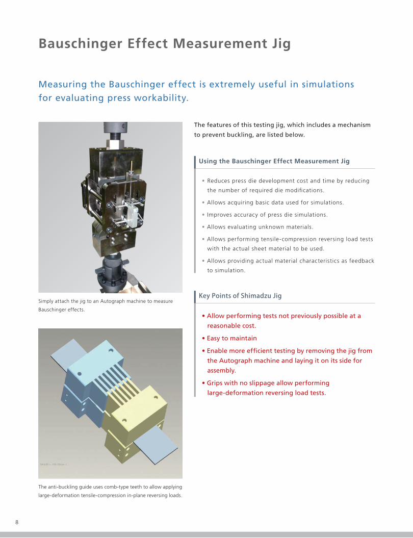
Measuring the Bauschinger effect is extremely useful in simulations for evaluating press workability.
Using the Bauschinger Effect Measurement Jig
Key Points of Shimadzu Jig
• Allow performing tests not previously possible at a
reasonable cost.
• Easy to maintain
• Enable more ef�cient testing by removing the jig from
the Autograph machine and laying it on its side for
assembly.
• Grips with no slippage allow performing
large-deformation reversing load tests.
AG-100kN
100 kN tensile and 100 kN compression
Manual hydraulic pump
Max. 40 kN
Strain gauge type
50 mm
+50 % / -10 %
JIS B 7741 Class 1
200 mm total length by 40 mm wide
60 mm long and 25 mm wide area with parallel sides
1 mm to 3 mm thick
200 mm total length by 45 mm wide
60 mm long and 35 mm wide area with parallel sides
1 mm to 3 mm thick
Room temperature
Hydraulic Source
Straightening Pressure
Type
Gauge Length
Measurement Range
Measurement Precision
JIS No. 5
JIS Special No. 5
(wider specimen width)
Applicable Model
Loading Capacity
Anti-Buckling Unit
Elongation Measurement Device
Applicable Test Specimens
Operating Temperature Range
Speci�cations
The anti-buckling guide uses comb-type teeth to allow applying
large-deformation tensile-compression in-plane reversing loads.
Simply attach the jig to an Autograph machine to measure
Bauschinger effects.
• Reduces press die development cost and time by reducing
the number of required die modi�cations.
• Allows acquiring basic data used for simulations.
• Improves accuracy of press die simulations.
• Allows evaluating unknown materials.
• Allows performing tensile-compression reversing load tests
with the actual sheet material to be used.
• Allows providing actual material characteristics as feedback
to simulation.
The features of this testing jig, which includes a mechanism
to prevent buckling, are listed below.
Tru
e St
ress
(N
/mm
2)
Extensometer 1 (true strain) (%)
1000
800
600
400
200
-200
-400
-600
-800
-1000
0
-6.5 -6 -5 -4 -3 -2 -1 0 1 2 3 4 5 6 6.5

98
Bauschinger Effect Measurement Jig
Measuring the Bauschinger effect is extremely useful in simulations for evaluating press workability.
Using the Bauschinger Effect Measurement Jig
Key Points of Shimadzu Jig
• Allow performing tests not previously possible at a
reasonable cost.
• Easy to maintain
• Enable more ef�cient testing by removing the jig from
the Autograph machine and laying it on its side for
assembly.
• Grips with no slippage allow performing
large-deformation reversing load tests.
AG-100kN
100 kN tensile and 100 kN compression
Manual hydraulic pump
Max. 40 kN
Strain gauge type
50 mm
+50 % / -10 %
JIS B 7741 Class 1
200 mm total length by 40 mm wide
60 mm long and 25 mm wide area with parallel sides
1 mm to 3 mm thick
200 mm total length by 45 mm wide
60 mm long and 35 mm wide area with parallel sides
1 mm to 3 mm thick
Room temperature
Hydraulic Source
Straightening Pressure
Type
Gauge Length
Measurement Range
Measurement Precision
JIS No. 5
JIS Special No. 5
(wider specimen width)
Applicable Model
Loading Capacity
Anti-Buckling Unit
Elongation Measurement Device
Applicable Test Specimens
Operating Temperature Range
Speci�cations
The anti-buckling guide uses comb-type teeth to allow applying
large-deformation tensile-compression in-plane reversing loads.
Simply attach the jig to an Autograph machine to measure
Bauschinger effects.
• Reduces press die development cost and time by reducing
the number of required die modi�cations.
• Allows acquiring basic data used for simulations.
• Improves accuracy of press die simulations.
• Allows evaluating unknown materials.
• Allows performing tensile-compression reversing load tests
with the actual sheet material to be used.
• Allows providing actual material characteristics as feedback
to simulation.
The features of this testing jig, which includes a mechanism
to prevent buckling, are listed below.
Tru
e St
ress
(N
/mm
2)
Extensometer 1 (true strain) (%)
1000
800
600
400
200
-200
-400
-600
-800
-1000
0
-6.5 -6 -5 -4 -3 -2 -1 0 1 2 3 4 5 6 6.5

1110
Biaxial Tensile Test Jig
Includes various convenient features.1
Compliant with ISO 16842 test standard2
• Enables axial tensile testing by simply setting up the jig on the Autograph machine.
• A detachable arm allows changing the tensile ratio to 1:1, 1:1.5, or 1:2.
• Machine can be acquired for a reasonable cost. • Lack of hydraulics provides easy maintenance.
• Other tests can be performed on the same machine.
• The pre-tension adjustment screw allows applying an initial load with good reproducibility and simpli�es the setup process.
• Tensile, compression, and bending jigs can be attached with the biaxial tensile test jig installed.
B=30
B<L<2B
B/2<C<B
Ws<0.05mm
1200
1000
800
600
400
200
0
0 200 400 600 800 1000 1200
δγ N
/mm
2
δχ N/mm2
0.002
0.005
0.01
0.02
ε ρ0
20 kN50 kN
Class 1
1/1 to 1/50
Compliant with ISO 16842 Metallic materials - Sheet and strip -
Biaxial tensile testing method using a cruciform test piece
30 mm wide cruciform with 150, 180, or 210 mm sides (180 and 210 mm sizes are optional)
0.6 to 3.2 mm
1:1, 1:1.5, or 1:2
7.5 mm
30 kg upper and 160 kg lower
Max. Test Force
Test Force Precision
Test Force Measurement Range
Applicable Test Standards
Applicable Specimen Shapes
Applicable Specimen Thicknesses
Biaxial Tensile Stress Ratio
Stroke (pulsating)
Weight
Biaxial Tensile Test Jig Speci�cations
For AG-250/300kN For AG-100kN
Arm
Clevis area
Adjustmentscrew
Pre-tension can be adjusted using the adjustment screw.
Benefits compared to a dedicated machine3
Biaxial tensile testing helps improve the accuracy of press forming simulations by more closely approximating
actual loading conditions. Previously, there was no uni�ed standard and no commonly used evaluation method.
However, with the release of ISO 16842, biaxial tensile testing methods have now been standardized globally.
Standardization has provided reliable testing methods by taking into consideration the use of sample shapes that
are less likely to cause interference with other axes and by specifying the location to af�x strain gauges so that
they reliably measure biaxial strain. The testing jig is compliant with ISO 16842 standards, enabling tests to be
performed easily by simply attaching the jig to the Autograph machine.
The following example shows results from using different tensile stress ratios to test high tensile steel.
It shows how results change as the tensile stress ratio changes.
During Measurement 0:1 Tensile Ratio (uniaxial)
S-S Curve for High Tensile Steel at 0:1(normal TP)
1:2 Tensile Ratio
1:1.5 Tensile Ratio 1:1 Tensile Ratio
Note: The drop in test force at the end of the X-axis for 1:1 is due to sample failure.
00
200
400
600
800
1000
1200
5000 10000 15000 20000 25000 30000 35000
Stre
ss (N
/mm
2 )
Strain (μs)
S-S Curve for High Tensile Steel at 1:2(normal TP)
00
200
400
600
800
1000
1200
5000 10000 15000 20000
Stre
ss (N
/mm
2 )
Strain (μs)
S-S Curve for High Tensile Steel at 1:1.5(normal TP)
00
200
100
300
400
500
600
700
5000 10000 15000 20000
Stre
ss (N
/mm
2 )
Strain (μs)
S-S Curve for High Tensile Steel at 1:1(normal TP)
00
200
100
300
400
500
600
700
5000 10000 15000 20000
Stre
ss (N
/mm
2 )
Strain (μs)
Y Stress Y Stress
X Stress
Y Stress
X Stress
Y Stress
X Stress

1110
Biaxial Tensile Test Jig
Includes various convenient features.1
Compliant with ISO 16842 test standard2
• Enables axial tensile testing by simply setting up the jig on the Autograph machine.
• A detachable arm allows changing the tensile ratio to 1:1, 1:1.5, or 1:2.
• Machine can be acquired for a reasonable cost. • Lack of hydraulics provides easy maintenance.
• Other tests can be performed on the same machine.
• The pre-tension adjustment screw allows applying an initial load with good reproducibility and simpli�es the setup process.
• Tensile, compression, and bending jigs can be attached with the biaxial tensile test jig installed.
B=30
B<L<2B
B/2<C<B
Ws<0.05mm
1200
1000
800
600
400
200
0
0 200 400 600 800 1000 1200
δγ N
/mm
2
δχ N/mm2
0.002
0.005
0.01
0.02
ε ρ0
20 kN50 kN
Class 1
1/1 to 1/50
Compliant with ISO 16842 Metallic materials - Sheet and strip -
Biaxial tensile testing method using a cruciform test piece
30 mm wide cruciform with 150, 180, or 210 mm sides (180 and 210 mm sizes are optional)
0.6 to 3.2 mm
1:1, 1:1.5, or 1:2
7.5 mm
30 kg upper and 160 kg lower
Max. Test Force
Test Force Precision
Test Force Measurement Range
Applicable Test Standards
Applicable Specimen Shapes
Applicable Specimen Thicknesses
Biaxial Tensile Stress Ratio
Stroke (pulsating)
Weight
Biaxial Tensile Test Jig Speci�cations
For AG-250/300kN For AG-100kN
Arm
Clevis area
Adjustmentscrew
Pre-tension can be adjusted using the adjustment screw.
Benefits compared to a dedicated machine3
Biaxial tensile testing helps improve the accuracy of press forming simulations by more closely approximating
actual loading conditions. Previously, there was no uni�ed standard and no commonly used evaluation method.
However, with the release of ISO 16842, biaxial tensile testing methods have now been standardized globally.
Standardization has provided reliable testing methods by taking into consideration the use of sample shapes that
are less likely to cause interference with other axes and by specifying the location to af�x strain gauges so that
they reliably measure biaxial strain. The testing jig is compliant with ISO 16842 standards, enabling tests to be
performed easily by simply attaching the jig to the Autograph machine.
The following example shows results from using different tensile stress ratios to test high tensile steel.
It shows how results change as the tensile stress ratio changes.
During Measurement 0:1 Tensile Ratio (uniaxial)
S-S Curve for High Tensile Steel at 0:1(normal TP)
1:2 Tensile Ratio
1:1.5 Tensile Ratio 1:1 Tensile Ratio
Note: The drop in test force at the end of the X-axis for 1:1 is due to sample failure.
00
200
400
600
800
1000
1200
5000 10000 15000 20000 25000 30000 35000
Stre
ss (N
/mm
2 )
Strain (μs)
S-S Curve for High Tensile Steel at 1:2(normal TP)
00
200
400
600
800
1000
1200
5000 10000 15000 20000
Stre
ss (N
/mm
2 )
Strain (μs)
S-S Curve for High Tensile Steel at 1:1.5(normal TP)
00
200
100
300
400
500
600
700
5000 10000 15000 20000
Stre
ss (N
/mm
2 )
Strain (μs)
S-S Curve for High Tensile Steel at 1:1(normal TP)
00
200
100
300
400
500
600
700
5000 10000 15000 20000
Stre
ss (N
/mm
2 )Strain (μs)
Y Stress Y Stress
X Stress
Y Stress
X Stress
Y Stress
X Stress

© Shimadzu Corporation, 2015
Printed in Japan 3655-01511-15AIK
Evaluation of Press Work on Sheet M
etal
Evaluation of Press Work on Sheet Metal— Obtaining Accurate Design Data Usable for Simulation —
C224-E061
Evaluation of Work HardeningEvaluation of Drawability
Plane Deep Drawability Test
Evaluation of Die Slipperiness
Drawbead Testing System
Autograph Precision Universal Testing Machine
AG-X plus Series
Material Testing Operation Software
TRAPEZIUM XAutomatic Extensometer
SIE-560/560S
Related Testing and Evaluation Instruments
HMV-GMicro Vickers Hardness Tester