evaluation of oxygen-enriched air combustion...
TRANSCRIPT

Int. J. of Thermal & Environmental EngineeringVolume 5, No. 2 (2013) 113-121
* Corresponding author. Tel.: +97128109181E-mail: [email protected]© 2013 International Association for Sharing Knowledge and SustainabilityDOI: 10.5383/ijtee.05.02.003
113
Evaluation of Oxygen-Enriched Air Combustion Process Integrated withCO2 Post-Combustion Capture
Adewale Adeosun, Aravind Muthiah, Mohammad R. M. Abu-Zahra*
Separation Technology Laboratory, Masdar Institute of Science and Technology, P.O. Box 54224, Abu Dhabi, United Arab Emirates
AbstractA novel concept combining membrane-based technology for air enrichment combustion process integrated with solvent-based post-combustion capture is evaluated using Aspen Plus® process simulation tool. The aim of this integratedconcept is to reduce the amount of Nitrogen used in the combustion process and as a result increase the CO2
concentration in the flue gas. The effects of the increased CO2 concentration on liquid-to-gas molar flow ratio, solventflow rate, reboiler duty and washing water requirement are evaluated. Based on the cost analysis for the air separationunit and the CO2 capture solvent flow rate and washing water requirement, the optimum enrichment level of air wasfound to be 35% O2. However, in term of CO2 mole concentration in the flue gas and liquid-gas molar ratio in theabsorption process, 40% enrichment shows highest value of 28.22% and 7.15, respectively. No significant benefit isobserved in terms of reboiler duty as expected due to the fixed amount of CO2 captured and the limited increase in thesolvent rich loading. On the other hand, the flue gas flow rate was reduced dramatically at higher CO2 concentration,which will result in a smaller absorption tower and consequently a lower capital investment. In addition, with improvedmembrane technology that can work at lower air inlet pressure and with higher oxygen permeability and selectivity, thetarget energy reduction is achievable. These results encourage a full scale economic evaluation of the novel process ofcombining enriched air combustion and AMP-solvent based post-combustion capture to be conducted in order to weighenrichment costs to absorber size reduction economic benefits.
Keywords: Carbon Capture, Post Combustion, Membrane, Coal power plant, Simulation
1. Introduction
The impact of climate change is becoming increasinglyevident, posing significant challenge, both in the political andscientific arenas. The emission of greenhouse gases has beenreported to be the main cause of global warming [1,2,3]. Tomitigate impacts, carbon dioxide capture and storage (CCS) isexpected to play significant role [4]. Since power plants,transportation, cement, metallurgical industries among othersconstitute the largest source of greenhouse gas emission [5], itbecomes vivid why technology research is focused oncapturing CO2 emissions from stationary sources.
Three key technologies are currently available for CCS, anoverview of which is described in Figure 1 [6]. Post-combustion capture technology is focused on separating carbondioxide from the flue gas using conventional chemicalabsorption or other novel options such as adsorption. Pre-
combustion capture technology is centered on fuelgasification, syngas shifting and extracting hydrogen from fuelthrough gasification. Oxyfuel combustion technology involvesthe combustion of fuel in pure oxygen, leading to high purityCO2 effluent. However, techno-economic evaluations of thevarious technologies indicate that there is yet to be found thewinning technology [7,8]. The winning technology will be onewhich meets the roadmap targets in terms of operating energypenalty, low cost of CO2 avoided and a reduction on capitalinvestment [9].
Novel process involving membrane-based air enrichment,integrated with post-combustion capture technology isattracting attention [10, 11]. In fact, energy penalty reductionby 35% is reported to be achievable [12]. In this work, AspenPlus is used to evaluate air enrichment, fuel combustion usingthe enriched air and the post-combustion capture with a view toevaluating enrichment impacts on flue gas composition, liquid-to-gas ratio, washing water requirement and reboiler duty. Thenovel evaluated concept is illustrated in the block diagramshown in Figure 2.

Adeosun et al. / Int. J. of Thermal & Environmental Engineering, 5 (2013) 113-121
114
Fig.1. Schematic representation of the different capture systems [6]
Fig.2. Block diagram of enriched air combustion with AMP-solvent based CO2 capture
2. Background
Global dependence on fossil fuel is expected to increase untilthe middle of the century, especially from the emergingeconomies in Asia and Africa. New coal- and gas-fired powerplants will be built in order to meet the growing demand forelectricity and other industrial needs. To ensure that 50% CO2
reduction target is met, key technologies including CCS,nuclear energy, improved energy/process efficiency, fuelswitching and renewable energy utilization are promoted byInternational Energy Agency [4]. For CCS, Post-combustiontechnology is the near term option for industrial deploymentdue to its retrofitability to existing power plants, suitability tolow CO2 partial pressure systems and process maturity, as
applied to gas sweetening [13]. However, large scaleimplementation for CO2 capture is plagued with high energypenalty and the capital intensive nature of the capture plant forthe monoethanolamine (MEA)-based chemical absorption.This leads to increased power generation cost.
Efforts have been made to improve the process foreconomic viability. For example, major energy savings arereported through parametric optimizations involving leansolvent loading, amine solvent concentration, stripper operatingpressure, capture ratio, process temperature and pressure[9,14]. However, MEA-based PCC has been identified to havelow absorption capacity, low cyclic capacity, high degradationrate, high equipment corrosion rate and high regeneration

Adeosun et al. / Int. J. of Thermal & Environmental Engineering, 5 (2013) 113-121
115
energy requirement [15]. This has necessitated research intoother classes of amines including sterically-hindered-amines(e.g. AMP), secondary, tertiary amines and heterocyclic aminesincluding piperazine.
In addition, smart process design, novel integration andadvanced solvents are to be investigated to make CO2 captureeconomically feasible for industrial deployment [9]. Otherefforts consider the option of increasing the CO2 concentrationin the flue gas stream either by recycling the flue gas with freshair over the boiler or by utilizing the concept of air enrichment[16,17,25]. Both options are expected to be beneficial to theoverall capture scenario due to expected reduction in flue gasflow rate. Thus, smaller absorber/desorber columns will berequired under these conditions. The capital investment cost,cost of CO2 avoided and the cost of electricity will be reduced.Based on these aforementioned benefits, this work evaluatesmembrane-based air enrichment integrated with post-combustion capture is applied to a coal-fired power plant usingAspen Plus simulations.
3. Process and Simulation Description
3.1. Air EnrichmentCryogenic separation has been the choice for high purityoxygen production for large scale production among thevarious available technologies as depicted in Table 1 [18].However, the energy penalty associated with the subzerooperations with the attending high capital investment in termsof equipment size and waste energy has led to findingalternatives. Modern membrane engineering has been seen asone of the future technologies to meet the roadmap targets forhigh CO2 flue gas concentration; hence the need for enrichedair combustion [19, 20].
Table 1. Oxygen production technology alternatives[18].
The choice of membrane in this work is based on permeability,selectivity, material structure and thickness and operatingtemperature. Recent work of Robeson [21] showed thatmembranes made of polymers of intrinsic microporosity (PIM)have better material properties and better trade-offs betweenoxygen permeability and oxygen-nitrogen selectivity. Theproperties needed for the simulation is presented in Table 2.
As a pressure-driven process, compressor with isentropicefficiency of 85% and mechanical efficiency of 95% wasselected for the simulation with outlet pressure values of 3, 5,
10, 15, 20 and 30 bar for the parametric studies. For each ofthese pressure values, the corresponding membrane area isdetermined using the mathematical relation in Equation 1 [12]and the compressor cost is determined from the electricalenergy consumption as obtained from simulations.
Table 2. Membrane Modeling Fixed Parameters
Parameter Value Unit Reference
Oxygen Permeability 100 Barrer [23]
Thickness of membrane 2.00E-06 m [24]
Pressure on permeateside
1.013 bar
Cost of membrane 45 $/m2
(1)
The optimum pressure is determined from total capital cost plotagainst the pressure. The capital cost accounts to the membraneand compression costs only. Separator unit was chosen tomodel the membrane in the simulation and the processconsiders 25%, 30%, 35% and 40% air enrichment subjected tothe limitation for polymeric membranes as indicated in Table 1.Economic evaluation is restricted to the enrichment section.
3.2. Power Plant Description
The conventional power plants, novel and advancecombustion processes and their related gaseous emissions arewell established technology as discussed intensively in openliterature [26, 27, 28, 29]. Figure 3 shows the power plantsimulation with the enrichment section. The power plantsimulation involves coal crushing, enriched air combustion,steam turbine electricity production, flue gas cooling andrecirculation section. Due to the pressure gradient and thehigher selectivity and permeability of the chosen membrane,enriched air is produced and pumped into combustion furnace.Assumptions for power plant simulations include thefollowing: Fuel rate of 3kg/s is considered in all cases.
Lean fuel combustion at 5% excess oxygen in the hotgas from the furnace. This is essentially set to justifycomplete combustion of coal assumption.
Since increased oxygen relative to nitrogencomposition is expected to lead to higher combustiontemperature, flue gas is recirculated with fresh enrichedair to keep the boiler temperature at 1400°C. Thistemperature is well below the fuel adiabatic flametemperature and therefore hinders the thermal NOxformation which is promoted beyond1800°C [22].
Coal typically delivered at the power plant as non-pulverized and characterized with different sizes that can reachseveral centimeters. Therefore, crushing of the coal isimportant to increase the specific surface area per unit volume.Also, complete combustion of the fuel can be achieved whenthe particle size distribution is within the range of 180 to 360microns. Multistage crushing model is used; with multiplescreens to sieve the coal particles to the appropriate size. Toensure a reduction in the power consumption by the crushingprocess as a result of solid transport, the coal particles are
Process StatusByproductCapability
Purity(vol%)
Cryogenic Mature Excellent 99+
Adsorption Semi-mature Poor 95
Polymericmembrane Semi-mature Poor ≈40
Chemical Developing Poor 99+
CeramicMembrane Developing Poor 99+

Adeosun et al. / Int. J. of Thermal & Environmental Engineering, 5 (2013) 113-121
116
mixed with water. This leads to addition in the coal particlemoisture content up to 15wt%.
In Aspen Plus simulation, the final coal particles wereseparated from the conveying water stream through a SEP2unit. The coal properties were established on chemical speciesassociated with both conventional and non-conventionalfeedstock specifications. For the physical property, Peng-Robinson with Mathias modification was used to model gasphase behavior. Elemental composition reactions are used torepresent coal combustion summary of the coal proximate andultimate properties, the coal fuel feed composition is given inTable 3. At this combustion temperature and particle size, theburner is modeled with RGibbs reactor, achieving equilibriumachieved through the Gibbs free energy minimization. Aftercombustion, the particulate matters are separated from the fluegas using SSplit model as an electrostatic precipitator. The hotgas stream is then used to produce superheated steam at 500°Cand 35atm pressure, modeled using two heater unit operations.This is subsequently used to be expanded in a steam turbinewhich is coupled with electric generator for electricityproduction. Before the flue gas is channeled to the stack, it issubjected to desulphurization and it is modeled using separatorand cooler units.
Table 3. Coal Feed Composition [30]
Component weight %
Moisture 9.535
Fixed carbon 50.909
Volatile matter 39.452
Ash 9.639
3.3. Post-Combustion Capture Description
Though, AMP has lower reaction kinetics than MEA, it isappropriate for enriched air post-combustion capturesimulation. This is because the potential higher cyclic loadingof AMP that can be harnessed, compared to MEA at higherCO2 partial pressure [25]. This will lead to lower solvent rateand higher liquid-to-gas ratio, thus smaller absorber size. Areduction in the condenser water rate is expected due to AMPlow vapour pressure. This can ultimately lead to elimination ofwashing section, and reducing further the capital expenditure.
The process flow sheet diagram is presented in Figure 4.The flue gas is set to 1.2 bar pressure and 50°C temperature.Each of the obtained flue gas streams is simulated for thescrubbing using Radfrac unit as the absorber, with 4 stages anda pressure drop of 10kPa. The rich solvent from the bottoms ofthe absorber is pumped to 2.3 bar pressure to enhance the CO2
desorption in the stripper. The pressurized rich solvent streampasses through a cross heat exchanger where it receives heatfrom the stripper bottom outlet stream. This cross heatexchanger is an important heat integration option to reduce theamount of thermal energy required for the feed stream enteringthe stripper for regeneration. The stripper is modeled usingRadfrac with 6 stages, 1.8 bar column bottom pressure and30kPa column pressure drop.
The constraints used for the simulation is 90% CO2
recovery by mole and less than 97% CO2 mass fraction in theCO2 stream from the top of the stripper. The simulation is donewith a heat exchanger design given by the difference in the hotstream outlet temperature and the cold stream outlettemperature. In this case, 5°C is chosen.
HIERARCHY
CRUSHING
CUNIT
BURNER2
BOILER-A
GRATE
SULREMOV
AIRSEP
COMP
SPLITTER
BOILE-B
PUMP
TURBINE
COOLER
CCOAL
IN
BURNER1
HOT-PRODHOTGAS
COOLPROD
QBOIL
ASH
SULPH
CLEANGAS
FEEDCOAL
ENRAIR
COMP-AIR
NITROGEN
AIR WORK1W
FG-PCC
FG-RECYC
WATER ST EAM
WTR
COND
EPOWERW
FG-PCC2
Fig. 3. Coal-fired power plant with air enrichment section simulation process flow sheet

Adeosun et al. / Int. J. of Thermal & Environmental Engineering, 5 (2013) 113-121
117
ABSORBER
PUMP
HX
DESORBER
COND
COOLER
WASHTRAY
FG-ABS
RICH-AMP
V-GAS
LEAN-AMP
R-AMP-H
R-AMP-S
L-AMP-X
L-AMP-C
VAP
LIQ
CO2
WASHSOL
VENTGAS
WATER
Fig. 4. Post-combustion CO2 capture simulation process flow sheet.
4. Results and Discussion
4.1. Air Enrichment Result
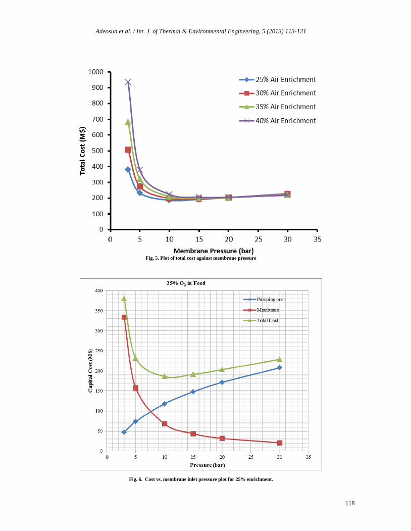
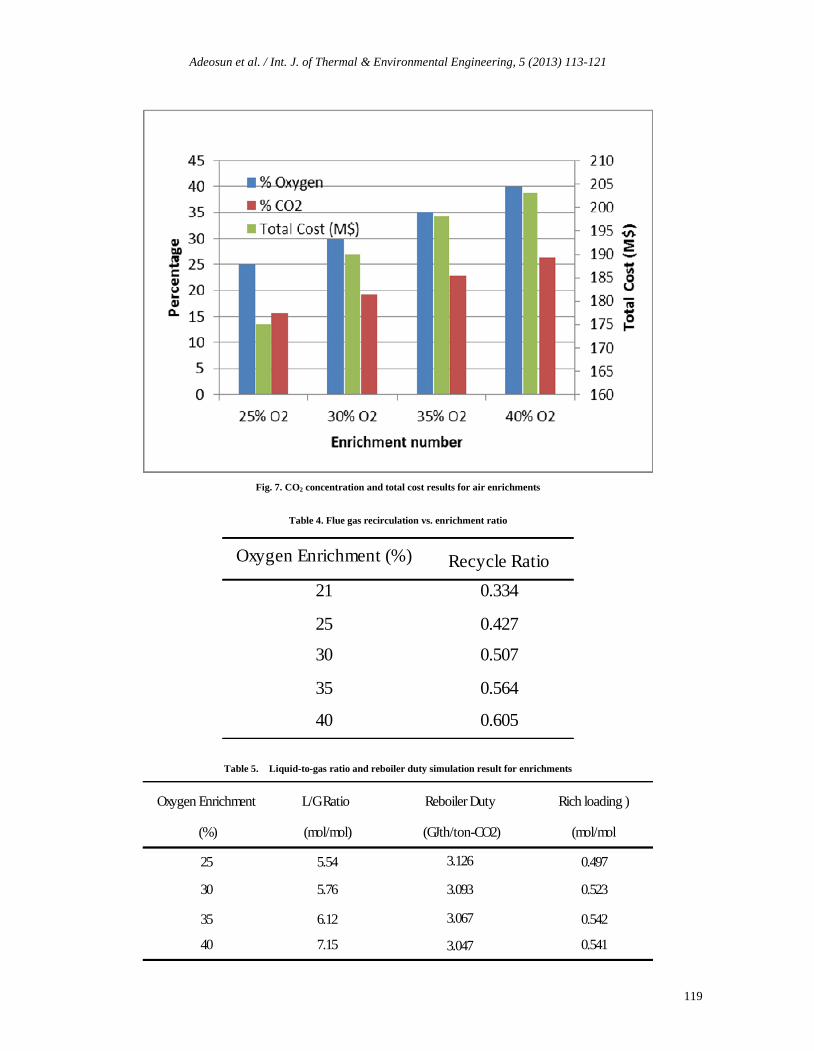
Figure 5 shows the total cost against pressure for four oxygenenrichments levels. It is observed that the cost is higher at lowpressure and as the enrichment percentage increases. However,at higher compression, the cost flattens out for pressure above19 bars. The observed result implies that increasing the air inletcompression cost is counterbalanced by reduction in membranecost of the same order of magnitude as a result of a smallermembrane area requirement. Figure 6 elaborates on one of theoxygen enrichment as an example of 25% enrichment. Theoptimum pressure in this specific case is found to be 11.5 bar,giving a total membrane and compression cost of US$180million. Figure 7 shows a plot of optimum pressure againsttotal cost and the enrichment. As expected, the minimum costat optimum membrane inlet pressure increases with increasingenrichment ratio. At 40% air enrichment, carbon dioxide molepercent rises to 28.22% with optimum pressure of 17.5bar. ThisCO2 concentration is about twice the observed concentrationfor conventional air combustion process.
4.2. Combustion Result
The combustion process is simulated with flue gas recirculationin other to avoid increased NOx concentrations due to higheroxygen concentrations from enrichment. Flue gas is recycled toachieve 1400°C hot gas temperature from the furnace. Table 5gives the recycle ratio required to obtain the temperature setvalue. The result shows that significant amount of the flue gasmust be recycled. In the case of 40% enrichment, above 60% isrecycled, about twice the requirement in the case of conventioncombustion process. This reiterates the significant importanceof nitrogen as a diluent in combustion process. With this airenriched concept, more detailed study should be carried out to
evaluate the effect on the combustion process efficiency,operation and emissions.
4.3. Post-Combustion Capture Result
Table 4 shows liquid-to-gas ratios and reboiler duties whileTable 6 presents the solvent flow rates and washing water flowrate requirements for various enrichments. In both tables,values are compared with AMP-based post-combustion capturevalues using conventional air of 21% oxygen by mole. Theliquid-to-gas flow rates increase with increasing airenrichment. This is expected due to the reduction in the gasflow rate from air enrichment. With the same amount of fuelused in combustion process and same amount of CO2 to becaptured, the liquid flow rate requirement is marginal indifference for various enrichments. In terms of the reboilerduty, there is marginal decrease as the enrichment proportionincreases, which directly connected with the increase in thesolvent rich loading. With the air enrichment (N2 decrease), theCO2 concentration increases in the flue gas, the composition ofthe rich solvent to the stripper is also increased. This is thecritical factor that determines the reboiler duty. From table 5, itis observed that 35% air enrichment has the lowest solventflow rate of 15.36 L/kg-CO2 and lowest washing waterrequirement of 0.02 L/kg-CO2. Essentially, 40% air enrichmentis expected to have smallest absorber size reduction due to itslower liquid-gas ratio. When compared to the reference case ofconventional air combustion with AMP scrubbing with 4.38liquid-to-gas ratio, air enrichment of 40%. shows 44% decreasein flue gas flow rate, leading to 63% increase in liquid-to-gasratio. Since absorber typically represents 50% of purchasedequipment cost and gas path equipment constitutes 75% oftotal capture equipment cost [9], a significant reduction inabsorber size is expected at constant liquid flow. 25%, 30%and 35% enrichments show 14.8%, 27% and 37% reduction influe gas flow rates respectively, indicating expected benefits interms of reduced equipment cost from smaller absorber size.
Adeosun et al. / Int. J. of Thermal & Environmental Engineering, 5 (2013) 113-121
118
Fig. 5. Plot of total cost against membrane pressure
Fig. 6. Cost vs. membrane inlet pressure plot for 25% enrichment.
Adeosun et al. / Int. J. of Thermal & Environmental Engineering, 5 (2013) 113-121
119
Fig. 7. CO2 concentration and total cost results for air enrichments
Table 4. Flue gas recirculation vs. enrichment ratio
Oxygen Enrichment (%) Recycle Ratio
21 0.334
25 0.427
30 0.507
35 0.564
40 0.605
Table 5. Liquid-to-gas ratio and reboiler duty simulation result for enrichments
Oxygen Enrichment L/G Ratio Reboiler Duty Rich loading )
(%) (mol/mol) (GJth/ton-CO2) (mol/mol
25 5.54 3.126 0.497
30 5.76 3.093 0.523
35 6.12 3.067 0.542
40 7.15 3.047 0.541
Adeosun et al. / Int. J. of Thermal & Environmental Engineering, 5 (2013) 113-121
120
Table 6. Solvent flow rate and washing water requirement
OxygenEnrichment (%)
Solvent Flowrate(L/kg-CO2)
Washing Water rate(L/kg-CO2)
21 16.93 0.16
25 17.38 0.06
30 16.10 0.05
35 15.36 0.02
40 15.50 0.05
5. Conclusion
Air enrichment combustion process integrated with CO2 post-combustion capture in coal-fired power plant was evaluated.Membrane made of polymers of intrinsic microporosity is usedfor the enrichment due to its permeability and selectivity foroxygen. The optimum pressures for 25%, 30%, 35% and 40%enrichment are determined using the minimum total cost ofcompression and membrane. The combustion process isdesigned to produce hot gas at 1400°C, using flue gasrecirculation and 5% excess oxygen design specifications. Theflue gas CO2 composition increased to 28% on molar basis for40% oxygen enrichment. 35% oxygen enrichment showslowest solvent flow rate and washing water requirement.
The result shows that the main benefit of the enrichment onpost-combustion capture is the reduction of the flue gas flowrate, which clearly results in a reduction in the absorber size,introspectively leading to reduced capital cost. The increase inthe solvent rich loading and the decrease in the solventregeneration energy were found to be very marginal. Withadvances in membrane technology, greater reduction in costcan be expected in the enrichment section. As more advancedsolvents are developed, enriched air combustion with post-combustion capture will lead to more significant costreduction.
As a future research work, a full scale economic evaluation ofthis novel process combining enriched air combustion andpost-combustion capture will be conducted to weigh theenrichment cost to absorber size reduction economic benefits.
Nomenclature
Qp air volumetric flow rate
ya oxygen outlet mole fraction.
Am membrane area.
PA oxygen permeability.
ph inlet air pressure
pl outlet air pressure
xA oxygen inlet mole fraction.
L membrane thickness
References
[1] R. Steeneveldt, B. Berger, T.A. Torp, CO2 Capture andStorage: Closing the Knowing–Doing Gap, ChemicalEngineering Research and Design, Vol. 84, Issue 9,September, 2006, pages 739-763.http://dx.doi.org/10.1205/cherd05049
[2] D.J. Wuebbles, A.K. Jain. Concerns about climate changeand the role of fossil fuel use, Fuel ProcessingTechnology, Volume 71, Issues 1-3, June 2001, Pages 99-119.
[3] IPCC. Climate change 2001: impacts, adaptation andvulnerability. Contribution of Working Group II to theThird Assessment Report of the Intergovernmental Panelon Climate Change. Cambridge: Cambridge UniversityPress; 2001.)Haik, Y: Engineering Design Process. PacificGrove: Brooks/Cole, 2003.
[4] International Energy Agency (IEA). “Energy TechnologyPerspectives, 2010: Scenarios and Strategies to 2050”.http://www.iea.org/techno/etp/index.asp.
[5] IPCC, 2007. Climate Change, 2007: Synthesis Report.Contribution of working groups I, II, III to the FourthAssessment Report of the Intergovernmental Panel onClimate Change. Geneva, Switzerland.
[6] IPCC, 2005. Carbon Dioxide Capture and Storage.Cambridge University Press.
[7] A.A. Olajire. CO2 capture and separation technologies forend-of-pipe applications – a review. Energy 35, 2010,2610–2628. http://dx.doi.org/10.1016/j.energy.2010.02.030
[8] P. Deschamps, P.A. Pilavachi, Research and developmentactions to reduce CO2 emissions within the EuropeanUnion, Oil Gas Sci. Technol. 59 (3) (2004) 323–330.http://dx.doi.org/10.2516/ogst:2004023
[9] M. Abu-Zahra, et al., CO2 Capture from Power Plants PartI: A Parametric Study of the Technical Performance Basedon Monoethanolamine. International Journal ofGreenhouse gas Control, 1 (2007) 37-46.http://dx.doi.org/10.1016/S1750-5836(06)00007-7
[10] E. Favre, Carbon dioxide recovery from post combustionprocesses: can gas permeation membranes compete withabsorption?, J Membr. Sci. 294 (2007) 50–59.http://dx.doi.org/10.1016/j.memsci.2007.02.007
[11] M.T. Ho, G.W. Allinson, D.E. Wiley, Reducing the cost ofCO2 capture, from flue gases using membrane technology,Ind. Eng. Chem. Res. 47 (2008) 1562–1568.http://dx.doi.org/10.1021/ie070831e
[12] B. Belaissaoui, Y. Le Moullec, D. Willson, E. Favre.Hybrid membrane cryogenic process for post-combustionCO2 capture, J. Membr. Sci. 415–416 (2012) 424–434.http://dx.doi.org/10.1016/j.memsci.2012.05.029
[13] P. Feron. Progress in post-combustion CO2 capture.Presentation for the international symposium, reduction ofemissions and geological storage of CO2.
[14] C. Alie, L. Croiset, E. Douglas. Simulation of CO2 captureusing MEA scrubbing: a flow sheet decompositionmethod. Energy Convers. Mgm. 46, 475-487.
[15] A. Kohl, R. Nielsen. Gas purification. 5th Edition, GulfPublishing Company. 1997.

Adeosun et al. / Int. J. of Thermal & Environmental Engineering, 5 (2013) 113-121
121
[16] A. Hussain, M.B. Hägg, A feasibility study of CO2 capturefrom flue gas by a facilitated transport membrane, J.Membr. Sci. 359 (1–2) (2010) 140–148.http://dx.doi.org/10.1016/j.memsci.2009.11.035
[17] P. Descchamps, P.A. Pilavachi, Research and developmentactions to reduce CO2 emissions within the EuropeanUnion, Oil Gas Sci. Technol. 59 (3) (2004) 323–330.http://dx.doi.org/10.2516/ogst:2004023
[18] A.R. Smith, J. Klosek. A review of air separationtechnologies and their integration with energy conversionprocesses. Fuel Processing Technology 2001;70:115–34.http://dx.doi.org/10.1016/S0378-3820(01)00131-X
[19] N. Bounaceur, N. Lape, D. Roizard, C. Vallières, E. Favre,Membrane processes for post-combustion carbon dioxidecapture: a parametric study, Energy 31 (2006) 2556–2570.http://dx.doi.org/10.1016/j.energy.2005.10.038
[20] J.K. Jeon, S.K. Ihm, Y.K. Park, J.S. Kim, J.I. Dong, S.Kim, J.M. Kim, S. Kim, K.S. Yoo. Membrane/PSA hybridprocess for carbon dioxide recovery at low concentration,Stud. Surf. Sci. Catal. 153 (2004) 543–546.http://dx.doi.org/10.1016/S0167-2991(04)80311-2
[21] J.M. Robeson. Upper Bound Revisited. J. Membr Sci. 320(2008) 390–400.http://dx.doi.org/10.1016/j.memsci.2008.04.030
[22] S.R. Turns. An introduction to combustion: concepts andapplications. 2nd Edition. McGraw Hill Series. 2000.
[23] E. Drioli et al. Membrane Gas Separation: A Review/StateOf The Art. Ind. Eng. Chem. Res. 2009, 48, 4638-4663.http://dx.doi.org/10.1021/ie8019032
[24] M.B.Hägg, A. Lindbråthen, CO2 Capture from natural gasfired power plants by using membrane technology. Ind. &Eng. Chem. Res. 2005. 44(20): p. 7668-7675.http://dx.doi.org/10.1021/ie050174v
[25] M.R.M Abu-Zahra, P. Feron, P. Jansens, E. Goetheer, Newprocess concepts for CO2 post-combustion capture processintegrated with co-production of hydrogen. Int journal ofhydrogen energy 34 (9) (2009), 3992-4004.http://dx.doi.org/10.1016/j.ijhydene.2009.02.056
[26] I. Janajreh, S. Raza, A. Valmundsson, Plasma gasificationprocess: modelling, simulation and comparison withconventional air gasification. Energy conversion andmanagement, 65 (2013) 801-809.http://dx.doi.org/10.1016/j.enconman.2012.03.010
[27] S. Syed, R. Qudaih, I. Talab, I. Janajreh, Kinetics ofpyrolysis and combustion of oil shale sample fromthermogravimetric data. Fuel, 90 (2011) 1631-1637.http://dx.doi.org/10.1016/j.fuel.2010.10.033
[28] W. Han, H. Jin, R. Lin, A novel power generation systembased on moderate conversion of chemical energy of coaland natural gas. Fuel, 90 (2011) 263-271.http://dx.doi.org/10.1016/j.fuel.2010.09.005
[29] M. Ashhab, M. Abu-Zaid, O. Baqaeen, M. Khdair, E.Adel, Experimental Study of Emissions and Performanceof Internal Combustion Engine Fuels. Int. J. of Thermal &Environmental Engineering, 3, No. 2 (2011) 95-100.http://dx.doi.org/10.5383/ijtee.03.02.006
[30] ASPEN Plus IGCC Model, 2008. ASPENTechhttp://chemeng.mcmaster.ca/courses/che4w4/igcc.pdf