evaluation of metal cutting forces using tool holder ... · pdf fileevaluation of metal...
TRANSCRIPT
2nd International Conference on Multidisciplinary Research & Practice P a g e | 18
Volume III Issue I IJRSI ISSN 2321-2705
Evaluation of Metal Cutting Forces using Tool
Holder Developed by Rapid Prototyping Technique-
SLS
G. M. Sayeed Ahmeda*
, M. N. Qureshib
and S. H. Sundaranic
a*. Assistant professor, Mechanical Engineering Department, College of Engineering, King Khalid University, Saudi Arabia
b. Associate professor, Industrial Engineering Department, College of Engineering, King Khalid University, Saudi Arabia
c.Lecturer in Mechanical Engineering Department, Government Polytechnic, Ahmedabad
Abstract:- The purpose of this research is to utilize selective laser
technique Rapid Prototyping Technique for developing a
Machine tool holder which was used in metal cutting during
turning operation. In the present work an attempt has been
made to develop the tool holder for holding the turning tool and
evaluate the metal cutting forces during machining. The Selective
Laser Sintering(SLS) are the most utilized technique in the
development of tool holder and the forces from the dynamometer
shows the little variation in using the RPT tool holder and can be
used effectively. SLS is a sintering process in which designed
parts are built up layer by layer from the bottom up using
different powder materials. A laser beam scans the powder bed
fills in the each layer’s CAD-image by heating the selected
powder pattern to fuse it. The CAD Model was developed using
SOLIDWORKS and then the prototype developed using SLS
and was tested on a conventional Lathe machine and evaluated
the metal cutting forces using dynamometer, the results have
been compared with conventional tool holder with same
machining parameters in turning operation, It has beenobserved
that there is a little variation in the forces obtained from the tool
holder developed through RPT technique and from the
experimental results it can concluded that the RPT tool holder
can be used in place of conventional tool holder so that rigidity of
the tool can be improved under same machining parameters.
Keywords: Turning Tool Holder, RPT Technique, Selective Laser
Technique.
I. INTRODUCTION
apid Prototyping (RP) can be defined as a group of
techniques used to quickly fabricate a scale model of a
part or assembly using three-dimensional computer aided
design (CAD) data. What is commonly considered to be the
first RP technique, Stereo lithography, was developed by 3D
Systems of Valencia, CA, USA. The company was founded in
1986, and since then, a number of different RP techniques
have become available. Rapid Prototyping has also been
referred to as solid free-form manufacturing; computer
automated manufacturing, and layered manufacturing. RP has
obvious use as a vehicle for visualization.When the RP
material is suitable, highly convoluted shapes (including parts
nested within parts) can be produced because of the nature of
RP. There is a multitude of experimental RP methodologies
either in development or used by small groups of individuals.
This section will focus on RP techniques that are currently
commercially available, including Stereo lithography (SLA),
Selective Laser Sintering (SLS®), Laminated Object
Manufacturing (LOM™), Fused Deposition Modeling (FDM),
3D printing, and Ink Jet printing techniques. The reasons of
Rapid Prototyping are (1) To increase effective
communication. (2) To decrease development time.(3) To
decrease costly mistakes.(4)To minimize sustaining
engineering changes. (5) To extend product lifetime by adding
necessary features and eliminating redundant features early in
the design. Rapid Prototyping decreases development time by
allowing corrections to a product to be made early in the
process. The ultimate advantage of RP processes is the
production of complex mechanical geometries with minimal
lead time and no part-specific tooling. A major motivating
factor in the development of RP processes has been the
reduction in product development time. Therefore, the build
time of RP processes is a major concern. Build time in RP
processes consists of three major components: preprocessing,
fabrication, and post processing. Preprocessing involves the
conversion of CAD solid models into the control data needed
to operate RP machine tools. Post processing involves
manual, labor-intensive part cleaning and finishing of the part
after the automated fabrication cycle. Because RP processes
involve a high degree of automation, computer planning and
control software is essential to their operation. Planning
software is needed to generate control data from CAD
geometric data during preprocessing. This function is
generally handled by specialized CAM software unique to
each RP process. Typically, information regarding the
geometry of the part is fed to the planning software in the
form of stereo lithography files. STL files are faceted solid
representations of the part generated by tessellation, that is,
R

2nd International Conference on Multidisciplinary Research & Practice P a g e | 19
Volume III Issue I IJRSI ISSN 2321-2705
representation of the part surface as an interconnected network
of triangles for the purpose of reducing the electronic file size.
The STL format is the default standard for the RP industry,
having been developed for the first RP process, stereo
lithography (SL), in the late 1980s.All major CAD solid-
modeling packages allows solid models to be exported in STL
format. The planning software essentially slices the tessellated
solid representations into a series of cross-sectional layers on
the order of 0.004 in. (0.10 mm) thick. These slices are
reduced to a series of tool paths used to guide the selective
deposition of energy or materials used to pattern each layer in
the process. The process control software then uses these
slices to operate the RP machine tool. Process control is
handled differently for different processes and equipment.
II. LITERATURE REVIEW
There are several good places to begin surveying the literature
of rapid prototyping. Review articles include one by Conley
and Marcus and earlier ones by Kruth, Au and Wright. Burns
provides an extended overview of the field, describing current
processes an applications as well as some related topics. An
earlier overview is provided by Kochan, this work revolves
around descriptions of available machines and the processes
they use. From a research perspective, some of the most
interesting works are those which describe the development of
particular processes - particularly noteworthy are the books by
Jacobs. While he does describe other processes, he focuses on
the evolution of Stereo lithography, with which he was closely
involved. These two books describe the incremental process
improvements which have improved accuracy and created
new applications. The latest monograph on rapid prototyping,
focusing more on the Selective Laser Sintering process, was
written by Beaman. Its second chapter has the most complete
comparison of development and release dates for commercial
and research systems.The Rapid Prototyping Journal began
recently, but rapid prototyping papers have appeared in a wide
variety of journals, and will continue to do so. Almost all of
these rapid prototyping machines make parts from polymer
materials, although the processes involved vary widely. To
begin constructing a part, a thin layer of part material powder
is spread over a platform and then levelled by a roller. A laser
then draws the first layer of the part, fusing powder particles
together. This sequence is cyclically repeated to build an
entire part. The part is built within an environmental chamber
which maintains a temperature just below the glass-transition
temperature or the melting point of the part material.
III. SELECTIVE LASER TECHNIQUE
The implementation shown is used by 3D Systems and some
foreign manufacturers. A moveable table, or elevator (A),
initially is placed at a position just below the surface of a vat
(B) filled with liquid photopolymer resin (C). This material
has the property that when light of the correct color strikes it,
it turns from a liquid to a solid. The most common
photopolymer materials used require an ultraviolet light, but
resins that work with visible light are also utilized. The system
is sealed to prevent the escape of fumes from the resin.A laser
beam is moved over the surface of the liquid photopolymer to
trace the geometry of the cross-section of the object. This
causes the liquid to harden in areas where the laser strikes.
The laser beam is moved in the X-Y directions by a scanner
system (D). These are fast and highly controllable motors
which drive mirrors and are guided by information from the
CAD data.
Fig 1: Selective Laser Sintering
After the layer is completely traced and for the most part
hardened by the beam, the table is lowered into the vat a
distance equal to the thickness of a layer. The resin is
generally quite viscous, however. To speed this process of
recoating, early stereo lithography systems drew a knife edge
(E) over the surface to smooth it. More recently pump-driven
recoating systems have been utilized. The tracing and
recoating steps are repeated until the object is completely
fabricated and sits on the table within the vat. In this case,
however, a laser beam is traced over the surface of a tightly
compacted powder made of thermoplastic material (A). The
powder is spread by a roller (B) over the surface of a build
cylinder (C). A piston (D) moves down one object layer
thickness to accommodate the layer of powder. The power
supply system (E) is similar in function to the build cylinder.
It also comprises a cylinder and piston. The piston moves
upward incrementally to supply powder for the process. Heat
from the laser melts the powder where it strikes under
guidance of the scanner system (F). The CO2 laser used
provides a concentrated infrared heating beam. The entire
fabrication chamber is sealed and maintained at a temperature
just below the melting point of the plastic powder. Thus, heat
from the laser need only elevate the temperature slightly to
cause sintering, greatly speeding the process. A nitrogen
atmosphere is also maintained in the fabrication chamber
which prevents the possibility of explosion in the handling of
large quantities of powder. After the object is fully formed,
the piston is raised to elevate the object.
IV. MAGIC’S RP

2nd International Conference on Multidisciplinary Research & Practice P a g e | 20
Volume III Issue I IJRSI ISSN 2321-2705
Magic’s RP software can import most standard 3D formats -
STL, VDA, IGES, STEP, VRML - and native CAD formats
like UG/Para solid and Catia. Growing numbers of customers
also work with scanned data. To meet their needs, Magic’s
offers the import and export of point clouds. The imported
files are converted to a digital CAD structure according to
user defined accuracy. The conversion process includes
correction of common errors. The resulting STL file is ready
to produce prototypes or tools without the need for further
conversion. Magic’s RP is a must for every RP service
bureau. You can't afford to lose time in conversion. Neither
can your clients. Magic’s RP allows you to get right to work
on a file with a very high triangulation quality. Materialize has
developed a compression format called MGX. MGX shrinks
an STL to about 1/20 of its original size. The MGX format
thus saves space and speeds up distribution, download and
transfer of STL files. With Magic’s, you can easily zip STL
files and unzip MGX files. Magic’s give you full control over
your STL files. You are provided with a wide variety of
features to interact directly on the STL files.
Fig 2: Overview of Magic’s – RP.
In Magic’s you can open stl files and Mgx files (AMgx file a
compressed stl file. It was developed for the Magic’s
Communicator Software to allow easy sending over the
internet). With the conversion software, you can import files
that are not stl or Mgx files. Magic’s RP offers the
opportunity to import iges, VDA, CatiaV4, CatiaV5, UG/Para
solid, Step, point clouds, Pro-E, VRML and DXF. DXF (only
3D faces) and PLY/ZCP can be imported in Magic’s Base.
For all the other file types, extra software is needed. This is
added in the form of modules. There are 2 ways of fixing a
part. It also offers extensive analysis functions, highly
automated fixing tools and Magic’s will advise you based on
this information a fixing step. More advanced users
sometimes prefer the fixing tool sheet that offers direct access
to the fixing tools and offer tools for advanced fixing. With
the translation cursor, the part can be dragged over the screen.
V. PROCEDURE OF DATA PREPARATION
Good data preparation is a prerequisite for the correct function
of the building process. Poor data or data errors can cause a
job to crash or result in poor parts quality. The following
schematic diagram shows the basic sequence for data
preparation.
Fig 3: Sequence for Data preparation
Fig 4: Machine setup of FORGIMA P100
The parts should be position in the middle of the building area
as far as possible. It is possible to utilize the complete
building area of 200 x 250 mm and a building height of 330
mm. However, here it must be noted that the temperature
distribution over the building area is not exactly the same. The
closer the parts are positioned to the edge of the building area,
the greater the risk that parts could be torn out or that parts
could be deformed. The distance between the parts should be
at least 5 mm. The parts must be positioned at a Z position of
at least 6 mm. At least 6 mm must be applied to the parts in
layers before they start, otherwise the parts can start to curl or
deform. After aligning, positioning and scaling the parts, they
should be saved with a new name. First you should obtain an
overview of the part to be built and give consideration to
2nd International Conference on Multidisciplinary Research & Practice P a g e | 21
Volume III Issue I IJRSI ISSN 2321-2705
which is the best building position for the part. During this
process the following pointsare considered to ensure high
process stability, sudden changes in surface area should be
avoided, i.e. parts start with small surface areas and grow
slowly in the x- direction. Angles of less than 15° should not
be used as otherwise steps will be formed on the surface of the
part. For optimal part quality and a short building time, parts
should be positioned as flat as possible. The axes of
cylindrical bodies, e.g. very precise bores, should be aligned
vertically if possible. With complex parts it is seldom possible
to achieve ideal orientation, as there may be bores on several
axes and the surfaces of the part may have different angles
such that it is not possible to avoid angles less than the limit
angle at some points.
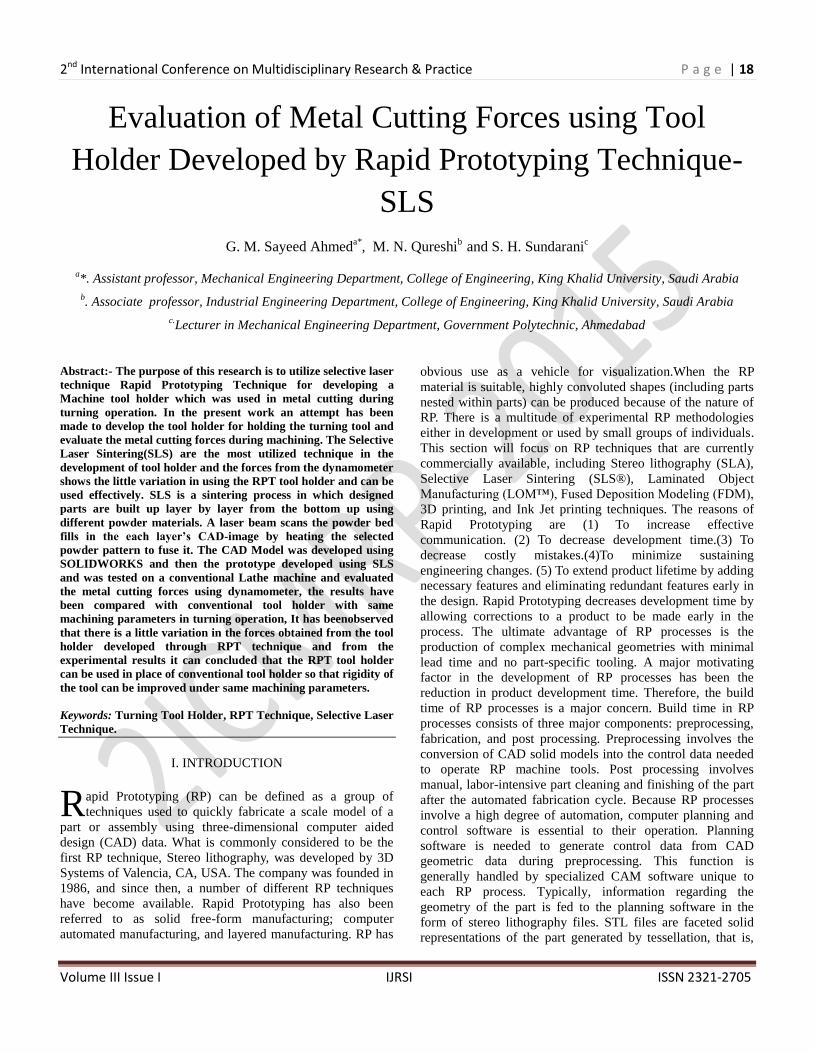
Fig 5: Slicer modulation of EOS RP-Tools
Fig 6: Slicer modulation of EOS RP-Tools
The layers in the SLI file are analyzed using SLIFIX module.
Data errors are detected and corrected automatically. Errors
caused by errors in the STL file are corrected, e.g. overlapping
inverted polygons or duplicated polygons. This module is
used for viewing layer data that are available in SLI or CLI
files, i.e. two-dimensional layer data are displayed with the
aid of polygons. It is very important that the default job
matching the material is loaded. Creating a job, loading parts,
Deleting parts, creating, ungrouping and deleting part groups.
The parts loaded are exposed in the order in which they are
listed in the Job parameters window. Optimal sorting of the
parts prevents unnecessary jumps between the parts during
exposure and therefore reduces the building time. Different
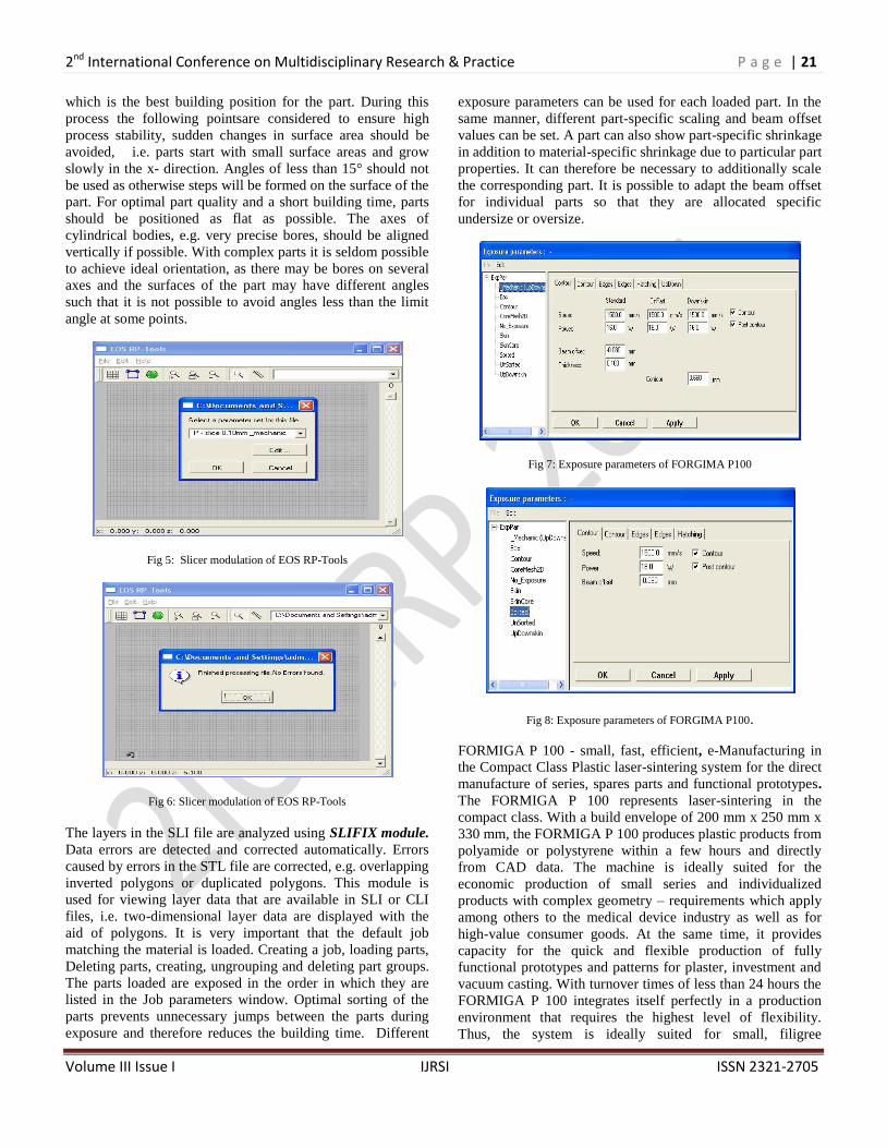
exposure parameters can be used for each loaded part. In the
same manner, different part-specific scaling and beam offset
values can be set. A part can also show part-specific shrinkage
in addition to material-specific shrinkage due to particular part
properties. It can therefore be necessary to additionally scale
the corresponding part. It is possible to adapt the beam offset
for individual parts so that they are allocated specific
undersize or oversize.
Fig 7: Exposure parameters of FORGIMA P100
Fig 8: Exposure parameters of FORGIMA P100.
FORMIGA P 100 - small, fast, efficient, e-Manufacturing in
the Compact Class Plastic laser-sintering system for the direct
manufacture of series, spares parts and functional prototypes.
The FORMIGA P 100 represents laser-sintering in the
compact class. With a build envelope of 200 mm x 250 mm x
330 mm, the FORMIGA P 100 produces plastic products from
polyamide or polystyrene within a few hours and directly
from CAD data. The machine is ideally suited for the
economic production of small series and individualized
products with complex geometry – requirements which apply
among others to the medical device industry as well as for
high-value consumer goods. At the same time, it provides
capacity for the quick and flexible production of fully
functional prototypes and patterns for plaster, investment and
vacuum casting. With turnover times of less than 24 hours the
FORMIGA P 100 integrates itself perfectly in a production
environment that requires the highest level of flexibility.
Thus, the system is ideally suited for small, filigree

2nd International Conference on Multidisciplinary Research & Practice P a g e | 22
Volume III Issue I IJRSI ISSN 2321-2705
components such as connectors, just to name one example.
The revolutionary dosage and recoating system ensures a high
product quality and process stability.
Table 1: Technical Data for FORMIGA P100
Effective building volume 200 mm x 250 mm x 330 mm
Building speed up to 24 mm height/h (0.94 in/h)
Layer thickness typically 0.1 mm (0.004 in)
Laser type CO2, 30W
Precision optics F-theta lens
Scan speed up to 5 m/s (16.4 ft/sec)
Power supply 16 A
Power consumption (nominal)
2 Kw
The plastic powder types are Polyamide powder-unfilled, pure
polyamide powder-filled mixture of polyamide powder and a
filler material with which different mechanical or visual
properties are achieved. Plastic powder from the exchangeable
frames which must be sieved and regenerated before further
usage, The Recommended storage conditions are plastic
powder should be stored in closed powder bins, The room
temperature Room temperature is around 20 - 25 °C with 50
% humidity. The plastic powder from the exchangeable frame
is sieved. Sieving and mixing may cause electrostatic
charging. The plastic power cannot be used immediately.
Store the plastic powder between the individual processing
steps (1)In open powder bins (2) For at least 24 hours at 20 -
25 °C and 50 - 60 % atmospheric humidity (3)Protected
against soiling.(4)If the plastic powder is not further processed
immediately after storage, the powder bins must be
closed.PA2200 is suitable for use in all EOS systems with fine
polyamide option.
Table 2: PA2200 - Material Properties
Average Grain Size 60 µm
Bulk Density 0.435 - 0.445 gm/cm3
Density of Laser Sintered Part 0.9 - 0.95 gm/cm3
Tensile Modulus 1700 ± 150 N/mm2
Tensile Strength 45 ± 3 N/mm2
Elongation at Break 20 ± 5 %
Flexural Modulus 1240 ± 130 N/mm2
Charpy - Notched Impact Strength 4.8 ± 0.3 kJ/m2
Izod - Impact Strength 32.8 ± 3.4 kJ/m2
Ball Indentation Hardness 77.6 ± 2
The mechanical properties on x y z position and the exposure
parameters used. Application PA3200GF is suitable for use in
all EOS systems with polyamide option. The parts fabricated
from this material have excellent mechanical properties, very
smooth surfaces and high accuracy. The recommended layer
thickness is 0.15mm. Unexposed powder can be reused.
Depending on the building time it has to be mixed with fresh
powder by a ratio of 2:1 to 1:1 (old: new) in order to
guarantee constant process parameters and persisting part
quality.
VI. CAD MODEL OF TURING TOOL HOLDER
Solid Works is a Para solid-based solid modeler, and utilizes a
parametric feature-based approach to create models and
assemblies. Parameters refer to constraints whose values
determine the shape or geometry of the model or assembly.
Design intent is how the creator of the part wants it to respond
to changes and updates. For example, you would want the
hole at the top of a beverage can to stay at the top surface,
regardless of the height or size of the can. Solid Works allows
the user to specify that the hole is a feature on the top surface,
and will then honor their design intent no matter what height
they later assign to the can. This shape is then extruded or cut
to add or remove material from the part. Operation-based
features are not sketch-based, and include features such as
fillets, chamfers, shells, applying draft to the faces of a part,
etc. Building a model in Solid Works usually starts with a 2D
sketch (although 3D sketches are available for power users).
The sketch consists of geometry such as points, lines, arcs,
conics (except the hyperbola), and spines. Dimensions are
added to the sketch to define the size and location of the
geometry. Solid Works also includes additional advanced
mating features such as gear and cam follower mates, which
allow modeled gear assemblies to accurately reproduce the
rotational movement of an actual gear train. Finally, drawings
can be created either from parts or assemblies. Views are
automatically generated from the solid model, and notes,
dimensions and tolerances can then be easily added to the
drawing as needed. The drawing module includes most paper
sizes and standard.
2nd International Conference on Multidisciplinary Research & Practice P a g e | 23
Volume III Issue I IJRSI ISSN 2321-2705
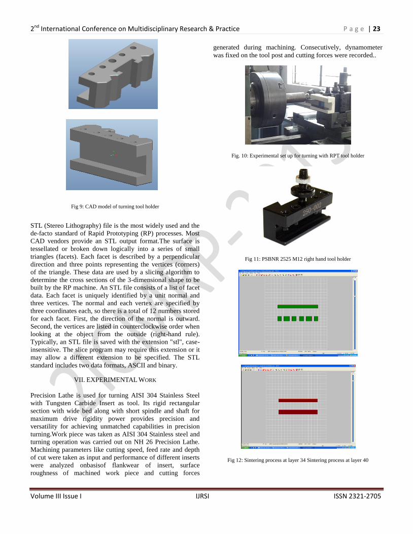
Fig 9: CAD model of turning tool holder
STL (Stereo Lithography) file is the most widely used and the
de-facto standard of Rapid Prototyping (RP) processes. Most
CAD vendors provide an STL output format.The surface is
tessellated or broken down logically into a series of small
triangles (facets). Each facet is described by a perpendicular
direction and three points representing the vertices (corners)
of the triangle. These data are used by a slicing algorithm to
determine the cross sections of the 3-dimensional shape to be
built by the RP machine. An STL file consists of a list of facet
data. Each facet is uniquely identified by a unit normal and
three vertices. The normal and each vertex are specified by
three coordinates each, so there is a total of 12 numbers stored
for each facet. First, the direction of the normal is outward.
Second, the vertices are listed in counterclockwise order when
looking at the object from the outside (right-hand rule).
Typically, an STL file is saved with the extension "stl", case-
insensitive. The slice program may require this extension or it
may allow a different extension to be specified. The STL
standard includes two data formats, ASCII and binary.
VII. EXPERIMENTAL WORK
Precision Lathe is used for turning AISI 304 Stainless Steel
with Tungsten Carbide Insert as tool. Its rigid rectangular
section with wide bed along with short spindle and shaft for
maximum drive rigidity power provides precision and
versatility for achieving unmatched capabilities in precision
turning.Work piece was taken as AISI 304 Stainless steel and
turning operation was carried out on NH 26 Precision Lathe.
Machining parameters like cutting speed, feed rate and depth
of cut were taken as input and performance of different inserts
were analyzed onbasisof flankwear of insert, surface
roughness of machined work piece and cutting forces
generated during machining. Consecutively, dynamometer
was fixed on the tool post and cutting forces were recorded..
Fig. 10: Experimental set up for turning with RPT tool holder
Fig 11: PSBNR 2525 M12 right hand tool holder
Fig 12: Sintering process at layer 34 Sintering process at layer 40
2nd International Conference on Multidisciplinary Research & Practice P a g e | 24
Volume III Issue I IJRSI ISSN 2321-2705
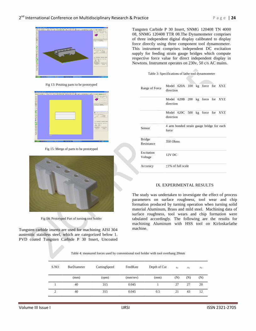
Fig 13: Positing parts to be prototyped
Fig 15: Merge of parts to be prototyped
Fig 14: Prototyped Part of turning tool holder
Tungsten carbide inserts are used for machining AISI 304
austenitic stainless steel, which are categorized below 1.
PVD coated Tungsten Carbide P 30 Insert, Uncoated
Tungsten Carbide P 30 Insert, SNMG 120408 TN 4000
08, SNMG 120408 TTR 08.The Dynamometer comprises
of three independent digital display calibrated to display
force directly using three component tool dynamometer.
This instrument comprises independent DC excitation
supply for feeding strain gauge bridges which compute
respective force value for direct independent display in
Newtons. Instrument operates on 230v, 50 c/s AC mains.
Table 3: Specifications of lathe tool dynamometer
IX. EXPERIMENTAL RESULTS
The study was undertaken to investigate the effect of process
parameters on surface roughness, tool wear and chip
formation produced by turning operation when turning solid
material Aluminum, Brass and mild steel. Machining data of
surface roughness, tool wears and chip formation were
tabulated accordingly. The following are the results for
machining Aluminum with HSS tool on Kirloskarlathe
machine.
Table 4: measured forces used by conventional tool holder with tool overhang 20mm
Range of Force Model 620A 100 kg force for XYZ
direction
Model 620B 200 kg force for XYZ
direction
Model 620C 500 kg force for XYZ
direction
Sensor 4 arm bonded strain gauge bridge for each
force
Bridge
Resistance 350 Ohms
Excitation
Voltage 12V DC
Accuracy +1% of full scale
S.NO BarDiameter CuttingSpeed FeedRate Depth of Cut Fx Fy Fz
(mm) (rpm) (mm/rev) (mm) (N) (N) (N)
1 40 315 0.045 1 27 27 20
2 40 315 0.045 0.5 21 43 12

2nd International Conference on Multidisciplinary Research & Practice P a g e | 25
Volume III Issue I IJRSI ISSN 2321-2705
Table 5: Measured forces used by conventional tool holder with tool overhang 30mm
Table 6: Forces developed by conventional tool holder and RPT tool holder
Conventional Tool Holder RPT Tool Holder
S.NO Fx Fy Fz Fx Fy Fz % variation
1 30 30 20 27 32 20 1.25
2 20 40 10 25 32 12 1.43
3 20 40 10 27 31 10 2.86
4 10 30 20 14 28 17 1.67
5 10 20 10 12 17 10 2.50
6 10 20 0 11 18 0 3.33
7 10 20 20 12 19 18 2.00
8 10 20 30 12 21 25 3.33
9 10 10 0 11 9 0 0.00
3 40 315 0.045 0.25 21 43 10
4 40 500 0.045 1 12 32 12
5 40 500 0.045 0.5 12 22 10
6 40 500 0.045 0.25 12 22 0
7 40 775 0.045 1 12 22 18
8 40 775 0.045 0.5 12 22 27
9 40 775 0.045 0.25 12 8 0
S.NO Bar
Diameter
Cutting
Speed
Feed
Rate
Depth
Of Cut Fx Fy Fz
1 40 315 0.045 1 20 80 10
2 40 315 0.045 0.5 20 10 10
3 40 315 0.045 0.25 20 20 0
4 40 500 0.045 1 30 10 90
5 40 500 0.045 0.5 10 40 10
6 40 500 0.045 0.25 10 20 10
7 40 775 0.045 1 20 40 10
8 40 775 0.045 0.5 20 20 10
9 40 775 0.045 0.25 10 10 40

2nd International Conference on Multidisciplinary Research & Practice P a g e | 26
Volume III Issue I IJRSI ISSN 2321-2705
Table 7: % of variation between conventional and RPT tool holder
Conventional tool holder RPT tool holder
S.NO MRR. (mm3/min) MRR, (mm3/min) % variation
1 3.12 3.22 3.11
2 4.16 4.21 1.19
3 4.16 4.26 2.35
4 3.12 3.18 1.89
5 2.08 2.13 2.35
6 2.08 2.16 3.70
7 2.08 2.14 2.80
8 3.12 3 4.00
9 1.04 1.06 1.89
Fig 15: Forces obtained by Dynamometer with Conventional and RPT tool Holder, Forces obtained by using tool over hang 23mm with different depth of cut for
RPT tool holder
Fig 16: Forces obtained by Dynamometer with Conventional and RPT tool Holder at Cutting Speed at 500RPM and 775 RPM
0
10
20
30
40
50
60
70
80
90
1 0.5 0.25
Fx
Fy
Fz
0
5
10
15
20
25
30
1 0.5 0.25
Fx
Fy
Fz
0
5
10
15
20
25
30
1 0.5 0.25
Fx
Fy
Fz
0
5
10
15
20
25
1 0.5 0.25
Fx
Fy
Fz

2nd International Conference on Multidisciplinary Research & Practice P a g e | 27
Volume III Issue I IJRSI ISSN 2321-2705
X. CONCLUSION
In rapid prototyping using additive fabrication, the physical,
real and the virtual components all have similar features can
be manufactured. In the present project RPT technique is used
to develop the tool holder and used in turning operation. By
the application of the developed RPT model it has been
observed the tool holder with a lighter weight and more rigid
performing the same function as that of conventional tool
holder and on mass production the cost price will also be
less.It has been observed that the measured forces from the
dynamometer with and without RPT Tool holder is around
3%.Thus the tool holder developed from the RPT Technique
is also rigid and provide good rigidity during machining. The
results also revealed that using a long tool length may set
excessive vibrations that could be efficiently controlled by the
use of short tool length. With a long tool length, the cutting
variables become important factors to control in order to
significantly improve surface roughness results no matter
what type of bar is used.With the developed RPT tool holder
detection with different combination of machine parameters.
Design modification can be made to arrange multiple tools in
a single slot of the tool holder. Developing the tool holder
with different RPT techniques to include strain based sensors
in the prototype for measuring deflection of the tool.The
measured forces in the present work was recorded by a
dynamometer, which is relatively expensive only and usually
inconvenient for industrial applications. Other types of
sensors, particularly accelerometers, may potentially replace
the dynamometer due to their lower cost and easy installation.
RPT technique can be implemented for manufacturing a
various industrial components in future.
REFERENCES
[1]. J. G. Conley and H. L. Marcus, "Rapid Prototyping and Solid
Freeform Fabrication,"ASME Transactions - Journal of
Manufacturing Science and Engineering, vol. 119, no.4B,
November 1997, pp. 811-816.
[2]. J. P. Kruth, “Material Incress Manufacturing by Rapid Prototyping
Techniques," CIRPAnnals, vol. 40, no. 2, 1991, pp. 603-614.
[3]. Stacey Au and Paul K. Wright, "A Comparative Study of Rapid
Prototyping Technology," Intelligent Concurrent Design:
Fundamentals, Methodology, Modeling, and Practice, DE-vol. 66,
ASME, New Orleans, Louisiana, November / December 1993,
pp.73-82.
[4]. Marshall Burns, Automated Fabrication: Improving Productivity
in Manufacturing, Englewood Cliffs, New Jersey: PTR Prentice
Hall, 1993.
[5]. D. Kochan, ed., Solid Freeform Manufacturing, Manufacturing
Research and Technology Series, vol. 19, Amsterdam: Elsevier,
1993.
[6]. Paul F. Jacobs, Rapid Prototyping & Manufacturing:
Fundamentals of Stereo Lithography, Dearborn, Michigan: Society
of Manufacturing Engineers, 1992.
[7]. Paul F. Jacobs, Stereo lithography and other RP&M Technologies:
From Rapid Prototyping to Rapid Tooling, Dearborn, Michigan:
Society of Manufacturing Engineers, 1996.
[8]. J. J. Beaman, J. W. Barlow, D. L. Bourell, R. H. Crawford, H. L.
Marcus, and K. P.McAlea, Solid Freeform Fabrication - A New
Direction in Manufacturing, Dordrecht:Kluwer Academic
Publishers, 1997.
[9]. Friedrich B. Prinz, Chair, Rapid Prototyping in Europe and Japan,
Vol. I, Analytical Chapters, Baltimore: International Technology
Research Institute, Loyola College in Maryland, March 1997.
[10]. Rapid Prototyping Report - The Newsletter of the Desktop
Manufacturing Industry, San Diego: CAD/CAM Publishing, Inc.
[11]. Terry Wohlers, Rapid Prototyping and Tooling State of the
Industry: 1998 Worldwide Progress Report, Fort Collins,
Colorado: Wohlers Associates, Inc., 1998.
[12]. http://www.patents.ibm.com or http://patent.womplex.ibm.com
[13]. Terry Wohlers, Rapid Prototyping and Tooling State of the
Industry: 1998 Worldwide Progress Report, Fort Collins,
Colorado: Wohlers Associates, Inc., 1998.
[14]. C. R. Deckard, "Selective Laser Sintering," PhD Thesis, The
University of Texas at Austin, Austin, Texas, 1988.
[15]. Rapid Prototyping Report - The Newsletter of the Desktop
Manufacturing Industry, March 1997, p. 6.