evaluation of lightning arrestor by using matlab
TRANSCRIPT
EVALUATION OF LIGHTNING ARRESTOR BY
USING MATLAB
DISSERTATION
Submitted in partial fulfillment of the requirement for the award of the
degree of
MASTER OF TECHNOLOGY
IN
(Electrical Engineering)
By
GAURAV SHARMA
Under the Guidance of
Mr. ANSHUL MAHAJAN
School of Electrical and Electronics Engineering
Lovely Professional University
Punjab
MAY-2015

ii
CERTIFICATE
This is to certify that the DISSERTATION titled “EVALUATION OF LIGHTNING
ARRESTOR BY USING MATLAB” that is being submitted by “GAURAV SHARMA” is in
partial fulfillment of the requirements for the award of MASTER OF TECHNOLOGY DEGREE
IN ELECTRICAL ENGINEERING, is a record of bonafide work done under my guidance. The
contents of this DISSERTATION,is full or in parts, have neither been taken from any other source
nor have been submitted to any other institute or University for award of any degree or diploma and
the same is certified.
Mr. ANSHUL MAHAJAN
ASSISTANT PROFESSOR
LOVELY PROFESSIONAL UNIVERSITY
DATE:

iii
ABSTRACT
Nowadays, to operate the electrical energy in steady state is the major problem due to the
faults or disturbances occur in the power system. The disturbances occur due to on and off of the
system, lightning occurrences, or due to the symmetrical and unsymmetrical faults. The magnitude
of voltage and current increases as compared to the steady state due to change in circuit conditions
i.e. opening and closing of the switches, or occurrence of a natural fault such as lightning,
discharge.
Maximum overvoltage across the system is due to the overvoltage which affects the steady
state stability of the system and makes the system faulty. When there is overvoltage on the
transmission line it rapidly increases the magnitude of voltage and current in the system and
disturbs the stability of the system due to which system gets switched off. To protect the system
from overvoltage disturbances lightning surge arrestors are used.
In this report we are protecting the system from getting damaged by the overvoltage
developed across the system (due to switching or lightning). For analyzing the system we are
consider two cases of overvoltage i.e. lightning and switching. In this report we emphasize the
impact of protection technique used for protecting the various equipment from overvoltage develop
across the system.
All the simulating work is done in MATLAB/Simulink in which we developed different
graphical relationship between current, voltage waveforms with respect to time. All the simulation
is done by inducing lightning on different points on the transmission line and then comparison is
made, then considering the results by using arrestor model and without using arrestor model. In the
last we concluded that it is preferable to use arrestor across the line to protect the compensated
devices across the system because the arrestor protective device operates immediately in order to
remove the heavy overvoltage to pass through the compensated devices.

iv
ACKNOWLEDGEMENT
I am grateful to the individuals who contributed their valuable time towards my report work. I wish
to express my sincere and heart full gratitude to my DISSERTATION guide Mr. ANSHUL
MAHAJAN, professor in Electrical and Electronics Department, who guides me to took up this
DISSERTATION in sync with global trends in scientific approach.
I thank with the deep sense of gratitude to Mr. ANSHUL MAHAJAN, for his constant
encouragement and cooperation during DISSERTATION for forecasting an excellent academic
environment which made my DISSERTATION work possible. I also thank to HOD, HOS, entire
faculty members and fellow classmates.
I thank with the deep sense of gratitude to my parents, for there constant encouragement and
cooperation which made my DISSERTATION work possible.
GAURAV SHARMA
Reg. No. 11302031

v
DECLARATION
I GAURAV SHARMA, student of M.TECH POWER SYSTEMS under Department of
ELECTRICAL AND ELECTRONICS ENGINEERING of lovely professional university,
Punjab, hereby declare that all the information furnished in this Dissertation report is based on my
own intensive research and is genuine.
This Dissertation does to the best of my knowledge; contain part of my work which has been
submitted for the award of my degree either of this university or any other university without
proper citation.
GAURAV SHARMA
Registration No. 11302031
Date:

vi
TABLE OF CONTENTS
PAGE NO.
CERTIFICATE ii
ABSTRACT iii
ACKNWLEDGEMENT iv
DECLARATION v
LIST OF FIGURES ix
LIST OF TABLES xii
CHAPTER 1
INTRODUCTION
1.1 INTRODUCTION 1
1.2 OVERVOLTAGE 2
1.3 LIGHTNING 2
1.3.1 LIGHTNING FORMATION 3
1.3.2SOME LIGHTNING FACTS 4
1.3.3CHARACTERISTICS OF LIGHTNING STROKES 4
1.3.4 OVERVOLTAGE DUE TO LIGHTNING 5
1.3.4.1 OVERVOLTAGE DUE TO DIRECT LIGHTNING STROKES 5
1.3.4.2 OVERVOLTAGE DUE TO INDIRECT LIGHTNING STROKES 6
1.3.5 LINE DESIGN BASED ON DIRECT STROKES 7
1.3.6 PROTECTION AGAINST LIGHTNING 7
1.3.7 LIGHTNING ARRESTOR 8
1.3.8 CALCULATION OF ARRESTOR VOLTAGE AND CURRENT 9
1.3.9 LIGHTNING PROTECTION OF LOW VOLTAGE INSTALLATION 12

vii
1.3.10 EFFECT OF LIGHTNING CURRENT 12
1.4 SWITCHING OVERVOLTAGES 13
1.4.1 ORIGIN OF SWITCHING OVERVOLTAGES 13
1.4.2 OTHER SWITCHING OPERATION 14
CHAPTER 2
LITERATURE SURVEY
2.1 INTRODUCTION 15
2.2 RELATED WORK 15
2.3 PRESENT WORK 20
CHAPTER 3
WORK DONE
3.1 PROBLEM FORMULATION 21
3.2 OBJECTIVES 21
3.3 TOOLS 22
3.3.1 MATLAB/SIMULINK 22
3.4 RESEARCH METHOLOGY 22
CHAPTER 4
RESULTS AND DISCUSSION
4.1 BASIC DETAILS OF SIMULATING MODEL 29
4.2 SUBSYSTEM USED IN THE MODEL 29
4.3 SIMULATION CRITERIA 31
4.3.1 SWITCHING OVERVOLTAGE 31
4.3.1.1SWITCHING OVERVOLTAGE ACROSS
COMPENSATION DEVICES 31
4.3.2 LIGHTNING OVERVOLTAGE 35
4.3.2.1 OCCURANCE OF LIGHTNING BEFORE
SERIES CAPACITOR 35

viii
4.3.2.2 OCCURANCE OF LIGHTNING AFTER
SERIES CAPACITOR 39
4.4 SIMULATION RESULTS 42
CHAPTER 5
CONCLUSION AND FUTURE SCOPE
5.1 CONCLUSION 47
5.2 FUTURE SCOPE 47
REFERENCES 48
APPENDIX
GLOSSARY OF TERMSS 51
ABBREVIATIONS 52

ix
List of Figures Page No.
1.1 Basic block diagram of overvoltage develop across the system 2
1.2 Representation of lightning formulation in the atmosphere 3
1.3 Represent the characteristics of lightning strokes 4
1.4 Direct lightning strike on the roof of the building 5
1.5 Direct lightning strike on overhead low voltage line 6
1.6 Overvoltage due to indirect lightning 7
1.7 Surge arrester internal structure 9
1.8 The Characteristics of surge arrestor 9
1.9 Surge arrester at the end of a line actual circuit 10
1.10 Surge arrester at the end of a line equivalent circuit 10
1.11 Surge arrester at the junction of two line actual circuit 11
1.12 Surge arrester at the junction of two line equivalent circuit 11
3.1 A single phase MATLAB/Simulink model of switching overvoltages without using
arrestor 23
3.2 A single phase MATLAB/Simulink model of switching overvoltage by arrestor 24
3.3 A single phase MATLAB/Simulink model lightning overvoltage before series capacitor
without using arrestor 25
3.4 A single phase MATLAB/Simulink model of lightning overvoltage before series capacitor
by arrestor 26
3.5 A single phase MATLAB/Simulink model lightning overvoltage after series capacitor
without using arrestor 26
3.6 A single phase MATLAB/Simulink model of lightning overvoltage after series capacitor
by using arrestor 27
3.7 Simulink model of impulse generator 28
4.1 Represent the Voltage Vs Time wave generator which act as
lightning voltage source 30

x
4.2 Represent the Voltage Vs Time wave generator which act as
lightning voltage source 30
4.3 Volatge Vs Time and Current Vs Time waveform of the shunt reactor at
Sending end of transmission line, Switching overvoltage without using
Arrestor 32
4.4 Volatge Vs Time and Current Vs Time waveform of the series capacitor at
Midpoint of transmission line, Switching overvoltage without using
Arrestor 32
4.5 Volatge Vs Time and Current Vs Time waveform of the shunt reactor at
Receiving end of transmission line, Switching overvoltage without using
Arrestor 33
4.6 Volatge Vs Time and Current Vs Time waveform of the shunt reactor at
Sending end of transmission line, Switching overvoltage by using
Arrestor 34
4.7 VolatgeVs Time and Current Vs Time waveform of the series capacitor at
Midpoint of transmission line, Switching overvoltage by using
Arrestor 34
4.8 VolatgeVs Time and Current Vs Time waveform of the shunt reactor at
Receiving end of transmission line, Switching overvoltage by using
Arrestor 34
4.9 VolatgeVs Time and Current Vs Time waveform of the shunt reactor at
Sending end of transmission line, lightning overvoltage before
series capacitor without using arrestor 36
4.10 VolatgeVs Time and Current Vs Time waveform of the series capacitor at
midpoint of transmission line, lightning overvoltage before
series capacitor without using arrestor 36
4.11 VolatgeVs Time and Current Vs Time waveform of the shunt reactor at
receiving end of transmission line, lightning overvoltage before
series capacitor without using arrestor 37

xi
4.12 VolatgeVs Time and Current Vs Time waveform of the shunt reactor at
Sending end of transmission line, lightning overvoltage before
series capacitor by using arrestor 38
4.13 VolatgeVs Time and Current Vs Time waveform of the series capacitor at
midpoint of transmission line, lightning overvoltage before
series capacitor by using arrestor 38
4.14 VolatgeVs Time and Current Vs Time waveform of the shunt reactor at
receiving end of transmission line, lightning overvoltage before
series capacitor by using arrestor 38
4.15 VolatgeVs Time and Current Vs Time waveform of the shunt reactor at
Sending end of transmission line, lightning overvoltage after
series capacitor without using arrestor 39
4.16 VolatgeVs Time and Current Vs Time waveform of the series capacitor at
midpoint of transmission line, lightning overvoltage after
series capacitor without using arrestor 40
4.17 VolatgeVs Time and Current Vs Time waveform of the shunt reactor at
receiving end of transmission line, lightning overvoltage after
series capacitor without using arrestor 40
4.18 A single phase MATLAB/Simulink model of 735KV transmission system
Feed a load through a 200Km transmission line, lightning overvoltage
After series capacitor by using arrestor 41
4.19 VolatgeVs Time and Current Vs Time waveform of the shunt reactor at
Sending end of transmission line, lightning overvoltage after
series capacitor by using arrestor 41
4.20 VolatgeVs Time and Current Vs Time waveform of the series capacitor at
midpoint of transmission line, lightning overvoltage after
series capacitor by using arrestor 42

xii
LIST OF TABLES PAGE NO.
1.1 Method adopted for protecting the electrical equipment from lightning strokes 8
4.1 Switching overvoltage without using arrestor 32
4.2 Switching overvoltage by using arrestor 33
4.3 Lightning overvoltage before series capacitor without using arrestor 36
4.4 Lightning overvoltage before series capacitor by using arrestor 37
4.5 Lightning overvoltage after series capacitor without using arrestor 39
4.6 Lightning overvoltage after series capacitor by using arrestor 41
4.7 Comparison between switching overvoltage with arrestor and without
arrestor model 42
4.8 Comparison between lightning overvoltage before series capacitor
with arrestor and without arrestor model 44
4.8 Comparison between lightning overvoltage before series capacitor
with arrestor and without arrestor model 45

1
CHAPTER 1
INTRODUCTION
1.1 INTRODUCTION
Overvoltage is one of the major problem occurring in the power system and to
minimise this problem many methods, equipment’s and techniques have used. It is of two
types i.e. lightning and switching. To improve the performance of the power system from
lighting several studies has been conducted and many methodologies have been proposed in
the technical literature over the last decades. The most important safeguard in electrical
power system is to protect overhead high voltages transmission line from lightning strokes.
Accurate evaluation of the lightning performance helps to make the system highly efficient.
Shield wires and surge arrestors are used for the protection of lines from lightning. Due to the
lightning phenomena overvoltage occurs which reduces the reliability of electrical network,
leading to interruption and as a consequence increases the transmission line repair cost. To
minimize the annual failure of the line overhead ground wires are placed above the phases to
intercept lightning strokes[2] . Surge arrestors are the main measures, which are used in order
to protect the system against lightning and switching phenomena.
Franklin‟s invention of lightning rod to be protects apparatus from lightning strikes.
Till today for more than 200 years, the lightning rod has been used for air terminal of
lightning protection systems [6] But lightning rods cannot always function perfectly because
they have an unexpected shielding failures, are often due to the improbability of lightning
phenomenon. For example, several direct strikes to the transformer substations took place in
the power grid of north India. For designing a lightning protection system, the protection
angle method, the rolling sphere method and the mesh method are used to evaluate the
protection zone of a lightning rod, all of these fall considerations on stochastic behaviours of
the lightning process. The effectiveness of lightning rods is investigated by means of dynamic
simulation of lightning strikes including stochastic [19].
Over voltages in the power system may be due to the lightning strokes that terminate
on or near to power lines such over voltages are known as lightning over voltage or surges.
Switching over voltages or surges is due to the certain change in the circuit condition brought

2
about by deliberate or unintentional switching operation[15]. The magnitude of lightning over
voltage is essentially independent of system voltage is known as external over voltages.
1.2 OVERVOLTAGE
When the voltage across the system increased to very high value than its normal voltage
flowing in the system, the increased voltage which is beyond the upper limit of voltage across
the system is known as overvoltage. The overvoltage is one of the most dangerous condition
arises across the system. The overvoltage across the system depends on duration that whether
it’s a transient or a voltage spike or permanent [16]. There are two types of overvoltage occur
in the system.
Natural: - The natural source of overvoltage is lightning.
Man-made:-Man made source of overvoltage usually caused by switching
Figureure1.1Basic block diagram of different overvoltage develop across the system
1.3 LIGHTNING OPERATION
Lightning is a phenomenon that occurs in nature. The energy contained in a lightning
stroke is very high and it can be tremendously destructive. Lighting strokes are unprotected to
electric distribution networks. A single stroke to a distribution line is sufficient to cause a
OVERVOLTAGE
INTERNAL EXTERNAL
SWITCHING
OPERATION
LIGHTNING
OPERATION
DIRECT
LIGHTNING
INDIRECT
LIGHTNING
TIME FRAME
to
TIME FRAME
to
3
blackout throughout a feeder and to prevent this type of problems power systems are
protected with lightning rods, ground wires and lightning arrestors. Overhead high voltage
transmission lines and to reduce the failure rate, arrestors are installed between each phase
and earth to protect the system [2].
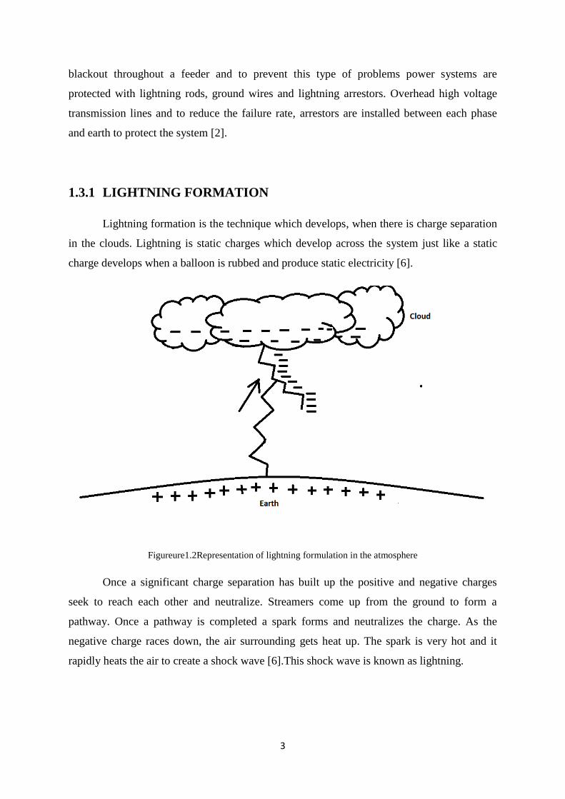
1.3.1 LIGHTNING FORMATION
Lightning formation is the technique which develops, when there is charge separation
in the clouds. Lightning is static charges which develop across the system just like a static
charge develops when a balloon is rubbed and produce static electricity [6].
Figureure1.2Representation of lightning formulation in the atmosphere
Once a significant charge separation has built up the positive and negative charges
seek to reach each other and neutralize. Streamers come up from the ground to form a
pathway. Once a pathway is completed a spark forms and neutralizes the charge. As the
negative charge races down, the air surrounding gets heat up. The spark is very hot and it
rapidly heats the air to create a shock wave [6].This shock wave is known as lightning.

4
1.3.2 SOME LIGHTNING FACTS
There are 100 lightning strikes a second happening worldwide.
There are more than 8lakh lightning bolts per day.
Lightning flash is about 4.5 Km long but only a centimetre wide
A lightning strike discharges about 1-10 lakhs joules of energy and produces a current
of 30,000 to50,000 amperes.
A single lightning bolt has as much energy as blowing up a ton of TNT.
1.3.3 CHARACTERISTICS OF LIGHTNING STROKES
Lightning strokes characteristics are studied by investigating a large number of aspects:-
Lightning strokes are of negative polarity.
Total surge report occur in the power system are7 to 18% strokes on transmission
lines,37% distribution lightning arrestor surges and 12% station lightning arrestor
Time taken by a lightning stroke may be 1 sec or so.
A lightning stroke may contain peak current from 1kA to 200kA or so. Figure1.1
shows the distribution of peak value of lightning current.
The time to first peak is between zero and 10 microseconds. The time to half value on
the tail is between 5 and 90 microseconds [6].
Figureure1.3 Represent the characteristics of lightning strokes

5
1.3.4 OVERVOLTAGE DUE TO LIGHTNING
When the lightning occurs in the system the voltage develops across the system
becomes too high. Basically lightning is a natural phenomenon in which voltage value may
be high and low energy level. The direct lightning strike on the conductor or roof of the
system it will damage the system or equipment being installed in the system. The over
voltage develops across the system is more than the 20 times the normal voltage develop
across the system which harms the rating of the equipment being installed in the system. The
over voltage may be due to direct lightning strokes or may be indirect lightning strokes[6].
1.3.4.1 OVERVOLTAGE DUE TO DIRECT LIGHTNING STROKES
These can be in two forms:
When lightning strike the conductor:- When lightning strikes on the lightning
conductor or on the roof of a building which is earthed or grounded, the lightning
current goes into the ground through the ground wire. The impedance of the ground
and the current flowing through the conductor develops large potential difference, this
is overvoltage. This overvoltage then propagates throughout the building all the way
through the cables and damaged the equipment present in the system.
Figure1.4 Direct lightning strike on the roof of the building
6
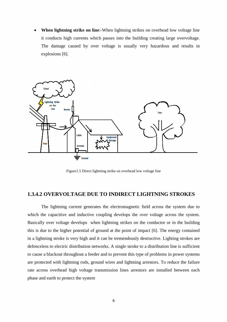
When lightning strike on line:-When lightning strikes on overhead low voltage line
it conducts high currents which passes into the building creating large overvoltage.
The damage caused by over voltage is usually very hazardous and results in
explosions [6].
Figure1.5 Direct lightning strike on overhead low voltage line
1.3.4.2 OVERVOLTAGE DUE TO INDIRECT LIGHTNING STROKES
The lightning current generates the electromagnetic field across the system due to
which the capacitive and inductive coupling develops the over voltage across the system.
Basically over voltage develops when lightning strikes on the conductor or in the building
this is due to the higher potential of ground at the point of impact [6]. The energy contained
in a lightning stroke is very high and it can be tremendously destructive. Lighting strokes are
defenceless to electric distribution networks. A single stroke to a distribution line is sufficient
to cause a blackout throughout a feeder and to prevent this type of problems in power systems
are protected with lightning rods, ground wires and lightning arrestors. To reduce the failure
rate across overhead high voltage transmission lines arrestors are installed between each
phase and earth to protect the system

7
Figure1.6 Overvoltage due to indirect lightning
1.3.5 LINE DESIGN BASED ON DIRECT STROKES
The basic principles to protect system from direct lightning strike are:
There should be supply with ground wire of sufficient mechanical strength to shield
the phase conductors from direct lightning strokes.
There must be adequate clearance from the phase conductor to the tower so that full
effectiveness of the insulating structure can be obtained.
There must be adequate clearance from the phase conductor and the ground wire
especially at mid span so that flashover between phase conductor and ground wire are
eliminated
The tower footing resistance should be as low as economically justified. A tower
footing resistance helps in maintaining the tower top voltages to a safe value[3].
1.3.6 PROTECTION AGAINST LIGHTNING
Lightning produces high magnitude of current and voltage in the system. So to protect the
electrical equipment from being damaged from lightning stroke following techniques are to
be studied:-
Transmission line protection from direct lightning strokes.
Substation and power station protection from direct lightning strokes
8
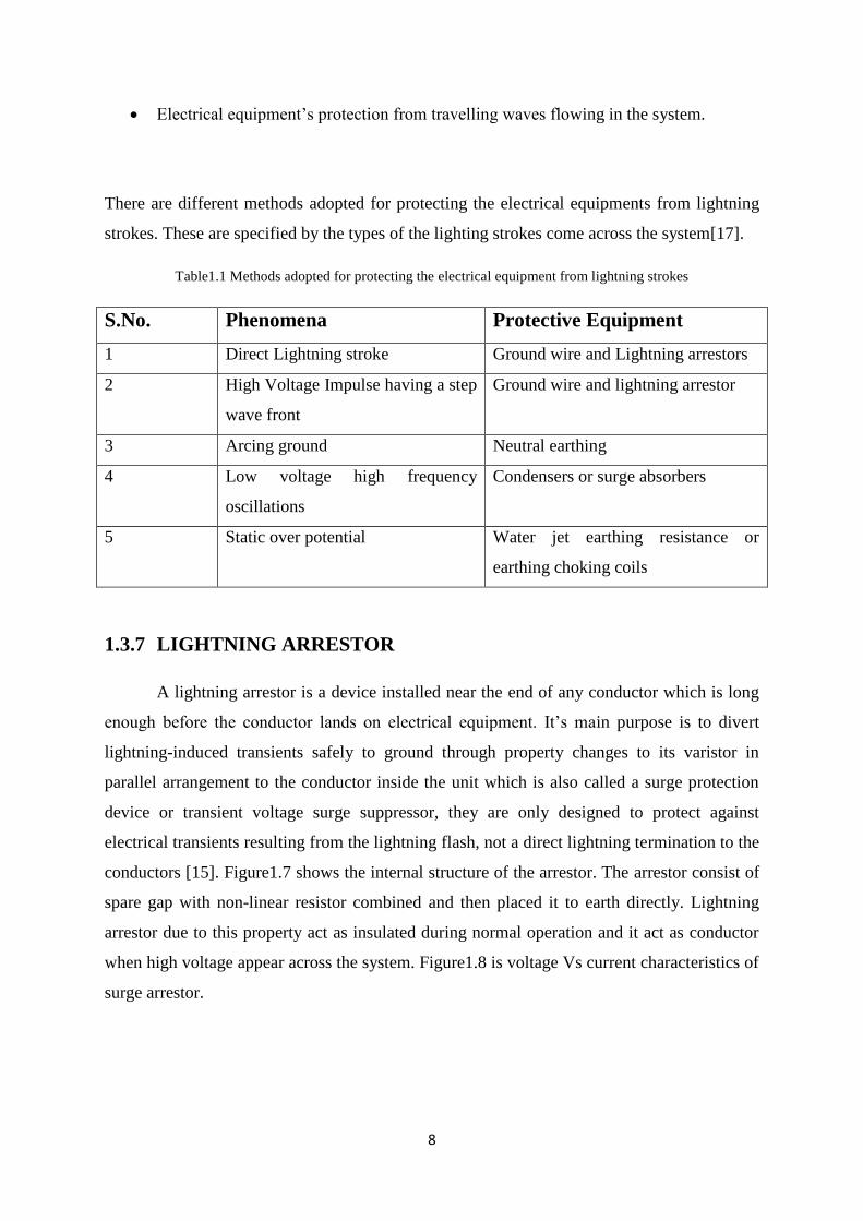
Electrical equipment’s protection from travelling waves flowing in the system.
There are different methods adopted for protecting the electrical equipments from lightning
strokes. These are specified by the types of the lighting strokes come across the system[17].
Table1.1 Methods adopted for protecting the electrical equipment from lightning strokes
S.No. Phenomena Protective Equipment
1 Direct Lightning stroke Ground wire and Lightning arrestors
2 High Voltage Impulse having a step
wave front
Ground wire and lightning arrestor
3 Arcing ground Neutral earthing
4 Low voltage high frequency
oscillations
Condensers or surge absorbers
5 Static over potential Water jet earthing resistance or
earthing choking coils
1.3.7 LIGHTNING ARRESTOR
A lightning arrestor is a device installed near the end of any conductor which is long
enough before the conductor lands on electrical equipment. It’s main purpose is to divert
lightning-induced transients safely to ground through property changes to its varistor in
parallel arrangement to the conductor inside the unit which is also called a surge protection
device or transient voltage surge suppressor, they are only designed to protect against
electrical transients resulting from the lightning flash, not a direct lightning termination to the
conductors [15]. Figure1.7 shows the internal structure of the arrestor. The arrestor consist of
spare gap with non-linear resistor combined and then placed it to earth directly. Lightning
arrestor due to this property act as insulated during normal operation and it act as conductor
when high voltage appear across the system. Figure1.8 is voltage Vs current characteristics of
surge arrestor.

9
Figure 1.7 Surge arrestor internal structure
Figure 1.8 The Characteristics of surge arrestor
1.3.8 CALCULATION OF ARRESTOR VOLTAGE AND CURRENT
ARRESTOR AT THE END OF A LINE
An arrestor connected at the end of the line of surge impedance 𝑍𝑐 and a wave 𝑒𝑓 travelling
on the line.

10
Figure 1.9 Surge arrestor at the end of a line actual circuit
Figure 1.10 Surge arrestor at the end of a line equivalent circuit
Figure1.9 shows the surge arrestor at the junction of a line actual circuit. This is the
basic diagram of arrestor installation in parallel to lines for protecting the system from being
damaged. Figure1.10 is the equivalent circuit of the actual circuit of arrestor installation for
calculating the current present across the arrestor installed in the system.
𝑒 𝑒 𝑍 ---------------1.1
𝑒 -----------------------1.2
Where 𝑒 forward voltage, 𝑒 arrestor voltage, 𝑍 surge impedance,
Arrestor current

11
ARRESTOR AT JUNCTION OF TWO LINES
Arrestor at the junction of two lines having surge impedances 𝑍1 and 𝑧2
Figure 1.11 Surge arrestor at the junction of two line actual circuit
Figure 1.12 Surge arrestor at the junction of two line equivalent circuit
Figure1.11 shows the surge arrestor at the junction of two line actual circuit. This is
the basic diagram of arrestor installation in the system between the two lines for protecting
the system from being damaged. Figure1.12 is the equivalent circuit of the actual circuit of
arrestor installation for calculating the current present across the arrestor installed in the
system.
𝑒 𝑒 𝑍 ----------------- -1.3
𝑒 𝑒 𝑍
---------1.4
𝑒 𝑒 (
) 𝑍 --------1.5
𝑒 ------------------------1.6

12
Where 𝑒 forward voltage, 𝑒 arrestor voltage, 𝑍 surge impedance,
Arrestor current, 𝑍 surge impedance of line 1
𝑍 Surge impedance of line 2
In the above equations the surge impedance plays a very important role in limiting the
voltage across the arrestor. If 𝑍𝑐 and 𝑍1 = 0 i.e. line is absent, the voltage 𝑒𝐴 is equal to2𝑒𝑓.
An arrestor as a separate entity does not limit the voltage. It is only through the combination
of arrestor characteristics and line surge impedance that we can limit the voltage across the
equipment [6].
1.3.9 LIGHTNING PROTECTION OF LOW VOLTAGE INSTALLATION
Lighting can cause huge damage to low voltage installation. These installations
include towering buildings, communication lines, equipment’s and other similar facilities.
Lighting may travel on power lines and enter these installations through power lines.
Lightning protection scheme involves five basic steps:
It Capture the lightning stroke through an air terminal
The system Conduct the lightning current to earth through a down conductor
Scatter energy of lightning stroke allows impedance earthing system
It avoid earth loops and potential differentials
It protect the equipment’s installed from surge travelling on power lines
1.3.10 EFFECT OF LIGHTNING CURRENT
The following effects are noticed if we select and place wrong arrestor in the system.
Thermal effects: When there is lightning the system get heated up due to the increase
in the current in the system. Sometimes it catches fire when the value of current
increases.
Electrodynamics effects: The attraction and repulsion force present in the system
current increases, due to which the wire of the system breaks.
Combustion effects: The shock waves present in the system are transformed into
sound waves which are being heard by us as the sound of thunder. This thunder effect
produces combustion effect in the system.
13
This explains indirect strokes of lightning increase voltage and the breakdown of
equipment. This effect ledS to physical and catastrophic failures initiating industrial/domestic
fire outbreaks, equipment failure, loss of lives and downtime revenue loss and not only make
the system discontinuous but create other losses also.
Hence it is important to understand damage caused due to lightning and provide best
protection against lightning hazard using international standards.
1.4 SWITCHING OVERVOLTAGES
Another method of overvoltage occurrence in the system is switching operation. The
increase in transmission voltage needs to fulfil the requirement of increase transmission
powers, switching surges have become the main factor for designing of insulation for the
transmission line. In the meantime the lightning overvoltage which is a source of external
overvoltage develops across the system comes as a secondary factor in the transmission line
protection [1]. There are two fundamental reasons for this shift in relative importance from
lightning surges as higher transmission voltages are called for:
Over-voltages developed on the transmission line by lightning strokes are only
slightly dependent on the power system voltages. As a result of this the magnitude
relative to the system peak voltage decrease as later it increase.
External insulation has breakdown strength lowest under surge whose fronts fall in the
range 50-500 micro sec. which is typically for the switching surges develop in the
system.
1.4.1 ORIGIN OF SWITCHING OVERVOLTAGES
There are many methods or faults occur in the system due to which the switching
operation takes place. The origin of such over-voltages develop across the system cause
various type of disturbances in the system and make the system faulty to work in the strong
condition.
The various types of switching operations develop across the system are:
ENERGIZATION OF TRANSMISSION LINES AND CABLES:- The specific
switching operation occur in this category which makes the system faulty are:

14
a. Energization of a line that is open circuited at the far end
b. Energization of a line that is terminated by a unloaded transformer
c. Energization of a line through the low voltage side of the transformer
RE-ENERGIZATION OF THE LINE:- Re-energization of the line means the
energization of the line carrying charge get trapped by previous line interruptions
when high speed recloures are used.
LOAD REJECTION:- This is affected by the circuit breaker opening at the far end
of the line. This is also be followed by opening the line at the sending end which is
also known as the line dropping operation.
SWITCHING ON AND OFF OF THE EQUIPMENTS:- All switching operations
involving an element of the transmission network will produce a switching surge in
the system and makes the system faulty. The switching surge develop across the
system by:
a. Switching of high voltage reactors
b. Switching of transformers that are loaded by a reactor on their tertiary
winding.
c. Switching of transformer at no load.
1.4.2 OTHER SWITCHING OPERATIONS
Reclosing (energization of a line with trapped charges)
Energization of a line terminated by an unloaded transformer
Load rejection at the receiving end of a line
Load rejection at the receiving end of the line followed by line dropping at the
sending end
Interrupting lines at no-Load of transmission line (line dropping)
Switching of transformers at no-load
Initiation of a single phase to earth fault without a switching operation
15
CHAPTER 2
LITERATURE SURVEY
.1 INTRODUCTION
In the literature survey different topic related to overvoltage protection mainly topics are
on the overvoltage due to lightning occurrence in the system and switching operation. In
literature survey various journals and conference topic related to the lightning protection and
the techniques used by various authors to predict the lightning faults or failure occur due to
lightning in the system.
2.2 RELATED WORK
D.RODRIGUEZ SANABRIA, C.RAMOS ROBLS AND L.ORAMA EXCLUSA (2006)
In this paper the author present how ATP/EMPT plays an important role to model
lightning strikes and what are the various effect of lightning on power distribution system.
Mainly the research is done on the action and development of arrestor used in the system. In
this paper the author analyse the effect of lightning strike and multiple lightning strokes are
simulated in ATP. The author monitored the effect of direct lightning strike on the substation
buses and voltage buses across the system. In this paper the author not only work on ideal
system but also simulate the result on worse conditions also.
L.EKONOMOU, I.F.GONOS, I.A.STATHOPULOS (2006)
In this paper the author work on the artificial neural network (ANN) method to
develop a model based on the lightning performance of high voltage transmission line in the
power system. The main advantage of this system is that the author uses ANN method to
simulate the output result by taking actual data. Nowadays ANN method is most economical
and efficient method as compare to the other computer technologies. ANN method is being
used in the transmission line with similar characteristics as that of the transmission line. This
method is used in training and testing procedure for taking desirable results. In this paper the
author use the radial basis and feed-forward ANN methods, in which transfer function and
structure is calculated for carrying out the desire result accurately. The author compares

16
advantages and disadvantages of the ANN methods and proposed the ANN is best method for
the design of the electrical power system.
DALINA JOHARI, TITIK KHAWA ABDUL RAHMAN (2007)
In this paper the author is predicted the lightning occurrence by using ANN method
and compare it to the other forecast techniques available in the system. The author uses the
historical data and the meter logistic data to make the ANN method efficient to predict the
lightning occurrence in the system. The author got successful after teste the data on the
different networks. The author got the desired result by using a heuristic technique.
C.A.CHRISTODOULOU, G.PERANTZAKIS, G.E. SPANAKIS AND
P.KARAMPELAS (2008)
In this paper the author uses artificial neural network method in which he specially
work on the Q-learning algorithm for the high voltage transmission line for evaluating the
lightning performance. In this paper the author make result of lightning failure rate without
arrestor as well as the probability of arrestor failure. The result of various simulations is done
by appropriate tools in the system. The ANN method is best reliable, small size, quick
training process and consumes less memory as compare to other system.
YONG WANG, JIN CHANG ZHOA, GUI FANG ZHANG (2008)
In this paper the author model a 10KV transmission line in which he placed surge
arrestor. The author also works on the basic surge arrestor principle and its working
procedure. The author analyse the result by using different cases and different number of
arrestors by using PSCAD. The author concludes that the usage of surge arrestor can reduce
the large amount of current flowing in the system and over voltage develop across the line. It
is the best economical and effective way to protect the system from being damage by
lightning strokes.
17
XUEWEI ZHANG, LIN DONG, JINLIANG HE, SHUIMIMG CHEN AND ROG
ZENG (2009)
In this paper the author did series simulation of single lightning rod. The author shows
how we are able to protect the system from being damaged by the lightning so he has done
various simulations on various lightning rods and verified that the system is capable to
protect the power system from lightning occurrence in the system. The author conclude about
the topic that, Interception area of the system is directly proportional to the rod augments
height, The upper section of the rod is relatively denser due to the strike distribution,
Lightning protection zone are analysis by using different rod height and The protection zone
sharper, as the height of the rode increases.
M.A. OMIDIORA (2009)
In this paper the author discussed about the performance of overvoltage develop due to
real lightning discharges occurring in distribution power lines equipped with covered
conductors. The author evaluates and simulates the results based on real lightning data
collected from the Finnish Meteorological Institute (FMI). Evaluation of induced overvoltage
from indirect stroke to the line is analysed with MATLAB and various results has been
concluded. With the Electromagnetic Transient Program (EMTP), simulations of lightning
strokes are performed with different lightning current characteristics and then all cases are
considered with the modelling guidelines as specified in some lightning literature.
Simulations are made to compared the resulting over-voltages and energy absorptions of
surge arrestors for all the analysed cases. The following remarks are drawn from the study:
The induced voltage due to a lightning stroke to a power line support is more intense
than the induced voltage due to a lightning stroke to ground.
The distortion increases with the change in lightning characteristic does not lead to a
significant change in the maximum induced voltage for a lightning stroke to a line
support, as was the case for a lightning stroke to ground.
The induced voltage on the distribution line is higher than the induced voltage on the
covered conductor as simulated by the model. This can be very stressful for surge
protective devices.
18
The rate of rise of lightning current decreases as the arrestor dissipation energy
increases.
MICHAEL A.OMIDIORA, MATTI LEHTONEN (2009)
In this paper the author studied the performance of an MV underground cable due to a
nearby lightning discharge occurring in the system. The simulation is made with Finite
Element Method (FEM). In this paper the author consider the effects of lightning stroke
location, resistivity of the soil and underground cable configurations as its primary parameter
and carry out the desirable result .The results of the numerical computation show about
electric field intensity and potential distribution vary with the factors mentioned above.
Estimations of the failure rate of the underground cable are made based on the real lightning
statistics. It is expected that the results will provide a good understanding of the need for
lightning protection on MV underground cables.
ABDOLAMIR NEKOUBIN (2011)
In this paper the author checked the behaviour of fixed series compensated extra high
voltage transmission lines during faults is simulated in the transmission system. While the
need for more compact and environmentally robust equipment is required. Use of series
capacitors for compensating part of the inductive reactance of long transmission lines
increases the power transmission capacity. Emphasis is given on the impact of modern
capacitor protection techniques (MOV protection). The author simulates the performance
using MATLAB/SIMULINK and results are given for a three phase and a single phase to
ground fault. In the last author concluded that during a three phase fault the MOV protection
devices operate immediately, in order to remove the capacitor banks from the system.
The capacitor is not isolated from the line so its reinsertion is instantaneous. An important
result is that as soon as the bypass switch closes the line current is reduced to a value, as if
there were no capacitor banks in the system. During single phase fault only protection
equipment of faulted phase function whiles the capacitor banks of the other phases remain in
the system to maintain stability. And he also concluded that the MOVs’ absorption of energy
is measured in all phases and the energy is exchanged between the capacitor and the MOV.

19
M.CHANAKA, KUSUM SHANTHI, RANJIT PERERA (2011)
In this paper the author carried out a case study on 220KV transmission line at hilly
area of the Sri Lankan. The author works on the lightning back flash over which lead to the
system failure. The author uses the PSCAD software for modelling the system and simulating
the result. The author simulates the result by using the lightning arrestor and without using
the arrestor. The main objective of the paper is to analysis the back flash over and to analysis
the performance of the 220KV line where this system has been installed. In the last the author
concluded that we have to install the lightning arrestor across each tower to protect the
system from lightning develop across the system. So the author does simulation work by
using arrestor and without using arrestor and carry out the various results that how system
behaves.
GU DINGXIE, DAI MIN, HE HUIWEN (2011)
In this paper the author worked on the shielding failure flash over across the system in
the mountainous area. The shielding angle increased with the ground slope along the line in
mountainous area. In this paper the author design a new method and principle for calculating
the inrush over voltage to ultra-high voltage and also make a concept of reducing the
lightning current and shielding failure and optimize the various result of lightning arrestor to
restrict lightning inrush over voltage to the various substation. With the help of this work the
author wants to minimise the amount of MOAs used in the system.
G.E.CHATZAROKIS, V.VITA, P.KARAMPALAS AND L.EKNONOMOUS (2011)
In this paper the author uses artificial neural network method in which he specially
work on the Q-learning algorithm for the high voltage transmission line for evaluating the
lightning performance. In this paper the author make result of lightning failure rate without
arrestor as well as the probability of arrestor failure. The result of various simulations is done
by appropriate tools in the system. The ANN method is best reliable, small size, quick
training process and consumes less memory as compare to other system.

20
VLADIMIR A.RAKOV (2012)
In this paper the author says that the Traditional lightning parameters needed in
engineering applications include lightning peak current, average current rate of rise ,
maximum current derivative (di/dt), current rise time, current duration, action
integral(specific energy) and charge transfer(specific energy), all derivable from direct
current measurements. Distributions of these parameters nowadays adopted by lightning
protection are largely based on measurements. The author wanted that direct current
measurements on instrumented towers were made in other countries. Triggered-lightning
experiments have provided considerable insight into natural lightning processes.
JOHN TARILANYO AFO (2013)
In this paper the author studied about the surge diverters and the performance and
construction of diverters. The author engrossed that the ZnO arrestor has good performance.
The use of arrestor depends upon the life span and efficiency of the diverter used in the
system to protect the system. The author concluded that the rainfall in the atmosphere as well
as dust particles is the main factors which affect the performance of the system.
2.3 PRESENT WORK
Till now the literature survey of different authors about the lightning occurrence in the
system and the different steps taken by them to protect the transmission line from lightning
occurrence. By reading all these paper concluded that there is need to design a system which
can protect the compensated devices attached with the system to protect the highly sensitive
component from overvoltage developed due to lightning and switching.

21
CHAPTER 3
WORK DONE
3.1 PROBLEM FORMULATION
In our dissertation work, we have done literature survey and then design a new model
on lightning arrestor using MATLAB/Simulink. All results and response is carried out in the
MATLAB/Simulink and the performance of the system is noted. The main aim of this system
is to protect the system from heavy damage caused by the over voltages develop across the
system due to lightning and switching, to protect the compensated devices connected across
the system.
We are analysing the behaviour of the current and voltage magnitude developed
across the transmission model by inserting the overvoltage faults such as switching and
lightning. All the simulation work is done by using MATLA/Simulink software in which we
develop the graphical representation between voltage vs time and current vs time waveforms
across the conductor used in the system. All the simulation work is done by using arrestor
and without using arrestor. Then we carried out the results by comparing the two models.
3.2 OBJECTIVES
The objectives of the study of this dissertation work is given as
The main objective of research work is to protect the compensated devices from being
damage from overvoltage occurrence in the system.
To analyse the performance of the system with or without using arrestor in the system
To study the use of surge arrestors across the system and to analyse the result and
graphical representations of voltage vs time and current vs time waveforms of the
conductor affecting the system by using MATLAB/Simulink software.
22
3.3 TOOLS
The tool required for calculating the desired results is
3.3.1 MATLAB\Simulink
Simulink is a block diagram situation for multi area simulation and Model-Based
Scheme. It provisions simulation, automatic code generation, and incessant test and
corroboration of embedded systems. Simulink offers a graphical editor, customizable block
libraries, and solvers for displaying and simulating dynamic systems. It is united with
MATLAB which allowing joining MATLAB algorithms into models and transfer simulation
results to MATLAB for further analysis.
Capabilities
Building the Model: - Model ranked subsystems with predefined library blocks.
Simulating the Model:-Simulate the dynamic performance of system and opinion
results as the simulation runs.
Analysing Simulation Results:-View simulation consequences and restore the
simulation.
Managing Projects:- Easily accomplish files, components, and large amounts of data
for projects.
Connecting to Hardware:-Connect model to hardware for real-time testing and
embedded system deployment.
3.4 RESEARCH METHODOLOGY
To evaluate the performance of lightning arrestor across the overhead transmission line to
protect the system from overvoltage such as lightning and switching develop across the
system, we have used the MATLAB/Simulink as the key software for budding the
comparison between the models with and without the arrestor present in the system. In our
dissertation we construct a 735KV equivalent transmission system by feeding a load through

23
200 Km transmission line. The line is series compensated at the middle of the transmission
line and shunt compensated at the receiving and sending end respectively. A switching as
well as lightning fault is applied to the transmission line to carry out the various simulation
results regarding the fault develop across the system. We are using MATLAB/Simulink to
check the variation of current and voltage develop across the system with respect to time.
Through this research methodology we come to know that which system is best suitable in
the transmission system and what are the various factors effecting the transmission line
caused due to over voltages[1][9].
The series capacitor and shunt inductor are both protected by metal oxide varistors
(MOV). The series capacitor varistor MOV consists of 30 columns protecting the
capacitor at 2.5 times its rated voltage (rated voltage is obtained for a 2000 kA line
rated current). The corresponding protection voltage (defined at 15 kA = 500 A per
column) is 2.5*26.2 *2kA*sqrt(2) = 185 kV.
The shunt inductor is protected by a 2-column arrester (MOV2) at 1.8 p.u. of nominal
phase-to-ground voltage (424.4 kVrms). The corresponding protection voltage
(defined at 1 kA or 500A /column) is 1.8*424.4*sqrt(2) = 1080 kV.
A 3 phase short circuit level of the transmission system is 15000MVA. The line is
40% series compensated by the capacitor and shunt compensated by 330MVar
inductor at the load end. The series capacitance and shunt inductor are protected by
the metal oxide varistor. The series capacitor varistor MOV1 consist of 30 columns
protecting the capacitor at 2.5 times its rated value. The shunt inductor is protected by
a 2 column arrestor at 1.8 pu of nominal phase to ground voltage
SWITCHING MODEL WITHOUT USING ARRESTOR
Figure3.1 A single phase MATLAB/Simulink model of switching overvoltage without using arrestor.

24
In switching overvoltage near the load without using arrestor, the transmission is having
only the shunt and series compensated device. The extra high voltage will pass to ground
through these devices and will affect the compensation system. Due to the high voltage
develop across the system there is large amount of voltage and current flow through the series
and shut compensated system which may even burn the compensated devices and damage the
whole transmission system.
SWITCHING MODEL BY USING ARRESTOR
In this case we use metal oxide surge arrestor to minimize the current and voltage flow
across the compensation line which cause a harmful effect to the transmission line. In this
case an earth to ground fault is inserted inside the system which act as switching operation,
due to which the overvoltage develop across the system.
Figure3.2 A single phase MATLAB/Simulink model of switching overvoltage by using arrestor.

25
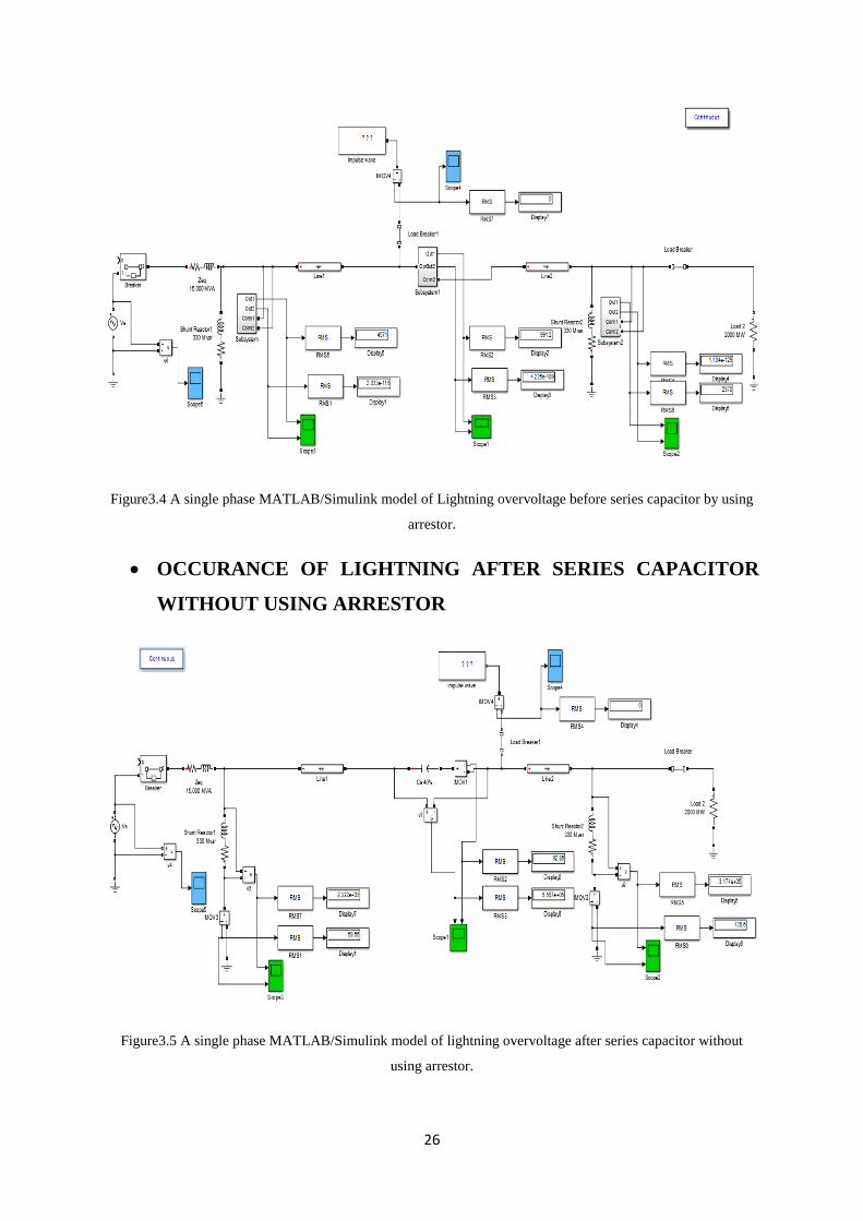
OCCURANCE OF LIGHTNING BEFORE SERIES CAPACITOR
WITHOUT ARRESTOR
In this case when lightning will fall before the series capacitor on the transmission line
there is no arrestor present in parallel to the shunt and series compensated device. All
lightning overvoltage will pass though the compensated devices attached across the system.
Figure3.3 A single phase MATLAB/Simulink model of lightning overvoltage before series capacitor without
using arrestor.
OCCURANCE OF LIGHTNING BEFORE SERIES CAPACITOR
BY USING ARRESTOR
In this case when the lightning will fall before the series capacitor, the arrestor installed in
parallel to the shunt and series compensation devices protect the system from the heavy
voltage develop across the system. When the lightning impulse will fall on the transmission
line, the system will produce a back flash to the receiving end and ground the large amount of
lightning voltage to the ground and save the system from heavy damage.
26
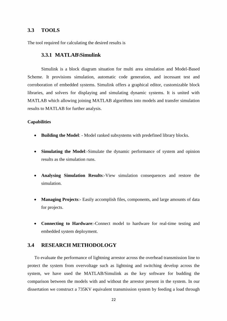
Figure3.4 A single phase MATLAB/Simulink model of Lightning overvoltage before series capacitor by using
arrestor.
OCCURANCE OF LIGHTNING AFTER SERIES CAPACITOR
WITHOUT USING ARRESTOR
Figure3.5 A single phase MATLAB/Simulink model of lightning overvoltage after series capacitor without
using arrestor.
27
In this case when lightning will fall after series capacitor on the transmission line there is
no arrestor present in parallel to the shunt and series compensated device. All lightning
overvoltage will pass though the compensated devices attached across the system.
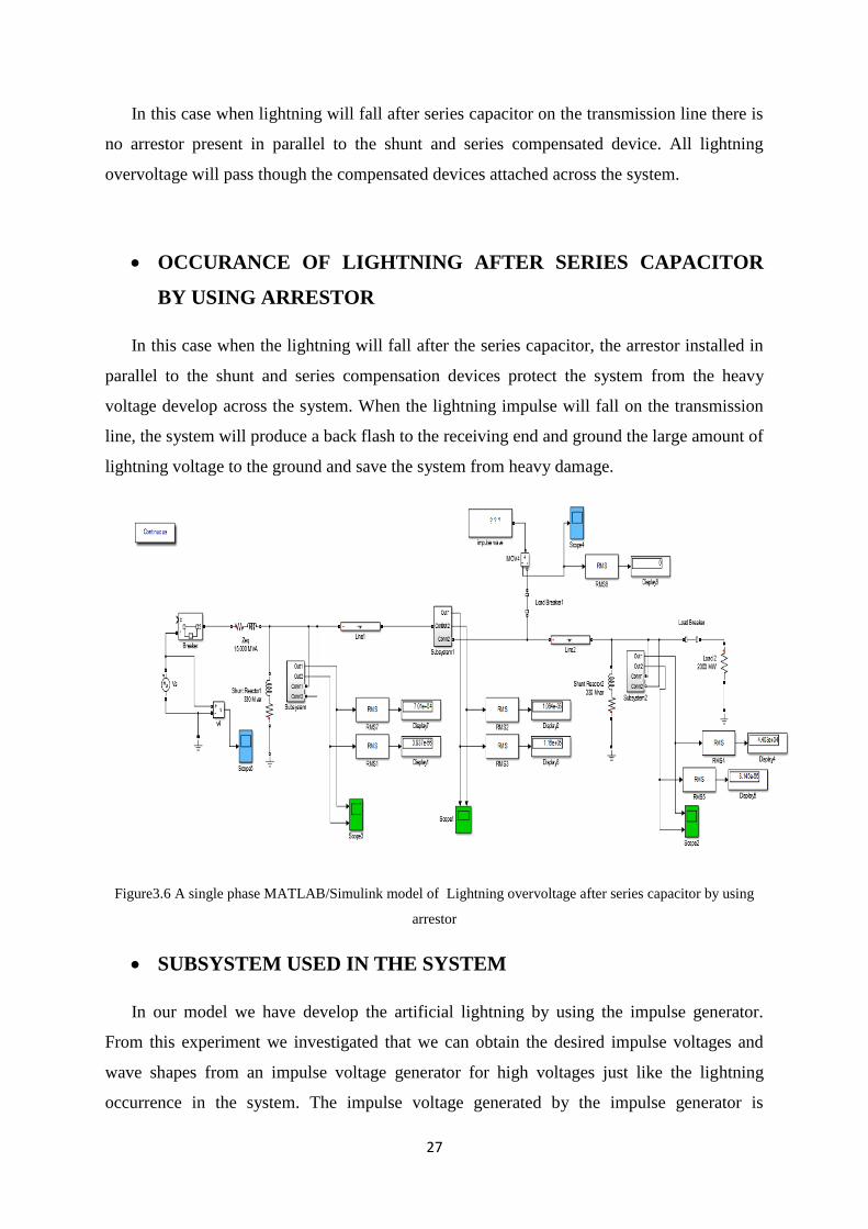
OCCURANCE OF LIGHTNING AFTER SERIES CAPACITOR
BY USING ARRESTOR
In this case when the lightning will fall after the series capacitor, the arrestor installed in
parallel to the shunt and series compensation devices protect the system from the heavy
voltage develop across the system. When the lightning impulse will fall on the transmission
line, the system will produce a back flash to the receiving end and ground the large amount of
lightning voltage to the ground and save the system from heavy damage.
Figure3.6 A single phase MATLAB/Simulink model of Lightning overvoltage after series capacitor by using
arrestor
SUBSYSTEM USED IN THE SYSTEM
In our model we have develop the artificial lightning by using the impulse generator.
From this experiment we investigated that we can obtain the desired impulse voltages and
wave shapes from an impulse voltage generator for high voltages just like the lightning
occurrence in the system. The impulse voltage generated by the impulse generator is

28
4.831* volts which act as external lightning source occurring in the system [1][12].
Impulse voltage generator can be developed by MATLAB Simulink with standard blocks
available in Simulink as shown in Fig. 7. The single-stage impulse voltage generator acting as
lightning source is simulated with the software. The stage sphere gaps were simulated by the
use of switches, as shown. In the case of multistage system, each of the stage capacitors was
given an initial charge voltage value, which is equal to 1/n of the total kV test voltage. The
values of front and tail resistors, as well as the stage capacitors, are the same as used in the
actual impulse generator. The impulse wave forms generated from MATLAB/Simulink
model with different front and tail resistor[11][12]
Figure3.7 Simulink model of impulse generator
29
CHAPTER 4
RESULTS AND DISCUSSION
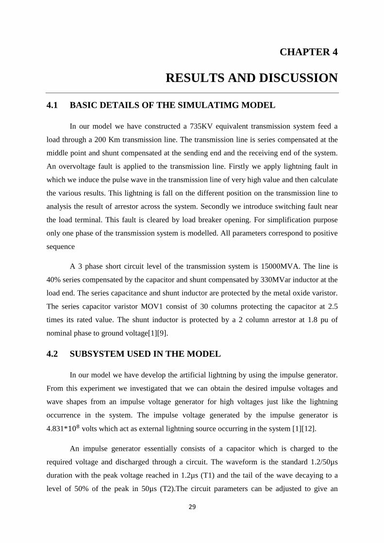
4.1 BASIC DETAILS OF THE SIMULATIMG MODEL
In our model we have constructed a 735KV equivalent transmission system feed a
load through a 200 Km transmission line. The transmission line is series compensated at the
middle point and shunt compensated at the sending end and the receiving end of the system.
An overvoltage fault is applied to the transmission line. Firstly we apply lightning fault in
which we induce the pulse wave in the transmission line of very high value and then calculate
the various results. This lightning is fall on the different position on the transmission line to
analysis the result of arrestor across the system. Secondly we introduce switching fault near
the load terminal. This fault is cleared by load breaker opening. For simplification purpose
only one phase of the transmission system is modelled. All parameters correspond to positive
sequence
A 3 phase short circuit level of the transmission system is 15000MVA. The line is
40% series compensated by the capacitor and shunt compensated by 330MVar inductor at the
load end. The series capacitance and shunt inductor are protected by the metal oxide varistor.
The series capacitor varistor MOV1 consist of 30 columns protecting the capacitor at 2.5
times its rated value. The shunt inductor is protected by a 2 column arrestor at 1.8 pu of
nominal phase to ground voltage[1][9].
4.2 SUBSYSTEM USED IN THE MODEL
In our model we have develop the artificial lightning by using the impulse generator.
From this experiment we investigated that we can obtain the desired impulse voltages and
wave shapes from an impulse voltage generator for high voltages just like the lightning
occurrence in the system. The impulse voltage generated by the impulse generator is
4.831* volts which act as external lightning source occurring in the system [1][12].
An impulse generator essentially consists of a capacitor which is charged to the
required voltage and discharged through a circuit. The waveform is the standard 1.2/50µs
duration with the peak voltage reached in 1.2µs (T1) and the tail of the wave decaying to a
level of 50% of the peak in 50µs (T2).The circuit parameters can be adjusted to give an

30
impulse voltage of the desired shape. Basic circuit of a single stage impulse generator where
the capacitor Cs is charged from a dc source until the spark gap G breaks down. The voltage
is then impressed upon the object under test of capacitance Cb. The wave shaping resistors
Rd and Re control the front and tail of the impulse voltage available across Cb respectively.
Overall, the wave shape is determined by the values of the generator capacitance (Cs) and the
load capacitance (Cb), and the wave control resistances Rd and Re[11][12].
v(t)=
(𝑒 𝑒 ) --------------4.1
Where
----------------------------------4.2
--------------------------------------------4.3
Figure4.1 Represent the Voltage Vs Time wave generated by impulse generator which act as lightning voltage
source
Figure4.2 Represent the Current Vs Time wave generated by impulse generator which act as lightning current
source

31
The graphical representation in figure4.1 and 4.2 are the voltage and current
waveform occur by the pulse generator. The RMS value of voltage is 4831 MV occurring in
the system which acts as lightning production in the system. These are just a pulse wave
produced in the system to make the system faulty due to overvoltage occur in the system just
like the occurrence of lightning.
4.3 SIMULATION CRITERIA
The simulation criteria are conducted by creating the model in the
MATLAB\Simulink. The variation in voltage and currents occur in the system which show us
the different simulations regarding the type of model used for evaluating the lightning
arrestors performance in the system. For comparing the simulations regarding the evaluation
of arrestor we develop two similar models, one by using arrestor and another without using
arrestor. From this we come to know about the performance of arrestor in the system.
4.3.1 SWITCHING OVERVOLTAGE
The increase in transmission voltage needs to fulfil the requirement of increase
transmission powers, switching surges have become the main factor for designing of
insulation for the transmission line. In the meantime the lightning overvoltage which is a
source of external overvoltage develops across the system comes as a secondary factor in the
transmission line protection.
In our dissertation we are comparing the two models of transmission line on which
switching overvoltage develops. First model is constructed by using the arrestor and second
without using arrestor. In these models when switching overvoltage occurs, we see the rate of
change of current and voltage develop across the system and the variation result carried out in
the system by using arrestor and without using arrestor.
4.3.1.1 SWITCHING OVERVOLTAGE ACROSS COMPENSATION
DEVICES
WITHOUT USING ARRESTOR
In this system when there is any switching operation when occur, there is no arrestor
present in the system. We have calculated the different values of RMS voltage and current in
the sending, midpoint and at the receiving end of the transmission line.

32
Table 4.1 switching overvoltage without using arrestor
RMS
Voltage at
sending
end ( )
RMS
Current at
sending
end ( )
RMS
Voltage at
midpoint
( )
RMS
Current at
midpoint
( )
RMS
Voltage at
receiving
end ( )
RMS
Current at
receiving
end ( )
Time frame
(T)
6.026𝑒 358.4 6.529𝑒 501.5 1.074𝑒 348.6 0.01
6.026𝑒 358.4 6.529𝑒 501.5 1.074𝑒 348.6 0.02
1.687𝑒 192.9 5.119𝑒 7775 8551 330.2 0.03
6.677𝑒 29.18 3.073𝑒 1.752𝑒 1.89𝑒 341.9 0.04
9.026𝑒 60.92 1.621𝑒 1.771𝑒 2.011𝑒 332.6 0.05
3.496𝑒 408.6 4.944𝑒 583.9 3.679𝑒 903.7 0.06
2.005𝑒 376.1 3.864𝑒 1456 1.159𝑒 920 0.07
3.486𝑒 350 2.463𝑒 1508 4.288𝑒 2227 0.08
3.171𝑒 401.5 3.986𝑒 1948 4.241𝑒 1700 0.09
3.014𝑒 322 1.461𝑒 2459 5.973𝑒 2270 0.10
Figure4.3 Voltage Vs Time and Current Vs Time waveform of the shunt reactor at the sending end of
transmission line, switching overvoltage without using arrestor
Figure4.4 Voltage Vs Time and Current Vs Time waveform of the series capacitor at the midpoint of
transmission line,switching overvoltage without using arrestor
33
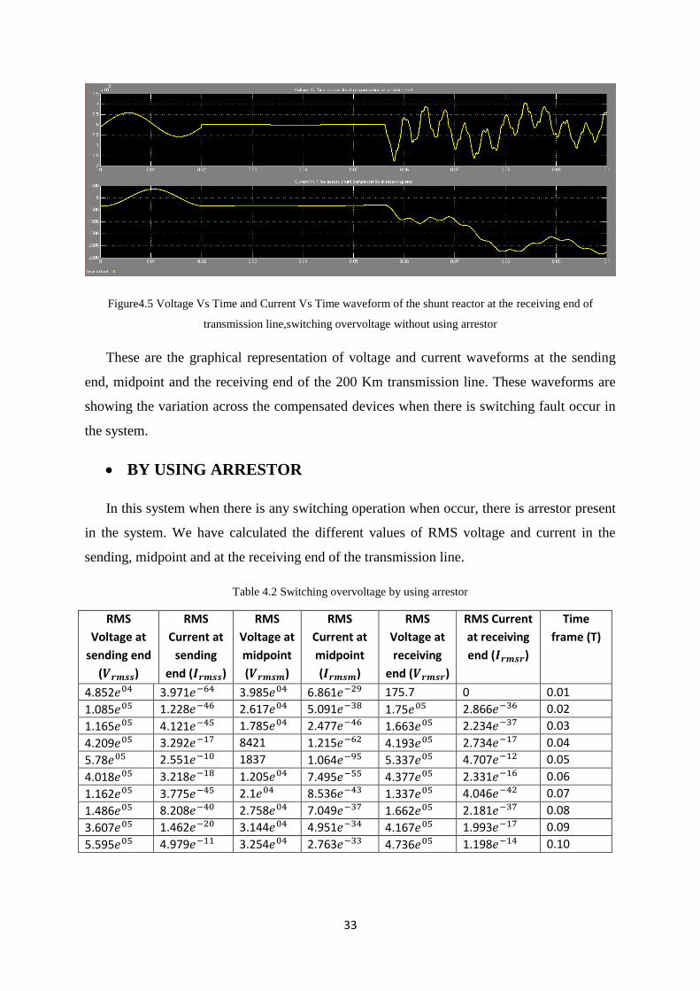
Figure4.5 Voltage Vs Time and Current Vs Time waveform of the shunt reactor at the receiving end of
transmission line,switching overvoltage without using arrestor
These are the graphical representation of voltage and current waveforms at the sending
end, midpoint and the receiving end of the 200 Km transmission line. These waveforms are
showing the variation across the compensated devices when there is switching fault occur in
the system.
BY USING ARRESTOR
In this system when there is any switching operation when occur, there is arrestor present
in the system. We have calculated the different values of RMS voltage and current in the
sending, midpoint and at the receiving end of the transmission line.
Table 4.2 Switching overvoltage by using arrestor
RMS
Voltage at
sending end
( )
RMS
Current at
sending
end ( )
RMS
Voltage at
midpoint
( )
RMS
Current at
midpoint
( )
RMS
Voltage at
receiving
end ( )
RMS Current
at receiving
end ( )
Time
frame (T)
4.852𝑒 3.971𝑒 3.985𝑒 6.861𝑒 175.7 0 0.01
1.085𝑒 1.228𝑒 2.617𝑒 5.091𝑒 1.75𝑒 2.866𝑒 0.02
1.165𝑒 4.121𝑒 1.785𝑒 2.477𝑒 1.663𝑒 2.234𝑒 0.03
4.209𝑒 3.292𝑒 8421 1.215𝑒 4.193𝑒 2.734𝑒 0.04
5.78𝑒 2.551𝑒 1837 1.064𝑒 5.337𝑒 4.707𝑒 0.05
4.018𝑒 3.218𝑒 1.205𝑒 7.495𝑒 4.377𝑒 2.331𝑒 0.06
1.162𝑒 3.775𝑒 2.1𝑒 8.536𝑒 1.337𝑒 4.046𝑒 0.07
1.486𝑒 8.208𝑒 2.758𝑒 7.049𝑒 1.662𝑒 2.181𝑒 0.08
3.607𝑒 1.462𝑒 3.144𝑒 4.951𝑒 4.167𝑒 1.993𝑒 0.09
5.595𝑒 4.979𝑒 3.254𝑒 2.763𝑒 4.736𝑒 1.198𝑒 0.10

34
Figure4.6 Voltage Vs Time and Current Vs Time waveform of the shunt reactor at the sending end of
transmission line, switching overvoltage by using arrestor
Figure4.7 Voltage Vs Time and Current Vs Time waveform of the series capacitor at the midpoint of
transmission line,switching overvoltage by using arrestor
Figure4.8 Voltage Vs Time and Current Vs Time waveform of the shunt reactor at the receivingend of
transmission line,switching overvoltage by using arrestor
35
These are the graphical representation of voltage and current waveforms at the
sending end, midpoint and the receiving end of the 200 Km transmission line. These
waveforms are showing the variation across the arrestor attached in parallel to the
compensated devices the voltage and current when there is switching fault occur in the
system.
4.3.2 LIGHTNING OVERVOLTAGE
Lighting can change huge damage to low voltage installation. These installations
include high rise buildings, communication lines and equipment’s and other similar facilities.
Lighting may travel on power lines and enter these installations through power lines. So we
have constructed a transmission line on which the lightning will fall. Just like the switching
case we have built the model by using surge arrestor and without using surge arrestor across
the transmission line. For more modification we have inserted the lightning which is
produced by impulse generator (subsystem) on the various positions on the transmission line.
For understanding about the effect of lightning occurrence in the system we are
considering two cases in which we are falling lightning at different position on the
transmission line. After falling the lightning on the transmission line we consider two cases
with and without arrestor to analysis the effect of lightning occurrence in the system.
4.3.2.1 OCCURANCE OF LIGHTNING BEFORE SERIES CAPACITOR
WITHOUT USING ARRESTOR
In this system when there is any lightning operation occur before series capacitor, there is
no arrestor present in the system. We have calculated the different values of RMS voltage and
current in the sending, midpoint and at the receiving end of the transmission line. When there
is no arrestor present in the system the voltage and current develop by the lightning will
passes through the compensated devices and damage the compensated system attached across
the system and make the system faulty.

36
Table 4.3 Overvoltage before series capacitor without using arrestor
RMS
Voltage at
sending
end ( )
RMS
Current at
sending
end ( )
RMS
Voltage at
midpoint
( )
RMS
Current at
midpoint
( )
RMS
Voltage at
receiving
end ( )
RMS
Current at
receiving
end ( )
Time frame
(T)
2.663𝑒 13.36 11.11 1477 4545 6.308 0.01
8195 8.514 15.95 432.1 5029 0.6098 0.02
5071 5.484 2.856 289.6 512.1 3.333 0.03
3229 4.081 3.444 723.8 66.07 3.716 0.04
1727 2.389 3.533 1081 118.6 3.629 0.05
1075 2.857 1.27 1298 2339 0.7514 0.06
1390 0.606 0.0435 1430 2183 1.544 0.07
4097 0.1562 0.1145 1394 4387 1.537 0.08
3788 2.118 1.614 1269 5609 2.029 0.09
4571 3.722 4.279 991.2 2369 2.514 0.10
Figure4.9 Voltage Vs Time and Current Vs Time waveform of the shunt reactor at the sending end of
transmission line,Lightning overvoltage before series capacitor without using arrestor
Figure4.10 Voltage Vs Time and Current Vs Time waveform of the series capacitor at the midpoint of
transmission line,Lightning overvoltage before series capacitor without using arrestor

37
Figure4.11 Voltage Vs Time and Current Vs Time waveform of the shunt reactor at the receiving end of
transmission line,Lightning overvoltage before series capacitor without using arrestor
These are the graphical representation of voltage and current waveforms at the sending
end, midpoint and the receiving end of the 200 Km transmission line. These waveforms are
showing the variation across the compensated devices the voltage and current when there is
lightning occur in the system before series capacitor attached to the system.
BY USING ARRESTOR
In this system when there is any lightning operation occur before series capacitor, there is
arrestor present in the system. We have calculated the different values of RMS voltage and
current in the sending, midpoint and at the receiving end of the transmission line.
Table 4.4 Lightning overvoltage before series capacitor by using arrestor
RMS
Voltage at
sending end
( )
RMS
Current at
sending
end ( )
RMS
Voltage at
midpoint
( )
RMS
Current at
midpoint
( )
RMS
Voltage at
receiving
end ( )
RMS
Current at
receiving
end ( )
Time frame
(T)
2.663 𝑒 3.804 𝑒 1477 1.911𝑒 1.536𝑒 4546 0.01
8191 9.367𝑒 432.1 3.968𝑒 2.435𝑒 5030 0.02
5071 3.667𝑒 289.6 8.02𝑒 0 512.2 0.03
3230 5.843𝑒 723.8 6.292𝑒 0 66.03 0.04
1726 1.429𝑒 1081 3.217𝑒 0 118.7 0.05
1075 7.483𝑒 1298 2.995𝑒 5.695𝑒 2338 0.06
1391 3.006𝑒 1430 3.783𝑒 1.826𝑒 2183 0.07
4098 6621𝑒 1394 1.07𝑒 2.609𝑒 4387 0.08
3785 1.626𝑒 1269 9.775𝑒 5.771𝑒 5611 0.09
4571 2.033𝑒 9912 4.225𝑒 1.104𝑒 2370 0.10

38
Figure4.12 Voltage Vs Time and Current Vs Time waveform of the shunt reactor at the sending end of
transmission line,Lightning overvoltage before series capacitor by using arrestor
Figure4.13 Voltage Vs Time and Current Vs Time waveform of the series capacitor at the midpoint of
transmission line,Lightning overvoltage before series capacitor by using arrestor
Figure4.14 Voltage Vs Time and Current Vs Time waveform of the shunt reactor at the receiving end of
transmission line,Lightning overvoltage before series capacitor by using arrestor
These are the graphical representation of voltage and current waveforms at the
sending end, midpoint and the receiving end of the 200 Km transmission line. These
39
waveforms are showing the variation across the arrestor attached in parallel to the
compensated devices when there is lightning occur in the system before series capacitor
attached to the system.
4.3.2.2 OCCURANCE OF LIGHTNING AFTER SERIES CAPACITOR
WITHOUT USING ARRESTOR
In this system when there is any lightning operation occur after series capacitor, there is
no arrestor present in the system. We have calculated the different values of RMS voltage and
current in the sending, midpoint and at the receiving end of the transmission line.
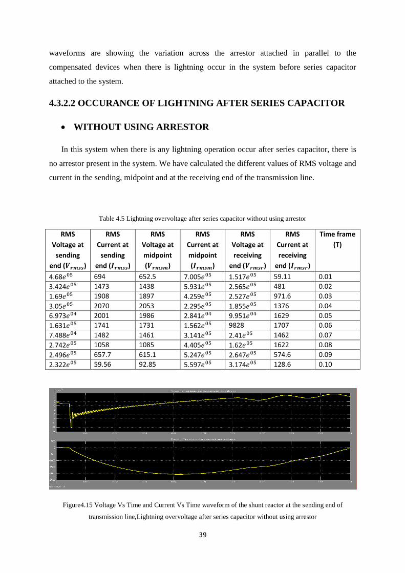
Table 4.5 Lightning overvoltage after series capacitor without using arrestor
RMS
Voltage at
sending
end ( )
RMS
Current at
sending
end ( )
RMS
Voltage at
midpoint
( )
RMS
Current at
midpoint
( )
RMS
Voltage at
receiving
end ( )
RMS
Current at
receiving
end ( )
Time frame
(T)
4.68𝑒 694 652.5 7.005𝑒 1.517𝑒 59.11 0.01
3.424𝑒 1473 1438 5.931𝑒 2.565𝑒 481 0.02
1.69𝑒 1908 1897 4.259𝑒 2.527𝑒 971.6 0.03
3.05𝑒 2070 2053 2.295𝑒 1.855𝑒 1376 0.04
6.973𝑒 2001 1986 2.841𝑒 9.951𝑒 1629 0.05
1.631𝑒 1741 1731 1.562𝑒 9828 1707 0.06
7.488𝑒 1482 1461 3.141𝑒 2.41𝑒 1462 0.07
2.742𝑒 1058 1085 4.405𝑒 1.62𝑒 1622 0.08
2.496𝑒 657.7 615.1 5.247𝑒 2.647𝑒 574.6 0.09
2.322𝑒 59.56 92.85 5.597𝑒 3.174𝑒 128.6 0.10
Figure4.15 Voltage Vs Time and Current Vs Time waveform of the shunt reactor at the sending end of
transmission line,Lightning overvoltage after series capacitor without using arrestor

40
Figure4.16 Voltage Vs Time and Current Vs Time waveform of the series capacitor at the midpoint of
transmission line,Lightning overvoltage after series capacitor without using arrestor
Figure4.17 Voltage Vs Time and Current Vs Time waveform of the shunt reactor at the receiving end of
transmission line,Lightning overvoltage after series capacitor without using arrestor
These are the graphical representation of voltage and current waveforms at the sending
end, midpoint and the receiving end of the 200 Km transmission line. These waveforms are
showing the variation across the compensated devices when there is lightning occur in the
system after series capacitor attached to the system
BY USING ARRESTOR
In this system when there is any lightning operation occur before series capacitor, there is
arrestor present in the system. We have calculated the different values of RMS voltage and
current in the sending, midpoint and at the receiving end of the transmission line.
41
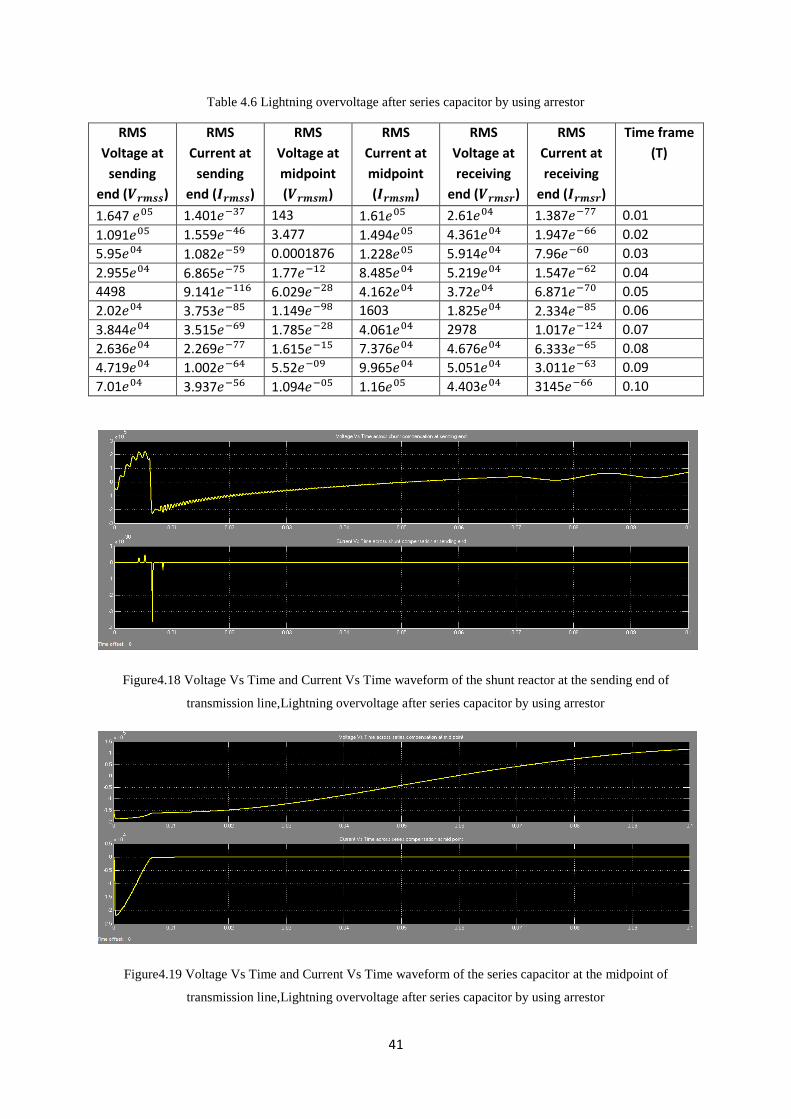
Table 4.6 Lightning overvoltage after series capacitor by using arrestor
RMS
Voltage at
sending
end ( )
RMS
Current at
sending
end ( )
RMS
Voltage at
midpoint
( )
RMS
Current at
midpoint
( )
RMS
Voltage at
receiving
end ( )
RMS
Current at
receiving
end ( )
Time frame
(T)
1.647 𝑒 1.401𝑒 143 1.61𝑒 2.61𝑒 1.387𝑒 0.01
1.091𝑒 1.559𝑒 3.477 1.494𝑒 4.361𝑒 1.947𝑒 0.02
5.95𝑒 1.082𝑒 0.0001876 1.228𝑒 5.914𝑒 7.96𝑒 0.03
2.955𝑒 6.865𝑒 1.77𝑒 8.485𝑒 5.219𝑒 1.547𝑒 0.04
4498 9.141𝑒 6.029𝑒 4.162𝑒 3.72𝑒 6.871𝑒 0.05
2.02𝑒 3.753𝑒 1.149𝑒 1603 1.825𝑒 2.334𝑒 0.06
3.844𝑒 3.515𝑒 1.785𝑒 4.061𝑒 2978 1.017𝑒 0.07
2.636𝑒 2.269𝑒 1.615𝑒 7.376𝑒 4.676𝑒 6.333𝑒 0.08
4.719𝑒 1.002𝑒 5.52𝑒 9.965𝑒 5.051𝑒 3.011𝑒 0.09
7.01𝑒 3.937𝑒 1.094𝑒 1.16𝑒 4.403𝑒 3145𝑒 0.10
Figure4.18 Voltage Vs Time and Current Vs Time waveform of the shunt reactor at the sending end of
transmission line,Lightning overvoltage after series capacitor by using arrestor
Figure4.19 Voltage Vs Time and Current Vs Time waveform of the series capacitor at the midpoint of
transmission line,Lightning overvoltage after series capacitor by using arrestor

42
Figure4.20 Voltage Vs Time and Current Vs Time waveform of the shunt reactor at the receiving end of
transmission line,Lightning overvoltage after series capacitor by using arrestor
These are the graphical representation of voltage and current waveforms at the
sending end, midpoint and the receiving end of the 200 Km transmission line. These
waveforms are showing the variation across the arrestor attached in parallel to the
compensated devices when there is lightning occur in the system after series capacitor
attached to the system
4.4 SIMULATION RESULTS
Case 1- Switching overvoltage across compensation devices
Table4.7 Comparison between Switching overvoltage with arrestor and without arrestor model
S.No Without Arrestor With Arrestor
1
Sending end Voltage Vs Time and Current Vs
Time waveforms
Average RMS Voltage ( )= 1.983 𝑒 V
Average RMS Current ( )=285.8 A
Sending end Voltage Vs Time and Current Vs
Time waveforms
Average RMS Voltage ( )= 92020 V
Average RMS Current ( )=3.0489 𝑒 A
43
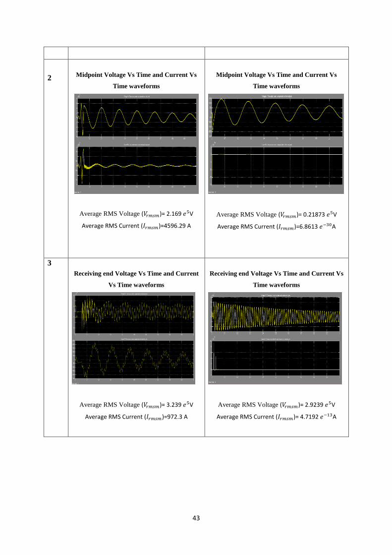
2
Midpoint Voltage Vs Time and Current Vs
Time waveforms
Average RMS Voltage ( )= 2.169 𝑒 V
Average RMS Current ( )=4596.29 A
Midpoint Voltage Vs Time and Current Vs
Time waveforms
Average RMS Voltage ( )= 0.21873 𝑒 V
Average RMS Current ( )=6.8613 𝑒 A
3
Receiving end Voltage Vs Time and Current
Vs Time waveforms
Average RMS Voltage ( )= 3.239 𝑒 V
Average RMS Current ( )=972.3 A
Receiving end Voltage Vs Time and Current Vs
Time waveforms
Average RMS Voltage ( )= 2.9239 𝑒 V
Average RMS Current ( )= 4.7192 𝑒 A

44
Case 2- Occurrence of lightning before series capacitor
Table4.8 Comparison between lightning overvoltage before series capacitor with arrestor and without arrestor
model
S.No Without Arrestor With Arrestor
1
Sending end Voltage Vs Time and Current Vs
Time waveforms
Average RMS Voltage ( )= 3314.56V
Average RMS Current ( )=4.568 A
Sending end Voltage Vs Time and Current Vs
Time waveforms
Average RMS Voltage ( )= 5976.8 V
Average RMS Current ( )=3.804 𝑒 A
2
Midpoint Voltage Vs Time and Current Vs
Time waveforms
Average RMS Voltage ( )= 4.4214 V
Average RMS Current ( )=1038.57 A
Midpoint Voltage Vs Time and Current Vs
Time waveforms
Average RMS Voltage ( )= 1930.65V
Average RMS Current ( )=1.911 𝑒 A
3
Receiving end Voltage Vs Time and Current
Vs Time waveforms
Average RMS Voltage ( )= 2715.77V
Average RMS Current ( )=2.5971 A
Receiving end Voltage Vs Time and Current Vs
Time waveforms
Average RMS Voltage ( )= 5.771 𝑒 V
Average RMS Current ( )= 2716.193A

45
Case 3- Occurrence of lightning before series capacitor
Table4.9 Comparison between lightning overvoltage after series capacitor with arrestor and without arrestor
model
S.No Without Arrestor With Arrestor
1
Sending end Voltage Vs Time and Current Vs
Time waveforms
Average RMS Voltage ( )= 2.3481 𝑒 V
Average RMS Current ( )=2863.556A
Sending end Voltage Vs Time and Current Vs
Time waveforms
Average RMS Voltage ( )= 20229 V
Average RMS Current ( )=9.141 𝑒 A
2
Midpoint Voltage Vs Time and Current Vs
Time waveforms
Average RMS Voltage ( )= 1474.945V
Average RMS Current ( )=847261 A
Midpoint Voltage Vs Time and Current Vs
Time waveforms
Average RMS Voltage ( )= 14.6477V
Average RMS Current ( )=85068.70A
3
Receiving end Voltage Vs Time and Current
Vs Time waveforms
Average RMS Voltage ( )= 253393.8V
Average RMS Current ( )=807.691 A
Receiving end Voltage Vs Time and Current Vs
Time waveforms
Average RMS Voltage ( )= 38076.8V
Average RMS Current ( )= 7.978 𝑒 A
46
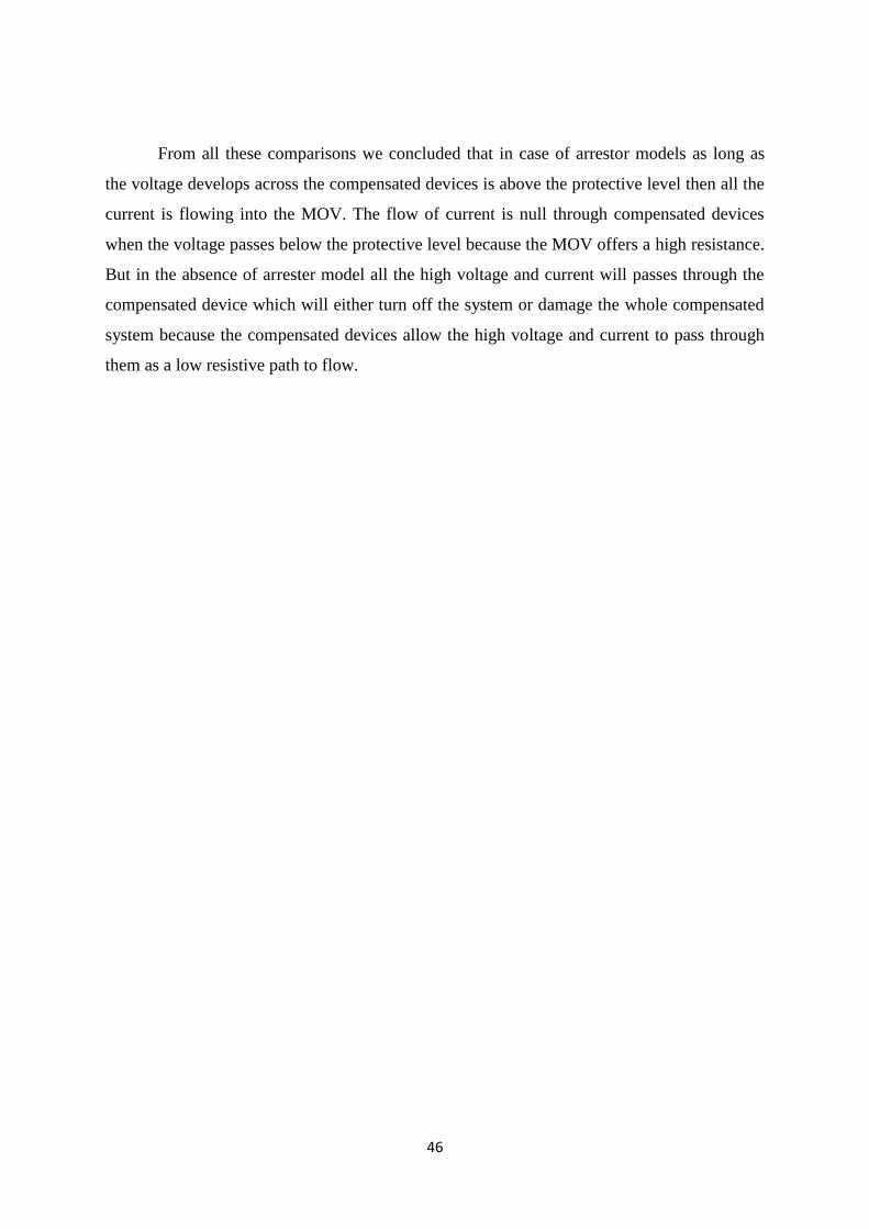
From all these comparisons we concluded that in case of arrestor models as long as
the voltage develops across the compensated devices is above the protective level then all the
current is flowing into the MOV. The flow of current is null through compensated devices
when the voltage passes below the protective level because the MOV offers a high resistance.
But in the absence of arrester model all the high voltage and current will passes through the
compensated device which will either turn off the system or damage the whole compensated
system because the compensated devices allow the high voltage and current to pass through
them as a low resistive path to flow.

47
CHAPTER 5
CONCLUSION AND FUTURE SCOPE
5.1 CONCLUSION
In our dissertation, we have design the model of transmission line on which we
evaluated the performance of lightning arrestor installed in the system. All the simulation is
carried out in MATLAB/Simulink. We have designed a transmission model in which we have
analysed the switching overvoltage occurrence with or without the help of surge arrestor and
compared their results and evaluated the performance of arrestor across the line.
We have also analysed the system when lightning overvoltage strikes the system. For
simulation of lightning, we used a transfer impulse function block as impulse generator which
induces a large voltage across the transmission line just like the occurrences of lightning in
the nature (in the Simulink). All the simulations were carried out by inserting the transfer
function block at different points on the transmission line and then comparisons were made.
Simulation results are compared by using arrestor or without using arrestor model. In the last
we concluded that it is preferable to use arrestor across the line to protect the compensated
devices across the system because the arrestor protective devices operate immediately in
order to remove the heavy overvoltage to pass through the compensated devices. The flow of
current is null through compensated devices when the voltage passes below the protective
level because the arrestor offers a high resistance.
5.2 FUTURE SCOPE
By considering the various factors corresponding to the lightning and switching
overvoltage’s we can use this extra energy for harvesting purposes. This is a very difficult
task but not impossible. As we come to know the various parameters on which lightning
depends we can develop a control system which can control this extra energy source for
harvesting purpose.

48
REFERENCES
[1] Bui-Van Q., E. Portales, D. McNabb, and V. Gajardo, “Transient Performance of 500-kV
Equipment for the Chilean Series-Compensated Transmission System,” Proceedings of the
international Conference on Power System Transients (IPST’03), pp. 1-6, October 2008
[2] Chanaka M., KusumShanthi, RanjitPerera “Modeling of Power Transmission Lines for
Lightning Back Flashover Analysis (A Case Study: 220kV Biyagama-Kotmale Transmission
Line)” 2011 IEEE 6th
International Conference on Industrial and Information Systems, ICIIS
2011, Aug. 16-19, 2011, Sri Lanka
[3] Christodoulou1 C.A., G. Perantzakis, G.E. Spanakis, P. Karampelas”Evaluation of
lightning performance of transmission lines protected by metal oxide surge arrestors using
artificial intelligence techniques”2006, Journal of Energy Systems The final publication is
available at www.springerlink.com
[4] Dingxie Gu, Dai Min, He Huiwen, High Voltage Institute China State Grid Electric
Power Research Institute Wuhan, China “Lightning Protection of 1000 kV AC Power
Transmission Lines and Substations” 2011 IEEE, 7th
Asia-Pacific International Conference
on Lightning, November 1-4, 2011, Chengdu, China
[5] Ekonomou L., I.F. Gonos, D.P. Iracleous, I.A. Stathopulos”Application of artificial neural
network methods for the lightning performance evaluation of Hellenic high voltage
transmission lines” Electric Power Systems Research 77 (2007) National Technical
University of Athens, School of Electrical and Computer Engineering, High Voltage
Laboratory, 9 IroonPolitechniou St., Zografou, GR 157 80 Athens, Greece
[6] Ekonomou L, P Karampelas, V Vita and G E Chatzarakis “Evaluation of the probability
of arrestor failure in a high-voltage transmission line using a Q learning artificial neural
network model”© 2011 IOP Publishing Ltd Printed in the UK & the USA 27
49
[7] Eguzo C.V, E.I Igweonu and B.J Robert “SELECTION CRITERIA FOR LIGHTNING
ARRESTOR SYSTEMS IN NIGERIA” International Journal of Advancements in Research
& Technology, Volume 2, Issue4, April-2013, Electrical Electronics Engineering Department
AkanuIbiam Federal Polytechnic, Unwana
[8] Gupta B.R. “power system analysis and design” book,first edition 2005
[9] Henschel S., L. Kischner, and M. C. Lima, “Transient Recovery Voltage at Series
Compensated Transmission Lines in Piauí, Brazil,” Proceedings of the International
Conference on Power System Transients (IPST’05), pp. 1-6, June 2005
[10] Johar Dalinai, TitikKhawa Abdul Rahman, Ismail Musirin, Member, IEEE”Artificial
Neural Network Based Technique for Lightning Prediction”The 5th
Student Conference on
Research and Development –SCO 11-12 December 2007, Malaysia
[11] Jayaraju M., B. Prabhakar. Generation of unidirectional and bidirectional oscillatory
switching impulse voltages.in: Proceeding of the 9th
International Symposium on High
voltage Engineering, Graz Technical University, Austria, 1995
[12] Kannan S.,M.Tech,N.Rao.Generator loading limits for impulse testing low inductance
windings, in: Proceeding of the Institution of Electrical Engineers, 1957,122(5): 535-538
[13] Nekoubin Abdolamir “Simulation of series compensated transmission line protected
with Mov” World Academy of Science, Engineering and Technology, Vol:5 2011-10-28,
Electrical Engineering Department, Islamic Azard University Najaf Abad Branch,
International Scholarly and Scientific Research & Innovation 5(10)2011.
[14] Omidiora M.A.,”PERFORMANCE ANALYSIS OF LIGHTNING OVERVOLTAGE
ON MEDIUM VOLTAGE DISTRIBUTION LINE EQUIPPED WITH COVERED
CONDUCTORS”, 2009, 2nd
international conference on adaptive sciences and technologies.

50
[15] Rodriguez-Sanabria D., Student Member, IEEE, C. Ramos-Robles, UPRM Graduate
Student, L. Orama- Exclusa, Member, IEEE”Lightning and Lightning Arrestor Simulation in
Electrical Power Distribution Systems”
[16] Ray Subir “electrical power system concepts, theory and practice” book, PHI Learning
private Limited 2012
[17] TarilanyoAfa John”Selection of Lightning Arrestor in the Niger Delta Environment”
International Journal of Innovation and Applied Studies ISSN 2028-9324 Vol. 3 No. 1 May
2013, Department of Electrical Engineering, Niger Delta University, PMB 71 Wilberforce
Island, Bayelsa state, Nigeria
[18] Vladimir A. Rakov”Lightning Discharge and Fundamentals of Lightning Protection”
Journal of Lightning Research, 2012,Department of Electrical & Computer Engineering,
University of Florida, Gainesville, FL, USA
[19] Wang Young,”SIMULATION OF LINE SURGE ARRESTOR FOR LIGHTNING
PROTECTION IN 10KV TRANSMISSION LINE”,Electricity distribution. 2008 CICED
2008, China International Conference,10-13 dec 2008
[20] Zhang Xuewei, Lin Dong, Jinliang He*, Shuiming Chen and RongZeng “Study on the
Effectiveness of Single Lightning Rods by a Fractal Approach” Lightning Research, 2009
State Key Lab of Power Systems, Department of Electrical Engineering, Tsinghua
University, Beijing 100084, China
51
APPENDIX
GLOSSARY OF TERMS
1. VOLTAGE SURGE: Any sudden excessive rise in the voltage that may be
dangerous to the electrical equipment’s of an installation is known as voltage surge.
2. LIGHTNING: Lightning is a huge spark which is due to the electrical discharge
taking place between the clouds, within the same cloud and between the cloud and
ground.
3. A STROKE LIGHTNING: A stroke lightning is characterised by the comparatively
long time to produce discharge. It strikes the highest and most sharply pointed object
in the neighbourhood.
4. B STROKE LIGHTNING: B stroke lightning is characterised by its rapidity. It
ignores the tall objects and reaches the ground in the random manner. B stroke is most
dangerous lightning stroke.
5. EARTHING SCREEN: Earthing screen consists of a network of copper conductors,
earthed at least on two points, over all the electrical equipment in the substation.
6. EARTH WIRE: An earth wire is a form of lightning protection using a conductor or
conductors, well-grounded at regular intervals, preferable at each support and attached
from support to support above the transmission line.
7. LIGHTNING ARRESTOR: Lightning arrestor limits the duration and amplitude of
the follow current.
8. SURGE ABSORBER: Surge absorber reduces the steepness of the wave front of a
particular surge.

52
ABBREVIATIONS
LFC : LOAD FREQUENCY CONTROL
MATLAB : MATRIX LABORATORY
PI : PROPORTIONAL-INTEGRAL
PID : PROPORTIONAL-INTEGRAL-DERIVATIVE
AC : ALTERNATING CURRENT
AGC : AUTOMATIC GENERATION CONTROL
ACE : AREA CONTROL ERROR
HVDC : HIGH VOLTAGE DIRECT CURRENT
EHVAC : EXTRA HIGH VOLTAGE ALTERNATING CURRENT
HIL : HARDWARE-IN-LOOP
SSE : STEADY STATE ERROR
MOV : METAL OXIDE VARISTOR
TSR : TOTAL SURGE REACTOR
ANN : ARTIFICIAL NEURAL NETWORK