evaluation of geophysical & borehole video logs ...fluid-resistivity log shows a consistent...
TRANSCRIPT
! SDMS DocID 2184351
EVALUATION OF GEOPHYSICAL
AND BOREHOLE VIDEO LOGS
AT THE LEHIGH ELECTRIC SUPERFUND SITE,
LACKAWANNA COUNTY, PENNSYLVANIA
U.S. GEOLOGICAL SURVEY Administrative Report
Prepared for the
U.S. ENVIRONMENTAL PROTECTION AGENCY
AR300030
EVALUATION OF GEOPHYSICAL
AND BOREHOLE VIDEO LOGS
AT THE LEHIGH ELECTRIC SUPERFUND SITE,
LACKAWANNA COUNTY, PENNSYLVANIA
by Randall W. Conger
U.S. GEOLOGICAL SURVEY Administrative Report
Prepared for the
U.S. ENVIRONMENTAL PROTECTION AGENCY
Lemoyne, Pennsylvania 1998
AR300031
INTRODUCTION
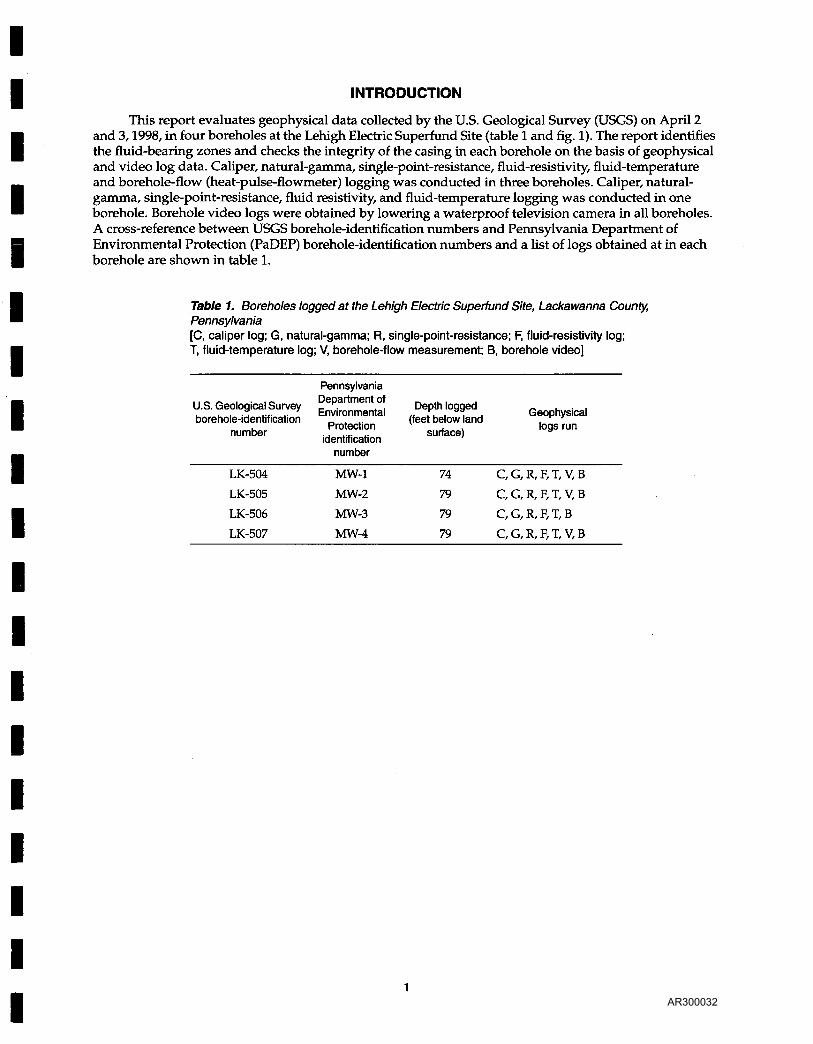
This report evaluates geophysical data collected by the U.S. Geological Survey (USGS) on April 2 and 3,1998, in four boreholes at the Lehigh Electric Superfund Site (table 1 and fig. 1). The report identifies the fluid-bearing zones and checks the integrity of the casing in each borehole on the basis of geophysical and video log data. Caliper, natural-gamma, single-point-resistance, fluid-resistivity, fluid-temperature and borehole-flow (heat-pulse-flowmeter) logging was conducted in three boreholes. Caliper, natural-gamma, single-point-resistance, fluid resistivity, and fluid-temperature logging was conducted in one borehole. Borehole video logs were obtained by lowering a waterproof television camera in all boreholes. A cross-reference between USGS borehole-identification numbers and Pennsylvania Department of Environmental Protection (PaDEP) borehole-identification numbers and a list of logs obtained at in each borehole are shown in table 1.
Table 1. Boreholes logged at the Lehigh Electric Superfund Site, Lackawanna County, Pennsylvania [C, caliper log; G, natural-gamma; R, single-point-resistance; F, fluid-resistivity log; T, fluid-temperature log; V, borehole-flow measurement; B, borehole video]
U.S. Geological Survey borehole-identification
number
Pennsylvania Department of Environmental
Protection identification
number
Depth logged (feet below land
surface)
Geophysical logs run
LK-504
LK-505
LK-506
LK-507
MW-1
MW-2
MW-3
MW-4
74
79
79
79
C, G, R, F, T, V, B
C, G, R, F, T, V, B
C, G, R, F, T, B
C, G, R, F, T, V, B
1 AR300032

BOREHOLE GEOPHYSICAL LOGS
Caliper logs provide a continuous record of average borehole diameter, which is related to fractures, lithology, and drilling technique. Caliper logs are used to help correlate lithostratigraphy, identify fractures and possible fluid-bearing openings, and qualitatively correct other geophysical logs for changes in borehole diameter. Correlation of caliper logs with fluid-resistivity and fluid-temperature logs is used to identify fractures and fluid-producing and fluid-receiving zones and to measure fluid velocity.
Natural-gamma logs, also called gamma-ray logs, record the natural-gamma radiation emitted from rocks penetrated by the borehole. Gamma radiation can be measured through casing, but the gamma response is dampened. Uranium-238 and thorium-232 and their decay products and potassium-40 are the most common emitters of natural-gamma radiation. These radioactive elements may be concentrated in clay by adsorption, precipitation, and ion exchange; accordingly, fine-grained sediments (siltstone units) usually emit more gamma radiation than do quartz-sand rocks (sandstone). Natural-gamma logs are used to correlate lithostratigraphy.
Single-point-resistance logs record the electrical resistance between the borehole and an electrical ground at land surface. In general, resistance increases with grain size and decreases with borehole diameter, density of water-bearing fractures, and increasing dissolved-solids concentration of borehole fluid. A fluid-filled borehole is required for single-point-resistance logs, and they are obtained only for the saturated part of the formation below the casing. Single-point-resistance logs are used to correlate lithostratigraphy and may help to identify the location of water-bearing zones. They also show the depth of steel casing.
Fluid-resistivity logs measure the electrical resistance of fluid in the borehole. Resistivity is the reciprocal of fluid conductivity, and fluid-resistivity logs reflect changes in the dissolved-solids concentration of the borehole fluid. Fluid-resistivity logs are used to identify fluid-producing and fluid-receiving zones and to determine intervals of vertical borehole flow. Fluid-producing and fluid-receiving zones usually are identified by sharp changes in resistivity, and intervals of borehole flow are identified by a low resistivity gradient between fluid-producing and fluid-receiving zones. A fluid-filled borehole is required for fluid-resistivity logs, and they are obtained only for the saturated part of the formation below the casing.
Fluid-temperature logs provide a continuous record of the temperature of the fluid in the borehole. Temperature logs are used to identify fluid-producing and fluid-receiving zones and to determine intervals of vertical borehole flow. Intervals of vertical borehole flow are identified by little or no temperature gradient. A fluid-filled borehole is required for fluid-temperature logs, and they are obtained only for the saturated part of the formation below the casing.
The direction and rate of borehole-fluid movement was determined by the use of a heat-pulse flowmeter. The heat-pulse flowmeter operates by heating a small sheet of water between two sensitive thermistors (heat sensors). A measurement of direction and rate is computed when a peak temperature is recorded by one of the thermistors. The range of flow measurement is about 0.01-1.0 gal/min (gallons per minute) in a 2- to 8-in.(inch)-diameter borehole.
2 AR300033
The heat-pulse flowmeter was used under nonpumping conditions. Some heat-pulse-flowmeter measurements may be influenced by a poor seal integrity between the borehole and heat-pulse flowmeter. An incomplete seal between the borehole and the flowmeter can cause some water to bypass the flowmeter, resulting in measurements of flow that are less than the actual rate. Although the heat-pulse flowmeter is a calibrated probe, the data are primarily used as a relative indicator to identify fluid-producing and fluid-receiving zones.
Borehole television logging, also known as video logging, was conducted by lowering a waterproof camera down the borehole and recording the image on video tape. The depth indicated on the video log may not correspond exactly to the geophysical logs because of some minor slippage of the television cable.
3 AR300034

ANALYSIS OF BOREHOLE GEOPHYSICAL LOGS
The location of boreholes logged are shown on figure 1.
75° 44' 45" 75° 44' 20"
41° 21' 35"
41° 21' 15"
Base from U.S. Geological Survey Avoca 1:24,000,1980
0 0.5 MILES
0.5 KILOMETERS
EXPLANATION
STUDY AREA
> LK-506 WELL AND IDENTIFICATION
NUMBER
LOCATION OF MAPPED AREA
Figure 1. Location of boreholes logged on the Lehigh Electric Superfund Site, Lackawanna County, Pennsylvania.
PENNSYLVANIA
4
AR300035
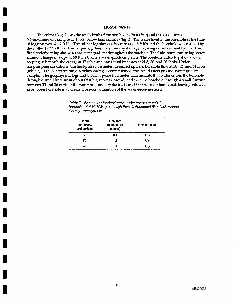
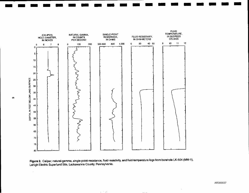
LK-504 (MW-1)
The caliper log shows the total depth of the borehole is 74 ft (feet) and it is cased with 6.5-in.-diameter casing to 17 ft bis (below land surface) (fig. 2). The water level in the borehole at the time of logging was 32.42 ft bis. The caliper log shows a fracture at 21.5 ft bis and the borehole was reamed by the driller to 22.5 ft bis. The caliper log does not show any damage in casing or broken weld joints. The fluid-resistivity log shows a consistent gradient throughout the borehole. The fluid-temperature log shows a minor change in slope at 68 ft bis that is a water-producing zone. The borehole video log shows water seeping in beneath the casing at 17 ft bis and horizontal fractures at 21.5,26, and 28 ft bis. Under nonpumping conditions, the heat-pulse flowmeter measured upward borehole flow at 38,52, and 64 ft bis (table 2). If the water seeping in below casing is contaminated, this could affect ground-water-quality samples. The geophysical logs and the heat-pulse-flowmeter data indicate that water enters the borehole through a small fracture at about 68 ft bis, moves upward, and exits the borehole through a small fracture between 33 and 36 ft bis. If the water produced by the fracture at 68 ft bis is contaminated, leaving this well as an open borehole may create cross-contamination of the water-receiving zone.
Table 2. Summary of heat-pulse-flowmeter measurements for borehole LK-504 (MW-1) at Lehigh Electric Superfund Site, Lackawanna County, Pennsylvania
Depth Flow rate (feet below (gallons per Flow direction
land surface) minute)
38 or u;
52 .1 Up
64 .1 Up
5 AR300036
(CALIPER) HOLE DIAMETER,
IN INCHES
NATURAL GAMMA, IN COUNTS
PER SECOND
I 100 200
SINGLE-POINT RESISTANCE,
IN OHMS
500 600 800 1,000
FLUID RESISTIVITY, IN OHM-METERS
) 20 40 50
FLUID TEMPERATURE,
IN DEGREES CELSIUS
10 11
D-
Figure 2. Caliper, natural-gamma, single-point-resistance, fluid-resistivity, and fluid-temperature logs from borehole LK-504 (MW-1), Lehigh Electric Superfund Site, Lackawanna County, Pennsylvania.
AR300037

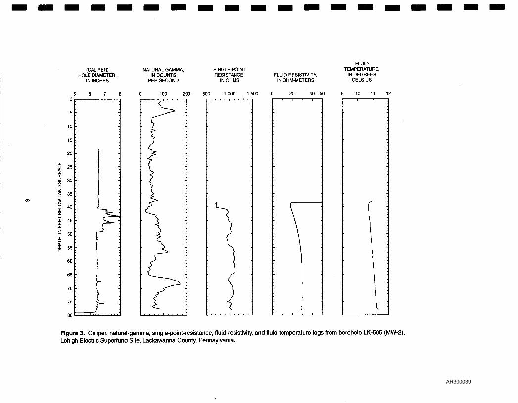
LK-5Q5 (MW-2)
The caliper log shows the total depth of the borehole is 79 ft and it is cased with 6.5-in.-diameter casing to 40 ft bis (fig. 3). The water level in the borehole at the time of logging was 37.99 ft bis. The caliper log shows fractures at 43, 46, 67, and 76 ft bis and the borehole was reamed by the driller to 49 ft bis. The caliper log does not show any damage in casing or broken weld joints. The fluid-resistivity and fluid-temperature logs show no sudden changes in slope. Under nonpumping conditions, the heat-pulse-flowmeter measurements indicated upward borehole flow at 51, 60, and 70 ft bis (table 3). The borehole video log shows horizontal fractures at 43,45,48,51, 67, 69, 75, and 76 ft bis and a vertical fracture at 71 ft bis. The geophysical logs and the heat-pulse-flowmeter data indicate water enters the borehole through the fractures at 76 ft bis, moves upward, and exits the borehole through fractures at 41-49 ft bis. If the water produced by the fractures at 76 ft bis is contaminated, leaving this well as an open borehole will create cross-contamination of the water-receiving zone.
Table 3. Summary of heat-pulse-flowmeter measurements for borehole LK-505 (MW-2) at Lehigh Electric Superfund Site, Lackawanna County, Pennsylvania
Depth Flow rate (feet below (gallons per Flow direction
land surface) minute)
51 020 Up
60 .15 Up
70 .18 Up
7 AR300038
(CALIPER) HOLE DIAMETER,
IN INCHES
NATURAL GAMMA, IN COUNTS
PER SECOND
SINGLE-POINT RESISTANCE,
IN OHMS FLUID RESISTIVITY,
IN OHM-METERS
FLUID TEMPERATURE,
IN DEGREES CELSIUS
100 200 500 1,000 1,500 20 40 50 -1 1 1-
11
Figure 3. Caliper, natural-gamma, single-point-resistance, fluid-resistivity, and fluid-temperature logs from borehole LK-505 (MW-2), Lehigh Electric Superfund Site, Lackawanna County, Pennsylvania.
AR300039
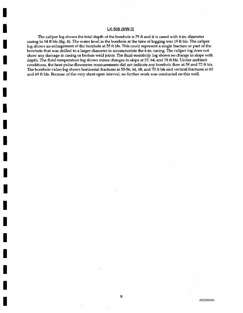
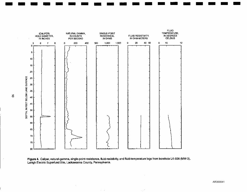
LK-5Q6 (MW-31
The caliper log shows the total depth of the borehole is 79 ft and it is cased with 6-in.-diameter casing to 54 ft bis (fig. 4). The water level in the borehole at the time of logging was 19 ft bis. The caliper log shows an enlargement of the borehole at 55 ft bis. This could represent a single fracture or part of the borehole that was drilled to a larger diameter to accommodate the 6-in. casing. The caliper log does not show any damage in casing or broken weld joints. The fluid-resistivity log shows no change in slope with depth. The fluid-temperature log shows minor changes in slope at 57, 64, and 78 ft bis. Under ambient conditions, the heat-pulse-flowmeter measurements did not indicate any borehole flow at 58 and 72 ft bis. The borehole video log shows horizontal fractures at 55-56,64,68, and 70 ft bis and vertical fractures at 65 and 69 ft bis. Because of the very short open interval, no further work was conducted on this well.
9 AR300040
(CALIPER) HOLE DIAMETER,
IN INCHES
NATURAL GAMMA, IN COUNTS
PER SECOND
SINGLE-POINT RESISTANCE,
IN OHMS FLUID RESISTIVITY,
IN OHM-METERS
FLUID TEMPERATURE,
IN DEGREES CELSIUS
200 400 500 1,000 1,500 40 50
Figure 4. Caliper, natural-gamma, single-point-resistance, fluid-resistivity, and fluid-temperature logs from borehole LK-506 (MW-3), Lehigh Electric Superfund Site, Lackawanna County, Pennsylvania.
AR300041
LK-507 fMW-4)
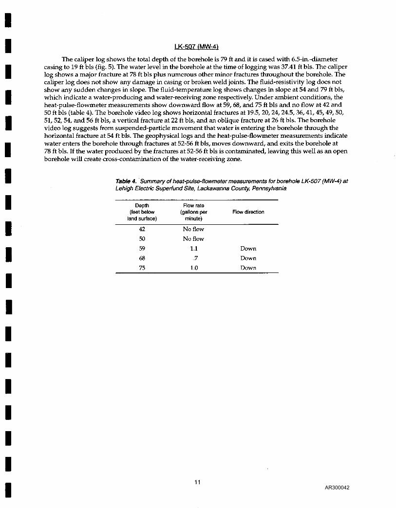
The caliper log shows the total depth of the borehole is 79 ft and it is cased with 6.5-in.-diameter casing to 19 ft bis (fig. 5). The water level in the borehole at the time of logging was 37.41 ft bis. The caliper log shows a major fracture at 78 ft bis plus numerous other minor fractures throughout the borehole. The caliper log does not show any damage in casing or broken weld joints. The fluid-resistivity log does not show any sudden changes in slope. The fluid-temperature log shows changes in slope at 54 and 79 ft bis, which indicate a water-producing and water-receiving zone respectively. Under ambient conditions, the heat-pulse-flowmeter measurements show downward flow at 59, 68, and 75 ft bis and no flow at 42 and 50 ft bis (table 4). The borehole video log shows horizontal fractures at 19.5,20,24, 24.5,36,41,45,49,50, 51,52,54, and 56 ft bis, a vertical fracture at 22 ft bis, and an oblique fracture at 26 ft bis. The borehole video log suggests from suspended-particle movement that water is entering the borehole through the horizontal fracture at 54 ft bis. The geophysical logs and the heat-pulse-flowmeter measurements indicate water enters the borehole through fractures at 52-56 ft bis, moves downward, and exits the borehole at 78 ft bis. If the water produced by the fractures at 52-56 ft bis is contaminated, leaving this well as an open borehole will create cross-contamination of the water-receiving zone.
Table 4. Summary of heat-pulse-flowmeter measurements for borehole LK-507 (MW-4) at Lehigh Electric Superfund Site, Lackawanna County, Pennsylvania
Depth Flow rate (feet below (gallons per Flow direction
land surface) minute)
42 No flow
50 No flow
59 1.1 Down
68 .7 Down
75 1.0 Down
11 AR300042

(CALIPER) HOLE DIAMETER,
IN INCHES
NATURAL GAMMA, IN COUNTS
PER SECOND
SINGLE-POINT RESISTANCE,
IN OHMS FLUID RESISTIVITY,
IN OHM-METERS
FLUID TEMPERATURE,
IN DEGREES CELSIUS
200 400 500 1,000 40 50 11
Figure 5. Caliper, natural-gamma, single-point-resistance, fluid-resistivity, and fluid-temperature logs from borehole LK-507 (MW-4), Lehigh Electric Superfund Site, Lackawanna County, Pennsylvania.
AR300043
SELECTED REFERENCES
Conger, R.W., 1996, Borehole geophysical Logging for Water-Resources Investigations in Pennsylvania: U.S. Geological Survey Fact Sheet 218-95,4p.
Hess, A.E., 1982, A heat-pulse flowmeter for measuring low velocities in boreholes: U.S. Geological Survey Open-File Report 82-699,49 p.
Keys, W.S., and MacCary, L.M., 1971, Application of borehole geophysics to Water-Resources Investigations: U.S. Geological Survey Techniques of Water-Resources Investigations, Book 2, Chapter El, 126 p.
Williams, J.H., and Conger, R.W., 1990, Preliminary delineation of contaminated water-bearing fractures intersected by open-hole bedrock wells: Grand Water Monitoring Review, Fall 1990, p. 118-121.
13 AR300044