evaluation of evaporator correlations for …
TRANSCRIPT

INTERNATIONAL JOURNAL OF RESEARCH IN AERONAUTICAL AND MECHANICAL ENGINEERING
WWW.IJRAME.COM ISSN (ONLINE): 2321-3051
Emerging Trends in Mechanical Engineering Proceedings of the
International Conference, ETME-2017, 27 & 28 December, 2017, Pg: -1-13
D.K.Ramesha - 1 -
EVALUATION OF EVAPORATOR CORRELATIONS
FOR HYDROCARBON REFRIGERANT PROPANE
(R290), ETHANE (R170), ETHYLENE (R1150) AS A
REPLACEMENT IN HORIZONTAL TUBE
DOMESTIC REFRIGERATOR [1]
D.K.Ramesha, [2]
Ganesh A, [2]
Pooja S, [2]
RohvinD’souza,
[2]
Surya Sagar V R [1]Associate Professor,[2]UG Scholar,
Department of Mechanical Engineering, University Visvesvaraya College of Engineering,
Bangalore University, Bengaluru-560001,Karnataka, India.
[email protected], [email protected]
ABSTRACT
Hydrocarbons are eco-friendly citing to their thermodynamic performance and non-pollutant
criteria making them suitable alternatives. This paper presents study of environment friendly
hydrocarbon refrigerant PROPANE(R-290), ETHANE (R170), ETHYLENE(R1150) best known
for their zero ozone depletion potential and minimal global warming effects in domestic
refrigerator. They provide additional benefits like high latent heat, lower discharge temperature,
feasibility with copper and additives and provide better performance with minimum energy
consumption comparatively. Based on theoretical results obtained from thermo physical properties and suitable correlation, it has been found that, Hydrocarbons can replace HFCs in the evaporator
of a domestic refrigerator without any system modifications. This leads to capital savings owing to
non-alteration of existing system. In this paper, three well known correlations have been evaluated
to find heat transfer co-efficient (HTC) which are in turn used to calculate theoretical heat transfer
area which are compared with actual heat transfer area. The least error for R290 is found with
Kandlikar correlation, for R170 is found with Gungor, and for R1150 is found with Kandlikar and
Gungor correlation which gives +10 % error. This upholds the replacement with hydrocarbon
refrigerant in existing evaporator system.
KEYWORDS: Hydrocarbon refrigerants, R290, R170, R1150, correlations, horizontal tube
refrigerator.

INTERNATIONAL JOURNAL OF RESEARCH IN AERONAUTICAL AND MECHANICAL ENGINEERING
WWW.IJRAME.COM ISSN (ONLINE): 2321-3051
Emerging Trends in Mechanical Engineering Proceedings of the
International Conference, ETME-2017, 27 & 28 December, 2017, Pg: -1-13
D.K.Ramesha - 2 -
INTRODUCTION:
In the early 1900s natural refrigerants such as ammonia, carbon dioxide, and sulphur dioxide were
commonly used. They possessed toxicity and were found hazardous. During 1930s,
chlorofluorocarbons (CFCs) and hydrochloro fluorocarbons (HCFCs) emerged as safer alternative
refrigerants with additional benefits such as stability, non–toxicity, non–flammability, better
material compatibility and thermodynamic properties. This revolutionized the Refrigeration and
Air Conditioning sector leading to their wide spread use in domestic and industrial applications
throughout the world. Researches have shown that earth‟s ozone layer, which protects the earth‟s
surface from harmful effects of UV radiation is depleting because of chlorine presence in the
stratosphere. The primary cause for such harm in CFCs and HCFCs are large class of chlorine containing chemicals, which rise up to the stratosphere where they react with ozone leading to
convert more ozone to oxygen. This concern has effected in a number of international treaties
urging for gradual phase out of halogenated fluids. Since 1996, developed countries have taken
steps in banning of CFCs and is estimated that by 2030, production and usage of CFCs will be
prohibited in the entire world. Also is the case for partially halogenated HCFCs [1].
The contribution of refrigeration system towards global warming can be viewed in two ways,
namely direct and indirect. The direct effect occurs because of the leakage of refrigerant and
whose effect can be connected directly with the global warming potential of the refrigerant used.
Whereas carbon-dioxide emission from combustion of fossil fuels, which provides electricity to
drive compressors can be viewed as indirect. In case of hermetic equipment where refrigerant
leakage is low, energy consumption plays a key parameter in analyzing environmental impact of
refrigerants. If refrigerant leakage is large as in car air-conditioners, the global warming potential
dominates but energy costs are still of interest [2].
The quest for eco-friendly refrigerants which provide no harm to our environment and shielding
ozone layer are moving in quick pace. Air, ammonia, carbon dioxide, hydrocarbons and water are
accepted as the only class of refrigerants with no ozone depletion potential, low global warming
trait and cleaner production ways by all national governments except the Environment Protection
Agency of the United State. Noteworthy contributions are made in China and Germany in this
direction while other European countries are now requiring phase-out of harmful refrigerants. P. J.
vanderWeyde of Philadelphia invented hydrocarbon refrigerants in 1866 [3].
Ethane R170, propane R290 and isobutane R600a were successfully marketed by the Linde
companies in the 1920s and 1930s. Since 1967 hydrocarbon refrigerants have liquified natural gas
in plants which are now larger than 100 MW of cooling. Hydrocarbon refrigerants for domestic appliances were revived in Germany in 1992 and R600a refrigerators have spread worldwide
[4].Research has shown that hydrocarbons are good alternative to existing refrigerants. Hydrocarbons, propane (R–290) and isobutane (R–600a) were among the first refrigerants, but due to their flammability and safety purposes, their use was abandoned and the direction of

INTERNATIONAL JOURNAL OF RESEARCH IN AERONAUTICAL AND MECHANICAL ENGINEERING
WWW.IJRAME.COM ISSN (ONLINE): 2321-3051
Emerging Trends in Mechanical Engineering Proceedings of the
International Conference, ETME-2017, 27 & 28 December, 2017, Pg: -1-13
D.K.Ramesha - 3 -
researches was shifted towards a safer and inert class of refrigerants [5].Propane (R–290) is
widely being used in heat pumps, air conditioners and commercial refrigeration systems. Because
of absence of fluorine content in Hydrocarbon refrigerants, they are viewed as alternatives to HFC
refrigerants. Hydrocarbons (HCs) are the class of natural occurring substances comprising of
propane, butaneand pentane. HCs are excellent refrigerants in many ways like energy efficiency,
critical point, solubility, transport, heat transfer properties and environmentally sound but their
major concern is their flammability [6].
The paper deals with evaluation of 3 well known flow boiling heat transfer correlation used to find the HTC at liquid phase, two phase and superheated phase and finally calculate the heat transfer
area. The actual heat transfer area is calculated using evaporator dimensions. The percentage error
between actual heat transfer area v/s theoretical heat transfer area serves to conclude the best
correlation which accounts for all factors involved and thereby propose replacement with
hydrocarbon refrigerant in the horizontal evaporator without any significant modifications.
METHODOLOGY:
The methodology carried out can be put up as finding the best empirical evaporator correlation for
two-phase heat transfer co-efficient in order to obtain the overall heat transfer co-efficient in
mixed phase thereby calculating the heat transfer area required for the given capacity. These
results are validated by comparing with the evaporator dimensions of a 95W BOSCH domestic
refrigerator.
In evaporator, the phase of refrigerant changes continuously leading to a continuous change in the
heat transfer co-efficient. Thus we need to find out the heat transfer co-efficient in the two-phase
region at a particular composition and region and incorporate it in the overall heat transfer
coefficient and find the area using heat exchanger design relation.
In this paper we consider LMTD method to find the area of the evaporator required.
Q = U.A.LMTD
LMTD= Log mean temperaturedifference=

INTERNATIONAL JOURNAL OF RESEARCH IN AERONAUTICAL AND MECHANICAL ENGINEERING
WWW.IJRAME.COM ISSN (ONLINE): 2321-3051
Emerging Trends in Mechanical Engineering Proceedings of the
International Conference, ETME-2017, 27 & 28 December, 2017, Pg: -1-13
D.K.Ramesha - 4 -
Heat transfer areas in finned tube evaporators:
Bare tube area, Ab= (tube perimeter)*(number of fin passages)*(number of tubes)*(width of each
passage) = (πd0) (1/D) (1/B) (D-t)
Ab= 0 m2 per m2 face per row
Fin area, Af= (number of fins)*(two sides of fins)*(width of fin per row)*{number of tubes *(area
of cross section of each tube)} = (1/D) 2{1*C-(1/B)π(d02/4)}
Af= m2 per m2 face per row
Total heat transfer area, A0= Bare tube area+Fin area
A0t=Ab+Afm2 per m2 face per row
Air side heat transfer coefficient:
A simple expression has been proposed by Air conditioning and Refrigeration Institute, Arlington
Va.(1972), which is as follows:
Overall heat transfer coefficient:
A general expression for overall heat transfer coefficient is given by:

INTERNATIONAL JOURNAL OF RESEARCH IN AERONAUTICAL AND MECHANICAL ENGINEERING
WWW.IJRAME.COM ISSN (ONLINE): 2321-3051
Emerging Trends in Mechanical Engineering Proceedings of the
International Conference, ETME-2017, 27 & 28 December, 2017, Pg: -1-13
D.K.Ramesha - 5 -
In the above expression, h is the convective heat transfer coefficient, Af and Ab are the finned and
bare tube areas of the heat exchanger respectively, and „ƞ‟ is the fin efficiency. Subscripts “i” and
“o” stand for inner and outer sides Rf is the resistance due to fouling if need to be considered. A0
and Ai are the inside and outside heat transfer area respectively.
The evaporator particulars considered in the paper are as follows:
Refrigerant R290 Tube material = Copper
Thermal conductivity = 400W/mk
Mass flow rate of the refrigerant = 0.0003Kg/s
Table 1: Tube dimensions
Outer diameter of the tube (D0) 9.53mm
Inner diameter of the tube (Di) 7.53mm
Root diameter (Dr) 12.45mm
Fins pitch (P) 1.8mm
Fin height (h) 25mm
Fin thickness (t) 0.25mm
Fin spacing (s) 1.55mm
Fins/inch 14
Fins/metre 551
Transverse Pitch (B) 0.025mm
Longitudinal pitch (C)
0.0125mm
Length of the evaporator (L) 890mm
Height of the evaporator (H) 760mm
Following are the correlations employed to find the HTC and Heat transfer area:
Kandlikar’s correlation (1983)
=C1C0C2
(25Frlo)C5
+C3(Bo)C4
Ffl

INTERNATIONAL JOURNAL OF RESEARCH IN AERONAUTICAL AND MECHANICAL ENGINEERING
WWW.IJRAME.COM ISSN (ONLINE): 2321-3051
Emerging Trends in Mechanical Engineering Proceedings of the
International Conference, ETME-2017, 27 & 28 December, 2017, Pg: -1-13
D.K.Ramesha - 6 -
The values of constants 𝐶1 - 𝐶5 are given in Table 2
Table 2: Values of Constants
Constant Convective region Nucleate boiling
Region
C1 1.1360 0.6683
C2 -0.9 -0.2
C3 667.2 1058
C4 0.7 0.7
C5 0.3 0.3
C5=0,for vertical tubes and for horizontal tubes with Frl>0.04
C0<0.65 – Convective boiling region
C0>0.65 - Nucleate boiling region
C0= Convection number = ( 0.5( )0.8
B0 = Boiling number =q/(Ghfg)
G= m/Ai kg/m2-s
q= U*(TH-TS)W
U=( 2-K
hcb=(F0*hl0)W/m2-K
F0=F*(1-x)
F=2.35(0.213+1/Xtt)
1/Xtt= ( )0.9 * ( 0.5 * ( 0.1
Frl0=
C5=0 for Frl0>0.04
Chaddock-Brunemann’s Correlation:
Htp=1.91h1*[Bo.104+1.5(1/Xtt)0.67]0.6

INTERNATIONAL JOURNAL OF RESEARCH IN AERONAUTICAL AND MECHANICAL ENGINEERING
WWW.IJRAME.COM ISSN (ONLINE): 2321-3051
Emerging Trends in Mechanical Engineering Proceedings of the
International Conference, ETME-2017, 27 & 28 December, 2017, Pg: -1-13
D.K.Ramesha - 7 -
Bo=Boiling Number=
Xtt=( 0.9( 0.5*( 0.1……Lockhart-Martenelli parameter
Gungor-Winterton Correlation:
Htp=(SS2+FF2)hspl Where hspl, is calculate with (2), and the factors S,S2,F, and F2 are calculated by
S=1+3000Bo0.86
F=1.12(0.75
(0.41
S2= Frl(0.1-2Frl)
if horizontal and Frl<0.05
1 otherwise
F2= Frl1/2
if horizontal and Frl<0.05
1 otherwise
RESULTS AND DISCUSSION:
The plot shows kandlikar correlation gives a higher value in case of R290 and lower value for
R170.This is due to lower value of martenalli factor which in turn depend on higher density and
viscosity values at liquid phase.
Fig.1:shows the variation of 2phase HTC with temperature for R290, R170, R1150 using
Kandlikar correlation.

INTERNATIONAL JOURNAL OF RESEARCH IN AERONAUTICAL AND MECHANICAL ENGINEERING
WWW.IJRAME.COM ISSN (ONLINE): 2321-3051
Emerging Trends in Mechanical Engineering Proceedings of the
International Conference, ETME-2017, 27 & 28 December, 2017, Pg: -1-13
D.K.Ramesha - 8 -
Fig.2:shows the variation of 2phase HTC with temperature for R290, R170 and R1150 using
Chaddock correlation.
The plot shows Chaddock correlation gives a higher value in case of R1150 and lower value for
R170 while the value for R290 lies in between them. This trend is obtained due to the influence of higher values of Latent heat of vapourisation.
Fig.3: shows the variation of 2phase HTC with temperature for R290, R170, R1150 using Gungor correlation
The plot shows Gungor correlation gives a higher value in case of R1150 and lower value for
R290. The higher values of liquid heat transfer co-efficient obtained from Dittus boelter
correlation is found to be the reason for the variation of 2phase heat transfer co-efficient.

INTERNATIONAL JOURNAL OF RESEARCH IN AERONAUTICAL AND MECHANICAL ENGINEERING
WWW.IJRAME.COM ISSN (ONLINE): 2321-3051
Emerging Trends in Mechanical Engineering Proceedings of the
International Conference, ETME-2017, 27 & 28 December, 2017, Pg: -1-13
D.K.Ramesha - 9 -
Fig.4: shows the Heat Transfer areas obtained from Kandlikar, Chaddock and Gungor correlation
at working temperatures for R290.
Kandlikar correlation gives the area near to the actual heat transfer area obtained from system
dimensions
Fig.5:shows the Heat Transfer areas obtained from Kandlikar, Chaddock and Gungor correlation
at working temperatures for R170
Gungor correlation gives the area near to the actual heat transfer area obtained from system dimensions.
INTERNATIONAL JOURNAL OF RESEARCH IN AERONAUTICAL AND MECHANICAL ENGINEERING
WWW.IJRAME.COM ISSN (ONLINE): 2321-3051
Emerging Trends in Mechanical Engineering Proceedings of the
International Conference, ETME-2017, 27 & 28 December, 2017, Pg: -1-13
D.K.Ramesha - 10
-
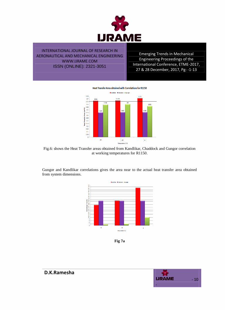
Fig.6: shows the Heat Transfer areas obtained from Kandlikar, Chaddock and Gungor correlation
at working temperatures for R1150.
Gungor and Kandlikar correlations gives the area near to the actual heat transfer area obtained
from system dimensions.
Fig 7a
INTERNATIONAL JOURNAL OF RESEARCH IN AERONAUTICAL AND MECHANICAL ENGINEERING
WWW.IJRAME.COM ISSN (ONLINE): 2321-3051
Emerging Trends in Mechanical Engineering Proceedings of the
International Conference, ETME-2017, 27 & 28 December, 2017, Pg: -1-13
D.K.Ramesha - 11
-
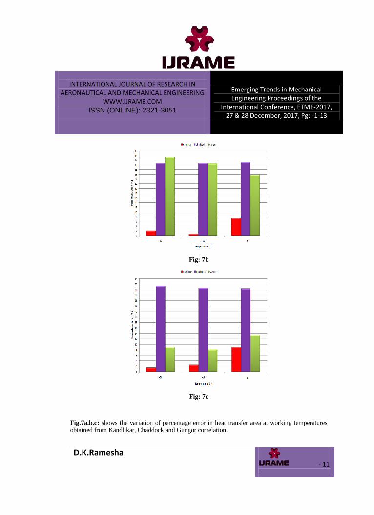
Fig: 7b
Fig: 7c
Fig.7a.b.c: shows the variation of percentage error in heat transfer area at working temperatures
obtained from Kandlikar, Chaddock and Gungor correlation.

INTERNATIONAL JOURNAL OF RESEARCH IN AERONAUTICAL AND MECHANICAL ENGINEERING
WWW.IJRAME.COM ISSN (ONLINE): 2321-3051
Emerging Trends in Mechanical Engineering Proceedings of the
International Conference, ETME-2017, 27 & 28 December, 2017, Pg: -1-13
D.K.Ramesha - 12
-
The plot shows Kandlikar and Gungor gives least error with R1150 while Kandlikar alone best
predicts for R170, Gungor for R170.
CONCLUSIONS:
As per the Kyoto and Montreal protocols, the harmful refrigerants are to be phased out and are to
be replaced with alternate environmental friendly refrigerants. The objective of this paper is to
evaluate environmental friendly hydrocarbon refrigerant as a replacement in the existing
evaporator. On the basis of results, the following conclusions may be drawn.
Heat transfer co-efficient at two phase for three temperatures encountered in the evaporator have
been calculated by three well known evaporator correlations and are in turn used to find the
theoretical heat transfer area of the evaporator. This area is compared with actual heat transfer area obtained from evaporator dimensions. This paper shows that kandlikar(for R290, R1150) and
Gungor(R170) correlation gives the least percentage error comparatively . Thus hydrocarbon
refrigerants may replace HFCs(R-134a) without any system modifications in the evaporator.
REFERENCES:
[1]D.V.Raghunatha Reddy, P.Bhramara, K.Govindarajulu ,Hydrocarbon refrigerant mixtures as an
alternative to R134a in domestic refrigeration system: the state-of-the-art review, International
Journal of Scientific & Engineering Research, Volume 7, Issue 6, June-2016 87 ISSN 2229-5518.
[2].Maclaine-cross I. L., Leonardi E., June 1997, “Why Hydrocarbons Save Energy”, School of Mechanical and Manufacturing Engineering The University of New South Wales Sydney NSW,
Australia 2052, Published in AIRAH Journal, Volume 51 No. 6.
[3].Quraishi M. A., Wankhede U. S., Jan-Feb. 2013, “Use of Hydrocarbons and Other Blends as
Refrigerant.” International Journal of Modern Engineering Research (IJMER) Vol.3, Issue.1, pp-
250-253,ISSN: 2249-6645.
[4].Usage and Risk of Hydrocarbon Refrigerants in Motor Cars for Australia and the United
States, I. L. Maclaine-cross, School of Mechanical and Manufacturing Engineering, The
University of New South,Wales, UNSW Sydney 2052, Australia.
[5]Zhanru Zhou, Xiande Fang, and Dingkun LiEvaluation of Correlations of Flow Boiling Heat
Transfer of R22 in Horizontal Channels.Institute of Air Conditioning and Refrigeration, Nanjing
University of Aeronautics and Astronautics, 29 Yudao Street, Nanjing 210016, China.

INTERNATIONAL JOURNAL OF RESEARCH IN AERONAUTICAL AND MECHANICAL ENGINEERING
WWW.IJRAME.COM ISSN (ONLINE): 2321-3051
Emerging Trends in Mechanical Engineering Proceedings of the
International Conference, ETME-2017, 27 & 28 December, 2017, Pg: -1-13
D.K.Ramesha - 13
-
[6].G.A. Longo , A. Gasparella, R. Sartori , “Experimental heat transfer coefficients during
refrigerant vaporization and condensation inside herringbone-type plate heat exchangers with
enhanced surfaces”, International Journal of Heat and Mass Transfer 47 (2004) 4125–4136. 26
June 2004.
[7].ASHRAE 2001, 2001 ASHRAE Handbook Fundamentals, American Society ofHeating,
Refrigerating and Air Conditioning Engineers, Inc., Atlanta.
[8].Sadikkakac, “Boilers, Evaporators and condensers”, John Wiley & Sons,1991.
[9]. Cengel Y. A., Bole M. A., Thermodynamics,An Engineering Approach.
[10].S. G. Kandlikar, “A General Correlation for Saturated Two-Phase Flow Boiling Heat Transfer Inside Horizontal and Vertical Tubes”, Mechanical Engineering Department,Rochester
Institute of Technology, Rochester.
[11]. Kays W.M, London A.L, “Convective heat transfer,McGraw-Hill”,3rd edition,1984.
[12]. Ramesh K. Shah and DušanP.Sekulic , “Fundamentals of Heat Exchanger Design”., John
Wiley & Sons, 2003.
[13].Sadikkakac, Hongtan Liu, “Heat exchangers selection, rating and thermal design”,2nd
edition.
[14]. De-Yi Shang, “Free Convection Film Flows and Heat Transfer‟‟ Second Edition, Springer-
Verlag Berlin Heidelberg 2012.
[15].J.K. Dabas, Sudhir Kumar, A.K. Dodeja and K.S. Kasana, “Modelling of Horizontal Shell
and Tube Dry Expansion Refrigerant Evaporator”, International Journal of Advanced Mechanical
Engineering. ISSN 2250-3234 Volume 4, Number 1 (2014). [16]. WOLVERINE (1984) “Wolverine Tube Heat Transfer Data Book Low Fin Tubes”.
[17].WEBB, R. L. and GUPTE, N. S., “Heat Trans. Eng., 13 (3) 58. A critical review of
correlations for convective vaporization in tubes and tube banks”.
[18]. WEBBER, W. O. (1960) Chemical Engineering, Wilkinson, W. L. And Edwards,M. F.
(1972) Chemical Engineering, “Heat transfer in agitated vessels”.
[19].P.S. Ravi ,DrArkantiKrishnaiah , Dr Suresh Akella, DrMdAzizuddin , “Evaluation of Inside
Heat Transfer Coefficient of Roll Bond Evaporator for Room Air Conditioner”,IJIRSET,Vol.4,
Issue 5 , May 2015.