evaluation of a mems deformable mirror for an adaptive optics test bench
TRANSCRIPT
Evaluation of a MEMS deformable mirror for an adaptive optics test bench
Brian P. Wallace, Peter J. Hampton, Colin H. Bradley and Rodolphe Conan University of Victoria, Dept. of Mechanical Engineering
Victoria, BC, Canada, V8W 2Y2 [email protected]
Abstract: An adaptive optics (AO) test bed has been designed and implemented to evaluate the effectiveness of the next generation of AO components and their associated control system. The optical design presented herein incorporates a turbulence generator, tip-tilt mirror, 140-actuator micro-electro-mechanical-system (MEMS) deformable mirror, Shack-Hartmann wave front sensor, and a science camera. This system has been operated in a closed AO loop at a 261 Hz sample rate. This paper focuses on the performance of the MEMS DM. It was examined using an interferometer to determine the influence functions, response time, and the quadratic relationship of displacement of the actuators to an applied voltage.
©2006 Optical Society of America
OCIS codes: (010.1080) Adaptive Optics
References and links
1. S. P. Kotova et al., “Modal liquid crystal wavefront corrector,” Opt. Express 10, 1258 (2002). 2. M. Langlois, C. D. Saunter, C. N. Dunlop, R. M. Myers, and G. D. Love, “Multi-conjugate adaptive
optics: laboratory experience,” Opt. Express 12, 1689 (2004). 3. C. Paterson, I. Munro, and J. C. Dainty, “A low cost adaptive optics system using a membrane mirror,”
Opt. Express 6, 175 (2000). 4. J. A. Perreault, T. G. Bifano, B. M. Levine, and M. N. Horenstein, “Adaptive optic correction using micro-
electro-mechanical deformable mirrors,” Opt. Eng. 41, 561-566 Mar. 2002. 5. T. Bifano, P. Bierden, H. Zhu, S. Cornelissen, and J. H. Kim, “Megapixel wavefront correctors,” in
Advancements in Adaptive Optics, D. B. Calia, B. L. Ellerbroek, and R. Ragazzoni, eds., Proc. SPIE 5490, 1472-1484 (2004).
6. B. A. Macintosh et al., “The Gemini Planet Imager,” in Advances in Adaptive Optics II, B. L. Ellerbroek and D. B. Calia, eds., Proc. SPIE 6272, 62720L (2006).
7. B. L. Ellerbroek et al., “A conceptual design for the Thirty Meter Telescope adaptive optics system,” in Advances in Adaptive Optics II, B. L. Ellerbroek, D. B. Calia, eds., Proc. SPIE 6272, 62720D (2006).
8. R. Conan, P. Hampton, and C. Bradley, “The woofer-tweeter experiment,” in Advances in Adaptive Optics II, edited by B.L. Ellerbroek, D.B. Calia, eds., Proc. SPIE 6272, 62721V (2006).
9. M. J. Booth, T. Wilson, T. Ota and T. Sugiura, “Dynamic axial position control of a laser trapped particle by wave-front modification,” Opt. Lett. 28, 465-468, 2003.
10. O. Keskin, L. Jolissaint, and C. Bradley, “Hot air turbulence generator for the testing of adaptive optics systems: principles and characterization,” Appl. Opt. 45, 4888-4897 (2006).
11. W. H. Southwell, “Wave-front estimation from wave-front slope measurements,” J. Opt. Soc. Am. 70, 998 (1980).
12. R. J. Noll, “Zernike polynomials and atmospheric turbulence,” J. Opt. Soc. Am. 66, 207-211, 1976.
1. Introduction
Several high-resolution wavefront correctors have been proposed to meet the needs of future Extremely Large Telescopes (ELT) including: liquid-crystal spatial light modulators [1,2], membrane mirrors [3], and micro electro-mechanical systems (MEMS) [4]. MEMS deformable mirrors (DMs) have been demonstrated with one thousand actuators [5] and DMs having several thousand actuators are being prototyped.
MEMS mirrors are beginning to be included in the design of ambitious adaptive optics (AO) projects. The Gemini Planet Imager (GPI) will employ a 2000 actuator MEMS DM with
#72912 - $15.00 USD Received 10 July 2006; revised 27 September 2006; accepted 8 October 2006
(C) 2006 OSA 30 October 2006 / Vol. 14, No. 22 / OPTICS EXPRESS 10132
the goal of directly imaging an extra-solar Jovian scale planet. This instrument is planned to be installed on the 8 m class Gemini South telescope in 2010 [6]. This goal is also a motivation for the construction of the Thirty Meter Telescope (TMT). This project will require DMs with up to 15,000 actuators due to the larger primary mirror [7]. The adaptive optics team at the University of Victoria has begun proof of concept work for control systems for the TMT project using multiple DMs in the optical path. This work also uses a MEMS DM for the high order correction [8]. MEMS devices, such as deformable mirrors, are also finding application in other fields, such as bio-photonics. For example, a MEMS-based DM was used to manipulate an optical wavefront for the creation of an optical-tweezer system [9].
The design of an AO test bench incorporating a turbulence generator, tip-tilt mirror, 140-actuator MEMS DM and Shack-Hartmann wavefront sensor (WFS) are presented. The paper is laid out as follows: Section 2 describes the test bench optical design; Section 3 discusses the characterization of the MEMS DM; and finally, Section 4 summarizes the key experimental findings.
2. Optical design
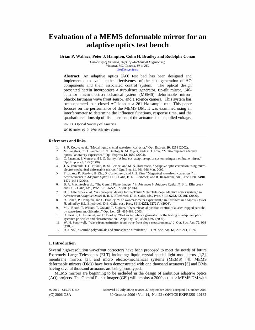
The AO test bench optical layout is illustrated in Fig. 1 and discussed below. A 632.8 nm HeNe laser, with a spatial filter and collimator, was used as a light source producing a 22 mm diameter beam. Utilizing this beam size, the turbulence generator (a hot air mixing chamber), was capable of producing turbulence with D/ro of at least 10 [10]. Following the turbulence generator, a 200 mm and 60 mm focal lens pair reduces the beam to a size compatible with the reflective area of the MEMS DM (approximately 3 mm x 3 mm). An iris was used to establish the pupil of the system and illuminate the interior 10 actuators across the DM reflective membrane. The iris was followed by a pair of 150 mm lenses that form an image of the pupil on the 2-axis tip-tilt mirror (Polytec PI S330). The tip-tilt platform is capable of ±1 mrad angular deflection with a slew rate of 0.5 rad/sec. Another lens pair relayed the pupil image to the deformable and reference mirrors. The deformable mirror is a MEMS type mirror (Boston Micromachines Inc.) with 140 actuators in a 12 by 12 grid (there are no actuators at each of the 4 corners).
120.00 MM
LaserSource
Turbulence Generator
200 mm
60 mm
150 mm
150 mm
Tip-TiltMirror
100 mm
100 mm
Reference Mirror
BeamSplitter
DeformableMirror
200 mm
125 mm
BeamSplitter
FoldMirror
50 mm
ScienceCamera
WavefrontSensor
Collimator
Iris
Windows
Fig. 1. Science and WFS optical paths on the test bed. (Lens focal lengths are indicated.)
A 200 mm and 124 mm focal length lens pair was used to reduce the pupil image on to the Shack-Hartmann style wave front sensor (WFS). The WFS is comprised of a high-speed digital CCD camera (Dalsa: CA-D1-0128A) and a lenslet array (Adaptive Optics Associates 0188-8.0-S). The lenslet array has a pitch of 188 μm. This lenslet array was chosen in order to allow tilt up to 2.56 mrad from center without a spot moving from its sub-aperture. This is approximately double the maximum single direction stroke of the tip-tilt mirror. As shown in
#72912 - $15.00 USD Received 10 July 2006; revised 27 September 2006; accepted 8 October 2006
(C) 2006 OSA 30 October 2006 / Vol. 14, No. 22 / OPTICS EXPRESS 10133
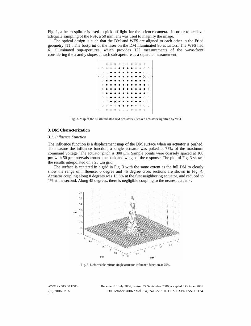
Fig. 1, a beam splitter is used to pick-off light for the science camera. In order to achieve adequate sampling of the PSF, a 50 mm lens was used to magnify the image.
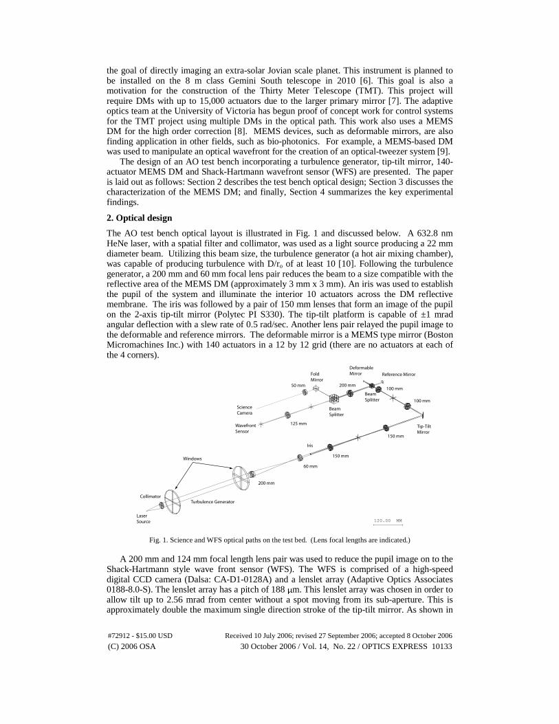
The optical design is such that the DM and WFS are aligned to each other in the Fried geometry [11]. The footprint of the laser on the DM illuminated 80 actuators. The WFS had 61 illuminated sup-apertures, which provides 122 measurements of the wave-front considering the x and y slopes at each sub-aperture as a separate measurement.
Fig. 2. Map of the 80 illuminated DM actuators. (Broken actuators signified by ‘x’.)
3. DM Characterization
3.1. Influence Function
The influence function is a displacement map of the DM surface when an actuator is pushed. To measure the influence function, a single actuator was poked at 75% of the maximum command voltage. The actuator pitch is 300 μm. Sample points were coarsely spaced at 100 μm with 50 μm intervals around the peak and wings of the response. The plot of Fig. 3 shows the results interpolated on a 25 μm grid.
The surface is centered in a grid in Fig. 3 with the same extent as the full DM to clearly show the range of influence. 0 degree and 45 degree cross sections are shown in Fig. 4. Actuator coupling along 0 degrees was 13.5% at the first neighboring actuator, and reduced to 1% at the second. Along 45 degrees, there is negligible coupling to the nearest actuator.
Fig. 3. Deformable mirror single actuator influence function at 75%.
#72912 - $15.00 USD Received 10 July 2006; revised 27 September 2006; accepted 8 October 2006
(C) 2006 OSA 30 October 2006 / Vol. 14, No. 22 / OPTICS EXPRESS 10134
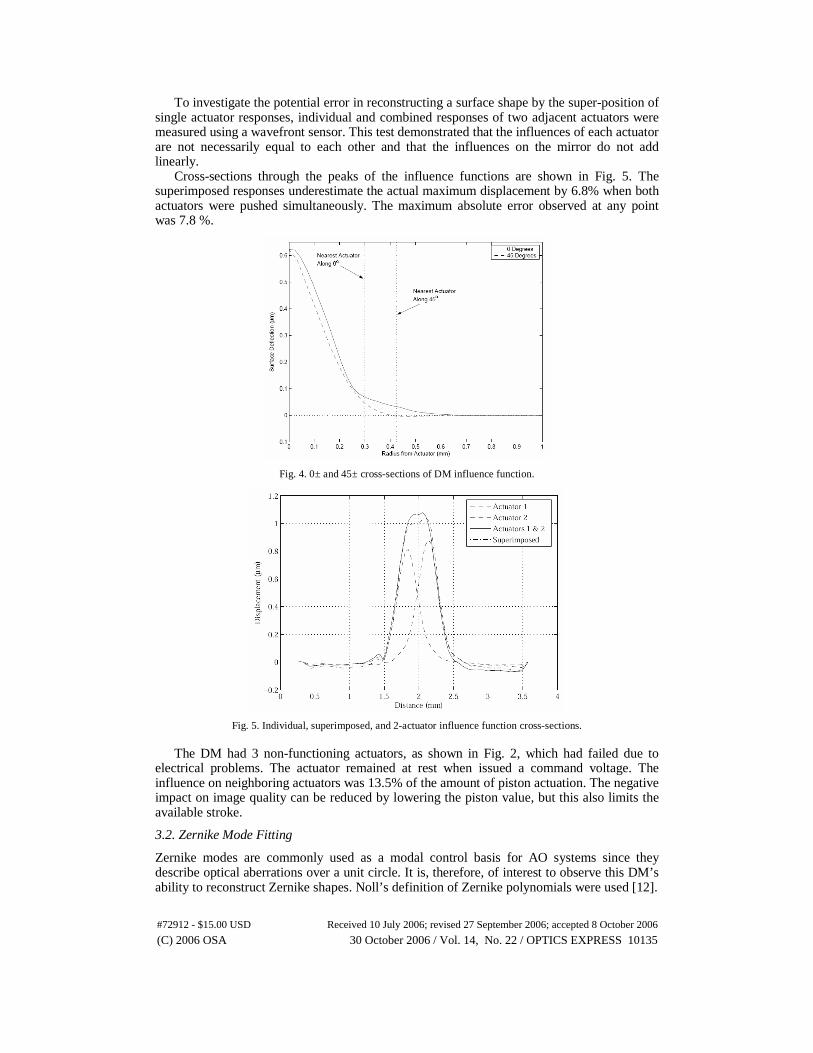
To investigate the potential error in reconstructing a surface shape by the super-position of single actuator responses, individual and combined responses of two adjacent actuators were measured using a wavefront sensor. This test demonstrated that the influences of each actuator are not necessarily equal to each other and that the influences on the mirror do not add linearly.
Cross-sections through the peaks of the influence functions are shown in Fig. 5. The superimposed responses underestimate the actual maximum displacement by 6.8% when both actuators were pushed simultaneously. The maximum absolute error observed at any point was 7.8 %.
Fig. 4. 0± and 45± cross-sections of DM influence function.
Fig. 5. Individual, superimposed, and 2-actuator influence function cross-sections.
The DM had 3 non-functioning actuators, as shown in Fig. 2, which had failed due to
electrical problems. The actuator remained at rest when issued a command voltage. The influence on neighboring actuators was 13.5% of the amount of piston actuation. The negative impact on image quality can be reduced by lowering the piston value, but this also limits the available stroke.
3.2. Zernike Mode Fitting
Zernike modes are commonly used as a modal control basis for AO systems since they describe optical aberrations over a unit circle. It is, therefore, of interest to observe this DM’s ability to reconstruct Zernike shapes. Noll’s definition of Zernike polynomials were used [12].
#72912 - $15.00 USD Received 10 July 2006; revised 27 September 2006; accepted 8 October 2006
(C) 2006 OSA 30 October 2006 / Vol. 14, No. 22 / OPTICS EXPRESS 10135
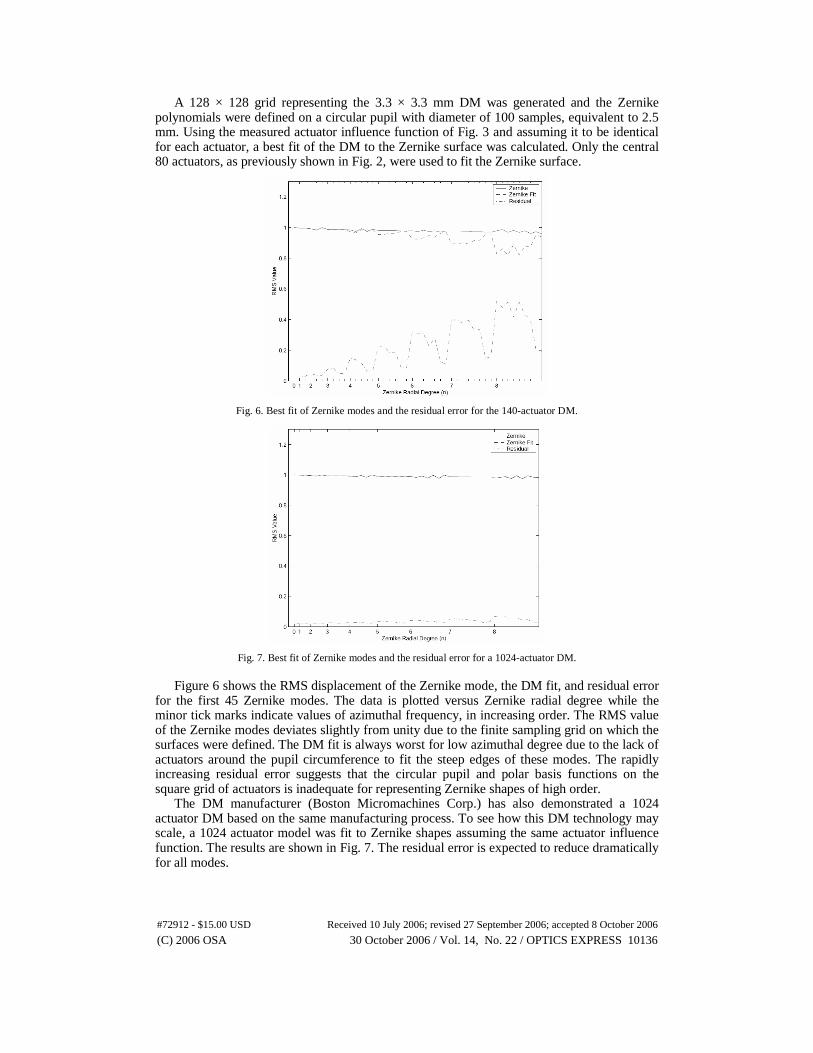
A 128 × 128 grid representing the 3.3 × 3.3 mm DM was generated and the Zernike polynomials were defined on a circular pupil with diameter of 100 samples, equivalent to 2.5 mm. Using the measured actuator influence function of Fig. 3 and assuming it to be identical for each actuator, a best fit of the DM to the Zernike surface was calculated. Only the central 80 actuators, as previously shown in Fig. 2, were used to fit the Zernike surface.
Fig. 6. Best fit of Zernike modes and the residual error for the 140-actuator DM.
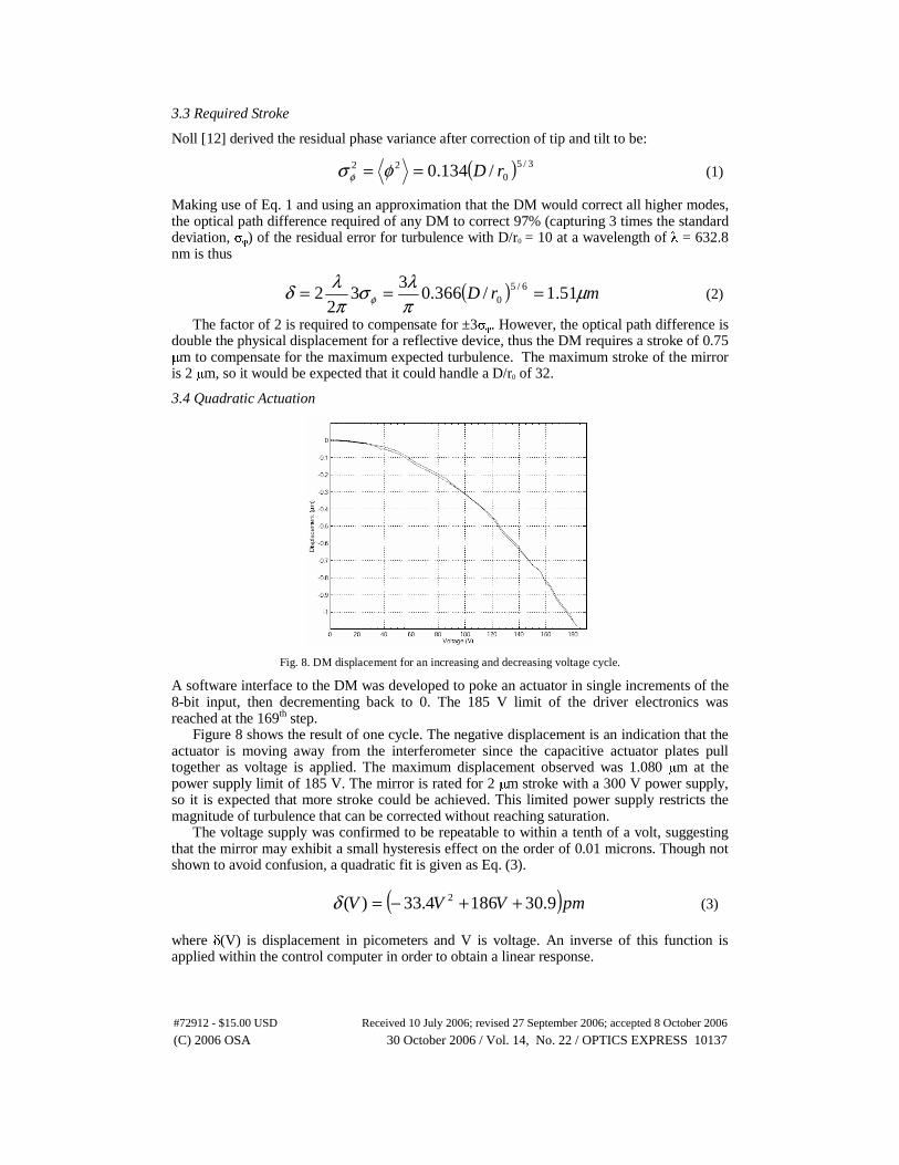
Fig. 7. Best fit of Zernike modes and the residual error for a 1024-actuator DM.
Figure 6 shows the RMS displacement of the Zernike mode, the DM fit, and residual error
for the first 45 Zernike modes. The data is plotted versus Zernike radial degree while the minor tick marks indicate values of azimuthal frequency, in increasing order. The RMS value of the Zernike modes deviates slightly from unity due to the finite sampling grid on which the surfaces were defined. The DM fit is always worst for low azimuthal degree due to the lack of actuators around the pupil circumference to fit the steep edges of these modes. The rapidly increasing residual error suggests that the circular pupil and polar basis functions on the square grid of actuators is inadequate for representing Zernike shapes of high order.
The DM manufacturer (Boston Micromachines Corp.) has also demonstrated a 1024 actuator DM based on the same manufacturing process. To see how this DM technology may scale, a 1024 actuator model was fit to Zernike shapes assuming the same actuator influence function. The results are shown in Fig. 7. The residual error is expected to reduce dramatically for all modes.
#72912 - $15.00 USD Received 10 July 2006; revised 27 September 2006; accepted 8 October 2006
(C) 2006 OSA 30 October 2006 / Vol. 14, No. 22 / OPTICS EXPRESS 10136
3.3 Required Stroke
Noll [12] derived the residual phase variance after correction of tip and tilt to be:
( ) 3/50
22 /134.0 rD== φσ φ (1)
Making use of Eq. 1 and using an approximation that the DM would correct all higher modes, the optical path difference required of any DM to correct 97% (capturing 3 times the standard deviation, σφ) of the residual error for turbulence with D/r0 = 10 at a wavelength of λ = 632.8 nm is thus
( ) mrD μπλσ
πλδ φ 51.1/366.0
33
22 6/5
0 === (2)
The factor of 2 is required to compensate for ±3σφ. However, the optical path difference is double the physical displacement for a reflective device, thus the DM requires a stroke of 0.75 μm to compensate for the maximum expected turbulence. The maximum stroke of the mirror is 2 μm, so it would be expected that it could handle a D/r0 of 32.
3.4 Quadratic Actuation
Fig. 8. DM displacement for an increasing and decreasing voltage cycle.
A software interface to the DM was developed to poke an actuator in single increments of the 8-bit input, then decrementing back to 0. The 185 V limit of the driver electronics was reached at the 169th step.
Figure 8 shows the result of one cycle. The negative displacement is an indication that the actuator is moving away from the interferometer since the capacitive actuator plates pull together as voltage is applied. The maximum displacement observed was 1.080 μm at the power supply limit of 185 V. The mirror is rated for 2 μm stroke with a 300 V power supply, so it is expected that more stroke could be achieved. This limited power supply restricts the magnitude of turbulence that can be corrected without reaching saturation.
The voltage supply was confirmed to be repeatable to within a tenth of a volt, suggesting that the mirror may exhibit a small hysteresis effect on the order of 0.01 microns. Though not shown to avoid confusion, a quadratic fit is given as Eq. (3).
( )pmVVV 9.301864.33)( 2 ++−=δ (3)
where δ(V) is displacement in picometers and V is voltage. An inverse of this function is applied within the control computer in order to obtain a linear response.
#72912 - $15.00 USD Received 10 July 2006; revised 27 September 2006; accepted 8 October 2006
(C) 2006 OSA 30 October 2006 / Vol. 14, No. 22 / OPTICS EXPRESS 10137
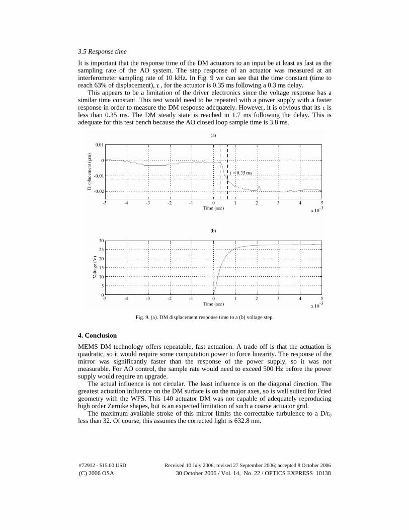
3.5 Response time
It is important that the response time of the DM actuators to an input be at least as fast as the sampling rate of the AO system. The step response of an actuator was measured at an interferometer sampling rate of 10 kHz. In Fig. 9 we can see that the time constant (time to reach 63% of displacement), τ , for the actuator is 0.35 ms following a 0.3 ms delay.
This appears to be a limitation of the driver electronics since the voltage response has a similar time constant. This test would need to be repeated with a power supply with a faster response in order to measure the DM response adequately. However, it is obvious that its τ is less than 0.35 ms. The DM steady state is reached in 1.7 ms following the delay. This is adequate for this test bench because the AO closed loop sample time is 3.8 ms.
Fig. 9. (a). DM displacement response time to a (b) voltage step.
4. Conclusion
MEMS DM technology offers repeatable, fast actuation. A trade off is that the actuation is quadratic, so it would require some computation power to force linearity. The response of the mirror was significantly faster than the response of the power supply, so it was not measurable. For AO control, the sample rate would need to exceed 500 Hz before the power supply would require an upgrade.
The actual influence is not circular. The least influence is on the diagonal direction. The greatest actuation influence on the DM surface is on the major axes, so is well suited for Fried geometry with the WFS. This 140 actuator DM was not capable of adequately reproducing high order Zernike shapes, but is an expected limitation of such a coarse actuator grid.
The maximum available stroke of this mirror limits the correctable turbulence to a D/r0 less than 32. Of course, this assumes the corrected light is 632.8 nm.
#72912 - $15.00 USD Received 10 July 2006; revised 27 September 2006; accepted 8 October 2006
(C) 2006 OSA 30 October 2006 / Vol. 14, No. 22 / OPTICS EXPRESS 10138