evaluating and optimizing dowel bar alignment · valuating and optimizing dowel bar alignment ... 6...
TRANSCRIPT
Evaluating and Optimizing Dowel Bar Alignmentconcrete pavement research and technology special report
IntroductionDowel bars in jointed concrete pavements provide load transfer between slabs at the transverse joints. The improved load transfer reduces slab deflections relative to undowelled joints. These beneficial effects significantly reduce joint faulting, base pumping, and erosion, thus increas-ing pavement life and providing greater smoothness over the lifetime of the pavement.
Dowels must be relatively parallel to both the centerline and the surface of the pave-ment to function properly and to permit pavement slabs to move longitudinally on the base during the expansion and contraction resulting from thermal and moisture gradients.
The accuracy of dowel placement is defined by the following four parameters:
Vertical alignment (skew)—difference in
location in the vertical plane of the ends
of a dowel bar relative to the surface of
the pavement.
Horizontal alignment (skew)—difference
in location in the horizontal plane of
the ends of a dowel bar relative to the
pavement centerline.
Longitudinal translation—displacement
of the midpoint of the dowel (parallel
to the pavement centerline) from its
intended location directly beneath the
joint saw cut.
Depth—location of the midpoint of the
dowel from specified depth (typically
nominal mid-depth of the slab).
1.
2.
3.
4.
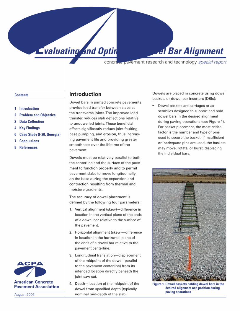
Dowels are placed in concrete using dowel baskets or dowel bar inserters (DBIs):
Dowel baskets are carriages or as-
semblies designed to support and hold
dowel bars in the desired alignment
during paving operations (see Figure 1).
For basket placement, the most critical
factor is the number and type of pins
used to secure the basket. If insufficient
or inadequate pins are used, the baskets
may move, rotate, or burst, displacing
the individual bars.
•
Contents
1 Introduction
2 ProblemandObjective
2 DataCollection
4 KeyFindings
6 CaseStudy(I-20,Georgia)
7 Conclusions
8 References
Figure1.Dowelbasketsholdingdowelbarsinthedesiredalignmentandpositionduringpavingoperations
American Concrete Pavement Association
August 2006
Concrete Pavement Research and Technology Special Report�
The potential adverse effects of poor dowel placement include poor load transfer efficiency and poor long-term faulting per-formance (if displaced toward the bottom of slab or out of joint), joint spalling (from excessive steel/concrete bearing stresses), and slab cracking (from joint lockup or restraint).
Most agencies have fairly strict tolerances on dowel placement accuracy, but those standards are unsubstantiated by field performance. In most cases, the manufac-turing tolerances for dowel baskets have been adopted directly as the dowel place-ment tolerances. This approach does not account for accuracy of placement relative to the grade or centerline. The accuracy of dowel placement achieved by contractors using typical methods is not well known.
Problem and ObjectiveImportant issues pertaining to dowel bar alignment in jointed concrete pavements include the following:
What quality of dowel bar alignment is
routinely achieved in typical concrete
pavement construction?
Is there a difference in quality of dowel
bar alignment when baskets are used
to place the dowel bars as compared to
those placed using DBIs?
What dowel placement tolerances are
needed to ensure good pavement per-
formance?
This publication addresses the first two questions based on a recent field measure-ment study (ARA 2005).
As part of the recent study, several in-service pavement sections were sur-veyed and tested for dowel bar alignment using the MIT Scan-2, a nondestructive testing device developed specifically for measuring dowel position and alignment. While the study provided valuable data related to maximum dowel misalignment, joint score, and basket vs. DBI construc-tion, a final determination of the specific dowel placement tolerance needed to ensure good pavement performance was beyond its scope.
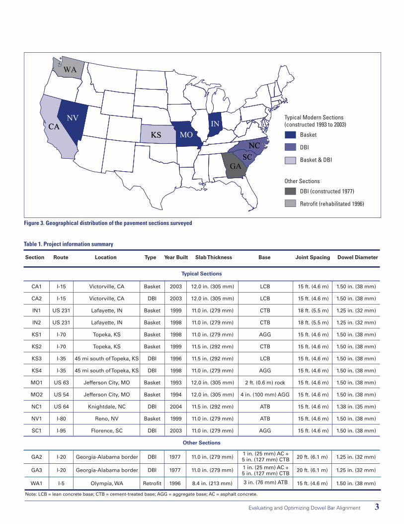
Data CollectionThirteen typical modern pavement sections (eight dowel basket sections and five DBI sections) from seven states, constructed between 1993 and 2003, were evaluated to quantify dowel alignment. In addition, two older DBI sections from Georgia, con-structed in 1977, and a dowel bar retrofit section in the state of Washington, reha-bilitated in 1996, were also evaluated. The geographic distribution of the projects surveyed is shown in Figure 3. Brief descriptions of these projects are summa-rized in Table 1.
•
•
•
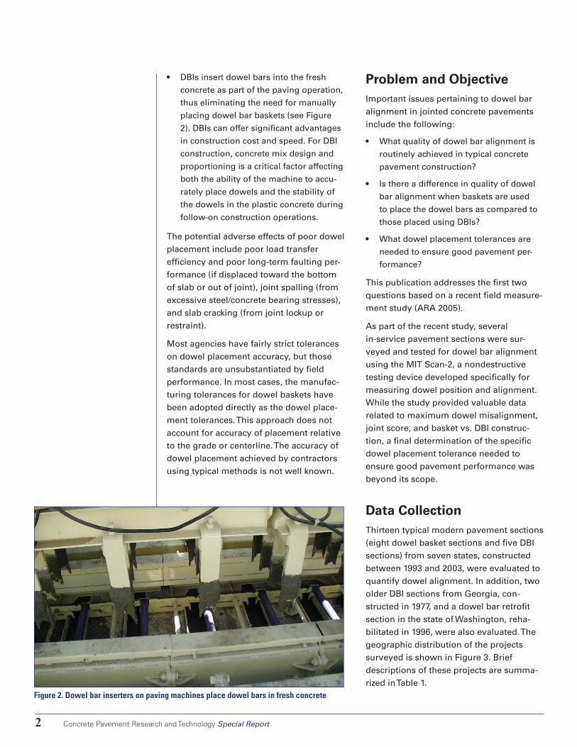
DBIs insert dowel bars into the fresh
concrete as part of the paving operation,
thus eliminating the need for manually
placing dowel bar baskets (see Figure
2). DBIs can offer significant advantages
in construction cost and speed. For DBI
construction, concrete mix design and
proportioning is a critical factor affecting
both the ability of the machine to accu-
rately place dowels and the stability of
the dowels in the plastic concrete during
follow-on construction operations.
•
Figure2.Dowelbarinsertersonpavingmachinesplacedowelbarsinfreshconcrete
Evaluating and Optimizing Dowel Bar Alignment �
WA
NV
MOKSIN
NCSC
CA
GA
CAKS
SC
WA
NV
MOKSIN
NCSC
CA
GA
Basket
DBI
Basket & DBI
DBI (constructed 1977)
Retrofit (rehabilitated 1996)
Typical Modern Sections(constructed 1993 to 2003)
Other Sections
Figure3.Geographicaldistributionofthepavementsectionssurveyed
Table1.Projectinformationsummary
Section Route Location Type Year Built Slab Thickness Base Joint Spacing Dowel Diameter
Typical Sections
CA1
CA2
IN1
IN2
KS1
KS2
KS3
KS4
MO1
MO2
NC1
NV1
SC1
I-15
I-15
US 231
US 231
I-70
I-70
I-35
I-35
US 63
US 54
US 64
I-80
I-95
Victorville, CA
Victorville, CA
Lafayette, IN
Lafayette, IN
Topeka, KS
Topeka, KS
45 mi south of Topeka, KS
45 mi south of Topeka, KS
Jefferson City, MO
Jefferson City, MO
Knightdale, NC
Reno, NV
Florence, SC
Basket
DBI
Basket
Basket
Basket
Basket
DBI
DBI
Basket
Basket
DBI
Basket
DBI
2003
2003
1999
1998
1998
1999
1996
1998
1993
1994
2004
1999
2003
12.0 in. (305 mm)
12.0 in. (305 mm)
11.0 in. (279 mm)
11.0 in. (279 mm)
11.0 in. (279 mm)
11.5 in. (292 mm)
11.5 in. (292 mm)
11.0 in. (279 mm)
12.0 in. (305 mm)
12.0 in. (305 mm)
11.5 in. (292 mm)
11.0 in. (279 mm)
11.0 in. (279 mm)
LCB
LCB
CTB
CTB
AGG
CTB
LCB
AGG
2 ft. (0.6 m) rock
4 in. (100 mm) AGG
ATB
ATB
AGG
15 ft. (4.6 m)
15 ft. (4.6 m)
18 ft. (5.5 m)
18 ft. (5.5 m)
15 ft. (4.6 m)
15 ft. (4.6 m)
15 ft. (4.6 m)
15 ft. (4.6 m)
15 ft. (4.6 m)
15 ft. (4.6 m)
15 ft. (4.6 m)
15 ft. (4.6 m)
15 ft. (4.6 m)
1.50 in. (38 mm)
1.50 in. (38 mm)
1.25 in. (32 mm)
1.25 in. (32 mm)
1.50 in. (38 mm)
1.50 in. (38 mm)
1.50 in. (38 mm)
1.50 in. (38 mm)
1.50 in. (38 mm)
1.50 in. (38 mm)
1.38 in. (35 mm)
1.50 in. (38 mm)
1.50 in. (38 mm)
Other Sections
GA2
GA3
WA1
I-20
I-20
I-5
Georgia-Alabama border
Georgia-Alabama border
Olympia, WA
DBI
DBI
Retrofit
1977
1977
1996
11.0 in. (279 mm)
11.0 in. (279 mm)
8.4 in. (213 mm)
1 in. (25 mm) AC +5 in. (127 mm) CTB1 in. (25 mm) AC +5 in. (127 mm) CTB
3 in. (76 mm) ATB
20 ft. (6.1 m)
20 ft. (6.1 m)
15 ft. (4.6 m)
1.25 in. (32 mm)
1.25 in. (32 mm)
1.50 in. (38 mm)
Note: LCB = lean concrete base; CTB = cement-treated base; AGG = aggregate base; AC = asphalt concrete.
Concrete Pavement Research and Technology Special Report�
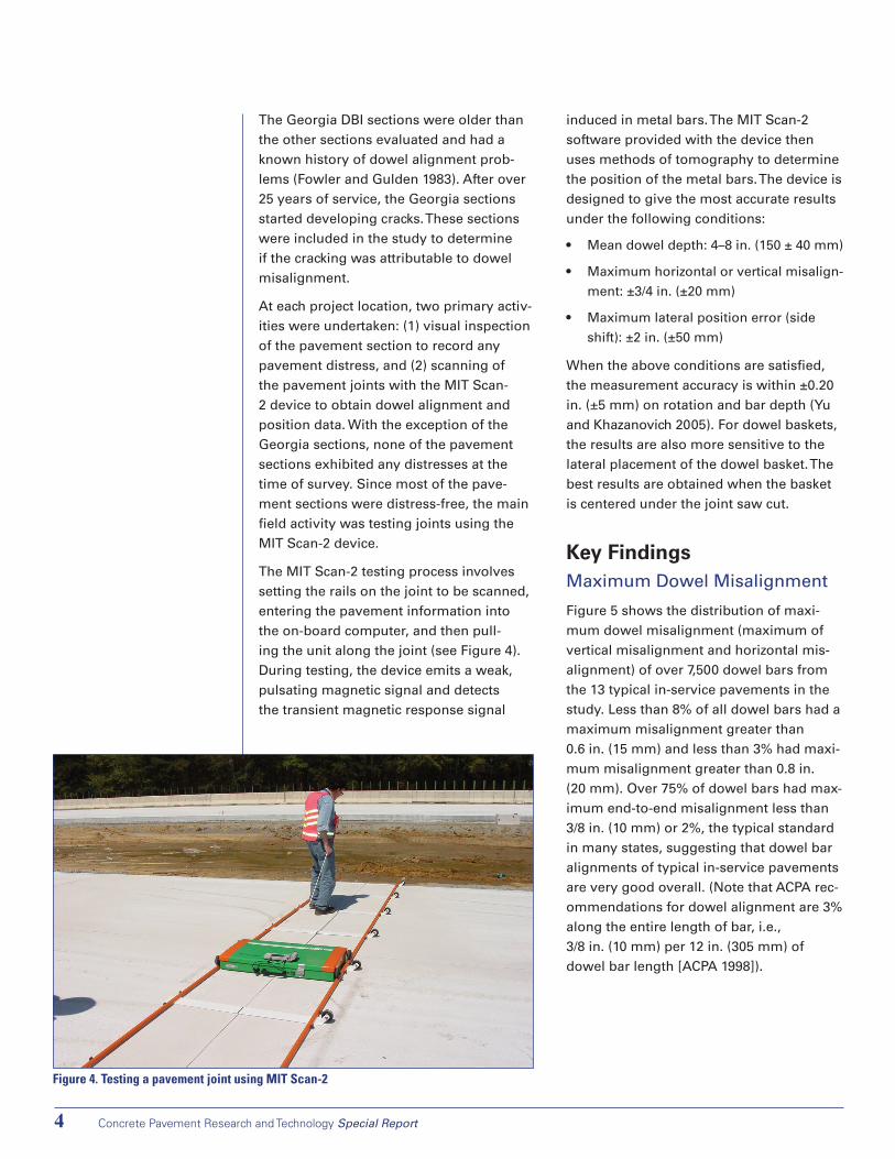
Figure4.TestingapavementjointusingMITScan-2
The Georgia DBI sections were older than the other sections evaluated and had a known history of dowel alignment prob-lems (Fowler and Gulden 1983). After over 25 years of service, the Georgia sections started developing cracks. These sections were included in the study to determine if the cracking was attributable to dowel misalignment.
At each project location, two primary activ-ities were undertaken: (1) visual inspection of the pavement section to record any pavement distress, and (2) scanning of the pavement joints with the MIT Scan-2 device to obtain dowel alignment and position data. With the exception of the Georgia sections, none of the pavement sections exhibited any distresses at the time of survey. Since most of the pave-ment sections were distress-free, the main field activity was testing joints using the MIT Scan-2 device.
The MIT Scan-2 testing process involves setting the rails on the joint to be scanned, entering the pavement information into the on-board computer, and then pull-ing the unit along the joint (see Figure 4). During testing, the device emits a weak, pulsating magnetic signal and detects the transient magnetic response signal
induced in metal bars. The MIT Scan-2 software provided with the device then uses methods of tomography to determine the position of the metal bars. The device is designed to give the most accurate results under the following conditions:
Mean dowel depth: 4–8 in. (150 ± 40 mm)
Maximum horizontal or vertical misalign-
ment: ±3/4 in. (±20 mm)
Maximum lateral position error (side
shift): ±2 in. (±50 mm)
When the above conditions are satisfied, the measurement accuracy is within ±0.20 in. (±5 mm) on rotation and bar depth (Yu and Khazanovich 2005). For dowel baskets, the results are also more sensitive to the lateral placement of the dowel basket. The best results are obtained when the basket is centered under the joint saw cut.
Key FindingsMaximum Dowel Misalignment
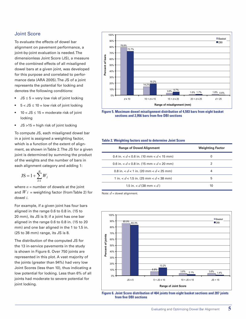
Figure 5 shows the distribution of maxi-mum dowel misalignment (maximum of vertical misalignment and horizontal mis-alignment) of over 7,500 dowel bars from the 13 typical in-service pavements in the study. Less than 8% of all dowel bars had a maximum misalignment greater than 0.6 in. (15 mm) and less than 3% had maxi-mum misalignment greater than 0.8 in. (20 mm). Over 75% of dowel bars had max-imum end-to-end misalignment less than 3/8 in. (10 mm) or 2%, the typical standard in many states, suggesting that dowel bar alignments of typical in-service pavements are very good overall. (Note that ACPA rec-ommendations for dowel alignment are 3% along the entire length of bar, i.e., 3/8 in. (10 mm) per 12 in. (305 mm) of dowel bar length [ACPA 1998]).
•
•
•
Evaluating and Optimizing Dowel Bar Alignment �
78.8%
14.2%
3.6% 1.6% 1.8%
72.7%
19.2%
5.7%1.7% 0.6%
0%
10%
20%
30%
40%
50%
60%
70%
80%
90%
100%
d ≤ 10 10 < d ≤ 15 15 < d ≤ 20 20 < d ≤ 25 d > 25
Range of misalignment (mm)P
erce
nt o
f bar
s
BasketDBI
Joint Score
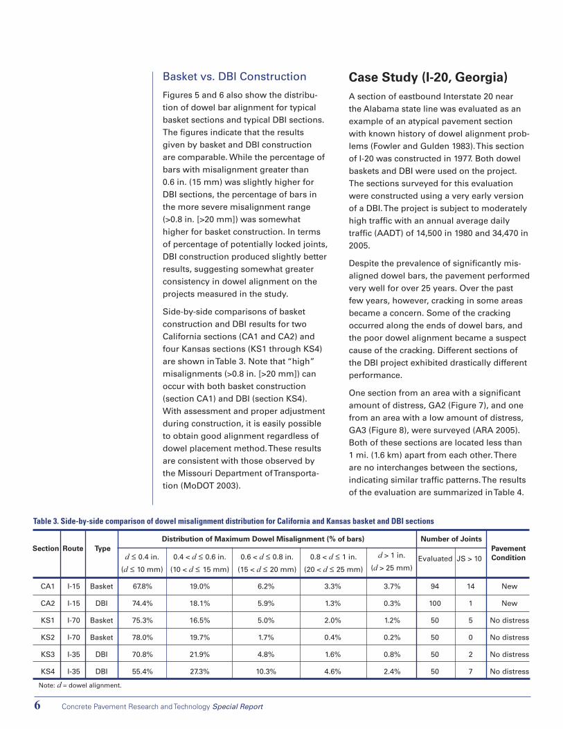
To evaluate the effects of dowel bar alignment on pavement performance, a joint-by-joint evaluation is needed. The dimensionless Joint Score (JS), a measure of the combined effects of all misaligned dowel bars at a given joint, was developed for this purpose and correlated to perfor-mance data (ARA 2005). The JS of a joint represents the potential for locking and denotes the following conditions:
JS ≤ 5 = very low risk of joint locking
5 < JS ≤ 10 = low risk of joint locking
10 < JS ≤ 15 = moderate risk of joint
locking
JS >15 = high risk of joint locking
To compute JS, each misaligned dowel bar in a joint is assigned a weighting factor, which is a function of the extent of align-ment, as shown in Table 2. The JS for a given joint is determined by summing the product of the weights and the number of bars in each alignment category and adding 1:
•
•
•
•
Figure5.Maximumdowelmisalignmentdistributionof4,593barsfromeightbasketsectionsand2,956barsfromfiveDBIsections
∑=
+=n
1iiW1JS
where n = number of dowels at the joint and W i = weighting factor (from Table 2) for dowel i.
For example, if a given joint has four bars aligned in the range 0.6 to 0.8 in. (15 to 20 mm), its JS is 9; if a joint has one bar aligned in the range 0.6 to 0.8 in. (15 to 20 mm) and one bar aligned in the 1 to 1.5 in. (25 to 38 mm) range, its JS is 8.
The distribution of the computed JS for the 13 in-service pavements in the study is shown in Figure 6. Over 750 joints are represented in this plot. A vast majority of the joints (greater than 94%) had very low Joint Scores (less than 10), thus indicating a low potential for locking. Less than 6% of all joints had moderate to severe potential for joint locking.
85.9%
6.8%3.6% 3.6%
83.3%
13.2%
2.1% 1.4%0%
10%
20%
30%
40%
50%
60%
70%
80%
90%
100%
JS ≤ 5 5 < JS ≤ 10 10 < JS ≤ 15 JS > 15
Range of Joint Score
Per
cent
of j
oint
s
BasketDBI
Figure6.JointScoredistributionof464jointsfromeightbasketsectionsand287jointsfromfiveDBIsections
Table2.WeightingfactorsusedtodetermineJointScore
Range of Dowel Alignment Weighting Factor
0.4 in. < d < 0.6 in. (10 mm < d < 15 mm)
0.6 in. < d < 0.8 in. (15 mm < d < 20 mm)
0.8 in. < d < 1 in. (20 mm < d < 25 mm)
1 in. < d < 1.5 in. (25 mm < d < 38 mm)
1.5 in. < d (38 mm < d )
0
2
4
5
10
Note: d = dowel alignment.
Concrete Pavement Research and Technology Special Report�
Basket vs. DBI Construction
Figures 5 and 6 also show the distribu-tion of dowel bar alignment for typical basket sections and typical DBI sections. The figures indicate that the results given by basket and DBI construction are comparable. While the percentage of bars with misalignment greater than 0.6 in. (15 mm) was slightly higher for DBI sections, the percentage of bars in the more severe misalignment range (>0.8 in. [>20 mm]) was somewhat higher for basket construction. In terms of percentage of potentially locked joints, DBI construction produced slightly better results, suggesting somewhat greater consistency in dowel alignment on the projects measured in the study.
Side-by-side comparisons of basket construction and DBI results for two California sections (CA1 and CA2) and four Kansas sections (KS1 through KS4) are shown in Table 3. Note that “high” misalignments (>0.8 in. [>20 mm]) can occur with both basket construction (section CA1) and DBI (section KS4). With assessment and proper adjustment during construction, it is easily possible to obtain good alignment regardless of dowel placement method. These results are consistent with those observed by the Missouri Department of Transporta-tion (MoDOT 2003).
Case Study (I-20, Georgia)A section of eastbound Interstate 20 near the Alabama state line was evaluated as an example of an atypical pavement section with known history of dowel alignment prob-lems (Fowler and Gulden 1983). This section of I-20 was constructed in 1977. Both dowel baskets and DBI were used on the project. The sections surveyed for this evaluation were constructed using a very early version of a DBI. The project is subject to moderately high traffic with an annual average daily traffic (AADT) of 14,500 in 1980 and 34,470 in 2005.
Despite the prevalence of significantly mis-aligned dowel bars, the pavement performed very well for over 25 years. Over the past few years, however, cracking in some areas became a concern. Some of the cracking occurred along the ends of dowel bars, and the poor dowel alignment became a suspect cause of the cracking. Different sections of the DBI project exhibited drastically different performance.
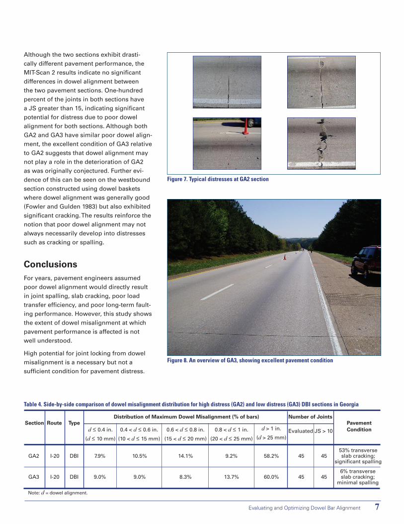
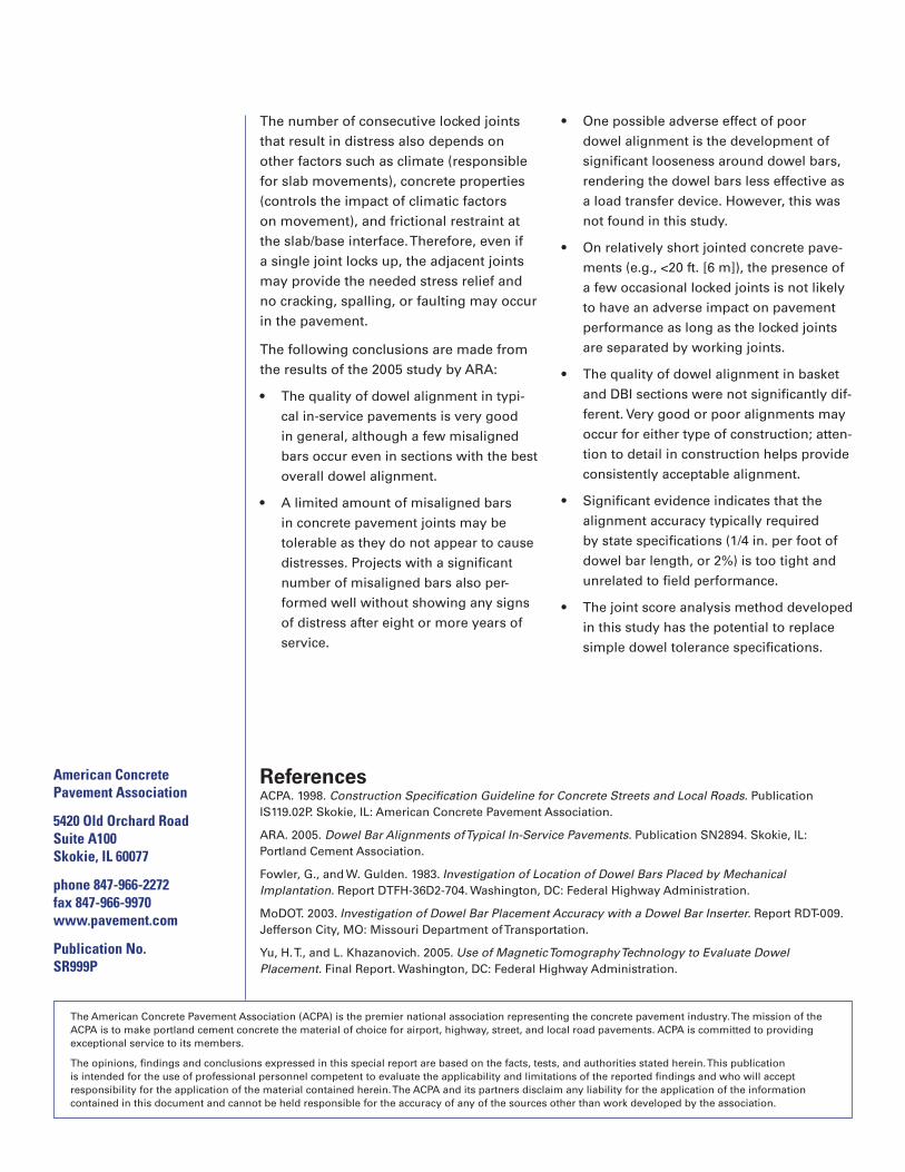
One section from an area with a significant amount of distress, GA2 (Figure 7), and one from an area with a low amount of distress, GA3 (Figure 8), were surveyed (ARA 2005). Both of these sections are located less than 1 mi. (1.6 km) apart from each other. There are no interchanges between the sections, indicating similar traffic patterns. The results of the evaluation are summarized in Table 4.
Table3.Side-by-sidecomparisonofdowelmisalignmentdistributionforCaliforniaandKansasbasketandDBIsections
Distribution of Maximum Dowel Misalignment (% of bars) Number of Joints
Evaluated JS > 10Section Route Type
d ≤ 0.4 in.
(d ≤ 10 mm)
0.4 < d ≤ 0.6 in.
(10 < d ≤ 15 mm)
0.6 < d ≤ 0.8 in.
(15 < d ≤ 20 mm)
0.8 < d ≤ 1 in.
(20 < d ≤ 25 mm)
d > 1 in.
(d > 25 mm)
Pavement Condition
CA1
CA2
KS1
KS2
KS3
KS4
I-15
I-15
I-70
I-70
I-35
I-35
Basket
DBI
Basket
Basket
DBI
DBI
67.8%
74.4%
75.3%
78.0%
70.8%
55.4%
19.0%
18.1%
16.5%
19.7%
21.9%
27.3%
6.2%
5.9%
5.0%
1.7%
4.8%
10.3%
3.3%
1.3%
2.0%
0.4%
1.6%
4.6%
3.7%
0.3%
1.2%
0.2%
0.8%
2.4%
94
100
50
50
50
50
14
1
5
0
2
7
New
New
No distress
No distress
No distress
No distress
Note: d = dowel alignment.
Evaluating and Optimizing Dowel Bar Alignment �
Figure7.TypicaldistressesatGA2section
Figure8.AnoverviewofGA3,showingexcellentpavementcondition
Although the two sections exhibit drasti-cally different pavement performance, the MIT-Scan 2 results indicate no significant differences in dowel alignment between the two pavement sections. One-hundred percent of the joints in both sections have a JS greater than 15, indicating significant potential for distress due to poor dowel alignment for both sections. Although both GA2 and GA3 have similar poor dowel align-ment, the excellent condition of GA3 relative to GA2 suggests that dowel alignment may not play a role in the deterioration of GA2 as was originally conjectured. Further evi-dence of this can be seen on the westbound section constructed using dowel baskets where dowel alignment was generally good (Fowler and Gulden 1983) but also exhibited significant cracking. The results reinforce the notion that poor dowel alignment may not always necessarily develop into distresses such as cracking or spalling.
ConclusionsFor years, pavement engineers assumed poor dowel alignment would directly result in joint spalling, slab cracking, poor load transfer efficiency, and poor long-term fault-ing performance. However, this study shows the extent of dowel misalignment at which pavement performance is affected is not well understood.
High potential for joint locking from dowel misalignment is a necessary but not a sufficient condition for pavement distress.
Table4.Side-by-sidecomparisonofdowelmisalignmentdistributionforhighdistress(GA2)andlowdistress(GA3)DBIsectionsinGeorgia
Distribution of Maximum Dowel Misalignment (% of bars) Number of Joints
Evaluated JS > 10
Section Route Typed ≤ 0.4 in.
(d ≤ 10 mm)
0.4 < d ≤ 0.6 in.
(10 < d ≤ 15 mm)
0.6 < d ≤ 0.8 in.
(15 < d ≤ 20 mm)
0.8 < d ≤ 1 in.
(20 < d ≤ 25 mm)
d > 1 in.
(d > 25 mm)
Pavement Condition
GA2
GA3
I-20
I-20
DBI
DBI
7.9%
9.0%
10.5%
9.0%
14.1%
8.3%
9.2%
13.7%
58.2%
60.0%
45
45
45
456% transverse slab cracking;
minimal spalling
53% transverse slab cracking;
significant spalling
Note: d = dowel alignment.
The number of consecutive locked joints that result in distress also depends on other factors such as climate (responsible for slab movements), concrete properties (controls the impact of climatic factors on movement), and frictional restraint at the slab/base interface. Therefore, even if a single joint locks up, the adjacent joints may provide the needed stress relief and no cracking, spalling, or faulting may occur in the pavement.
The following conclusions are made from the results of the 2005 study by ARA:
The quality of dowel alignment in typi-
cal in-service pavements is very good
in general, although a few misaligned
bars occur even in sections with the best
overall dowel alignment.
A limited amount of misaligned bars
in concrete pavement joints may be
tolerable as they do not appear to cause
distresses. Projects with a significant
number of misaligned bars also per-
formed well without showing any signs
of distress after eight or more years of
service.
•
•
One possible adverse effect of poor
dowel alignment is the development of
significant looseness around dowel bars,
rendering the dowel bars less effective as
a load transfer device. However, this was
not found in this study.
On relatively short jointed concrete pave-
ments (e.g., <20 ft. [6 m]), the presence of
a few occasional locked joints is not likely
to have an adverse impact on pavement
performance as long as the locked joints
are separated by working joints.
The quality of dowel alignment in basket
and DBI sections were not significantly dif-
ferent. Very good or poor alignments may
occur for either type of construction; atten-
tion to detail in construction helps provide
consistently acceptable alignment.
Significant evidence indicates that the
alignment accuracy typically required
by state specifications (1/4 in. per foot of
dowel bar length, or 2%) is too tight and
unrelated to field performance.
The joint score analysis method developed
in this study has the potential to replace
simple dowel tolerance specifications.
•
•
•
•
•
ReferencesACPA. 1998. Construction Specification Guideline for Concrete Streets and Local Roads. Publication IS119.02P. Skokie, IL: American Concrete Pavement Association.
ARA. 2005. Dowel Bar Alignments of Typical In-Service Pavements. Publication SN2894. Skokie, IL: Portland Cement Association.
Fowler, G., and W. Gulden. 1983. Investigation of Location of Dowel Bars Placed by Mechanical Implantation. Report DTFH-36D2-704. Washington, DC: Federal Highway Administration.
MoDOT. 2003. Investigation of Dowel Bar Placement Accuracy with a Dowel Bar Inserter. Report RDT-009. Jefferson City, MO: Missouri Department of Transportation.
Yu, H. T., and L. Khazanovich. 2005. Use of Magnetic Tomography Technology to Evaluate Dowel Placement. Final Report. Washington, DC: Federal Highway Administration.
AmericanConcretePavementAssociation
5420OldOrchardRoadSuiteA100Skokie,IL60077
phone847-966-2272fax847-966-9970www.pavement.com
PublicationNo.SR999P
The American Concrete Pavement Association (ACPA) is the premier national association representing the concrete pavement industry. The mission of the ACPA is to make portland cement concrete the material of choice for airport, highway, street, and local road pavements. ACPA is committed to providing exceptional service to its members.
The opinions, findings and conclusions expressed in this special report are based on the facts, tests, and authorities stated herein. This publication is intended for the use of professional personnel competent to evaluate the applicability and limitations of the reported findings and who will accept responsibility for the application of the material contained herein. The ACPA and its partners disclaim any liability for the application of the information contained in this document and cannot be held responsible for the accuracy of any of the sources other than work developed by the association.