euroradio fis · 3.1.1.2 this fis is applicable for both circuit switched (cs) and packet switched...
TRANSCRIPT

© This document has been developed and released by UNISIG
SUBSET-037
v3.2.0
EuroRadio FIS Page 1/126
ERTMS/ETCS
EuroRadio FIS
REF : SUBSET-037
ISSUE : 3.2.0
DATE: 17 December 2015
Company Technical Approval Management approval
ALSTOM
ANSALDO
AZD
BOMBARDIER
CAF
SIEMENS
THALES

© This document has been developed and released by UNISIG
SUBSET-037
v3.2.0
EuroRadio FIS Page 2/126
1 MODIFICATION HISTORY
Issue Number
Date
Section Number Modification / Description Author
2.0.0
30-March- 2000
Final issue to ECSAG U.D. (ed)
2.1.0
23-November-2001
All Revision LK
2.1.7 Version with revision marks LK
2.2.0 Final issue after revision LK
2.2.1 3.4, 5.2, 5.3, 7.1.2,
7.2.2, 7.2.4, 7.2.5,
7.3.2, 8.2.3, 8.2.4,
8.3.1, Annex A, B.1,
C.1
Review comments of Unisig
super group inserted
LK
2.2.1+ 7.2.5.3.6, 7.2.5.3.7 State table updated
(state DATA, event DT
SaPDU -> splitting in to
Conditions Pre 5 and Pre 6;
state AR SaPDU, event AR
SaPDU -> DI SaPDU
added)
TS
2.2.1.++ 7.3.2.2.1 Table 23 Bit numbering
changed
TS
2.2.2r 3.4.1.1, 7.2.5.3.6 Editorial changes LK
2.2.2 - Clean version LK
2.2.3 3., 3.1.1.5, 3.1.16, 3.3,
3.4.1, 7.2.2.2.1.4,
7.2.5.3.7, 8.2.3.1.2,
8.3.1.14
Review comments of GSM-
R users group inserted,
Clarifications, references
updated
LK
2.2.4 - Clean version LK
2.2.5 - Formal release LK
2.2.5.revA 3.4, 5.2, 5.7, 7.3.3,
8.2.2, 8.2.4, 8.2.5,
8.3.1
Proposed changes
according to LOP v 020
LK
2.2.5.revB 3.4, 5.2, 5.7, 7.3.3,
8.2.2, 8.2.3, 8.2.4,
8.2.5, 8.3.1, B.1, B.5
Changes of Neu-Ulm
meeting
TS+LK

© This document has been developed and released by UNISIG
SUBSET-037
v3.2.0
EuroRadio FIS Page 3/126
2.2.5.revC 5.2.1.7, 7.3.3.5.4,
8.2.2.6, 8.2.2.9,
8.2.3.2.3, 8.3.1.1,
8.3.2.2.1, 8.3.3.1.2,
B.1.1.1.9
Changes of Berlin meeting LK
2.2.5.revD 3.4.1, 8.2.5, 8.3.1,
8.3.3, Annex A
Changes of Edinburgh
meeting
TS+LK
2.2.5.revE 3.4, 4.1.1.1, 7.2.2.2.2,
7.2.4.2, 7.3.2, 8.2.2,
8.2.4, Annex D, Annex
E
Changes of Stockholm
meeting and email
discussion
LK
2.2.5.revF 3.3, 3.4, 7.2.2, 7.2.4,
7.3.2, 8.2.2, 8.2.5,
8.3.1, AnnexD,
AnnexE
Changes of Paris meeting
and email discussion
WM+LK
2.2.5.revG 4.1.1.10, 5.71.4,
7.3.3.5.6, 8.2.3.2.5,
8.2.5, 8.2.7, E.2
Changes of Zürich meeting PL+LK
2.3.0 AnnexE.1, Tables
31, 34, 35
Formal release JH
2.3.1 incorporate CR825;
insert new Annexes
E and F; rename old
Annex E to Annex G
wg
2.3.2 All; incorporate
CR380, CR814,
CR970, CR1018;
Page setup, layout
and references; All §
Changes from meeting July
2011 and review comments
JM/XM
2.3.3-5 All; editorial Internal wg reviews JH
2.3.6 - Formal release ER WG
2.3.7 CR1018
CR1135
ER WG
XM
2.3.8 - Internal WG review ER WG
2.3.9 - Update according SG
comments on CR1018
CR1137
XM
3.0.0 5.8, 7.2.2, 7.2.3,
Table 29, B.7,
deleted annex H.
Editorial
Baseline 3 release version ER WG

© This document has been developed and released by UNISIG
SUBSET-037
v3.2.0
EuroRadio FIS Page 4/126
3.0.1 Table 11 CR1151 JM
3.0.2 Front page Baseline 3 1st maintenance
pre-release version
PP
3.1.0 - Baseline 3 1st maintenance
release version
PP
3.1.1 CR741 (Packet data
transmission for ETCS)
ER WG
3.1.2 Updated with review
comments
ER WG
3.1.3 Updated with TCP
parameters and DNS txt
field for comments of EUG
ER WG
3.1.4 Updated with comments of
the EUG and input from
EIRENE.
CR1262.
ER WG
3.1.5 Updated with comments,
multiplexing for mobile
interface, KMS
ER WG
3.1.6 Updated with comments in
Unisig_B3R2_documents-
consolidated review sheet
ER WG
3.2.0 - Baseline 3 2nd release
version
PP

© This document has been developed and released by UNISIG
SUBSET-037
v3.2.0
EuroRadio FIS Page 5/126
2 TABLE OF CONTENTS
1 MODIFICATION HISTORY ............................................................................................................... 2
2 TABLE OF CONTENTS .................................................................................................................... 5
3 GENERAL ASPECTS ...................................................................................................................... 8
3.1 Scope................................................................................................................................ 8
3.2 Acronyms and abbreviations ............................................................................................. 9
3.3 Definitions ....................................................................................................................... 11
3.4 References ..................................................................................................................... 13
4 REFERENCE ARCHITECTURE ....................................................................................................... 16
5 INTERFACE TO SAFE SERVICES .................................................................................................... 20
5.1 General ........................................................................................................................... 20
5.2 Service primitives for safe connection set-up .................................................................. 20
5.3 Service primitives for safe data transfer .......................................................................... 23
5.4 Service primitives for connection release ........................................................................ 23
5.5 Service primitives for error reporting ............................................................................... 25
5.6 Service primitives for high priority data ............................................................................ 25
5.7 Service primitives for mobile network registration ............................................................ 26
5.8 Service primitives for Permitted Mobile Networks ............................................................ 27
6 INTERFACE TO THE MOBILE NETWORK .......................................................................................... 30
7 SAFE FUNCTIONAL MODULE ........................................................................................................ 31
7.1 Service definition ............................................................................................................. 31
7.1.2 Model of the safe services........................................................................................ 31
7.1.3 Safe connection set-up ............................................................................................ 32
7.1.4 Safe data transfer .................................................................................................... 32
7.1.5 Release of safe connection ...................................................................................... 32
7.1.6 Error reporting .......................................................................................................... 33
7.1.7 Service for high priority data ..................................................................................... 33
7.2 Safety protocol ................................................................................................................ 34
7.2.1 Introduction .............................................................................................................. 34
7.2.2 Generic MAC-Calculation ......................................................................................... 34
7.2.3 Functions of the safety layer .................................................................................... 34
7.2.4 Time sequences ....................................................................................................... 41
7.2.5 Structure and encoding of safety PDUs .................................................................... 45
7.2.6 State table ................................................................................................................ 49
7.3 Safety Protocol Management .......................................................................................... 54
7.3.1 Functions of the Safety Protocol Management ......................................................... 54

© This document has been developed and released by UNISIG
SUBSET-037
v3.2.0
EuroRadio FIS Page 6/126
7.3.2 Configuration Management ...................................................................................... 55
7.3.3 Supervision and Diagnostics .................................................................................... 56
8 COMMUNICATION FUNCTIONAL MODULE ...................................................................................... 60
8.1 Service definition ............................................................................................................. 60
8.1.1 Model of communication services ............................................................................ 60
8.1.2 Connection establishment ........................................................................................ 61
8.1.3 Data transfer ............................................................................................................ 61
8.1.4 Connection release .................................................................................................. 62
8.1.5 High Priority Data (CS mode only) ........................................................................... 62
8.1.6 Quality of Service (only for CS mode) ...................................................................... 62
8.1.7 Allocation Function ................................................................................................... 63
8.2 Communication protocols for CS ..................................................................................... 63
8.2.1 Introduction .............................................................................................................. 63
8.2.2 Data Link Layer ........................................................................................................ 63
8.2.3 Network Layer .......................................................................................................... 65
8.2.4 Transport Layer ........................................................................................................ 66
8.2.5 Applicability conditions of [ITU-T X.224] ................................................................... 71
8.2.6 Time sequences ....................................................................................................... 75
8.2.7 Relationships of PDUs and SDUs ............................................................................ 77
8.3 Communication protocols for PS ..................................................................................... 80
8.3.1 Introduction .............................................................................................................. 80
8.3.2 Adaptation Layer Entity (ALE) .................................................................................. 80
8.3.3 TCP Layer ................................................................................................................ 82
8.3.4 Network Layer .......................................................................................................... 84
8.3.5 Data Link Layer ........................................................................................................ 84
8.3.6 Time sequences ....................................................................................................... 84
8.3.7 Relationship of PDUs ............................................................................................... 89
8.4 Management of Communication Functional Module ........................................................ 90
8.4.1 Call and ID-Management ......................................................................................... 90
8.4.2 Configuration management ...................................................................................... 96
8.4.3 Supervision / Diagnostics ......................................................................................... 98
8.5 Resource Management for on-board IP communication applications ............................ 100
ANNEX A. (NORMATIVE) ASSUMPTIONS PLACED ON THE ATP APPLICATION ................................. 102
ANNEX B. (OPTION) INTERFACE TO COMMUNICATIONS SERVICES ............................................... 103
B.2. Service primitives for connection establishment......................................................... 103
B.3. Service primitives for data transfer............................................................................. 104
B.4. Service primitives for HP data transfer ....................................................................... 105

© This document has been developed and released by UNISIG
SUBSET-037
v3.2.0
EuroRadio FIS Page 7/126
B.5. Service primitives for connection release ................................................................... 105
B.6. Service primitives for network registration.................................................................. 106
B.7. Service primitives for permitted networks................................................................... 107
ANNEX C. (OPTION) SAFETY PROTOCOL MANAGEMENT ............................................................. 108
ANNEX D. (INFORMATIVE) APPLICABILITY CONDITIONS OF ISO/IEC 7776 (1995) ......................... 109
ANNEX E. (INFORMATIVE) CBC-MAC CALCULATION.................................................................. 114
ANNEX F. (INFORMATIVE) HDLC WINDOW SIZE ........................................................................ 117
ANNEX G. (INFORMATIVE) HOW TO CREATE THE LIST OF PERMITTED NETWORKS – EXAMPLE ........ 118
G.1. Read allowed networks and their alphanumeric name from the SIM card .................. 118
G.2. Build list of permitted networks .................................................................................. 120
ANNEX H. (INFORMATIVE) GSM-R PROCEDURES FOR PS MODE ................................................ 122
H.1. Procedures ................................................................................................................ 122
H.2. GPRS Attach ............................................................................................................. 122
H.3. PDP Context Activation ............................................................................................. 122
ANNEX I. (INFORMATIVE) CS-PS MODE SELECTION SCHEME ..................................................... 123

© This document has been developed and released by UNISIG
SUBSET-037
v3.2.0
EuroRadio FIS Page 8/126
3 GENERAL ASPECTS
3.1 Scope
3.1.1.1 This FIS is applicable to radio communication systems providing communication services
for safety-related application processes using open networks. It specifies for
ERTMS/ETCS the Radio System Interoperability for message exchange between on-
board and trackside equipment in respect to safety-related application processes, like
Automatic Train Protection of ETCS level 2/3. Additionally, it specifies for ETCS level 1
the optional message exchange between on-board equipment and radio in-fill unit.
3.1.1.2 This FIS is applicable for both Circuit Switched (CS) and Packet Switched (PS) data
transmission.
3.1.1.3 Optionally, this FIS is applicable also to non-safety related application processes using
the services of the radio communication subsystem for communication purposes.
3.1.1.4 In particular this FIS does not define:
The application functionality and application information flow.
The open networks used.
The physical architecture of the radio communication subsystem.
3.1.1.5 Within the scope of this document, the terms ”Radio Communication System (RCS)” and
EuroRadio system are used synonymously.
3.1.1.6 Currently, the version handling fixed for ERTMS/ETCS is as follows:
There is one version of CFM only.
There is one version of SFM only.
3.1.1.7 The CS-PS dual stack defined in this document is compatible with the CS only stack of
previous versions of this specification. Even if the network is PS enabled, the trackside is
allowed to only support CS mode.
3.1.1.8 Version upgrade for enhanced EuroRadio CFM and SFM, if any, will follow the principle
as defined in [Subset-026]:
The on-board CFM and SFM may operate with several of its versions.
The on-board CFM and SFM will decide whether it can use the protocol data units
(PDUs) received from trackside.
This version check does not restrict negotiation of connection features by means of
QoS class (CFM) or safety feature (SFM).
3.1.1.9 The CS-PS dual stack defined in this document provides only train initiated connection
establishment in case of train - trackside communications.

© This document has been developed and released by UNISIG
SUBSET-037
v3.2.0
EuroRadio FIS Page 9/126
3.2 Acronyms and abbreviations
3.2.1.1 For general ERTMS/ETCS terms, definitions and abbreviations refer to [Subset-023]. New
terms and abbreviations relevant and used in this FIS are specified here.
AR Authentication Response
AU1 First Authentication message
AU2 Second Authentication message
AU3 Third Authentication message
BAC Balanced Asynchronous Class
Bm Full-rate traffic channel
BS Bearer Service
CEPID Connection EndPoint IDentifier
CFM Communication Functional Module
CS Circuit Switched
CSPDN Circuit Switched Public Data Network
DA Destination Address
DCE Data Communication Equipment
DES Data Encryption Standard
DF Direction Flag
DI Disconnect
Dm Control Channel
DT Data
DTE Data Terminal Equipment
EF Elementary File (SIM Card)
eMLPP Enhanced Multi-Level Precedence and Pre-emption
ETS European Telecommunication Standard
ETY ETCS ID type field in a SaPDU
FEC Forward Error Correction
FRMR FRaMe Reject
HDLC High level Data Link Control
HP High Priority
ID Identity
IEC International Electrotechnical Commission
ISDN Integrated Services Digital Network
ITU International Telecommunication Union
KAB Authentication Key (same as KMAC)

© This document has been developed and released by UNISIG
SUBSET-037
v3.2.0
EuroRadio FIS Page 10/126
KS Session Key (same as KSMAC)
KSMAC Session Key
LAPB Link Access Protocol Balanced
m message
MA Management
MNID MNID list is a list of Mobile Network IDs.
MT Mobile Termination
MTI Message Type Identifier
NPDU Network Protocol Data Unit
NSAP Network Service Access Point
NSDU Network Service Data Unit
NT Network Termination
O&M Operation and Maintenance
OSI Open System Interconnection
PDN Packet Data Network
PDU Protocol Data Unit
PDP Packet Data Protocol
PPP Point to Point Protocol
PS Packet Switched
PSD Packet Switched Data
PSTN Public Switched Telephone Network
QoS Quality of Service
RCS Radio Communication System also used as synonym for EuroRadio system
RP ResPonse
RQ ReQuest
RTO Retransmission TimeOut
SA Source Address
SABME Set Asynchronous Balanced Mode Extended
SaCEPID Safe Connection EndPoint IDentifier
SaF Safety Features
SAP Service Access Point
SaPDU Safety Protocol Data Unit
SaS Safety Service
SaSAP Safety Service Access Point
SaSDU Safety Service Data Unit
SaUD Safety User Data

© This document has been developed and released by UNISIG
SUBSET-037
v3.2.0
EuroRadio FIS Page 11/126
SFM Safe Functional Module
SREJ Selective REJect
TC Transport Connection
TCEPID Transport Connection EndPoint IDentifier
TCH Traffic Channel
TP Transport Protocol
TP2 Transport Protocol Class 2
TPDU Transport Protocol Data Unit
TS Transport Service
TSAP Transport Service Access Point
TSDU Transport Service Data Unit
UA Unnumbered Acknowledge
UI Unnumbered Information (HDLC frame)
X Mandatory parameter
X(U) Use of this parameter is a user option
X(D) Use of this parameter is a user option. If not provided, a default value will be
used.
3.3 Definitions
3.3.1.1 For general ERTMS/ETCS terms, definitions and abbreviations refer to [Subset-023]. New
definitions relevant and used in this FIS are specified here.
Mandatory feature: The feature has to be provided by on-board and/or trackside equipment
where interoperability is required.
Optional feature/Option: The feature might be provided or not. If provided, it has to be provided
as specified. Optional features are not required. Interoperability between EuroRadio systems
providing and not providing the optional feature has to be guaranteed. Otherwise, the option has to
be deactivated.
National Add-on:
The feature is a matter of national railway specification. Interoperability must not be influenced.
CS MODE
Circuit switched transmission mode uses a dedicated end-to-end transmission resource for each
logical connection.
DATA ENCRYPTION STANDARD (DES)
A block cipher published in 1977 by the NBS as a US government norm. DES has been renamed
Data Encryption Algorithm (DEA) during its adoption as an ANSI standard ([ANSI X3.92], 1981).

© This document has been developed and released by UNISIG
SUBSET-037
v3.2.0
EuroRadio FIS Page 12/126
DES KEY
A cryptographic key of length 64 bits, where each eighth bit is an odd parity bit, as defined in [ANSI
X3.92], 1981. Because of this structure, the effective key length is 56 bits.
DELETION (of a message)
An attack in which a message is erased from the stream of messages.
FORM FIT FUNCTIONAL INTERFACE SPECIFICATION (FFFIS)
A FFFIS is the complete definition of an interface between functional or physical entities.
The FFFIS includes:
- FIS,
- Electrical characteristics related to data,
- communication protocol1,
- plug.
The FFFIS guarantees the interoperability but not the exchangeability of physical entities.
FUNCTIONAL INTERFACES SPECIFICATION (FIS)
A FIS specifies the link between functional modules or between physical entities by:
- The required external data flow,
- The required data characteristics,
- The data range and resolution requirements.
FUNCTIONAL MODULE
Set of functions contributing to realize the same global task.
INSERTION (of a new message)
An attack in which a new message is being implanted into the stream of messages.
MESSAGE AUTHENTICATION CODE (MAC)
An authenticator which is sent with a message to enable the receiver to detect alterations made to
the message since it left the sender and to verify that the source of the message is as claimed. The
MAC is a function of the whole message and a secret key.
MODIFICATION (of a message)
Any unauthorised change of any part of a message.
PADDING
The information used to fill the unused part of a message to fill the block size.
PS MODE
Packet switched transmission mode shares radio transmission resources between several logical
connections.
PS SERVICE SETUP
GPRS attach followed by PDP context activation, as described in ANNEX H.
1Note that 'Communication protocol' is used with different meanings in the EuroRadio FIS and FFFIS: In the FIS a communication protocol is a protocol between peer entities within different End Systems connected by a network. In the FFFIS a communication protocol is a protocol between functional modules or physical entities located in the same End System.

© This document has been developed and released by UNISIG
SUBSET-037
v3.2.0
EuroRadio FIS Page 13/126
PS STATUS
Status of the PS service setup: it’s successful or OK only if PS service setup is successful.
RADIO COMMUNICATION SYSTEM
A radio transmission system providing data communication services via open networks. It can be
completed by an safety related transmission system to ensure safe data transmission.
REPETITION/REPLAY
An attack in which a message is stored and re-transmitted later.
TRANSMISSION MODE TABLE
The Transmission mode table contains the transmission mode for each known ETCS ID (i.e. RBC).
TRIPLE-KEY
Term used for three concatenated DES-keys, i.e. a length of 192 bits. In this specification, KMAC
and KSMAC are both triple-keys.
3.4 References
3.4.1.1 This FIS incorporates by dated or undated references, provisions from other publications.
The relevant parts of these normative references are cited at the appropriate place in the
text and the publications are listed hereafter. For dated references, subsequent
amendments to or revisions of any of these publications apply to this FIS only when
incorporated in it by amendment or revision. For undated references the latest edition of
the publication referred to applies.
ANSI X3.92 12.80 American National Standard Data Encryption Algorithm
EIRENE FRS EIRENE Project Team. Functional Requirement Specification.
EIRENE SRS EIRENE Project Team. System Requirement Specification.
EN 300924 Enhanced Multi-Level Precedence and Pre-emption Service
(eMLPP) Stage 1 (GSM 02.6722.067)
EN 300938 MS - BSS interface; Data link layer specification (GSM
04.0644.006)
EN 300940 Mobile radio interface; Layer 3 specification (GSM 04.0824.008)
EN 301 515 Global System for Mobile Communication (GSM);
Requirements for GSM operation on railways
EN 50159 09.10 Safety-Related Communication in Transmission Systems
ETS 300011 1992 ISDN; Primary rate user-network interface; Layer 1 specification
and test principles
ETS 300102-1 1990 ISDN; User-network interface layer 3; Specification for basic
call control
ETS 300125 1991 ISDN; User-network interface data link layer specifications
EuroRadio FFFIS UIC ERTMS/GSM-R Unisig; EuroRadio Interface Group;
Radio Transmission FFFIS for EuroRadio; A11T6001
FIS LDA Morane FIS for Location-Dependent Addressing F12T6001
ISO/IEC 3309 12.93 HDLC procedures; Frame structure
ISO/IEC 4335 12.93 HDLC procedures; Elements of Procedures

© This document has been developed and released by UNISIG
SUBSET-037
v3.2.0
EuroRadio FIS Page 14/126
ISO/IEC 7776 07.95 Description of the X.25 LAPB-compatible DTE data link
procedure
ISO/IEC 7809 12.93 HDLC procedures; Classes of Procedures
ISO/IEC 9797-1 12.99 Information technology - Security techniques - Messages
Authentication Codes (MACs) - Part 1: Mechanisms using a
block cipher
ITU-T E.212 11.98 The international identification plan for mobile terminals and
mobile users
ITU-T T.70 03.93 Network-independent basic transport service for telematic
services
ITU-T T.90 01.92 Characteristics and protocols for terminals for telematic
services in ISDN
ITU-T X.214 11.93 Information Technology - Open System Interconnection -
Transport service definition
ITU-T X.224 11.93 Protocol for providing the OSI connection-mode transport
service
N-9018 UIC - GSM-R Network Codes
RFC 1034 Domain Names – Concepts and Facilities
RFC 1035 Domain Names – Implementation and Specification
RFC 2018 TCP Selective Acknowledgment Options
RFC 2883 An Extension to the Selective Acknowledgement (SACK) Option for TCP.
RFC 5482 TCP User Timeout Option
RFC 5682 Forward RTO-Recovery
RFC 791 Internet Protocol
RFC 793 Transmission Control Protocol
RFC 896 Congestion Control in IP/TCP Internetwork
RFC1122 Requirements for Internet Hosts -- Communication Layers.
RFC1323 TCP Extensions for High Performance
SIM FFFIS MORANE SIM FFFIS for GSM-R SIM cards
P38T9001
Subset-023 Glossary of Terms and Abbreviations
Subset-026 System Requirements Specification
Subset-092-1 ERTMS EuroRadio Conformance Requirements
Subset-092-2 ERTMS EuroRadio Test cases Safety Layer
Subset-093 GSM-R Interfaces Bearer Service Requirements’
Subset-098 RBC-RBC Safe Communication Interface
Subset-137 On-line Key Management FFFIS
TS 100916 AT command set for GSM Mobile Equipment (GSM
07.0727.007)
TS 100936 Layer 1; General Requirements (GSM 04.0424.004)
TS 102 281 Detailed requirements for GSM operation on railways
TS 27.010 3rd Generation Partnership Project; Technical Specification
Group Core Network and Terminals; Terminal Equipment to

© This document has been developed and released by UNISIG
SUBSET-037
v3.2.0
EuroRadio FIS Page 15/126
User Equipment (TE-UE) multiplexer protocol
TS 44.060 General Packet Radio Service (GPRS); Mobile Station (MS) -
Base Station System (BSS) interface; Radio Link Control /
Medium Access Control (RLC/MAC) protocol
TS 44.064 TS 44.064 Mobile Station - Serving GPRS Support Node (MS-
SGSN); Logical Link Control (LLC) layer specification
TS 44.065 Mobile Station (MS) - Serving GPRS Support Node (SGSN);
Sub Network Dependent Convergence Protocol (SNDCP)

© This document has been developed and released by UNISIG
SUBSET-037
v3.2.0
EuroRadio FIS Page 16/126
4 REFERENCE ARCHITECTURE
4.1.1.1 EN 50159 defines the reference architecture for safety-related systems using open
transmission systems. The general structure of a safety-related system such as the
European Train Control System (Figure 1) is derived from EN 50159.
4.1.1.2 In addition to safety-related information, application processes in the safety-related
equipment can exchange non-safety related information with remote application
processes using the services of the radio communication system.
Application Process
Safety-Related
Equipment
Safety-Related Transmission
System
(Open) Communication
System
(Open) Communication
System
Application Process
Safety-Related
Equipment
Safety-Related Transmission
System
Safety-Related Message
Safety-Related Information
Protocol Data Unit
GSM / ISDN or PDN
Figure 1 Structure of the radio communication system
4.1.1.3 For the purposes of this FIS, the open transmission system of EN 50159 is divided into
components: the Communication System and the Open Network. The open (public or
railway owned) network is out of scope for this part of the FIS. Only the service features
requested at the interface to the network are covered.
4.1.1.4 The Safety Functional Module (SFM) of the RCS provides the functions of the safety-
related transmission system. The Communication Functional Module (CFM) of the RCS
provides the functions of the communication system based on circuit-switched/packet-
switched bearer services of the GSM-R/GPRS. Figure 2 contains a detailed reference
architecture of the radio communication sub-system. The service interfaces and the
protocol interfaces are defined.
4.1.1.5 In Figure 2 the Interface 1 is an interface between the RCS and the chosen transmission
medium. It consists of a user plane for transfer of user data and a control plane for

© This document has been developed and released by UNISIG
SUBSET-037
v3.2.0
EuroRadio FIS Page 17/126
connection management. Interface 1a is the GSM/GPRS-Interface (on-board). Interface
1c is the recommended on-board interface between the RCS and the MT (refer to
[EuroRadio FFFIS]). Interface 1b is the Interface to fixed networks (trackside). In Figure 2
a primary rate interface to ISDN-like networks is shown for CS mode, although ISDN
basic rate interface and PSTN are not excluded. For PS mode an Ethernet interface shall
be used.

© This document has been developed and released by UNISIG
SUBSET-037
v3.2.0
EuroRadio FIS Page 18/126
GSM 24.004 RF
GSM 44.060 MAC
GSM 44.060 RLC
GSM 44.064 LLC
GSM 44.065
SNDCP
GSM 24.008
GMM
GSM 24.008
SM
GSM 27.007 AT CMD
GSM 27.007 AT CMD
RFC 1661
PPP
Co-ordinating function for CS and for PS
RFC 791 IP
RFC 793 TCP
Allocation function
Safety layer
GSM 44.006 DL
GSM 24.008
ALE client
RFC 1661
PPP
ISO 7776 HDLC
ISO3309
T.70 CSPDN header
ATP application
Normal dataHP data
Support
application Non-safe
Applications
ETS 300 011 ISDN PRI
IEEE 802.3
Ethernet
RFC 791 IP
RFC 793 TCP
ALE server
Allocation function
T.70 CSPDN header
Co-ordinating function for CS and for PS
ETS 300 125 LAPD
Support
applicationNon-safe
Applications
Safety layer
ISO 7776 HDLC
ISO3309
Normal data
ATP application
HP data
ETS 300 102 DSS1
Dm channel Bm channelPD channel B channel D channel Eth channel
Relevant for RCS
PSD mobile termination
CSD mobile termination
1a 1b
1c
4 2 3 3 2 4
5
6
7
Number of interface
Data flow
Protocol interface
PS User plane CS/PS Control plane CS User plane CS User plane CS Control plane PS Control/User plane
CSD communication entity
PSD communication entity
PSD + CSD communication entity
Train side Track side
PS data Normal CS dataNormal CS dataHP CS data HP CS data Normal PS data
O&M O&M
X.224 TP2X.224 TP2
Control ChannelControl Channel
Other IP
Applications
Re
so
urc
e M
an
ag
em
en
t
PS
da
ta
8
Figure 2 Reference architecture of EuroRadio system

© This document has been developed and released by UNISIG
SUBSET-037
v3.2.0
EuroRadio FIS Page 19/126
4.1.1.6 Interface 3 is a service interface between safe applications (e.g. ATP) and the Safe
Functional Module (safety layer).
4.1.1.7 Interface 2 is an optional service interface between non-safe applications or support
applications and the CS mode Communication Functional Module. This option is not
required for ETCS level 1 radio in-fill unit.
4.1.1.8 The service interfaces 2 and 3 are not mandatory for interoperability. Only a functional
definition is provided.
4.1.1.9 Logical peer entity interfaces 5, 6 and 7 (7 only for CS mode) are mandatory for
interoperability. The interface is specified in terms of protocol data units and
communication relevant aspects of module functionality.
Note: interface 6 refers to logical interfaces at the transport level peer entities. This
refers both to X.224 entities in CS mode and TCP entities in PS mode.
4.1.1.10 The O&M plane covers all operations and management aspects. Interface 4 is a local
service interface to the O&M stack, which is not specified.
4.1.1.11 Interface 8 is a service interface for other on-board IP applications to use packet switched
communication. The interface consists of functions to share the mobile terminals, and a
data interface to send and receive IP packets. The corresponding counterpart for the
trackside is out of scope for this specification.

© This document has been developed and released by UNISIG
SUBSET-037
v3.2.0
EuroRadio FIS Page 20/126
5 INTERFACE TO SAFE SERVICES
5.1 General
5.1.1.1 The safe services provided by the SFM are accessed by means of safe service primitives
with their corresponding parameters at the SaSAP. The safe service primitives are similar
to the service primitives defined in [ITU-T X.214] for connection mode service.
5.1.1.2 The interface is mandatory at functional level only.
5.1.1.3 Note: It is a matter of implementation to adapt this interface to implementation needs and
constraints, which do not require any exchange on the air gap and have no impact on the
behaviour of the system.
5.1.1.4 Two different types of service primitives are specified:
a) service primitives for safe services
b) service primitives for interworking with the mobile network
5.1.1.5 The service primitives for safe services allow the set-up, disconnection of the connection
and the safe data transfer.
5.1.1.6 The service primitives for interworking with the mobile network apply to the on-boards
only. The service primitives are not safety relevant and have no impact on the safety
protocol. They allow the registration to the network and to check the permitted mobile
networks for ETCS. These service primitives are applicable if no safe connection exists.
5.2 Service primitives for safe connection set-up
5.2.1.1 The safe connection set-up service is based on the use of the following primitives:
Table 1 Service primitives of the safety layer for connection set-up
SaS-Primitive
Parameter
Sa-CONNECT. request
Sa-CONNECT. indication
Sa-CONNECT. response
Sa-CONNECT. confirm
SaCEPID X X(=) X
Called address
Address type
Network address
Mobile Network ID
Called ETCSID type
Called ETCS ID
X X(D) X(U) X X
X X
Calling address
Calling ETCS ID type
Calling ETCS ID
X(D) X(D)
X(=) X(=)
Responding address
Responding ETCS ID type
Responding ETCS ID
X(D) X(D)
X(=) X(=)
Application type X X(=)
Quality of service class X(D)

© This document has been developed and released by UNISIG
SUBSET-037
v3.2.0
EuroRadio FIS Page 21/126
X: mandatory parameter.
(=): the value of that parameter is identical to the value of the corresponding parameter of the preceding SaS primitive, if any.
X(U) Use of this parameter is an user option
X(D) Use of this parameter is an user option. If not provided, a default value will be used.
5.2.1.2 SaCEPID: The local parameter "Safe connection endpoint identifier (SaCEPID)" is
provided locally to identify each safe connection at a SaSAP.
5.2.1.3 The Called address identifies the called SFM user.
5.2.1.4 The Address type qualifies the usage of sub-parameters of called address (refer to
section 8.4.1 for details).
5.2.1.5 The Network address contains the network address of the called SaS user. This
parameter is composed of sub-fields, e.g. the length of the called number, the type of
number, the numbering plan, and the number itself.
5.2.1.6 The Mobile Network ID identifies the mobile network. The Mobile Network ID shall
consist of the Mobile Country Code and the Mobile Network Code according to [ITU-T
E.212].
5.2.1.7 In the case of mobile originated calls, the connection request should contain the sub-
parameter Mobile Network ID, to request the appropriate network associated with the
called SaS-user.
5.2.1.8 The parameter ETCS ID type together with ETCS ID is unique within the scope of ETCS
and refers to ETCS equipment. The ETCS IDs are used by the safety layer during peer
entity authentication. The ETCS-ID type and ETCS ID together with the application type
identifies the safety service user.
5.2.1.9 Called ETCS ID: The Called ETCS ID parameter conveys the ETCS ID associated with
the SaS-user to which the safe connection is to be established.
5.2.1.10 Calling ETCS ID: The Calling ETCS ID parameter conveys the ETCS ID of the requesting
SaS-user from which the safe connection has been requested.
5.2.1.11 Responding ETCS ID: The Responding ETCS ID parameter conveys the ETCS ID of the
SaS-user to which the safe connection has been established.
5.2.1.12 Application type: The application type is identical at the calling and called side (see
section 8.2.4.6).
5.2.1.13 Quality of Service class: The QoS parameters give SFM users a method of specifying
their needs, and give the CFM a basis for selection of the protocol or for requesting
services of lower layers. The QoS class is associated with a set of quality of service
parameter values (see section 8.4.2.4). The service parameter value’s applicability can be
subject to the transmission mode (CS or PS) for the specific connection. For applicable
parameters, the QoS parameters will not be negotiated. The requested and applicable
QoS parameter values have to be accepted by the service provider and the peer

© This document has been developed and released by UNISIG
SUBSET-037
v3.2.0
EuroRadio FIS Page 22/126
application, otherwise the connection establishment has to be rejected.
Sa_CONN.request
Safety Layer
Sa_CONN.ind
Sa_CONN.resp
Sa_CONN.confirm
Safety Layer
Execution of the safety procedure Peer entity authentication
Logical data flow (SaPDU)
Physical data flow (service primitives)
Figure 3 Sequence of primitives for safe connection set-up
5.2.1.14 Sa-CONNECT.request initiates the establishment of a safe connection. The safety
protocol enforces a connection set-up of the underlying transmission system by using T-
CONNECT.request.
5.2.1.15 Sa-CONNECT.indication is used by the called safety layer entity to inform the called SaS
user about the safe connection establishment request.
5.2.1.16 Sa-CONNECT.response is used by the responding SaS user to accept the connection to
the safety layer entity.
5.2.1.17 Sa-CONNECT.confirm is used by the initiating safety layer entity to inform the calling
SaS user about the successful establishment of the safe connection after a response of
the called SaS user was obtained.
5.2.1.18 Simultaneous requests for safe connection set-up at two SaSAP’s are handled
independently by the safety layer. These simultaneous requests result in a corresponding
number of safe connections. It is the matter of the requesting SaS user to distinguish
between confirmations of pending Sa-CONNECT.requests.

© This document has been developed and released by UNISIG
SUBSET-037
v3.2.0
EuroRadio FIS Page 23/126
5.3 Service primitives for safe data transfer
5.3.1.1 For the data transmission two service primitives for the transmission and reception of
messages are defined.
Table 2 Service primitives of the safety layer for data transfer
Primitive
Parameter
Sa-DATA.request Sa-DATA.indication
SaCEPID X X
Sa user data X 1 X(=)
Note1: The length has to be at least 1 octet.
5.3.1.2 Sa-DATA.request on transmission and Sa-DATA.indication on reception perform the safe
transfer and the safety procedure ‘message origin authentication’. After the execution of
the safety procedure ‘message origin authentication’ the transmitting safety entity
forwards the data (user data expanded with a Message Authentication Code) to the
transport layer.
5.3.1.3 The user data are transported transparently by the SFM. The recommended size of Sa
user data is 114 octets. The maximum length of SaS user data to be transferred is
restricted to 1023 octets.
5.3.1.4 On reception, after successful execution of the procedure ‘message origin authentication’,
the user data are delivered to the SaS user using the service primitive Sa-
DATA.indication. In the error case, a Sa-REPORT.indication or a Sa-
DISCONNECT.indication is delivered.
Figure 4 Sequence of primitives for safe data transfer
5.3.1.5 The operation of the safety layer in transferring SaS user data can be modelled as a
queue. The ability of a SaS user to issue a Sa-DATA.request depends on the state of the
queue. The ability of the safety layer to issue a Sa-DATA.indication depends on the
receiving SaS user.
5.4 Service primitives for connection release
5.4.1.1 Connection release, i.e. disconnect, is supported by the following two service primitives.
Table 3 Service primitives of the safety layer for connection release
Sa_DATA.request
Safety Layer
Sa_DATA.indication
Safety Layer

© This document has been developed and released by UNISIG
SUBSET-037
v3.2.0
EuroRadio FIS Page 24/126
Primitive
Parameter
Sa-DISCONNECT.request Sa-DISCONNECT.indication
SaCEPID X X
Disconnect reason X X
Disconnect sub-reason X(U) X
5.4.1.2 Sa-DISCONNECT.request is used by the SaS user to enforce a release of the safe
connection.
5.4.1.3 Sa-DISCONNECT.indication is used to inform the SaS user about a connection release of
the safe connection.
5.4.1.4 The reason and sub-reason codes are defined in section 7.3.3.5 ”Error handling”.
5.4.1.5 Normal release requested by a SaS user shall contain the reason code 0; the sub-reason
code can be set by the SaS user according to its needs in the range 0...255.
Figure 5 Sequence of primitives for connection release initiated by a SaS user
5.4.1.6 The safety layer can issue an unsolicited Sa-DISCONNECT.indication at any time during
the connection set-up phase or during the data transfer phase. The release of the
connection can be caused by inability of the safety layer to provide a given service.
5.4.1.7 Other sequences of primitives for connection release are possible.
Sa_DISC.request
Safety Layer
Sa_DISC.indication
Safety Layer

© This document has been developed and released by UNISIG
SUBSET-037
v3.2.0
EuroRadio FIS Page 25/126
5.5 Service primitives for error reporting
5.5.1.1 Optionally, error reporting is supported by the service primitive Sa-REPORT.indication.
Table 4 Service primitives for error reporting
Primitive
Parameter
Sa-REPORT.indication
SaCEPID X
Report type X
Number of pairs X
List of pairs X
5.5.1.2 The safety layer uses the service primitive Sa-REPORT.indication to inform the SaS user
about errors that occur in the safety layer or in the lower layers. The Sa-
REPORT.indication is triggered automatically (if the Sa-REPORT.indication is the
specified error reaction). The service primitive can be used also for reporting information
other than errors (e.g. diagnostics).
5.5.1.3 The parameter report type is used to distinguish between the different kinds of
information reports. Currently, only report type =1 is defined for error reports.
5.5.1.4 A pair contains two parameters (reason, sub-reason).
5.6 Service primitives for high priority data
5.6.1.1 The PS mode does not support HP data. Therefore these primitives apply only to data
being sent through a CS connection. If used over a PS connection, the HP data is
dropped.
5.6.1.2 The service for high priority data is accessed through the following two service primitives:
Table 5 Service primitives for high priority data
Primitive
Parameter
Sa-HP-DATA.request Sa-HP-DATA.indication
SaCEPID X X
Sa user data X X(=)
5.6.1.3 The length of user data is restricted to maximum 25 octets.
5.6.1.4 High priority data are transmitted unreliably and non-safely. It is not guaranteed that the
receiver receives the HP data. The SaS user has to provide the proper acknowledgement
and repetition, if required.

© This document has been developed and released by UNISIG
SUBSET-037
v3.2.0
EuroRadio FIS Page 26/126
Figure 6 Relationship between data transfer service primitives (example)
5.6.1.5 The sequence of primitives for high priority data is similar to that of safe data transfer.
Figure 6 shows as an example the changed sequence of service primitives at the service
interface.
5.7 Service primitives for mobile network registration
5.7.1.1 Two service primitives are provided for mobile network registration of Mobile Terminations
(MT) (see Table 6):
to request mobile network registration and
to indicate mobile network registration status
5.7.1.2 These service primitives do not provide safe services (i.e. they are not safety relevant and
have no impact on the safety protocol).
5.7.1.3 The service primitives are forwarded to/from the Communication Functional Module
(CFM) and interpreted as command/response at the interface to mobile network. As a
matter of implementation the service primitives of section B.6 may be used instead.
5.7.1.4 These service primitives apply to on-boards only.
Table 6 Service primitives for mobile network registration
Primitive
Parameter
Sa-REGISTRATION.request Sa-REGISTRATION.indication
MNID list X (>= 0 MNIDs) X (>= 0 MNIDs)
5.7.1.5 By means of the service primitive “Sa-REGISTRATION.request” the service user is able
to request the registration of one or more Mobile Terminations with one or more mobile
networks.
5.7.1.6 A Mobile Network ID identifies the mobile network a local Mobile Termination is
requested to register with. The Mobile Network ID shall consist of the Mobile Country
Code and the Mobile Network Code according to [ITU-T E.212].
Safety layer
Sa-DATA.req
Sa-HP-DATA.req
Sa-HP-DATA.ind
Sa-DATA.ind
Safety layer

© This document has been developed and released by UNISIG
SUBSET-037
v3.2.0
EuroRadio FIS Page 27/126
5.7.1.7 The interpretation of the MNID list is matter of implementation. An example can be:
Empty:
All available Mobile Terminations are requested to be registered using automatic
mobile network registration from GSM-R on-board radio equipment (see GSM
22.011).
One entry:
All available Mobile Terminations are requested to be registered on the mobile
network defined by the entry using manual mobile network registration from the
GSM-R on-board radio equipment.
Two different entries (MNID#1, MNID#2):
The available Mobile Terminations have to be split in two parts and to register first
part on the mobile network defined by MNID #1 and second part on the mobile
network defined by MNID #2.
In case not enough Mobile Terminations are available to perform registration on
both mobile networks, registration shall be provided according to MNID priority
ranking.
5.7.1.8 The status of registration with mobile networks is indicated by the service primitive “Sa-
REGISTRATION.indication” to the service user. The service primitive contains a list of
Mobile Network IDs, which are usable because Mobile Termination(s) are registered with
them.
5.7.1.9 Note: the association between MT and MNID in these service primitives is an
implementation matter.
5.7.1.10 The service user is not informed on how many Mobile Terminations are available but
receives only status of registered mobile network which means implicitly that connection
request on these mobile networks can be issued or not.
5.7.1.11 If the indicated list of Mobile Network IDs is empty, the registration of Mobile Terminations
was not possible or the coverage has been lost.
5.7.1.12 The mobile network registration indication can be given independently of a request. This
feature allows indications after power-up or after loss of coverage. Any change on mobile
network registration can be indicated.
5.7.1.13 After a successful mobile network registration, GPRS attach shall be initiated on all MTs,
but the PDP context activation at least on one MT, see ANNEX H.
5.7.1.14 If GPRS attach or PDP context activation is not successful the correct network registration
has to be reported by Sa-REGISTRATION.indication.
5.8 Service primitives for Permitted Mobile Networks
5.8.1.1 It is necessary to indicate a list of 'Permitted' Mobile Networks to the driver. This list
comprises mobile networks that are both 'available', i.e. the mobile detects their presence,
and 'Allowed', i.e. a previously-stored list of mobile networks to which the mobile is
allowed to register.

© This document has been developed and released by UNISIG
SUBSET-037
v3.2.0
EuroRadio FIS Page 28/126
5.8.1.2 Two service primitives are provided for indication of allowed mobile networks (see Table
7):
to request a list of permitted mobile networks and
to indicate this permitted list.
5.8.1.3 These service primitives do not provide safe services (i.e. they are not safety relevant and
have no impact on the safety protocol).
5.8.1.4 The service primitives are command/response between the Communication Functional
Module (CFM) and the mobile terminal (MT). See also communication functional module
in Annex B.7.
5.8.1.5 These service primitives apply to on-boards only.
Table 7 Service primitives for permitted mobile networks
Primitive
Parameter
Sa-PERMISSION.request Sa-PERMISSION.indication
MNID list X (= 0 MNIDs) X ( >= 0 MNIDs)
5.8.1.6 By means of the service primitive “Sa-PERMISSION.request” the service user is able
to request the indication of permitted mobile networks. MNID list parameter is empty
for the request primitive.
5.8.1.7 The permitted mobile networks are indicated by the service primitive “Sa-
PERMISSION.indication” to the service user. The service primitive shall contain a list of
MNIDs provided with their respective alphanumeric network names.
5.8.1.8 A Mobile Network ID shall consist of the Mobile Country Code and the Mobile Network
Code according to [ITU-T E.212].
5.8.1.9 An unsolicited mobile network permission indication shall not be used.
5.8.1.10 If the indicated list of Mobile Network IDs is empty no permitted mobile network is found.
5.8.1.11 The list of allowed mobile networks shall be formed by information read from the SIM card
using the AT+CRSM command (see [EuroRadio FFFIS]).
The needed information is stored in three elementary files on the SIM: EFGsmr, EFIC and
EFNW.
EFGsmr contain the MNIDs.
EFNW contain the alphanumeric network names.
EFIC contain an index that connects the records in EFGsmr and EFNW.
For details, see [SIM FFFIS].
© This document has been developed and released by UNISIG
SUBSET-037
v3.2.0
EuroRadio FIS Page 29/126
5.8.1.12 The list of available mobile networks shall be found through a scan of the available and
allowed networks using the AT+COPS command (see [EuroRadio FFFIS]). A mobile
network shall be considered as available if reported as such by at least one MT.
Mobile networks marked as ‘forbidden’ in the response to the command AT+COPS are
excluded from the list of available mobile networks.
5.8.1.13 The list of permitted mobile networks shall be composed only of the mobile networks
which are part of both the list of available mobile networks and the list of allowed mobile
networks.
5.8.1.14 See ANNEX G for an informative example of how to create the list of permitted mobile
networks.

© This document has been developed and released by UNISIG
SUBSET-037
v3.2.0
EuroRadio FIS Page 30/126
6 INTERFACE TO THE MOBILE NETWORK
6.1.1.1 The requirements to the mobile network are specified by [Subset-093].
6.1.1.2 The interface requirements are specified in [EuroRadio FFFIS].
6.1.1.3 The multiplexing protocol [TS 27.010] shall be used to coordinate the possible data
streams for one CS and at least 2 PS services between CFM and mobile.
6.1.1.4 The following table specifies the necessary requirements for this protocol.
Table 8 Applicability conditions of [TS 27.010]
Section Application conditions
§ 1 Modification History INTRODUCTION
Not relevant.
§ 2 Table of Contents INTRODUCTION
Not relevant.
§ 3 Abbreviations
Not relevant.
§ 4 Overview of Multiplexing System
For the physical link the mode “advanced without error recovery” shall be used.
§ 5 Non Error Recovery mode Options
All applicable except for the following rows of this table.
§ 5.1.2 Start up services
As mode for the physical link “HDLC - UI frames “ shall be used.
§ 5.1.3 DLC establishment services
For the DLC the frame type UIH shall be used.
The convergence layer shall be set to “2” for CS services and “1” for the PS services.
The Priority parameter shall be used to give the highest priority to the ETCS application
§ 5.1.5 Power Control services
Power save control will not be used.
§ 6 Error Recovery Mode Option
Not relevant.
Annex A (informative): Advice to TE software implementers
Applicable.
Annex B (informative): Explanatory notes on the CRC Calculation
Applicable.
Annex C (informative): Change History
Not relevant.

© This document has been developed and released by UNISIG
SUBSET-037
v3.2.0
EuroRadio FIS Page 31/126
7 SAFE FUNCTIONAL MODULE
7.1 Service definition
7.1.1.1 The service interface between safety layer user and safety layer is not mandatory for
interoperability.
7.1.1.2 This section specifies an interface between the Safe Functional Module (SFM) and the
users of the SFM. It gives the data flows to/from the Safe Functional Module, which
provides safe services. In the following, the safe service users will be designated by SaS
user. The SaS user exchanges data with the SaS provider.
7.1.1.3 The safety services provide safe connection set-up, and safe data transfer during the
connection lifetime. The safe data transfer provides data integrity and data authenticity.
The SFM reports the errors that occur in the safety layer and transfers error indications
from the lower layers.
7.1.2 Model of the safe services
7.1.2.1 A safety entity communicates with its users through one or more safe service access
points (SaSAP) by means of the safe service primitives. The peer safety entities support
safe connection exchanges by means of safety protocol data units (SaPDU). These
protocol exchanges use the services of the transport layer via one Transport Connection
(TC) through one transport service access point (TSAP), i.e. the safety entity plays the
role of a TS user. The exchange of SaPDUs is a logical view only. Normal service
primitives transmit normal data and HP- primitives transmit HP-data.
CommunicationFunctional
Module
Normal priority data
HP-data Normal data
SafeFunctional
Module
Safety protocol
Safety service user
SaSAP SaSAP
TSAP
CommunicationFunctional
Module
SaS provider entity
Safety layer entity
TS user entity
TSAP
High priority data
SafeFunctional
Module
Safety service user
SaS provider entity
Safety layer entity
TS user entity
Figure 7 Model of the safe services
7.1.2.2 This figure contains a model only. It does not restrict any implementations.

© This document has been developed and released by UNISIG
SUBSET-037
v3.2.0
EuroRadio FIS Page 32/126
7.1.3 Safe connection set-up
7.1.3.1 Peer entity authentication is provided by the safety protocol between safety layer entities.
At connection set-up request, the safety layer will activate the corresponding safety
mechanisms to provide entity authentication.
7.1.3.2 The process of establishing a safe connection is initiated at the time when the SaS user
requests a connection to the safety layer. The SaS user will send address information and
QoS requirements to the safety layer qualifying the request for connection establishment.
This QoS value is forwarded to the Communication Functional Module (CFM) and
interpreted as a request for a predefined set of quality of service values.
7.1.3.3 The service of providing a safe connection is realised by the execution of the safety
procedure ‘peer entity authentication’. The establishment of a transport connection
between trackside and trainborne is a precondition for the establishment of the safety
connection.
7.1.3.4 Any error in the execution of the safety procedure ‘peer entity authentication’ will result in
the rejection of the connection establishment and in the release of the transport
connection.
7.1.4 Safe data transfer
7.1.4.1 The safety layer provides for an exchange of user data in both directions simultaneously,
and preserves the integrity and boundaries of user data.
7.1.4.2 The Safe Functional Module entity guarantees safe data transfer for safety related
messages. The safe data transfer service makes use of the safety procedure ‘message
origin authentication’.
7.1.4.3 The ‘message origin authentication’ procedure provides a protection against message
integrity violation and against insertion of new messages by unauthorised users of the
transmission channel. Message integrity violation means any modification of a message
from an active attack or due to random transmission channel errors.
7.1.4.4 Each time a SFM entity receives a data message, delivered by the transmission system
(the messages coming from SaS users are considered safe), it shall verify that the
message was sent by its peer entity, and that the message has not been altered during its
transmission. Both operations, i.e. authentication of the sender, and confirmation of
message integrity are realised by the execution of the procedure ‘message origin
authentication’.
7.1.5 Release of safe connection
7.1.5.1 The release of a safe connection is performed by:
a) either or both of the SaS users by releasing an established safe connection;
b) the safety layer by releasing an established safe connection;
c) either or both SaS users by abandoning the safe connection establishment;
d) the safety layer by indicating its inability to establish a requested safe connection.
© This document has been developed and released by UNISIG
SUBSET-037
v3.2.0
EuroRadio FIS Page 33/126
7.1.5.2 The release of a safe connection is permitted at any time regardless of the current safe
connection phase. A request for a release cannot be rejected. The safe service does not
guarantee delivery of any Sa user data once the release phase is entered.
7.1.5.3 The request by the SaS user for the release of a safe connection does not need specific
safety protection unlike safe connection set-up, because the release of the connection
impacts only on availability. In addition, a safe connection is meaningful only if the
underlying connections of the lower layers are not released, and a transport or network
connection can be released independently from the safety layer.
7.1.6 Error reporting
7.1.6.1 The safety layer provides an error reporting function to the SaS user for the established
safe connection. Errors occurring are either indicated by the release of the safe
connection or optionally by an error report. The inability of the safety layer to provide a
service will be reported to the SaS user.
7.1.7 Service for high priority data
7.1.7.1 The safety layer does not provide protection for high priority data. The service cannot be
used before successful establishment of the safe connection, i.e. it can only be used after
successful execution of the safety procedure ‘peer entity authentication’.
7.1.7.2 The length of high priority data is restricted.
7.1.7.3 In CS mode it is mandatory to be able to transfer HP data from RBC to the train. HP data
transfer is not supported in PS mode.

© This document has been developed and released by UNISIG
SUBSET-037
v3.2.0
EuroRadio FIS Page 34/126
7.2 Safety protocol
7.2.1 Introduction
7.2.1.1 This section provides a precise specification of the safety protocol taking into account the
CENELEC standard EN 50159. The method used in the SFM corresponds to the A1 type
in EN 50159: cryptographic safety code using secret key.
7.2.2 Generic MAC-Calculation
7.2.2.1 The computation of the MAC in all cases is according to [ISO/IEC 9797-1]. The block
cipher used is the single DES with modified MAC algorithm 3, where the last data block in
the MAC computation will be computed as encipher with K1, decipher with K2, then
encipher with K3 (this is a modification of ISO 9797-1 which uses only two keys, K and
K''). ISO 9797-1 Padding Method 1 is used.
7.2.2.2 The CBC-MAC is a value of 64 bits calculated on a message “m” using three 64-bit DES
keys.
7.2.2.3 To calculate the CBC-MAC on a value X, the length in bits of the value must be a multiple
of 64. If necessary, i.e. if the length of a message m in bits is not a multiple of 64, padding
is performed prior to the computation of the CBC-MAC. As few zero bits as needed
(possibly none) are added at the end of the message m to obtain a multiple of 64 bits. The
padding data p is used for CBC-MAC calculation only. It does not become part of the
message.
7.2.2.4 The CBC-MAC (K, X) function using a secret triple-key K and the value X = m | p is
defined as follows:
7.2.2.5 Let K = K1 | K2 | K3 be a triple-key and K1, K2, K3 its DES-keys, let X be constituted by
the 64-bit blocks X1 | X2 | ... | Xq. Let E(Kn,X) be a block cipher function, single DES in
CBC mode, enciphering the data string X using the key Kn (n є {1,2,3}). Let E-1(Kn,X) be a
single DES block decipher function, deciphering the data string X using the key Kn (n є
{1,2,3}). Let be the XOR-operation. Then, CBC-MAC is derived by the following
iteration:
7.2.2.6 The initial value H0 is of length 64 bits, all bits are of value “0”. H0 is not enciphered before
first usage,
7.2.2.7 Hi = E(K1,Hi-1 Xi), i = 1,2,…, q-1, Hq = E(K3,E-1 (K2, E(K1,Hq-1 Xq)))
7.2.2.8 The CBC-MAC calculated on the message m is then equal to Hq.
7.2.2.9 An informative example is given in ANNEX E.
7.2.3 Functions of the safety layer
7.2.3.1 The safety layer provides the safe transfer of user data. This includes the establishment
and release of the safety connection.
7.2.3.2 Safety procedures

© This document has been developed and released by UNISIG
SUBSET-037
v3.2.0
EuroRadio FIS Page 35/126
7.2.3.2.1 Message origin authentication / Message integrity
7.2.3.2.1.1 Message origin authentication/message integrity is a safety procedure ensuring the
integrity and authenticity of messages during transmission. It is used to protect the
messages against modification and to ensure that no one can masquerade as the
originator of the message. In the following, the procedure is simply called message
origin authentication because message origin authentication automatically provides
message integrity.
Procedure 1: Message Origin Authentication (MAC) on Transmission (m, KS)
Input: Message m and cryptographic triple key Ks, which is shared between the sender
(with the source address SA) and the receiver (with the destination address DA);
SA and DA are ETCS Identities.
Procedure: 1.) Set direction flag of message m (value '0' for initiator, value '1' for responder).
2.) Append the destination address (DA) in front of the message m: "DA | m".
3.) Compute length of string "DA | m" in octets and append length (2 octets 2) in
front of the string for MAC computation, i.e. | DA | m
4.) If the length of the message ( | DA | m) in bits is not a multiple of 64 then
perform padding as defined below for | DA | m and append padding data p:
( | DA | m | p)
5.) Compute MAC for the string " | DA | m | p" using the CBC-MAC function and
the cryptographic triple key Ks:
MAC(m)=CBC-MAC(KS, | DA | m | p), where | denotes concatenation
Output: If no error occurs MAC(m), which is appended to m. Otherwise, inform the error
management.
7.2.3.2.1.2 Message origin authentication is performed as follows:
7.2.3.2.1.3 On transmission of a Data (DT) SaPDU, a Management (MA) SaPDU, the second
authentication message (AU2) SaPDU, the third authentication message (AU3)
SaPDU, or the Authentication Response (AR) SaPDU, a MAC of length 64 bit is
computed using the message m and the cryptographic triple key Ks as input.
7.2.3.2.1.4 For these SaPDUs, the cryptographic triple key Ks used for the computation of the
MAC is a session key derived during connection set-up. In addition, in the case of a
management SaPDU the triple key Ks is the session key derived during connection set-
up. The length of the triple key Ks = (K1, K2, K3) has to be 192 bits including parity bits.
In order to get three 64-bit DES-keys for the single DES with modified MAC algorithm 3
from the three 64-bit session key generation outputs, each eighth bit of the 192-bits
should be set to an odd-parity value as defined in the standard [ANSI X3.92]. However,
2 The bits in the two octets are numbered from 16 to 1, where bit 1 is the lowest order bit.

© This document has been developed and released by UNISIG
SUBSET-037
v3.2.0
EuroRadio FIS Page 36/126
setting the parity bits is an implementation matter where the key is internal to an
equipment.
7.2.3.2.1.5 High priority data are sent without MAC protection.
7.2.3.2.1.6 The ETCS Identity of the receiver (DA) is appended before the message "m" for the
MAC computation. The Identity is binary coded by 24 bits. If the address is shorter, bits
set to zero are added before the address to obtain a receiver identity (DA) of 24 bits.
7.2.3.2.1.7 The length of the string "DA | m" is computed and appended before the string "DA |
m" for the MAC computation. The length is binary coded by 16 bits (without sign) and
is not transmitted because the receiver can compute it.
7.2.3.2.1.8 The CBC-MAC (KS, | DA | m) is then calculated according to the algorithm described
in section 7.2.2. If padding is performed prior to MAC calculation, the padding data p is
not transmitted because the receiver can compute them, knowing the padding
algorithm used.
7.2.3.2.1.9 In the case of a DT SaPDU the message m = ‘000’ | MTI | DF | SaUD consists of the
message type identifier (MTI) indicating a DT SaPDU, the direction flag (DF), and the
Safety-User Data SaUD.
7.2.3.2.1.10 Concerning the AU2 SaPDU, the message m = ETY | MTI | DF | SA | SaF | auth2
consists of the ETCS ID type, the message type identifier (MTI) indicating AU2 SaPDU,
the direction flag (DF), the source address (SA), the safety features (SaF) and the
corresponding authentication message auth2 = "Ra | Rb | B".
7.2.3.2.1.11 Concerning the AU3 SaPDU, the message m = ‘000’ | MTI | DF | auth3 consists of
the message type identifier (MTI) indicating AU3 SaPDU, the direction flag (DF), and
the corresponding authentication message auth3 = Rb | Ra.
7.2.3.2.1.12 In the case of the AR SaPDU the message m = ‘000’ | MTI | DF consists of the
message type identifier (MTI) indicating the AR SaPDU and the direction flag (DF).
7.2.3.2.1.13 The direction flag is used as a protection against reflection attacks. It is initialised
during connection set-up. Its value is zero when the initiator transmits a message and
one when the responder of the connection transmits a message.
7.2.3.2.1.14 If an error occurs during the MAC computation the error management is informed
and takes over further actions. If no error occurs the output of the MAC computation is
the MAC of the message m to be transmitted.
Procedure 2: Message Origin Authentication (MAC) on Reception (m, KS, MAC'(m’))
Input: Message m including a direction flag, cryptographic triple key KS which is shared
between the sender and receiver (DA is the identity of the receiver), and
MAC'(m’), which is the MAC computed for m’ by the sender.
Procedure: 1.) Append the destination address (DA) in front of the message m: "DA | m".
2.) Compute length of the string (DA | m) in octets and append length (2 octets

© This document has been developed and released by UNISIG
SUBSET-037
v3.2.0
EuroRadio FIS Page 37/126
3) in front of the string for MAC computation, e.g. " | DA | m".
3.) If the length of the message ( | DA | m) in bits is not a multiple of 64 then
perform padding as defined above for | DA | m and append padding data p;" ( |
DA | m | p)
4.) Compute MAC for the string ( | DA | m | p) using the CBC-MAC function and
the cryptographic triple key Ks : CBC-MAC(KS, | DA | m | p)
5.) Compare MAC with MAC'.
6.) Verify the value of the direction flag
Output: Message m is forwarded to the SaS-user if MAC = MAC' and the value of the
direction flag is correct. Otherwise, inform the error management.
7.2.3.2.1.15 On reception of a DT SaPDU, an MA SaPDU, an AU2 SaPDU, an AU3 SaPDU, or
an AR SaPDU, a MAC is computed in a similar way to the transmission case. The input
parameters are the message m, the cryptographic triple key Ks and the MAC
transmitted as part of the received SaPDU. The receiver of the message uses the
same parameters, i.e. cryptographic key and algorithms, as the transmitter of the
message, derived from the sender and receiver identities and the type of message.
The message m consists of the same parts as described above. The receiver adds its
ETCS identity (DA) and computes the length of the string "DA | m" which has to be
added before the message m for the MAC computation and the padding data p, if
necessary.
7.2.3.2.1.16 If this MAC for " | DA | m | p" is equal to the MAC transmitted as part of the SaPDU
and if the value of the direction flag is correct the user data are forwarded to the SaS-
user. If an error occurs, e.g. the value of the direction flag is invalid, the MACs are not
equal or there exists no cryptographic key for the underlying connection, the error
management is informed and takes over further actions. Normally the evaluation starts
with checking the MAC and only if it is correct is the information in the PDU used. The
AU2 is an exception to this rule since some of the information inside the PDU is
needed to calculate the MAC.
7.2.3.2.2 Peer Entity Authentication
7.2.3.2.2.1 Peer entity authentication is a safety procedure, which is used during connection set-up
to compute the session key.
Procedure 3: Peer Entity Authentication (ETCS ID A, ETCS ID B, KAB)
Input: ETCS ID of A and B, authentication triple key (KAB) shared between A and B.
Procedure: Peer Entity Authentication Protocol as defined in Figure 8
3 The bits in the two octets are numbered from 16 to 1, where bit 1 is the lowest order bit.

© This document has been developed and released by UNISIG
SUBSET-037
v3.2.0
EuroRadio FIS Page 38/126
Output: In the non error case: successful authentication of A and B against each other,
and a session triple key which A and B share
Error case: No safety connection between A and B, and the error management is informed
7.2.3.2.2.2 Peer entity authentication is performed during connection set-up. Its input parameters
are the ETCS IDs of A and B which are authenticated against each other and the
authentication triple key KAB shared between A and B. The ETCS IDs of A and B are
unique identifiers. The authentication key has been previously established between A
and B using a logical or physical key establishment mechanism.
(AU1) "Text1
RB “
(AU2) "Text2
RA CBC-MAC (KS, Text3 RA RBDAp )”
partner A(called)
partner B(calling)
(AU3) “Text4CBC-MAC (KS, Text5 RB RAp )”
Figure 8 Sa-Protocol used for peer entity authentication and key generation
7.2.3.2.2.3 The initiator B of the connection set-up starts the safety association (SA) protocol (see
Figure 8) when requesting a transport connection. For the computation of the MAC it
makes use of the message origin authentication procedure.
7.2.3.2.2.4 The initiator B transmits a random number RB of length 64 bits which is generated by B
as part of the first authentication message AU1SaPDU to his communication partner A.
The random number RB must be stored (dedicated to the link) before sending
AU1SaPDU. After receiving this message, A generates as part of a second
authentication message AU2 SaPDU, a random number RA of length 64 bits, and a
MAC computed over the text field text3, the two random numbers RA and RB, the
identity of B (in this context B is the calling ETCS ID) and padding bits. For the
computation of the MAC the session key KS is computed using the session key
generation function as described in section 7.2.3.2.4 and the parameters RA, RB and
the authentication key KAB. After receiving the message AU2 SaPDU and deriving the
key KS, B checks the correctness of the second authentication message received from
A. Then, B computes a MAC over the text field text5, and the two random numbers RA
and RB and transmits it as part of AU3 SaPDU to A. Finally, A checks AU3 SaPDU
using the triple key KS.
7.2.3.2.2.5 The fields:
text1 = "ETY | MTI | DF | SA | SaF", where SA = calling ETCS ID,

© This document has been developed and released by UNISIG
SUBSET-037
v3.2.0
EuroRadio FIS Page 39/126
text2 = "ETY | MTI | DF | SA | SaF", where SA = responding ETCS ID,
text3 = " | DA | ETY | MTI | DF | SA | SaF",
where DA = calling ETCS ID and SA = responding ETCS ID,
text4 = " ‘000’ | MTI | DF",
text5 = " | DA | ‘000’ | MTI | DF", where DA = responding ETCS ID
consist of the ETCS ID type (ETY), the message type identifier (MTI) indicating an
authentication SaPDU, the direction flag (DF), the source address (SA) (ETCS Identity
on 24 bits), the destination address (DA) (ETCS Identity on 24 bits), and the safety
feature SaF.
7.2.3.2.2.6 If no error occurs the output of the peer entity authentication procedure is a successful
authentication of A and B against each other and a session key, which is shared
between A and B. If an error occurs during the peer entity authentication procedure,
then the error management is informed and takes over. No safety connection is
established between A and B in this case.
7.2.3.2.3 High priority information
7.2.3.2.3.1 The safety layer does not protect high priority data. The transfer of HP data is provided
by the same transport connection as for normal data.
7.2.3.2.3.2 High priority data are transmitted unreliably and non-safely.
7.2.3.2.4 Cryptographic Keys
7.2.3.2.4.1 Note: key management activities are the matter of other UNISIG Subsets.
7.2.3.2.4.2 The following table describes a three level key hierarchy.
Table 9 Extended key hierarchy
Level Purpose
3 Transport keys (KTRANS)
Protection of management communication between KMC and RBC or train for establishment or revocation of authentication keys.
2 Authentication keys (KMAC)
Session key derivation in connection establishment.
1 Session keys (KSMAC)
Protection of data transfer between safety entities.
7.2.3.2.4.3 The level 3 keys (KTRANS) are used by the Key Management Centre to distribute level
2 keys or to change key assignments permanently, including revocation of keys and
the introduction of new entities. The Key Management Centre shares a transport key
with each entity.
7.2.3.2.4.4 The level 2 keys (KMAC; also referred as KAB) are used for session key derivation.
Authentication keys (KMAC keys) are level 2 keys, which have been assigned to
particular entities. Two entities sharing a common level 2 key can set up a safety
association.

© This document has been developed and released by UNISIG
SUBSET-037
v3.2.0
EuroRadio FIS Page 40/126
7.2.3.2.4.5 The key validity period shall be checked using UTC time and only before establishing a
safe connection with a peer entity
7.2.3.2.4.6 Note: management of UTC time (for example derivation and unavailability) is an
implementation matter.
7.2.3.2.4.7 Note: if the validity period expires while a safe connection is established, this will not
lead to connection release.
7.2.3.2.4.8 The length of a level 2 triple key has to be 192 bits including parity bits, consisting of
three 64-bit DES-keys for the single DES with modified MAC algorithm 3.
7.2.3.2.4.9 The level 1 keys (KSMAC; also referred as KS) are derived during peer entity
authentication by use of level 2 keys. They are used for the protection during
connection set-up and data transfer, i.e. MAC computation, in a single session only.
They are connection specific and can only be shared by entities that share an
authentication key (KMAC key).
7.2.3.2.4.10 Session keys (KSMAC) are DES triple keys, which are used symmetrically, i.e. for
both communication directions.
7.2.3.2.4.11 The length of a level 1 triple key is equal to 192 bits consisting of three 64-bit DES-
keys.
7.2.3.2.4.12 Session keys are generated using the key derivation function as described in the
section below. Both communication partners contribute with their 64-bit (pseudo)
random number to the session key.
7.2.3.2.4.13 During the peer entity authentication a session key is derived between two
communicating entities using the common authentication triple key KMAC = (K1, K2, K3)
of these entities. One 192-bit KSMAC triple key shall be generated by the key
derivation procedure. The derivation of the corresponding DES session keys is
specified as follows between entities A and B:
7.2.3.2.4.14 The random numbers RX (X {A,B}) are split into a left (RXL) and a right (RX
R) 32-
bit block:
RA = RAL | RA
R
RB = RBL | RB
R
7.2.3.2.4.15 The three 64-bit DES keys KS1, KS2 and KS3 are calculated according the formulas:
KS1 := MAC (RAL | RB
L, KAB) = DES (K3, DES-1(K2 , DES(K1, RAL | RB
L)))
KS2 := MAC (RAR | RB
R, KAB) = DES (K3, DES-1(K2 , DES(K1, RAR
| RBR)))
KS3 := MAC (RAL | RB
L, K'AB) = DES (K1, DES-1(K2 , DES(K3, RAL | RB
L)))
where | is the concatenation operator, DES is the DES encryption function, and
DES-1 is the inverse DES encryption function, or decryption.
7.2.3.2.4.16 The length of a level 1 triple key is equal to 192 bits including parity bits. In order to
get three 64-bit DES-keys for the single DES with modified MAC algorithm 3 from the

© This document has been developed and released by UNISIG
SUBSET-037
v3.2.0
EuroRadio FIS Page 41/126
three 64-bit session key generator outputs, each eighth bit of the 192 bits should be set
to an odd-parity value as defined in the standard [ANSI X3.92]. However, setting the
parity bits is an implementation matter where the key is internal to an equipment.
7.2.3.3 Communication procedures
7.2.3.3.1 Connection establishment
7.2.3.3.1.1 The following procedures are applied during connection establishment:
The safety address information is passed to the CFM
The peer entity authentication procedure is applied.
7.2.3.3.2 Data transfer
7.2.3.3.2.1 The purpose of the data transfer phase is to permit the safe transfer of normal user
data between the two SaS-users connected by the safety connection. The following
procedures are applied:
The message origin authentication procedure (refer to section 7.2.3.2.1.1) for
normal data;
The service primitive’s procedures provided by the transport layer.
7.2.3.3.3 Connection release
7.2.3.3.3.1 The safety connection is released by a SaS-user request, by a transport service
provider action, or by an error handling action of the safety layer.
7.2.3.3.3.2 The authentication of the connection release phase is not required.
7.2.3.3.4 Error handling
7.2.3.3.4.1 Errors can occur during the connection set-up in the peer entity authentication, during
the data transfer, and in the management of the safety protocol.
7.2.3.3.4.2 All errors have to be reported to the local SaS-user by the Sa-REPORT.indication or by
the Sa-DISCONNECT.indication primitives.
7.2.3.3.4.3 Different error cases are handled by different strategies:
Ignore the safety relevant event;
Optionally, ignore the safety relevant event and indicate the error to the SaS-user
by Sa-REPORT.indication primitive;
Release the safety connection, release of transport connection and indicate the
error to the SaS-user by Sa-DISCONNECT.indication primitive.
7.2.3.3.4.4 It is the matter of the SaS user to react to the indicated event in a proper way.
7.2.3.3.4.5 Note: Registration of safety relevant errors is the matter of the application.
7.2.4 Time sequences
7.2.4.1 The flow of control information and user data is described in this chapter.
7.2.4.2 Connection establishment

© This document has been developed and released by UNISIG
SUBSET-037
v3.2.0
EuroRadio FIS Page 42/126
7.2.4.2.1 When the Sa-CONNECT.request primitive requests a safety connection, the safety layer
requests transport connection establishment by means of the service primitive T-
CONNECT.request. This service primitive includes the first message of the peer entity
authentication procedure (AU1 SaPDU) as user-data.
7.2.4.2.2 Note: AU1 and AU2 SaPDUs are exchanged by means of T-CONNECT primitives.
7.2.4.2.3 The called peer transport entity indicates the transport connection establishment request
to its safety layer using the service primitive T-CONNECT.indication. The AU1 SaPDU is
forwarded to the safety layer in this service primitive as user-data. At the end of the first
step the called safety layer entity evaluates the AU1 SaPDU.
7.2.4.2.4 If it is accepted, the safety entity responds to the TC establishment request by means of
the service primitive T-CONNECT.response. It includes the second message of the peer
entity authentication protocol (AU2 SaPDU) as user-data.
7.2.4.2.5 There is no QoS negotiation between peer entities.
7.2.4.2.6 AU1 and AU2 SaPDUs can be used for safety feature negotiation, corresponding to a
version number. The initiating safety entity may request in the AU1 SaPDU a certain
safety feature. The safety feature in the AU2 SaPDU will be the version accepted by the
responding safety entity. If the initiating safety entity requests a safety feature not
available, the safety feature in the AU2 SaPDU will be the default value.
7.2.4.2.7 On reception, the calling transport entity informs the safety layer of the successful
establishment of the transport connection using the service primitive T-
CONNECT.confirmation. The AU2 SaPDU is forwarded to the safety layer as user-data
within this service primitive.
7.2.4.2.8 The safety entity then generates the AU3 SaPDU that contains the third message of the
authentication protocol (auth3), as user-data. It uses the T-DATA.request service
primitive to forward this message to the transport layer.
7.2.4.2.9 On reception, the transport entity uses the service primitive T-DATA.indication to forward
the AU3 SaPDU to the safety layer as user-data. The safety entity evaluates the AU3
SaPDU.
7.2.4.2.10 In the case of a successful AU3 SaPDU evaluation, the safety entity forwards the service
primitive Sa-CONNECT.indication to the safety user (i.e. ATP application).
7.2.4.2.11 If the safety user accepts the safety connection establishment request, it responds using
the service primitive Sa-CONNECT.response.
7.2.4.2.12 The safety entity on the called side sends the authentication response message in the
AR SaPDU by means of the T-DATA.request and T-DATA.indication primitives to its
peer safety entity.
7.2.4.2.13 Note: The authentication response message is not required by the peer entity
authentication procedure. It is added to provide an OSI-like confirmed service.
7.2.4.2.14 After a successful evaluation of this SaPDU including the authentication data, the safety
entity informs the SaS-user that a safety connection is now successfully established,
using the service primitive Sa-CONNECT.confirmation.

© This document has been developed and released by UNISIG
SUBSET-037
v3.2.0
EuroRadio FIS Page 43/126
7.2.4.2.15 When the Sa-CONNECT.confirmation is received, the calling SaS user is able to send
data to the peer user through the safe connection. The called SaS user is able to
request the data transfer immediately after the Sa-CONNECT.response primitive.
Figure 9 Time sequence during connection establishment
Safety layer
Sa-CONN.request
Safety layer
Sa-CONN.ind
Sa-CONN.resp
Sa-CONN.conf
Logical data flow (Safety PDU)
Physical data flow (service primitive)
T-CONN.ind
T-CONN.req
AU1SaPDU
T-CONN.conf
T-CONN.resp
AU2 SaPDU
T-DATA.ind
T-DATA.request
AU3 SaPDU
T-DATA.req
T-DATA.ind
AR SaPDU
Set Testab
Stop T estab

© This document has been developed and released by UNISIG
SUBSET-037
v3.2.0
EuroRadio FIS Page 44/126
7.2.4.2.16 The maximum connection establishment delay timer is used for detecting unacceptable
delay during the connection establishment. The timer Testab is set after reception of the
Sa-CONNECT.request and is stopped before generation of the Sa-
CONNECT.confirmation. In the case of time-out, a Sa-DISCONNECT.indication is
generated including a proper reason. All SaPDUs will be ignored if received after the
timer elapses.
7.2.4.2.17 The safety layer entity of an RBC must be able to handle the establishment of more than
one safe connection at the same time. The on-board system must be able to have
contact with two entities at the same time to allow seamless area change. Other
situations may also require this feature.
7.2.4.3 Data Transfer
7.2.4.3.1 The protocol sequence of Figure 10 shows how data are transmitted by the SFM. The
user data of a Sa-DATA.request primitive are included in the user data part of the DT
SaPDU. The transfer of the DT SaPDU uses the transport service primitives T-
DATA.request and T-DATA.indication.
Safety layer
Sa-DATA.req
Safety layer
DT SaPDU
T-DATA.req
Sa-DATA.ind T-DATA.ind
Sa-DATA.req
Sa-DATA.ind
Sa-HP-DATA.req
Sa-HP-DATA.ind Sa-DATA.req
Sa-REPORT.ind
Error
Figure 10 Time sequence during data transfer (example)
7.2.4.3.2 The receiving safety layer entity:
Checks the format of the SaPDU and the protocol control information;
Checks the MAC and integrity.
7.2.4.3.3 The user data of a safe transmitted DT SaPDU are included in a Sa-DATA.indication
primitive.
7.2.4.3.4 The transfer of high priority data is similar to that of normal data transfer.
7.2.4.3.5 In the case of a safety problem with the DT SaPDU, the Sa-REPORT.indication or the
Sa-DISCONNECT.indication indicates this to the safety user.

© This document has been developed and released by UNISIG
SUBSET-037
v3.2.0
EuroRadio FIS Page 45/126
7.2.4.4 Connection Release
7.2.4.4.1 The connection release is requested by means of the primitive Sa-
DISCONNECT.request. The safety layer then requests the transport layer to disconnect
by means of T-DISCONNECT.request. The DI SaPDU is included in the user data of the
T-DISCONNECT.request primitive (Figure 11).
7.2.4.4.2 Peer entities are informed about the disconnection by means of T-
DISCONNECT.indication and Sa-DISCONNECT.indication.
7.2.4.4.3 Authentication of the connection release phase is not required.
7.2.4.4.4 In the case of a service provider or safety layer originated connection release, this
release will be indicated to both SaS-users by Sa-DISCONNECT.indication containing
the respective reason.
7.2.4.4.5 Note: In the case of a service-provider-caused release, SaPDUs can be lost due to
corrupted TPDUs.
Figure 11 Time sequence during connection release (SaS-user originated)
7.2.5 Structure and encoding of safety PDUs
7.2.5.1 General structure of SaPDUs
7.2.5.1.1 All the safety protocol data units (SaPDUs) shall contain an integral number of octets.
The octets in a SaPDU are numbered starting from 1 and increasing in the order they
are put into a SaPDU. The bits in an octet are numbered from 8 to 1, where bit 1 is the
lowest order bit. If a SaPDU field uses more than one octet, bit 8 of the first octet
contains the most significant bit of the field.
7.2.5.1.2 When consecutive octets are used to represent a binary number, the lower octet number
has the most significant value.
7.2.5.1.3 The meaning of an indication ”Reserved” is:
The transmitting side has to insert the value ”0”;
The receiving side has to interpret as ”Don’t care”.
Safety layer
Sa-DISC.request
T-DISC.req
Safety layer
Sa-DISC.indication
DI SaPDU
T-DISC.ind

© This document has been developed and released by UNISIG
SUBSET-037
v3.2.0
EuroRadio FIS Page 46/126
7.2.5.1.4 SaPDUs shall contain, in the following order:
The header (consisting of the message type identifier field and the direction flag
field);
The data field (if present);
The MAC field (if applicable).
7.2.5.1.5 The structure is illustrated in Table 10.
Table 10 Structure of a Safety PDU
Header Type + Direction
Data MAC Not used for AU1 or DI SaPDU
1 Octet Variable 8 octets
7.2.5.1.6 Message Type Identifier field
7.2.5.1.6.1 The message type identifier (MTI) specifies the type of the SaPDU (Table 11).
Table 11 Safety PDUs
Type Type Code Name
AU1 SaPDU 0001 First authentication SaPDU (AU1)
AU2 SaPDU 0010 Second authentication SaPDU (AU2)
AU3 SaPDU 0011 Third authentication SaPDU (AU3)
AR SaPDU 1001 Response to third authentication SaPDU (AR)
DT SaPDU 0101 Data SaPDU (DT)
DI SaPDU 1000 Disconnect SaPDU (DI)
Note: HP SaPDU does not contain a header.
7.2.5.1.7 Direction flag field
7.2.5.1.7.1 The direction flag is used as a protection against reflection attacks. It is initialised
during connection set-up. Its value is zero when the connection initiator transmits a
message and one when the responder of the connection transmits a message.
7.2.5.1.7.2 The message type identifier field and direction flag field together make up the header.
7.2.5.1.8 MAC field
7.2.5.1.8.1 The MAC computation is specified in the section 7.2.2.
7.2.5.2 Connection establishment PDU
7.2.5.2.1 AU1 and AU2 SaPDUs are exchanged by means of T-CONNECT primitives.
7.2.5.2.2 The first authentication SaPDU consists of the fields specified in Table 12.
Table 12 Structure of the AU1 SaPDU
Octet Bit 8765 4321
Field
name
Field

© This document has been developed and released by UNISIG
SUBSET-037
v3.2.0
EuroRadio FIS Page 47/126
1 xxx. ....
000. ....
001. ....
010. ....
011. ....
100. ....
101. ....
110. ....
”ETY” ETCS ID type of the field ”SA”
Radio in-fill unit RBC Engine Reserved for Balise Reserved for Field element (level crossing etc) Key management entity Interlocking related entity
1 ...0 001. ”MTI” Message Type Identifier: AU1
1 .... ...0 ”DF” Direction Flag: ’0’B indicates the direction to the responder
2 3 4
xxxx xxxx
xxxx xxxx
xxxx xxxx
”SA” Calling ETCS ID
5 Xxxx xxxx
0000 0001 ”SaF” Requested Safety feature
Single DES with modified MAC algorithm 3 All other values are reserved
6 ... 13
Xxxx xxxx
...
xxxx xxxx
"RB" Random number RB of the first authentication message
7.2.5.2.3 The second authentication SaPDU consists of the fields specified in Table 13.
Table 13 Structure of the AU2 SaPDU
Octet Bit 8765 4321
Field
name
Field
1 xxx. ....
”ETY” ETCS ID type of the field ”SA”
See Table 12
1 ...0 010. ”MTI” Message Type Identifier: AU2
1 .... ...1 ”DF” Direction Flag: ’1’B indicates the direction to the initiator
2 3 4
xxxx xxxx
xxxx xxxx
xxxx xxxx
”SA” Responding ETCS Id.
5 xxxx xxxx
0000 0001 ”SaF” Accepted safety features.
Single DES with modified MAC algorithm 3 All other values are reserved.
6 ... 13
xxxx xxxx
...
xxxx xxxx
"RA" Random number RA of the second authentication message
14 ... 21
xxxx xxxx
...
xxxx xxxx
MAC field. The MAC is computed according to the rules given in the peer entity and message origin authentication procedure.
7.2.5.2.4 The third authentication SaPDU consists of the fields specified in Table 14.
Table 14 Structure of the AU3 SaPDU
Octet Bit 8765 4321
Field
name
Field
1 000. .... ”ETY” Reserved
1 ...0 011. ”MTI” Message Type Identifier: AU3

© This document has been developed and released by UNISIG
SUBSET-037
v3.2.0
EuroRadio FIS Page 48/126
1 .... ...0 ”DF” Direction Flag: ’0’B indicates the direction to the responder
2 ... 9
xxxx xxxx
...
xxxx xxxx
MAC field. The MAC is computed according to the rules given in the peer entity and message origin authentication procedure
7.2.5.2.5 The Authentication Response SaPDU consists of the fields specified in Table 15.
Table 15 Structure of the AR SaPDU
Octet Bit 8765 4321
Field
name
Field
1 000. .... ”ETY” Reserved
1 ...1 001. ”MTI” Message Type Identifier: AR
1 .... ...1 ”DF” Direction Flag: ’1’B indicates the direction to the initiator
2 ... 9
xxxx xxxx
...
xxxx xxxx
MAC field. the MAC computed according to the rules given in the peer entity and message origin authentication procedure
7.2.5.3 Data Transfer SaPDU
7.2.5.3.1 The Data SaPDU consists of the fields specified in Table 16.
Table 16 Structure of the DT SaPDU
Octet Bit 8765 4321
Field
name
Field
1 000. ....
1 ...0 101. ”MTI” Message Type Identifier: DT
1 .... ...x ”DF” Direction Flag
2 ... 2+n-1
xxxx xxxx
...
xxxx xxxx
User data (length n>=1 octet): user data of the corresponding SaPDU
2+n ... 2+n+7
xxxx xxxx
...
xxxx xxxx
MAC field.
7.2.5.4 Disconnect SaPDU
7.2.5.4.1 The Disconnect SaPDU consists of the fields specified in Table 17.
Table 17 Structure of the DI SaPDU
Octet Bit 8765 4321
Field
name
Field
1 000. ....
1 ...1 000. ”MTI” Message Type Identifier: DI
1 .... ...x ”DF” Direction flag.
2 xxxx xxxx Reason field: the reason for the disconnect.
3 xxxx xxxx SUB-reason field: the sub-reason for the disconnect.

© This document has been developed and released by UNISIG
SUBSET-037
v3.2.0
EuroRadio FIS Page 49/126
7.2.5.5 High Priority SaPDU
7.2.5.5.1 The High priority SaPDU consists of the fields specified in Table 18. The High Priority
SaPDU contains no header or MAC field.
Table 18 Structure of the HP SaPDU
Octet Bit 8765 4321
Field
1 ... n
xxxx xxxx
...
xxxx xxxx
User data (length n>=1 octet): user data of the corresponding SaPDU
7.2.6 State table
7.2.6.1 The state transition diagram and the state table are symmetrical for on-board and
trackside SFM.
7.2.6.2 General
7.2.6.2.1 This section describes the safety protocol in terms of state tables. The state tables show
the state of a safety layer entity, the events that occur in the protocol, the actions taken
and the resultant state. The state tables are conceptual and do not impose any
constraints on the implementation.
7.2.6.2.2 The state tables also define the mapping between safety service primitives and protocol
events that safety service users (SaS users) can expect.
7.2.6.2.3 The state tables do not necessarily describe all possible combinations of sequences of
events at safety and transport service boundary, nor do they describe the exact mapping
between SaPDUs and TSDUs.
7.2.6.3 Conventions
7.2.6.3.1 States are represented in the tables by their abbreviation, as defined in Table 19.
Table 19 States
State abbreviation State name
WFTC Wait for transport connection
WFAR Wait for the authentication response SaPDU
DATA Safety connection is opened and ready for data transfer
WFAU3 Wait for the third authentication message
WFRESP Wait for Sa-CONNECT.response
IDLE Safety connection is closed or does not exist

© This document has been developed and released by UNISIG
SUBSET-037
v3.2.0
EuroRadio FIS Page 50/126
IDLE
WFTC WFAU3
normal transition
abnormal transition
Outgoing connection establishment Incoming connection establishment
Sa-CONN.req
T-DATA.ind
(+AR SaPDU)
T-CONN.ind
DATA
WFAR WFRESP
Sa-CONN.resp
DT SaPDU or HP SaPDU
DI SaPDU
Sa-DISC.req
(+AU1 SaPDU)
(+AU3 SaPDU)
T-DATA.indT_CONN.conf
(+AU2 SaPDU)
Figure 12 State transition diagram of the safety layer entity
7.2.6.3.2 The intersection of each state and incoming event that is invalid is left blank in the state
tables. The action to be taken in this case shall be one of the following:
for an event related to the safety service (i.e. coming from the SaS-user), take no
action;
for an event related to a received SaPDU, follow the procedure for treatment of
protocol errors if the state of the supporting transport connection makes it possible;
for an event falling into neither of the above categories (including those which are
impossible by the definition of the behaviour of the safety entity or SaS-provider),
take no action.
7.2.6.3.3 At each intersection of state and event which is valid, the state tables specify an action
which may include one of the following:
one action constituted of a list of any number of outgoing events (none, one, or
more) given by their abbreviation defined in Table 21 followed by certain special
actions (see Table 23), if applicable, and the abbreviation of the resultant state (see
Table 19);
conditional actions separated by a semi-colon (;). Each conditional action contains
a predicate followed by a colon (:) and by an action as defined in a). The predicates
are Boolean expressions given by their abbreviation and defined in Table 22. Only
the action corresponding to the true predicate shall be taken.

© This document has been developed and released by UNISIG
SUBSET-037
v3.2.0
EuroRadio FIS Page 51/126
7.2.6.3.4 There is a unique association between the safety connection and the transport
connection used. The mapping of the local references (SaCEPID and TCEPID) is a
matter of the implementation.
7.2.6.3.5 Table 20 specifies the names and abbreviation of the incoming events classified as
event originated by TS-provider, SaS-user or safety layer entity.
Table 20 Incoming events
Abbreviation Origin of event Name
Sa-CONN.req SaS-user Sa-CONNECT.request primitive
Sa-CONN.resp SaS-user Sa-CONNECT.response primitive
Sa-DATA.req SaS-user Sa-DATA.request primitive
Sa-HP-Data.req SaS-user Sa-HP-DATA.request primitive
Sa-DISC.req SaS-user Sa-DISCONNECT.request primitive
T-DISC.ind TS-provider T-DISCONNECT.indication primitive
T-CONN.ind (+AU1SaPDU)
TS-provider T-CONNECT.indication primitive
T-CONN.conf (+AU2SaPDU)
TS-provider T-CONNECT.confirmation primitive
AU3 SaPDU Safety layer entity Authentication 3 SaPDU
AR SaPDU Safety layer entity Authentication response SaPDU
DI SaPDU Safety layer entity Disconnect Request SaPDU
DT SaPDU Safety layer entity Data SaPDU
HP SaPDU Safety layer entity High priority data SaPDU
time-out Testab Safety layer entity Connection establishment timer
7.2.6.3.6 Table 21 specifies the names and abbreviations of the outgoing events classified as
event originated by SaS-provider, TS-user or safety layer entity.
Table 21 Outgoing events
Abbreviation Origin of event Name
Sa-CONN.ind SaS-provider Sa-CONNECT.indication primitive
Sa-CONN.conf SaS-provider Sa-CONNECT.confirmationprimitive
Sa-DATA.ind SaS-provider Sa-DATA.indication primitive
Sa-HP-DATA.ind SaS-provider Sa-HP-DATA.indication primitive
Sa-DISC.ind SaS-provider Sa-DISCONNECT.indication primitive
Sa-REPORT.ind SaS-provider Sa-REPORT.indication primitive
T-CONN.req (+AU1SaPDU)
TS-user T-CONNECT.request primitive
T-CONN.resp (+AU2SaPDU)
TS-user T-CONNECT.response primitive

© This document has been developed and released by UNISIG
SUBSET-037
v3.2.0
EuroRadio FIS Page 52/126
Abbreviation Origin of event Name
T-DISC.req TS-user T-DISCONNECT.request primitive
AU3 SaPDU Safety layer entity Authentication 3 SaPDU
AR SaPDU Safety layer entity Authentication response SaPDU
DI SaPDU Safety layer entity Disconnect Request SaPDU
DT SaPDU Safety layer entity Data SaPDU
HP SaPDU Safety layer entity High Priority data SaPDU
Table 22 Predicates
Name Description
Pre0 Sa-CONNECT. request unacceptable
at least the following parameter is required : application type
application type error
Pre1 Unacceptable T-CONNECT.indication,
at least the following parameters are required : application type, user data
application type error
Unacceptable AU1 SaPDU
AU1 SaPDU format error
ETY,MTI,DF or SaF error
KMAC not available
Pre2 Unacceptable T-CONNECT.confirmation,
at least the following parameter is required: user data
Unacceptable AU2 SaPDU
AU2 SaPDU format error
ETY,MTI,DF or SaF error
KMAC not available
MAC error
Pre3 Unacceptable AU3 SaPDU
AU3 SaPDU format error
ETY, MTI or DF error
MAC error
Pre4 Unacceptable AR SaPDU
AR SaPDU format error
ETY, MTI or DF error
MAC error
Pre 5 Erroneous SaPDU
MAC error of DT SaPDU
Pre6 Unacceptable DT SaPDU
DT SaPDU length error
MTI error
DF error (condition: no MAC error)
7.2.6.3.7 The state table specifies the precise protocol to provide interoperability, but does not
specify the implementation of the protocol.
Table 23 Timer definitions
Symbol Name Definition

© This document has been developed and released by UNISIG
SUBSET-037
v3.2.0
EuroRadio FIS Page 53/126
Symbol Name Definition
Testab Connection establishment time
An upper bound for the time after which the local safety entity will initiate the error handling procedure, if it does not receive the authentication response message.
Table 24 Integrity actions
Abbreviation Action
a5 Set timer Testab
a6 Stop timer Testab
a19 Stop all timers; reset all counters.
Table 25 State table
State Event
IDLE WFTC WFAR DATA WFAU3 WFRESP
Sa-CONN.req Pre0: Sa-DISC.ind, IDLE;
not Pre0: T-CONN.req (AU1 SaPDU), a5, WFTC
Sa-CONN.resp AR SaPDU, DATA
Sa-DATA.req DT SaPDU, DATA
Sa-HP-DATA.req HP SaPDU, DATA
Sa-DISC.req T-DISC.req a19, IDLE Note1
T-DISC.req (+DI SaPDU), a19, IDLE
T-DISC.req (+DI SaPDU), a19, IDLE
T-DISC.req (+DI SaPDU) a19, IDLE
T-CONN.ind (+AU1SaPDU)
Pre1:T-DISC.req (+DI SaPDU), IDLE;
not Pre1: T-CONN.resp (+AU2 SaPDU) WFAU3
T-CONN.conf (+AU2SaPDU)
Pre2: Sa-DISC.ind, T-DISC.req, a19, IDLE Note1
not Pre2: AU3 SaPDU, WFAR
T-DISC.ind
or
T-DISC.ind (+DI SaPDU)
Sa-DISC.ind, a19, IDLE
Sa-DISC.ind, a19, IDLE
Sa-DISC.ind a19, IDLE
a19, IDLE Sa-DISC.ind a19, IDLE

© This document has been developed and released by UNISIG
SUBSET-037
v3.2.0
EuroRadio FIS Page 54/126
State Event
IDLE WFTC WFAR DATA WFAU3 WFRESP
AU3 SaPDU Pre3:
T-DISC.req (+DI SaPDU), a19, IDLE
not Pre3: Sa-CONN.ind, WFRESP
AR SaPDU not Pre4: Sa-CONN.conf, a6, DATA;
Pre4: Sa-DISC.ind, T-DISC.req (+DI SaPDU), a19, IDLE
DT SaPDU not Pre5 and not Pre6: Sa-DATA.ind, DATA;
Pre5: Sa-REPORT.ind, DATA Note 3
Pre6: Sa-DISC.ind, T-DISC.req (+DI SaPDU), a19, IDLE
HP SaPDU Sa-HP-DATA.ind, DATA Note 2
time-out Testab Sa-DISC.ind, T-DISC.req, a19, IDLE Note1
Sa-DISC.ind, T-DISC.req (+DI SaPDU), a19, IDLE
Notes: 1. The DI SaPDU is not contained. 2. HP SaPDUs by-pass the safety procedures.
3. Optional Sa-REPORT.indication delivered to the SaS user, if supported.
7.3 Safety Protocol Management
7.3.1 Functions of the Safety Protocol Management
7.3.1.1 The safety protocol management defines the configuration management needed to
handle the parameters of the safety protocol, and the supervision and diagnostics of the
safety protocol. The main emphasis is placed on achieving technical interoperability
between the on-board and the trackside unit with respect to the safety protocol
management.
7.3.1.2 All details of the specification, which are implementation dependent like the generation,
storage, and deletion of keys, or error logging are not covered by this specification.
7.3.1.3 The over-the-air updating of keys is possible, but not specified here, see [Subset-137].

© This document has been developed and released by UNISIG
SUBSET-037
v3.2.0
EuroRadio FIS Page 55/126
7.3.1.4 The management of the safety layer protocol is embedded in the SFM sub-system. Parts
of it are clearly safety related and have to be realised in a safe environment whereas
other parts are not. The details depend on the particular implementation and are not
covered by this specification.
7.3.2 Configuration Management
7.3.2.1 The configuration management defines the parameters needed for the execution of the
safety protocol and its management, and the functions to manage them.
7.3.2.2 Address Parameters
7.3.2.2.1 The safety protocol uses the ETCS Identities for addressing. The ETCS Identities are
unique within the scope of the respective ETCS ID type. The ETCS ID together with the
application type identifies the safety service user.
Table 26 ETCS Identity (see ETCS SRS [Subset-026] chapter 7)
ETCS ID Range of values
Octet1 Octet2 Octet3
8765 4321 8765 4321 8765 4321
Description
ETCS ID of on-board
tttt tttt tttt tttt tttt tttt
ETCS ID of RBC cccc cccc ccrr rrrr rrrr rrrr
.... .... ..11 1111 1111 1111
c…c Country or region ID
r…r RBC ID
ETCS ID unknown
ETCS ID of radio in-fill unit (ETCS level1)
cccc cccc ccrr rrrr rrrr rrrr
.... .... ..11 1111 1111 1111
c…c Country or region ID
r…r RIU ID
ETCS ID unknown
ETCS ID of KM entity
cccc cccc cckk kkkk kkkk kkkk
c…c Country or region ID
k…k Key management entity ID
7.3.2.2.2 Note: The definition of ETCS ID structure and values is out of scope for this FIS.
7.3.2.2.3 Identities are used during the connection set-up to compute the corresponding safety
association, i.e. the ETCS IDs are relevant for the execution of the safety procedure peer
entity authentication.
7.3.2.2.4 A safety association is defined between two ETCS-Identities as soon as they share a
common authentication key to set up a safe connection. Besides the authentication key,
also the other parameters have to be defined for every safety association.
7.3.2.2.5 Additionally, the transport service access points (TSAPs) are used by the safety layer to
access the transport layer.
7.3.2.3 Timer Parameter
7.3.2.3.1 The parameter maximum connection establishment delay is used for detecting
unacceptable delay during the connection establishment.
Table 27 Safety layer timer parameter
Parameter Symbol Applied value Comments

© This document has been developed and released by UNISIG
SUBSET-037
v3.2.0
EuroRadio FIS Page 56/126
Maximum connection establishment delay
Testab 40 s Depends on the communication network
7.3.3 Supervision and Diagnostics
7.3.3.1 The supervision and diagnostics describes the error management of the safety layer and
the monitoring and auditing of safety relevant events.
7.3.3.2 The error management defines the error handling, and the error reporting to the
application layer, as far as it is needed for interoperability reasons.
7.3.3.3 Note: Error logging by SFM is not required. It has to be done by the application, if
required.
7.3.3.4 Error Reporting
7.3.3.4.1 All safety relevant errors that occur in the safety layer which are treated by the
application have to be reported to the application immediately after their occurrence.
Errors handled internally by the safety layer management, may be reported to the
application but do not have to be. There are two possibilities for reporting errors to the
application:
If the error leads to a mandatory connection release, it can be reported to the
application using the service primitive Sa-DISCONNECT.indication. The application
is informed about the type of the error using the parameter disconnect reason.
If the error is only treated internally by the safety layer management or does not
lead to a mandatory connection release it can be reported optionally to the
application using the service primitive Sa-REPORT.indication. The application is
informed about the type of the error by the parameter pair (reason code, sub-
reason code).
7.3.3.5 Error Handling
7.3.3.5.1 If an error occurs in the safety layer the error management has to undertake the
following actions depending on the reason and sub-reason of this error. One indicated
reason may be caused by different sub-reasons which may be detected by symptoms
requiring different error handling actions. The pairs (reason code, sub-reason code) are
applied in the Sa-DISCONNECT.indication and Sa-REPORT.indication to indicate the
type of the error to the user of the service.
7.3.3.5.2 An error handling action implies the sending of T-DISCONNECT.request (+DI SaPDU), if
requested according to state table.
7.3.3.5.3 When error information is transmitted to the application by Sa-DISCONNECT.indication,
it is the responsibility of the application for further action.
7.3.3.5.4 The error indication provided by T-DISCONNECT.indication shall be handled by the
safety layer:
When reason = Network error is received, this error is forwarded to the application.
The reason = Called TS user not available should not be received from the
Communication Layer, as the ATP is supposed to be supported by the peer entity.

© This document has been developed and released by UNISIG
SUBSET-037
v3.2.0
EuroRadio FIS Page 57/126
However, if this reason is received by the safety layer, the application will be
informed.
Table 28 Normal release
Reason Code
Sub-reason Code
Description Error handling action
0 Normal release requested by peer SFM user
Sa-DISCONNECT.indication
Table 29 Sub-reasons for the reason 'No transport service available'
Reason Code
Sub-reason Code
Description Error handling action
1 1 Network error Sa-DISCONNECT.indication
The application should try to establish again the connection
1 2 Network resource not available Sa-DISCONNECT.indication
The application should try to establish again the connection with a lower quality of service parameter
1 3 Service or option is temporarily not available
Sa-DISCONNECT.indication
The application should try to establish again the connection with a modified parameter.
1 5 Reason unknown Sa-DISCONNECT.indication
1 6 Called TS user not available Sa-DISCONNECT.indication
The application should try to establish again the connection with short dialling code
1 8 No Mobile Termination has been registered Sa-DISCONNECT.indication
The application should re-try network registration
Note: 1.The sub-reason is equivalent to the reason of T-DISCONNECT.indication.
2. Sub-reasons are a matter of implementation. The error codes are not transmitted via the air interface
Table 30 Sub-reasons for the reason 'Missing parameter or invalid parameter value'
Reason Code
Sub-reason Code
Description Error handling action
3 2 Missing authentication key Sa-DISCONNECT.indication.
3 3 Other problem related to the key management (e.g. loss of session key).
Sa-DISCONNECT.indication. The SFM user can set-up a new connection.
3 4 Authentication key not currently valid Sa-DISCONNECT.indication.
3 29 Requested safety feature is not supported Sa-DISCONNECT.indication
Table 31 Sub-reasons for the reason 'Invalid MAC'

© This document has been developed and released by UNISIG
SUBSET-037
v3.2.0
EuroRadio FIS Page 58/126
Reason Code
Sub-reason Code
Description Error handling action
4 1 MAC error Sa-REPORT.indication
4 2 MAC error in AU2 SaPDU. Sa-DISCONNECT.indication.
4 3 MAC error in AU3 SaPDU
T-DISCONNECT.request.
4 4 MAC error in AR SaPDU Sa-DISCONNECT.indication
Table 32 Sub-reasons for the error type 'failure in sequence integrity'
Reason Code
Sub-reason Code
Description Error handling action
5 1 Replay of authentication message (AU1 SaPDU, AU2 SaPDU, AU3 SaPDU, AR SaPDU) after connection establishment. Error code is used, if the error is not covered by reason code 9.
Sa-DISCONNECT.indication
7.3.3.5.5 Error type: Failure in the direction flag
7.3.3.5.6 This check is performed after the check of the MAC (not in the case of AU1 or DI
SaPDU). If there is a transmission error that affects the flag, the MAC will detect this,
and the reaction will be as in Table 30. If the MAC is correct, but the flag is not correct,
there will be a SA-DISCONNECT.indication.
Table 33 Sub-reasons for the reason 'Failure in the direction flag'
Reason Code
Sub-reason Code
Description Error handling action
6 1 Value of direction flag '0' instead of '1' Sa-DISCONNECT.indication
The application is supposed to request a new connection establishment.
6 2 Value of direction flag '1' instead of '0' Sa-DISCONNECT.indication (after previous Sa-CONNECT.indication)
The application is supposed to request a new connection establishment.
.
Table 34 Sub-reasons for the reason ‘Time out at connection establishment’
Reason Code
Sub-reason Code
Description Error handling action
7 3 Time out of Testab without receiving the AR SaPDU
Sa-DISCONNECT.indication
The application is supposed to request a new connection establishment.
Table 35 Sub-reasons for the reason 'Invalid SaPDU field'

© This document has been developed and released by UNISIG
SUBSET-037
v3.2.0
EuroRadio FIS Page 59/126
Reason Code
Sub-reason Code
Description Error handling action
8 1 Invalid information field Rejection of SaPDU
8 4 Invalid responding ETCS Id in AU2, i.e. ETCS-Identity does not correspond to an acceptable ETCS ID.4
Sa-DISCONNECT.indication
8 5 Invalid AU1 SaPDU : the header indicates a AU1 SaPDU, but the rest of the Sa PDU does not match with the structure of an AU1 SaPDU.
Rejection of SaPDU
Table 36 Sub-reasons for the reason 'Failure in sequence of the SaPDUs during connection set-up'
Reason Code
Sub-reason Code
Description Error handling action
9 1 Transmission of AU1 SaPDU but a message different from AU2 SaPDU is obtained.
Sa-DISCONNECT.indication
9 2 Transmission of AU2 SaPDU but a message different from AU3 SaPDU is obtained.
T-DISCONNECT.request
9 3 Transmission of AU3 SaPDU but a message different from AR SAPDU is obtained.
Sa-DISCONNECT.indication
Table 37 Sub-reasons for the reason ' SaPDU length error '
Reason Code
Sub-reason Code
Description Error handling action
10 1 AU1 SaPDU length error Rejection of AU1 SaPDU
10 2 AU2 SaPDU length error Sa-DISCONNECT.indication
10 3 AU3 SaPDU length error T-DISCONNECT.request
10 5 DT SaPDU length error Sa-DISCONNECT.indication
10 8 AR SaPDU length error Sa-DISCONNECT.indication
7.3.3.5.7 The code 127 (unknown) has to be used, when:
no proper reason code or sub-reason code can be selected;
the reason code or sub-reason code is undefined.
7.3.3.5.8 The reason codes 12-126 are reserved for future use. The reason codes 128-255 are
reserved for national use / implementation-specific use. For these reason codes the sub-
reason codes (0...126, 128...255) are also reserved for national use / implementation-
specific use.
4 If there is a call establishment request to an unknown RBC any one of the possible RBCs can be an
expected one.

© This document has been developed and released by UNISIG
SUBSET-037
v3.2.0
EuroRadio FIS Page 60/126
8 COMMUNICATION FUNCTIONAL MODULE
8.0.0.1 This chapter specifies the Communication Functional Module (CFM), its services, and
the protocol stack based on circuit switched and packet switched bearer services of
GSM/GPRS and fixed networks. The CFM covers the OSI layers 4 (transport layer), 3
(network layer), and 2 (data link layer).
8.0.0.2 Note: The service interface is not mandatory. The service primitives of Annex B
describe the interface at a functional level only.
8.0.0.3 If not explicitly stated, this chapter is valid only for the ETCS application.
8.1 Service definition
8.1.1 Model of communication services
8.1.1.1 The communication services that the RCS Communication Functional Module offers to its
users (Safe Functional Module and optionally non-safe users) are based on the services
provided by the transport layer of ISO/OSI reference model [ITU-T X.214]. These services
concern:
Transport connection establishment/release;
Reliable data transmission;
Transparent data transmission.
8.1.1.2 Additionally, only for CS mode, the transmission of high priority data is provided.
8.1.1.3 A communication functional module offers also reliability enhancement of the transmission
channel.
8.1.1.4 A CFM entity communicates with its users (CFM user5 ) through one or more Transport
Service Access Point (TSAP) by means of transport service primitives. The CFM entities
supporting a transport connection exchange Transport Protocol Data Units (TPDU) for
normal data use the service of the lower layers, through the respective Service Access
Points.
8.1.1.5 The service for high priority data is described in section 8.1.5 (only for CS mode).
8.1.1.6 For CS mode, more than one transport connection per physical channel can optionally be
supported by a CFM. This option is not required for ETCS level 1 radio in-fill unit. Instead,
for PS mode, more than one transport connection per physical channel shall always be
supported by a CFM.
8.1.1.7 Figure 13 contains a model only. It does not restrict any implementations.
5 CFM user is applied to indicate a service user of the CFM. The correct OSI term would be TS user.

© This document has been developed and released by UNISIG
SUBSET-037
v3.2.0
EuroRadio FIS Page 61/126
8.1.2 Connection establishment
8.1.2.1 The process of establishing a transport connection is initiated at the time when the
communication service user requests a connection set up to the Communication
Functional Module. This service is accessed through the service primitive T-
CONNECT.request with its associated parameters at the TSAP. At the time of connection
set up request, the user has the possibility to specify its needs by means of QoS class
and of the application type to be served.
CFM user
TS entity TS entity
TSAP
Normal data (queued) High priority data
Logical data flow : normal data
High priority data Normal data High priority data Normal data
CFM
NSAP NSAP
CFM user
DLSAP
HDLC entity HDLC entity
Normal data
High priority data
DLSAP
TSAP
Symbol of a queue
Figure 13 Model of communication service (CS mode)
8.1.2.2 The communication functional module evaluates the value of the QoS class and the
application type. The associated set of quality of service parameter values will be used:
to select the proper bearer service for physical connection establishment, when this
connection does not yet exist;
optionally, to select the scheduling features of transport layer multiplexing.
Note: QoS class will be ignored in case of a PS connection.
8.1.3 Data transfer
8.1.3.1 The data transfer service is provided after a successful transport connection set up. This
service is accessed through the service primitive T-DATA.request with its associated
parameters at the TSAP. The Communication Functional Module provides transparent

© This document has been developed and released by UNISIG
SUBSET-037
v3.2.0
EuroRadio FIS Page 62/126
and reliable transfer of user data in both directions simultaneously, and hides to its users
the way in which the data are handled internally.
8.1.4 Connection release
8.1.4.1 The transport connection release is provided by the Communication Functional Module
through the use of the transport service primitive T-DISCONNECT.request, with its
associated parameters. The connection release due to the Communication Functional
Module, or caused by lower layers, will be indicated to the user.
8.1.5 High Priority Data (CS mode only)
8.1.5.1 The HP data transfer service is an additional service provided for the transport connection
with the application type ATP only. HP data will be transferred with the highest transport
priority in respect to data of all transport connections multiplexed on the same physical
connection.
8.1.5.2 The service is accessed through the additional service primitive T-HP-DATA.request with
its associated parameters at the TSAP.
8.1.5.3 Layers 4 and 3 protocol stack of the user plane is empty. Protocols which add headers
are not specified. The user data are exchanged between the CFM users and layer 2.
These data are immediately transmitted, by-passing any existing queues. All data will be
routed to the peer CFM user, i.e. to the CFM user with the application type ATP.
Multiplexing of HP data streams for different transport connections on the same physical
connection is not possible.
8.1.5.4 Note: In the case of more than one receiving CFM users of application type ATP
multiplexed on the same physical connection, the receiving CFM entity shall transfer the
HP data to all CFM users of application type ATP.
8.1.5.5 Layer 2 sends/receives these data - and only this type of data - as UI-frames. In the case
of erroneous or lost UI frames, layer 2 does not repeat the transmission.
Acknowledgement and repetition shall be provided if required by the CFM users.
8.1.5.6 Segmenting and reassembling of the user data is not possible. The user data length is
restricted to the length of the data field of the UI frame.
8.1.5.7 It is mandatory to transfer HP data from RBC to the train.
8.1.6 Quality of Service (only for CS mode)
8.1.6.1 The term Quality of Service (QoS) refers to certain characteristics of a transport
connection as observed between the endpoints.
8.1.6.2 The QoS parameters give transport service (TS) users a method of specifying their needs,
and give the TS provider a basis for selection of the protocol or for requesting services of
lower layers. The QoS is normally negotiated between the TS users and the TS provider
on a per transport connection basis, using the T-CONNECT request, indication, response,
and confirm TS primitives. The negotiated QoS values then apply throughout the lifetime
of the transport connection. For the purposes of this FIS for the use in the transport

© This document has been developed and released by UNISIG
SUBSET-037
v3.2.0
EuroRadio FIS Page 63/126
protocol the values for all parameters are fixed for a given application type, in which case
QoS negotiation on a per transport connection basis is restricted to local negotiation
between the requesting side and its local transport providing entity.
8.1.6.3 There is no guarantee that the originally negotiated QoS will be maintained throughout the
transport connection lifetime. The Transport Service provider does not explicitly signal
changes in QoS.
8.1.6.4 Possible choices and default values for each parameter will normally be specified at the
time of initial TS provider installation.
8.1.7 Allocation Function
8.1.7.1 The task of the allocation function is to forward the service primitive depending on its type
to/from the coordinating function (e.g. service primitive for network registration) or to/from
the proper protocol stack of the Communication Functional Module (e.g. service primitive
for data transfer).
8.2 Communication protocols for CS
8.2.1 Introduction
8.2.1.1 This section provides a precise specification of the communication protocols of the user
channel over CS. The protocol specifications are described layer by layer as delta
specifications to existing standards.
8.2.2 Data Link Layer
8.2.2.1 According to the OSI reference model the reliable transfer of data is provided by the data
link layer. The data link layer of the B/Bm-channel provides functional and procedural
means to establish, maintain, and release connections and to transfer data. It will detect
and correct data transfer errors, which may occur in the physical layer.
8.2.2.2 The protocol of layer 2 (DTE-DTE communication) will transmit data according to the
sequence of their data request primitives.
8.2.2.3 The layer 2 protocol is covered by the HDLC standards. The application conditions are
given as delta specifications.
8.2.2.4 The frame structure according to [ISO/IEC 3309] and the elements of the control
procedures according to [ISO/IEC 4335] shall be used.
8.2.2.5 The HDLC balanced asynchronous class (BAC) of procedures shall be used. The HDLC
basic procedure shall provide the following error detection and recovery features:
automatic re-transmission after missing acknowledge;
16 bit frame check sequence.
8.2.2.6 Some standardised options of HDLC are required as defined in [ISO/IEC 7809]:

© This document has been developed and released by UNISIG
SUBSET-037
v3.2.0
EuroRadio FIS Page 64/126
option 3.2: multi-selective reject (SREJ);
option 4: unnumbered information (UI)6;
option 10: extended sequence numbering (SABME);
option 15.1: Start/stop transmission.
Note: Option 8 is not used (see 8.2.2.9).
Note: Option 2 is not used.
8.2.2.7 The elements supporting the procedure and options are described in [ISO/IEC 7776]
except for the following rules7:
a) Only the single link procedure is used.
b) An independent HDLC protocol is used in each B/Bm channel.
c) In the case of concurrent transmission requests for the data link (one I frame and
one UI frame), the UI frame has to be transmitted with higher priority.
d) An ”unsolicited DM” is not used.
e) In the case of FRMR condition link reset shall not be used. The receiver of FRMR
shall send a DISC frame as a response (see [ISO/IEC 7776] section 5.6).
f) An ”unsolicited UA response frame” in the information transfer phase is ignored.
g) ”Basic mode of operation” is not used.
h) Extended sequence numbering (modulo 128) is used.
i) The calling system plays the DTE role and the called system plays the DCE role.
These roles include the layer 2 addressing. The system initiating the establishment
of the B/Bm channel is considered to be the calling system.
j) The end system with the DTE role is responsible for the establishment and release
of the layer 2 connection. Only the end system with the DTE role is allowed to send
SABME frames. However, the other system can also release the connection.
k) In the case of ordered release of the connection, the layer 2 connection should be
released before the B/Bm channel.
l) The interframe time fill-in shall be “Mark”.
m) The layer 2 protocol shall not insert any inter-octet time fill-in ([ISO/IEC 4335]
§4.1.4.2).
n) Only control escape transparency shall be used ([ISO/IEC 7776] §3.5.2.2).
8.2.2.8 The order of transmitting bits within each octet in the information field is to send the least
significant bit first.
8.2.2.9 Response I frames shall be sent only with F=1. Response I frames with F=0 shall not be
sent.
6Applied for HP data. In the case of error, there is no layer 2 re-transmission.
7 For further detailed information see Annex D.

© This document has been developed and released by UNISIG
SUBSET-037
v3.2.0
EuroRadio FIS Page 65/126
8.2.2.10 SREJ shall be sent as response frame only.
8.2.2.11 UI frames can be sent either as command or as response; the receiver shall not check it.
The receiver shall not check the P/F bit, which can be set to 1 or 0.
8.2.3 Network Layer
8.2.3.1 Co-ordinating Function
8.2.3.1.1 The co-ordinating function provides the synchronisation mechanism required between
the usage of the B/Bm- channel protocol stack and the signalling protocol stack.
8.2.3.1.2 The following tasks shall be performed by the co-ordinating function:
a) Registration with requested and appropriate GSM.
b) Establishment of network connection(s) by means of the GSM 27.007 and ETS
300102 signalling protocol (see [ETS 300102-1]).
c) Mapping of the requested QoS parameters into signalling information.
d) Connection refusal when applicable
e) Connection release by means of the GSM 27.007 and ETS 300102 signalling
protocols
f) Handling of the GSM/ISDN supplementary services information.
g) Error reporting and retrieving information on error reasons received from GSM
27.007 and ETS 300102 signalling protocols.
h) disconnect of data link layer followed by release of physical connection in case of
disconnect phase (e.g. when the number of retransmission attempts exceeds N2 or
in case of FRMR condition detected) (see [ISO/IEC 7776] section 5.3.3, 5.3.4).
8.2.3.1.3 If a B/Bm-channel connection is not already established, the receipt of an N-
CONNECT.request primitive shall cause the control plane signalling procedures for
circuit switched connection to establish a B/Bmchannel connection. The requested QOS
parameters for the N-connection shall be mapped onto user-network signalling
information elements.
8.2.3.1.4 During B/Bm- channel connection establishment, supplementary services information
and signalling protocol cause codes shall be handled as specified in [GSM/R interfaces].
8.2.3.1.5 Note: A simplified handling of signalling information and error reasons is allowed.
8.2.3.1.6 When the B/Bm- channel connection is established in layer 1, the co-ordinating function
informs the B/Bm- channel network layer entity and B/Bm- channel data link layer entity.
The data link layer entity performs synchronisation with its peer data link layer entity and
informs the network layer entity after successful synchronisation.
8.2.3.1.7 Each RCS has to operate one or more B/Bm-channels with peer RCS. The layer 3 and
layer 2 entities are processed independently in each B/Bm- channel.
8.2.3.1.8 When the N-DISCONNECT.request is received, the B/Bm- channel is released by the
GSM 27.007 and ETS 300102 signalling protocols.

© This document has been developed and released by UNISIG
SUBSET-037
v3.2.0
EuroRadio FIS Page 66/126
8.2.3.2 B/BmChannel network Layer
8.2.3.2.1 According to the OSI reference model the network layer of a B/Bm- channel provides
functional and procedural means to establish, maintain, and release network
connections between open systems containing communicating transport entities
independent from routing and relay considerations.
8.2.3.2.2 For Layer 3, the T.70 network layer protocol for CSPDNs shall be used in the B/Bm-
channel. Only the T.70 header (refer to [ITU-T T.70] Section 3.3.3 and Figure 14) is
applied: Segmentation/re-assembly of the NSDU out of/into sequences of NPDUs and
setting of the M-Bit.
8.2.3.2.3 Note: ISDN B-channel circuit switched mode: T.90 specifies in appendix II the T.70
network layer protocol as an optional protocol usable on a per call basis.
0 0 0 0 0 0 0 1 1
M Q 0 0 0 0 0 0 2
3...n network user data field
8 1
MSB
...
LSB
Figure 14 Format of NPDU
8.2.3.2.4 When the more data mark (M) is set to 1 it indicates that more data is to follow. The Q-bit
is reserved; currently the value is set to 0.
8.2.3.2.5 Error handling of T.70 header is a matter of implementation.
8.2.4 Transport Layer
8.2.4.1 Functions
8.2.4.1.1 The transport layer only establishes a transport connection if a network connection
exists. If the network connection does not exist at the moment when an association is
requested, the transport entity first of all requests the establishment of such a connection
and then automatically sets up the transport connection. Each different application type
should have established its own transport connection for the intended duration of the
communication. TP2 shall be used in order to provide more than one transport
connection over the same network connection.
8.2.4.1.2 The layer 4 protocol is covered by [ITU-T X.224] ”Protocol for providing the OSI
connection-mode transport service”; the application conditions are given as delta
specifications in section 0. The elements of transport procedure class 2 (TP2) listed in
Table 38 shall be used. Some special problems of the protocol are described in the
following sections.
Table 38 Procedure elements of TP2

© This document has been developed and released by UNISIG
SUBSET-037
v3.2.0
EuroRadio FIS Page 67/126
Protocol mechanism X.224 Cross-
ref.
Variant or Option TP Class 2 used not used
Assignment to network connection 6.1.1 x *
TPDU transfer 6.2 x *
Segmenting and reassembling 6.3 x *
Concatenation and separation 6.4 x *
Connection establishment 6.5 x *
Connection refusal 6.6 x *
Normal release 6.7 Explicit x *
Error release 6.8 x *
Association of TPDU’s with transport connection
6.9
x
*
TPDU numbering 6.10 Normal
Extended
m (Note 1)
o (Note 1)
*
*
Expedited data transfer 6.11 Network Expedited x (Note 1) *
Reassignment after failure 6.12 na *
Retention and acknowledgement of TPDU’s
6.13 Confirmation of receipt na *
Re synchronisation 6.14 na *
Multiplexing and de-multiplexing 6.15 x (Note 2) (Note 3)
*
Explicit flow control 6.16 m *
Checksum 6.17 x *
Frozen references 6.18 *
Re transmission on time-out 6.19 na *
Resequencing 6.20 na *
Inactivity control 6.21 na *
Treatment of protocol errors 6.22 x *
Splitting and recombining 6.23 *
Notes
X Procedure always included in class 2
na Not applicable in TP class 2
m Negotiable procedure whose implementation in equipment is mandatory
o Negotiable procedure whose implementation in equipment is optional
1 Not applicable in class 2 when non-use of explicit flow control is selected.
2 Multiplexing may lead to degradation of the quality of service if the non -use of explicit flow control
has been selected.
3 Option. This option is not required for ETCS level1 radio in -fill unit.
8.2.4.2 Priority handling
8.2.4.2.1 The priority has to be handled:
during set-up phase of the physical connection (”eMLPP priority”):
The GSM phase 2+ supplementary service ”Enhanced Multi-Level Precedence and
Pre-emption service (eMLPP)” [GSM 22.067] provides different levels of priority for
call set-up and for call continuity. The GSM operator allocates set-up classes and

© This document has been developed and released by UNISIG
SUBSET-037
v3.2.0
EuroRadio FIS Page 68/126
pre-emption capabilities to each priority level according to the railway specifications
(refer to EIRENE SRS). The priority is requested during set-up of the physical
connection by the co-ordinating function. The priority level 1 (Control-command
safety) will be used for all application types.
by the scheduling algorithm during multiplexing (”transport priority”):
A transport priority is defined for the different application types (see section
8.4.2.4.4)
8.2.4.2.2 Note: All priority treatment of the transport layer refers to transport priorities.
8.2.4.2.3 The action taken by the transport protocol during connection lifetime is not explicitly
defined in ITU-T X.224.
8.2.4.2.4 The following policy has to be adopted in each CFM at transport connection set-up
request:
If sufficient resources are available to provide the service (in both the local and
distant system) the new connection will be established.
Otherwise the connection request is refused.
8.2.4.2.5 The handling of transport priority during the data phase of the transport connection is
specified in the following section.
8.2.4.3 Multiplexing
8.2.4.3.1 Multiplexing of two or more transport connections onto a single network connection can
be provided as an option. This option is not required for ETCS level 1 radio in-fill unit.
8.2.4.3.2 Multiplexing requires the following functions:
a) The identification of the transport connection source is provided by an appropriate
DST-REF parameter of each DT TPDU and additionally the SRC-REF parameter of
CR, CC, DR, and DC TPDUs. These parameters are used to identify each TPDU in
a given transport connection and ensures that data from different transport
connections are not mixed or mis-routed.
b) Peer flow control regulates the rate at which TPDUs of individual transport
connections are sent to the peer transport entity. The use of explicit flow control on
each transport connection will conform to ITU-T X.224 recommendation sub-section
10.2.4.2 and will be used in addition to any other form of flow control performed in
the lower layers.
c) The scheduling of the next transport connection to be served over the network
connection: The connection associated with application type ATP has to be served
first.
d) The transport connection endpoint identifier (TCEPID) at the TSAP provides local
identification of the transport connection. Service boundary flow control is provided
as a matter of implementation. These local flow control mechanisms shall be in
accordance to transport priority requests.
8.2.4.4 Release of the network connection

© This document has been developed and released by UNISIG
SUBSET-037
v3.2.0
EuroRadio FIS Page 69/126
8.2.4.4.1 The release of network connection occurs when all the transport connections associated
with it have been released.
8.2.4.4.2 In the case of an abnormal release by the network, all associated transport connections
are released and the transport service users are immediately informed.
8.2.4.5 Segmenting/reassembling
8.2.4.5.1 If the size of the transport service data unit (TSDU), which is requested for transmission
to the transport layer, exceeds the maximum size of the user data part of the DT TPDU,
then segmentation must first be performed on the TSDU. One TSDU is mapped into
more than one TPDU with added protocol control information.
8.2.4.5.2 The segmenting/reassembling reduces the throughput because of the increased
overhead in the TPDUs. Normal priority user data is segmented, if it does not fit into one
TPDU. The recommended length of TSDUs is <= 123 octets.
8.2.4.5.3 The transmitting transport entity should apply the length 128 octets for all TPDUs except
the last one.
8.2.4.5.4 The peer transport entity has to identify the transport connection of the received
segments and to reassemble the segments into the TSDU.
8.2.4.5.5 The receiving transport entity shall be able to accept TPDUs of different length: from 1
up to 128 octets.
8.2.4.5.6 If one TPDU (which is requested for transmission to the network layer as NSDU) is
handled by the network entity, the next TPDU has to wait. Segmenting of long lower
priority TSDU provides the possibility to multiplex TPDUs of higher priority with the
stream of lower priority TSDU segments.
8.2.4.6 Addressing
8.2.4.6.1 The ConnectRequest TPDU (CR TPDU) and the ConnectConfirm TPDU (CC TPDU)
contain address information: the calling transport selector, and the called transport
selector or the responding transport selector in the respective TSAP IDs. The transport
selector consists of the sub-parameters application type, ETCS ID type and ETCS ID
(Figure 15 and Table 39).
8.2.4.6.2 Note: The parameter code and length shown in Figure 15 indicate the structure
according to X.224 section 13.3.4
Figure 15 Structure of the transport selector
8.2.4.6.3 The first octet of the transport selector is used for the assignment of the application type
(Table 39). The first 5 bits specify the main application type. The minor application types
specify the main application types in more details. Every main application type can
comprise eight applications. The general structure of the parameter ”application type” is:
application type (1 octet) = main application type (5 bits)
Applicationtype
(1 octet)
ETCS ID type
(1 octet)
ETCS ID
(3 octets)
Parameterlength
(1 octet)
Parametercode
(1 octet)

© This document has been developed and released by UNISIG
SUBSET-037
v3.2.0
EuroRadio FIS Page 70/126
+ minor application type(3 bits)
8.2.4.6.4 The application type of calling and called transport selectors has to be identical. If the
called CFM does not support a requested application type, the establishment request will
be rejected by DR TPDU.
Table 39 Format and encoding of transport selector
Octet Bit
8765 4321
Content
1 1100 0001
1100 0010
Parameter code of calling TSAP or
Parameter code of called TSAP
2 0000 0101 Parameter length (fixed length=5)
3 xxxx xxxx Application type1
0001 0xxx
0001 0000
0001 0001
0001 0111
ATP
ERTMS/ETCS level 2/3
ERTMS/ETCS level 1
National use2
0001 1xxx
0001 1010
0001 1011
0001 1100
National use for trackside equipment
RBC-Interlocking communication
RBC-RBC communication
Interlocking-Interlocking communication
0010 0xxx
0010 0000
0010 0001
Key management
KMC/KMC communication
KM domain internal communication
1111 1111 Reserved for error handling
4
0000 0000
0000 0001
0000 0010
0000 0011
0000 0100
0000 0101
0000 0110
1111 1111
ETCS ID type
Radio in-fill unit
RBC
Engine
Reserved for Balise
Reserved for Field element (eg, Level crossing)
Key management entity
Interlocking related entity
Unknown 3
5-7 ETCS ID
Note:
1. Application type ATP is mandatory. All other application type values are reserved.
2. Minor application type “National use” is reserved for non -interoperable national applications.
3. Can only be used together with an ETCS ID value “unknown”.
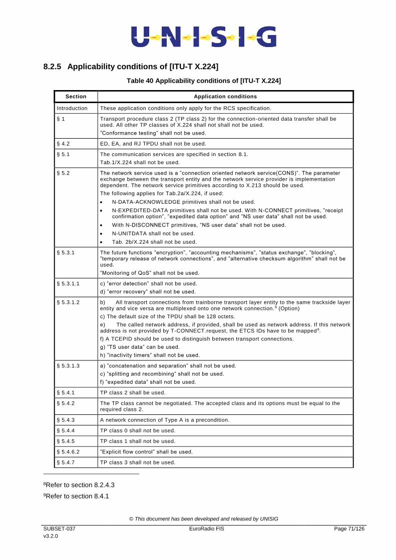
© This document has been developed and released by UNISIG
SUBSET-037
v3.2.0
EuroRadio FIS Page 71/126
8.2.5 Applicability conditions of [ITU-T X.224]
Table 40 Applicability conditions of [ITU-T X.224]
Section Application conditions
Introduction These application conditions only apply for the RCS specification.
§ 1 Transport procedure class 2 (TP class 2) for the connection-oriented data transfer shall be used. All other TP classes of X.224 shall not shall not be used.
”Conformance testing” shall not be used.
§ 4.2 ED, EA, and RJ TPDU shall not be used.
§ 5.1 The communication services are specified in section 8.1.
Tab.1/X.224 shall not be used.
§ 5.2 The network service used is a ”connection oriented network service(CONS)”. The parameter exchange between the transport entity and the network service provider is implementation dependent. The network service primitives according to X.213 should be used.
The following applies for Tab.2a/X.224, if used:
N-DATA-ACKNOWLEDGE primitives shall not be used.
N-EXPEDITED-DATA primitives shall not be used. With N-CONNECT primitives, ”receipt confirmation option”, ”expedited data option” and ”NS user data” shall not be used.
With N-DISCONNECT primitives, ”NS user data” shall not be used.
N-UNITDATA shall not be used.
Tab. 2b/X.224 shall not be used.
§ 5.3.1 The future functions ”encryption”, ”accounting mechanisms”, ”status exchange”, ”blocking”, ”temporary release of network connections”, and ”alternative checksum algorithm” shall not be used.
”Monitoring of QoS” shall not be used.
§ 5.3.1.1 c) ”error detection” shall not be used.
d) ”error recovery” shall not be used.
§ 5.3.1.2 b) All transport connections from trainborne transport layer entity to the same trackside layer entity and vice versa are multiplexed onto one network connection. 8 (Option)
c) The default size of the TPDU shall be 128 octets.
e) The called network address, if provided, shall be used as network address. If this network address is not provided by T-CONNECT.request, the ETCS IDs have to be mapped 9.
f) A TCEPID should be used to distinguish between transport connections.
g) ”TS user data” can be used.
h) ”inactivity timers” shall not be used.
§ 5.3.1.3 a) ”concatenation and separation” shall not be used.
c) ”splitting and recombining” shall not be used.
f) ”expedited data” shall not be used.
§ 5.4.1 TP class 2 shall be used.
§ 5.4.2 The TP class cannot be negotiated. The accepted class and its options must be equal to the required class 2.
§ 5.4.3 A network connection of Type A is a precondition.
§ 5.4.4 TP class 0 shall not be used.
§ 5.4.5 TP class 1 shall not be used.
§ 5.4.6.2 ”Explicit flow control” shall be used.
§ 5.4.7 TP class 3 shall not be used.
8Refer to section 8.2.4.3
9Refer to section 8.4.1

© This document has been developed and released by UNISIG
SUBSET-037
v3.2.0
EuroRadio FIS Page 72/126
Section Application conditions
§ 5.4.8 TP class 4 shall not be used.
§ 5.5 TP class 4 with ”connectionless-mode network service (CNLS)” shall not be used.
§ 6.1.1.3 All transport connections between the same pair of transport layer entities are multiplexed onto one network connection.10 (Option)
Procedures for ”re-synchronisation”, ”reassignment after failure” and ”splitting” shall not be used.
Note 3: The value of the appropriate delay should be 0s.11
Note 4: shall not be used.
Note 5: shall not be used.
§ 6.1.2 ”connectionless-mode network service” shall not be used.
§ 6.2.2 N-EXPEDITED-DATA and N-UNITDATA primitives shall not be used.
§ 6.2.3 ”connectionless-mode network service” shall not be used.
The network expedited variant shall not be used.
§ 6.4 ”concatenation and separation” shall not be used.
§ 6.5.2 N-UNITDATA primitives shall not be used.
§ 6.5.3 The following TPDU parameters shall not be used:
use of extended format;
version number;
protection;
checksum;
additional option selection;
alternate protocol classes;
acknowledge time;
inactivity time;
residual error rate;
reassignment time;
Option “non-use of explicit flow control in class 2”.
The following TPDU parameters should not be used:
TPDU size (proposed and selected);
preferred maximum TPDU size (proposed and selected).
If these parameters are used, the receiver shall ignore them.
10Refer to section 8.2.4.3
11Refer to section 8.2.4.4

© This document has been developed and released by UNISIG
SUBSET-037
v3.2.0
EuroRadio FIS Page 73/126
Section Application conditions
§ 6.5.4 Transport connections are only established by the initiator of the network connection.
Optionally, the responder can try to establish a transport connection. If it cannot be negotiated with peer transport layer entity or peer TS user, the transport connection establishment request will be rejected.
”splitting and recombining” shall not be used.
The timer TS1 is a matter of local implementation.
The network expedited variant shall not be used.
a) A TCEPID should be used as a reference.
c) ”initial credit” equals to 15 for transport connections with application type ATP; ”initial credit” equals to 1 for all other transport connections (if option ”Multiplexing” is used).
e) ”acknowledge time” shall not be used.
f) ”checksum” shall not be used.
g) ”protection” shall not be used.
h) ”inactivity time” shall not be used.
o) Option “non-use of explicit flow control in class 2” shall not be used .
The following parameters shall not be negotiated:
i) ”Protocol class” shall be always 2; ”alternative class” shall not be used.
Table 3/X.224 shall not be used. The following parameters shall not be negotiated:
j) The default size of the TPDU shall be 128 octets. This shall be maximum size usable.
k) ”Preferred maximum TPDU size” should not be used.
l) ”extended format” shall not be used.
m) ”checksum” shall not be used.
n) The parameter value of ”priority” shall be set according to the value of transport priority 12.
p) ”network receipt confirmation” and ”network expedited data transfer” shall not be used.
q) ”transport expedited data transfer” shall not be used.
r) ”use of selective acknowledgement” shall not be used.
s) ”use of request acknowledgement” shall not be used.
t) ”version number” shall not be used.
u) ”reassignment time parameter” shall not be used.
§ 6.5.5 ”connectionless-mode network service” shall not be used.
§ 6.6 The required class and options must be accepted.
§ 6.7.1 The explicit ”release procedure” shall be used.13
§ 6.7.1.4 The implicit ”release procedure” shall not be used. If the network connection is interrupted, an error indication should be given to the application.
§ 6.7.1.5 The orderly release of the transport connection requires the availability of the network connection.
The release may result in discarding of TPDUs.
Note 5: a network connection shall be immediately released in order when all transport connections multiplexed onto the network connection have been released.
Note 6: The timer TS2 is a matter of local implementation.
§6.7.2 ”connectionless-mode network service” shall not be used.
§ 6.8 ”Error release” shall be used.
On receipt of N-RESET.indication a N-DISCONNECT.request has to be issued.
§ 6.9.1.2 N-EXPEDITED-DATA primitives shall not be used.
§ 6.9.1.4.2 f) Add: The DST-REF parameter shall be mapped onto the local ”transport connection endpoint identifier (TCEPID)”.
§ 6.9.2 ”connectionless-mode network service” shall not be used.
12Refer to section 8.4.2.4.4
13Refer to 8.2.4.4

© This document has been developed and released by UNISIG
SUBSET-037
v3.2.0
EuroRadio FIS Page 74/126
Section Application conditions
§ 6.11 ”expedited data transfer” shall not be used.
§ 6.12 ”reassignment after failure” shall not be used.
§ 6.13 ”retention and acknowledgement of TPDUs” shall not be used.
§ 6.14 ”re-synchronisation” shall not be used.
§ 6.15 Details of multiplexing are specified in section 8.2.4.3.
§ 6.15.2 ED, EA, and RJ TPDUs shall not be used.
§ 6.15.3 Note 2: ”concatenation” shall not be used.
§ 6.16 Explicit flow control shall be used.
§ 6.17 ”checksum” shall not be used.
§ 6.18 ”frozen reference” shall not be used.
§ 6.19 ”re transmission on time-out” shall not be used.
§ 6.20 ”resequencing” shall not be used.
§ 6.21 ”inactivity control” shall not be used.
§ 6.22.2 ”connectionless-mode network service” shall not be used.
§ 6.23 ”splitting and combining” shall not be used.
§ 7 Tab.6/X.224 shall not be used. Refer to Table 38.
§ 8 TP class 0 shall not be used.
§ 9 TP class 1 shall not be used.
§ 10.2.1 d) ”concatenation and separation” shall not be used.
f) ”multiplexing and de-multiplexing” are used.
§ 10.2.3 Data transfer without flow control shall not be used.
§ 10.2.4.1 ”segmenting and reassembling” are used.
§ 10.2.4.3 ”Expedited data transfer” shall not be used.
§ 11 TP class 3 shall not be used.
§ 12 TP class 4 shall not be used.
§ 13.1 Table 8/X.224: ED, EA and RJ TPDUs shall not be used.
§ 13.3.3 b) ”initial credit” equals 15 for transport connections with application type ATP ”initial credit” equals to 1 for all other transport connections (if option ”Multiplexing” is used).
e) TP class 2;
Options:
”use of normal format in all classes”
”use of explicit flow control in class 2”.
§ 13.3.4 The following parameters shall be used in the variable part:
a) TSAP-IDs are used. The parameter length shall be equal to 5. The parameter value contains the respective transport selector14.
l) ”Priority” shall be used. The parameter value shall be set according to the value of transport priority 15.
§ 13.5.4 The variable part of the DR TPDU should not be used.
§ 13.7.1 ”extended format” shall not be used.
§ 13.7.4 The variable part shall not be used.
14Refer to section 8.2.4.6
15Refer to section 8.4.2.4.4

© This document has been developed and released by UNISIG
SUBSET-037
v3.2.0
EuroRadio FIS Page 75/126
Section Application conditions
§ 13.8 ED TPDUs shall not be used.
§ 13.9.1 ”extended format” shall not be used.
§ 13.9.4 The variable part shall not be used.
§ 13.10 EA TPDUs shall not be used.
§ 13.11 RJ TPDUs shall not be used.
§ 14 ”Conformance” with ITU-T Rec. X.224 shall not be required.
Annex A TP class 0, 1, 3 and 4 and ”connectionless mode network service” shall not be used .
Annex B The ”network connection management sub protocol(NCMS)” shall not be used.
Annex C ”Conformance” with ITU-T Rec. X.224 shall not be required.
Annex D ”checksum” shall not be used.
Annex E shall not be used.
8.2.6 Time sequences
8.2.6.1 The time sequences are shown in the appropriate OSI layer service definition standards
(e.g. for layer 4 refer to [ITU-T X.214]). This chapter illustrates the interaction of the
layers.
8.2.6.2 Figure 16 contains the connection establishment by trainborne RCS only. The signalling
connection between RCS and the Mobile Termination is established after “power-on” of
the Mobile Termination to provide the radio resources and mobility management.

© This document has been developed and released by UNISIG
SUBSET-037
v3.2.0
EuroRadio FIS Page 76/126
Layer 4 Layer 3 Layer 2
SABME
Bm channel
GSM 07.07 Signaling
DL- CONN.req
UA DL- CONN_conf
(1.segment) DL- DATA.req
DL- DATA.req ( n.segment)
... ...
N- CONN.req
N- CONN.conf
N- DATA.req (CR TPDU)
I( 1.segment)
I( n.segment)
T- CONN.req
(user data)
CR TPDU
+CBST=<m> D<number>
CONNECT
Figure 16 Detailed protocol sequence during connection establishment (requesting side only)
8.2.6.3 Note: The lower part of Figure 16 shows the segmentation of the CR TPDU as an
example of a TPDU size > 123 octets.

© This document has been developed and released by UNISIG
SUBSET-037
v3.2.0
EuroRadio FIS Page 77/126
Layer 3 Layer 2
I( 1.segment)(1.segment)
DL-DATA.req
DL-DATA.req
(n.segment) I( n.segment)
...
...
N-DATA.req
(DT TPDU)
T-DATA.req DT TPDU
Layer 4
Figure 17 Detailed protocol sequence during data transfer (requesting side only)
Layer 3 Layer 2
I( 1.segment)(1.segment)
DL-DATA.req
DL-DATA.req
(n.segment) I( n.segment)
...
...
N-DATA.req
(DR TPDU)
T-DISC.req DR TPDU
Layer 4
Figure 18 Detailed protocol sequence during connection release (requesting side only)
8.2.7 Relationships of PDUs and SDUs
8.2.7.1 This chapter contains examples of layer overheads based on a 25 octet data field in
HDLC frames.
8.2.7.2 The safety layer, if applied, adds a header and the MAC to the user data.
8.2.7.3 Transport connections are multiplexed on one network connection according to their
transport priority. The layer 4 adds a header to the user data.
8.2.7.4 If the TS user provides a normal priority TSDU of appropriate length (<=123 octets), the
layer 4 does not segment/reassemble the user data (Figure 19). Segmenting and
reassembling in layer 3 results in a 2 byte segment header.
8.2.7.5 In the case of a non-safe connection Figure 19 is still valid, but without the second line
(SaPDU).

© This document has been developed and released by UNISIG
SUBSET-037
v3.2.0
EuroRadio FIS Page 78/126
flag FCS control data
2 <=34 2 1
header application info
MAC
8 User data <=114 octets
header
5
header
2 32
first segment
flag address
1 1 HDLC frame
NPDU
TPDU
SaPDU
Application PDU
Length in octets
The trailer flag is required, if the next frame does not immediately follow.
header 1
header
2 <= 32
last segment
...
Figure 19 Example of segmenting/reassembling in layer 3
8.2.7.6 If the TS user did not provide a normal priority TSDU of appropriate length, the layer 4
segments/reassembles the user data into/from TPDUs of standard length of 128 octets.
Segmenting and reassembling in layer 4 will result in a 5 byte header added to each
segment (Figure 20). The layer 3 header is additionally required to be consistent with the
NPDU format of the other connections.

© This document has been developed and released by UNISIG
SUBSET-037
v3.2.0
EuroRadio FIS Page 79/126
HDLC frame
TSDU
SaPDU
Application PDU header application info
MAC
8
<=23
header
5 <=123
last segment
header 1
header
5
header
2 32
first segment NPDU
TPDU
header
2 <= 32
last segment
...
first segment
123 octets
user data > 114 octets
flag FCS control data
2 <=34
1
flag address
1 1 2
Figure 20 Example of segmenting/reassembling in layer 4 and layer 3
Figure 21 Example of layer overhead of high priority data
High priority PDU
HDLC frameflagFCScontrol data
1 <=25 1
flag address
1 1 2
application info
<=25

© This document has been developed and released by UNISIG
SUBSET-037
v3.2.0
EuroRadio FIS Page 80/126
8.3 Communication protocols for PS
8.3.1 Introduction
8.3.1.1 This section provides a precise specification of the communication protocols of the user
channel over PS. The protocol specifications are described layer by layer. Table 41 shows
the delta to existing standards.
8.3.1.2 An APN shall be provided that is dedicated to ETCS traffic.
8.3.1.3 One dedicated PDP context ID for ETCS purposes shall be subscribed to each MT.
8.3.1.4 Only mobile initiated PDP context activations shall be supported for ETCS.
8.3.1.5 A PDP context shall be deactivated only by the OBU.
8.3.2 Adaptation Layer Entity (ALE)
8.3.2.1 Functions
8.3.2.1.1 The main functions of ALE are:
a) Adaptation between EuroRadio Safety Layer and TCP layer.
b) Establishment and Release of the TCP connection.
c) Conversion between Safety Layer packets to/from TCP stream.
d) Monitoring of channel availability.
8.3.2.1.2 All the above ALE functions are based on [Subset-098] (RBC-RBC Safe Communication
Interface), using the requirements specified in Table 41. The paragraphs below explain
the adaptation of Subset-098 for on-board to trackside safe communication.
Table 41. Applicability conditions of Subset-098
Section Application conditions
§ 1 Modification History INTRODUCTION
Not relevant.
§ 2 Table of Contents INTRODUCTION
Not relevant.
§ 3 introduction INTRODUCTION Not relevant.
§ 4 Reference architecture
Not relevant, except the following sentence in § 4.5.1.1.1: ‘High priority’ messages [Subset-037] are not required;
High priority messages are not supported in packet switched mode.
§ 5 Safe Functional Module
Not relevant.
§ 6 Communication Functional Module
All applicable except for the following rows of this table.
§ 6.1 General Not relevant, however not only RBC-RBC Safe Communication Interface, but generic on-board and trackside equipment.
§ 6.2.1.1.1 Systems are assumed both fixed and mobile.

© This document has been developed and released by UNISIG
SUBSET-037
v3.2.0
EuroRadio FIS Page 81/126
Section Application conditions
§ 6.2.1.1.2 Physical redundancy not supported on OBU side.
§ 6.3.1.1.1 Running not only on ground based systems.
§ 6.3.1.1.4 The diagram in figure 28 shows an example for a fixed connection, not over GSM -R (GPRS).
§ 6.3.2.1.3 Only Class D.
§ 6.3.2.1.4 One single physical link only, with only one TCP connection, no redundancy used.
§ 6.3.3 Class A request
Not relevant.
§ 6.3.4.1.1 A request for a Class D quality of service shall result in the Adaptation Layer attempting to make only one TCP connections to the remote Adaptation Layer entity. This connection shall be used to transfer all data and control messages. The safe connection shall operate only on this link. The exact details of how this link shall be monitored and managed are contained in §6.6.
§ 6.4.1.1.3 Managing of the redundancy is not applicable.
§ 6.5.2.1.1 Transport priority is not used.
§ 6.5.2.2.1 Specified in chapter 8.3.2.3.
§ 6.5.2.5.4 TCP_LISTEN_ON_PORT specified in 8.3.2.4.1
§ 6.5.2.6.1 Every connection between two subsystems is realised through only one transport connection.
§ 6.6.1 Class A (optional for implementation)
Not relevant.
§ 6.6.2 Class D is used.
One single physical link only, with only one TCP connection, no redundancy used.
§ 6.8 Specified in chapter 8.3.3
§ 6.8.3.1.2 IP v4 is mandatory,
§ 6.9.3.1.1 Specified in chapter 8.3.2.3.
§ 7 INFORMATIVE ANNEX
Not relevant.
8.3.2.2 Redundancy of the ALE Server physical interfaces
8.3.2.2.1 The communication between OBU and RBC is realised by ALE client (on-board) / server
(trackside).
8.3.2.2.2 The ALE Server (trackside) may have several physical interfaces, but only one IP
address is responded to an ALE Client (on-board) by a DNS response, subsequent to a
DNS query of the ALE Client during connection establishment. The process how the ALE
Client manages the IP address of the server is a matter of implementation.
8.3.2.3 Addressing
8.3.2.3.1 Dynamic IP address allocation shall be used for the ALE client (on-board) and the IP
address is obtained during the PDP context activation (see Figure 22).
8.3.2.3.2 Instead, the ALE server (trackside) IP address shall be permanent.
8.3.2.3.3 If the optional parameter Network Address does not contain an IP address in the T-
CONNECT.request primitive a DNS query shall be used to resolve IP address.
8.3.2.3.4 To translate the ETCS id of the ALE server a DNS lookup shall be used.

© This document has been developed and released by UNISIG
SUBSET-037
v3.2.0
EuroRadio FIS Page 82/126
8.3.2.3.5 The format of the string (host name) sent to the DNS shall be:
“id<ETCS ID>.ty<ETCS-ID Type>.etcs”, using lowercase hexadecimal ASCII character
representation of the <ETCS ID> and <ETCS-ID Type>. Example: If the ETCS id type is
RBC and the ETCS ID is ‘1001 0011 1100 0000 1111 0101, the formatted string will be
‘id93c0f5.ty01.etcs’. See also Table 26.
8.3.2.3.6 The DNS feature shall comply with [RFC 1034 ] and [RFC 1035].
8.3.2.4 Listening port
8.3.2.4.1 The listening TCP port is 791116.
8.3.2.5 Connection Monitoring
8.3.2.5.1 Standard TCP Keep Alive shall be used, together with other TCP parameters and
features, see Table 42. Applicability conditions of TCP.
8.3.2.6 Co-ordinating functions
8.3.2.6.1 The co-ordinating function manages the AT-command interface and the switching
between the control plane (command state) and the user plane (data state).
8.3.2.6.2 The following tasks are performed by the co-ordinating function:
a) Registration with requested and appropriate GSM (same for CS and PS)
b) Connection refusal in case of an error
c) Error reporting and retrieving information on error reasons
d) Check GPRS attach status and attach if not already attached
e) Check PDP context activation and activate PDP context if not already active
f) Change the interface state to MT into on-line data state before connection
establishment.
g) Change the interface state to MT into AT command state after release of all
transport connections associated with the specific MT.
h) Establish the PPP and extract the ETCS DNS IP address.
i) Association of a MT with a requested transport connection.
8.3.2.6.3 In case a new PS mode connection is requested within the same network of an already
established one (e.g. RBC handover within the same network), the same MT as for the
already established connection shall be used.
8.3.3 TCP Layer
8.3.3.1 The transport layer protocol is TCP [RFC 793].
8.3.3.2 In the following Table 42, Mandatory (M) and Optional (O) TCP Features are specified
from ETCS operation point of view.
16 The range of port numbers from 1024 to 49151 are the registered ports. They are assigned by IANA for
specific service upon application by a requesting entity. On most systems, registered ports can be used by
ordinary users.

© This document has been developed and released by UNISIG
SUBSET-037
v3.2.0
EuroRadio FIS Page 83/126
8.3.3.3 The values of some TCP Parameters can be proposed in the DNS TXT field, see
8.4.1.13, but the applicability of such proposed values is optional, depending on the
implementation.
8.3.3.4 The configurable or not per connection is done from the Linux TCP implementation point
of view. Other implementations could have other restrictions.
Table 42. Applicability conditions of TCP
Feature RFC M/O Value Comments
1 Initial RTO 793
1122
M >=
TCP_RTO_MI
N
<
TCP_RTO_MA
X
(Recommende
d: =
TCP_RTO_MI
N)
Also known as “TCP_timeout_init”
Note: not configurable per connection
2 Minimum Retransmission Time 793
1122
M 1-5s
(Recommende
d: 4 s)
TCP_RTO_MIN: The RTO is not
allowed to be lower than this value
Note: not configurable per connection
3 Maximum Retransmission Timeout 793
1122
M >=5s
(Recommended: 10 s)
TCP_RTO_MAX: Should be set to a
value that defines the maximum
allowed time before a forced re-
transmission
Note: not configurable per connection
4 Karn and Jacobson's algorithm, with exponential back-off
1122 M Used Standard TCP feature to compute RTO
Note: not configurable per connection
6 TcpMaxConnectRetransmissions
793
1122
M 3 Number of SYN-packet retries; also known as “TCP_SYN_retries”
Note: not configurable per connection
7 TcpMaxDataRetransmissions 793
1122.
M 1-5
(Recommended: 3)
Also known as “TCP_retries2”
Note: not configurable per connection
8 TcpKeepAliveTime 793
1122
M 10-20 s
(Recommended: 12 s)
The interval to wait before probing the idle connection
Note: configurable per connection
9 TcpKeepAliveInterval 793
1122
M 2-5 s
(Recommende
d: 3 s)
The interval to wait before retrying the probe after an initial failure to respond:
Note: configurable per connection
10 TcpKeepAliveProbes 793
1122
M 2-4
(Recommende
d: 3)
The maximum number of times to retry the probe
Note: configurable per connection

© This document has been developed and released by UNISIG
SUBSET-037
v3.2.0
EuroRadio FIS Page 84/126
11 TcpUserTimeout 5482 O >=10
(Recommended: 20 s)
The TCP user timeout controls how
long transmitted data may remain
unacknowledged before a
connection is forcefully closed.
It is checked during RTO update.
Note: configurable per connection
12 TcpSack 2018
2883
M enabled Selective Acknowledgement
Note: not configurable per connection
13 TcpTimestamps 1323 M disabled Note: not configurable per connection
14 TcpNoDelay 896 M enabled Disables Nagel’s algorithm which concatenates small messages before sending them
Note: configurable per connection
15 TCP Push Bit 793 M enabled Force the processing of the receiver buffer
Note: not configurable per connection
16 Max TCP segment size 793 M <= 1416
(Recommended: = 1416)
Maximum value is MTU - sizeof(max TCP Header) - sizeof(max IP Header)
Where guaranteed MTU=1500 byte, sizeof(max TCP Header)=60 byte, sizeof(max IP Header) = 24 byte
Note: configurable per connection
8.3.4 Network Layer
8.3.4.1 The network layer protocol is IPv4 [RFC 791].
8.3.5 Data Link Layer
8.3.5.1 These interfaces, like PPP or Ethernet, are specified in the [EuroRadio FFFIS]
8.3.6 Time sequences
8.3.6.1 The time sequences are shown for the sublayers of the protocol stack which are applied
on top of GPRS.
8.3.6.2 Figure 22 contains the signalling flow for PS service setup (see also ANNEX H),
applicable at OBU side only. This signalling flow is necessary in the following cases:
after initialization of the Mobile Termination to provide the radio resources and
mobility management.
on explicit request from the application (i.e. border crossing).
following loss of radio coverage.
8.3.6.3 Network registration shall be performed followed by:
on all mobiles: a single attempt of GPRS attachment (+CGATT) with timeout of 5s;
on one mobile: a single attempt of PDP context activation (+CGACT) with timeout
of 3s.

© This document has been developed and released by UNISIG
SUBSET-037
v3.2.0
EuroRadio FIS Page 85/126
8.3.6.4 The successful network registration shall be reported to the application, even in case of
GPRS attachment (+CGATT) and/or PDP context activation failure, which shall then be
continuously monitored on one mobile by a polling task in the following conditions:
Start the polling on all MT’s, successfully registered on a network, not associated to
transport connections and in command state, otherwise don’t poll.
Every predefined polling period (max 10s), perform GPRS attachment (+CGATT)
and PDP context activation (+CGACT).
As soon as successful/unsuccessful PS status is received form the MT, the PS
status is changed accordingly.
When the polling period expires, if there is no PS status received from the MT, the
PS status is not updated and the ongoing GPRS attachment (+CGATT) and PDP
context activation (+CGACT) shall be aborted and restarted.
If the association of the MT with a transport connection is requested by an
application while polling is ongoing, the polling shall be aborted anytime, and the
status of PS shall be the last known one (successful or unsuccessful).
The polling procedure is managed independently on all MTs.
8.3.6.5 Figure 23 contains the connection establishment (OBU side only) protocol sequence.
8.3.6.6 Figure 24 contains the detailed protocol sequence during data transfer.
8.3.6.7 Figure 25 contains the detailed protocol sequence for connection release.
8.3.6.8 Note: the exchange of AU3 and AR SaPDUs are out of scope for transport connection
establishment.
8.3.6.9 Note: the AT commands shown in the pictures are specified in the [EuroRadio FFFIS].

© This document has been developed and released by UNISIG
SUBSET-037
v3.2.0
EuroRadio FIS Page 86/126
Figure 22 Time sequence “Network registration and PS service setup” (OBU side only)
OBU MT
OBU-AP OBU-ER
CFM
SFM
MNID
Sa-REGISTR.req
+CGREG
Network Registration
+COPS
+CGREG:2,1
OK
+CGATT
MNID
Sa-REGISTR.ind
Registered to status
GPRS attach
PDP context activation
(see ANNEX H)
Registration request
OK
OK
+CGACT
Set initial conditions
(reporting etc)
OK
GPRS activation request
+CGDCONT
OK
+CGEQREQ
OK
timeo
ut
timeo
ut

© This document has been developed and released by UNISIG
SUBSET-037
v3.2.0
EuroRadio FIS Page 87/126
Figure 23 Time sequence “Connection establishment” (OBU side only)
ALE
sublayer
T-CONN.req
AU1 SaPDU
TCP segment (AU1 ALEPKT (AU1
SaPDU))
TCP_
Open_Port
3 way handshaking
DNS query for RBC IP address
AU1
ALEPKT
TCP Coord.
function
Layer 4 Layer 3
Check PS status.
If not OK, see ANNEX H
Establish PPP stack
TS 27.007 Signalling
+CGDATA
RBC IP address
TCP_
Connected
TCP_
Send_Data
DNS
server
OBU IP address DNS IP address
TCP segment (AU2 ALEPKT (AU2
SaPDU))
TCP_
DataReady
TCP_
ReadData
AU2
ALEPKT
T-
CONN.conf
AU2
SaPDU
OBU IP address
Enter data state
DNS IP address
Allocation
function

© This document has been developed and released by UNISIG
SUBSET-037
v3.2.0
EuroRadio FIS Page 88/126
Figure 24 Time sequence “Data Transfer”
ALE
sublayer
T-DATA.req
DT SaPDU
TCP_ Send_Data
TCP
segment
DT SaPDU
TCP_
Data_Ready DT
ALEPKT
TCP_ Read_Data
(DT ALEPKT)
DT
ALEPKT
T-DATA.ind
DT SaPDU
TCP ALE
sublayer TCP
Layer 4 Layer 4
Allocation
function

© This document has been developed and released by UNISIG
SUBSET-037
v3.2.0
EuroRadio FIS Page 89/126
Figure 25 Time sequence “Connection Release”
8.3.7 Relationship of PDUs
8.3.7.1 This section contains examples of layer overheads of the protocol stack based on top of
GPRS.
8.3.7.2 The safety layer adds a header and the MAC to the user data.
8.3.7.3 The ALE sublayer adds a 10 octet header to the user data.
8.3.7.4 The transport layer adds a 24 octet header (or more) to the user data.
8.3.7.5 The IP layer adds a 20 or 24 octet header to the user data.
8.3.7.6 Neither the ALE sublayer nor the transport layer segment/reassemble the user data.
ALE
sublayer
T-DISC.req
DI SaPDU TCP_ Send_Data
TCP
segment
DI SaPDU
TCP_ Data_Ready
DI ALEPKT
TCP_ Read_Data
(DI ALEPKT)
DI ALEPKT
T-DISC.ind
DI SaPDU
TCP ALE
sublayer TCP
Layer 4 Layer 4
TCP_Close
Normal TCP
closing
TCP_Close
Allocation
function

© This document has been developed and released by UNISIG
SUBSET-037
v3.2.0
EuroRadio FIS Page 90/126
Figure 26 Relation between PDUs
8.4 Management of Communication Functional Module
8.4.1 Call and ID-Management
8.4.1.1 The CFM has to establish the connections on demand between peer applications (i.e.
CFM users). The details of the following tasks are a matter of implementation.
8.4.1.2 The RCS communication functional module optionally offers several logical connections
between the trackside and the on-board equipment via the same physical channel. This
option is not required for ETCS level 1 radio in-fill unit. See 8.1.1.6.
8.4.1.3 The ”transport address” is a generic name that is used to identify a set of transport service
access points (TSAPs) which are all located at the interface between a higher layer and
the transport layer of the CFM. If a generic name is used to denote an object, then exactly
one member of the set of objects will be selected.
8.4.1.4 The transport address is used to access a single transport service (TS) user entity. The
network address by itself is not sufficient to identify a particular CFM user entity. It is
necessary to refer to the requested CFM user entity type by using a special identifier or
address qualifier: the application type.
Application data
User data
<= 1023
MAC
8
Header
1
Header
10
Header
>=20
Header
20 or 24
SaPDU
Application PDU
ALEPKT
TCP segment
IP
packet
Length in octets

© This document has been developed and released by UNISIG
SUBSET-037
v3.2.0
EuroRadio FIS Page 91/126
NSAP NSAP NSAP NSAP
ATP application (calling CFM user )
Safety layer entity
Transport entity
Transport layer TSAP
Address mapping
Network layer
ATP application (called CFM user)
Safety layer entity
Transport entity
Transport layer TSAP
Network layer
TSAP TSAP
SaSAP SaSAP
Other CFM user
Safety layer Safety layer
External address info
CdA = ETCS ID type, ETCS ID appl.type=ATP
CdA = E.164-No.
Network
Applic. type = ATP Applic. type = ...
CR TPDU
CdA = (application type, ETCS ID type, ETCS ID)
appl.type=ATP
Address adaptation
07.07 dial string
MT2
CdA = E.164-No.
CdA = ETCS ID type, ETCS ID
Figure 27 Example of address mapping
8.4.1.5 Transport layer entities and CFM user entities are bound together at TSAPs. Every CFM
user entity may be bound to one or more TSAPs. This is a matter of implementation.
There is no relationship between TSAPs and multiplexing. The multiplexed transport
connections may terminate at different TSAPs.
8.4.1.6 The addresses are used in the T-CONNECT primitives (transport address) and N-
CONNECT-primitives (network address) at the service interface. If a CFM user entity (e.g.
the safety layer entity) wants to establish a connection with another CFM user entity, it
provides information to address the called CFM user (e.g. an ETCS ID type and ETCS ID)
and the application type. This address information has to be mapped into the format and
structure requested by the CFM for connection establishment.
8.4.1.7 Figure 27 gives an example of address information mappings during the connection
establishment from trainborne CFM to trackside CFM. The calling TS user entity (i.e. in
this example the safety layer entity) obtains the called transport address from the
application (ETCS ID type and ETCS ID). The address information will be passed through
the SFM towards the CFM.
8.4.1.8 The calling CFM has the following tasks:
To check, that a Mobile Termination is registered with the mobile network contained
in the T-CONNECT.request;

© This document has been developed and released by UNISIG
SUBSET-037
v3.2.0
EuroRadio FIS Page 92/126
In PS mode, to check that the MT is attached to the mobile network contained in
the T-CONNECT.request and to attach the MT if necessary;
In PS mode, to activate the PDP context activation if not yet active;
To associate the requested connection with an appropriate Mobile Termination;
To derive the called network address from address information indicating the called
CFM user;
To insert into the connection request (CR) TPDU the called transport selector (in
the case of train initiated physical connection establishment according to Figure 15)
and the calling transport selector;
To select the local NSAP by which the network service primitives (if applicable) is
issued.
If the PS service setup is successful (see ANNEX H), to perform an ETCS DNS
query using the ETCS ID type and ETCS ID contained in the received T-
CONNECT.request.
To store the Transmission mode (PS or CS) received in the ETCS DNS answer, to
be used to establish the connection requested in the T-CONNECT.request.
The table associating the transmission mode (PS or CS) with the ETCS ID type and
ETCS IDs shall not be pre-configured, and shall be stored to be used also after
reboots.
8.4.1.9 The following rules are applied to derive the called network address in the case of train
initiated connection establishment (see also ANNEX I):
1. If the T-CONNECT.request primitive received contains an unknown ETCS ID type
and ETCS ID, the address contained in the T-CONNECT.request primitive shall be
used for physical connection establishment. The network address is transparent for
CFM. If the network address is not contained in the T-CONNECT.request primitive,
the call shall be established towards the most appropriate RBC by means of the
short dialling code, refer to [EIRENE SRS]). All the following points shall be
ignored.
2. The ETCS on-board equipment shall check the information stored in the
Transmission Mode table associated to the ETCS ID type and ETCS ID contained
in the received T-CONNECT.request primitive.
3. If there is no Transmission Mode information associated and the PS service setup
is not successful, the following actions shall be executed:
a. the Transmission Mode information shall be set to CS;
b. the address contained in the T-CONNECT.request primitive shall be used
for physical connection establishment. The network address is transparent
for CFM;
c. if the network address is not contained in the T-CONNECT.request
primitive, the call shall be established towards the most appropriate RBC by
means of the short dialling code, refer to [EIRENE SRS]).

© This document has been developed and released by UNISIG
SUBSET-037
v3.2.0
EuroRadio FIS Page 93/126
4. If there is no Transmission Mode information associated and the PS service setup
is successful, a DNS query using the ETCS ID type and ETCS ID contained in the
received T-CONNECT.request primitive shall be sent:
a. If the answer from the DNS contains no IP address and a TXT field
indication CS Mode (see below), the Transmission Mode information shall
be set to CS and the address contained in the T-CONNECT.request
primitive has to be used for physical connection establishment. The network
address is transparent for CFM; if the network address is not contained in
the T-CONNECT.request primitive, the call has to be established towards
the most appropriate RBC by means of the short dialling code, refer to
[EIRENE SRS]);
b. If the answer from the DNS contains an IP address, the Transmission Mode
information shall be set to PS and the IP address shall be used for the
connection establishment; the IP address shall not be stored for subsequent
connection establishment requests to the same RBC.
c. In the following error cases the behaviour shall be the same as for a:
i. if no answer is received from the DNS after dns_lookup_timeout, see
8.4.2.3.2.1;
ii. or if is received an answer from the DNS with an error message;
iii. or if the answer from the DNS contains no IP address but no TXT
file;
iv. or if the answer from the DNS contains a wrongly formatted TXT
field,
5. If the Transmission Mode information associated is CS, the following actions shall
be executed:
a. the address contained in the T-CONNECT.request primitive has to be used
for physical connection establishment. The network address is transparent
for CFM;
b. if the network address is not contained in the T-CONNECT.request
primitive, the call has to be established towards the most appropriate RBC
by means of the short dialling code, refer to [EIRENE SRS]).
c. Update of the Transmission Mode information simultaneously to the CS
connection:
i. Check for association of MT to transport connections. If all MT are
associated, the update will be delayed until one is not associated. If
the established CS connection is released before an MT is available
the update shall be aborted.
ii. If the PS service setup is successful on the MT, an ETCS DNS
query using the ETCS ID type and ETCS ID contained in the
received T-CONNECT.request primitive shall be executed.
iii. If the answer from the DNS contains an IP address, the
Transmission Mode information associated to the ETCS ID type and

© This document has been developed and released by UNISIG
SUBSET-037
v3.2.0
EuroRadio FIS Page 94/126
ETCS ID contained in the received T-CONNECT.request primitive
shall be changed to PS, but the IP address itself shall not be stored.
iv. In all the other cases nothing shall be done.
6. If the Transmission Mode information associated is PS and if the PS service setup
is not successful, a T-DISCONNECT.indication primitive with reason 3 and sub-
reason 2, according to Table 49, shall be sent to the CFM user.
7. If the Transmission Mode information associated is PS and if the PS service setup
is successful, an ETCS DNS query using the ETCS ID type and ETCS ID contained
in the received T-CONNECT.request primitive shall be sent:
a. If the answer from the ETCS DNS contains no IP address but a TXT field
indication CS Mode (see below), the Transmission Mode information shall
be set to CS and a T-DISCONNECT.indication primitive with appropriate
reason shall be sent to the CFM user;
b. If the answer from the DNS contains an IP address, the IP address shall be
used for the physical connection establishment, while the TXT field shall be
used for suggested specific transmission protocol parameters (see
8.4.1.13); the IP address shall not be stored, before any other TCP
connection or reconnection, a DNS query shall be made;
c. In the following error cases, a T-DISCONNECT.indication primitive with
appropriate reason shall be sent to the CFM user:
i. if no answer is received from the DNS after dns_lookup_timeout, see
8.4.2.3.2.1;
ii. or if is received an answer from the DNS with an error message;
iii. or if the answer from the DNS contains no IP address but no TXT
file;
iv. or if the answer from the DNS contains a wrongly formatted TXT
field;
v. or in case of a not successful connection establishment.
8.4.1.10 The DNS Record TXT field in scope of EuroRadio is a semicolon separated and ended list
of uniquely named, by equal sign, comma separated lists containing unique strings
including empty strings. Characters are ASCII. E.g. "txm=cs;foo=bla;tp=blub,,b;".
8.4.1.11 Transmission mode PS will be indicated by an IP address in the A field of the DNS record.
8.4.1.12 If no PS mode will be supported by the RBC other supported RBC EuroRadio
transmission modes are indicated by the “txm” named list of the DNS record’s TXT field.
Indicate able transmission modes are:
CS by the string “cs” contained in the txm list
Future releases might support additional transmission modes.
8.4.1.13 Suggested specific transmission protocol parameters are indicated by the “tp” named list
of the DNS record’s TXT field. Each entry of this list matches, in order, to a transport
parameter as per Table 42 which is commented as “configurable per connection”. I.e. for
“tp=<p1>,<p2>,<p3>,<p4>,<p5>;” the following correspondence holds:

© This document has been developed and released by UNISIG
SUBSET-037
v3.2.0
EuroRadio FIS Page 95/126
<p1> : TcpKeepAliveTime
<p2> : TcpKeepAliveInterval
<p3> : TcpKeepAliveProbes
<p4> : TcpUserTimeout
<p5> : Max TCP segment size.
Omitting the setting of a parameter is indicated by an empty string at the corresponding
list position. The strings are to be interpreted as of the intended value’s unit (e.g. the
<p1> parameter represents seconds, the <p3> parameter represents “count”).
Numbers are decimals represented as strings, i.e. “580” for the decimal number 580.
In the following cases, the suggested parameters shall not apply at all:
In case of definition range mismatch between any single parameter with its general
value range as per Table 42 “Value” column
In case of expected parameter count mismatch
The use of a suggested parameter is mandatory unless it is not settable in the used
TCP implementation.
8.4.1.14 Note: The details of local call and ID management (e.g. address mapping) are out of
scope for this FIS.
8.4.1.15 Table 43 shows the defined combinations of address information values.
Table 43 Address information (train initiated call set-up)
ETCS ID type
ETCS ID Network address Action Remarks
RBC RBC ID RBC network address provided
CS mode: use network address, update the Transmission Mode via the other MT if possible
PS mode: retrieve IP address from DNS
RBC RBC ID Network address not provided or
Default value ”NA unknown”
CS mode: use short dialling code “Most appropriate RBC”, update the Transmission Mode via the other MT if possible
PS mode: retrieve IP address from DNS
Short dialling code 15xx [EIRENE SRS]
“unknown” Default value ”ETCS ID unknown”
Network address not provided or
Default value ”NA unknown”
CS mode: use short dialling code ”Most appropriate RBC”, NO update of the Transmission Mode via the other MT
PS mode: cannot be used
Default for addressing in CS
“unknown” Default value ”ETCS ID unknown”
RBC network address provided
CS/PS mode: use network address PS mode: not used for ETCS applications
8.4.1.16 The ConnectRequest TPDU (CR TPDU) and the ConnectConfirm TPDU (CC TPDU)
contain the calling and the called transport selectors in the format specified for the TPDUs
(see section 8.2.4.6).

© This document has been developed and released by UNISIG
SUBSET-037
v3.2.0
EuroRadio FIS Page 96/126
8.4.1.17 In CS mode the trackside called network address will be a generic address to identify a
set of network service access points (NSAPs), which are bound to the ”Primary rate
access” (ISDN-like networks). The called network number should be a ”hunting number”:
incoming calls to the network number will be distributed by the terminating exchange (or
the PABX) among a group of interfaces. One of the idle interfaces will be selected to
receive the call.
8.4.1.18 In PS mode the trackside called network address will be an IP address identifying the
peer RBC.
8.4.1.19 The trackside sets of TSAPs are bound to special CFM user entities (e.g. in Figure 27 the
safety layer entity is bound to a special TSAP). The CFM user entity A is bound to a TSAP
but actually not used (may be it is a non-safe application layer entity, which has to use
another TSAP and application type).
8.4.1.20 The transport layer entity in the called CFM uses:
the address information contained in the connection request (CR) TPDU to derive
the called ETCS ID type and ETCS ID and to select one appropriate TSAP (based
on the application type received);
the responding ETCS ID type and ETCS ID contained in the T-
CONNECT.response primitive to build the connection confirm (CC) TPDU.
8.4.1.21 If the transport layer entity of the called side is not able to select a TSAP bound with the
requested application type, the CR TPDU will be rejected.
8.4.2 Configuration management
8.4.2.1 The local O&M stack provides an initial set of configuration parameters. This set can be a
default set installed during manufacturing. If more than one default set exists, one of these
sets can be selected prior to the journey by a local management action based on national
railway rules. All these off-line management actions are out of scope of this FIS.
8.4.2.2 Configuration parameters for CS mode
Table 44 Layer 2 configuration parameters for CS mode17
Parameter Symbol Defined range of values
Recommended values Comments
Address A, B Calling entity: A
Called entity: B
Window size k 1 - 127 1 - 61
The window size can be different in both directions.
(see ANNEX F)
Acknowledge time T1 > 500 ms 0,8 - 2 s
Local processing delay time T2 < 80 ms Implementation dependent
17 All recommended values in this table should be optimised (e.g. on track characteristics, industrial / rural
locations etc.)

© This document has been developed and released by UNISIG
SUBSET-037
v3.2.0
EuroRadio FIS Page 97/126
Parameter Symbol Defined range of values
Recommended values Comments
Out of service time T3 T3 >> T4 Matter of implementation (to be used only if T4 is supported)
Inactivity time T4 Recommended value T4 >N2 * T1
T4 >> T1
Matter of implementation
maximum number of bits in an I frame
N1 > 0 240<N1<1024.
Flags are not included.
Receive buffers shall support N1 =1024.
Recommended value for transmission = 312 (This is equal to 4 frames per 1 TPDU
Maximum number of retransmission attempts
N2 > 0 3 – 6. Note: ISO/IEC 7776 specifies the number of transmissions = N2+1
Recommended value: 5
Error detection and correction
FCS-16 No options
8.4.2.2.1 The description of the layer 2 configuration parameters for CS mode is provided by
[ISO/IEC 7776] section 5.7.
8.4.2.2.2 Timer T5 shall not be used.
8.4.2.2.3 The description of the layer 3 configuration parameters for CS mode is provided in [ITU-
T T.70].
Table 45 Layer 3 configuration parameters for CS mode
Parameter Symbol Range of values
Applied value Comments
Maximum number of octets in a segment
NL3seg NL3seg=(N1/8)-5 The layer 3 header is included.
NL3seg is related to the layer 2 frame length N1
8.4.2.2.4 The description of the layer 4 configuration parameters for CS mode is provided by [ITU-
T X.224].
Table 46 Layer 4 configuration parameters for CS mode
Parameter Symbol Range of values Applied value Comments
TP class TP x TP 2 No choice
Procedure elements Refer to Table 38
Standard TPDU length NTPDU 1 - 128 octets 128 octets
Initial credit NTIC 1 – 15 15
1
Application type = ATP
All other optional application types
8.4.2.3 Configuration parameters for PS mode
8.4.2.3.1 TCP Configuration Parameters

© This document has been developed and released by UNISIG
SUBSET-037
v3.2.0
EuroRadio FIS Page 98/126
8.4.2.3.1.1 Refer to see Table 42. Applicability conditions of TCP for the values to be set to the
TCP parameters.
8.4.2.3.2 ETCS DNS query Configuration Parameters
8.4.2.3.2.1 The dns_lookup_timeout parameter shall be set to 5 sec.
8.4.2.4 QoS parameters
8.4.2.4.1 Normally, the QoS parameters give CFM users a method of specifying their needs, and
give the CFM a basis for selection of the protocol or for requesting services of lower
layers. For the purposes of this FIS sets of QoS parameters values are specified.
8.4.2.4.2 Each value of service primitive parameter QoS class is associated with a set of QoS
parameter values, which represents the requirements to the physical connection to be
established. The requirements are independent from application type.
8.4.2.4.3 Only for CS mode, the default value for the QoS parameter User data rate is 4800 bit/s.
For PS mode it is not used.
8.4.2.4.4 The range of QoS parameter Transport priority is 0-5. Table 47 contains the
association with application types.
Table 47 Transport priority
Value Associated application type Comments
0 - Not used
1 Application type ATP Highest value used
All other values are reserved.
8.4.2.4.5 Only for CS mode, QoS classes 0-9 are reserved for application type ATP of
ERTMS/ETCS. The data rate and eMLPP priority (refer to section 8.2.4.2) parameters
have to be used during physical connection set-up. For PS mode it is not used.
Table 48 Mapping of QoS classes 0-9
QoS class Service Nominal bit rate [bit/s]
eMLPP priority
0 CS 9 600 1
1 CS 4 800 1
2 CS 2 400 1
All other QoS class values are reserved for future use.
8.4.3 Supervision / Diagnostics
8.4.3.1 Error handling
8.4.3.1.1 If an error occurs in the communication functional module or if the communication
functional module receives an indication of an error, the error and its reason will be
indicated. The different reasons require different error handling actions. The errors can
be ignored, locally logged or indicated.

© This document has been developed and released by UNISIG
SUBSET-037
v3.2.0
EuroRadio FIS Page 99/126
8.4.3.1.2 If there is a problem with call establishment, the CFM should try by itself to recover the
problem. Only if the problem cannot be solved, (i.e. the transport connection cannot be
established), will the CFM inform the CFM user.
Table 49 Error types of the CFM and their handling
Reason/ code Sub-reasons Error handling action
Network error Code =1
1 2 3
Number not assigned; invalid number format Channel unacceptable Impossibility to establish physical connection for other reason (e.g. V.25ter response No DIALTONE)
Indication of a persistent error is created by the provider and is contained in the reason parameter of the T-DISCONNECT.indication
Network resource not available Code =2
1 2 3
No channel available Network congestion Other sub-reason (e.g. V.25ter response NO CARRIER)
Indication of a transient error is created by the provider and is contained in the reason parameter of the T-DISCONNECT.indication
Service or option is temporarily not available Code =3
1 2
QoS not available Bearer capability not available
Indication of a transient error is created by the provider and is contained in the reason parameter of the T-DISCONNECT.indication
Reason unknown Code =5
Error indication is created by the called communication functional module and is contained in the reason parameter of the T-DISCONNECT.indication.
Called TS user not available Code =6
1 2 3
Application of requested type is not supported Called user unknown (e.g. V.25ter response NO ANSWER) Called user not available (e.g. V.25ter response BUSY)
Error indication is created by the called communication functional module and is contained in the user data of the DR TPDU. The calling CFM will report the error to the calling application with the T-DISCONNECT.indication
Internal error Code =7
1 2 3
Mandatory element18 is missing (e.g. element of a TS primitive) Inappropriate state Other sub-reasons (e.g. V.25ter response ERROR)
Error logging Deletion of the invalid message
1 8 No Mobile Termination has been registered
T-DISCONNECT.indication
The application should re-try network registration
Notes:
1. All other reason/sub-reason values are reserved.
2. Reasons and sub-reasons are a matter of implementation.
3. Reason Code 0 is reserved for normal release requested by a CFM user.
8.4.3.2 Error reporting
8.4.3.2.1 The safety functional module and/or the applications are informed about error situations
that lead to a disconnection by using the T-DISCONNECT indication service primitive.
Table 50 Parameter of the T-DISCONNECT Primitive and their contents
Parameter of the T-DISCONNECT Primitive Contents
Reason TS user invoked / TS provider invoked
In the case of TS provider disconnection:
error type/sub-reason (see Table 49)
18 Caused by the local application

© This document has been developed and released by UNISIG
SUBSET-037
v3.2.0
EuroRadio FIS Page 100/126
User data User data of the DISCONNECT request of the remote TS user (internal information from the remote TS user)
8.4.3.3 Error logging
8.4.3.3.1 Error logging is a matter of the implementation.
8.5 Resource Management for on-board IP communication
applications
8.5.1.1 Communication resources not currently used by ETCS may be used by other on-board
applications for IP communication.
8.5.1.2 The use of communication resources is managed according to the priority of the
application. Assigned resources may therefore be revoked if an application with higher
priority requests communication resources.
8.5.1.3 Three service primitives are provided:
Rm-SERVICE.request
User request for communication resources.
Rm-SERVICE.release
Release of communication resources by user or by resource manager.
Rm-SERVICE.indication
Result from a request for communication resources.
Table 51 Service primitives of the Resource Management
Primitive
Parameter
Rm-SERVICE. request
Rm-SERVICE. indication
Rm-SERVICE. release
Application Type X
Service ID X X
Reason X
Sub-reason X
8.5.1.4 The request for communication resources is made by using the Rm-SERVICE.request
primitive. The parameter Application Type is supplied by the user. The resource manager
will use this parameter to set the priority of the application and to assign APN and radio
network quality of service parameters as specified in the table below.
8.5.1.5 Supported application types are listed in the following table.
Table 52 Application Types supported by the Resource Management
Application Application Type APN QoS

© This document has been developed and released by UNISIG
SUBSET-037
v3.2.0
EuroRadio FIS Page 101/126
Key Management KMS kms
Note: The APN will
be extended by the
network by MNC
and MCC according
to [EIRENE SRS]
As configured in
APN, so
‘AT+CGEQREQ’, as
in H.3.1.2, is not
necessary
8.5.1.6 At reception of Rm-SERVICE.request the resource manager will perform the following:
Check if communication resources are available or that it is possible to revoke
resources from an application with lower priority.
If not already done, attach to GPRS, activate PDP context according to the
application type and start the PPP protocol.
Indicate the result to the user.
8.5.1.7 The result of a request of communication resources is sent to the user in the Rm-
SERVICE.indication primitive. A Service ID is assigned and the outcome is indicated by
the parameters Reason and Sub-reason.
Table 53 Successful Resource Management request
Reason Code
Sub-reason Code
Description
0 Communication resources are assigned to the user. The communication resource is identified by parameter Service ID.
Table 54 Sub-reasons for the reason NOT-Successful Resource Management request
Reason Code
Sub-reason Code
Description
1 1 Packet switched communication is not supported by network
2 Communication resources are not available
3 Network error
4 Other fault
8.5.1.8 The parameter Service ID is a local identification of the communication resource.
8.5.1.9 A normal release of a communication resource is initiated by the user with the Rm-
SERVICE.release primitive.
8.5.1.10 Revocation of a communication resource is initiated by the resource manager with the
Rm-SERVICE.release primitive, as a result of another application with higher priority
requesting communication resources or any network or equipment issue.

© This document has been developed and released by UNISIG
SUBSET-037
v3.2.0
EuroRadio FIS Page 102/126
ANNEX A. (normative) Assumptions placed on the ATP application
This section defines the conditions and constraints, which shall be covered by the ATP application
when using the services provided by SFM.
a) Safety protection against occurrence of message delay, wrongly sequenced messages,
message deletion and message replay shall be provided by the application, if required.
b) The procedure for HP data acknowledgement and repetition in CS mode has to be defined and
provided. The length of user data is restricted to maximum 25 octets.
c) Safe connection monitoring should be provided, if required.
d) Service primitives have to be issued according to the sequence defined.
e) In the case of RBC area change or entrance into RBC area, the connection establishment
request has to be requested as soon as possible. Normally, safe connection establishment
delay is less than the value Testab = 40s.
f) In the case of registration with a mobile network (roaming into another GSM-R/GPRS), an
additional delay has to be taken into account (refer to [Subset-093]).
g) The maximum length of an application message to be transferred is restricted to 1023 octets.
h) In CS mode, if more than one ATP application is multiplexed on the same physical connection
(option), the received high priority data are transferred to all ATP applications.
i) The transfer of application data has to be finished for both directions before a connection
release is requested.
j) In the case of network caused release of the safe connection or rejected connection
establishment request, the application has to request the re-establishment of the safe
connection. The on-board ATP shall initiate the safe connection re-establishment. Due to
possible loss of user data a re-synchronisation of the application data can be required.
k) If required, the application has to pad the user data to octet boundaries.
l) The application should check if the called ETCS ID of Sa-CONNECT.indication primitive is the
same as its own ETCS ID (see fig.9).
m) The OBU application has to provide the Mobile Network ID for a safe connection request.

© This document has been developed and released by UNISIG
SUBSET-037
v3.2.0
EuroRadio FIS Page 103/126
ANNEX B. (Option) Interface to communications services
B.1.1.1 Communication services are accessed by means of service primitives similar to the service primitives defined in [ITU-T X.214] for connection mode service.
B.1.1.2 Note: It is a matter of implementation to adapt this interface to implementation needs and constraints, where there is no exchange on the air gap and where there is no impact on the behaviour of the system.
B.1.1.3 The internal interface between the modules SFM and CFM is not mandatory.
B.1.1.4 The interface to communication services can be provided for non-safe applications.
B.2. Service primitives for connection establishment
B.2.1.1 The following table gives the service primitives used for connection establishment and their corresponding parameters.
Table 55 Service primitives of the communication layer for connection set-up
Primitive Parameters T-CONNECT request
T-CONNECT indication
T-CONNECT response
T-CONNECT confirm
TCEPID X X(=) X
Called address:
Address type
Network address
Mobile Network ID
Called ETCS ID type
Called ETCS ID
X
X(D)
X(U)
X
X
X
X
Calling address:
Calling ETCS ID type
Calling ETCS ID
X
X
X(=)
X(=)
Responding address:
Responding ETCS ID type
Responding ETCS ID
X
X
X(=)
X(=)
Application type X X(=)
QoS class X(D)
User data X(U) X(=) X(U) X(=)
X Mandatory parameter.
(=) The value of that parameter is identical to the value of the corresponding parameter of the preceding transport primitive.
X(U) Use of this parameter is a CFM user option.
X(D) Use of this parameter is an user option. If not provided, a default value will be used by CFM internally
B.2.1.2 The parameter TCEPID (Transport Connection End Point Identifier) is provided locally to distinguish between different transport connections.
B.2.1.3 The Address type qualifies the usage of sub-parameters of called address (refer to section 8.4.1 for details).
B.2.1.4 The Mobile Network ID identifies the mobile network. The Mobile Network ID shall consist of the Mobile Country Code and the Mobile Network Code according to [ITU-T E.212].
B.2.1.5 In the case of mobile originated calls, the connection request should contain the sub-parameter Mobile Network ID, to request the appropriate network associated with the called user.

© This document has been developed and released by UNISIG
SUBSET-037
v3.2.0
EuroRadio FIS Page 104/126
B.2.1.6 The Network Address, if provided, identifies the network address of the called CFM user. This parameter is composed of sub-fields, e.g. the length of the called number, the type of number, the numbering plan, and the number itself.
B.2.1.7 The parameter ETCS ID type together with ETCS ID is unique within the scope of ETCS and refers to ETCS equipment. The ETCS IDs are used by the transport layer during connection establishment. The ETCS ID type and ETCS ID together with the application type identifies the service user. ETCS ID.
B.2.1.8 The Calling ETCS ID identifies, together with the application type, the transport connection initiator. The Called ETCS ID identifies together with the application type the called CFM user. The Responding ETCS ID identifies the accepting/responding CFM user, which was locally selected by the responding transport entity.
B.2.1.9 Application type: The application type is identical at the calling and called side (see section 8.2.4.6).
B.2.1.10 The QoS class is associated with a set of quality of service parameter values. The QoS parameters will not be negotiated. The requested QoS parameter values have to be accepted by the service provider and the peer application. Otherwise the connection establishment has to be rejected.
B.2.1.11 The user data length is restricted to 32 octets.
B.2.1.12 The following figure shows the sequence of transport service primitives at TSAP for connection establishment:
Figure 28 Sequence of primitives for connection set up
B.3. Service primitives for data transfer
B.3.1.1 The following table gives the service primitives of the communication layer used for data transfer:
Table 56 Service primitives of the communication layer for data transfer
Primitive Parameters T-DATA.request T-DATA.indication
TCEPID X X
User data X X(=)
B.3.1.2 A request for data transfer is made by a service user (after a successful transport connection set up) through the use of the T-DATA.request service primitive, with user data as a parameter. These data are delivered to the intended user through the use of the primitive T-DATA.indication with user data as a parameter.
B.3.1.3 User data are transparent to the CFM. The recommended length is <= 123 octets. If more than 123 octets are requested, the CFM segments/reassembles the user data.
CFM CFMT-CONNECT.req
T-CONNECT.ind
T-CONNECT.resp
T-CONNECT.conf

© This document has been developed and released by UNISIG
SUBSET-037
v3.2.0
EuroRadio FIS Page 105/126
B.4. Service primitives for HP data transfer
B.4.1.1 HP data transfer service primitives are supported for application type ATP in CS mode only. In all other cases HP data is dropped.
B.4.1.2 The following table gives the service primitives of the communication layer used for high priority data transfer:
Table 57 Service primitives of the communication layer for HP data transfer
Primitive Parameters T-HP-DATA.request T-HP-DATA.indication
TCEPID X X
User data X X(=)
B.4.1.3 A request for data transfer is made by a service user (after a successful transport connection set up) through the use of the T-HP-DATA.request service primitive, with user data as parameter. These data are delivered to the intended user through the use of the primitive T-HP-DATA.indication with user data as a parameter.
B.4.1.4 The user data length is restricted to the length of data field of the UI frame (currently less than or equal to 25 octets).
B.4.1.5 The following figure shows as an example the consequence of priority handling in respect to the sequence of transport service primitives for data transfer.
Figure 29 Sequence of primitives for data transfer (example)
B.5. Service primitives for connection release
B.5.1.1 The transport connection release is provided by the communication layer through the service primitive T-DISCONNECT.request. The connection release is indicated to the user using the service primitive T-DISCONNECT.indication. The connection release is indicated to the communication layer user as a consequence of a disconnection request issued by the user (normal release), as a consequence of connection establishment rejection or because of a network failure.
B.5.1.2 The following table gives the service primitives used for connection release.
Table 58 Service primitives of the communication layer for connection release
Primitive Parameters T-DISCONNECT.request T-DISCONNECT.indication
TCEPID X X
Reason X(U)1
User data X(U) X(=)
CFM CFMT-DATA.req
T-HP-DATA.req
T-HP-DATA.ind
T-DATA.ind

© This document has been developed and released by UNISIG
SUBSET-037
v3.2.0
EuroRadio FIS Page 106/126
Note:
1. It has to be used in the error case.
B.5.1.3 Optionally, user data can be included (maximum 64 octets).
B.5.1.4 The following figure shows the sequence of transport service primitives at TSAP for connection release.
Figure 30 Sequence of primitives for connection release initiated by a CFM user
B.6. Service primitives for network registration
B.6.1.1 Two service primitives are provided for network registration of Mobile Terminations (MT) (see Table 59):
to request mobile network registration
to indicate mobile network registration status
B.6.1.2 These service primitives apply to on-boards only.
Table 59 Service primitives for network registration
Primitive
Parameter
T-REGISTRATION.request T-REGISTRATION.indication
MNID list X (>= 0 MNIDs) (>= 0 MNIDs)
B.6.1.3 By means of the service primitive “T-REGISTRATION.request” the service user is able to request the registration of one or more Mobile Terminations with one or more mobile networks.
B.6.1.4 A Mobile Network ID identifies the mobile network a local Mobile Termination is requested to register with. The Mobile Network ID shall consist of the Mobile Country Code and the Mobile Network Code according to [ITU-T E.212].
B.6.1.5 The interpretation of the MNID list is matter of implementation. E.g.:
Empty:
All available Mobile Terminations are requested to be registered using automatic
network registration from GSM-R on-board radio equipment (see GSM 22.011).
One entry:
All available Mobile Terminations are requested to be registered on network defined
by the entry using manual network registration from GSM-R on-board radio
equipment.
CFM CFM
T-DISC.req
T-DISC.ind

© This document has been developed and released by UNISIG
SUBSET-037
v3.2.0
EuroRadio FIS Page 107/126
Two different entries (MNID#1, MNID#2):
The available Mobile Terminations have to be split in two parts and to register first
part on network defined by MNID #1 and second part on network defined by MNID
#2.
B.6.1.6 In case not enough Mobile Terminations are available to perform registration on both networks, registration shall be provided according to MNID priority ranking.
B.6.1.7 The status of registration with mobile networks is indicated by the service primitive “T-REGISTRATION.indication” to the service user. The service primitive contains a list of Mobile Network IDs, which are usable because Mobile Termination(s) are registered with them.
B.6.1.8 Note: the association between MT and MNID in these service primitives is a local implementation matter.
B.6.1.9 The service user is not informed on how many Mobile Terminations are available but receives only status of registered network which means implicitly that connection request on these networks can be issued or not.
B.6.1.10 If the indicated list of Mobile Network IDs is empty, the registration of Mobile Terminations was not possible or the coverage has been lost.
B.6.1.11 The network registration indication can be given independently of a request. This feature allows indications after power-up or after loss of coverage. Any change on network registration can be indicated.
B.7. Service primitives for permitted networks
B.7.1.1 Two service primitives are provided for indication of permitted networks (see Table 60):
to request a list of permitted mobile networks and
to indicate this permitted list.
B.7.1.2 These service primitives apply to on-boards only.
Table 60 Service primitives for permitted networks
Primitive
Parameter
T-PERMISSION.request T-PERMISSION.indication
MNID list X (= 0 MNIDs) X (>= 0 MNIDs)
B.7.1.3 By means of the service primitive “T-PERMISSION.request” the service user is able to request the indication of permitted mobile networks. MNID list parameter is empty for the request primitive.
B.7.1.4 The permitted mobile networks are indicated by the service primitive “T-PERMISSION.indication” to the service user. The service primitive shall contain a list of MNIDs provided with their respective alphanumeric network names.
B.7.1.5 A Mobile Network ID shall consist of the Mobile Country Code and the Mobile Network Code according to [ITU-T E.212].
B.7.1.6 The network permission indication cannot be given independently of a request.
B.7.1.7 If the indicated list of Mobile Network IDs is empty no permitted network is found.
B.7.1.8 See ANNEX G for an informative example of how to create the list of permitted networks.

© This document has been developed and released by UNISIG
SUBSET-037
v3.2.0
EuroRadio FIS Page 108/126
ANNEX C. (Option) Safety Protocol Management
Intentionally deleted.

© This document has been developed and released by UNISIG
SUBSET-037
v3.2.0
EuroRadio FIS Page 109/126
ANNEX D. (Informative) Applicability conditions of ISO/IEC 7776 (1995)
D.1.1.1 Notes:
1. Only DTE to remote DTE will be considered since this is the case applicable to EuroRadio.
2. “Not applicable” means this case is not possible for EuroRadio.
3. “shall be used” and “shall not be used” indicate the application conditions for EuroRadio.
4. “Optional” means this feature can be implemented or not; if implemented it shall be
compliant with the specification.
Section Application conditions
Foreword Annex A (conformance) shall not be used
Introduction "Protocol Implementation Conformance Statement" shall not be used
§ 1 Scope Shall be used
Only the following features/options shall be used
DTE/DTE communication
Start/Stop transmission
Extended (mod 128) operation
Single link procedure
Bilateral agreements means: “General agreement for all EuroRadio implementations is made by this application conditions”
Clause 7 (conformance) shall not be used
§ 2 Normative references Shall be used
ISO/IEC 7478, X.25, ISO/IEC 9646-1,2:1994 ISO/IEC 646 are not applicable
§ 3 Frame structure Shall be used. Table 1 (modulo 8) shall not be used.
§ 3.1 Flag sequence Shall be used.
§3.2 Address field Shall be used.
§ 3.3 Control field Shall be used. Basic (modulo 8) operation shall not be used.
§3.4 Information field Shall be used.
§ 3.5.1
Transparency Synchronous transmission
Not Applicable.
§ 3.5.2
Transparency Start/stop transmission
Shall be used. Control-escape transparency only shall be used.
§3.5.2.1
Seven-bit data path transparency
Shall not be used.
§ 3.5.2.2
Control-escape transparency
Shall be used.
§ 3.5.2.3
Extended transparency
Shall not be used.
§ 3.5.2.3.1
Flow-control transparency
Shall not be used.
§ 3.5.2.3.2
Control-character octet transparency
Shall not be used.

© This document has been developed and released by UNISIG
SUBSET-037
v3.2.0
EuroRadio FIS Page 110/126
Section Application conditions
§ 3.6 Frame check sequence (FCS) field
Shall be used.
§ 3.7.1
Order of bit transmission
Shall be used.
The order of transmitting bits within each octet in the information field is to send the least significant bit first.
§ 3.7.2
Start/stop transmission
Shall be used.
§ 3.8.1
Invalid frames Synchronous transmission
Not Applicable.
§ 3.8.2
Invalid frames Start/stop transmission
Shall be used.
§ 3.9.1
Frame abortion Synchronous transmission
Not Applicable.
§ 3.9.2
Frame abortion Start/stop transmission
Shall be used.
§ 3.10.1
Interframe time fill Synchronous transmission
Not Applicable.
§ 3.10.2
Interframe time fill Start/stop transmission
Shall be used. Flags shall not be used as interframe time fill . [FIS 8.2.2.7l)]
§ 3.11.1
Data link channel states Synchronous transmission
Not Applicable.
§ 3.11.2.1
Data link channel states Start/stop transmission Active channel state
Channel state shall not be used. Flags shall not be used as interframe time fill in. [FIS 8.2.2.7l)].
§ 3.11.2.2
Data link channel states Start/stop transmission Idle channel state
Channel state shall not be used. Timer T5 shall not be used.
§ 4.1.1
Control field formats
Shall be used. Table 3 (Modulo 8 operation) shall not be used.
§ 4.1.1.1
Information transfer format
I
Shall be used.
§ 4.1.1.2
Supervisory format S
Shall be used.
§ 4.1.1.3
Unnumbered format U
Shall be used.
§ 4.1.2.1
Modulus
Shall be used. Modulo 8 shall not be used.
§ 4.1.2.2.1
Send state variable V(S)
Shall be used.
§ 4.1.2.2.2
Send sequence number N(S)
Shall be used.

© This document has been developed and released by UNISIG
SUBSET-037
v3.2.0
EuroRadio FIS Page 111/126
Section Application conditions
§ 4.1.2.2.3
Receive state variable V(R)
Shall be used.
§ 4.1.2.2.4
Receive sequence number N(R)
Shall be used.
§ 4.1.2.2.5
Poll/Final bit P/F
Shall be used.
§ 4.2 Functions of the poll/final bit
Shall be used.
§ 4.3 Commands and responses
Shall be used. Table 5 (Modulo 8) shall not be used.
Table 6 (modulo 128): response I frames shall be accepted only with F=1
Supervisory frame REJ shall not be used.
Supervisory frame SREJ shall be used as response frame only.
Unnumbered information frame UI shall be used.
§ 4.3.1
Information (I) command
Shall be used.
§ 4.3.2
Receive ready (RR) command and response
Shall be used.
§ 4.3.3
Receive not ready (RNR) command and response
Shall be used.
§ 4.3.4
Reject (REJ) command and response
Shall not be used.
§ 4.3.5
Set asynchronous balanced mode (SABM) command/Set asynchronous balanced mode extended (SABME) command
Shall be used. SABME only shall be used.
§ 4.3.6 Disconnect (DISC) command
Shall be used.
§ 4.3.7 Unnumbered acknowledgement (UA) response
Shall be used.
§ 4.3.8
Disconnected mode (DM) response
Shall be used. An ”unsolicited DM” shall not be used. [FIS 8.2.2.7d)]
§ 4.3.9 Frame reject (FRMR) response
Shall be used.
REJ shall be identified as “not implemented”.
SREJ and UI shall be identified as “implemented”.
Table 7 (modulo 8) shall not be used.
§ 4.4.1 Busy condition Shall be used.
§ 4.4.2 N(S) sequence error
Shall be used.
The first sentence (The information field….shall be discarded) shall not be used.
The last sentence shall be used only for the means specified in 4.4.2.1 (Checkpoint recovery) and 4.4.2.3 (Timeout recovery) .
§ 4.4.2.1
Checkpoint recovery
Shall be used.

© This document has been developed and released by UNISIG
SUBSET-037
v3.2.0
EuroRadio FIS Page 112/126
Section Application conditions
§ 4.4.2.2
REJ recovery
Shall not be used. SREJ recovery shall be used instead.
§ 4.4.2.3
Time-out recovery
Shall be used.
§ 4.4.3 Invalid frame condition
Shall be used.
§ 4.4.4 Frame rejection condition
Shall be used.
In the case of FRMR reject condition; link reset shall not be used. The receiver of FRMR shall send a DISC frame as a response. [FIS 8.2.2.7e)]
§ 5.1 Procedure for addressing
Shall be used. Single link operation (SLP) only shall be used.
The end system initiating the establishment of the B/Bm channel is considered to
be the “calling end system”. The ca lling end system plays the DTE role and the called system plays the DCE role in respect to addressing. [FIS 8.2.2.7i)]
§ 5.2 Procedure for the use of the P/F bit
Shall be used.
§ 5.3.1
Procedures for link set-up and disconnection
Link set-up
Shall be used.
The calling end system shall initiate link set-up. [FIS 8.2.2.7j)]
SABME only shall be used.
The DTE shall never re-initiate link set-up.
§ 5.3.2
Information transfer phase
Shall be used. Timer T4 is optional.
In the information transfer phase a SABME command shall not be sent, because link
resetting is not allowed (see §5.3.1).
When receiving a SABME command while in the information transfer phase, the DTE shall
send a DISC command and then initiate the release of the B/Bm channel.
For backward compatibility response I frames shall be accepted with F=1 (see [ISO/IEC
7809] section 5.4.2.1 and 5.4.2.2). [FIS 8.2.2.9].
§ 5.3.3 Link disconnection Shall be used.
Receiving of SABME is not applicable.
Optionally, the sender of the DISC can initiate the release of the B/B m channel.
§ 5.3.4 Disconnected phase Shall be used.
Both DTE shall never re-initiate link set-up.
The last two clauses shall not be used.
§ 5.3.5
Collision of unnumbered commands
Shall be used.
§ 5.3.6
Collision of DM response with SABM/SABME or DISC command
Not Applicable.
An ”unsolicited DM” shall not be used. [FIS 8.2.2.7d)]
§ 5.3.7
Collision of DM responses
Not Applicable.
An ”unsolicited DM” shall not be used. [FIS 8.2.2.7d)]
§ 5.4 Procedures for information transfer
Shall be used. Modulo 8 shall not be used.
§ 5.4.1
Sending I frames
Shall be used.
§ 5.4.2
Receiving an I frame
Shall be used.
The acknowledgement of the received I- frame shall be sent as soon as possible, in any case not later than T2.
§ 5.4.3
Reception of invalid frames
Shall be used.

© This document has been developed and released by UNISIG
SUBSET-037
v3.2.0
EuroRadio FIS Page 113/126
Section Application conditions
§ 5.4.4 Reception of out-of-sequence frames
Shall not be used. SREJ recovery action shall be used instead.
§ 5.4.5
Receiving acknowledgment
Shall be used.
§ 5.4.6
Receiving a REJ frame
Not Applicable. REJ frame shall not be used.
A received REJ shall result in a FRMR.
§ 5.4.7
Receiving an RNR frame
Shall be used.
REJ shall not be used.
§ 5.4.8
DTE busy condition
Shall be used.
REJ shall not be used.
§ 5.4.9
Waiting acknowledgement
Shall be used.
REJ shall not be used. SREJ shall be used instead.
§ 5.5 Conditions for link resetting or link re-initialization (link set-up)
Shall be used. Link resetting procedures (5.6.1) shall not be used.
§ 5.6.1
Procedure for link resetting
Link reset
Shall not be used.
§ 5.6.2
Procedure for link resetting
Request for link reset
Shall be used.
Link resetting procedures (5.6.1) shall not be used.
§ 5.7.1.1 Timer T1 Shall be used.
Table 40 ”Layer2 configuration parameters“ contains the value(s).
§ 5.7.1.2 Timer T2 Shall be used.
§ 5.7.1.3 Timer T3 Optional.
§ 5.7.1.4 Parameter T4 Optional.
§ 5.7.1.5 Parameter T5 Not Used.
§ 5.7.2 Maximum number of transmissions N2
Shall be used.
See note in ER FIS §8.3.2.2
§ 5.7.3 Maximum number of bits in an I frame N1
Shall be used.
§ 5.7.4 Maximum number of outstanding I frames k
Shall be used.
§ 6 Multilink procedure Not Used.
§ 7.1 Static Conformance Conformance to chapter 7 is not required.
Subset 092-1 contains the conformance requirements to ER FIS.
§ 7.2 Dynamic Conformance
Conformance to chapter 7 is not required.
Subset 092-1 contains the conformance requirements to ER FIS.
Annex B Informative.

© This document has been developed and released by UNISIG
SUBSET-037
v3.2.0
EuroRadio FIS Page 114/126
ANNEX E. (Informative) CBC-MAC Calculation
E.1.1.1 Assume a message m (21 octets) with the following structure in hex notation:
00 01 02 03 04 05 06 07
08 09 0A 0B 0C 0D 0E 0F
10 11 12 13 14 .. .. ..
E.1.1.2 Because it is not a multiple of 64 bits, m must be padded with zero bits before MAC calculation as follows:
00 01 02 03 04 05 06 07
08 09 0A 0B 0C 0D 0E 0F
10 11 12 13 14 00 00 00
E.1.1.3 A 192 bit triple key is required for MAC calculation, consisting of three 64-bit DES keys (K1, K2, K3). Although not used by the DES algorithm, the key should be as defined by [ANSI], where each eighth bit (the LSB of each octet) is defined as an odd-parity bit.
E.1.1.4 In practice, the triple key to be used to calculate a MAC is the Session Key KsMAC, derived during session establishment (AU1 and AU2) from the KMAC. This example assumes that KsMAC has been generated, so the DES keys referred to below are already parts of the session key.
E.1.1.5 The first DES key (K1, bits b0 to b63 of KsMAC) is:
MSB LSB hex
b0 - b7 : 0 0 0 0 0 0 0 1 01
b8 - b15: 0 0 0 0 0 0 1 0 02
b16 - b23: 0 0 0 0 0 1 0 0 04
b24 - b31: 0 0 0 0 0 1 1 1 07
b32 - b39: 0 0 0 0 1 0 0 0 08
b40 - b47: 0 0 0 0 1 0 1 1 0B
b48 - b55: 0 0 0 0 1 1 0 1 0D
b56 - b63: 0 0 0 0 1 1 1 0 0E
E.1.1.6 The structure of the DES key is defined as follows, with the greatest-weight bit being b0, b8, b16 ..., and each parity bit being b7, b15, b23 (where '|' is the concatenation operator).
b0 b7 b8
v v v
0000 0001 | 0000 0010 | 0000 0100 | 0000 0111 | 0000 1000 |
0000 1011 | 0000 1101 | 0000 1110
^
b63
or in hex notation: K1 = 01 | 02 | 04 | 07 | 08 | 0B | 0D | 0E

© This document has been developed and released by UNISIG
SUBSET-037
v3.2.0
EuroRadio FIS Page 115/126
E.1.1.7 The second DES key (K2, bits b64 to b127 of KsMAC) is:
MSB LSB hex
0 0 0 1 0 0 0 0 1 0
0 0 0 1 0 0 1 1 1 3
0 0 0 1 0 1 0 1 1 5
0 0 0 1 0 1 1 0 1 6
0 0 0 1 1 0 0 1 1 9
0 0 0 1 1 0 1 0 1 A
0 0 0 1 1 1 0 0 1 C
0 0 0 1 1 1 1 1 1 F
E.1.1.8 The third DES key (K3, bits b128 to b191 of KsMAC) is:
MSB LSB hex
0 0 1 0 0 0 0 0 2 0
0 0 1 0 0 0 1 1 2 3
0 0 1 0 0 1 0 1 2 5
0 0 1 0 0 1 1 0 2 6
0 0 1 0 1 0 0 1 2 9
0 0 1 0 1 0 1 0 2 A
0 0 1 0 1 1 0 0 2 C
0 0 1 0 1 1 1 1 2 F
E.1.1.9 The triple key KsMAC, consisting of the three DES keys K1 | K2 | K3, is therefore:
01 02 04 07 08 0B 0D 0E | 10 13 15 16 19 1A 1C 1F | 20 23 25 26 29 2A 2C 2F
E.1.1.10 To calculate a CBC-MAC for message m:
1. The DEA input register is initialised with the first 8 octets of the message, and the first DES key
is used to encrypt and produce 8 octets of ciphertext output.
message block 1: 00 01 02 03 04 05 06 07
DES key K1: 01 02 04 07 08 0B 0D 0E
> ciphertext1: 0C 61 B5 50 4B 5C FC 5C
[Note that since a message block XOR'd with an initialisation vector of 0 is unchanged, it is an
implementation matter whether it is done or not.]
2. Ciphertext1 is then exclusive-or'd with message block 2:
message block 2: 08 09 0A 0B 0C 0D 0E 0F
ciphertext1: 0C 61 B5 50 4B 5C FC 5C
> XOR2: 04 68 BF 5B 47 51 F2 53
3. XOR2 is now the next input to the DES algorithm, encrypting again with DES key K1:
XOR2: 04 68 BF 5B 47 51 F2 53
DES key K1: 01 02 04 07 08 0B 0D 0E
> ciphertext2: E0 13 56 59 5B 86 75 31

© This document has been developed and released by UNISIG
SUBSET-037
v3.2.0
EuroRadio FIS Page 116/126
4. The process is repeated for the last message block: ciphertext2 is exclusive-or'd with message
block 3 (containing the padding):
message block 3: 10 11 12 13 14 00 00 00
ciphertext2: E0 13 56 59 5B 86 75 31
> XOR3: F0 02 44 4A 4F 86 75 31
5. XOR3 is now the next input to the DES algorithm, again encrypting with DES key K1:
XOR3: F0 02 44 4A 4F 86 75 31
DES key K1: 01 02 04 07 08 0B 0D 0E
> ciphertext3: DF 5E BC 63 95 68 0A 93
6. So far, the process has been normal single DES. Now it must be processed with modified MAC
algorithm 3, that is, ciphertext3 is decrypted with DES key K2:
ciphertext3: DF 5E BC 63 95 68 0A 93
DES key K2: 10 13 15 16 19 1A 1C 1F
> ciphertext4: A1 3B 20 90 B5 D5 3D F0
7. Then encrypted with DES key K3:
ciphertext4: A1 3B 20 90 B5 D5 3D F0
DES key K3: 20 23 25 26 29 2A 2C 2F
> CBC-MAC: 36 1D 43 1E D3 96 C1 75
E.1.1.11 The resulting output is the required 8-octet CBC-MAC of message m. Note that the message is not changed by the above process, i.e., the padding is added only for the MAC calculation and is not transmitted.
E.1.1.12 Note also that this example is generic, i.e., it excludes the process where transmitter and receiver add the destination ETCS identity (DA) and length of DA|m for the MAC calculation, but remove them before use, as described above in 7.2.2.9.

© This document has been developed and released by UNISIG
SUBSET-037
v3.2.0
EuroRadio FIS Page 117/126
ANNEX F. (Informative) HDLC Window Size
F.1.1.1 This Annex is included to clarify the suggested value.
F.1.1.2 According [ISO/IEC 7776] the maximum number of outstanding I frames k shall be between 0 and modulus -1. It is difficult to specify a fixed value, because this value determined by the bit rate, the frame size and T1. A tailored quantity equation provides a calculation:
F.1.1.3 On the basis of a frame size of 32 octets, we have to transmit 320 bit. The length may increase by quoting! still, it is assumed that the Acknowledgement delay is 1 s.
bit rate X
Acknowledgement delay T1
framesize N1
Windowssize k
sBit
sBit
N
TXk
*
*
1
1*
Bit rate = 2400 Bit/s:
320
1*2400k
5,7k ; choose 7 or 8
Bit rate = 4800 Bit/s:
320
1*4800k
15k
Bit rate = 9600 Bit/s:
320
1*9600k
30k

© This document has been developed and released by UNISIG
SUBSET-037
v3.2.0
EuroRadio FIS Page 118/126
ANNEX G. (Informative) How to create the list of permitted networks – Example
G.1. Read allowed networks and their alphanumeric name from the SIM card
Procedure :
1.) Determine the number of records in EFGsmr and then read all populated records
from that EF.
2.) For each record read from EFGsmr, read the corresponding record from EFIC.
3.) For each record read from EFIC, read the corresponding record from EFNW.
4.) From the information read, create an ordered list in the EuroRadio comprising
MCC/MNC and alphanumeric network name for all networks read from EFGsmr.
G.1.1.1 Note: Before reading the records it is necessary to work out how many records there are in the file since the SIM FFFIS only specifies a maximum of 50 records. This can be done by reading the EF status, which returns the overall length and the record size.
G.1.1.2 Table 61 shows an example of how to read the content of EFGsmr.
Table 61: Read content of EFGsmr
Command and Response Comment
AT+CRSM=192,28661,0,0,15 Read 15 octets to get status of
EF 28661=0x6FF5=GSMR
+CRSM: 144,0,"0000013B6FF504001A00AA01020109" OK
Returned file length=0x13B=315 octets
length of records=9 thus 35 records
AT+CRSM=178,28661,1,4,9 Read record 1 from EFGSMR (home
network)
+CRSM: 144,0,"22F203F86F8D6F8E01" OK
MCC-MNC=222-30
index into EFIC= 01
AT+CRSM=178,28661,2,4,9 Read record 2 from EFGSMR
+CRSM: 144,0,"22F860F96F8D6F8E02" OK
MCC-MNC=228-06
index into EFIC = 02
… Further records not shown
G.1.1.3 Table 62 shows example of how to read records from EFIC
Table 62: Read content of EFIC
Command and Response Comment
AT+CRSM=178,28557,1,4,7 Read record 1 from EFIC
+CRSM: 144,0,"F06F8E30F90001" OK
Index into EFNW= 0x0001 = 1
AT+CRSM=178,28557,2,4,7 Read record 2
+CRSM: 144,0,"F06F8E40F10002" OK
Index into EFNW = 0x0002 = 2
… Further records not shown
G.1.1.4 Table 63 shows example of how to read contents from EFNW

© This document has been developed and released by UNISIG
SUBSET-037
v3.2.0
EuroRadio FIS Page 119/126
Table 63: Read content of EFNW
Command and Response Comment
AT+CRSM=178,28544,1,4,8 Read record 1 from EFNW
+CRSM: 144,0,"47534D5220524649" OK
Network name = "GSM-R I"
AT+CRSM=178,28544,2,4,8 Read record 2
+CRSM: 144,0,"47534D52204348FF" OK
Network name = "GSM-R CH"
… Further records not shown
Assuming the information read from the SIM in the previous three sections a list of alphanumeric
network names, e.g. "GSM-R I", see [N-9018].

© This document has been developed and released by UNISIG
SUBSET-037
v3.2.0
EuroRadio FIS Page 120/126
G.2. Build list of permitted networks
Procedure : 0.) Prerequisite: procedure of § G.1 shall have been performed
1.) When demanded by the driver (through Sa-PERMISSION.request), obtain
the list of currently available networks from the MT.
2.) Exclude from this list any networks that are marked as “Forbidden”.
3.) Exclude from this list any network whose MCC/MNC does not appear in the
list prepared in § G.1 above.
4.) Use the filtered set of MCC/MNC values created in previous steps to select
the alphanumeric network names from the list created in § G.1 above and create
the list of valid ETCS networks.
5.) Display this list to the driver, with the home network first, if that is currently
available.
G.2.1.1 Request available network from the MT
Table 64: Request available network from the MT
Command and Response Comment
AT+COPS=? Request available networks
+COPS: (2,,"GSM-R I","22230") (1,,"MobiSir","24021") (1,,,"28621") (1,,"GSM-R CH","22806") (1,,"TIM","22201") (3,,"Vodafone","22210") ,,(0,1,3,4),(0,1,2) OK
Network 222-30 is current network
Network 240-21 is available
Network 286-21 is available
Network 228-06 is available
Network 222-01 is available
Network 222-10 is forbidden
G.2.1.2 Filter list according to network suitability
Network 222-10 is forbidden and so is excluded. Network 286-21 is not on the SIM and is therefore excluded. This leaves the following list of networks:
222-30 240-21 228-06 222-01
G.2.1.3 Create Final List for Driver
The list created above is then merged with the list of accurate names to create the following list to
display to the driver:
GSM-R I GSM-R S GSM-R CH TIM
Note: It is important to note that in the above list two of the networks have different names from those that were returned in the original response to the +COPS command. The name displayed is

© This document has been developed and released by UNISIG
SUBSET-037
v3.2.0
EuroRadio FIS Page 121/126
that on the SIM rather than in the MT firmware. The home network is “GSM-R I”: this is available and therefore displayed first in the list.

© This document has been developed and released by UNISIG
SUBSET-037
v3.2.0
EuroRadio FIS Page 122/126
ANNEX H. (Informative) GSM-R Procedures for PS mode
H.1. Procedures
H.1.1.1 The on-board enables communication in PS mode by two procedures, GPRS Attach and PDP Context Activation.
H.1.1.2 The procedures are required only to one MT and it is optional to do also to all available MTs.
H.1.1.3 The procedures are only possible to perform when GPRS service is enabled in the current radio cell.
H.1.1.4 As a precondition GPRS service is supported by the mobile terminal and enabled in related subscriber data (defined in the HLR)
H.1.1.5 The information below is valid for class B mobile terminals.
H.1.1.6 The sequence for the procedures is the following: 1. Network Registration 2. GPRS Attach 3. PDP Context Activation
H.2. GPRS Attach
H.2.1.1 The GPRS Attach registers the mobile terminal in the packet data network and starts mobility management for the mobile terminal. Mobility management is the functionality in the network to manage the current location of the mobile terminal.
H.2.1.2 GPRS Attach is managed by the AT command ‘AT+CGATT’.
H.2.1.3 The mobile terminal must be registered to a network before executing the GPRS Attach.
H.2.1.4 GPRS Attach is requested immediately after network registration and before safe connection setup, if the mobile termination was not yet GPRS attached. Note: Depend on the Network Mode registration and GPRS Attach could be done in one step (Network Mode 1).
H.2.1.5 After successful GPRS attach, the MT may transit non-GPRS enabled cells. However, the GPRS attachment is kept. Thus, the packet service will be available as soon as the MT camps on a GPRS enabled cell without the need to perform a new attachment.
H.3. PDP Context Activation
H.3.1.1 The PDP Context enables the mobile terminal to access and use packet data networks. The access point and protocol to use (e.g. IP) are passed as parameters in the activation order. At activation the mobile terminal will obtain an IP address and will also get the IP address for the default gateway and the IP address for the default DNS.
H.3.1.2 PDP Context is managed by the AT commands as specified in [EuroRadio FFFIS] - ‘AT+CGDCONT’ to set parameters APN and protocol. - ‘AT+CGEQREQ’ to set QoS parameters, QoS parameter traffic class = ‘streaming’ - ‘AT+CGACT’ to activate/deactivate the PDP Context

© This document has been developed and released by UNISIG
SUBSET-037
v3.2.0
EuroRadio FIS Page 123/126
ANNEX I. (Informative) CS-PS mode selection scheme
I.1.1.1 This annex contains the sequence of actions for CS/PS mode selection associated to the ETCS ID type and a not unknown ETCS ID contained in the received T-CONNECT.request primitive (if the ETCS ID is unknown see Table 43). It shall be assumed that:
the PS status OK box refers to the polling function in 8.3.6.3.
the “PPP connect setup?” box also include connect/re-activation/re-setup if necessary, before going to the ‘No’ branch.

© This document has been developed and released by UNISIG
SUBSET-037
v3.2.0
EuroRadio FIS Page 124/126
I.1.1.2 The following figure shows the sequence of actions for CS/PS mode selection in case there is no information stored in the Transmission Mode table associated to the ETCS ID type and the ETCS ID contained in the received T-CONNECT.request primitive.
Figure 31 Sequence of actions for CS/PS selection, case no info in table
Order to contact RBC
NO CS/PS information in table
PS status OK?
Yes
Look up RBC on
ETCS DNS
T-Connect Request
"txm=cs;”
text
No
No DNS
answer
or error
IP
address
Successful?
Yes
No
PPP Connect Setup?
Yes
No
Store CS
in table
Successful?
Yes
Store PS
in table
No
Connection establishment
(PS mode)
Connection
establishment
(CS mode)
T-C
onnect C
onfirm
atio
n
T-C
onnect C
onfirm
atio
n
T-D
isconnect In
dic
atio
n
Restore
PPP Status

© This document has been developed and released by UNISIG
SUBSET-037
v3.2.0
EuroRadio FIS Page 125/126
I.1.1.3 The following figure shows the sequence of actions for CS/PS mode selection in case PS is the Transmission Mode information associated to the ETCS ID type and the ETCS ID contained in the received T-CONNECT.request primitive.
Figure 32 Sequence of actions for CS/PS selection, PS info in table
Order to contact RBC
PS in table
PS status OK?
Yes
Look up RBC on
ETCS DNS
T-Connect Request
"txm=cs;”
text
No
Store CS
in table
No DNS answer
or error
IP
address
Successful?
Yes
No
PPP Connect Setup?
Yes
No
Connection establishment
(PS mode)
T-C
onnect C
onfirm
atio
n
T-D
isconnect In
dic
atio
n
Restore
PPP Status
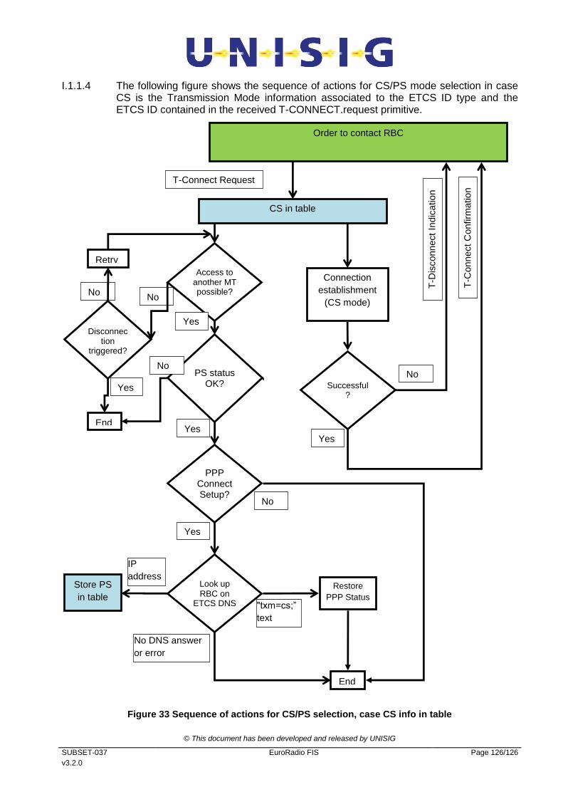
© This document has been developed and released by UNISIG
SUBSET-037
v3.2.0
EuroRadio FIS Page 126/126
I.1.1.4 The following figure shows the sequence of actions for CS/PS mode selection in case CS is the Transmission Mode information associated to the ETCS ID type and the ETCS ID contained in the received T-CONNECT.request primitive.
Figure 33 Sequence of actions for CS/PS selection, case CS info in table
No No
Order to contact RBC
CS in table
T-Connect Request
Successful?
Yes
No PS status OK?
Yes
Look up RBC on
ETCS DNS "txm=cs;”
text
No DNS answer
or error
IP
address
End
Store PS
in table
PPP Connect Setup?
Yes
No
No
Access to another MT possible?
Yes
Retry
Connection
establishment
(CS mode)
T-C
onnect C
onfirm
atio
n
T-D
isconnect In
dic
atio
n
Restore
PPP Status
Disconnection
triggered?
End
Yes