european union / instrument for pre- accession assistance
TRANSCRIPT

Consulting services for analysis of the energy storage systems CS-01.dTASK 7: Technical Specification TrainingJuly. 10/11 2019 – Ankara
Jacques LE BLEIS [email protected]
This Project is co-funded bythe European Union and the
Republic of Turkey.
European Union / Instrument for Pre-Accession Assistance
Energy Sector Program – Phase 2 Project

Technical Requirement for BESS Project Civil Work

3
Technical Requirement for BESS Project
e) Civil Work: Container (1/2)Even if some Manufacturer provide different arrangement, EDF recommend to specify a full containerized solution (Battery +
Inverter + auxiliaries inside a single container). This revels the following benefits:
Single HVAC system for inverter + Racks
Inverter more protected thanks to HVAC system (T° regulated) and protected by the general Fire suppression system
FAT with all interfaces already linked.

4
Technical Requirement for BESS Project
e) Civil Work: Container (2/2)Containerized solution shall mean an ISO maritime container of 20ft, 40ft or a container of another dimension if the Contractor chooses to have a customized container for his BESS solution.
EDF recommend the following criteria for the container itself:
Floor of the container with a fire-proofing A1
Or Externals wall, ceiling and floor with sandwich insulation panels
having a minimum of REI60.
IP54 for all equipment “at the border” ( cable gland , HVAC)
Paint of ISO norm suitable for environments of the Site
(corrosion/radiation) + life time 20years (category C3H)
2 doors ( 1 for material access + 1 standard) equipped with anti-
panic bar
Container approved by THE INTERNATIONAL CONVENTION FOR SAFE CONTAINERS (CSC)

5
Technical Requirement for BESS Project
e) Civil Work: Basement (1/3)Contractors will provide their own design for the basement of the BESS-containers: It’s not doable to force one kind of installation
as, fighting against OEM-proven standard could be counterproductive;
Typically electrical equipment suppliers will allow a differential displacement between footings of around 1cm

6
Technical Requirement for BESS Project
e) Civil Work: Basement (2/3)The following Guideline could be used to specify the Basement keeping the OEM-Standard mostly compatible:
“
Piling Require commissioned Ground Investigation works : if needed, install suitable CFA reinforced concrete piles : Preliminary topographical and geotechnical surveys for site layout and the foundation design
Slab Specify simple rectangular ground slab rather than multiple corners / install containers direct to slabs rather then elevated
Existing underground
services
Specify “pre start topo survey” in order to confirm the real location of existing underground services
Connection to the earthing grid
An earthing grid calculation (as per IEEE80) shall be carried out and extension / building of earthing grid shall be interfaced with the basement of the BESS-containers

7
Technical Requirement for BESS Project
e) Civil Work: Basement (3/3)
The following “OPTION” could be used to specify the Basement keeping the OEM-Standard mostly compatible:
Fire wall Some Manufacturer propose a Fire wall between containers to limit risk of fire spreading
Anti-flooding
In-situ access footways
In-situ access footways and slabs are to be formed by the Contractor including removal and storage on site of existing stone chippings, all excavation and removal of spoil, sand blinding, expansion/contraction joints and reinstatement.
If BESS is located on flood zone, BESS could be installed over an empty container / usually surrounding ground in line with site flooding risk and at least by around 30cm
access steps Access steps and access platforms to containerised battery and switchgear units.
Trough Wall Busbar (if any)
Connection between AC-terminals of inverters and LV-bushings of transformer could be realized by Busbar : reservation in CW shall be specified accordingly

8
Technical Requirement for BESS Project
e) Civil Work: Transformer interface + Auxiliaries CW structures are also required in order to support :
The MV/LV transformers ( if any)
The Chillers / HVAC external system (if not directly supported by the container) :
EDF advise to respect the following criteria regarding the
installation of the MV/LV transformers:
Separation from adjacent structures and from other
transformers by fire-wall or special separation(as per
§5.1.4 NFPA850)
Oil-retention tank shall be provided with design/volume
in accordance with ISO 61936-1

9
Technical Requirement for BESS Project
e) Civil Work: Cable routing (1/2) To perform a correct and complete cable routing, EDF suggest to request a full “ cable synoptic” or “external cable list” to the
contractor. This document list all cables ( I&C, main power, aux power, OF, and so on) :
Between BESS-containers
Between BESS-container and Chiller
Between BESS-container and MV/LV transformer
Between BESS-container and SCADA system
Between EMS and SCADA system
All auxiliary cables (Vdc, UPS, …)
This document is a Key-input data
in order to design the routing and
associated CW.

10
Technical Requirement for BESS Project
e) Civil Work: Cable routing (2/2) Once the cable synoptic is performed, routing can be define and correctly sized: multiple ways exist in order to lay the cables
outside:
Above ground on cable trays : recommended only for single container and in case of hard underground characteristics)
Underground in cable ducts : recommended in case of road-crossing or any existing buried service (pipe)
Underground in cable through (precast concrete) : recommended Through can also be used as access paths
20% of spare space will have to be left
available
All cable trays and conduits shall be
identified
Cable segregation : at least 250mm
between ladders
Single core cables shall be laid and bundled in trefoil
formation.
Fire and smoke stopping barriers, consisting of fire-resistant material, shall be
provided to seal all the cable entrance into container
Cables shall be fastened with metallic and galvanized cable
ties compliant with IEC 62275

Technical Requirement for BESS Project Safety

12
Technical Requirement for BESS Project
f) Safety: HVAC (1/4)HVAC system shall be provided in each BESS-container to ensure the cooling of:
The battery racks
The Inverters / Filters
Manufacturers provide 2 kinds of HVAC system:
Air- cooled
• Container is cooled by fresh air thanks to multiple Chillers• Inverters cabinets and Battery racks are cooled by air
Air + Water
• HVAC system that permits to cool down the air temperature and allows a water-cooling of the power electronic parts in the inverter
• System used for electronics above 1MVA• System require primary + secondary circuit
The SCADA / communication systems

13
Technical Requirement for BESS Project
f) Safety: HVAC (2/4)In case of 100% air-cooled system, the following specification shall be
respected :
HVAC system preferentially installed directly on the doors of the container
HVAC system shall have the following redundancy level: 2*100% Or 3*50% Or 4*33%
HVAC system shall be linked : to the main SCADA system ( Modbus or can communication) To the emergency stop management (hardware)
Manufacturer should give access to the monitoring parameters
(temperature, pressure, availability of compressors, setpoint) of the HVAC
via Local or remote HMI
The refrigerants used in the HVAC shall be free of chlorofluorocarbons
(CFCs).

14
Technical Requirement for BESS Project
f) Safety: HVAC (3/4)In case of water/air cooled system, the following specification shall be
respected :
Chillers preferentially installed on the floor of the containers or beside
directly on a small slab.
Heat exchangers +fans to be provided for the air system
Water / water exchangers and 2*100% pumps to be provided for the
inverter cooling system
The refrigerants used in the HVAC shall be free of chlorofluorocarbons
(CFCs).
Benefit of this solution:
1. allow to have 2 different T° setpoints: one for the inverter,
one for the battery racks -> energy saving
2. Secondary system can run in closed loop during fire event

15
Technical Requirement for BESS Project
f) Safety: HVAC (4/4)Whatever the selected solution, the operation of the HVAC system shall be based on the following principles:
Setpoint around 25°C for the Battery racks (to be adjusted depending on the OEM recommendations)
Main Sensitivity / threshold around 5°C (from 4 up to 7°C): this will allow to save energy but will slightly impact the
performance of the Batteries (confer T° dependency curve)
Heat threshold around 2/3°C after the main Sensitivity : basically heating will start around 12/15°C: even if capacity
increase when T° goes down, 0°C is a dangerous limit for safety (lithium plating)

16
Technical Requirement for BESS Project
f) Safety: Fire Detection (1/2)The BESS-container shall be equipped with a dedicated fire detection system.
The fire detection shall be compliant with NFPA standards, particularly 850 and 72 and the equipment shall conform to BS
EN 54 and BS EN 12094
The fire detection and suppression equipment provided by the Contractor shall include but not be limited to:
Warning labels,
Vesda detection system (or equivalent)
Visual and audible signalization devices,
Break glass push buttons,
Electrical junction boxes,
Fire detection systems.
Fire detection system shall have Modbus communication cards in order to send information to global supervision system

17
Technical Requirement for BESS Project
f) Safety: Fire Detection (2/2)To know the risks for operators and also for materials (if any corrosive gas), the Contractor shall provide fire event testing
reports on the battery technology respectively for modules and for cells incorporated into the Plant. The detail of the composition
of the venting gas shall also be provided
The behavior in case of fire detection shall be adjusted depending on
the location of the BESS-project :
If stand-alone project: a dedicated SIM-card could be added to send
direct message to the local Fire-Brigade
If located on a brownfield: best option consist into wire the BESS-
detection system to the existing global detection loop (extension) .

18
Technical Requirement for BESS Project
f) Safety: Fire Suppression System (1/3) Even if some Manufacturer (TESLA for example) do not provide any fire suppression system for the Battery racks, common
practice and good practice in order to preserve equipment and ensure a correct level of safety, EDF highly recommend to
specify a fire suppression system.
Contractor is responsibility to choose the fire suppression agent however the following elements shall be taken into account:
Minimum impact on the functionality of the system after the suppression action is over
The suppressing agent should not present any major and prolong health hazards to humans
Minimum impact on the environnement
Easy to clean

19
Technical Requirement for BESS Project
f) Safety: Fire Suppression System (2/3)
Inert Gas: FM200 Inert gas : N² Aerosol/ Powder :
Some examples from previous projects :
NOTE: the use of aerosol (for example Stat-X is not recommended as impact on material is non-negligeable)

20
Technical Requirement for BESS Project
f) Safety: Fire Suppression System (3/3) The use of suppression agent generate important warning for people and special points to take into account:
Contractor shall also provide the environmental and health impacts of the suppression agent
Contractor design shall consider evacuation of the people before injecting the suppression element in the container. Therefore,
a pre-discharge alarm and a time delay (e.g.15-30s), sufficient to allow personnel evacuation prior to discharge should be
provided
All fire protection pipes shall be insulated in order to avoid condensation if necessary
A Air-tightness test shall be conduct on site to check the insulation of the container
Coordination with HVAC system shall be provided
Over-pressure flaps shall be provided in the container.
Option: Infra-red camera and installation of automatic lamps which switch on in case of fire in the container

21
Technical Requirement for BESS Project
f) Safety: Emergency Stop Management (1/2)Different events require to stop in emergency the BESS-system:
Fire detection Emergency push Button
Eternal trip from customer
Electrical issue on the connection to the grid (including
Transformer)
In order to de-energize the container when one of this event appears, a “safety PLC” or secure emergency relays shall be
provided to interface these inputs.
The safe PLC shall be secured supplied and shall work with positive safety process: in case of lack of auxiliary voltage, system
shall trigger and trip.

22
Technical Requirement for BESS Project
f) Safety: Emergency Stop Management (2/2)In case of trip of the Safe PLC, the following CB shall be opened by the output contacts of the Safe PLC:
Main LV-CB for the BESS or each PCS-
LV-CB
DC-side of the Inverters ( in HV-
box or in PCS-cabinet)
Auxiliary supply (except the UPS
system)
Depending on the process, HVAC
system
MV-CB by the customer (option)
Additionally, contacts shall be provided in order to inform :
EMS
SCADA-system
BMS
The result of a trip shall be a container free of any voltage, except:
- UPS which stay live thanks to internal battery (to supply SCADA/
protection, and so on)
- Fire detection / protection with it’s own internal source
- Battery racks which stay live any way
- Safety lights path

23
Technical Requirement for BESS Project
f) Safety: Site ProtectionIf BESS-project is located on an existing facility (already protected by a perimeter fence), no need to specify any additional
protection.
However, the access to the BESS-container shall be limited by using :
Door sensors on each door : during Operation, if open, this shall generate a specific alarm
Specific padlock on each door to secure the installation during SAT ( safety issue) and during operation.
If BESS-project is located on an stand-alone plot, the Owner shall specify its own habitual practice for site :
security perimeter fence of total height XXm from finished ground level ( + double corrosion protection)
The fence shall be stable and able to withstand a wind speed of 160 km/hr and a vehicle crash as per applicable international
standards.
All fencing have to be properly connected to an earthing grid
Camera to be provided on the main Gate for the site (linked to the SCADA-system)

24
Technical Requirement for BESS Project
f) Safety: Environmental Impact Except I&C and Power interfaces, BESS-project do not require any specific interface with facilities/ environment:
WATER GAS/ FUEL Connection
GASOUT EFFLUENT
LIQUID EFFLUENT
NOISE LEVEL TO SPECIFY: <60dB outside of each container OR limit at
site boundary to speficy

Supply chain: selection of the OEMs

26
Supply Chain : selection of OEMs
a) Battery Supplier (1/7)The selection of the Battery Manufacturer shall be based on the following criteria:
Battery shall have a minimum 2-year warranty covering defects and workmanship that provides for all shipping costs, parts or
repair warranty-eligible failures.
Choice of the battery technology, supplier and manufacturing line is subject to approval by the Owner
At least one Audit (during Bidding stage) shall be carried out by the Owner + specific consultant directly in the Battery-Factory
Final clarification / Audit report transmitted not later than 6 months before expected date for purchase order of Batteries
Regarding the Battery itself, Data and information coming from the supplier are not based on specific
International standard; that’s why it could be difficult to align the different suppliers (various test conditions)
WAR
NIN
G
Regarding the Battery itself, Data and information coming from the supplier could be “subjective” and do not fully
stick to the “reality” or the needs/expectation of the projects

27
Supply Chain : selection of OEMs
a) Battery Supplier (2/7)The Audit to be performed by the Battery Manufacturer shall contain the following criteria for the process:
Electrode Fabrication
• No major difference bwn suppliers seen on previous projects
Assembling• High Energy density by stacking vs winding
Formation / Aging
• Stable structure by stacking
28
Supply Chain : selection of OEMs
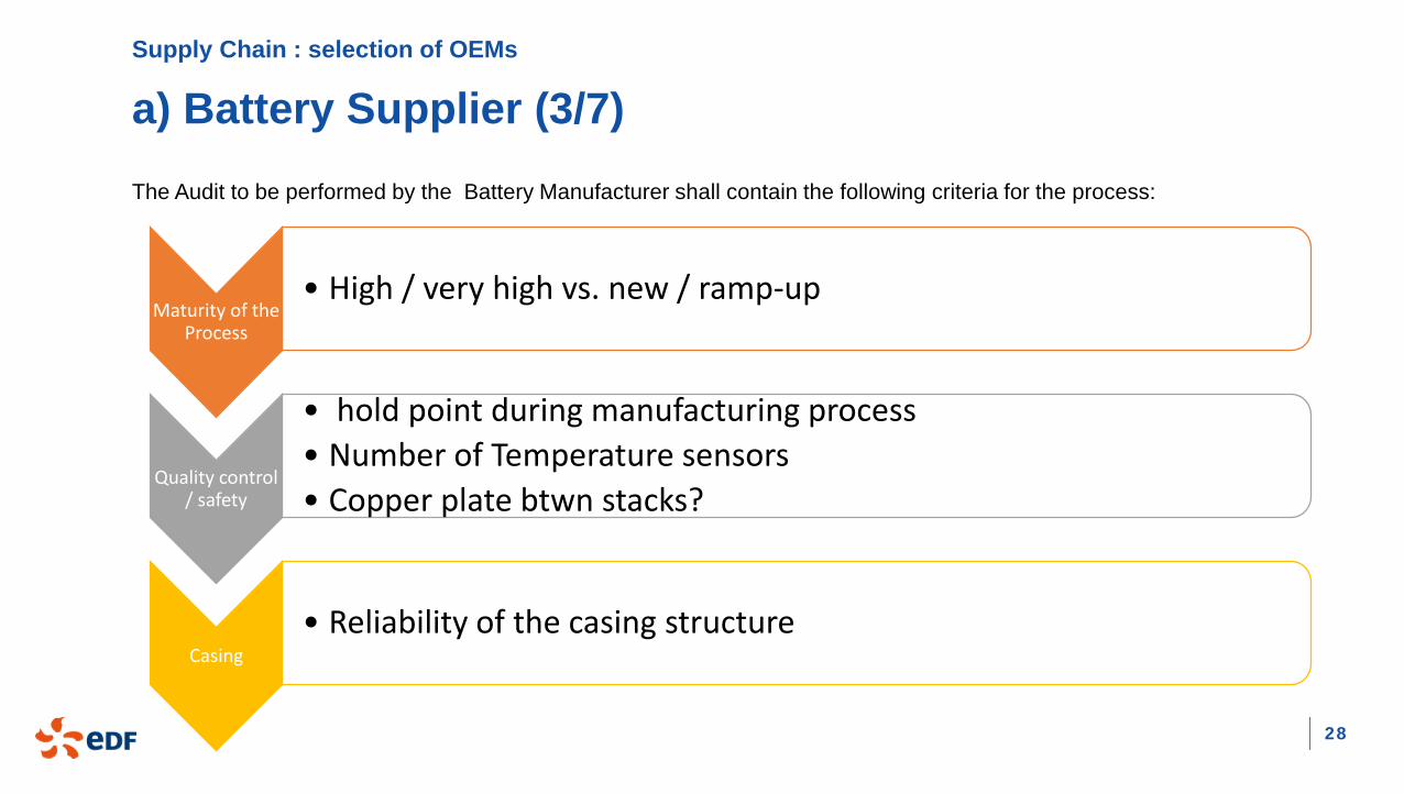
a) Battery Supplier (3/7)
Maturity of the Process
• High / very high vs. new / ramp-up
Quality control / safety
• hold point during manufacturing process• Number of Temperature sensors• Copper plate btwn stacks?
Casing• Reliability of the casing structure
The Audit to be performed by the Battery Manufacturer shall contain the following criteria for the process:

29
Supply Chain : selection of OEMs
a) Battery Supplier (4/7)Additionally, the Audit to be performed by the Battery Manufacturer shall contain the following items:
Material management
Procurement & sub-supplier management
Corrective action & Non-conforming process + process improvement
Training
Corporate social responsibility , environmental , health & safety
Based on all these criteria, a specific ranking
is established to sort out a preferred supplier:

30
Supply Chain : selection of OEMs
a) Battery Supplier (5/7)
As mentioned, performance and data published by manufacturers do not always revel the real state and capability of the cells.
EDF highly recommend to perform specific sample test for the targeted application.
As an example, EDF ran its own test on sample modules in order to check the real performances:

31
Supply Chain : selection of OEMs
a) Battery Supplier (6/7)
As mentioned during EDF Site visit in February 2019, EDF is able to perform such a “ 3rd party” tests to validate the Battery
supplier
This allow to secure the project ( or not) :
- by confirming the capabilities of the cells for the project
use case
- By challenging the margin taken by the contractor

32
Supply Chain : selection of OEMs
a) Battery Supplier (7/7)
Owner shall keep in mind that the Battery supplier will also provide (non-exhaustive list) :
Rack to insert the Module
Battery Management system (BMS)
HV-box to protect the Battery strings
Ventilation system within the racks.
As a consequence, these equipment shall also be part of the Audit / Selection process
Suppliers from previous projects :
NARADA, LG,
SAMSUNG

33
Supply Chain : selection of OEMs
b) Inverter Supplier Inverters shall be selected with care as they are potentially an important cause of unavailability for the project . As comparison,
around 50% of the unavailability for PV-plant is caused by fault on the inverters itself.
In order to secure this topic, EDF recommend to include the following criteria in the requisition or specification:
Manufacturer shall have a manufacturing capacity of at least XXX MW/year ( example 100MW/year)
Manufacturer shall have been manufacturing power converters for at least XX years; ( example 5 years)
At least XXX MW capacity of the proposed PCS shall be in operation for at least one year. (example 50MW)
Accredited testing laboratory for the required certificates
OPTION: carry out an Audit directly by the
Inverter-supplier to confirm the compliance
Suppliers from previous projects :
NIDEC, SIEMENS,
GE

34
Supply Chain : selection of OEMs
c) BESS Contractor (Integrator) The main contractor for BESS will build up the containers thanks to the Battery supplier and Inverter supplier. This one will lead
the project and will be in charge of the whole coordination with HVAC, auxiliaries, Civil work, EMS and SCADA.
In order to secure this topic, EDF recommend to include the following criteria in the requisition or specification:
BESS-main contactor shall have proven successful operation in utility-scale installation
BESS-main contactor has supplied at least XXMW – XXhrs/mins of operational projects and not less than three (3) operational
projects of at least 1 MW.
BESS-main contactor shall have proven successful operation in targeted operation (i.e. fast frequency response)
If EMS and SCADA is provided by the BESS-Contractor,
additional requirement for these equipment shall be
requested (SIL-level, copy of previous SCADA system,
skills of development department, and so on)
Suppliers from previous projects :
NIDEC, NARADA
GE

Frequency Containment Reserve (FCR)

36
Frequency Containment Reserve (FCR)
a) Definition of System / Metering Strategy (1/7)In order to define ( from the client point of view) a dynamic service for frequency response, EDF strongly recommend to base the
requirement on the guidance documents provided by National Grid (UK) for their Bid; these documents are available on the
following link :
https://www.nationalgrideso.com/balancing-services/frequency-response-services/enhanced-frequency-response-efr?technical-
requirements
The key document/diagram to be provided for describing the service are :
Definition of the Delivery Envelopes
(service)
Definition of the ramp rate, max
service duration, response time
Extract of the existing frequency
database
Performance criteria Metering

37
Frequency Containment Reserve (FCR)
a) Definition of System / Metering Strategy (2/7)One key document is the definition of the Service Envelope; this one fix the static requirement of a frequency service
(proportional response to a change in system frequency) by :
Showing the upper, lower and reference profile : assets must ensure their output is within the upper and lower envelopes at all
times
Defining the Deadband: Within this range the active power of the assets does not need to respond proportionally to the system
frequency This is really important in order to reset the SOC of the BESS system at 50%, after a frequency event
Sensitivity ( narrow or wide profile) is based on the study of the f-data base of the gridarea.
38
Frequency Containment Reserve (FCR)
a) Definition of System / Metering Strategy (2/7)For the BESS-supplier, there are multiple technical criteria to define in order to lock the reliability of the system and the quality of
the algorithms:
Response’s time of the system: < 1sec (example); Owner shall explicate the wording “ response’s time”: basically this term is
a overall time (whole loop) which include: measuring + response’s time of the meter : around 500ms for the frequency measurement (sampling rate around 100ms) Communication time (server / input-output cards) SCADA treatment time (including algorithm) Response’s time of the Inverters measuring + response’s time of the output meter
Duration of the service (worst case): 10/ 15 / 30 min (or more) this is a key criteria to size the BESS stored energy
Defining the Deadband: Within this range the active power of the assets does not need to respond proportionally to the system
frequency is allow to charge / discharge within the XX% power tolerance

39
Frequency Containment Reserve (FCR)
a) Definition of System / Metering Strategy (3/7)For the BESS-supplier, there are multiple technical criteria to define in order to lock the reliability of the system and the quality of
the algorithms:
Maximal/Minimal slope computation of the system:
Such a limit is necessary to avoid excessive damping
and ensure stability on the grid.
Maximal Over/undershoot deviation: usually <1or 2% of the
rated power: response will stick to the frequency deviation even
during transient behavior
Stationary Accuracy : usually <1or 2% of the rated power:
response will stick to the frequency deviation even during steady state behavior

40
Frequency Containment Reserve (FCR)
a) Definition of System / Metering Strategy (4/7)The rated capacity of BESS-project is depending on :
the duration of the service (confer to previous slide)
The number of equivalent cycles/year that BESS will
ensure. When the service is Frequency deviation, this
number could be estimated/confirmed by BESS-
supplier thanks to the historical frequency data.
The requested life-time of the project : 10 / 15years
These 3 criteria will generate an over-size of the rated
capacity at T0 in order to be able to provide the service at
the end of the life time (considering the aging of Battery
module and cycling) : typically a factor 1,1 or 1,2

41
Frequency Containment Reserve (FCR)
a) Definition of System / Metering Strategy (5/7)The life-time of the BESS will not be only define by a theoretical value (5/10/15years); this value shall be yearly controlled an
monitor by :
Specifying a yearly minimum value for the SOH (State Of Heath) of the system in a Table:
Specifying a yearly minimum AC/AC round trip efficiency (at POC)
of the system in a dedicated Table (typical value 80% after 10 years)

42
Frequency Containment Reserve (FCR)
a) Definition of System / Metering Strategy (6/7)The BESS-supplier shall also be responsible of the availability of the system.
To preserve the owner from bad-quality equipment, not-reliable algorithm, unappropriated Maintenance schedule and so on, EDF
recommend to specify a minimum availability rate to achieve each year :
This rate is based on the “service performance measurement” (confer part b)).
Typically, BESS-project could achieve 95%
availability rate (or more if very strictly specified but
with over costs)

43
Frequency Containment Reserve (FCR)
a) Definition of System / Metering Strategy (7/7)EDF recommend to specify :
One dedicated frequency meter at the POC with: redundant channel a measurement error < 0,01Hz
Two meter (main and back-up) for the power (active and reactive) measurement with: Class 0,2S category Hardware output + Modbus / 61850 communication channel
CT and VTs required for metering purpose shall be : Class 0,2 category (IEC60044) 1A secondary for CT 100V/square(3) for VT
Meter shall be installed in a dedicated cubicle which will be :
Tested on site by Grid operator ( witness point)
Sealed by grid operator (after SAT completion)

44
Frequency Containment Reserve (FCR)
b) Monitoring of the Performance (1/2)The performance score of the plant is computed using three
indicators:
The second by second performance measure, (SBSPM) is
computed using a template with deviation lines
The service performance measure (SPM) is the average
over 30min of the SBSPM
Finally, the availability factor is computed from the SPM
using different timeslot.

45
Frequency Containment Reserve (FCR)
b) Monitoring of the Performance (2/2)Based on these performance score of the plant, the owner shall define potential penalties to be applied to the BESS-supplier if
the contractual minimal performance (availability rate) are not reached.
Additionally, in case of long time period of unavailability ( more than 30mi for example), the BESS-supplier ( or entity in charge of
operating the BESS) shall produce a specific report which mention:
The rectification of capability
The explanation of rectification
The grid operator shall have a direct access (either by data-center or via meter-link) in order to double check
the reliability of these score.

46
Frequency Containment Reserve (FCR)
c) Tests profils (1/3)The Owner shall define test-profile to be performed during SAT in order to demonstrate the compliance of the regulation’s law of
the BESS. Basically, the purpose of theses profiles is to test 3 requirements :
the system time response
the power behavior of the system with the evolution of the frequency over the complete range
the maximal EFR power maximal delivery duration
Step Test: goal is to check:
The response time of the system
The system behavior in the dead band,
The proportionality of the response in the
collapsed regions

47
Frequency Containment Reserve (FCR)
c) Tests profils (2/3)
Frequency Sweep Test: goal is to check:
fulfillment of the power Vs frequency template
48
Frequency Containment Reserve (FCR)
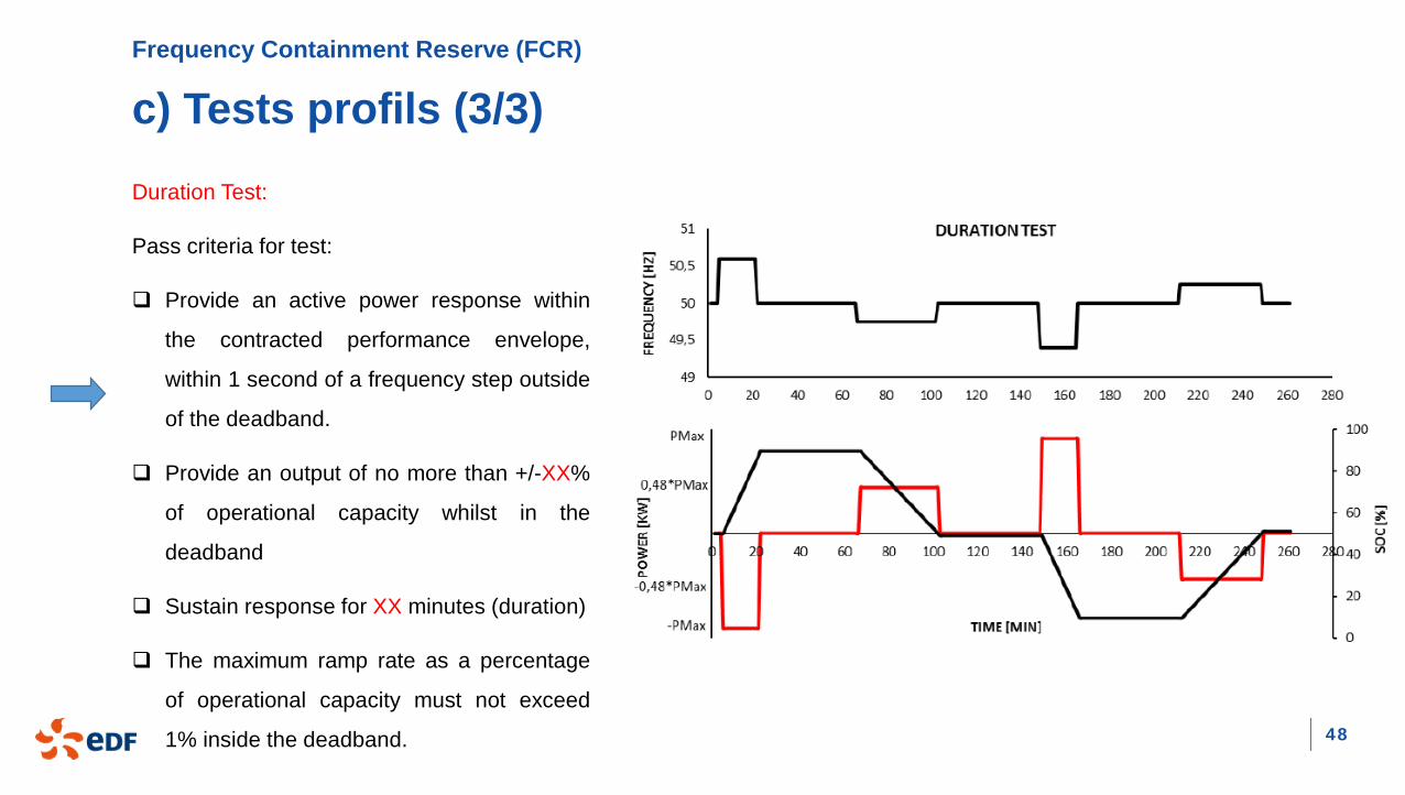
c) Tests profils (3/3)Duration Test:
Pass criteria for test:
Provide an active power response within
the contracted performance envelope,
within 1 second of a frequency step outside
of the deadband.
Provide an output of no more than +/-XX%
of operational capacity whilst in the
deadband
Sustain response for XX minutes (duration)
The maximum ramp rate as a percentage
of operational capacity must not exceed
1% inside the deadband.

Erection / Commissioning

50
Erection / Commissioning
a) Construction Guideline (1/7)
In order to secure the project, EDF strongly advise to ship the container with the
inverters already inside in order to avoid trouble during erection on site (confer to
previous project). Furthermore, this allow to test the inverters interfaces during FAT
(with BMS / SCADA).
A STRICT WORK FLOW
RA + MSby
Contractor
Validation by
Owner
Work Orderby
Interface team
Safety Assessment
(SAP)
Permit to Work(SAP)
To ensure a sufficient level of safety on site, EDF is used to establish HSE and site rules during construction phase; First stage
of safety is performed by the contractor itself by providing 2 weeks in advance a “RAMS” for each task : Risk Assessment and
Method Statement.
51
Erection / Commissioning
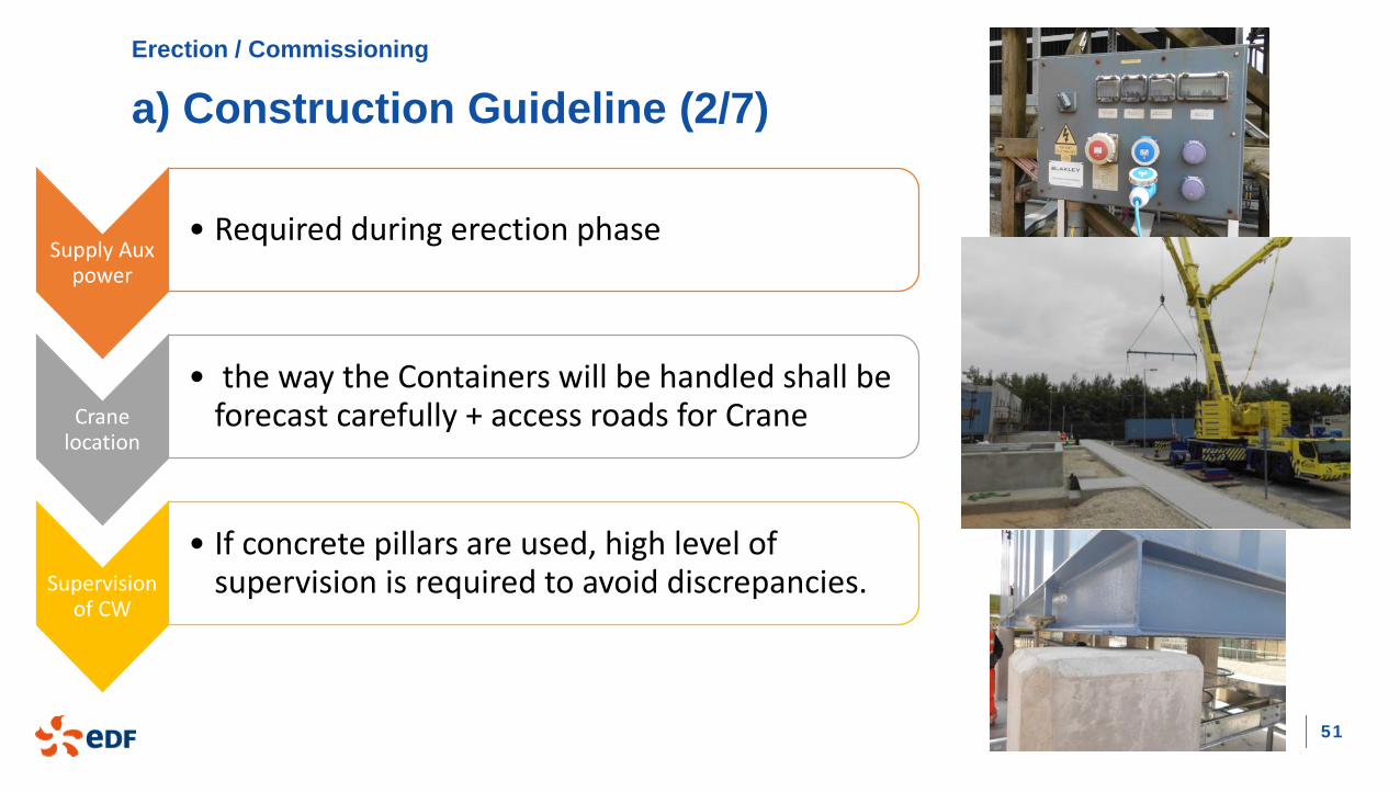
a) Construction Guideline (2/7)
Supply Aux power
• Required during erection phase
Crane location
• the way the Containers will be handled shall be forecast carefully + access roads for Crane
Supervision of CW
• If concrete pillars are used, high level of supervision is required to avoid discrepancies.

52
Erection / Commissioning
a) Construction Guideline (3/7)
Compliance Survey
• During first phase of construction: perform an independent pre-inspection to check the compliance with IEC/Local rules
Concrete quality check
• before starting CW, run a concrete quality check (Contractor source from the cheapest provider)
Cable pulling
• Bending radius for MV/LV cables shall be respected during pulling

53
Erection / Commissioning
a) Construction Guideline (4/7)
Waste Management
• Battery module unpacking generate high volume of waste ; Owner shall describe the recycling stream
Handling the battery
• Each module could weigh from 20kg up to 50kg, thousands of module will have to be handle in the racks; suitable equipment shall be forecast to avoid harm

54
Erection / Commissioning
a) Construction Guideline (5/7)
Safety for O&M
• During first phase of construction, EDF recommend a survey by O&M-part oriented safety for operators; they will build a snag-list and anticipation will avoid blocking points during transfer
Build a “non conformance list”
• During the whole construction phase, a non-conformance list shall be updated and action tracker ( each week) shall be established.

55
Erection / Commissioning
a) Construction Guideline (7/7)
Labeling
• Key point for correct RAMS, permit, coordination is the labeling of equipment; • all internal equipment shall be correctly labeled ( with
single TAG) before shipment• All equipment installed on site (cable) shall be labelled
before starting SAT
DC-Safety for Battery racks
• Once completely wired, the DC-string voltage reach around 900Vdc. As per IEC 61558, Safety extra low voltage (SELV) is only 120Vdc that’s why strict rules shall be established during connection copper bar screwing operation

56
Erection / Commissioning
b) Commissioning Guideline (1/6)
A STRICT FIRST ENERGIZATION
Mechanical completion
No blocking snag
Ground + insulation
report produced (IEC
rules)
Run emergency trip tests + Fire
detection
Real tests for the Grid
protection (with Asbuild
selectivity study)
Documentation updated + Grid
Permit
First Energization of the BESS-container is a critical step. The following tasks shall be realized ( with report) to authorize the first
energization:
This procedure shall be validated by Customer, Owner, Contractor and Grid operator. From this step,
BESS is connected to the grid and may potentially impact negatively the Grid if procedure is not
performed correctly.

57
Erection / Commissioning
b) Commissioning Guideline (2/6)The Site Acceptance Tests will break down into multiple procedures:
Battery BMS Inverters Auxiliaries SCADA EMS
Battery-module Rack
HV-box (including
disconnector) DC-link+ cables
BMSSignals
Communication + control functions
Aux supplyAccuracy tests
Alarm level
Cold CommissioningInterface with SCADA/ BMSPerformance
testsGrid
requirements (LVRT, cut-off) Dynamic testsSpecial mode
tests
emergency stop management
HVACFire detection Fire protection Air tightness
testsUPS tests
lighting
HMILocal / remote
control Special modeInterface with
EMSReactive
capabilitiesSOC
management
EMS algorithm Test profils
Communication with Data center
Customer interfaces
Meter interfaces

58
Erection / Commissioning
b) Commissioning Guideline (3/6)
Design for Test purpose
• Test of the protection function require specific test plug on: • The protection relay in the MV-cells• The inverter itself for the LV-side.
Interface with Fire detection / protection
• An air tightness test is required to demonstrate the capability of each container
• Fire detection must operate as soon as SAT start; Protection could be inhibited to avoid inadvertent trip during SAT

59
Erection / Commissioning
b) Commissioning Guideline (4/6)
Profile Test
• The Profile tests (required by Gird operator) shall be performed via the EMS: this will validate the whole control loop and state the performance of the global system
Interface with customer (if any) or
with grid during tests
• When active / reactive capability tests are performed, this will impact the frequency and voltage level at the POC (customer or Grid). That’s why preliminary acceptance by customer or Grid shall be agreed.

60
Erection / Commissioning
b) Commissioning Guideline (5/6)
Calibration of major signals
• Special care for the calibration of major signals: SOC, power (active and reactive). Those signals are build via multiple layers (BMS/PCS/SCADA/EMS) -> ensure the final signal is coherent
Sharing and Support for each
tasks
• For each task on the SAT-program, the sharing of responsibilities shall be clearly stated : • Team test = ? • Supporting team =? • Owner witness point?
.
Identify and engage Key-stakeholders
as soon as possible
Profile test require everybody to
adjust parameter “in live” (BMS,
Inverter, SCADA, EMS)

61
Erection / Commissioning
b) Commissioning Guideline (6/6)
Change Management
• Special warning regarding the “change control”. The lack of change control for SCADA / EMS parameter as it’s modified on site is not picked up in live ( or not at all). The tracking of these changes will help understand how software has been modified and also help if any issues later arise.
Good Practice for ending SAT
• Takeover certificates signed by all contributors (including SAT-reports in annex)
• Conduce an XX proving days test to state the performance in real conditions of the system
.
List of all settings to be checked
during SAT
Copy of HMI-view
Copy of logic-diagram

Teşekkür ederim

63
SOURCE
Reference/ pictures• National Grid: https://www.nationalgrideso.com/balancing-services/frequency-response-services/enhanced-frequency-
response-efr?technical-requirements
• BDEW guideline: https://www.bdew.de/service/stellungnahmen/guideline-electricity-balancing/