european technical assessment eta-06/0106 of...
TRANSCRIPT
ETA-Danmark A/S Göteborg Plads 1 DK-2150 Nordhavn Tel. +45 72 24 59 00 Fax +45 72 24 59 04 Internet www.etadanmark.dk
Authorised and notified according to Article 29 of the Regulation (EU) No 305/2011 of the European Parliament and of the Council of 9 March 2011
MEMBER OF EOTA
European Technical Assessment ETA-06/0106 of 24/05/2017
I General Part
Technical Assessment Body issuing the ETA and designated according to Article 29
of the Regulation (EU) No 305/2011: ETA-Danmark A/S
Trade name of the
construction product:
Simpson Strong-Tie Angle Brackets See type numbers in section II.1 of the ETA
Product family to which
the above construction
product belongs:
Three-dimensional nailing plate (timber-to-timber/timber-to-concrete angle bracket)
Manufacturer: Simpson Strong-Tie Int. Ltd For local branch addresses refer to www.strongtie.eu
Manufacturing plant: SIMPSON STRONG-TIE Manufacturing facilities
This European Technical
Assessment contains:
334 pages including 4 annexes which form an integral part of the document
This European Technical
Assessment is issued in
accordance with
Regulation (EU) No
305/2011, on the basis of:
Guideline for European Technical Approval (ETAG) No. 015 Three Dimensional Nailing Plates, April 2013, used as European Assessment Document (EAD).
This version replaces:
The ETA with the same number issued on 2016-12-06
Page 2 of 334 of European Technical Assessment no. ETA-06/0106, issued on 2017-05-24
II SPECIAL CONDITIONS OF THE EUROPEAN TECHNICAL ASSESSMENT ................. 5
1 TECHNICAL DESCRIPTION OF PRODUCT AND INTENDED USE .................................................................................. 5 2 SPECIFICATION OF THE INTENDED USE IN ACCORDANCE WITH THE APPLICABLE EAD .......................................... 5 3 CHARACTERISTICS OF PRODUCT AND ASSESSMENT ................................................................................................ 7 4 ASSESSMENT AND VERIFICATION OF CONSTANCY OF PERFORMANCE (AVCP) .................................................... 10 5 TECHNICAL DETAILS NECESSARY FOR THE IMPLEMENTATION OF THE AVCP SYSTEM, AS FORESEEN IN THE
APPLICABLE EAD ......................................................................................................................................................... 10
ANNEX A - REVISION HISTORY ................................................................................................. 11
ANNEX B - TYPICAL INSTALLATION ........................................................................................ 14
ANNEX C - BASIS OF DESIGN .................................................................................................... 18
ANNEX C1 – BASIS OF DESIGN .................................................................................................................................... 18 ANNEX C2 – DEFINITION OF FORCES DIRECTION ......................................................................................................... 19 ANNEX C3 – FASTENERS SPECIFICATION AND CAPACITIES ......................................................................................... 23 ANNEX C4 – CHARACTERISTIC CAPACITY MODIFICATION METHODS FOR NAILS AND TIMBER TYPES ......................... 24
ANNEX D - PRODUCT DEFINITION AND CAPACITIES ......................................................... 26
ANNEX D1 – ABR90 .................................................................................................................................................... 27 ANNEX D2 – AB90 ....................................................................................................................................................... 36 ANNEX D3 – ABR105 .................................................................................................................................................. 42 ANNEX D4 – AB105 ..................................................................................................................................................... 51 ANNEX D5 – ABR70 .................................................................................................................................................... 57 ANNEX D6 – AB70 ....................................................................................................................................................... 64 ANNEX D7 – E20/3 ....................................................................................................................................................... 66 ANNEX D8 – E9/2.5 ...................................................................................................................................................... 74 ANNEX D9 – E9S/2.5 ................................................................................................................................................... 79 ANNEX D10 – ABR9015 .............................................................................................................................................. 84 ANNEX D11 – ABR9020 .............................................................................................................................................. 89 ANNEX D12 – ABR100 ................................................................................................................................................ 98 ANNEX D13 – AA60280 ............................................................................................................................................ 103 ANNEX D14 – ABB40390 .......................................................................................................................................... 105 ANNEX D15 – AE48 ................................................................................................................................................... 109 ANNEX D16 – AE76 ................................................................................................................................................... 114 ANNEX D17 – AE116 ................................................................................................................................................. 120 ANNEX D18 – AG40312, AG40412, AG40314 & AG40414 ..................................................................................... 128 ANNEX D19 – AH9035 .............................................................................................................................................. 136 ANNEX D20 – AJ60416 .............................................................................................................................................. 138 ANNEX D21 – AJ80416 .............................................................................................................................................. 140 ANNEX D22 – AJ99416 .............................................................................................................................................. 142 ANNEX D23 – KNAG90, 130, 170 & 210 .................................................................................................................. 144 ANNEX D24 – ES10 & ES11 ...................................................................................................................................... 150 ANNEX D25 – LS30, LS50, LS70 & LS90 ................................................................................................................. 158 ANNEX D26 – TA9Z & TA10Z .................................................................................................................................. 161 ANNEX D27 – ABR170 & ABR 220 .......................................................................................................................... 163 ANNEX D28 – AB6983 ............................................................................................................................................... 168 ANNEX D29 – AB36125 ............................................................................................................................................. 170 ANNEX D30 – BNV33 ................................................................................................................................................ 173 ANNEX D31 – E5/1.5 .................................................................................................................................................. 175 ANNEX D32 – E5/2 ..................................................................................................................................................... 184 ANNEX D33 – AT1 ..................................................................................................................................................... 190 ANNEX D34 – E4/2.5 .................................................................................................................................................. 197 ANNEX D35 – E6/2 ..................................................................................................................................................... 202 ANNEX D36 – E6/2,5 .................................................................................................................................................. 210 ANNEX D37 – E7/2,5 .................................................................................................................................................. 218
Page 3 of 334 of European Technical Assessment no. ETA-06/0106, issued on 2017-05-24
ANNEX D38 – E8/2,5 .................................................................................................................................................. 227 ANNEX D39 – E14/2 ................................................................................................................................................... 236 ANNEX D40 – E17/2 ................................................................................................................................................... 240 ANNEX D41 – E18/2,5 ................................................................................................................................................ 248 ANNEX D42 – E19/3 ................................................................................................................................................... 256 ANNEX D43 – ADR6090 ............................................................................................................................................ 265 ANNEX D44 – ADR6035 ............................................................................................................................................ 268 ANNEX D45 – ABAI105............................................................................................................................................. 270 ANNEX D46 – AG922 ................................................................................................................................................ 272 ANNEX D47 – ABR10525 .......................................................................................................................................... 276 ANNEX D48 – ABR7015 ............................................................................................................................................ 282 ANNEX D49 – ACR / ACRL ...................................................................................................................................... 285 ANNEX D50 – MAXIMUS ......................................................................................................................................... 291 ANNEX D51 – AT2 ..................................................................................................................................................... 294 ANNEX D52 – ABR865 .............................................................................................................................................. 296 ANNEX D53 – ACFET200 & ACFET200PP .............................................................................................................. 299 ANNEX D54 – ANP .................................................................................................................................................... 300 ANNEX D55 – A-BRACKETS ....................................................................................................................................... 304 ANNEX D56 – ABR98 & ABRL98 ............................................................................................................................. 309 ANNEX D57 – AB105/513 .......................................................................................................................................... 311 ANNEX D58 – ABR255 .............................................................................................................................................. 313 ANNEX D59 – ABD45100 & ABDW45100 ............................................................................................................... 319 ANNEX D60 – ADR6090L ......................................................................................................................................... 322 ANNEX D61 – ABTR120/180/240 ............................................................................................................................. 325 ANNEX D62 – ACW155 ............................................................................................................................................. 329 ANNEX D63 – AE90-RW ........................................................................................................................................... 333

Page 4 of 334 of European Technical Assessment no. ETA-06/0106, issued on 2017-05-24
Translations of this European Technical
Assessment in other languages shall fully
correspond to the original issued document and
should be identified as such.
Communication of this European Technical
Assessment, including transmission by electronic
means, shall be in full (excepted the confidential
Annex(es) referred to above). However, partial
reproduction may be made, with the written consent
of the issuing Technical Assessment Body. Any
partial reproduction has to be identified as such.
Page 5 of 334 of European Technical Assessment no. ETA-06/0106, issued on 2017-05-24
II SPECIAL CONDITIONS OF THE
EUROPEAN TECHNICAL
ASSESSMENT
1 Technical description of product and
intended use
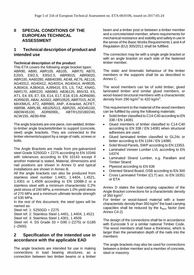
Technical description of the product This ETA covers the following angle bracket types: ABR90, AB90, ABR105, AB105, ABR70, AB70, E20/3, E9/2.5, E9S/2.5, ABR9015, ABR9020, ABR100, AA60280, ABB40390, AE48, AE76, AE116, AG40312, AG40412, AG40314, AG40414, AH9035, AJ60416, AJ80416, AJ99416, ES, LS, TAZ, KNAG, ABR170, ABR220, AB6983, AB36125, BNV33, E5, AT1, E4, E6, E7, E8, E14, E17, E18, E19, ADR6090, ADR6035, ABAI, AG922, ABR10525, ABR7015, ACR, MAXIMUS, AT2, ABR865, ANP, A-bracket, ACFET, ABR98, ABRL98, AB105/513, ABR255, ADD45100, ABDW45100, ADR6090L, ABTR120/180/240, ACW155, AE90-RW. The angle brackets are one piece, non-welded, timber-to-timber angle brackets/timber to support (concrete, steel) angle brackets. They are connected to the timber elements/support by a range of nails, screws or bolts. The Angle Brackets are made from pre-galvanized steel Grade S250GD + Z275 according to EN 10346 with tolerances according to EN 10143 except if another material is stated. Material, dimensions and nail positions are shown in Annex D and typical installations are shown in Annex B. All the angle brackets can also be produced from stainless steel number 1.4401, 1.4404, 1.4521, 1.4301 or 1.4509 according to EN 10088-2 or a stainless steel with a minimum characteristic 0.2% yield stress of 240 MPa, a minimum 1.0% yield stress of 270 MPa and a minimum ultimate tensile strength of 530 MPa. In the rest of this document, the steel types will be named as: Steel ref. 1: S250GD + Z275 Steel ref. 2: Stainless Steel 1.4401, 1.4404, 1.4521 Steel ref. 3: Stainless Steel 1.4301, 1.4509 Steel ref. 4: SS Grade 33 + G90 (~Z275) or G185 (~Z600)
2 Specification of the intended use in
accordance with the applicable EAD
The angle brackets are intended for use in making connections in load bearing structures, as a connection between two timber beams or a timber
beam and a timber post or between a timber member and a concrete/steel member, where requirements for mechanical resistance and stability and safety in use in the sense of the Basic Works Requirements 1 and 4 of Regulation (EU) 305/2011 shall be fulfilled. The connection may be with a single angle bracket or with an angle bracket on each side of the fastened timber member. The static and kinematic behaviour of the timber members or the supports shall be as described in Annex C. The wood members can be of solid timber, glued laminated timber and similar glued members, or wood-based structural members with a characteristic density from 290 kg/m3 to 420 kg/m3. This requirement to the material of the wood members can be fulfilled by using the following materials:
Solid timber classified to C14-C40 according to EN 338 / EN 14081
Glued members of timber classified to C14-C40 according to EN 338 / EN 14081 when structural adhesives are used.
Glued laminated timber classified to GL24c or better according to EN 1194 / EN 14080.
Solid Wood Panels, SWP according to EN 13353.
Laminated Veneer Lumber LVL according to EN 14374
Laminated Strand Lumber, e.g. Parallam and Timber Strand
Plywood according to EN 636
Oriented Strand Board, OSB according to EN 300
Cross Laminated Timber (CLT) acc. to EN 16351 or ETA
Annex D states the load-carrying capacities of the Angle Bracket connections for a characteristic density of 350 kg/m3. For timber or wood-based material with a lower characteristic density than 350 kg/m3 the load-carrying capacities shall be reduced by the kdens factor (see Annex C4-2) The design of the connections shall be in accordance with Eurocode 5 or a similar national Timber Code. The wood members shall have a thickness, which is larger than the penetration depth of the nails into the members The angle brackets may also be used for connections between a timber member and a member of concrete, steel or masonry.

Page 6 of 334 of European Technical Assessment no. ETA-06/0106, issued on 2017-05-24
The angle brackets are primarily for use in timber structures subject to the dry, internal conditions defined by service class 1 and 2 of Eurocode 5 and for connections subject to static or quasi-static loading. The angle brackets can also be used in outdoor timber structures, service class 3, when a corrosion protection in accordance with Euro Code 5 is applied, or when stainless steel with similar or better characteristic yield and ultimate strength is employed. The scope of the hangers regarding resistance to corrosion shall be defined according to national provisions that apply at the installation site considering environmental conditions and in conjunction with the admissible service conditions according to EN 1995-1-1 and the admissible corrosivity category as described and defined in EN ISO 12944-2 The provisions made in this European Technical Assessment are based on an assumed intended working life of the angle brackets of 50 years. The indications given on the working life cannot be interpreted as a guarantee given by the producer or Assessment Body, but are to be regarded only as a means for choosing the right products in relation to the expected economically reasonable working life of the works.

Page 7 of 334 of European Technical Assessment no. ETA-06/0106, issued on 2017-05-24
3 Characteristics of product and assessment
Characteristic
Assessment of characteristic
3.1 Mechanical resistance and stability*) (BWR1)
Characteristic load-carrying capacity
See Annex D
Stiffness
No performance determined
Ductility in cyclic testing
No performance determined
3.2 Safety in case of fire (BWR2)
Reaction to fire
The angle brackets are made from steel
classified as Euroclass A1 in accordance with EN 13501-1 and EC decision 96/603/EC, amended by EC Decision 2000/605/EC
3.3 Hygiene, health and the environment (BWR3)
Influence on air quality
The product does not contain/release dangerous substances specified in TR 034, dated March 2012
3.7 Sustainable use of natural resources (BWR7)
Not relevant
3.8 General aspects related to the performance
of the product
The angle brackets have been assessed as having satisfactory durability and serviceability when used in timber structures using the timber species described in Eurocode 5 and subject to the dry internal conditions defined by service class 1, 2 and 3
Identification
See Annex D
*) See additional information in section 3.9 – 3.12.

Page 8 of 334 of European Technical Assessment no. ETA-06/0106, issued on 2017-05-24
3.9 Methods of verification
Safety principles and partial factors The characteristic load-carrying capacities have been calculated considering different ratios between the partial factors for timber connections and steel cross sections. According to clause 6.3.5 of EN 1990 (Eurocode – Basis of structural design) the characteristic resistance for structural members that comprise more than one material acting in association should be calculated as
d
im
m
iikik
M
d aXXRR ;;1
,
1.
)1(,1,1
1,
where 1,M is the global partial factor for material 1
(in this case wood), 1,m is the partial factor on the
material and im, are material partial factors for the
other materials, i.e. the calculations are made with material parameters modified by multiplication by
kmodi = imm ,1,
The characteristic load-carrying capacities have been calculated considering a ratio between the partial factor for timber connections and steel cross sections
18,1dimok ( 18,110,1
30,1:5 dimokEC )
For kmodi> 1,18 the load-carrying capacities stated in Annex D are valid (on the safe side). For kmodi<1,18 the load-carrying capacities stated in Annex D have to be multiplied by a factor
18,1
dimokf
3.10 Mechanical resistance and stability See annex D for characteristic load-carrying capacity in the different directions F1 to F5. The characteristic capacities of the angle brackets are determined by calculation assisted by testing as described in the EOTA Guideline 015 clause 5.1.2. They should be used for designs in accordance with Eurocode 5 or a similar national Timber Code. No performance has been determined in relation to ductility of a joint under cyclic testing. The contribution to the performance of structures in seismic zones, therefore, has not been assessed.
For some Angle Brackets, the performance has been determined in relation to the joint’s stiffness properties - to be used for the analysis of the serviceability limit state.
Fasteners The load bearing capacities of the brackets have been determined based on the use of Connector nails CNA or connector screws CSA in accordance with ETA-04/0013. It is allowed to use other connector nails or connector screws in accordance with the standard EN 14592 with the same or better performance than the used 4,0 mm CNA Connector nails and still achieve the same load-bearing capacity of the connection. For some brackets the load bearing capacities have been determined based on the use of bolts or powder actuated pins or wood screws – see Annex C3 for complete list. For any other information about fasteners or characteristic capacity modification method for different fasteners, please see Annex C4-1. The angle brackets can be mounted using different nail/screw patterns. The nail/screw patterns for each angle bracket and different connection type is described and shown in annex D.
Stainless steel All the Angle Brackets can also be produced from stainless steel number 1.4401, 1.4404, 1.4521 (Steel ref. 2) and 1.4301, 1.4509 (Steel ref. 3) according to EN 10088-2 or a stainless steel with a minimum characteristic 0.2% yield stress of 240 MPa, a minimum 1.0% yield stress of 270 MPa and a minimum ultimate tensile strength of 530 MPa. The characteristic load carrying capacities can be considered as the same as those published in this document subject to the use of stainless CNA connector nails or CSA connector screws covered by the ETA-04/0013 or stainless threaded nails or screws in accordance to the standard EN 14592 respecting the rules given in the paragraph "fasteners" above.
3.11 Aspects related to the performance of the
product 3.11.1 Corrosion protection in service class 1 and 2. In accordance with ETAG 015 shall the angle bracket have a zinc coating weight of Z275. The steel employed is S250 GD with Z275 (Steel ref. 1
Page 9 of 334 of European Technical Assessment no. ETA-06/0106, issued on 2017-05-24
or 4) according to EN 10346. 3.11.2 Corrosion protection in service class 3. In accordance with Eurocode 5 the Angle Brackets shall be produced from stainless steel (Steel ref. 2 or 3).
3.12 General aspects related to the use of the
product Simpson Strong-Tie angle brackets types ABR90, AB90, ABR105, AB105, ABR70, AB70, E20/3, E9/2.5, E9S/2.5, ABR9015, ABR9020, ABR100, AA60280, ABB40390, AE48, AE76, AE116, AG40312, AG40412, AG40314, AG40414, AH9035, AJ60416, AJ80416, AJ99416, ES, LS, TAZ, KNAG, ABR170, ABR220, AB6983, AB36125, BNV33, E5, AT1, E4, E6, E7, E8, E14, E17, E18, E19, ADR6090, ADR6035, ABAI, AG922, ABR10525, ABR7015, ACR, MAXIMUS, AT2, ABR865, ANP, A-bracket, ACFET, ABRL98, AB105/513, ABR255, ADD45100, ABDW45100, ADR6090L, ABTR120/180/240, ACW155, AE90-RW, are manufactured in accordance with the provisions of this European Technical Assessment using the manufacturing processes as identified in the inspection of the plant by the notified inspection body and laid down in the technical documentation.

Page 10 of 334 of European Technical Assessment no. ETA-06/0106, issued on 2017-05-24
4 Assessment and verification of
constancy of performance (AVCP)
4.1 AVCP system According to the decision 97/638/EC of the European Commission1, as amended, the system(s) of assessment and verification of constancy of performance (see Annex V to Regulation (EU) No 305/2011) is 2+.
5 Technical details necessary for the
implementation of the AVCP system, as
foreseen in the applicable EAD
Technical details necessary for the implementation of the AVCP system are laid down in the control plan deposited at ETA-Danmark prior to CE marking.
Issued in Copenhagen on 2017-05-24 by
Thomas Bruun Managing Director, ETA-Danmark

Page 11 of 334 of European Technical Assessment no. ETA-06/0106, issued on 2017-05-24
Annex A - Revision History
Modifications and additions to the previous ETA-06/0106 valid from 2016-12-16
Page Update
All Revision of layout, 2D drawings exchanged into 3D (simplified models). Minor typing errors corrected. Steel ref. 1-4 introduced (page 5 and Annex D). No load carrying capacities are changed.
84 D10 ABR9015: Addition of value for ABR9015 fire shot on concrete
333 D63 Addition of AE90-RW
Modifications and additions to the previous ETA-06/0106 valid from 2014-10-14
Page Update
1 Changing Manufacturing plant
5 II 2: Addition of CLT
15-16 Annex B: Addition of ACFET200, ABTR, ACW155
23 Annex C4-1: Clarification of how to interpolate
77 D8 E9/2,5: Oblong hole changed into 34,0 instead of 33,5
83 D9 E9S/2,5: Oblong hole changed into 34,0 instead of 33,5
90-91 D10 ABR9015: Values with Screws updated.
95-100 D11 ABR9020: Values with Screws updated. Addition of slip modulus
102-106 D12 ABR100: Values with Screws updated. Addition of slip modulus
114- D15 AE48: New capacities and add. of nail pattern
120- D16 AE76: New capacities and add of nail pattern
126 D17 AE116: Modification of capacities (add. of one nail pattern) and addition of slip modulus
168 D27 ABR170/220: No of nails in table D27-3 is corrected (typing error)
191- D33 AT1: Values for (new) Table 33-4 updated
249 D44 ADR6035: CNA changed into Bolt (typing error)
253-255 D46 AG922: Addition of slip modulus
296-297 D56 ABR98: Addition of ABRL98 and addition of values
300 D58 Addition of ABR255
306 D59 Addition of ABD45100 & ABDW45100
309 D60 Addition of ADR6090L
312 D61 Addition of ABTR
317 D62 Addition of ACW155
Page 12 of 334 of European Technical Assessment no. ETA-06/0106, issued on 2017-05-24
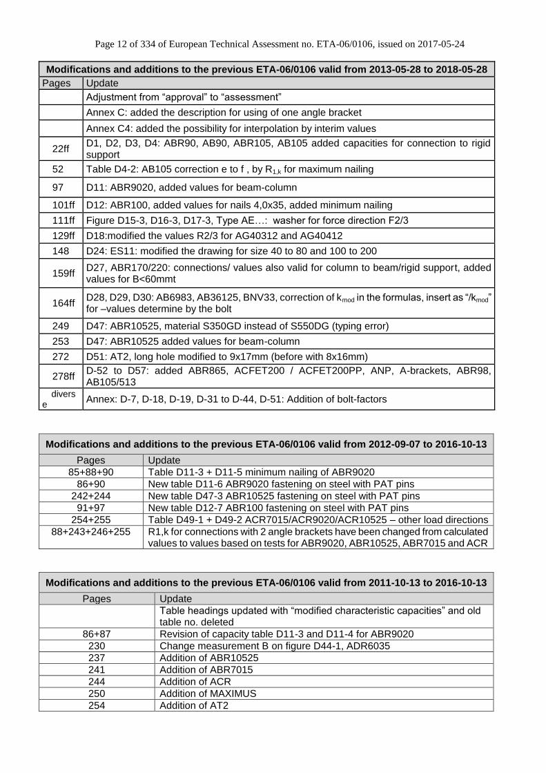
Modifications and additions to the previous ETA-06/0106 valid from 2013-05-28 to 2018-05-28
Pages Update
Adjustment from “approval” to “assessment”
Annex C: added the description for using of one angle bracket
Annex C4: added the possibility for interpolation by interim values
22ff D1, D2, D3, D4: ABR90, AB90, ABR105, AB105 added capacities for connection to rigid support
52 Table D4-2: AB105 correction e to f , by R1,k for maximum nailing
97 D11: ABR9020, added values for beam-column
101ff D12: ABR100, added values for nails 4,0x35, added minimum nailing
111ff Figure D15-3, D16-3, D17-3, Type AE…: washer for force direction F2/3
129ff D18:modified the values R2/3 for AG40312 and AG40412
148 D24: ES11: modified the drawing for size 40 to 80 and 100 to 200
159ff D27, ABR170/220: connections/ values also valid for column to beam/rigid support, added values for B<60mmt
164ff D28, D29, D30: AB6983, AB36125, BNV33, correction of kmod in the formulas, insert as “/kmod” for –values determine by the bolt
249 D47: ABR10525, material S350GD instead of S550DG (typing error)
253 D47: ABR10525 added values for beam-column
272 D51: AT2, long hole modified to 9x17mm (before with 8x16mm)
278ff D-52 to D57: added ABR865, ACFET200 / ACFET200PP, ANP, A-brackets, ABR98, AB105/513
diverse
Annex: D-7, D-18, D-19, D-31 to D-44, D-51: Addition of bolt-factors
Modifications and additions to the previous ETA-06/0106 valid from 2012-09-07 to 2016-10-13
Pages Update
85+88+90 Table D11-3 + D11-5 minimum nailing of ABR9020
86+90 New table D11-6 ABR9020 fastening on steel with PAT pins
242+244 New table D47-3 ABR10525 fastening on steel with PAT pins
91+97 New table D12-7 ABR100 fastening on steel with PAT pins
254+255 Table D49-1 + D49-2 ACR7015/ACR9020/ACR10525 – other load directions
88+243+246+255 R1,k for connections with 2 angle brackets have been changed from calculated values to values based on tests for ABR9020, ABR10525, ABR7015 and ACR
Modifications and additions to the previous ETA-06/0106 valid from 2011-10-13 to 2016-10-13
Pages Update
Table headings updated with “modified characteristic capacities” and old table no. deleted
86+87 Revision of capacity table D11-3 and D11-4 for ABR9020
230 Change measurement B on figure D44-1, ADR6035
237 Addition of ABR10525
241 Addition of ABR7015
244 Addition of ACR
250 Addition of MAXIMUS
254 Addition of AT2
Page 13 of 334 of European Technical Assessment no. ETA-06/0106, issued on 2017-05-24
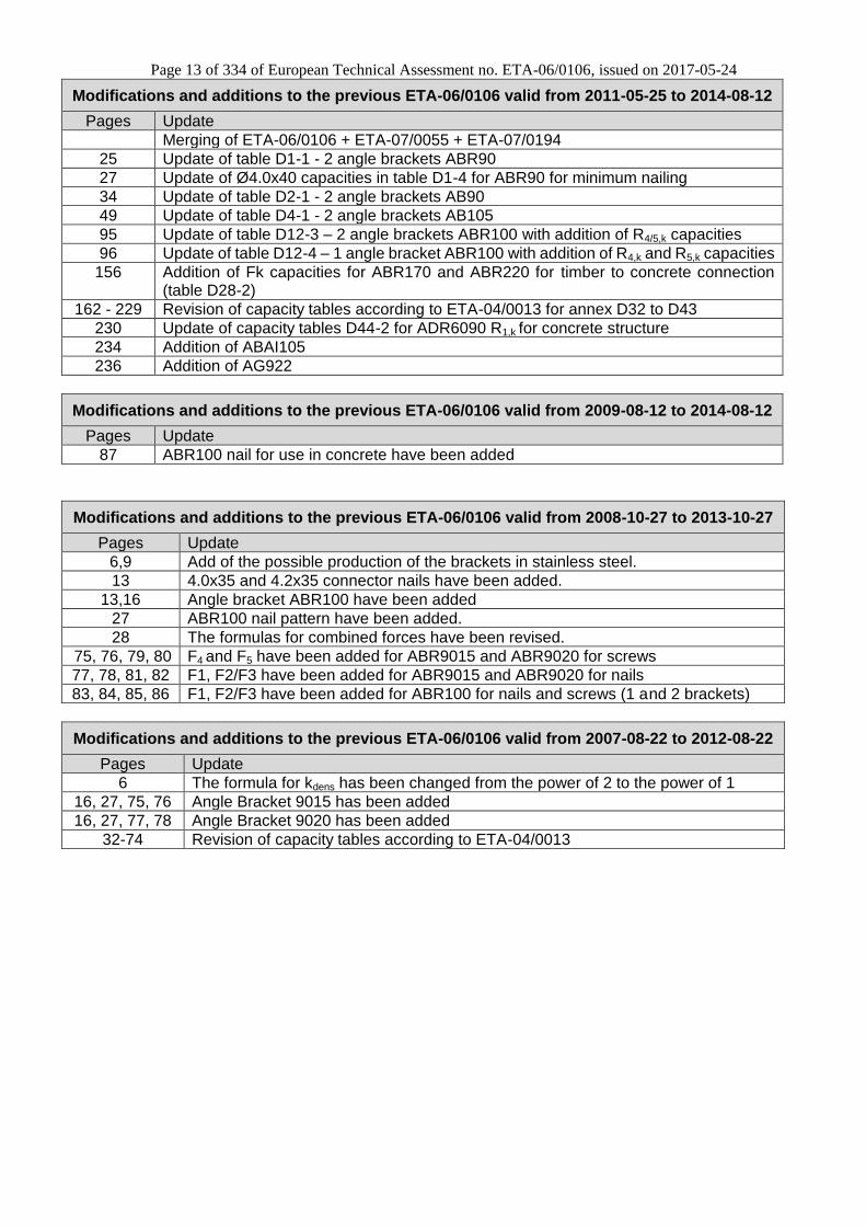
Modifications and additions to the previous ETA-06/0106 valid from 2011-05-25 to 2014-08-12
Pages Update
Merging of ETA-06/0106 + ETA-07/0055 + ETA-07/0194
25 Update of table D1-1 - 2 angle brackets ABR90
27 Update of Ø4.0x40 capacities in table D1-4 for ABR90 for minimum nailing
34 Update of table D2-1 - 2 angle brackets AB90
49 Update of table D4-1 - 2 angle brackets AB105
95 Update of table D12-3 – 2 angle brackets ABR100 with addition of R4/5,k capacities
96 Update of table D12-4 – 1 angle bracket ABR100 with addition of R4,k and R5,k capacities
156 Addition of Fk capacities for ABR170 and ABR220 for timber to concrete connection (table D28-2)
162 - 229 Revision of capacity tables according to ETA-04/0013 for annex D32 to D43
230 Update of capacity tables D44-2 for ADR6090 R1,k for concrete structure
234 Addition of ABAI105
236 Addition of AG922
Modifications and additions to the previous ETA-06/0106 valid from 2009-08-12 to 2014-08-12
Pages Update
87 ABR100 nail for use in concrete have been added
Modifications and additions to the previous ETA-06/0106 valid from 2008-10-27 to 2013-10-27
Pages Update
6,9 Add of the possible production of the brackets in stainless steel.
13 4.0x35 and 4.2x35 connector nails have been added.
13,16 Angle bracket ABR100 have been added
27 ABR100 nail pattern have been added.
28 The formulas for combined forces have been revised.
75, 76, 79, 80 F4 and F5 have been added for ABR9015 and ABR9020 for screws
77, 78, 81, 82 F1, F2/F3 have been added for ABR9015 and ABR9020 for nails
83, 84, 85, 86 F1, F2/F3 have been added for ABR100 for nails and screws (1 and 2 brackets)
Modifications and additions to the previous ETA-06/0106 valid from 2007-08-22 to 2012-08-22
Pages Update
6 The formula for kdens has been changed from the power of 2 to the power of 1
16, 27, 75, 76 Angle Bracket 9015 has been added
16, 27, 77, 78 Angle Bracket 9020 has been added
32-74 Revision of capacity tables according to ETA-04/0013
Page 14 of 334 of European Technical Assessment no. ETA-06/0106, issued on 2017-05-24
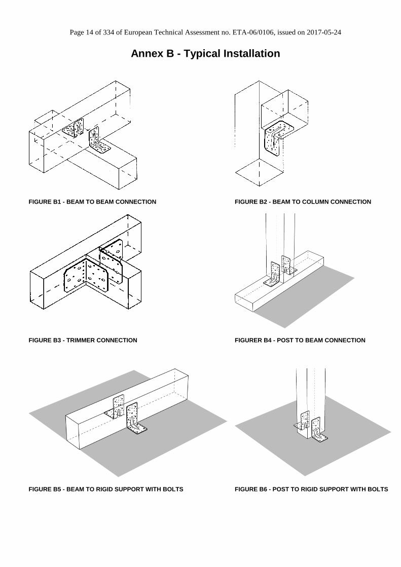
Annex B - Typical Installation
FIGURE B1 - BEAM TO BEAM CONNECTION FIGURE B2 - BEAM TO COLUMN CONNECTION
FIGURE B3 - TRIMMER CONNECTION FIGURER B4 - POST TO BEAM CONNECTION
FIGURE B5 - BEAM TO RIGID SUPPORT WITH BOLTS FIGURE B6 - POST TO RIGID SUPPORT WITH BOLTS

Page 15 of 334 of European Technical Assessment no. ETA-06/0106, issued on 2017-05-24
Typical installation of ACFET200 & ACFET200PP:
ACFET200 attached on a concrete wall ACFET200PP attached on a Lightweight Aggregate Concrete (LAC) wall
Typical installation of ABTR:
extra layer

Page 16 of 334 of European Technical Assessment no. ETA-06/0106, issued on 2017-05-24
Typical installation of ACW155:
- on front of concrete floor:
- on top of concrete floor:

Page 17 of 334 of European Technical Assessment no. ETA-06/0106, issued on 2017-05-24
Typical installation of AE90-RW:
Typical installation of ABR9015 fire shot on concrete:
Above are shown all the typical installation. Any other particular installation is described in the Annex D for the specific product.

Page 18 of 334 of European Technical Assessment no. ETA-06/0106, issued on 2017-05-24
Annex C - Basis of design
Annex C1 – Basis of Design
All the general basis of design are given here. These rules applied to all products listed in this ETA except if something else is stated in Annex D for a particular product.
Most of the capacities stated in the Annex D tables are modified characteristic capacities “Ri,k x kmod” It means that the capacity given for a specific load duration category (P, L, M, S or I) already takes into account the kmod factor. The design capacities are obtained according to the following formula.
M
k
d
kRR
"" mod
Some of the capacities stated in the Annex D tables are characteristic capacities Rk. Therefore, the design capacities are obtained according to the following formula:
M
k
d
kRR
mod
Combined forces For practical purposes, the strength verification is always carried out for design forces and design capacities. For all Angle Brackets included in this ETA, the following inequalities shall be fulfilled: F1 combined with F2 or F3:
1R
F
R
F2
,32
,322
,1
,1
dor
dor
d
d
F1 combined with F4 or F5:
1R
F
R
F
,54
,54
,1
,1
dor
dor
d
d
F1 combined with F2 or F3 and F4 or F5:
0,1
2
,32
,32
2
,54
,54
,1
,1
dor
dor
dor
dor
d
d
R
F
R
F
R
F
Timber splitting For forces acting perpendicular to the grain in the timber it must be checked that splitting will not occur in accordance with Eurocode 5 or a similar national Timber Code.
Page 19 of 334 of European Technical Assessment no. ETA-06/0106, issued on 2017-05-24
Annex C2 – Definition of forces direction
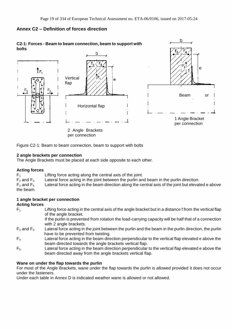
C2-1: Forces - Beam to beam connection, beam to support with
bolts
Figure C2-1: Beam to beam connection, beam to support with bolts
2 angle brackets per connection The Angle Brackets must be placed at each side opposite to each other.
Acting forces F1 Lifting force acting along the central axis of the joint. F2 and F3 Lateral force acting in the joint between the purlin and beam in the purlin direction. F4 and F5 Lateral force acting in the beam direction along the central axis of the joint but elevated e above the beam.
1 angle bracket per connection
Acting forces F1 Lifting force acting in the central axis of the angle bracket but in a distance f from the vertical flap
of the angle bracket. If the purlin is prevented from rotation the load-carrying capacity will be half that of a connection with 2 angle brackets.
F2 and F3 Lateral force acting in the joint between the purlin and the beam in the purlin direction, the purlin have to be prevented from twisting.
F4 Lateral force acting in the beam direction perpendicular to the vertical flap elevated e above the beam directed towards the angle brackets vertical flap.
F5 Lateral force acting in the beam direction perpendicular to the vertical flap elevated e above the beam directed away from the angle brackets vertical flap.
Wane on under the flap towards the purlin For most of the Angle Brackets, wane under the flap towards the purlin is allowed provided it does not occur under the fasteners. Under each table in Annex D is indicated weather wane is allowed or not allowed.
Purlin
Beam or support
1 Angle Bracket per connection
2 Angle Brackets per connection
Horizontal flap
Vertical flap
Page 20 of 334 of European Technical Assessment no. ETA-06/0106, issued on 2017-05-24
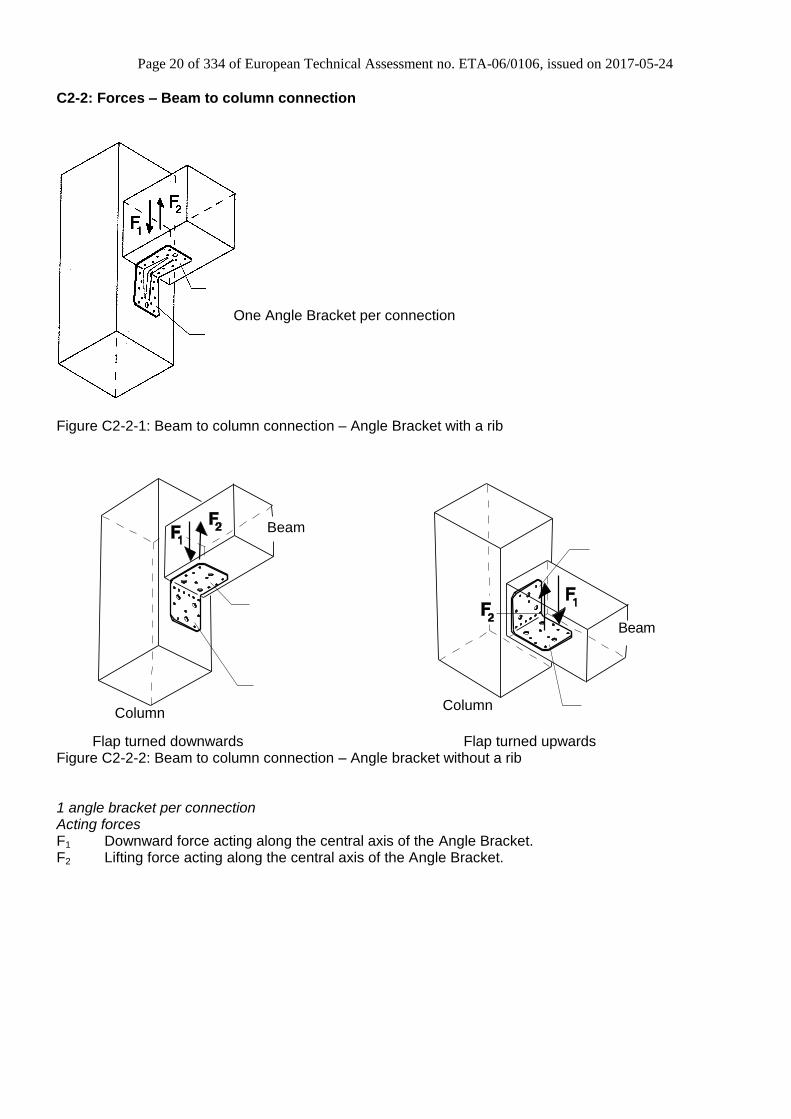
C2-2: Forces – Beam to column connection
Figure C2-2-1: Beam to column connection – Angle Bracket with a rib Flap turned downwards Flap turned upwards Figure C2-2-2: Beam to column connection – Angle bracket without a rib 1 angle bracket per connection Acting forces F1 Downward force acting along the central axis of the Angle Bracket. F2 Lifting force acting along the central axis of the Angle Bracket.
Beam
Column
Beam
Column
One Angle Bracket per connection
Page 21 of 334 of European Technical Assessment no. ETA-06/0106, issued on 2017-05-24
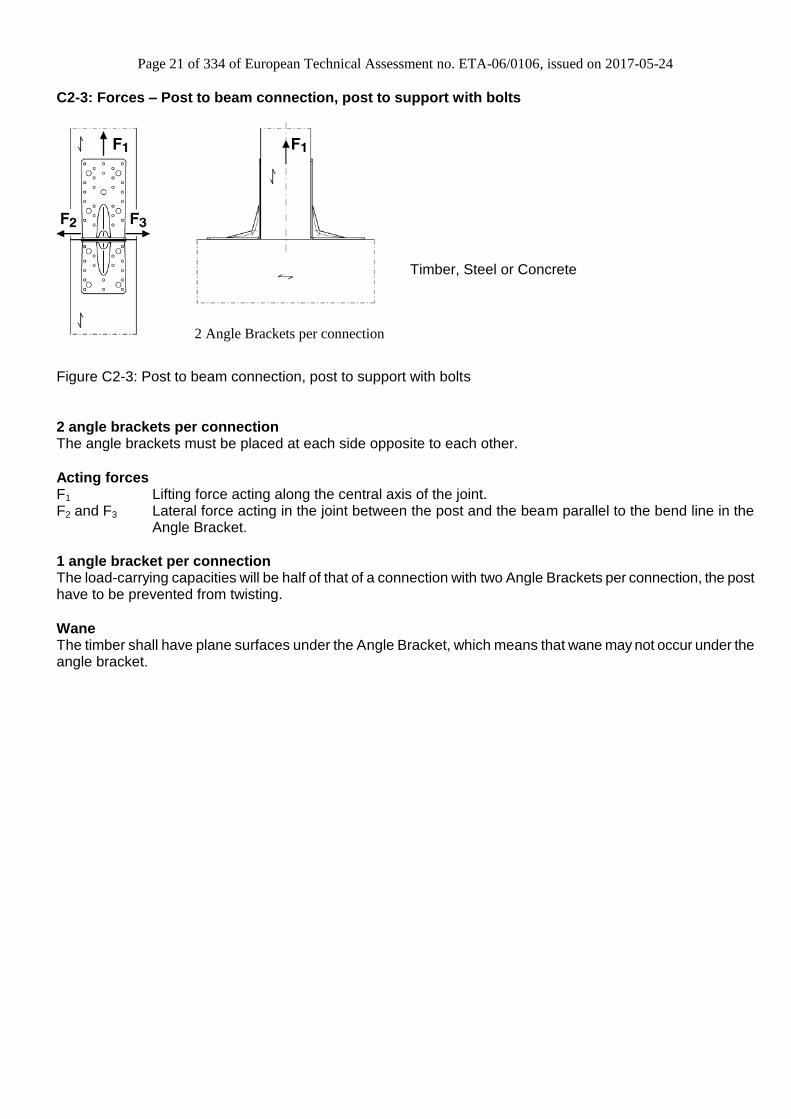
C2-3: Forces – Post to beam connection, post to support with bolts
Figure C2-3: Post to beam connection, post to support with bolts
2 angle brackets per connection The angle brackets must be placed at each side opposite to each other.
Acting forces F1 Lifting force acting along the central axis of the joint. F2 and F3 Lateral force acting in the joint between the post and the beam parallel to the bend line in the
Angle Bracket.
1 angle bracket per connection The load-carrying capacities will be half of that of a connection with two Angle Brackets per connection, the post have to be prevented from twisting.
Wane The timber shall have plane surfaces under the Angle Bracket, which means that wane may not occur under the angle bracket.
Purlin
2 Angle Brackets per connection
Timber, Steel or Concrete

Page 22 of 334 of European Technical Assessment no. ETA-06/0106, issued on 2017-05-24
C2-4: Forces – Trimmer connection
Figure B3: Trimmer connection
2 angle brackets per connection The angle brackets must be placed at each side opposite to each other.
Acting forces F2 and F3 Lateral force parallel to the bend line in the Angle Bracket in the joint between the joist and the header.
1 angle bracket per connection The load-carrying capacities will be half of that of a connection with 2 angle brackets per connection, the post has to be prevented from twisting.
Wane The timber shall have plane surfaces under the Angle Bracket, which means that wane may not occur under the angle bracket.
C2-5 : Connection with bolts Below the load-tables for connection with bolts are given factors. It has to be checked, that the bolt has a capacity to absorb the resultant overlapping forces. Rbolt ax/lat ≥ factor ax/lat x acting load. The factor klat is given to determine the shear load for the bolt The factor kax is given to determine the axial load for the bolt Each bolt shall have a capacity to sustain a lateral force of: ≥ k lat x Fi,d Each bolt shall have a capacity to sustain a axial force of: ≥ kax x Fi,d Combinations of loads have to be considered.
b
e
4/5F
e
1F
2/3F
F1 f
5F
4F
k x F lat i,d
k x F ax i,d
bolt 1
bolt 2

Page 23 of 334 of European Technical Assessment no. ETA-06/0106, issued on 2017-05-24
Annex C3 – Fasteners specification and capacities
CNA connector nails and CSA connector screws according to ETA-04/0013:
Other fasteners:
Nail and screw type Nail and screw
size (mm) Finish According to ETA-
04/0013 annex A drawing 1 and 2
Diameter Lengt
h
Connector nail 3,1 -- Electroplated zinc
Connector nail 3,7 50 Electroplated zinc
Connector nail 4,0 35 Electroplated zinc
Connector nail 4,0 40 Electroplated zinc
Connector nail 4,0 50 Electroplated zinc
Connector nail 4,0 60 Electroplated zinc
Connector screw 5,0 35 Electroplated zinc
Connector screw 5,0 40 Electroplated zinc
Connector screw 5,0 50 Electroplated zinc
Connector nail 4,2 35 Electroplated zinc
Connector nail 4,2 50 Electroplated zinc
Connector nail 4,2 60 Electroplated zinc
Nail, screw and bolt type
Nail, screw and bolt size (mm)
Finish Diameter
Length
Threaded nail according to EN 14592
3,1 -- Electroplated zinc
Smooth nail according to EN 14592
3,75 75 Hot-dip galvanized
Threaded nail according to EN 14592
4,0 -- Electroplated zinc
PDPA-75 4,0 19 Electroplated zinc
Wood screw 6,0 45 Electroplated zinc Wood screw 8,0 120 Electroplated zinc
Wood screw SD25600 6,4 152 Double-barrier coating
Bolt M8 8 For relevant angle brackets see the assumed characteristic capacities of the bolt connection and compare with the specification of the manufacturer
Bolt M10 10
Bolt M12 12

Page 24 of 334 of European Technical Assessment no. ETA-06/0106, issued on 2017-05-24
Annex C4 – Characteristic capacity modification methods for nails and timber types
C4 – 1: Characteristic capacity modification method for different nails
CNA Connector nails and CSA Connector screws in accordance to ETA-04/0013 When the load bearing capacity of a bracket have been determined based on the use of Connector nails CNA 4,0x35, CNA4,0x40, CNA4,0x50 or CNA4,0x60 in accordance with ETA-04/0013 it is allowed to use longer 4,0 mm CNA Connector nails or Connector screws CSA5,0x35, CSA5,0x40, CSA 5,0x50 or Connector nails CNA4,2x35, CNA4,2x50, CNA4,2x60 in accordance with ETA-04/0013 with the same or better performance than the used 4,0 mm CNA Connector nails and still achieve the same load-bearing capacity of the connection. When the load bearing capacity of a bracket have been determined based on the use of Connector screws it is always allowed to use a longer screw and the capacities will still be valid. If shorter Connector screws are used and no calculations are made a reduction factor equal to the ratio between the withdrawal capacity of the short screw and the withdrawal capacity of the long screw is applicable for all loadbearing capacities of the connection. It is always allowed to interpolate between two sizes of nails or screws. For example the capacity of Connector nails CNA 4,0x50 in accordance with ETA-04/0013 can be calculated as the mean value of the capacity of the connection when Connector nails CNA4,0x40 and CNA4,0x60 are used: To calculate the capacity with CNA4.0x50, the value of the capacity with CNA4.0x40 must be multiply by a factor k and must be limited to the value with CNA4.0x60.
For F1 load direction on timber k = RaxCNA4.0x60 / RaxCNA4.0x40 For F1 load direction on rigid support k = RlatCNA4.0x60 / Rlat CNAx4.0x40 For F2 and F3 load direction on all support k = RlatCNA4.0x60 / RlatCNAx40 For F4 and F5 load direction on all support k = RaxCNA4.0x60 / RaxCNA4.0x40
Threaded nails in accordance to EN 14592 For all Angle Brackets the design models also allow the use of threaded nails in accordance to EN 14592 with a diameter in the range 4,0 – 4,2 mm and a minimum length of 35 mm, assuming a thick steel plate when calculating the lateral nail load-bearing capacity. If no calculations are made a reduction factor equal to the ratio between the characteristic withdrawal capacity of the actual used threaded nail and the characteristic withdrawal capacity of the corresponding Connector nail according to table B1 in ETA-04/0013 is applicable for all load bearing capacities of the connection.
Other fasteners For some Angle Brackets, the load bearing capacities have been determined for a connection between a timber member and its support to a 6 mm steel member using PDPA-75 nails, which are powder actuated pins. The pins have been fastened through the existing holes in the Angle Brackets. Some Angle Brackets gives the loadbearing capacity for a connection between a timber member and a 6 mm steel quality S355. For this connection, there is no proportionality for other steel grades or thicknesses.
Stainless steel For the Angle Brackets produced from stainless steel number 1.4401, 1.4404, 1.4521 (Steel ref. 2) and 1.4301, 1.4509 (Steel ref. 3) according to EN 10088-2:2005 or a stainless steel with a minimum characteristic 0.2% yield stress of 240 MPa, a minimum 1.0% yield stress of 270 MPa and a minimum ultimate tensile strength of 530 MPa., the characteristic load carrying capacities can be considered as the same as those published in this document subject to the use of stainless CNA connector nails or CSA connector screws covered by the ETA-04/0013 or stainless threaded nails or screws in accordance to the standard EN 14592 respecting the rules given in the paragraph above for nails and screws according to ETA-04/0013 and EN14592.

Page 25 of 334 of European Technical Assessment no. ETA-06/0106, issued on 2017-05-24
C4 – 2: Characteristic capacity modification method for different timber types Annex D states the load-carrying capacities of the Angle Bracket connections for a characteristic density of 350 kg/m3. For timber or wood-based material with a lower characteristic density than 350 kg/m3 the load-carrying capacities shall be reduced by the kdens factor:
350
k
densk
Where ρk is the characteristic density of the timber in kg/m3.
For interim value, e.g. distances, it´s allowed to determine the values by interpolation if nothing else is named by the current table.

Page 26 of 334 of European Technical Assessment no. ETA-06/0106, issued on 2017-05-24
Annex D - Product definition and capacities

Page 27 of 334 of European Technical Assessment no. ETA-06/0106, issued on 2017-05-24
Annex D1 – ABR90
Product Name:
Product
Name
Material reference
acc. to clause II-1 Alternative product names
ABR90 Steel ref. 1 UK: E2/2.5/7090, France: E2/2.5/7090, Germany: 90 m/R
ABR90S Steel ref. 2 France: E2IX
ABR90S2 Steel ref. 3 -
Connector Size Range:
Model no. Dimensions [mm] Holes flange A Holes flange B
A B C Thickness Ø5 Ø11 Ø5 Ø11
ABR90 90 90 65 2,5 10 1 10 1
Drawing:
Nailing pattern:
Nailing pattern 1 Nailing pattern 2 Nailing pattern 3 Nailing pattern 4 Nailing pattern 5
Flange A:
Flange B:
Beam to beam
Maximum nailing Beam to beam
Minimum nailing
Beam (A) to steel (B)
Maximum nailing
Beam (A) to steel (B)
Minimum nailing
Beam (A) to column (B)
Page 28 of 334 of European Technical Assessment no. ETA-06/0106, issued on 2017-05-24
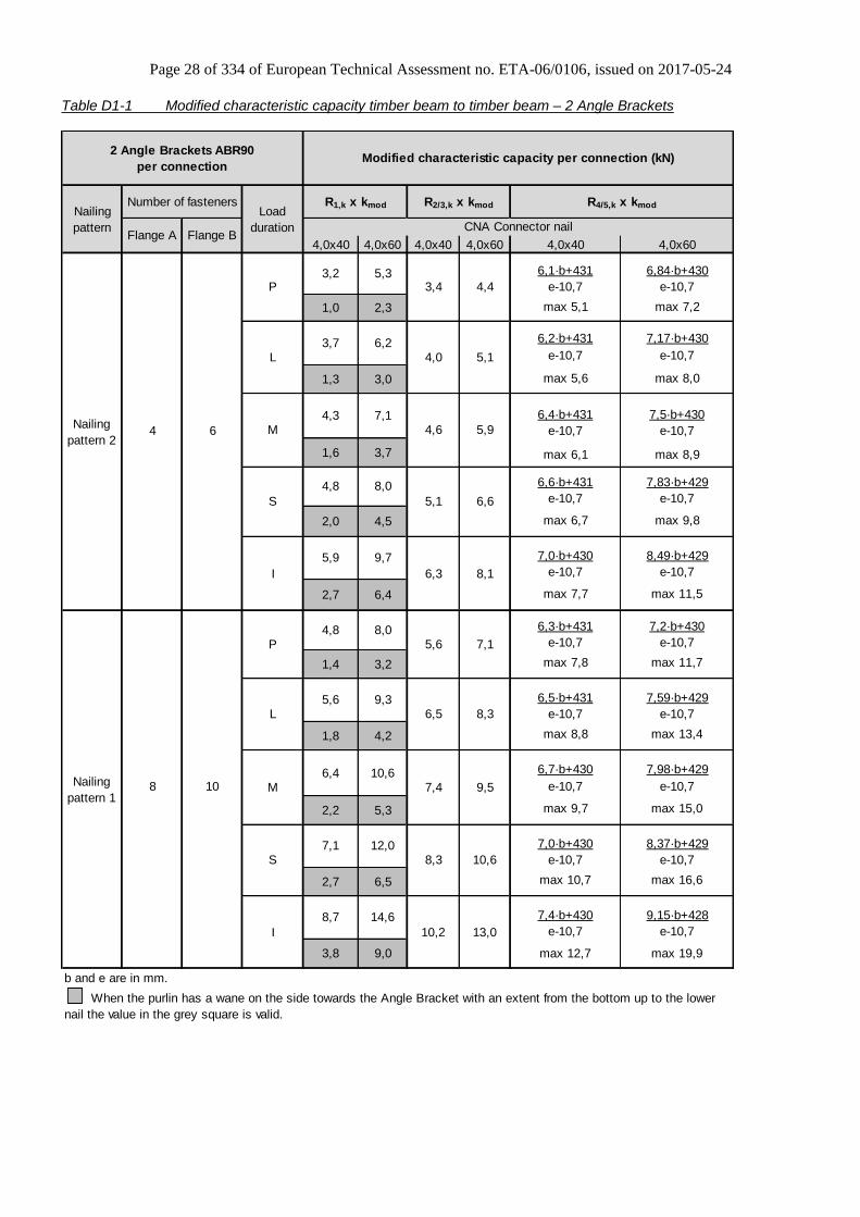
Table D1-1 Modified characteristic capacity timber beam to timber beam – 2 Angle Brackets
4,0x40 4,0x60 4,0x40 4,0x60 4,0x40 4,0x60
6,1·b+431 6,84·b+430
e-10,7 e-10,7
max 5,1 max 7,2
6,2·b+431 7,17·b+430
e-10,7 e-10,7
max 5,6 max 8,0
6,4·b+431 7,5·b+430
4 6 e-10,7 e-10,7
max 6,1 max 8,9
6,6·b+431 7,83·b+429
e-10,7 e-10,7
max 6,7 max 9,8
7,0·b+430 8,49·b+429
e-10,7 e-10,7
max 7,7 max 11,5
6,3·b+431 7,2·b+430
e-10,7 e-10,7
max 7,8 max 11,7
6,5·b+431 7,59·b+429
e-10,7 e-10,7
max 8,8 max 13,4
6,7·b+430 7,98·b+429
8 10 e-10,7 e-10,7
max 9,7 max 15,0
7,0·b+430 8,37·b+429
e-10,7 e-10,7
max 10,7 max 16,6
7,4·b+430 9,15·b+428
e-10,7 e-10,7
max 12,7 max 19,9
b and e are in mm.
Number of fasteners
Flange A Flange B
8,7 14,6
10,2 13,0
3,8 9,0
7,1 12,08,3 10,6
2,7 6,5
4,2
6,4 10,67,4 9,5
2,2 5,3
8,05,6 7,1
1,4 3,2
5,6 9,36,5 8,3
1,8
6,3 8,1
6,6
Nailing
pattern 1
P
L
M
S
I
4,8
4,3 7,1
5,9 9,7
2,7 6,4
5,1
4,8 8,0
4,6 5,9
5,1
2,0 4,5
1,6 3,7
5,3
2,3
6,24,0
3,4
1,3 3,0
R4/5,k x kmod
CNA Connector nail
P
L
M
S
4,4
3,7
3,2
1,0
2 Angle Brackets ABR90
per connectionModified characteristic capacity per connection (kN)
When the purlin has a wane on the side towards the Angle Bracket with an extent from the bottom up to the lower
nail the value in the grey square is valid.
I
Nailing
pattern 2
Nailing
pattern
Load
duration
R1,k x kmod R2/3,k x kmod

Page 29 of 334 of European Technical Assessment no. ETA-06/0106, issued on 2017-05-24
Table D1-2 Modified characteristic capacity timber beam to timber beam – 1 Angle Bracket Load duration P
4,0x40 4,0x60 4,0x40 4,0x60 4,0x40 4,0x60 4,0x40 4,0x60
e<37,5: e<37,5: e≤ 58: e≤ 55:
30,6 50,9 31 52
f≤ 40: f≤ 49: 37,5-e 37,5-e 68-e 68-e
78 114 58<e≤ 1,83·b: 55<e≤ 1,62·b+3:
f+60 f+60 e≤ 37: 2,2 e≤ 42: 2,83
37<e≤ 101: 42<e≤ 109:
81 119,8
e e
f>40: f>49:
e>1,83·b: e>1,62·b+3:
31,1 51,7
f f e>101: e>109: 6,1·b-225 6,84·b-271
28,9 48 e-68 e-68
e-65 e-65
e<37,5: e<37,5: e≤ 57: e≤ 54:
37,5 62,7 46,3 77,5
f≤ 34: f≤ 41: 37,5-e 37,5-e 68-e 68-e
85 127 57<e≤ 1,47·b+10: 54<e≤ 1,23·b+15:
f+60 f+60 e≤ 20: 4,4 e≤ 23: 5,66
20<e≤ 96: 23<e≤ 102:
89 133,1
e e
f>34: f>41: e>1,47·b+10: e>1,23·b+15:
30,9 51,7 6,3·b-247 7,2·b-308
f f e>96: e>102: e-68 e-68
28,7 48
e-65 e-65
b, e and f are in mm.
Flange B
4 6
8 10
P
P
When the purlin has a wane on the side towards the Angle Bracket with an extent from the bottom up to the lower nail the formula in the grey
square shall be checked additionelly.
Modified characteristic capacity per connection (kN)
Load
duration
Nailing
pattern 2
1 Angle Bracket ABR90
per connection
Nailing
pattern CNA Connector nail
R1,k x kmodNumber of fasteners
Flange A
2,8 3,5
4,3 5,8
1,7
Nailing
pattern 1
2,2
R2/3,k x kmod R4,k x kmod R5,k x kmod
3,3 4,2
Page 30 of 334 of European Technical Assessment no. ETA-06/0106, issued on 2017-05-24
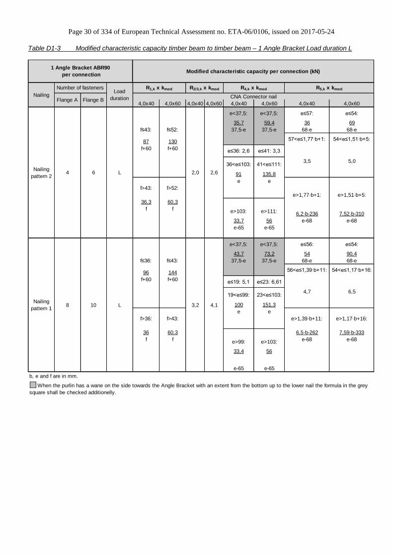
Table D1-3 Modified characteristic capacity timber beam to timber beam – 1 Angle Bracket Load duration L
4,0x40 4,0x60 4,0x40 4,0x60 4,0x40 4,0x60 4,0x40 4,0x60
e<37,5: e<37,5: e≤57: e≤54:
35,7 59,4 36 69
f≤43: f≤52: 37,5-e 37,5-e 68-e 68-e
87 130 57<e≤1,77·b+1: 54<e≤1,51·b+5:
f+60 f+60 e≤36: 2,6 e≤41: 3,3
36<e≤103: 41<e≤111:
91 135,8
e e
f>43: f>52:
e>1,77·b+1: e>1,51·b+5:
36,3 60,3
f f e>103: e>111: 6,2·b-236 7,52·b-310
33,7 56 e-68 e-68
e-65 e-65
e<37,5: e<37,5: e≤56: e≤54:
43,7 73,2 54 90,4
f≤36: f≤43: 37,5-e 37,5-e 68-e 68-e
96 144 56<e≤1,39·b+11: 54<e≤1,17·b+16:
f+60 f+60 e≤19: 5,1 e≤23: 6,61
19<e≤99: 23<e≤103:
100 151,3
e e
f>36: f>43: e>1,39·b+11: e>1,17·b+16:
36 60,3 6,5·b-262 7,59·b-333
f f e>99: e>103: e-68 e-68
33,4 56
e-65 e-65
b, e and f are in mm.
L8 10
4,7 6,5
3,5 5,0
Number of fasteners
Flange A Flange B
4 6 L
R1,k x kmod R2/3,k x kmod R4,k x kmod
2,0 2,6
3,2 4,1Nailing
pattern 1
When the purlin has a wane on the side towards the Angle Bracket with an extent from the bottom up to the lower nail the formula in the grey
square shall be checked additionelly.
1 Angle Bracket ABR90
per connectionModified characteristic capacity per connection (kN)
NailingLoad
duration
Nailing
pattern 2
CNA Connector nail
R5,k x kmod

Page 31 of 334 of European Technical Assessment no. ETA-06/0106, issued on 2017-05-24
Table D1-4 Modified characteristic capacity timber beam to timber beam – 1 Angle Bracket Load duration M
4,0x40 4,0x60 4,0x40 4,0x60 4,0x40 4,0x60 4,0x40 4,0x60
e<37,5: e<37,5: e≤56: e≤54:
40,8 67,9 41 69
f≤45: f≤55: 37,5-e 37,5-e 68-e 68-e
96 145 56<e≤1,71·b+2: 54<e≤1,51·b+5:
f+60 f+60 e≤34: 2,9 e≤40: 3,78
34<e≤105: 40<e≤112:
101 151,9
e e
f>45: f>55:
e>1,71·b+2: e>1,51·b+5:
41,4 68,9
f f e>105: e>112: 6,4·b-248 7,5·b-309
38,5 64 e-68 e-68
e-65 e-65
e<37,5: e<37,5: e≤55: e≤53:
50 83,6 62 103
f≤38: f≤45: 37,5-e 37,5-e 68-e 68-e
106 161 e≤19: 5,9 e≤22: 7,55 55<e≤1,33·b+13: 53<e≤1,12·b+17:
f+60 f+60 22<e≤92:
169,6
19<e≤99: e
111
e 92<e≤111:
f>38: f>45: 109,5 e>1,33·b+13: e>1,12·b+17:
e-32,5
41,2 68,9 e>99: 6,7·b-277 7,98·b-359
f f38,2 e>111: e-68 e-68
e-65 64
e-65
b, e and f are in mm.
8 10
M
M
2,9
Number of fasteners
Flange A Flange B
4 6
R2/3,k x kmod R4,k x kmod R5,k x kmod
3,8 5,0
3,7 4,7
5,0 7,1
2,3
Nailing
pattern 1
When the purlin has a wane on the side towards the Angle Bracket with an extent from the bottom up to the lower nail the formula in the grey
square shall be checked additionelly.
1 Angle Bracket ABR90
per connectionModified characteristic capacity per connection (kN)
Nailing
pattern
Load
duration
Nailing
pattern 2
CNA Connector nail
R1,k x kmod
Page 32 of 334 of European Technical Assessment no. ETA-06/0106, issued on 2017-05-24
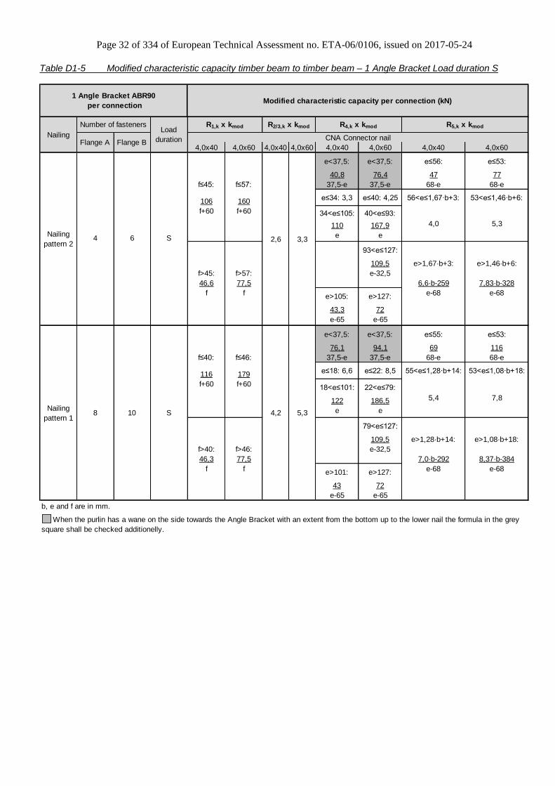
Table D1-5 Modified characteristic capacity timber beam to timber beam – 1 Angle Bracket Load duration S
4,0x40 4,0x60 4,0x40 4,0x60 4,0x40 4,0x60 4,0x40 4,0x60
e<37,5: e<37,5: e≤56: e≤53:
40,8 76,4 47 77
f≤45: f≤57: 37,5-e 37,5-e 68-e 68-e
106 160 e≤34: 3,3 e≤40: 4,25 56<e≤1,67·b+3: 53<e≤1,46·b+6:
f+60 f+60 34<e≤105: 40<e≤93:
110 167,9
e e
93<e≤127:
109,5 e>1,67·b+3: e>1,46·b+6:
f>45: f>57: e-32,5
46,6 77,5 6,6·b-259 7,83·b-328
f f e>105: e>127: e-68 e-68
43,3 72
e-65 e-65
e<37,5: e<37,5: e≤55: e≤53:
76,1 94,1 69 116
f≤40: f≤46: 37,5-e 37,5-e 68-e 68-e
116 179 e≤18: 6,6 e≤22: 8,5 55<e≤1,28·b+14: 53<e≤1,08·b+18:
f+60 f+60 18<e≤101: 22<e≤79:
122 186,5
e e
79<e≤127:
109,5 e>1,28·b+14: e>1,08·b+18:
f>40: f>46: e-32,5
46,3 77,5 7,0·b-292 8,37·b-384
f f e>101: e>127: e-68 e-68
43 72
e-65 e-65
b, e and f are in mm.
8 10
S
S
5,3
Number of fasteners
Flange A Flange B
4 6
R4,k x kmod R5,k x kmod
4,2 5,3
5,4 7,8
2,6 3,3
CNA Connector nail
4,0
Nailing
pattern 1
Nailing
pattern 2
When the purlin has a wane on the side towards the Angle Bracket with an extent from the bottom up to the lower nail the formula in the grey
square shall be checked additionelly.
1 Angle Bracket ABR90
per connectionModified characteristic capacity per connection (kN)
NailingLoad
duration
R1,k x kmod R2/3,k x kmod

Page 33 of 334 of European Technical Assessment no. ETA-06/0106, issued on 2017-05-24
Table D1-6 Modified characteristic capacity timber beam to timber beam – 1 Angle Bracket Load duration I
4,0x40 4,0x60 4,0x40 4,0x60 4,0x40 4,0x60 4,0x40 4,0x60
e<37,5: e<37,5: e≤55: e≤52:
56,2 93,4 57 95
f≤51: f≤60: 37,5-e 37,5-e 68-e 68-e
124 190 e≤32: 4,0 e≤36: 5,19 55<e≤1,58·b+4: 52<e≤1,39·b+7:
f+60 f+60 32<e≤95: 36<e≤79:
130 186,5
e e
95<e≤110: 79<e≤198:
109 109,5 e>1,58·b+4: e>1,39·b+7:
f>51: f>60: e-32,5 e-32,5
57 94,7 7,0·b-282 8,49·b-366
f f e>110: e>198: e-68 e-68
52,9 87,9
e-65 e-65
e<37,5: e<37,5: e≤54: e≤52:
68,7 115 85 142
f≤42: f≤48: 37,5-e 37,5-e 68-e 68-e
137 213 e≤18: 8,1 e≤18: 10,38 54<e≤1,20·b+16: 52<e≤1,01·b+20:
f+60 f+60 18<e≤103: 18<e≤79:
144 186,5
e e
79<e≤200:
e>103: 109,5 e>1,20·b+16: e>1,01·b+20:
f>42: f>48: e-32,5
56,6 94,7 52,6 7,4·b-322 9,15·b-435
f f e-65 e>200: e-68 e-68
87,9
e-65
b, e and f are in mm.
8 10
I
I
4,0
Number of fasteners
Flange A Flange B
4 6
R2/3,k x kmod R4,k x kmod R5,k x kmod
4,4 6,1
5,1 6,5
6,2 9,1
3,1
When the purlin has a wane on the side towards the Angle Bracket with an extent from the bottom up to the lower nail the formula in the grey
square shall be checked additionelly.
1 Angle Bracket ABR90
per connectionModified characteristic capacity per connection (kN)
Nailing
pattern
Load
duration
Nailing
pattern 1
Nailing
pattern 2
CNA Connector nail
R1,k x kmod

Page 34 of 334 of European Technical Assessment no. ETA-06/0106, issued on 2017-05-24
Table D1-7 Modified characteristic capacity timber beam to timber column – 1 Angle Bracket
Flange A
(beam)
Flange B
(column)
P 5,4 6,6 0,9 1,5
L 6,3 7,7 1,0 1,7
M 7,2 8,8 1,2 2,0
S 8,1 9,9 1,3 2,2
I 9,9 12,1 1,6 2,7
End gab: max. 5 mm
CN
A4,0
x40
CN
A4,0
x60
CN
A4,0
x40
CN
A4,0
x60
R2,k x kmod
Modified characteristic capacities
(kN) - timber to timber
R1,k x kmod
Nailing pattern 5
Number of fasteners
4 10
1 Angle Bracket ABR90 per connection
Nailing patternLoad
duration
Table D1-8 Characteristic capacity timber beam to rigid support – 2 Angle Brackets
Flange A Flange B 4,0x35 4,0x40 4,0x50 4,0x60 4,0x35 4,0x40 4,0x50 4,0x60
3,1 3,7 4,94 6,14 1,64 1,96 2,6 3,2
0,74 0,9 1,2 1,48 0,13 0,16 0,22 0,271) see table D1-9
4,0x35 to 4,0x60
Characteristic capacities per connection (kN)
CNA connector nails
2 Angle Brackets ABR90 per
connection
Nailing
pattern
Number of fasteners
8 1 Bolt
4 1 Bolt
R4/5,k
Nailing
pattern 3
min of:
3,2/kmod
Nailing
pattern 4
R1,k R2/3,k
e
bR
k
RR
2;
17,2min
max1
mod
)1
5
)1
4
Connection with bolt
factor for: F1 F2/3 F4/5,bolt1 F4/5,bolt2
kax 0,50 - 0,50 0,10
klat - 0,5 - 1,00
For each bolt it's needed to check: Rbolt,d,lateral ≥ klat x Fi,d ; Rbolt,d,axial ≥ kax x Fi,d; and also the combination.
2 Angle Bracket ABR90 per connection
F1
F2fF
4
e5
F
e
F4/5
b bolt 2bolt 1

Page 35 of 334 of European Technical Assessment no. ETA-06/0106, issued on 2017-05-24
Table D1-9 Characteristic capacity timber beam to rigid support – 1 Angle Bracket
Flange A Flange B 4,0x35 4,0x40 4,0x50 4,0x60
222 266 355 443
107 128 171 213
e is to insert in [mm]; e≥ 10mm
negativ values shall not be considered
Nailing
pattern
Number of fasteners
Nailing
pattern 38 1 Bolt
4,0x35 to 4,0x60
CNA connector nails
Nailing
pattern 44 1 Bolt
21,7 / ((f+16) x kmod) 21,7 / (e x kmod)
Half of the values for a connection with 2
ABR90, if the timber is prevented from
rotation, otherwise R_2/3=0,0kN
Characteristic capacities per connection (kN)
4,0x35 to 4,0x60
R1,k R4,k
4,0x35 to 4,0x60
R2/3,k R5,k
X1=
X2=
1 Angle Bracket ABR90 per
connection
mod
110;
85
2;
99,9
1min
keemm
X
mme
X
Connection with bolt
factor for: F1 F2/3 F4 F5
kax 1,00 - e/20 e/95
klat - - 1,00 1,00
For each bolt it's needed to check: Rbolt,d,lateral ≥ klat x Fi,d ; Rbolt,d,axial ≥ kax x Fi,d; and also the combination.
1 Angle Bracket ABR90 per connection

Page 36 of 334 of European Technical Assessment no. ETA-06/0106, issued on 2017-05-24
Annex D2 – AB90
Product Name:
Product
Name
Material reference
acc. to clause II-1 Alternative product names
AB90 Steel ref. 1 France: E2/2.5/7091, Germany: 90 o/R
AB90S Steel ref. 2 -
AB90S2 Steel ref. 3 -
Connector Size Range:
Model no. Dimensions [mm] Holes flange A Holes flange B
A B C Thickness Ø5 Ø11 Ø5 Ø11
AB90 88 88 65 2,5 6 3 9 2
Drawing:
Nailing pattern:
Nailing pattern 1 Nailing pattern 2 Nailing pattern 3 Nailing pattern 4 Nailing pattern 5
Flange A:
Flange B:
Beam to beam
Maximum nailing Beam to beam
Minimum nailing Beam (A)
to column (B) Trimmer
connection Beam (B) to rigid support (A) Bolts
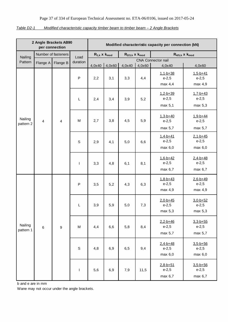
Page 37 of 334 of European Technical Assessment no. ETA-06/0106, issued on 2017-05-24
Table D2-1 Modified characteristic capacity timber beam to timber beam – 2 Angle Brackets
4,0x40 4,0x60 4,0x40 4,0x60 4,0x40 4,0x60
1,1·b+38 1,5·b+41
e-2,5 e-2,5
max 4,4 max 4,9
1,2·b+39 1,7·b+43
e-2,5 e-2,5
max 5,1 max 5,3
1,3·b+40 1,9·b+44
e-2,5 e-2,5
max 5,7 max 5,7
1,4·b+41 2,1·b+45
e-2,5 e-2,5
max 6,0 max 6,0
1,6·b+42 2,4·b+48
e-2,5 e-2,5
max 6,7 max 6,7
1,8·b+43 2,6·b+49
e-2,5 e-2,5
max 4,9 max 4,9
2,0·b+45 3,0·b+52
e-2,5 e-2,5
max 5,3 max 5,3
2,2·b+46 3,3·b+55
e-2,5 e-2,5
max 5,7 max 5,7
2,4·b+48 3,5·b+56
e-2,5 e-2,5
max 6,0 max 6,0
2,8·b+51 3,5·b+56
e-2,5 e-2,5
max 6,7 max 6,7
b and e are in mm
Wane may not occur under the angle brackets.
Number of fasteners
Flange A Flange B
4 4
6 9
4,8 6,9
5,6 6,9
3,3 4,8
4,4
3,4
4,4
3,9
3,3
5,2
2,9 4,1
Nailing
pattern 2
Nailing
Pattern
Load
duration
R1,k x kmod R2/3,k x kmod R4/5,k x kmod
CNA Connector nail
2,2 3,1
2,4
5,9
5,0 6,6
M
S
I
I
6,1 8,1
2,7 3,8
4,3 6,33,5 5,2
4,5
7,9 11,5
6,5 9,4
5,8Nailing
pattern 1
P
L
M
S
8,4
2 Angle Brackets AB90
per connectionModified characteristic capacity per connection (kN)
5,0 7,33,9 5,9
6,6
P
L
Page 38 of 334 of European Technical Assessment no. ETA-06/0106, issued on 2017-05-24
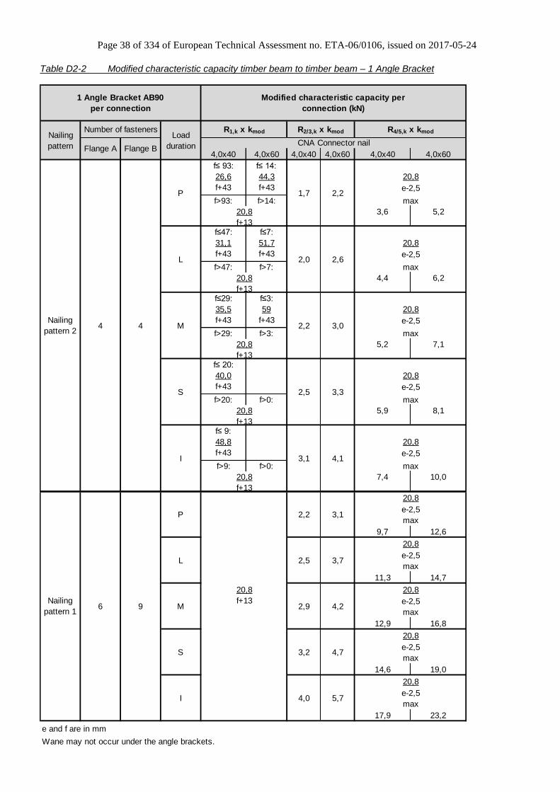
Table D2-2 Modified characteristic capacity timber beam to timber beam – 1 Angle Bracket
4,0x40 4,0x60 4,0x40 4,0x60 4,0x40 4,0x60
f≤ 93: f≤ 14:
26,6 44,3
f+43 f+43
f>93: f>14:
3,6 5,2
f≤47: f≤7:
31,1 51,7
f+43 f+43
f>47: f>7:
4,4 6,2
f≤29: f≤3:
35,5 59
f+43 f+43
f>29: f>3:
5,2 7,1
f≤ 20:
40,0
f+43
f>20: f>0:
5,9 8,1
f≤ 9:
48,8
f+43
f>9: f>0:
7,4 10,0
9,7 12,6
11,3 14,7
12,9 16,8
14,6 19,0
17,9 23,2
e and f are in mm
Wane may not occur under the angle brackets.
Number of fasteners
Flange A Flange B
4 4
6 9
20,8
e-2,5
maxI 4,0 5,7
Nailing
pattern 1
S
M
L
P
20,8
e-2,5
max3,2 4,7
e-2,5
max2,9 4,2
f+13
20,8
e-2,5
20,8
f+13
4,1
20,8
e-2,5
P
L
M
I
2,2
2,0
20,8
1,7
f+13
20,8
max
Nailing
pattern
Load
duration
R1,k x kmod R2/3,k x kmod R4/5,k x kmod
3,3
20,8
Nailing
pattern 2
3,1
e-2,5S 2,5
max
20,8
f+13
max2,5 3,7
20,8
20,8
e-2,52,2 3,1
max
20,8
max
2,6
20,8
e-2,5
max
3,0
20,8
e-2,5
1 Angle Bracket AB90
per connection
Modified characteristic capacity per
connection (kN)
2,2
f+13
f+13
CNA Connector nail
20,8
max
20,8
e-2,5

Page 39 of 334 of European Technical Assessment no. ETA-06/0106, issued on 2017-05-24
Table D2-3 Modified characteristic capacity timber beam to timber column – 1 Angle Bracket
R2,k x kmod
Flap turned
downwards
Flap turned
upwards
P 3,8 3,4
L 4,5 3,6
M 4,7 3,8
S 4,9 3,9
I 5,3 4,2
End gab: max. 5 mm
4 4Nailing
pattern 3
R1,k x kmod
Modified characteristic capacity per connection (kN)
0,7
CNA 4,0x40 / CNA 4,0x60
Number of fasteners
1 Angle Bracket AB90 per connection
Nailing
pattern Flange A
(beam)
Flange B
(column)
Load
duration
Table D2-4 Modified characteristic capacity trimmer connection – 2 Angle Brackets
Joist
flange (A)
Header
flange (B)
P 4,3 6,2
L 5,0 7,2
M 5,8 8,2
S 6,5 9,2
I 7,9 11,5
Wane may not occur under the angle brackets.
2 Angle Brackets AB90
per connection
6 9Nailing
pattern 4
Modified characteristic
capacities (kN)
R2,3k x kmod
CNA4,0x40 CNA4,0x60Nailing pattern
Number of fasteners
Load
duration
Page 40 of 334 of European Technical Assessment no. ETA-06/0106, issued on 2017-05-24
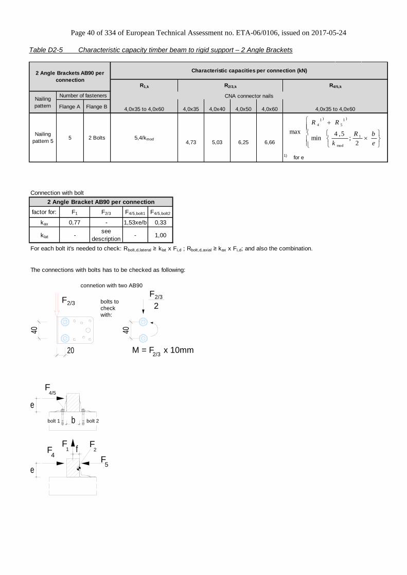
Table D2-5 Characteristic capacity timber beam to rigid support – 2 Angle Brackets
Flange A Flange B 4,0x35 4,0x40 4,0x50 4,0x60
4,73 5,03 6,25 6,66
1) for e
R4/5,k
Characteristic capacities per connection (kN)
CNA connector nails
2 Angle Brackets AB90 per
connection
Nailing
pattern
Number of fasteners
5 2 Bolts
R1,k R2/3,k
4,0x35 to 4,0x60
Nailing
pattern 55,4/kmod
4,0x35 to 4,0x60
e
bR
k
RR
2;
5,4min
max1
mod
)1
5
)1
4
Connection with bolt
factor for: F1 F2/3 F4/5,bolt1 F4/5,bolt2
kax 0,77 - 1,53xe/b 0,33
klat -see
description- 1,00
For each bolt it's needed to check: Rbolt,d,lateral ≥ klat x Fi,d ; Rbolt,d,axial ≥ kax x Fi,d; and also the combination.
The connections with bolts has to be checked as following:
2 Angle Bracket AB90 per connection
20
40
2/3F 2/3F
M = F x 10mm
2/3
2
40
connetion with two AB90
bolts to check with:
20
40
2/3F 2/3F
M = F x 10mm2/3
2
40
connetion with two AB90
bolts to
check
with:
F1
F2fF
4
e5
F
e
F4/5
b bolt 2bolt 1

Page 41 of 334 of European Technical Assessment no. ETA-06/0106, issued on 2017-05-24
Table D2-6 Characteristic capacity timber beam to rigid support – 1 Angle Bracket
Flange A Flange B 4,0x35 4,0x40 4,0x50 4,0x60
123 148 197 246
63 75 100 125
e is to insert in [mm]; e≥ 10mm
negativ values shall not be considered
1 Angle Bracket AB90 per
connection
Characteristic capacities per connection (kN)
R1,k R4,k R2/3,k R5,k
Nailing
pattern
Number of fasteners
4,0x35 to 4,0x60 4,0x35 to 4,0x60
CNA connector nails
4,0x35 to 4,0x60
19,9 / ((f +16) x kmod) 45,2 / (e x kmod)
Half of the values for a connection with 2
AB90, if the timber is prevented from
rotation, otherwise R_2/3=0,0kN
X1=
X2=Nailing
pattern 55 2 bolts
mod
110;
85
2;
99,9
1min
keemm
X
mme
X
Connection with bolt
factor for: F1 F2/3 F4 F5
kax 1,53 - e/30 e/26
klat -see
description1,00 1,00
For each bolt it's needed to check: Rbolt,d,lateral ≥ klat x Fi,d ; Rbolt,d,axial ≥ kax x Fi,d; and also the combination.
1 Angle Bracket AB90 per connection
2/3F
2/3F
M = F x (f+20mm)2/320
40 40
f
connetion with one AB90
bolts to check with:
Page 42 of 334 of European Technical Assessment no. ETA-06/0106, issued on 2017-05-24
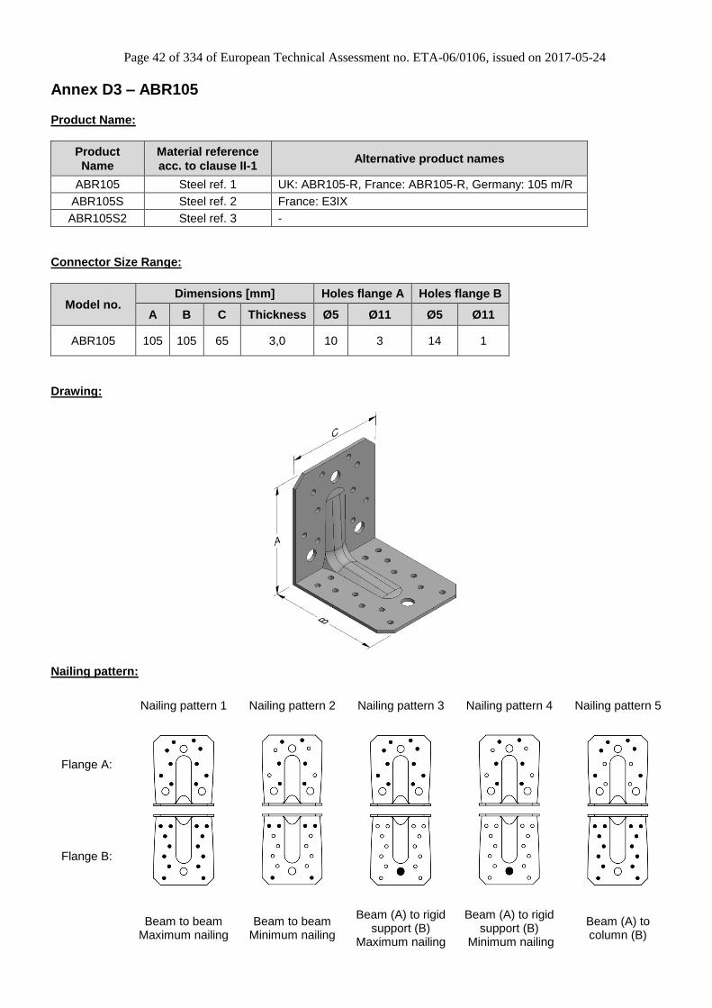
Annex D3 – ABR105
Product Name:
Product
Name
Material reference
acc. to clause II-1 Alternative product names
ABR105 Steel ref. 1 UK: ABR105-R, France: ABR105-R, Germany: 105 m/R
ABR105S Steel ref. 2 France: E3IX
ABR105S2 Steel ref. 3 -
Connector Size Range:
Model no. Dimensions [mm] Holes flange A Holes flange B
A B C Thickness Ø5 Ø11 Ø5 Ø11
ABR105 105 105 65 3,0 10 3 14 1
Drawing:
Nailing pattern:
Nailing pattern 1 Nailing pattern 2 Nailing pattern 3 Nailing pattern 4 Nailing pattern 5
Flange A:
Flange B:
Beam to beam
Maximum nailing Beam to beam
Minimum nailing
Beam (A) to rigid support (B)
Maximum nailing
Beam (A) to rigid support (B)
Minimum nailing
Beam (A) to column (B)

Page 43 of 334 of European Technical Assessment no. ETA-06/0106, issued on 2017-05-24
Table D3-1 Modified characteristic capacity timber beam to timber beam – 2 Angle Brackets
4,0x40 4,0x60 4,0x40 4,0x60 4,0x40 4,0x60
10,2·b+601 11,5·b+599
e-10,7 e-10,7
10,6·b+601 12,0·b+598
e-10,7 e-10,7
10,9·b+600 12,5·b+597
e-10,7 e-10,7
11,2·b+599 13,0·b+596
e-10,7 e-10,7
11,8·b+598 14,1·b+595
e-10,7 e-10,7
11,0·b+568 12,8·b+562
e-10,7 e-10,7
11,5·b+566 13,5·b+559
e-10,7 e-10,7
11,9·b+565 14,3·b+557
e-10,7 e-10,7
12,4·b+563 15,0·b+554
e-10,7 e-10,7
13,3·b+560 16,5·b+549
e-10,7 e-10,7
b and e are in mm.
Number of fasteners
Flange A Flange B
6 6
10 14
When the purlin has a wane on the side towards the Angle Bracket with an extent from the bottom up to the
lower nail the value in the grey square is valid.
11,9 19,716,0 22,3
7,7 13,8
Nailing
pattern 1
P
L
9,7 16,113,1 18,2
5,5 11,7
8,6 14,311,6 16,2
4,5 10,6
7,5 12,510,2 14,2
3,6 8,4
6,5 10,78,7 12,2
2,8 6,5
M
S
I
8,5 12,8
6,2 9,3
6,9 10,5
6,5 10,8
6,5 10,4
8,1
5,3 8,9
5,3 8,9
4,7
R2/3,k x kmod R4/5,k x kmod
P
L
7,9
6,9
4,7 7,9M
7,0
S
I
Nailing
pattern 2
Nailing
pattern
Load
duration
R1,k x kmod
4,1
3,6
3,6
5,9
CNA Connector nail
max 6,8 max 9,0
max 7,3 max 10,0
6,95,4
4,6
4,1
5,9
max 11,9 max 17,5
max 7,9 max 10,9
max 8,5 max 11,9
max 9,6 max 13,7
Modified characteristic capacity per connection (kN)2 Angle Brackets ABR105
per connection
max 12,9 max 19,3
max 22,8max 15,1
max 9,7 max 14,0
max 15,8max 10,8

Page 44 of 334 of European Technical Assessment no. ETA-06/0106, issued on 2017-05-24
Table D3-2 Modified characteristic capacity timber beam to timber beam – 1 Angle Bracket Load duration P
4,0x40 4,0x60 4,0x40 4,0x60 4,0x40 4,0x60 4,0x40 4,0x60
e<37,5: e<37,5: e≤ 76: e≤ 74:
52 87 47 77
f≤ 25: f≤ 35: 37,5-e 37,5-e 85-e 85-e
162 215 76<e≤ 1,89·b+3: 74<e≤ 1,69·b+8:
f+60 f+60 e≤ 74: 2,2 e≤ 76: 2,8
74<e≤ 127: 76<e≤ 137:
162 215
e e
f>25: f>35:
e>1,89·b+3: e>1,69·b+8:
47 77
f f 127<e≤500: 137<e≤500: 10,2·b-446 11,5·b-525
47 77 e-85 e-85
e-85 e-85
e<37,5: e<37,5: e≤ 72: e≤ 68:
92 153 82 137
f≤ 40: f≤ 55: 37,5-e 37,5-e 85-e 85-e
188 259 72<e≤ 1,78·b+2: 68<e≤ 1,59·b+6:
f+60 f+60 e≤ 29: 6,6 e≤ 31: 8,5
29<e≤ 166: 31<e≤ 187:
190 261
e e
f>40: f>55: e>1,78·b+2: e>1,59·b+6:
73 122 11,0·b-513 12,8·b-636
f f 166<e≤500: e>187: e-85 e-85
82 137
e-85 e-85
b, e and f are in mm.
6,8
Number of fasteners
Flange A Flange B
P
P
6 6
10 14
R4,k x kmod R5,k x kmod
4,4 6,1
6,2 8,1
2,3 3,5
CNA Connector nail
5,4
Nailing
pattern 1
When the purlin has a wane on the side towards the Angle Bracket with an extent from the bottom up to the lower nail the formula in the grey
square shall be checked additionelly.
1 Angle Bracket ABR105
per connectionModified characteristic capacity per connection (kN)
Nailing
pattern
Load
duration
Nailing
pattern 2
R1,k x kmod R2/3,k x kmod

Page 45 of 334 of European Technical Assessment no. ETA-06/0106, issued on 2017-05-24
Table D3-3 Modified characteristic capacity timber beam to timber beam – 1 Angle Bracket Load duration L
4,0x40 4,0x60 4,0x40 4,0x60 4,0x40 4,0x60 4,0x40 4,0x60
e<37,5: e<37,5: e≤76: e≤73:
61 101 54 90
f≤28: f≤39: 37,5-e 37,5-e 85-e 85-e
175 237 76<e≤1,83·b+4: 73<e≤1,62·b+9:
f+60 f+60 e≤68: 2,6 e≤72: 3,3
68<e≤132: 72<e≤142:
175 237
e e
f>28: f>39:
e>1,83·b+4: e>1,62·b+9:
54 90
f f 132<e≤500: 142<e≤500: 10,6·b-466 12,0·b-558
54 90 e-85 e-85
e-85 e-85
e<37,5: e<37,5: e≤71: e≤67:
107 179 96 159
f≤44: f≤60: 37,5-e 37,5-e 85-e 85-e
206 289 71<e≤1,72·b+3: 67<e≤1,53·b+7:
f+60 f+60 e≤27: 7,7 e≤29: 9,9
27<e≤175: 29<e≤136:
208 291
e e
f>44: f>60: 136<e≤245: e>1,72·b+3: e>1,53·b+7:
245
85 142 e-32,5 11,5·b-544 13,5·b-688
f f 175<e≤500: e>245: e-85 e-85
96 159
e-85 e-85
b, e and f are in mm.
10 14 L
6,7 8,9
5,8 7,4
Number of fasteners
Flange A Flange B
6 6 L
R1,k x kmod R2/3,k x kmod R4,k x kmod
2,7 4,1
5,1 7,1
When the purlin has a wane on the side towards the Angle Bracket with an extent from the bottom up to the lower nail the formula in the grey
square shall be checked additionelly.
1 Angle Bracket ABR105
per connectionModified characteristic capacity per connection (kN)
Nailing
pattern
Load
duration
Nailing
pattern 2
Nailing
pattern 1
CNA Connector nail
R5,k x kmod

Page 46 of 334 of European Technical Assessment no. ETA-06/0106, issued on 2017-05-24
Table D3-4 Modified characteristic capacity timber beam to timber beam – 1 Angle Bracket Load duration M
4,0x40 4,0x60 4,0x40 4,0x60 4,0x40 4,0x60 4,0x40 4,0x60
e<37,5: e<37,5: e≤75: e≤72:
70 116 62 103
f≤31: f≤42: 37,5-e 37,5-e 85-e 85-e
118 259 75<e≤1,77·b+6: 72<e≤1,57·b+11:
f+60 f+60 e≤64: 2,9 e≤69: 3,8
64<e≤135: 69<e≤146:
188 259
e e
f>31: f>42:
e>1,77·b+6: e>1,57·b+11:
62 103
f f 135<e≤500: 146<e≤500: 10,9·b-486 12,5·b-591
62 103 e-85 e-85
e-85 e-85
e<37,5: e<37,5: e≤70: e≤66:
123 204 110 182
f≤48: f≤65: 37,5-e 37,5-e 85-e 85-e
224 318 e≤26: 8,8 e≤28: 11,3 70<e≤1,67·b+4: 66<e≤1,48·b+8:
f+60 f+60
26<e≤183: 28<e≤104:
226 321
e e
f>48: f>65: e>1,67·b+4: e>1,48·b+8:
97 162 183<e≤500: 104<e≤500: 11,9·b-575 14,3·b-739
f f110 245
e-85 e-85
e-85 e-32,5
b, e and f are in mm.
8,0
Number of fasteners
Flange A Flange B
6
10
6
14
M
M
R5,k x kmod
5,8 8,1
7,1 9,6
When the purlin has a wane on the side towards the Angle Bracket with an extent from the bottom up to the lower nail the formula in the grey
square shall be checked additionelly.
3,1 4,7
CNA Connector nail
6,1
1 Angle Bracket ABR105
per connectionModified characteristic capacity per connection (kN)
Nailing
pattern
Load
duration
Nailing
pattern 2
Nailing
pattern 1
R1,k x kmod R2/3,k x kmod R4,k x kmod

Page 47 of 334 of European Technical Assessment no. ETA-06/0106, issued on 2017-05-24
Table D3-5 Modified characteristic capacity timber beam to timber beam – 1 Angle Bracket Load duration S
4,0x40 4,0x60 4,0x40 4,0x60 4,0x40 4,0x60 4,0x40 4,0x60
e<37,5: e<37,5: e≤74: e≤71:
78 130 70 116
f≤33: f≤44: 37,5-e 37.5-e 85-e 85-e
202 281 e≤61: 3,3 e≤66: 4,2 74<e≤1,73·b+7: 71<e≤1,53·b+12:
f+60 f+60 61<e≤139: 66<e≤149:
202 281
e e
139<e≤500: 149<e≤500: e>1,73·b+7: e>1,53·b+12:
f>33: f>44: 70 116
70 116 e-85 e-85 11,2·b-506 13,0·b-624
f f e-85 e-85
e<37,5: e<37,5: e≤69: e≤65:
138 230 123 205
f≤52: f≤69: 37,5-e 37,5-e 85-e 85-e
242 348 e≤25: 9,9 e≤27: 12,9 69<e≤1,63·b+5: 65<e≤1,44·b+9:
f+60 f+60 25<e≤179: 27<e≤87:
244 351
e e
195<e≤300:
245 87<e≤500: e>1,63·b+5: e>1,44·b+9:
f>52: f>69: e-32,5 245
110 182 e-32,5 12,4·b-606 15,0·b-791
f f 300<e≤500: e-85 e-85
123
e-85
b, e and f are in mm.
10 14
S
S
8,5
Number of fasteners
Flange A Flange B
6 6
R4,k x kmod R5,k x kmod
6,5 9,1
7,6 10,4
3,5 5,2
CNA Connector nail
6,5
When the purlin has a wane on the side towards the Angle Bracket with an extent from the bottom up to the lower nail the formula in the grey
square shall be checked additionelly.
1 Angle Bracket ABR105
per connectionModified characteristic capacity per connection (kN)
Nailing
pattern
Load
duration
Nailing
pattern 2
Nailing
pattern 1
R1,k x kmod R2/3,k x kmod

Page 48 of 334 of European Technical Assessment no. ETA-06/0106, issued on 2017-05-24
Table D3-6 Modified characteristic capacity timber beam to timber beam – 1 Angle Bracket Load duration I
4,0x40 4,0x60 4,0x40 4,0x60 4,0x40 4,0x60 4,0x40 4,0x60
e<37,5: e<37,5: e≤73: e≤70:
96 159 85 142
f≤38: f≤49: 37,5-e 37,5-e 85-e 85-e
228 325 e≤57: 4 e≤63: 5,2 73<e≤1,65·b+9: 70<e≤1,45·b+14:
f+60 f+60 57<e≤145: 63<e≤101:
228 325
e e
145<e≤500: 101<e≤190:
85 245 e>1,65·b+9: e>1,45·b+14:
f>38: f>49: e-85 e-32,5
85 142 11,8·b-545 14,1·b-690
f f 190<e≤500: e-85 e-85
142
e-85
e<37,5: e<37,5: e≤67: e≤64:
169 281 151 250
f≤59: f≤76: 37,5-e 37,5-e 85-e 85-e
277 407 e≤23: 12,1 e≤26: 15,8 67<e≤1,55·b+7: 63<e≤1,37·b+11:
f+60 f+60 23<e≤110: 26<e≤82:
280 407
e e
110<e≤335:
245 82<e≤500: e>1,55·b+7: e>1,37·b+11:
f>59: f>76: e-32,5
134 223 245 13,3·b-668 16,5·b-894
f f 335<e≤500: e-32,5 e-85 e-85
151
e-85
b, e and f are in mm.
10 14 I
9,7
Number of fasteners
Flange A Flange B
6 6 I
R5,k x kmod
8,0 11,2
8,6 12,0
When the purlin has a wane on the side towards the Angle Bracket with an extent from the bottom up to the lower nail the formula in the grey
square shall be checked additionelly.
4,2 6,4
CNA Connector nail
7,2
1 Angle Bracket ABR105
per connectionModified characteristic capacity per connection (kN)
Nailing
pattern
Load
duration
Nailing
pattern 2
Nailing
pattern 1
R1,k x kmod R2/3,k x kmod R4,k x kmod
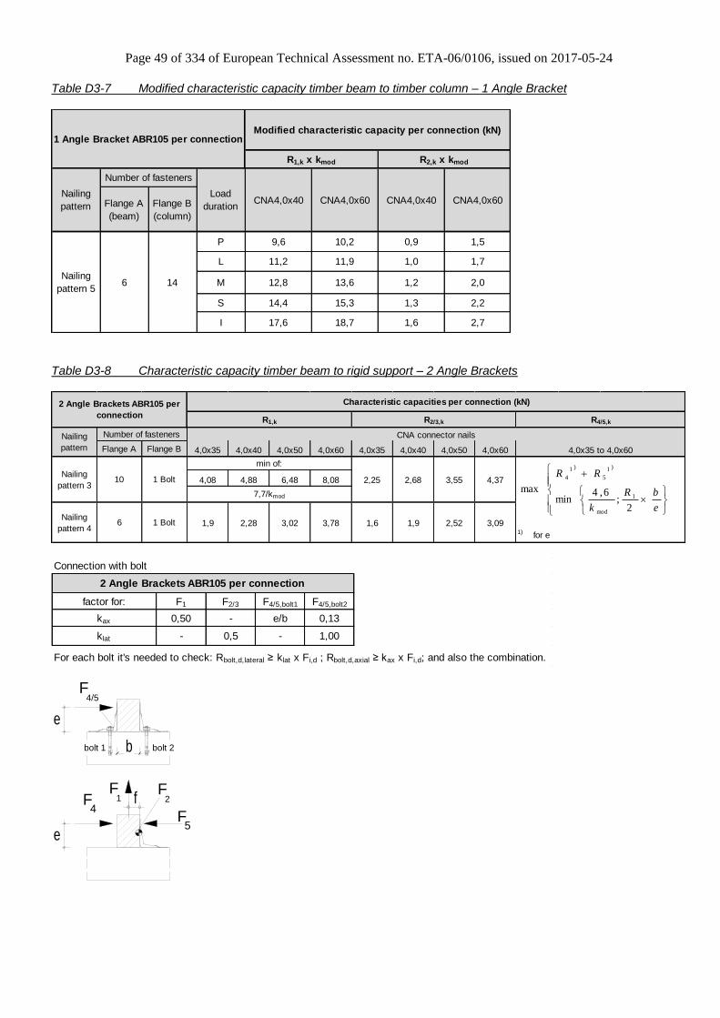
Page 49 of 334 of European Technical Assessment no. ETA-06/0106, issued on 2017-05-24
Table D3-7 Modified characteristic capacity timber beam to timber column – 1 Angle Bracket
Flange A
(beam)
Flange B
(column)
P 9,6 10,2 0,9 1,5
L 11,2 11,9 1,0 1,7
M 12,8 13,6 1,2 2,0
S 14,4 15,3 1,3 2,2
I 17,6 18,7 1,6 2,7
CNA4,0x60
6 14Nailing
pattern 5
1 Angle Bracket ABR105 per connectionModified characteristic capacity per connection (kN)
R1,k x kmod R2,k x kmod
Nailing
pattern
Number of fasteners
Load
durationCNA4,0x40 CNA4,0x60 CNA4,0x40
Table D3-8 Characteristic capacity timber beam to rigid support – 2 Angle Brackets
Flange A Flange B 4,0x35 4,0x40 4,0x50 4,0x60 4,0x35 4,0x40 4,0x50 4,0x60
4,08 4,88 6,48 8,08 2,25 2,68 3,55 4,37
1,9 2,28 3,02 3,78 1,6 1,9 2,52 3,091) for e
R4/5,k
4,0x35 to 4,0x60
Characteristic capacities per connection (kN)
CNA connector nails
R1,k
Nailing
pattern 4
R2/3,k
min of:
7,7/kmod
Nailing
pattern 3
Nailing
pattern
2 Angle Brackets ABR105 per
connection
Number of fasteners
10 1 Bolt
6 1 Bolt
e
bR
k
RR
2;
6,4min
max1
mod
)1
5
)1
4
Connection with bolt
factor for: F1 F2/3 F4/5,bolt1 F4/5,bolt2
kax 0,50 - e/b 0,13
klat - 0,5 - 1,00
For each bolt it's needed to check: Rbolt,d,lateral ≥ klat x Fi,d ; Rbolt,d,axial ≥ kax x Fi,d; and also the combination.
2 Angle Brackets ABR105 per connection
F1
F2fF
4
e5
F
e
F4/5
b bolt 2bolt 1

Page 50 of 334 of European Technical Assessment no. ETA-06/0106, issued on 2017-05-24
Table D3-9 Characteristic capacity timber beam to rigid support – 1 Angle Bracket
Flange A Flange B 4,0x35 4,0x40 4,0x50 4,0x60 4,0x35 4,0x40 4,0x50 4,0x60
245 294 392 490
173 208 277 347
e is to insert in [mm]; e≥ 10mm
negativ values shall not be considered
1 Angle Bracket ABR105 per
connection
Characteristic capacities per connection (kN)
R1,k R4,k R2/3,k R5,k
Nailing
pattern
Number of fasteners CNA connector nails
4,0x35 to 4,0x60 4,0x35 to 4,0x60
45,8 / ((f +81) x kmod) 45,28/ (e x kmod)
Half of the values for a connection with 2
ABR105, if the timber is prevented from
rotation, otherwise R_2/3=0,0kN
X1=
X2=
Nailing
pattern 310 1 Bolt
Nailing
pattern 46 1 Bolt
mod
265;
101
2;
99,9
1min
keemm
X
mme
X
Connection with bolt
factor for: F1 F2/3 F4 F5
kax 1,00 - e/15 e/80
klat - - 1,00 1,00
For each bolt it's needed to check: Rbolt,d,lateral ≥ klat x Fi,d ; Rbolt,d,axial ≥ kax x Fi,d; and also the combination.
1 Angle Bracket ABR105 per connection

Page 51 of 334 of European Technical Assessment no. ETA-06/0106, issued on 2017-05-24
Annex D4 – AB105
Product Name:
Product
Name
Material reference
acc. to clause II-1 Alternative product names
AB105 Steel ref. 1 France: AB105-R, Germany: 105 o/R
AB105S Steel ref. 2 -
AB105S2 Steel ref. 3 -
Connector Size Range:
Model no. Dimensions [mm] Holes flange A Holes flange B
A B C Thickness Ø5 Ø11 Ø5 Ø11
AB105 103 103 90 3,0 8 3 11 3
Drawing:
Nailing pattern:
Nailing pattern 1 Nailing pattern 2 Nailing pattern 3 Nailing pattern 4 Nailing pattern 5
Flange A:
Flange B:
Beam to beam
Maximum nailing Beam to beam
Minimum nailing Beam (A)
to column (B) Trimmer
connection Beam (A) to
rigid support (B)

Page 52 of 334 of European Technical Assessment no. ETA-06/0106, issued on 2017-05-24
Table D4-1 Modified characteristic capacity timber beam to timber beam – 2 Angle Brackets
4,0x40 4,0x60 4,0x40 4,0x60 4,0x40 4,0x60
1,9·b+75 2,6·b+80
e-2,5 e-2,5
max 5,5 max 7,1
2,0·b+76 2,9·b+83
e-2,5 e-2,5
max 6,4 max 8,3
2,2·b+77 3,2·b+85
e-2,5 e-2,5
max 7,3 max 9,4
2,4·b+79 3,4·b+87
e-2,5 e-2,5
max 8,2 max 10,3
2,7·b+82 4,0·b+92
e-2,5 e-2,5
max 10,1 max 11,4
2,9·b+83 4,3·b+94
e-2,5 e-2,5
max 8,4 max 8,4
3,3·b+86 4,9·b+99
e-2,5 e-2,5
max 9,1 max 9,1
3,6·b+89 5,5·b+104
e-2,5 e-2,5
max 9,7 max 9,7
4,0·b+92 6,1·b+108
e-2,5 e-2,5
max 10,3 max 10,3
4,7·b+97 6,8·b+114
e-2,5 e-2,5
max 11,4 max 11,4
b and e are in mm
Wane may not occur under the angle brackets.
16,4
10,6 14,6
2 Angle Brackets AB105
per connectionModified characteristic capacity per connection (kN)
I
7,3
9,3 12,76,6 9,8
11,0
14,6 20,0
12,0
6,3
8,0 10,9
6,9
13,6
5,8 8,7
Nailing
pattern 1
P
L
M
S 8,0 12,2
9,4
L
3,2 6,1
3,6 6,8
5,5 8,1 4,5 8,3
4,4
I
Nailing
pattern 2
Nailing
pattern
Load
duration
R1,k x kmod R2/3,k x kmod
4,5
2,8
2,4
4,8
R4/5,k x kmod
CNA Connector nail
3,6 5,1
4,1 5,7 5,3
8 11
M
S
P
Number of fasteners
Flange A Flange B
4 6
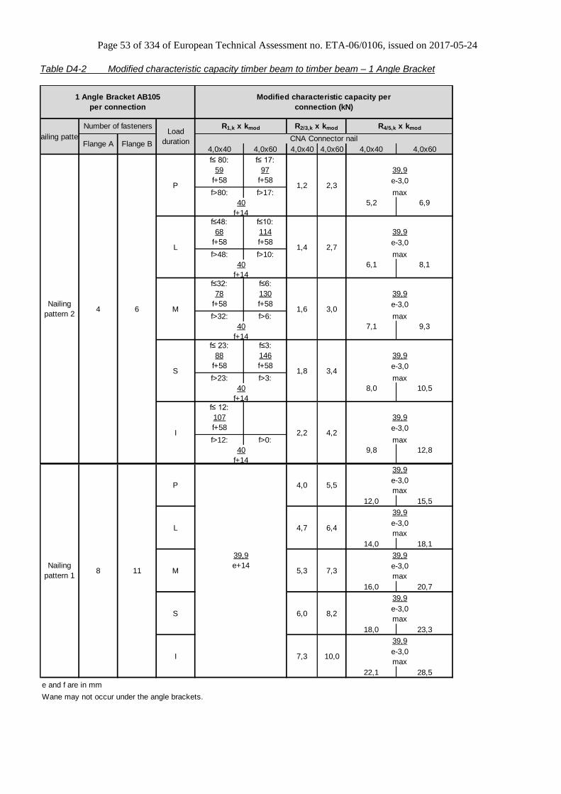
Page 53 of 334 of European Technical Assessment no. ETA-06/0106, issued on 2017-05-24
Table D4-2 Modified characteristic capacity timber beam to timber beam – 1 Angle Bracket
4,0x40 4,0x60 4,0x40 4,0x60 4,0x40 4,0x60
f≤ 80: f≤ 17:
59 97
f+58 f+58
f>80: f>17:
5,2 6,9
f≤48: f≤10:
68 114
f+58 f+58
f>48: f>10:
6,1 8,1
f≤32: f≤6:
78 130
f+58 f+58
f>32: f>6:
7,1 9,3
f≤ 23: f≤3:
88 146
f+58 f+58
f>23: f>3:
8,0 10,5
f≤ 12:
107
f+58
f>12: f>0:
9,8 12,8
12,0 15,5
14,0 18,1
16,0 20,7
18,0 23,3
22,1 28,5
e and f are in mm
Wane may not occur under the angle brackets.
Number of fasteners
Flange A Flange B
4 6
8 11
39,9
e-3,0
maxI 7,3 10,0
Nailing
pattern 1
S
M
L
P
39,9
e-3,0
max6,0 8,2
e-3,0
max5,3 7,3
e+14
39,9
e-3,0
40
f+14
4,2
39,9
e-3,0
P
L
M
I
1,6
1,4
40
1,2
f+14
40
max
Nailing patternLoad
duration
R1,k x kmod R2/3,k x kmod R4/5,k x kmod
3,4
39,9
Nailing
pattern 2
2,2
e-3,0S 1,8
max
40
f+14
max4,7 6,4
39,9
39,9
e-3,04,0 5,5
max
39,9
max
2,7
39,9
e-3,0
max
3,0
39,9
e-3,0
1 Angle Bracket AB105
per connection
Modified characteristic capacity per
connection (kN)
2,3
f+14
f+14
CNA Connector nail
40
max
39,9
e-3,0
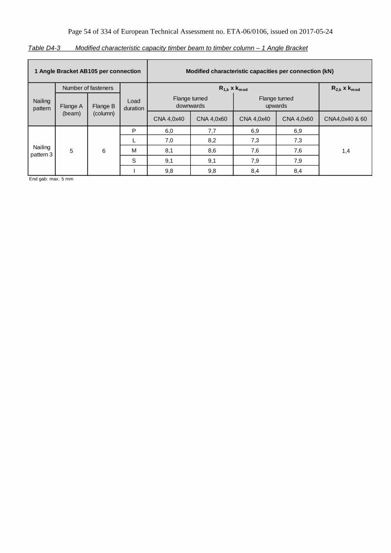
Page 54 of 334 of European Technical Assessment no. ETA-06/0106, issued on 2017-05-24
Table D4-3 Modified characteristic capacity timber beam to timber column – 1 Angle Bracket
R2,k x kmod
CNA 4,0x40 CNA 4,0x60 CNA 4,0x40 CNA 4,0x60 CNA4,0x40 & 60
P 6,0 7,7 6,9 6,9
L 7,0 8,2 7,3 7,3
M 8,1 8,6 7,6 7,6
S 9,1 9,1 7,9 7,9
I 9,8 9,8 8,4 8,4
End gab: max. 5 mm
Flange turned
downwards
Flange turned
upwards
5 6 1,4Nailing
pattern 3
R1,k x kmod
Modified characteristic capacities per connection (kN)1 Angle Bracket AB105 per connection
Nailing
pattern
Number of fasteners
Load
durationFlange A
(beam)
Flange B
(column)
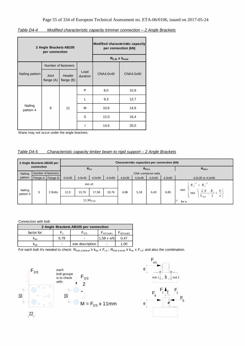
Page 55 of 334 of European Technical Assessment no. ETA-06/0106, issued on 2017-05-24
Table D4-4 Modified characteristic capacity trimmer connection – 2 Angle Brackets
Joist
flange (A)
Header
flange (B)
P 8,0 10,9
L 9,3 12,7
M 10,6 14,6
S 12,0 16,4
I 14,6 20,0
Wane may not occur under the angle brackets.
Nailing
pattern 4
Modified characteristic capacity
per connection (kN)2 Angle Brackets AB105
per connection
Nailing pattern
Number of fasteners
Load
durationCNA4,0x40 CNA4,0x60
8 11
R2,3k x kmod
Table D4-5 Characteristic capacity timber beam to rigid support – 2 Angle Brackets
Flange A Flange B 4,0x35 4,0x40 4,0x50 4,0x60 4,0x35 4,0x40 4,0x50 4,0x60
12,3 13,76 17,58 19,76 4,86 5,18 6,43 6,85
1) for e
4,0x35 to 4,0x60
Nailing
pattern 55 2 Bolts
min of:
11,3/kmod
2 Angle Brackets AB105 per
connection
Characteristic capacities per connection (kN)
R1,k R2/3,k R4/5,k
Nailing
pattern
Number of fasteners CNA connector nails
e
bR
k
RR
2;
0,2min
max1
mod
)1
5
)1
4
Connection with bolt
factor for: F1 F2/3 F4/5,bolt1 F4/5,bolt2
kax 0,79 - 1,58 x e/b 0,47
klat - see description - 1,00
For each bolt it's needed to check: Rbolt,d,lateral ≥ klat x Fi,d ; Rbolt,d,axial ≥ kax x Fi,d; and also the combination.
2 Angle Brackets AB105 per connection
2/3F
22
50 50
2/3M = F x 11mm
2/3Fwith:
bolt groupe
is to check
each
2
F1
F2fF
4
e5
F
e
F4/5
b bolt 2bolt 1
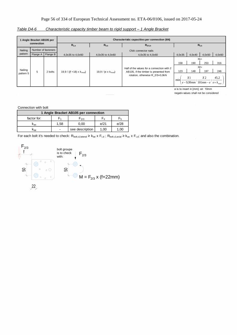
Page 56 of 334 of European Technical Assessment no. ETA-06/0106, issued on 2017-05-24
Table D4-6 Characteristic capacity timber beam to rigid support – 1 Angle Bracket
Flange A Flange B 4,0x35 4,0x40 4,0x50 4,0x60
158 190 253 316
123 148 197 246
e is to insert in [mm]; e≥ 10mm
negativ values shall not be considered
Half of the values for a connection with 2
AB105, if the timber is prevented from
rotation, otherwise R_2/3=0,0kN
X1=
X2=
4,0x35 to 4,0x60
Nailing
pattern
Number of fasteners CNA connector nails
4,0x35 to 4,0x60 4,0x35 to 4,0x60
Nailing
pattern 55 2 bolts 19,9 / ((f +18) x kmod) 19,9 / (e x kmod)
1 Angle Bracket AB105 per
connection
Characteristic capacities per connection (kN)
R1,k R4,k R2/3,k R5,k
mod
2,45;
101
2;
99,9
1min
keemm
X
mme
X
Connection with bolt
factor for: F1 F2/3 F4 F5
kax 1,58 0,00 e/21 e/28
klat - see description 1,00 1,00
For each bolt it's needed to check: Rbolt,d,lateral ≥ klat x Fi,d ; Rbolt,d,axial ≥ kax x Fi,d; and also the combination.
1 Angle Bracket AB105 per connection
2/3F
2/3M = F x (f+22mm)
2/3Fwith:
bolt groupe
is to check
22
50 50
f

Page 57 of 334 of European Technical Assessment no. ETA-06/0106, issued on 2017-05-24
Annex D5 – ABR70 Product Name:
Product
Name
Material reference
acc. to clause II-1 Alternative product names
ABR70 Steel ref. 1 France: EB/7070, Germany: 70 m/R
ABR70S Steel ref. 2 -
ABR70S2 Steel ref. 3 -
Connector Size Range:
Model no. Dimensions [mm] Holes flange A Holes flange B
A B C Thickness Ø5 Ø8,5 Ø5 Ø8,5
ABR70 70 70 55 2,0 6 1 6 1
Drawing:
Nailing pattern:
Nailing pattern 1 Nailing pattern 2
Flange A:
Flange B:
Beam to beam
Maximum nailing Beam to beam
Minimum nailing

Page 58 of 334 of European Technical Assessment no. ETA-06/0106, issued on 2017-05-24
Table D5-1 Modified characteristic capacity timber beam to timber beam – 2 Angle Brackets
4,0x40 4,0x60 4,0x40 4,0x60 4,0x40 4,0x60
1,04·b+155 1,48·b+161
e e
2,1 3,0 max 3,5 max 5,0
1,18·b+157 1,72·b+165
e e
2,4 3,4 max 4,0 max 5,9
1,18·b+157 1,97·b+169
e e
2,4 3,9 max 4,0 max 6,7
1,33·b+159 2,21·b+172
e e
2,7 4,3 max 4,5 max 7,5
1,63·b+164 2,71·b+180
e e
3,3 5,1 max 5,5 max 9,2
1,60·b+179 2,66·b+206
e e
2,5 4,1 max 6,0 max 9,9
1,86·b+186 3,10·b+217
e e
3,1 4,6 max 7,0 max 11,6
2,13·b+192 3,54·b+228
e e
3,4 5,2 max 8,0 max 13,2
2,40·b+199 3,99·b+239
e e
3,7 5,8 max 9,0 max 14,9
2,93·b+212 4,87·b+261
e e
4,4 6,9 max 10,9 max 18,2
b and e are in mm.
4 6
Number of fasteners
Flange A Flange B
When the purlin has a wane on the side towards the Angle Bracket with an extent from the bottom up to the lower nail
the value in the grey square is valid.
4,3 7,1
3,5 5,1
4,0 5,8
8,05,5
4,8
L
M
Nailing
pattern 1
P
L
M
S
I
4 4
S
I
2,7 4,4
3,3 5,4
3,4 4,8
Nailing
pattern
Load
duration
R1,k x kmod R2/3,k x kmod
2,4 3,4
2,9 4,1
R4/5,k x kmod
CNA Connector nail
2,1 3,0
Nailing
pattern 2
P
2,4 3,93,9 5,5
6,2
4,4
4,5 6,6
4,4 6,2
5,3 7,5
2 Angle Brackets ABR70
per connectionModified characteristic capacity per connection (kN)
8,0
5,9 9,7
3,03,2 5,3
3,7
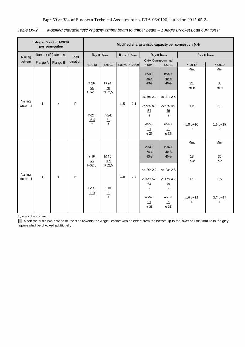
Page 59 of 334 of European Technical Assessment no. ETA-06/0106, issued on 2017-05-24
Table D5-2 Modified characteristic capacity timber beam to timber beam – 1 Angle Bracket Load duration P
4,0x40 4,0x60 4,0x40 4,0x60 4,0x40 4,0x60 4,0x40 4,0x60
Min: Min:
e<40: e<40:
28,5 40,6
f≤ 26: f≤ 24: 40-e 40-e 21 30
54 76 55-e 55-e
f+62,5 f+62,5
e≤ 26: 2,2 e≤ 27: 2,8
26<e≤ 53: 27<e≤ 48: 1,5 2,1
54 76
f>26: f>24: e e
15,5 21
f f e>53: e>48: 1,0·b+10 1,5·b+15
21 21 e e
e-35 e-35
Min: Min:
e<40: e<40:
24,4 40,6
f≤ 16: f≤ 15: 40-e 40-e 18 30
66 109 55-e 55-e
f+62,5 f+62,5
e≤ 29: 2,2 e≤ 28: 2,8
29<e≤ 52: 28<e≤ 48: 1,5 2,5
64 79
f>16: f>15: e e
13,3 21
f f e>52: e>48: 1,6·b+32 2,7·b+53
21 21 e e
e-35 e-35
b, e and f are in mm.
P
P
4 4
4 6
Number of fasteners
Flange A Flange B
R2/3,k x kmod R4,k x kmod R5,k x kmod
2,1
2,21,5
1,5
When the purlin has a wane on the side towards the Angle Bracket with an extent from the bottom up to the lower nail the formula in the grey
square shall be checked additionelly.
1 Angle Bracket ABR70
per connectionModified characteristic capacity per connection (kN)
Nailing
pattern
Load
duration
Nailing
pattern 2
Nailing
pattern 1
CNA Connector nail
R1,k x kmod

Page 60 of 334 of European Technical Assessment no. ETA-06/0106, issued on 2017-05-24
Table D5-3 Modified characteristic capacity timber beam to timber beam – 1 Angle Bracket Load duration L
4,0x40 4,0x60 4,0x40 4,0x60 4,0x40 4,0x60 4,0x40 4,0x60
Min: Min:
e<40: e<40:
32,6 47,4
f≤ 26: f≤ 19: 40-e 40-e 24 34
61 89 55-e 55-e
f+62,5 f+62,5
e≤ 24: 2,6 e≤ 24: 3,3
24<e≤ 49: 24<e≤ 48: 1,7 2,4
61 79
f>26: f>19: e e
17,8 21
f f e>49: e>48: 1,2·b+12 1,7·b+17
21 21 e e
e-35 e-35
Min: Min:
e<40: e<40:
28,5 47,4
f≤ 16: f≤ 12: 40-e 40-e 21 34
77 127 55-e 55-e
f+62,5 f+62,5
e≤ 29: 2,6 e≤ 24: 3,3
29<e≤ 49: 24<e≤ 48: 1,8 3,0
74 79
f>16: f>12: e e
15,5 21
f f e>49: e>48: 1,9·b+37 3,1·b+62
21 21 e e
e-35 e-35
b, e and f are in mm.
4 6 L
Number of fasteners
Flange A Flange B
4 4 L
When the purlin has a wane on the side towards the Angle Bracket with an extent from the bottom up to the lower nail the formula in the grey
square shall be checked additionelly.
1 Angle Bracket ABR70
per connectionModified characteristic capacity per connection (kN)
Nailing
pattern
Load
duration
Nailing
pattern 2
Nailing
pattern 1
CNA Connector nail
R5,k x kmodR1,k x kmod R2/3,k x kmod R4,k x kmod
2,61,7
2,41,7

Page 61 of 334 of European Technical Assessment no. ETA-06/0106, issued on 2017-05-24
Table D5-4 Modified characteristic capacity timber beam to timber beam – 1 Angle Bracket Load duration M
4,0x40 4,0x60 4,0x40 4,0x60 4,0x40 4,0x60 4,0x40 4,0x60
Min: Min:
e<40: e<40:
32,6 54,1 24 39
f≤ 26: f≤ 16: 40-e 40-e 55-e 55-e
61 102
f+62,5 f+62,5
e≤ 21: 2,9 e≤ 21: 3,8
21<e≤ 48: 21<e≤ 48: 1,7 2,8
61 79
f>26: f>16: e e
17,8 21
f f e>48: e>48: 1,2·b+12 2,0·b+20
21 21 e e
e-35 e-35
Min: Min:
e<40: e<40:
32,6 54,1 24 39
f≤ 16: f≤ 11: 40-e 40-e 55-e 55-e
88 146
f+62,5 f+62,5
e≤ 27: 2,9 e≤ 21: 3,8
27<e≤ 48: 21<e≤ 48: 2 3,4
79 79
f>16: f>11: e e
17,8 21
f f e>48: e>48: 2,1·b+43 3,5·b+71
21 21 e e
e-35 e-35
b, e and f are in mm.
4 6 M
Number of fasteners
Flange A Flange B
4 4 M
R2/3,k x kmod R4,k x kmod R5,k x kmod
2 2,9
1,9 2,7
When the purlin has a wane on the side towards the Angle Bracket with an extent from the bottom up to the lower nail the formula in the gray
square shall be checked additionelly.
1 Angle Bracket ABR70
per connectionModified characteristic capacity per connection (kN)
Nailing
pattern
Load
duration
Nailing
pattern 2
Nailing
pattern 1
CNA Connector nail
R1,k x kmod

Page 62 of 334 of European Technical Assessment no. ETA-06/0106, issued on 2017-05-24
Table D5-5 Modified characteristic capacity timber beam to timber beam – 1 Angle Bracket Load duration S
4,0x40 4,0x60 4,0x40 4,0x60 4,0x40 4,0x60 4,0x40 4,0x60
Min: Min:
e<40: e<40:
36,6 60,9 27 44
f≤ 26: f≤ 14: 40-e 40-e 55-e 55-e
69 115
f+62,5 f+62,5
e≤ 21: 3,3 e≤ 19: 4,2
21<e≤ 48: 19<e≤ 48: 1,9 3,1
69 79
f>26: f>14: e e
20 21
f f e>48: e>48: 1,3·b+13 2,2·b+22
21 21 e e
e-35 e-35
Min: Min:
e<40: e<40:
36,6 60,9 27 44
f≤ 16: f≤ 9: 40-e 40-e 55-e 55-e
99 164
f+62,5 f+62,5
e≤ 24: 3,3 e≤ 19: 4,2
24<e≤ 48: 19<e≤ 48: 2,3 3,8
79 79
f>16: f>9: e e
20 21
f f e>48: e>48: 2,4·b+48 4,0·b+80
21 21 e e
e-35 e-35
b, e and f are in mm.
4 6 S
Number of fasteners
Flange A Flange B
4 4 S 2,2 3,1
CNA Connector nail
R1,k x kmod R2/3,k x kmod R4,k x kmod R5,k x kmod
When the purlin has a wane on the side towards the Angle Bracket with an extent from the bottom up to the lower nail the formula in the grey
square shall be checked additionelly.
1 Angle Bracket ABR70
per connectionModified characteristic capacity per connection (kN)
Nailing
pattern
Load
duration
Nailing
pattern 2
Nailing
pattern 12,2 3,3
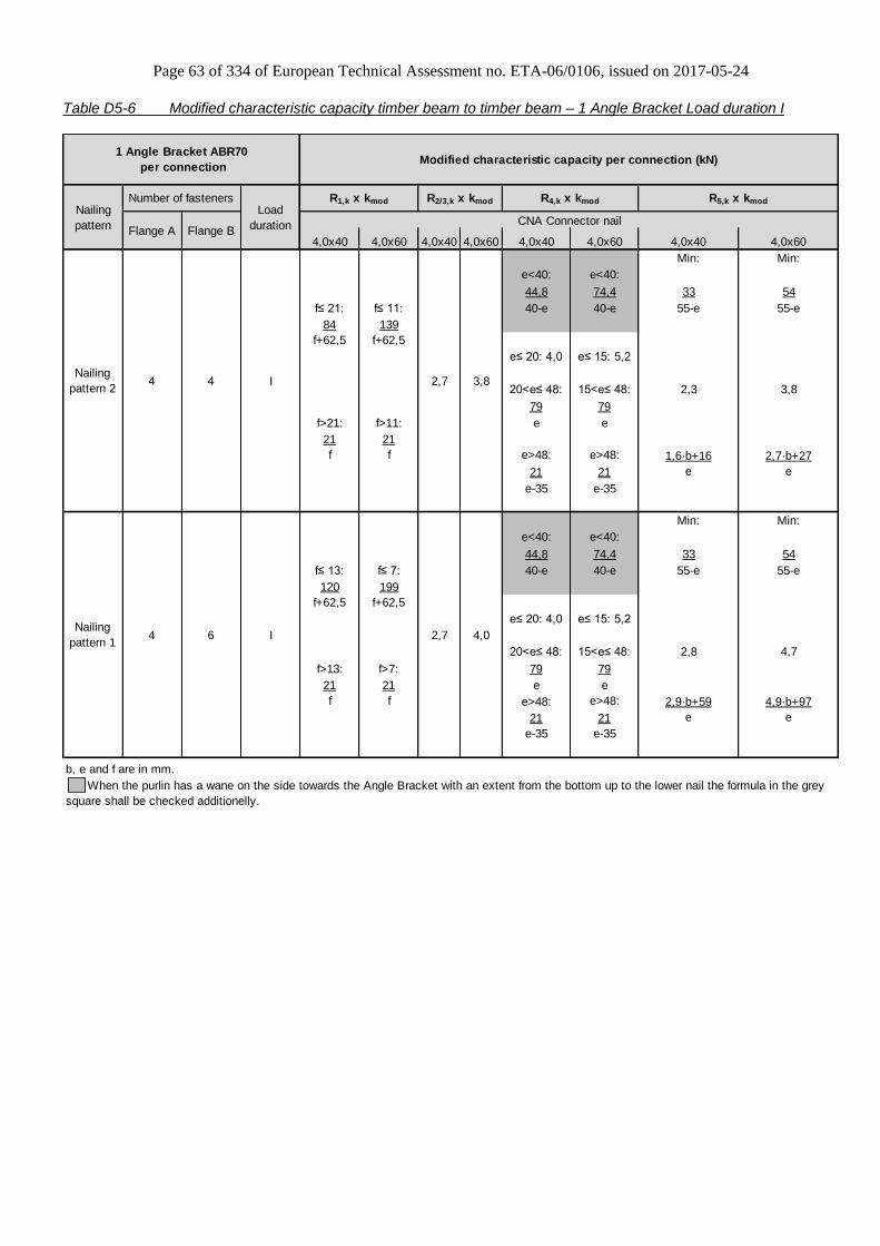
Page 63 of 334 of European Technical Assessment no. ETA-06/0106, issued on 2017-05-24
Table D5-6 Modified characteristic capacity timber beam to timber beam – 1 Angle Bracket Load duration I
4,0x40 4,0x60 4,0x40 4,0x60 4,0x40 4,0x60 4,0x40 4,0x60
Min: Min:
e<40: e<40:
44,8 74,4 33 54
f≤ 21: f≤ 11: 40-e 40-e 55-e 55-e
84 139
f+62,5 f+62,5
e≤ 20: 4,0 e≤ 15: 5,2
20<e≤ 48: 15<e≤ 48: 2,3 3,8
79 79
f>21: f>11: e e
21 21
f f e>48: e>48: 1,6·b+16 2,7·b+27
21 21 e e
e-35 e-35
Min: Min:
e<40: e<40:
44,8 74,4 33 54
f≤ 13: f≤ 7: 40-e 40-e 55-e 55-e
120 199
f+62,5 f+62,5
e≤ 20: 4,0 e≤ 15: 5,2
20<e≤ 48: 15<e≤ 48: 2,8 4,7
f>13: f>7: 79 79
21 21 e e
f f e>48: e>48: 2,9·b+59 4,9·b+97
21 21 e e
e-35 e-35
b, e and f are in mm.
Nailing
pattern 14 6 I
Number of fasteners
Flange A Flange B
4 4 I
R2/3,k x kmod R4,k x kmod R5,k x kmod
2,7
2,7 3,8
4,0
When the purlin has a wane on the side towards the Angle Bracket with an extent from the bottom up to the lower nail the formula in the grey
square shall be checked additionelly.
1 Angle Bracket ABR70
per connectionModified characteristic capacity per connection (kN)
Nailing
pattern
Load
duration
Nailing
pattern 2
CNA Connector nail
R1,k x kmod

Page 64 of 334 of European Technical Assessment no. ETA-06/0106, issued on 2017-05-24
Annex D6 – AB70
Product Name:
Product
Name
Material reference
acc. to clause II-1 Alternative product names
AB70 Steel ref. 1 Germany: 70 o/R
AB70S Steel ref. 2 -
AB70S2 Steel ref. 3 -
Connector Size Range:
Model no. Dimensions [mm] Holes flange A Holes flange B
A B C Thickness Ø5 Ø8,5 Ø5 Ø8,5
AB70 70 70 55 2,0 4 2 7 1
Drawing:
Nailing pattern:
Nailing pattern 1 Nailing pattern 2
Flange A:
Flange B:
Beam to beam
Maximum nailing Beam to beam
Minimum nailing
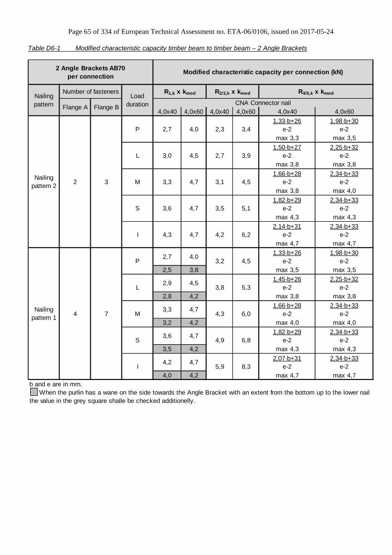
Page 65 of 334 of European Technical Assessment no. ETA-06/0106, issued on 2017-05-24
Table D6-1 Modified characteristic capacity timber beam to timber beam – 2 Angle Brackets
4,0x40 4,0x60 4,0x40 4,0x60 4,0x40 4,0x60
1,33·b+26 1,98·b+30
e-2 e-2
max 3,3 max 3,5
1,50·b+27 2,25·b+32
e-2 e-2
max 3,8 max 3,8
1,66·b+28 2,34·b+33
e-2 e-2
max 3,8 max 4,0
1,82·b+29 2,34·b+33
e-2 e-2
max 4,3 max 4,3
2,14·b+31 2,34·b+33
e-2 e-2
max 4,7 max 4,7
1,33·b+26 1,98·b+30
e-2 e-2
2,5 3,8 max 3,5 max 3,5
1,45·b+26 2,25·b+32
e-2 e-2
2,8 4,2 max 3,8 max 3,8
1,66·b+28 2,34·b+33
e-2 e-2
3,2 4,2 max 4,0 max 4,0
1,82·b+29 2,34·b+33
e-2 e-2
3,5 4,2 max 4,3 max 4,3
2,07·b+31 2,34·b+33
e-2 e-2
4,0 4,2 max 4,7 max 4,7
b and e are in mm.
Flange B
2 3
4 7
2 Angle Brackets AB70
per connectionModified characteristic capacity per connection (kN)
3,0
When the purlin has a wane on the side towards the Angle Bracket with an extent from the bottom up to the lower nail
the value in the grey square shalle be checked additionelly.
4,74,3
3,6
4,2 6,2
Number of fasteners
Nailing
pattern 1M
Load
duration
3,3 4,7
4,7
P
L
M
Flange A
Nailing
pattern
R1,k x kmod
CNA Connector nail
R2/3,k x kmod R4/5,k x kmod
4,52,7
S
2,7
3,1Nailing
pattern 2
2,3 3,4
2,7 3,9
4,5
4,5
3,5 5,1
I
5,3
P 3,2
2,9
4,0
4,5
3,6 4,7
3,3
4,0
L 3,8
4,34,7
I 5,9
S
8,34,2 4,7
6,0
4,9 6,8
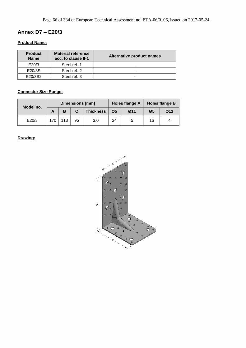
Page 66 of 334 of European Technical Assessment no. ETA-06/0106, issued on 2017-05-24
Annex D7 – E20/3
Product Name:
Product
Name
Material reference
acc. to clause II-1 Alternative product names
E20/3 Steel ref. 1 -
E20/3S Steel ref. 2 -
E20/3S2 Steel ref. 3 -
Connector Size Range:
Model no. Dimensions [mm] Holes flange A Holes flange B
A B C Thickness Ø5 Ø11 Ø5 Ø11
E20/3 170 113 95 3,0 24 5 16 4
Drawing:

Page 67 of 334 of European Technical Assessment no. ETA-06/0106, issued on 2017-05-24
Nailing pattern:
Nailing pattern 1 Nailing pattern 2 Nailing pattern 3 Nailing pattern 4
Flange A:
Flange B:
Beam to beam
Maximum nailing Beam to beam
Minimum nailing Trimmer connection
Column (A) to beam (B)
Nailing pattern 5 Nailing pattern 6
Flange A:
Flange B:
Beam (A) to rigid
support (B) Column (A) to rigid
support (B)

Page 68 of 334 of European Technical Assessment no. ETA-06/0106, issued on 2017-05-24
Table D7-1 Modified characteristic capacity timber beam to timber beam – 2 Angle Brackets
4,0x35 4,0x50 4,0x35 4,0x50
4,4 7,1
3,2 5,2
5,1 8,2
3,8 6,1
5,9 9,4
4,3 7,0
6,6 10,6
4,9 7,8
8,1 12,9
6,0 9,6
b and e are in mm.
9
24 16
Number of fasteners
Flange A Flange B
2 Angle Brackets E20/3
per connection
L 14,210,5
3,3 5,3
3,9 6,2
Modified characteristic capacity per connection
(kN)
12
P
When the purlin has a wane on the side towards the Angle Bracket with an extent form the
bottom up to the lower nail the value in the gray square is valid.
P
Nailing
pattern
Load
duration CNA Connector nail
R1,k x kmod R2/3,k x kmod
12,19,0
Nailing
pattern 1
Nailing
pattern 212,0M
S
I
I
S
M
L
29,2
23,917,9
15,9 21,2
21,8
18,613,9
15,9
18,2
22,2
13,5
11,9
16,2
16,56,1 9,7
4,4 7,1
5,0 7,9

Page 69 of 334 of European Technical Assessment no. ETA-06/0106, issued on 2017-05-24
Table D7-2 Modified characteristic capacity timber beam to timber beam – 1 Angle Bracket
4,0x35 4,0x50 4,0x35 4,0x50
f≤ 58: f≤ 80:
119 162
f+73 f+73
f>58: f>80:
53 85
f f
f≤ 65: f≤ 88:
131 181
f+73 f+73
f>65: f>88:
62 99
f f
f≤ 71: f≤ 94:
143 200
f+73 f+73
f>71: f>94:
71 113
f f
f≤ 77: f≤ 101:
155 219
f+73 f+73
f>77: f>101:
79 127
f f
f≤ 87: f≤ 112:
179 257
f+73 f+73
f>87: f>112:
97 155
f f
f are in mm.
Wane may not occur under the angle bracket.
P
CNA Connector nail
R1,k x kmod
8,1
8,3
9,1
7,15,3
9
Number of fastenersNailing
pattern
11,1
6,8
6,0
R2/3,k x kmod
6,14,5
Load
durationFlange A Flange B
Nailing
pattern 2
1 Angle Brackets E20/3
per connection
Modified characteristic capacity
per connection (kN)
M
S
I
L
12
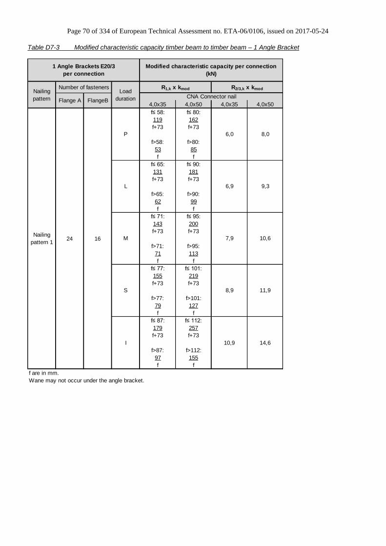
Page 70 of 334 of European Technical Assessment no. ETA-06/0106, issued on 2017-05-24
Table D7-3 Modified characteristic capacity timber beam to timber beam – 1 Angle Bracket
4,0x35 4,0x50 4,0x35 4,0x50
f≤ 58: f≤ 80:
119 162
f+73 f+73
f>58: f>80:
53 85
f f
f≤ 65: f≤ 90:
131 181
f+73 f+73
f>65: f>90:
62 99
f f
f≤ 71: f≤ 95:
143 200
f+73 f+73
f>71: f>95:
71 113
f f
f≤ 77: f≤ 101:
155 219
f+73 f+73
f>77: f>101:
79 127
f f
f≤ 87: f≤ 112:
179 257
f+73 f+73
f>87: f>112:
97 155
f f
f are in mm.
Wane may not occur under the angle bracket.
24 16Nailing
pattern 1
P 6,0
S 8,9
M 7,9
6,9
I 10,9 14,6
8,0
L 9,3
10,6
11,9
Nailing
pattern
Load
duration
R1,k x kmod R2/3,k x kmod
CNA Connector nail
1 Angle Brackets E20/3
per connection
Modified characteristic capacity per connection
(kN)
Number of fasteners
Flange A FlangeB

Page 71 of 334 of European Technical Assessment no. ETA-06/0106, issued on 2017-05-24
Table D7-4 Modified characteristic capacity timber column to timber beam – 2 Angle Brackets
4,0x35 4,0x50 4,0x35 4,0x50
P 3,3 5,3 7,1 9,5
L 3,9 6,2 8,2 11,1
M 4,4 7,1 9,4 12,7
S 5,0 7,9 10,6 14,3
I 6,1 9,7 12,9 17,5
Flange B
13 8
2 Angle Brackets E20/3
per connection
Modified characteristic capacity
per connection (kN)
Nailing
pattern 4
Nailing
pattern
Load
duration CNA Connector nail
R1,k x kmod R2/3,k x kmodNumber of fasteners
Flange A
Table D7-5 Modified characteristic capacity timber beam to rigid support – 2 Angle Brackets
4,0x35 4,0x50 4,0x35 4,0x50
Requirement for bolts - see declaration under table D7-6.
Number of fasteners
Flange A Flange B
24 4 Bolts
When the purlin has a wane on the side towards the Angle Bracket with an extent from the
bottom up to the lower nail the value in the grey square is valid.
P
Nailing
pattern 5
Nailing
pattern
23,4 26,8
42,9 56,8
37,5 49,7
32,2 42,6
40,3 61,6
59,0 78,1
48,3 63,9
25,6 39,2
29,3 44,8
I
27,3L
33,0 50,4
31,3
31,2 35,8
35,1 40,2
42,9 49,2
2 Angle Brackets E20/3
per connection
Modified characteristic capacity per connection
(kN)
Load
durationCNA Connector nail
S
R1,k x kmod R2/3,k x kmod
M
22,0 33,6
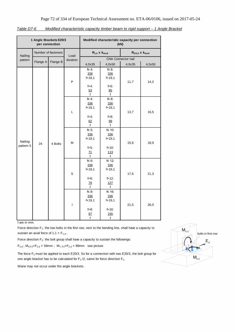
Page 72 of 334 of European Technical Assessment no. ETA-06/0106, issued on 2017-05-24
Table D7-6 Modified characteristic capacity timber beam to rigid support – 1 Angle Bracket
4,0x35 4,0x50 4,0x35 4,0x50
f≤ 4: f≤ 6:
336 336
f+19,1 f+19,1
f>4: f>6:
53 85
f f
f≤ 4: f≤ 8:
336 336
f+19,1 f+19,1
f>4: f>8:
62 99
f f
f≤ 5: f≤ 10:
336 336
f+19,1 f+19,1
f>5: f>10:
71 113
f f
f≤ 6: f≤ 12:
336 336
f+19,1 f+19,1
f>6: f>12:
79 127
f f
f≤ 8: f≤ 16:
336 336
f+19,1 f+19,1
f>8: f>16:
97 155
f f
f are in mm.
P
Nailing
pattern 5
11,7 14,2
15,6
Number of fasteners
Flange A Flange B
24 4 Bolts
13,7
I 21,5 26,0
S 17,6
The force F2 must be applied to each E20/3. So for a connection with two E20/3, the bolt group for
one angle bracket has to be calculated for F2 /2, same for force direction F1.
Wane may not occur under the angle brackets.
16,5
M
21,3
Force direction F1: the two bolts in the first row, next to the bending line, shall have a capacity to
sustain an axial force of 1,1 × F1,d .
Force direction F2: the bolt group shall have a capacity to sustain the followings:
F2,d ; MX,F2=F2,d × 59mm ; MY,F2=F2,d × 89mm see picture
18,9
L
1 Angle Brackets E20/3
per connection
Modified characteristic capacity per connection
(kN)
Nailing
pattern
Load
duration
R1,k x kmod R2/3,k x kmod
CNA Connector nail
M Y,F2
X,F2M
F 2,d
bolts in first row

Page 73 of 334 of European Technical Assessment no. ETA-06/0106, issued on 2017-05-24
Table D7-7 Modified characteristic capacity timber column to rigid support – 2 Angle Brackets
Flange A Flange B
Wane may not occur under the angle bracket.
Nailing
pattern 613 4 bolts
Modified characteristic capacities per
connection (kN)
Nailing
pattern
Number of fasteners
Load
durationCNA4,0x35 CNA4,0x50 CNA4,0x35 CNA4,0x50
28,0 32,0
R1,k x kmod R2/3,k x kmod
1 Angle Bracket E20/3 per connection
24,0
17,8 20,4
20,4 23,3
22,9 26,2
P 15,3
L
M
17,5
24,1 32,0
21,1 28,0
18,1
33,2 44,0I
27,2 36,0S
Table D7-8 Modified characteristic capacity timber to timber – trimmer connection
Flange A Flange B
P 7,6 11,6 3,8 5,8
L 8,9 13,5 4,4 6,7
M 10,1 15,4 5,1 7,7
S 11,4 17,4 5,7 8,7
I 13,9 21,2 7,0 10,6
Wane may not occur under the angle brackets.
Nailing
pattern 318
R2/3,k x kmod R2/3,k x kmod
1 or 2 Angle Bracket(-s) E20/3 per
connection
CNA4,0x35 CNA4,0x50 CNA4,0x35
Modified characteristic capacity
per connection (kN)
Load
duration
16
Nailing
pattern
Number of fasteners
2 Angle Brackets E20/3
per connection
1 Angle Bracket E20/3
per connection
CNA4,0x50
1) The capacities are based on the assumption that the bolts have a characteritic lateral capacitt of
20 kN and a characteristic axial capacity of 22 kN. If one of the characteristic capacities of the
choosen bolts is smaller, the cpacity of the connection shall be reduced proportionally.

Page 74 of 334 of European Technical Assessment no. ETA-06/0106, issued on 2017-05-24
Annex D8 – E9/2.5
Product Name:
Product
Name
Material reference
acc. to clause II-1 Alternative product names
E9/2.5 Steel ref. 1 -
E9/2.5S Steel ref. 2 -
E9/2.5S2 Steel ref. 3 -
Connector Size Range:
Model no. Dimensions [mm] Holes flange A Holes flange B
A B C Thickness Ø5 Ø11 Ø5 Ø11
E9/2.5 154 152,5 65 2,5 14 2 14 2
Drawing:
Nailing pattern:
Nailing pattern 1 Nailing pattern 2 Nailing pattern 3 Nailing pattern 4 Nailing pattern 5
Flange A:
Flange B:
Beam to beam
Maximum nailing Beam to beam
Minimum nailing Trimmer
connection Column (A) to beam (B)
Beam (A) to rigid support (B)
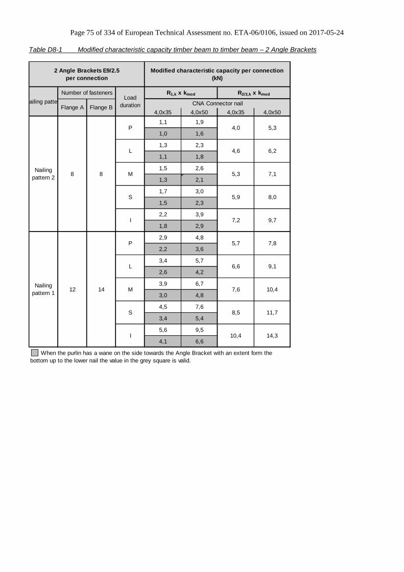
Page 75 of 334 of European Technical Assessment no. ETA-06/0106, issued on 2017-05-24
Table D8-1 Modified characteristic capacity timber beam to timber beam – 2 Angle Brackets
4,0x35 4,0x50 4,0x35 4,0x50
1,1 1,9
1,0 1,6
1,3 2,3
1,1 1,8
1,5 2,6
1,3 2,1
1,7 3,0
1,5 2,3
2,2 3,9
1,8 2,9
2,9 4,8
2,2 3,6
3,4 5,7
2,6 4,2
3,9 6,7
3,0 4,8
4,5 7,6
3,4 5,4
5,6 9,5
4,1 6,6
8 8
12 14
Nailing patternLoad
duration
R1,k x kmod R2/3,k x kmod
CNA Connector nail
Number of fasteners
Flange A Flange B
Nailing
pattern 2
P 4,0 5,3
L 4,6 6,2
M 5,3 7,1
M 7,6 10,4
S 5,9 8,0
I 7,2 9,7
P 5,7 7,8
L 6,6 9,1
When the purlin has a wane on the side towards the Angle Bracket with an extent form the
bottom up to the lower nail the value in the grey square is valid.
2 Angle Brackets E9/2.5
per connection
Modified characteristic capacity per connection
(kN)
S 8,5 11,7
I 10,4 14,3
Nailing
pattern 1

Page 76 of 334 of European Technical Assessment no. ETA-06/0106, issued on 2017-05-24
Table D8-2 Modified characteristic capacity timber beam to timber beam – 1 Angle Bracket
4,0x35 4,0x50 4,0x35 4,0x50
f≤ 24: f≤ 31:
45 60
f+62,5 f+62,5
f>24: f>31:
12 20
f f
f≤ 26: f≤ 27:
49 67
f+62,5 f+62,5
f>26: f>27:
15 20
f f
f≤ 28: f≤ 24:
53 74
f+62,5 f+62,5
f>28: f>24:
17 20
f f
f≤ 30: f≤ 21:
58 80
f+62,5 f+62,5
f>30: f>21:
19 20
f f
f≤ 28: f≤ 17:
66 94
f+62,5 f+62,5
f>28: f>17:
20 20
f f
f are in mm.
Wane may not occur under the angle bracket.
Flange B
P
Nailing
pattern
Load
duration CNA Connector nail
R1,k x kmod R2/3,k x kmod
8 8
Number of fasteners
Flange A
4,9
3,0
2,6
2,72,0
3,12,3
1 Angle Brackets E9/2.5
per connection
Modified characteristic capacity per connection
(kN)
3,5
3,6
4,0
Nailing
pattern 2
L
M
S
I

Page 77 of 334 of European Technical Assessment no. ETA-06/0106, issued on 2017-05-24
Table D8-3 Modified characteristic capacity timber beam to timber beam – 1 Angle Bracket
4,0x35 4,0x50 4,0x35 4,0x50
f≤ 25: f≤ 38:
35 43
f+44 f+44
f>25: f>38:
12 20
f f
f≤ 29: f≤ 33:
37 47
f+44 f+44
f>29: f>33:
15 20
f f
f≤ 32: f≤ 29:
39 51
f+44 f+44
f>32: f>29:
17 20
f f
f≤ 35: f≤ 26:
42 55
f+44 f+44
f>35: f>26:
19 20
f f
f≤ 34: f≤ 21:
47 62
f+44 f+44
f>34: f>21:
20 20
f f
f are in mm.
Wane may not occur under the angle bracket.
12 14
S 4,3 5,8
I 5,2 7,1
Nailing
pattern 1
P 2,8 3,9
L 3,3 4,5
M 3,8 5,2
1 Angle Brackets E9/2.5
per connection
Modified characteristic capacity per connection
(kN)
Nailing
pattern
Load
duration
R1,k x kmod R2/3,k x kmod
CNA Connector nail
Number of fasteners
Flange A Flange B

Page 78 of 334 of European Technical Assessment no. ETA-06/0106, issued on 2017-05-24
Table D8-4 Modified characteristic capacity timber column to timber beam – 1 Angle Bracket
Flange A
(column)
Flange B
(beam)
3,0
3,9
3,5 5,9I
2,8 4,7
6,1 9,4
3,5
7,7
6,8
5,0
P 3,3
L
M
S
1,8 5,1
4,4
Modified characteristic capacity per connection
(kN)
R1,k x kmod R2,k x kmod
Number of fasteners
Load
durationCNA4,0x50
2 Angle Brackets E9/2.5 per connection
6,0
Nailing
pattern 41410
CNA4,0x35 CNA4,0x50 CNA4,0x35Nailing
pattern
2,4 4,1
2,1
Table D8-5 Modified characteristic capacity trimmer connection
Flange A Flange B
P 5,7 7,8 2,8 3,9
L 6,6 9,1 3,3 4,5
M 7,6 10,4 3,8 5,2
S 8,5 11,7 4,3 5,8
I 10,4 14,3 5,2 7,1
CNA4,0x35 CNA4,0x50
12 14
Modified characteristic capacity
per connection (kN)
2 Angle Brackets E9/2.5
per connection
1 Angle Bracket E9/2.5
per connection
R2/3,k x kmodR2/3,k x kmod
1 or 2 Angle Bracket(-s) E9/2.5 per
connection
Nailing
pattern
Number of fasteners
Load
durationCNA4,0x35 CNA4,0x50
Nailing
pattern 3
Table D8-6 Characteristic capacity timber beam to rigid support – 2 Angle Brackets
Characteristic capacities
per connection (kN)
R1,k
Flange A Flange B
Nailing
pattern 512 1 Bolt 6,0
The bolt group must be able to resist to R 1,tension of bolt,d= F1,d x 2,7
Nailing
pattern
Number of fasteners
CNA4,0x35
2 Angle Brackets E9/2.5 per
connection

Page 79 of 334 of European Technical Assessment no. ETA-06/0106, issued on 2017-05-24
Annex D9 – E9S/2.5
Product Name:
Product
Name
Material reference
acc. to clause II-1 Alternative product names
E9S/2.5 Steel ref. 1 -
E9S/2.5S Steel ref. 2 -
E9S/2.5S2 Steel ref. 3 -
Connector Size Range:
Model no.
Dimensions [mm] Holes flange A Holes flange B
A B C Thicknes
s Ø5 Ø11 Ø5 Ø11
E9S/2.5 94 152,5 65 2,5 8 1 14 2
Drawing:
Nailing pattern:
Nailing pattern 1 Nailing pattern 2 Nailing pattern 3 Nailing pattern 4
Flange A:
Flange B:
Beam to beam
Maximum nailing Beam to beam
Minimum nailing Trimmer connection
Column (A) to beam (B)

Page 80 of 334 of European Technical Assessment no. ETA-06/0106, issued on 2017-05-24
Table D9-1 Modified characteristic capacity timber beam to timber beam – 2 Angle Brackets
4,0x35 4,0x50 4,0x35 4,0x50
1,0 1,7
0,6 1,0
1,2 2,1
0,8 1,2
1,4 2,4
0,9 1,4
1,6 2,8
1,0 1,6
2,0 3,5
1,2 1,9
2,7 4,5
2,1 3,4
3,2 5,4
2,5 4,0
3,7 6,2
2,9 4,6
4,2 7,1
3,2 5,2
5,3 8,9
3,9 6,3
8 6
12 8
Number of fasteners
Flange A Flange B
I 9,7 13,0
7,0 9,5
7,9 10,7
5,4
5,3 7,1
6,2 8,3
S
P
L
M
4,1 5,2
6,1
7,0
7,9
9,6
4,8
When the purlin has a wane on the side towards the Angle Bracket with an extent form the
bottom up to the lower nail the value in the grey square is valid.
6,1
7,5
Nailing
pattern 1
Nailing
pattern 2
P
L
M
S
I
2 Angle Brackets E9S/2.5
per connection
Modified characteristic capacity per connection
(kN)
Nailing
pattern
Load
duration
R1,k x kmod R2/3,k x kmod
CNA Connector nail

Page 81 of 334 of European Technical Assessment no. ETA-06/0106, issued on 2017-05-24
Table D9-2 Modified characteristic capacity timber beam to timber beam – 1 Angle Bracket
4,0x35 4,0x50 4,0x35 4,0x50
f≤ 28: f≤ 17:
83 120
f+84 f+84
f>28: f>17:
20 20
f f
f≤ 24: f≤ 15:
93 137
f+84 f+84
f>24: f>15:
20 20
f f
f≤ 21: f≤ 13:
103 154
f+84 f+84
6
f>21: f>13:
20 20
f f
f≤ 18: f≤ 11:
114 170
f+84 f+84
f>18: f>11:
20 20
f f
f≤ 15: f≤ 9:
134 204
f+84 f+84
f>15: f>9:
20 20
f f
f are in mm.
Wane may not occur under the angle bracket.
P
Nailing
pattern
Load
duration
3,1
2,7
3,1
Number of fasteners
Flange A Flange B
8
1 Angle Bracket E9S/2.5
per connection
Modified characteristic capacity per connection
(kN)
R2/3,k x kmod
2,62,0
3,5
2,4
CNA Connector nail
R1,k x kmod
Nailing
pattern 2
3,7
3,9
M
S
I
L
4,8
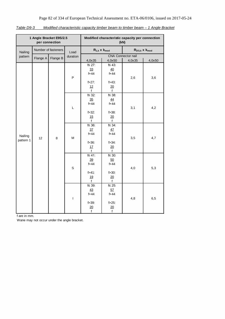
Page 82 of 334 of European Technical Assessment no. ETA-06/0106, issued on 2017-05-24
Table D9-3 Modified characteristic capacity timber beam to timber beam – 1 Angle Bracket
4,0x35 4,0x50 4,0x35 4,0x50
f≤ 27: f≤ 43:
33 40
f+44 f+44
f>27: f>43:
12 20
f f
f≤ 32: f≤ 38:
35 44
f+44 f+44
f>32: f>38:
15 20
f f
f≤ 36: f≤ 34:
37 47
f+44 f+44
f>36: f>34:
17 20
f f
f≤ 41: f≤ 30:
39 50
f+44 f+44
f>41: f>30:
19 20
f f
f≤ 39: f≤ 25:
43 57
f+44 f+44
f>39: f>25:
20 20
f f
f are in mm.
Wane may not occur under the angle bracket.
12 8
Nailing
pattern
Load
duration
R1,k x kmod R2/3,k x kmod
CNA Connector nail
1 Angle Bracket E9S/2.5
per connection
Modified characteristic capacity per connection
(kN)
Number of fasteners
Flange A Flange B
Nailing
pattern 1
P 2,6 3,6
L 3,1 4,2
M 3,5 4,7
S 4,0 5,3
I 4,8 6,5

Page 83 of 334 of European Technical Assessment no. ETA-06/0106, issued on 2017-05-24
Table D9-4 Modified characteristic capacity timber column to timber beam – 1 Angle Bracket
Flange A
(beam)
Flange B
(column)
5,6
Modified characteristic capacity per connection
(kN)
Nailing
pattern
Number of fastenersLoad
durationCNA4,0x35 CNA4,0x50 CNA4,0x35 CNA4,0x50
2,0
7,7 10,6
R1,k x kmod R2,k x kmod
2 Angle Brackets E9S/2.5 per connection
8 10
4,9 6,8
S
7,7
6,3 8,7
4,2
L
M
5,8
2,3 3,9
P
3,3
1,7 2,8
Nailing
pattern 4
3,3 5,5I
2,6 4,4
Table D9-5 Modified characteristic capacity trimmer connection
Flange A Flange B
P 4,1 5,2 2,0 2,6
L 4,8 6,1 2,4 3,1
M 5,4 7,0 2,7 3,5
S 6,1 7,9 3,1 3,9
I 7,5 9,6 3,7 4,8
CNA4,0x35 CNA4,0x50
Nailing
pattern 3
R2/3,k x kmod
2 Angle Brackets E9S/2.5
per connection
1 or 2 Angle Bracket(-s) E9S/2.5 per
connection
8 10
Modified characteristic capacity per connection (kN)
1 Angle Bracket E9S/2.5
per connection
R2/3,k x kmod
Nailing
pattern
Number of fasteners
Load
durationCNA4,0x35 CNA4,0x50
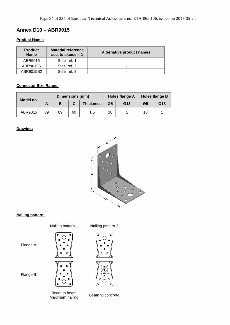
Page 84 of 334 of European Technical Assessment no. ETA-06/0106, issued on 2017-05-24
Annex D10 – ABR9015
Product Name:
Product
Name
Material reference
acc. to clause II-1 Alternative product names
ABR9015 Steel ref. 1 -
ABR9015S Steel ref. 2 -
ABR9015S2 Steel ref. 3 -
Connector Size Range:
Model no. Dimensions [mm] Holes flange A Holes flange B
A B C Thickness Ø5 Ø13 Ø5 Ø13
ABR9015 89 89 60 1,5 10 1 10 1
Drawing:
Nailing pattern:
Nailing pattern 1 Nailing pattern 2
Flange A:
Flange B:
Beam to beam
Maximum nailing Beam to concrete

Page 85 of 334 of European Technical Assessment no. ETA-06/0106, issued on 2017-05-24
Table D10-1 Modified characteristic capacity timber beam to timber beam – 2 Angle Brackets
R1,k x kmod R2/3,k x kmod R4/5,k x kmod
4,1·b+210
e
max 19,4
4,5·b+215
e
max 22,6
4,9·b+219
e
max 25,7
5,3·b+224
e
max 28,8
6,2·b+227
e
max 35,1
Wane may occur under the angle brackets.
Number of fasteners
Flange A Flange B
8 10
CSA Connector screw
5,0x40
Modified characteristic capacity
per connection (kN)
Nailing
pattern 1
Nailing
pattern
2 Angle Bracket ABR9015
per connection
14,4 11,5
9,3 7,3
8,0 6,3
11,8 9,4
10,6 8,4
I
Load
duration
P
L
M
S
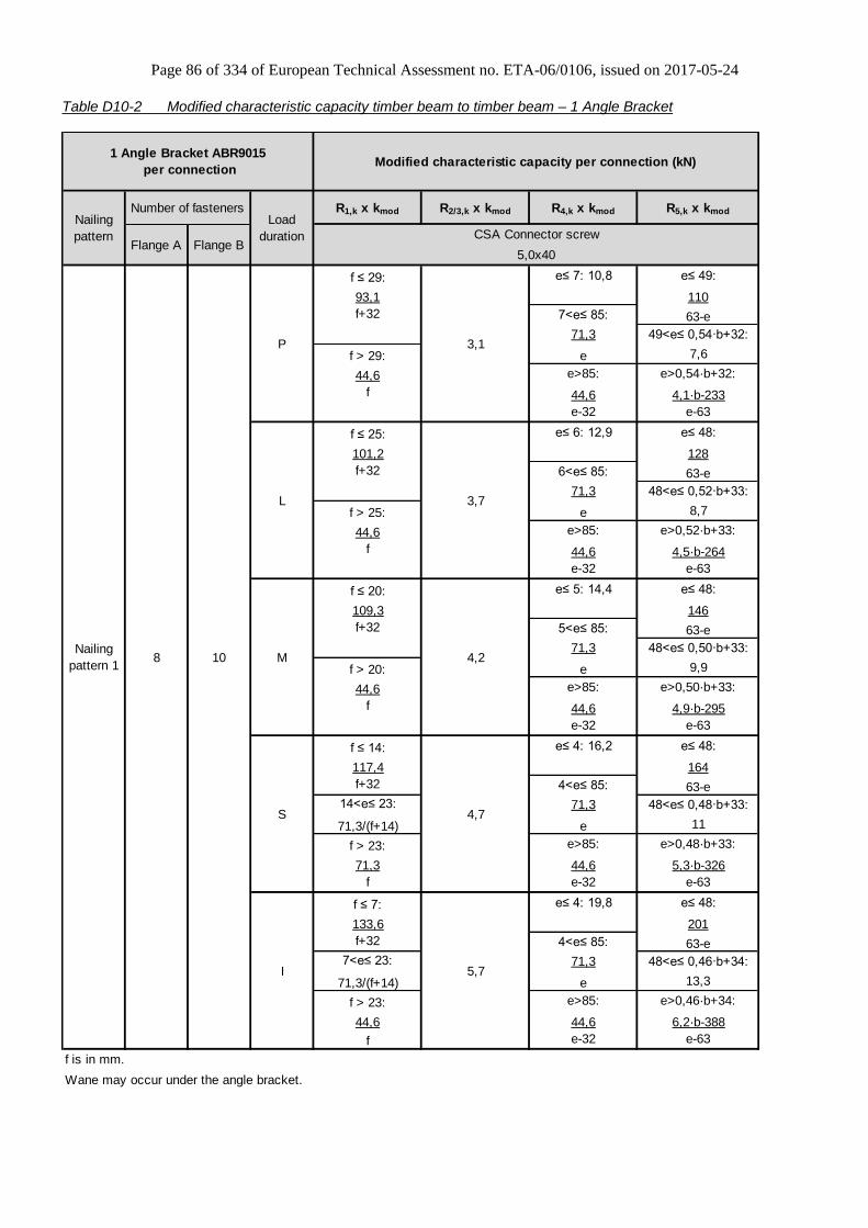
Page 86 of 334 of European Technical Assessment no. ETA-06/0106, issued on 2017-05-24
Table D10-2 Modified characteristic capacity timber beam to timber beam – 1 Angle Bracket
R1,k x kmod R2/3,k x kmod R4,k x kmod R5,k x kmod
f ≤ 29: e≤ 7: 10,8 e≤ 49:
93,1 110
f+32 7<e≤ 85: 63-e
71,3 49<e≤ 0,54·b+32:
f > 29: e 7,6
44,6 e>85: e>0,54·b+32:
f 44,6 4,1·b-233
e-32 e-63
f ≤ 25: e≤ 6: 12,9 e≤ 48:
101,2 128
f+32 6<e≤ 85: 63-e
71,3 48<e≤ 0,52·b+33:
f > 25: e 8,7
44,6 e>85: e>0,52·b+33:
f 44,6 4,5·b-264
e-32 e-63
f ≤ 20: e≤ 5: 14,4 e≤ 48:
109,3 146
f+32 5<e≤ 85: 63-e
71,3 48<e≤ 0,50·b+33:
f > 20: e 9,9
44,6 e>85: e>0,50·b+33:
f 44,6 4,9·b-295
e-32 e-63
f ≤ 14: e≤ 4: 16,2 e≤ 48:
117,4 164
f+32 4<e≤ 85: 63-e
14<e≤ 23: 71,3 48<e≤ 0,48·b+33:
71,3/(f+14) e 11
f > 23: e>85: e>0,48·b+33:
71,3 44,6 5,3·b-326
f e-32 e-63
f ≤ 7: e≤ 4: 19,8 e≤ 48:
133,6 201
f+32 4<e≤ 85: 63-e
7<e≤ 23: 71,3 48<e≤ 0,46·b+34:
71,3/(f+14) e 13,3
f > 23: e>85: e>0,46·b+34:
44,6 44,6 6,2·b-388
f e-32 e-63
f is in mm.
Wane may occur under the angle bracket.
8 10
1 Angle Bracket ABR9015
per connection
Nailing
pattern 1M 4,2
I 5,7
Modified characteristic capacity per connection (kN)
S 4,7
L
CSA Connector screw
5,0x40
Nailing
pattern
Load
duration
3,7
3,1P
Number of fasteners
Flange A Flange B

Page 87 of 334 of European Technical Assessment no. ETA-06/0106, issued on 2017-05-24
Table D10-3 Modified characteristic capacity timber beam to timber beam – 2 Angle Bracket
4,0x35 4,0x40 4,0x50 4,0x60 4,0x35 4,0x40 4,0x50 4,0x60
Wane may occur under the angle brackets.
Number of fasteners
Flange A Flange B
8 10
4,3
5,0
5,7
6,4
6,5
7,3
8,97,8
6,84,4
P
Nailing
pattern
Load
duration CNA Connector nail
R1,k x kmod
Nailing
pattern 1
5,6
M
S
I
L
2,2 2,6 3,3 4,1
10,7
5,7
5,0
R2/3,k x kmod
5,83,8
7,8
6,9
8,7
4,8
2,9 3,8 4,7
6,0
2,8 3,3 4,3 5,4
Modified characteristic capacity per connection (kN)2 Angle Bracket ABR9015
per connection
3,7 4,5 5,9 7,3
3,1 3,7 4,8
2,5

Page 88 of 334 of European Technical Assessment no. ETA-06/0106, issued on 2017-05-24
Table D10-4 Modified characteristic capacity timber beam to timber beam – 1 Angle Bracket
4,0x35 4,0x40 4,0x50 4,0x60 4,0x35 4,0x40 4,0x50 4,0x60
f ≤ 8 : f ≤ 10 : f ≤ 13 : f ≤ 16 :
57 59 64 69
f + 32 f + 32 f + 32 f + 32
f > 8 : f > 10 : f > 13 : f > 16 :
11,3 13,8 18,2 22,9
f f f f
f ≤ 9 : f ≤ 12 : f ≤ 15 : f ≤ 19 :
59 62 67 73
f + 32 f + 32 f + 32 f + 32
f > 9 : f > 12 : f > 15 : f > 19 :
13,2 16,1 21,3 26,7
f f f f
f ≤ 10 : f ≤ 13 : f ≤ 17 : f ≤ 21 :
61 64 70 77
f + 32 f + 32 f + 32 f + 32
f > 10 : f > 13 : f > 17 : f > 21 :
15,1 18,4 24,3 30,5
f f f f
f ≤ 12 : f ≤ 15 : f ≤ 19 : f ≤ 24 :
62,6 66,4 73 81
f + 32 f + 32 f + 32 f + 32
f > 12 : f > 15 : f > 19 : f > 24 :
17 20,6 27,3 34,3
f f f f
f ≤ 15 : f ≤ 17 : f ≤ 23 : f ≤ 29 :
66,6 71,2 80 89
f + 32 f + 32 f + 32 f + 32
f > 15 : f > 17 : f > 23 : f > 29 :
20,8 25,2 33,4 41,9
f f f f
Wane may occur under the angle bracket.
Flange B
8 10
Modified characteristic capacity per connection (kN)
Nailing
pattern
Load
duration
R1,k x kmod R2/3,k x kmod
CNA Connector nail
1 Angle Bracket ABR9015
per connection
Number of fasteners
Flange A
Nailing
pattern 1
P 1,9 2,1 2,4 2,9
L 2,2 2,5 2,8 3,4
M 2,5 2,8 3,2 3,9
S 2,8 3,2 3,6 4,4
I 3,5 3,9 4,4 5,3
Table D10-5 Characteristic capacity timber beam to concrete – 2 Angle Brackets
2 Angle Brackets ABR9015
per connection
Characteristic capacity per
connection (kN)
Nailing pattern Number of fasteners R1,k
Flange A Flange B
Nailing pattern 2 8 x CNA4,0x40 1 x PHNW-37 *) 13,2
*) In pre-drilled hole Ø5 x 18 mm

Page 89 of 334 of European Technical Assessment no. ETA-06/0106, issued on 2017-05-24
Annex D11 – ABR9020
Product Name:
Product
Name
Material reference
acc. to clause II-1 Alternative product names
ABR9020 Steel ref. 1 -
ABR9020S Steel ref. 2 -
ABR9020S2 Steel ref. 3 -
Connector Size Range:
Model no. Dimensions [mm] Holes flange A Holes flange B
A B C Thickness Ø5 Ø11 Ø5 Ø13
ABR9020 88 88 65 2,0 10 1 10 1
Drawing:
Nailing pattern:
Nailing pattern 1 Nailing pattern 2 Nailing pattern 3 Nailing pattern 4
Flange A:
Flange B:
Beam to beam
Maximum nailing Beam to beam
Minimum nailing Beam (A) to
steel (B) Beam (A) to column (B)

Page 90 of 334 of European Technical Assessment no. ETA-06/0106, issued on 2017-05-24
Table D11-1 Modified characteristic capacity timber beam to timber beam - 2 Angle Brackets
R1,k x kmod R2/3,k x kmod R4/5,k x kmod
4,1·b+210
e
max 19,4
4,5·b+215
e
max 22,6
4,9·b+219
e
max 25,7
5,3·b+224
e
max 28,8
6,2·b+227
e
max 35,1
Wane may occur under the angle brackets.
Number of fasteners
Flange A Flange B
8 10
CSA Connector screw 5,0x40
Modified characteristic capacity
per connection (kN)
Nailing
pattern 1
Nailing
pattern
2 Angle Bracket ABR9015
per connection
14,4 11,5
9,3 7,3
8,0 6,3
11,8 9,4
10,6 8,4
I
Load
duration
P
L
M
S
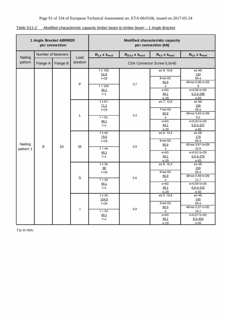
Page 91 of 334 of European Technical Assessment no. ETA-06/0106, issued on 2017-05-24
Table D11-2 Modified characteristic capacity timber beam to timber beam – 1 Angle Bracket
R1,k x kmod R2/3,k x kmod R4,k x kmod R5,k x kmod
f ≤ 100: e≤ 8: 10,8 e≤ 48:
62,8 134
f+29 8<e≤ 63: 65-e
90,9 48<e≤ 0,66·b+28:
f > 100: e 8
49,1 e>63: e>0,66·b+28:
f+1 49,1 5,3·b-298
e-29 e-65
f ≤ 61: e≤ 7: 12,6 e≤ 48:
71,2 156
f+29 7<e≤ 63: 65-e
90,9 48<e≤ 0,63·b+29:
f > 61: e 9,2
49,1 e>63: e>0,63·b+29:
f+1 49,1 5,8·b-337
e-29 e-65
f ≤ 44: e≤ 6: 14,4 e≤ 48:
79,6 178
f+29 6<e≤ 63: 65-e
90,9 45<e≤ 0,61·b+29:
f > 44: e 10,5
49,1 e>63: e>0,61·b+29:
f+1 49,1 6,4·b-376
e-29 e-65
f ≤ 34: e≤ 6: 16,2 e≤ 48:
88 200
f+29 6<e≤ 63: 65-e
90,9 48<e≤ 0,59·b+29:
f > 34: e 11,7
49,1 e>63: e>0,59·b+29:
f+1 49,1 6,9·b-415
e-29 e-65
f ≤ 24: e≤ 5: 19,8 e≤ 48:
104,8 245
f+29 5<e≤ 63: 65-e
90,9 48<e≤ 0,57·b+30:
f > 24: e 14,1
49,1 e>63: e>0,57·b+30:
f+1 49,1 8·b-493
e-29 e-65
f is in mm.
Flange B
Load
duration CSA Connector Screw 5,0x40
Modified characteristic capacity
per connection (kN)
4,3
I 6,8
1 Angle Bracket ABR9020
per connection
S 5,6
Nailing
pattern
Number of fasteners
Flange A
Nailing
pattern 1M 4,9
P 3,7
L
8 10
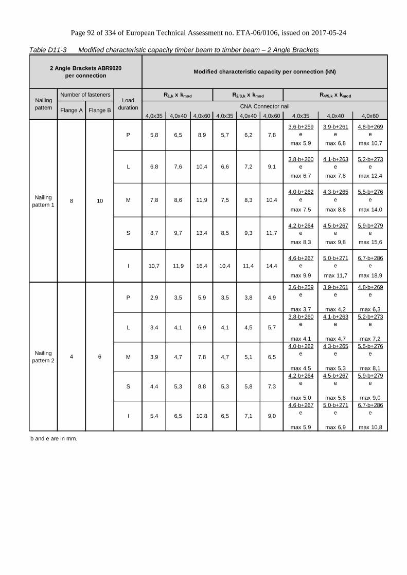
Page 92 of 334 of European Technical Assessment no. ETA-06/0106, issued on 2017-05-24
Table D11-3 Modified characteristic capacity timber beam to timber beam – 2 Angle Brackets
4,0x35 4,0x40 4,0x60 4,0x35 4,0x40 4,0x60 4,0x35 4,0x40 4,0x60
3,6·b+259 3,9·b+261 4,8·b+269
e e e
max 5,9 max 6,8 max 10,7
3,8·b+260 4,1·b+263 5,2·b+273
e e e
max 6,7 max 7,8 max 12,4
4,0·b+262 4,3·b+265 5,5·b+276
e e e
max 7,5 max 8,8 max 14,0
4,2·b+264 4,5·b+267 5,9·b+279
e e e
max 8,3 max 9,8 max 15,6
4,6·b+267 5,0·b+271 6,7·b+286
e e e
max 9,9 max 11,7 max 18,9
3,6·b+259 3,9·b+261 4,8·b+269
e e e
max 3,7 max 4,2 max 6,3
3,8·b+260 4,1·b+263 5,2·b+273
e e e
max 4,1 max 4,7 max 7,2
4,0·b+262 4,3·b+265 5,5·b+276
e e e
max 4,5 max 5,3 max 8,1
4,2·b+264 4,5·b+267 5,9·b+279
e e e
max 5,0 max 5,8 max 9,0
4,6·b+267 5,0·b+271 6,7·b+286
e e e
max 5,9 max 6,9 max 10,8
b and e are in mm.
Number of fasteners
Flange A Flange B
8 10
4 6
2 Angle Brackets ABR9020
per connection
10,4 14,410,7 16,411,9 11,4
8,5 11,7
10,4
Modified characteristic capacity per connection (kN)
6,8 10,47,6 7,2
R4/5,k x kmod
5,7 7,8
L
M
S
7,8 11,98,6
9,1
CNA Connector nail
6,5 6,2
8,7 13,49,7 9,3
7,5 8,3
Nailing
pattern
Load
duration
R1,k x kmod R2/3,k x kmod
Nailing
pattern 1
P
I
5,8 8,9
6,6
Nailing
pattern 2
P 2,9 3,5 5,9 3,5
M 3,9 4,7 7,8
3,8 4,9
L 3,4 4,1 6,9 4,1 4,5 5,7
4,7 5,1 6,5
S 4,4 5,3 8,8 5,3 5,8 7,3
9,0I 5,4 6,5 10,8 6,5 7,1

Page 93 of 334 of European Technical Assessment no. ETA-06/0106, issued on 2017-05-24
Table D11-4 Modified characteristic capacity timber beam to timber beam – 1 Angle Bracket, maximum nailing
Table D11-4.1 R1 & R2/3
4,0x35 4,0x40 4,0x60 4,0x35 4,0x40 4,0x60
f≤ 27: f≤ 32: f≤ 46:
63 69 90
f+40 f+40 f+40
f>27: f>32: f>46:
26,5 31,8 49,4
f+1 f+1 f+1
f≤ 32: f≤ 38: f≤ 38:
68 74 99
f+40 f+40 f+40
f>32: f>38: f>38:
30,9 37 49,4
f+1 f+1 f+1
f≤ 36: f≤ 44: f≤ 32:
72 79 107
f+40 f+40 f+40
f>36: f>44: f>32:
35,3 42,3 49,4
f+1 f+1 f+1
f≤ 41: f≤ 49: f≤ 28:
77 84 116
f+40 f+40 f+40
f>41: f>49: f>28:
39,7 47,6 49,4
f+1 f+1 f+1
f≤ 50: f≤ 41: f≤ 22:
85 95 134
f+40 f+40 f+40
f>50: f>41: f>22:
48,5 49,4 49,4
f+1 f+1 f+1
f, e and b are in mm.
Modified characteristic capacity per connection (kN)
CNA Connector nail
Number of fasteners
Flange A Flange B
8 10
Nailing
pattern
1 Angle Bracket ABR9020
per connection
Nailing
pattern 1
S 4,2 5,9
I 5,2 7,2
2,8
M 3,8 5,2
3,1
3,6
3,9P
L 3,3
4,1
4,7
5,7
Load
duration
4,6
R1,k x kmod R2/3,k x kmod
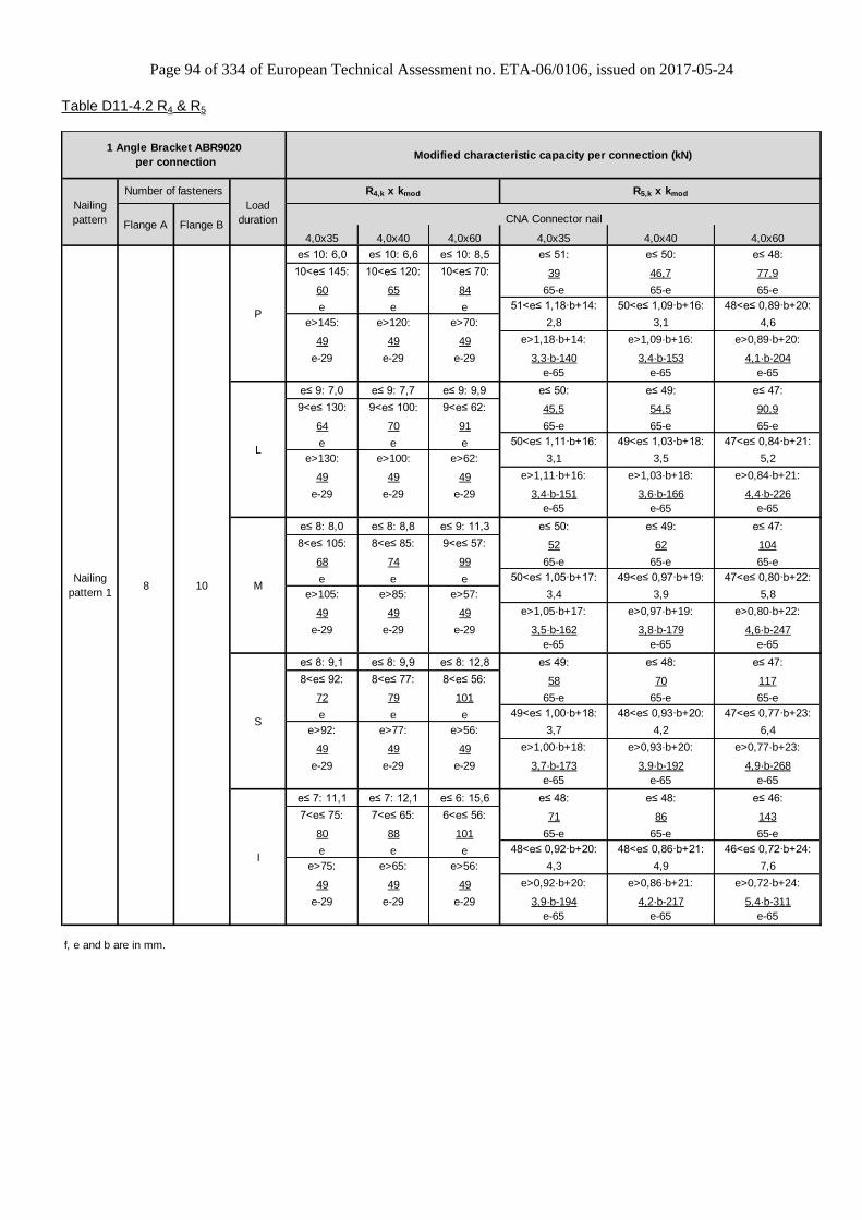
Page 94 of 334 of European Technical Assessment no. ETA-06/0106, issued on 2017-05-24
Table D11-4.2 R4 & R5
4,0x35 4,0x40 4,0x60 4,0x35 4,0x40 4,0x60
e≤ 10: 6,0 e≤ 10: 6,6 e≤ 10: 8,5 e≤ 51: e≤ 50: e≤ 48:
10<e≤ 145: 10<e≤ 120: 10<e≤ 70: 39 46,7 77,9
60 65 84 65-e 65-e 65-e
e e e 51<e≤ 1,18·b+14: 50<e≤ 1,09·b+16: 48<e≤ 0,89·b+20:
e>145: e>120: e>70: 2,8 3,1 4,6
49 49 49 e>1,18·b+14: e>1,09·b+16: e>0,89·b+20:
e-29 e-29 e-29 3,3·b-140 3,4·b-153 4,1·b-204
e-65 e-65 e-65
e≤ 9: 7,0 e≤ 9: 7,7 e≤ 9: 9,9 e≤ 50: e≤ 49: e≤ 47:
9<e≤ 130: 9<e≤ 100: 9<e≤ 62: 45,5 54,5 90,9
64 70 91 65-e 65-e 65-e
e e e 50<e≤ 1,11·b+16: 49<e≤ 1,03·b+18: 47<e≤ 0,84·b+21:
e>130: e>100: e>62: 3,1 3,5 5,2
49 49 49 e>1,11·b+16: e>1,03·b+18: e>0,84·b+21:
e-29 e-29 e-29 3,4·b-151 3,6·b-166 4,4·b-226
e-65 e-65 e-65
e≤ 8: 8,0 e≤ 8: 8,8 e≤ 9: 11,3 e≤ 50: e≤ 49: e≤ 47:
8<e≤ 105: 8<e≤ 85: 9<e≤ 57: 52 62 104
68 74 99 65-e 65-e 65-e
e e e 50<e≤ 1,05·b+17: 49<e≤ 0,97·b+19: 47<e≤ 0,80·b+22:
e>105: e>85: e>57: 3,4 3,9 5,8
49 49 49 e>1,05·b+17: e>0,97·b+19: e>0,80·b+22:
e-29 e-29 e-29 3,5·b-162 3,8·b-179 4,6·b-247
e-65 e-65 e-65
e≤ 8: 9,1 e≤ 8: 9,9 e≤ 8: 12,8 e≤ 49: e≤ 48: e≤ 47:
8<e≤ 92: 8<e≤ 77: 8<e≤ 56: 58 70 117
72 79 101 65-e 65-e 65-e
e e e 49<e≤ 1,00·b+18: 48<e≤ 0,93·b+20: 47<e≤ 0,77·b+23:
e>92: e>77: e>56: 3,7 4,2 6,4
49 49 49 e>1,00·b+18: e>0,93·b+20: e>0,77·b+23:
e-29 e-29 e-29 3,7·b-173 3,9·b-192 4,9·b-268
e-65 e-65 e-65
e≤ 7: 11,1 e≤ 7: 12,1 e≤ 6: 15,6 e≤ 48: e≤ 48: e≤ 46:
7<e≤ 75: 7<e≤ 65: 6<e≤ 56: 71 86 143
80 88 101 65-e 65-e 65-e
e e e 48<e≤ 0,92·b+20: 48<e≤ 0,86·b+21: 46<e≤ 0,72·b+24:
e>75: e>65: e>56: 4,3 4,9 7,6
49 49 49 e>0,92·b+20: e>0,86·b+21: e>0,72·b+24:
e-29 e-29 e-29 3,9·b-194 4,2·b-217 5,4·b-311
e-65 e-65 e-65
f, e and b are in mm.
Modified characteristic capacity per connection (kN)
CNA Connector nail
Number of fasteners
Flange A Flange B
8 10
Nailing
pattern
1 Angle Bracket ABR9020
per connection
Nailing
pattern 1
S
I
M
P
L
R4,k x kmod R5,k x kmod
Load
duration

Page 95 of 334 of European Technical Assessment no. ETA-06/0106, issued on 2017-05-24
Table D11-5 Modified characteristic capacity timber beam to timber beam – 1 Angle Bracket, minimum nailing
Table D11-5.1 R1 & R2/3
4,0x35 4,0x40 4,0x60 4,0x35 4,0x40 4,0x60
f≤ 27: f≤ 33: f≤ 46:
63 69 90
f+40 f+40 f+40
f>27: f>33: f>46:
26,5 31,8 49,4
f+1 f+1 f+1
f≤ 32: f≤ 38: f≤ 38:
68 74 99
f+40 f+40 f+40
f>32: f>38: f>38:
30,9 37,0 49,4
f+1 f+1 f+1
f≤ 36: f≤ 44: f≤ 32:
72 79 107
f+40 f+40 f+40
f>36: f>44: f>32:
35,3 42,3 49,4
f+1 f+1 f+1
f≤ 41: f≤ 49: f≤ 28:
77 84 116
f+40 f+40 f+40
f>41: f>49: f>28:
39,7 47,6 49,4
f+1 f+1 f+1
f≤ 50: f≤ 41: f≤ 22:
85 95 134
f+40 f+40 f+40
f>50: f>41: f>22:
48,5 49,4 49,4
f+1 f+1 f+1
f, e and b are in mm.
Number of fasteners
Flange A Flange B
4 6
Modified characteristic capacity per connection (kN)
CNA Connector nail
2,6
2,9
3,5
Load
duration
2,9
R1,k x kmod R2/3,k x kmod
M 2,4 3,3
1,9
2,2
2,4P
L 2,1
Nailing
pattern
1 Angle Bracket ABR9020
per connection
Nailing
pattern 2
S 2,7 3,7
I 3,2 4,5
1,8
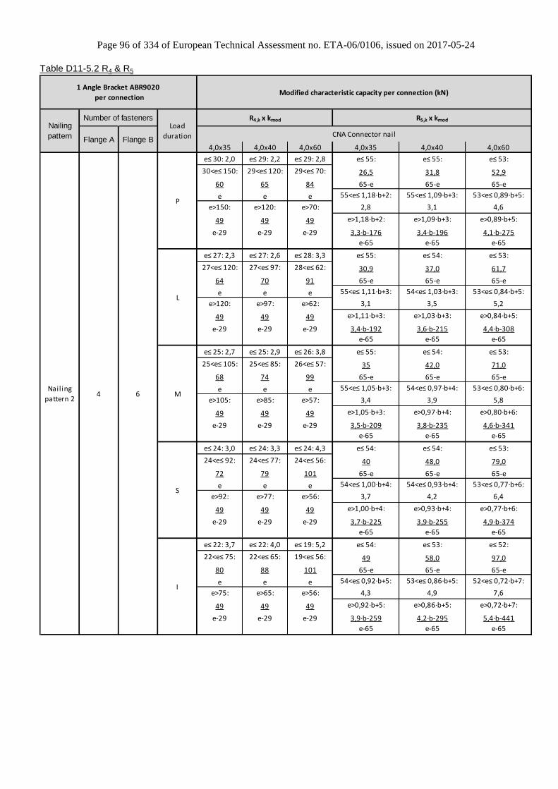
Page 96 of 334 of European Technical Assessment no. ETA-06/0106, issued on 2017-05-24
Table D11-5.2 R4 & R5
4,0x35 4,0x40 4,0x60 4,0x35 4,0x40 4,0x60
e≤ 30: 2,0 e≤ 29: 2,2 e≤ 29: 2,8 e≤ 55: e≤ 55: e≤ 53:
30<e≤ 150: 29<e≤ 120: 29<e≤ 70: 26,5 31,8 52,9
60 65 84 65-e 65-e 65-e
e e e 55<e≤ 1,18·b+2: 55<e≤ 1,09·b+3: 53<e≤ 0,89·b+5:
e>150: e>120: e>70: 2,8 3,1 4,6
49 49 49 e>1,18·b+2: e>1,09·b+3: e>0,89·b+5:
e-29 e-29 e-29 3,3·b-176 3,4·b-196 4,1·b-275
e-65 e-65 e-65
e≤ 27: 2,3 e≤ 27: 2,6 e≤ 28: 3,3 e≤ 55: e≤ 54: e≤ 53:
27<e≤ 120: 27<e≤ 97: 28<e≤ 62: 30,9 37,0 61,7
64 70 91 65-e 65-e 65-e
e e e 55<e≤ 1,11·b+3: 54<e≤ 1,03·b+3: 53<e≤ 0,84·b+5:
e>120: e>97: e>62: 3,1 3,5 5,2
49 49 49 e>1,11·b+3: e>1,03·b+3: e>0,84·b+5:
e-29 e-29 e-29 3,4·b-192 3,6·b-215 4,4·b-308
e-65 e-65 e-65
e≤ 25: 2,7 e≤ 25: 2,9 e≤ 26: 3,8 e≤ 55: e≤ 54: e≤ 53:
25<e≤ 105: 25<e≤ 85: 26<e≤ 57: 35 42,0 71,0
68 74 99 65-e 65-e 65-e
e e e 55<e≤ 1,05·b+3: 54<e≤ 0,97·b+4: 53<e≤ 0,80·b+6:
e>105: e>85: e>57: 3,4 3,9 5,8
49 49 49 e>1,05·b+3: e>0,97·b+4: e>0,80·b+6:
e-29 e-29 e-29 3,5·b-209 3,8·b-235 4,6·b-341
e-65 e-65 e-65
e≤ 24: 3,0 e≤ 24: 3,3 e≤ 24: 4,3 e≤ 54: e≤ 54: e≤ 53:
24<e≤ 92: 24<e≤ 77: 24<e≤ 56: 40 48,0 79,0
72 79 101 65-e 65-e 65-e
e e e 54<e≤ 1,00·b+4: 54<e≤ 0,93·b+4: 53<e≤ 0,77·b+6:
e>92: e>77: e>56: 3,7 4,2 6,4
49 49 49 e>1,00·b+4: e>0,93·b+4: e>0,77·b+6:
e-29 e-29 e-29 3,7·b-225 3,9·b-255 4,9·b-374
e-65 e-65 e-65
e≤ 22: 3,7 e≤ 22: 4,0 e≤ 19: 5,2 e≤ 54: e≤ 53: e≤ 52:
22<e≤ 75: 22<e≤ 65: 19<e≤ 56: 49 58,0 97,0
80 88 101 65-e 65-e 65-e
e e e 54<e≤ 0,92·b+5: 53<e≤ 0,86·b+5: 52<e≤ 0,72·b+7:
e>75: e>65: e>56: 4,3 4,9 7,6
49 49 49 e>0,92·b+5: e>0,86·b+5: e>0,72·b+7:
e-29 e-29 e-29 3,9·b-259 4,2·b-295 5,4·b-441
e-65 e-65 e-65
Modified characteristic capacity per connection (kN)
CNA Connector nail
Number of fasteners
Flange A Flange B
4 6
R4,k x kmod R5,k x kmodLoad
duration
M
P
L
Nailing
pattern
1 Angle Bracket ABR9020
per connection
Nailing
pattern 2
S
I

Page 97 of 334 of European Technical Assessment no. ETA-06/0106, issued on 2017-05-24
Table D11-6 Characteristic capacity timber beam to 6 mm steel beam – 2 Angle Brackets
2 Angle Brackets ABR9020
per connection Characteristic capacity
per connection (kN)
Nailing pattern Number of fasteners R1,k
Flange A Flange B
Nailing pattern 3 8 x CNA4,0x60 4 x PDPA-75 12,1
Table D11-7 1 angle brackets ABR9020, beam to column
1 ABR9020
Characteristic capacity per connection [kN]
R1,k R2,k
4,0x40 4,0x60 4,0x40 4,0x60
Nailing 4+10 see fig. 11-5
7,7 10,4 1,5 2,5
Table D11-8 ABR9020 Slip modulus Kser
2 ABR9020 Kser [kN/mm]
For force Nailing CNA4.0x35 CNA4.0x40 CNA4.0x50 CNA4.0x60
F1 Max 3,9 4,3 5,1 5,9
Min 1,9 2,3 3,1 3,9
F2 Max 1,2 1,4 1,5 1,7
Min 0,6 0,7 0,8 0,9
Table D11-9 Modified characteristic capacity timber beam to timber column – 1 Angle Bracket
1 Angle Bracket ABR9020
per connection
Modified characteristic capacity
per connection (kN)
R1,k x kmod R2,k x kmod
Nailing pattern
Number of Fasteners
Load duration
CNA4,0x40 CNA4,0x60 CNA4,0x40 CNA4,0x60 Flange A (beam)
Flange B (column)
Nailing pattern 4
4 10
P 4,6 6,2 0,9 1,5
L 5,4 7,3 1,1 1,8
M 6,2 8,3 1,2 2,0
S 6,9 9,4 1,4 2,3
I 8,5 11,4 1,7 2,8
General note to capacity tables:
b, e and f are in mm.
Wane may not occur under the angle bracket.
F1 2
F
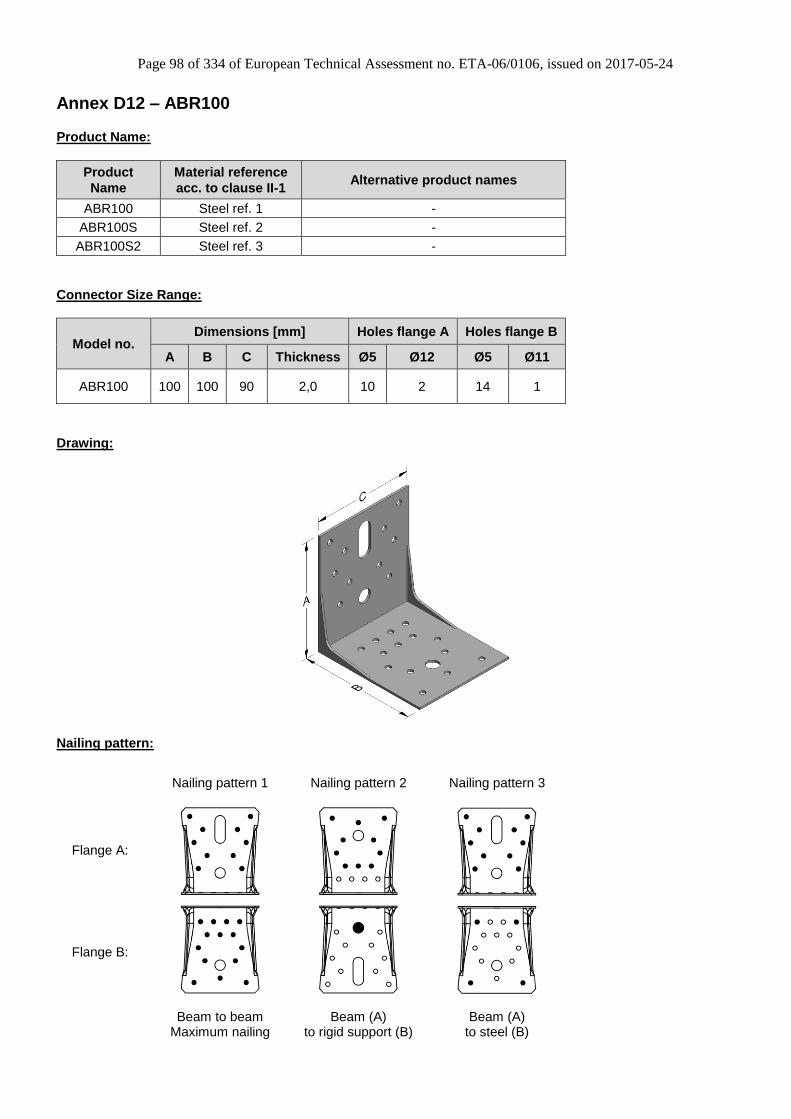
Page 98 of 334 of European Technical Assessment no. ETA-06/0106, issued on 2017-05-24
Annex D12 – ABR100
Product Name:
Product
Name
Material reference
acc. to clause II-1 Alternative product names
ABR100 Steel ref. 1 -
ABR100S Steel ref. 2 -
ABR100S2 Steel ref. 3 -
Connector Size Range:
Model no. Dimensions [mm] Holes flange A Holes flange B
A B C Thickness Ø5 Ø12 Ø5 Ø11
ABR100 100 100 90 2,0 10 2 14 1
Drawing:
Nailing pattern:
Nailing pattern 1 Nailing pattern 2 Nailing pattern 3
Flange A:
Flange B:
Beam to beam
Maximum nailing Beam (A)
to rigid support (B) Beam (A)
to steel (B)
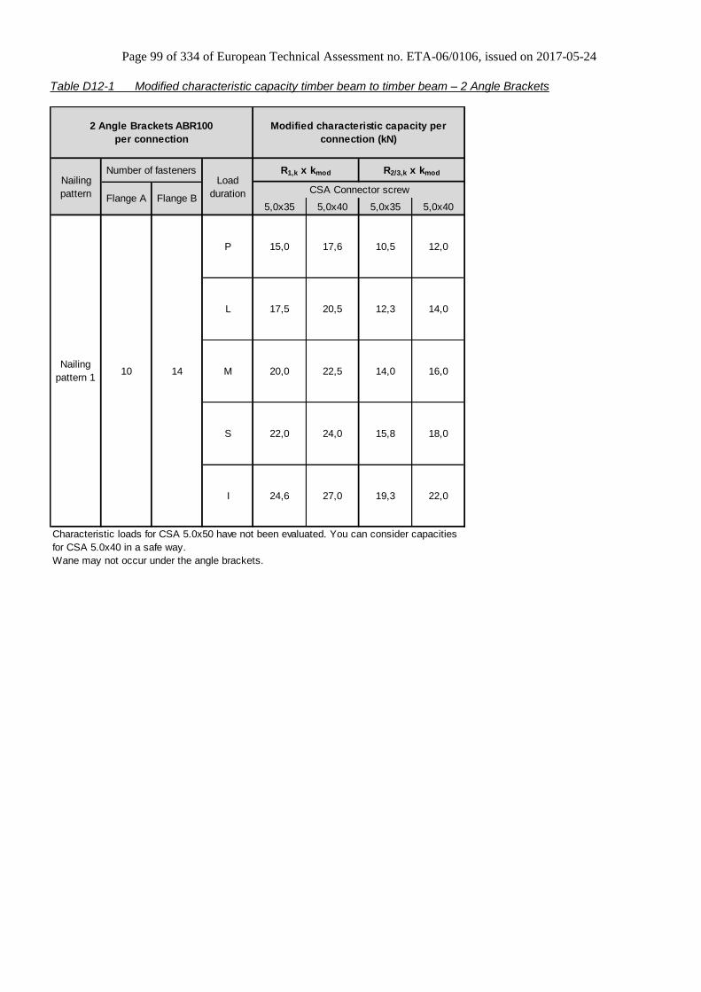
Page 99 of 334 of European Technical Assessment no. ETA-06/0106, issued on 2017-05-24
Table D12-1 Modified characteristic capacity timber beam to timber beam – 2 Angle Brackets
5,0x35 5,0x40 5,0x35 5,0x40
Wane may not occur under the angle brackets.
Modified characteristic capacity per
connection (kN)
24,6 27,0
22,5
22,0
Number of fasteners
Flange A Flange B
10
Nailing
pattern
Load
duration CSA Connector screw
R1,k x kmod
20,0
2 Angle Brackets ABR100
per connection
14
I
L
22,0
24,0
12,0
14,0
18,0
20,5
15,8
12,3
P 15,0 17,6
Characteristic loads for CSA 5.0x50 have not been evaluated. You can consider capacities
for CSA 5.0x40 in a safe way.
R2/3,k x kmod
10,5
16,0Nailing
pattern 1M
S
14,0
19,3
17,5

Page 100 of 334 of European Technical Assessment no. ETA-06/0106, issued on 2017-05-24
Table D12-2 Modified characteristic capacity timber beam to timber beam – 1 Angle Bracket
5,0x35 5,0x40 5,0x35 5,0x40
f ≤ 30 : f ≤ 21 :
239,8 277,3
f + 55,5 f + 55,5
21 < f ≤ 26 :
140,8
f + 18
f > 30 : f > 26 :
84,5 84,5
f f
f ≤ 21 : f ≤ 12 :
276,4 320,1
f + 55,5 f + 55,5
21 < f ≤ 26 : 12 < f ≤ 26 :
140,8 140,8
f + 18 f + 18
f > 26 : f > 26 :
84,5 84,5
f f
f ≤ 13 : f ≤ 6 :
313 363
f + 55,5 f + 55,5
13 < f ≤ 26 : 6 < f ≤ 26 :
140,8 140,8
f + 18 f + 18
f > 26 : f > 26 :
84,5 84,5
f f
f ≤ 8 : f ≤ 2 :
349,6 405,9
f + 55,5 f + 55,5
8 < f ≤ 26 : 2 < f ≤ 26 :
140,8 140,8
f + 18 f + 18
f > 26 : f > 26 :
84,5 84,5
f f
f ≤ 26 : f ≤ 26 :
140,8 140,8
f + 18 f + 18
f > 26 : f > 26 :
84,5 84,5
f f
Wane may not occur under the angle bracket.
Modified characteristic capacity per connection (kN)
L
1 Angle Bracket ABR100
per connection
R2/3,k x kmod
5,3
Number of fasteners
Flange A Flange B
10 14
6,1
P
Nailing
pattern
Load
duration CSA Connector screw
R1,k x kmod
Nailing
pattern 1
6,0
7
9,7 11
M
S
I
7,9
7,0 8
9
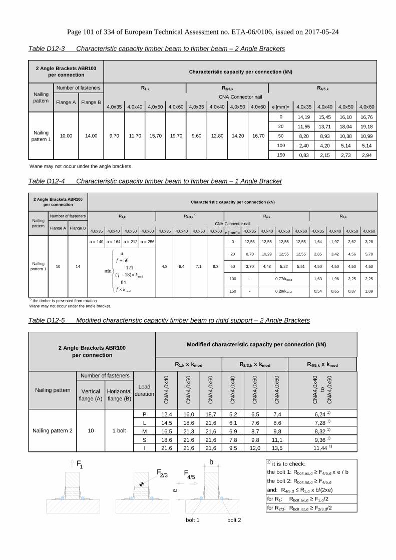
Page 101 of 334 of European Technical Assessment no. ETA-06/0106, issued on 2017-05-24
Table D12-3 Characteristic capacity timber beam to timber beam – 2 Angle Brackets
4,0x35 4,0x40 4,0x50 4,0x60 4,0x35 4,0x40 4,0x50 4,0x60 e [mm]= 4,0x35 4,0x40 4,0x50 4,0x60
0 14,19 15,45 16,10 16,76
20 11,55 13,71 18,04 19,18
50 8,20 8,93 10,38 10,99
100 2,40 4,20 5,14 5,14
150 0,83 2,15 2,73 2,94
Wane may not occur under the angle brackets.
2 Angle Brackets ABR100
per connection
10,00 14,00
R4/5,k
Characteristic capacity per connection (kN)
CNA Connector nail
Number of fasteners
Flange A Flange B
Nailing
pattern
Nailing
pattern 116,7014,2012,8019,7015,7011,70
R1,k
9,609,70
R2/3,k
Table D12-4 Characteristic capacity timber beam to timber beam – 1 Angle Bracket
4,0x35 4,0x40 4,0x50 4,0x60 4,0x35 4,0x40 4,0x50 4,0x60 e [mm]= 4,0x35 4,0x40 4,0x50 4,0x60 4,0x35 4,0x40 4,0x50 4,0x60
a = 140 a = 164 a = 212 a = 256 0 12,55 12,55 12,55 12,55 1,64 1,97 2,62 3,28
20 8,70 10,29 12,55 12,55 2,85 3,42 4,56 5,70
50 3,70 4,43 5,22 5,51 4,50 4,50 4,50 4,50
100 - 1,63 1,96 2,25 2,25
150 - 0,54 0,65 0,87 1,09
*) the timber is prevented from rotation
Wane may not occur under the angle bracket.
6,4 7,1 8,3
0,77/kmod
0,29/kmod
CNA Connector nail
Characteristic capacity per connection (kN)
R4,k R5,k
4,8
R2/3,k *)R1,kNumber of fasteners
Flange A Flange B
10 14
2 Angle Brackets ABR100
per connection
Nailing
pattern
Nailing
pattern 1
mod
mod
84
)18(
121
56
min
kf
kf
f
a
Table D12-5 Modified characteristic capacity timber beam to rigid support – 2 Angle Brackets
Vertical
flange (A)
Horizontal
flange (B)
P 12,4 16,0 18,7 5,2 6,5 7,4
L 14,5 18,6 21,6 6,1 7,6 8,6
M 16,5 21,3 21,6 6,9 8,7 9,8
S 18,6 21,6 21,6 7,8 9,8 11,1
I 21,6 21,6 21,6 9,5 12,0 13,5
1) it is to check:
the bolt 1: Rbolt,ax,d ≥ F4/5,d x e / b
the bolt 2: Rbolt,lat,d ≥ F4/5,d
and: R4/5,d ≤ R1,d x b/(2xe)
for R1: Rbolt,ax,d ≥ F1,d/2
for R2/3: Rbolt,lat,d ≥ F2/3,d/2
R2/3,k x kmod R4/5,k x kmod
Nailing pattern 2
CN
A4,0
x50
CN
A4,0
x60
6,24 1)
7,28 1)
8,32 1)
2 Angle Brackets ABR100
per connection
Nailing patternLoad
duration
CN
A4,0
x40
Modified characteristic capacity per connection (kN)
R1,k x kmod
CN
A4,0
x40
CN
A4,0
x50
CN
A4,0
x60
CN
A4,0
x40
to
CN
A4,0
x60
10 1 bolt
Number of fasteners
9,36 1)
11,44 1)
F 1
e
F4/5
b
F 2/3
bolt 1 bolt 2
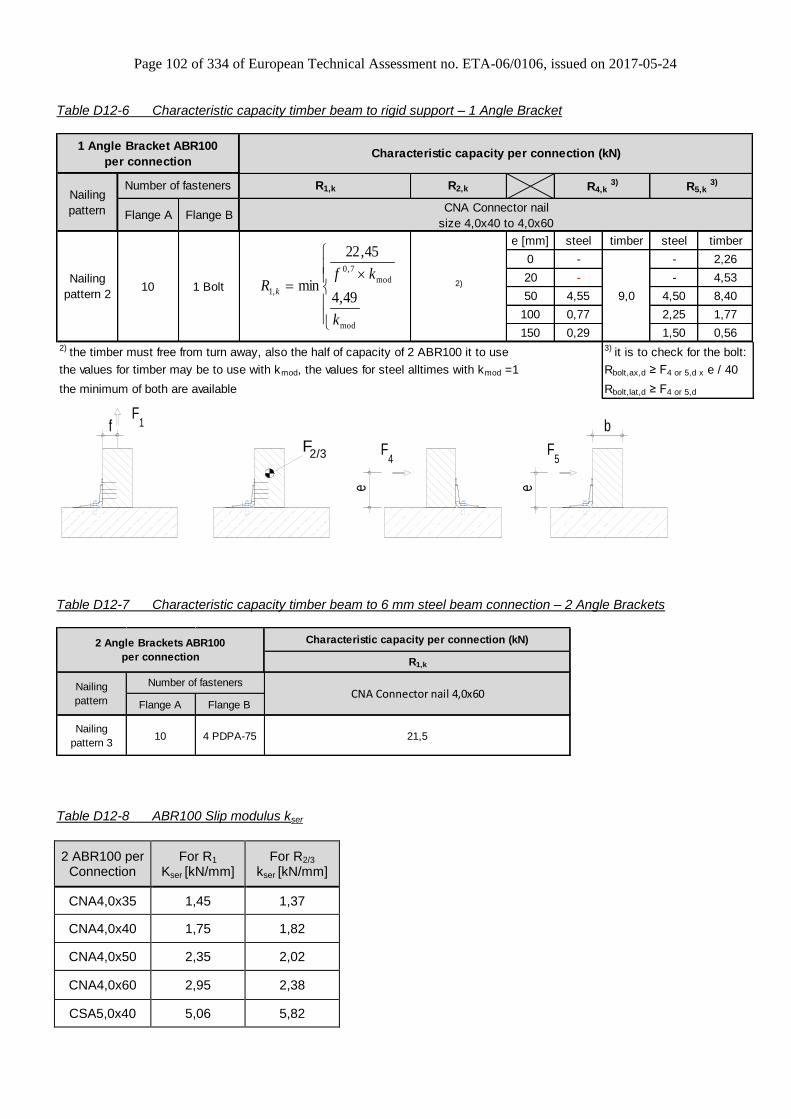
Page 102 of 334 of European Technical Assessment no. ETA-06/0106, issued on 2017-05-24
Table D12-6 Characteristic capacity timber beam to rigid support – 1 Angle Bracket
Flange A Flange B
e [mm] steel timber steel timber
0 - - 2,26
20 - - 4,53
50 4,55 4,50 8,40
100 0,77 2,25 1,77
150 0,29 1,50 0,562) the timber must free from turn away, also the half of capacity of 2 ABR100 it to use 3) it is to check for the bolt:
the values for timber may be to use with kmod, the values for steel alltimes with kmod =1 Rbolt,ax,d ≥ F4 or 5,d x e / 40
the minimum of both are available Rbolt,lat,d ≥ F4 or 5,d
1 Angle Bracket ABR100
per connection
Nailing
pattern
Number of fasteners
10 1 BoltNailing
pattern 2 9,02)
Characteristic capacity per connection (kN)
CNA Connector nail
size 4,0x40 to 4,0x60
R1,k R2,k R4,k 3) R5,k
3)
mod
mod
7,0
,149,4
45,22
min
k
kfR k
F4
e
F5
e
bfF
1
F 2/3
Table D12-7 Characteristic capacity timber beam to 6 mm steel beam connection – 2 Angle Brackets
Characteristic capacity per connection (kN)
R1,k
Flange A Flange B
Nailing
pattern 310 4 PDPA-75 21,5
2 Angle Brackets ABR100
per connection
Nailing
pattern
Number of fastenersCNA Connector nail 4,0x60
Table D12-8 ABR100 Slip modulus kser
2 ABR100 per Connection
For R1 Kser [kN/mm]
For R2/3 kser [kN/mm]
CNA4,0x35 1,45 1,37
CNA4,0x40 1,75 1,82
CNA4,0x50 2,35 2,02
CNA4,0x60 2,95 2,38
CSA5,0x40 5,06 5,82
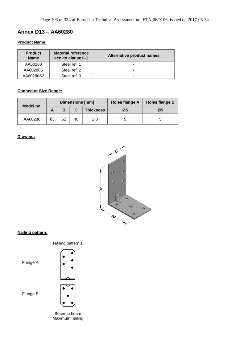
Page 103 of 334 of European Technical Assessment no. ETA-06/0106, issued on 2017-05-24
Annex D13 – AA60280
Product Name:
Product
Name
Material reference
acc. to clause II-1 Alternative product names
AA60280 Steel ref. 1 -
AA60280S Steel ref. 2 -
AA60280S2 Steel ref. 3 -
Connector Size Range:
Model no. Dimensions [mm] Holes flange A Holes flange B
A B C Thickness Ø5 Ø5
AA60280 83 62 40 2,0 5 5
Drawing:
Nailing pattern:
Nailing pattern 1
Flange A:
Flange B:
Beam to beam
Maximum nailing
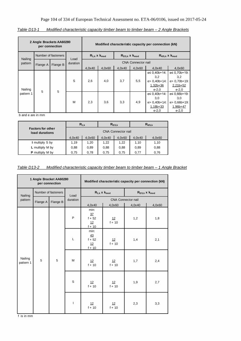
Page 104 of 334 of European Technical Assessment no. ETA-06/0106, issued on 2017-05-24
Table D13-1 Modified characteristic capacity timber beam to timber beam – 2 Angle Brackets
4,0x40 4,0x60 4,0x40 4,0x60 4,0x40 4,0x60
e≤ 0,40b+14: e≤ 0,70b+19:
3,2 3,2
e> 0,40b+14: e> 0,70b+19:
1,32b+36 2,21b+52
e-2,0 e-2,0
e≤ 0,40b+14: e≤ 0,66b+19:
3,0 3,0
e> 0,40b+14: e> 0,66b+19:
1,18b+33 1,96b+47
e-2,0 e-2,0
b and e are in mm
4,0x40 4,0x60 4,0x40 4,0x60 4,0x40 4,0x60
1,19 1,20 1,22 1,22 1,10 1,10
0,88 0,89 0,88 0,88 0,89 0,88
0,75 0,78 0,75 0,75 0,77 0,76
Modified characteristic capacity per connection (kN)
R1,k x kmod R2/3,k x kmod R4/5,k x kmod
Load
duration
2 Angle Brackets AA60280
per connection
CNA Connector nailNailing
pattern
Number of fasteners
Flange A
5,52,6 4,0 3,7S
4,9
CNA Connector nail
R1,k R2/3,k R4/5,k
M 2,3 3,6 3,3
P multiply M by
Flange B
5 5
Factors for other
load durations
I multiply S by
L multiply M by
Nailing
pattern 1
Table D13-2 Modified characteristic capacity timber beam to timber beam – 1 Angle Bracket
4,0x40 4,0x60 4,0x40 4,0x60
min:
37
f + 52 12 1,2 1,8
12 f + 10
f + 10
min:
43
f + 52 12 1,4 2,1
12 f + 10
f + 10
12 12 1,7 2,4
f + 10 f + 10
12 12 1,9 2,7
f + 10 f + 10
12 12 2,3 3,3
f + 10 f + 10
f is in mm
5 5
1 Angle Bracket AA60280
per connection
Nailing
pattern
Load
duration
Number of fasteners
Flange A Flange B
Modified characteristic capacity per connection (kN)
R1,k x kmod R2/3,k x kmod
S
CNA Connector nail
Nailing
pattern 1
I
P
L
M

Page 105 of 334 of European Technical Assessment no. ETA-06/0106, issued on 2017-05-24
Annex D14 – ABB40390
Product Name:
Product
Name
Material reference
acc. to clause II-1 Alternative product names
ABB40390 Steel ref. 1 -
ABB40390S Steel ref. 2 -
ABB40390S2 Steel ref. 3 -
Connector Size Range:
Model no. Dimensions [mm] Holes flange A Holes flange B
A B C Thickness Ø5 Ø5
AA60280 93 93 40 3,0 5 5
Drawing:
Nailing pattern:
Nailing pattern 1 Nailing pattern 2
Flange A:
Flange B:
Beam to beam
Maximum nailing Beam to beam
Minimum nailing

Page 106 of 334 of European Technical Assessment no. ETA-06/0106, issued on 2017-05-24
Table D14-1 Modified characteristic capacity timber beam to timber beam – 2 Angle Brackets
4,0x40 4,0x60 4,0x40 4,0x60 4,0x40 4,0x60
e≤ 0,21b+14: e≤ 0,30b+15:
4,5 4,6
e> 0,21b+14: e> 0,30b+15:
0,96b+48 1,38b+57
e-3,0 e-3,0
e≤ 0,24b+16: e≤ 0,29b+16:
3,6 4,3
e> 0,24b+16: e> 0,29b+16:
0,88b+46 1,26b+54
e-3,0 e-3,0
e≤ 0,32b+16: e≤ 0,49b+19:
4,5 4,6
e> 0,32b+16: e> 0,49b+19:
1,46b+59 2,22b+75
e-3,0 e-3,0
e≤ 0,37b+18: e≤ 0,47b+19:
3,6 4,3
e> 0,37b+18: e> 0,47b+19:
1,34b+56 2,01b+71
e-3,0 e-3,0
b and e are in mm
4,0x40 4,0x60 4,0x40 4,0x60 4,0x40 4,0x60
1,15 1,00 1,22 1,22 1,10 1,06
0,88 0,88 0,88 0,88 0,84 0,90
0,75 0,75 0,75 0,75 0,78 0,80
R1,k R2/3,k R4/5,k
CNA Connector nail
2,7 4,4
3,9 1,6
2 Angle Brackets ABB40390
per connection
Nailing
pattern CNA Connector nail
Nailing
pattern 2
Nailing
pattern 1
2,5 1,4
2,5
M 2,4
S
1,5S
1,8
1,8M 1,8
5
Modified characteristic capacity per connection (kN)
R1,k x kmod R2/3,k x kmod R4/5,k x kmodLoad
duration
2,01,9 2,8
2,2
Factors for other
load durations
I multiply S by
L multiply M by
P multiply M by
Number of fasteners
Flange A Flange B
3 3
3
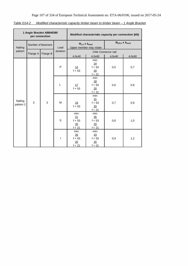
Page 107 of 334 of European Technical Assessment no. ETA-06/0106, issued on 2017-05-24
Table D14-2 Modified characteristic capacity timber beam to timber beam – 1 Angle Bracket
4,0x40 4,0x60 4,0x40 4,0x60
min:
24
14 f + 53 0,5 0,7
f + 53 20
f + 21
min:
28
17 f + 53 0,6 0,8
f + 53 20
f + 21
min:
31
19 f + 53 0,7 0,9
f + 53 20
f + 21
min: min:
21 35
f + 53 f + 53 0,8 1,0
20 20
f + 21 f + 21
min: min:
26 43
f + 53 f + 53 0,9 1,2
20 20
f + 21 f + 21
P
L
M
Number of fasteners
Flange A Flange B
3 3
1 Angle Bracket ABB40390
per connection
Nailing
pattern
Nailing
pattern 2
CNA Connector nail
I
S
Load
duration
Modified characteristic capacity per connection (kN)
R1,k x kmod
Upper member may rotate
R2/3,k x kmod

Page 108 of 334 of European Technical Assessment no. ETA-06/0106, issued on 2017-05-24
Table D14-3 Modified characteristic capacity timber beam to timber beam – 1 Angle Bracket
4,0x40 4,0x60 4,0x40 4,0x60
min:
28
f + 53 20 0,6 0,8
20 f + 21
f + 21
min:
33
f + 53 20 0,7 1,0
20 f + 21
f + 21
20 20 0,8 1,1
f + 21 f + 21
20 20 0,9 1,2
f + 21 f + 21
20 20 1,1 1,5
f + 21 f + 21
3 5
Modified characteristic capacity per connection (kN)
Load
duration
R1,k x kmod R2/3,k x kmod
P
CNA Connector nail
L
M
S
I
1 Angle Bracket ABB40390
per connection
Nailing
pattern
Nailing
pattern 1
Number of fasteners
Flange A Flange B

Page 109 of 334 of European Technical Assessment no. ETA-06/0106, issued on 2017-05-24
Annex D15 – AE48
Product Name:
Product
Name
Material reference
acc. to clause II-1 Alternative product names
AE48 Steel ref. 1 France: EB/7048
AE48S Steel ref. 2 -
AE48S2 Steel ref. 3 -
Connector Size Range:
Model no. Dimensions [mm] Holes flange A Holes flange B
A B C Thickness Ø5 Ø13 Ø5 Ø13
AE48 90 48 48 3,0 7 2 4 1
Drawing:
Nailing pattern:
Nailing pattern 1 Nailing pattern 2 Nailing pattern 3 Nailing pattern 4 Nailing pattern 5
Flange A:
Flange B:
Nailing
pattern
No of fasteners Description
Flange A Flange B
1 6 4 Max. nailing with force F1 , F2, F3, F4 and F5
2 7 4 Max. nailing with force F2 and F3
3 4 4 Min. nailing with force F1 , F2, F3, F4 and F5
4 6 1 x M12 Max. nailing with force F1 , F2, F3, F4 and F5
5 7 1 x M12 Max. nailing with force F2 and F3
Square washer (US40/40/10G or US40/50/10G) can be replaced by standard washer of the bolts (bolt Ø12 – washer Ø24). In this case, the value of klat and kax must be adapted (see tables below D15-4 and D15-5).

Page 110 of 334 of European Technical Assessment no. ETA-06/0106, issued on 2017-05-24
Table D15-1 Modified characteristic capacity timber beam to timber beam – 2 Angle Brackets
4.0x40 4.0x60 4.0x40 4.0x60 4.0x40 4.0x60
3,39 3,39
0.88b+38 1.47b+42
e-3 e-3
3,66 3,66
1.03b+39 1.72b+44
e-3 e-3
3,91 4,04
1.18b+40 1.96b+46
e-3 e-3
4,15 5,29
1.32b+41 2.21b+47
e-3 e-3
5,36 5,85
1.62b+43 2.70b+51
e-3 e-3
3,39 3,39
0.88b+38 1.47b+42
e-3 e-3
3,66 3,66
1.03b+39 1.72b+44
e-3 e-3
3,91 4,04
1.18b+40 1.96b+46
e-3 e-3
4,15 5,29
1.32b+41 2.21b+47
e-3 e-3
5,36 5,85
1.62b+43 2.70b+51
e-3 e-3
4 4
Number of fasteners
Flange A Flange B
S 2,6 4,4 3,6 4,9
I 3,2 5,4 4,3 6
2,8 3,8
M 2,4 3,9 3,2 4,4
-
Nailing
Pattern 3
P 1,8 2,9 2,4 3,3
L 2,1 3,4
I - - 4,5 6,8 -
4,9 - -
S - - 3,6 5,5 - -
- -
L - - 2,8 4,3 - -
3,7
Nailing
Pattern 2
P - - 2,4
M - - 3,27 4
4,8
I 3,2 5,4 4,4 6,6
S 2,6 4,4 3,6 5,4
Nailing
pattern 1
P 1,8 2,9 2,4
M 2,4 3,9 3,26 4
3,6
L 2,1 3,4 2,8 4,2
2 Angle Brackets AE48 per connection Modified characteristic capacity per connection (kN)
Nailing
pattern
Load
duration
R1,k x kmod R2/3,k x kmod
R4/5,k x kmod (Minimum
between values)
CNA Connector nail
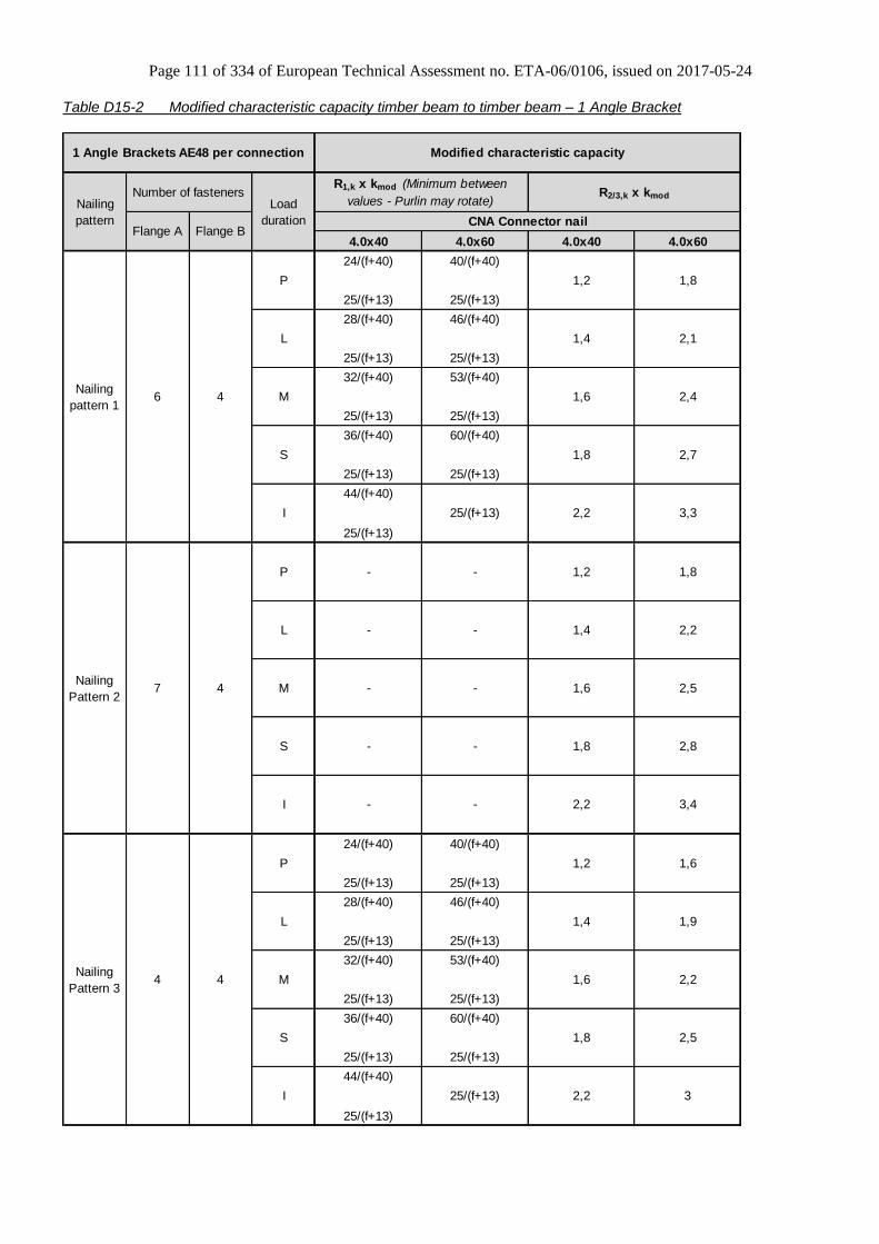
Page 111 of 334 of European Technical Assessment no. ETA-06/0106, issued on 2017-05-24
Table D15-2 Modified characteristic capacity timber beam to timber beam – 1 Angle Bracket
4.0x40 4.0x60 4.0x40 4.0x60
24/(f+40) 40/(f+40)
25/(f+13) 25/(f+13)
28/(f+40) 46/(f+40)
25/(f+13) 25/(f+13)
32/(f+40) 53/(f+40)
25/(f+13) 25/(f+13)
36/(f+40) 60/(f+40)
25/(f+13) 25/(f+13)
44/(f+40)
25/(f+13)
25/(f+13)
24/(f+40) 40/(f+40)
25/(f+13) 25/(f+13)
28/(f+40) 46/(f+40)
25/(f+13) 25/(f+13)
32/(f+40) 53/(f+40)
25/(f+13) 25/(f+13)
36/(f+40) 60/(f+40)
25/(f+13) 25/(f+13)
44/(f+40)
25/(f+13)
25/(f+13)
6 4
7 4
4 4Nailing
Pattern 3
P 1,2 1,6
L 1,4 1,9
M 1,6 2,2
S 1,8 2,5
I 2,2 3
2,5
I - - 2,2 3,4
S - - 1,8 2,8
Nailing
Pattern 2
P - - 1,2
M - - 1,6
1,8
L - - 1,4 2,2
Nailing
pattern 1
P 1,2 1,8
L 1,4 2,1
M 1,6 2,4
S 1,8 2,7
I 2,2 3,3
1 Angle Brackets AE48 per connection Modified characteristic capacity
Nailing
pattern
Load
duration
R1,k x kmod (Minimum between
values - Purlin may rotate)R2/3,k x kmod
CNA Connector nail
Number of fasteners
Flange A Flange B
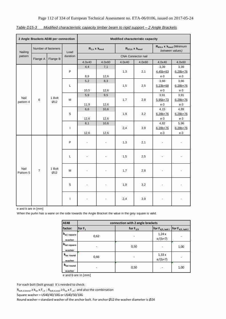
Page 112 of 334 of European Technical Assessment no. ETA-06/0106, issued on 2017-05-24
Table D15-3 Modified characteristic capacity timber beam to rigid support – 2 Angle Brackets
4.0x40 4.0x60 4.0x40 4.0x60 4.0x40 4.0x60
4,4 7,1 3,39 3,39
4.45b+63 6.28b+76
8,9 12,6 e-3 e-3
5,2 8,3 3,66 3,66
5.23b+68 6.28b+76
10,5 12,6 e-3 e-3
5,9 9,5 3,91 3,91
5.95b+73 6.28b+76
11,9 12,6 e-3 e-3
6,6 10,6 4,15 4,89
6.28b+76 6.28b+76
12,6 12,6 e-3 e-3
8,1 10,6 4,82 5,96
6.28b+76 6.28b+76
12,6 12,6 e-3 e-3
AE48
factor: for F4/5, bolt 1 for F4/5, bolt 2
kax square
washer
1,24 x
e/(b+7) -
klat square
washer
- 1,00
kax round
washer
1,33 x
e/(b+7) -
klat round
washer
- 1,00
e and b are in [mm]
For each bolt (bolt group) it´s needed to check:
Rbolt,d,lateral ≥ klat x Fi,d ; Rbolt,d,axial ≥ kax x Fi,d ; and also the combination
Square washer = US40/40/10G or US40/50/10G
Round washer = standard washer of the anchor bolt. For anchor Ø12 the washer diameter is Ø24
-
connection with 2 angle brackets
for F2/3
-
0,50
-
0,50
-
for F1
0,62
-
0,66
e and b are in [mm]
When the purlin has a wane on the side towards the Angle Bracket the value in the grey square is valid.
I - - 2,4 3,9 -
Nail
Pattern 52,8 - -
S - - 1,9 3,2 - -
M - - 1,7
2,4 3,9
- -
L - - 1,5 2,5 - -
P - - 1,3 2,1
1,7 2,8
S 1,9 3,2
1,3 2,1
L 1,5 2,5
Modified characteristic capacity
Nailing
pattern
Load
duration
R1,k x kmod R2/3,k x kmod
R4/5,k x kmod (Minimum
between values)
CNA Connector nail
Number of fasteners
Flange A Flange B
61 Bolt
Ø12
71 Bolt
Ø12
2 Angle Brackets AE48 per connection
Nail
pattern 4
P
M
I
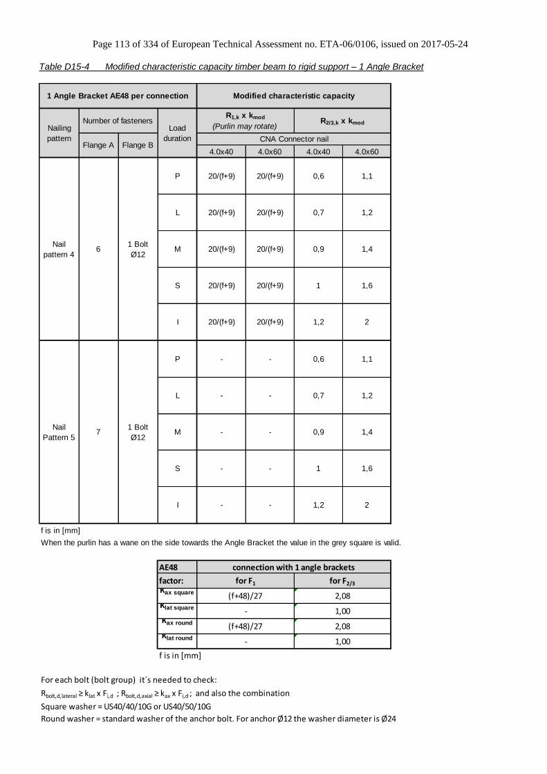
Page 113 of 334 of European Technical Assessment no. ETA-06/0106, issued on 2017-05-24
Table D15-4 Modified characteristic capacity timber beam to rigid support – 1 Angle Bracket
4.0x40 4.0x60 4.0x40 4.0x60
AE48
factor:kax square
washerklat square
washerkax round
washerklat round
washerf is in [mm]
For each bolt (bolt group) it´s needed to check:
Rbolt,d,lateral ≥ klat x Fi,d ; Rbolt,d,axial ≥ kax x Fi,d ; and also the combination
Square washer = US40/40/10G or US40/50/10G
Round washer = standard washer of the anchor bolt. For anchor Ø12 the washer diameter is Ø24
(f+48)/27 2,08
- 1,00
f is in [mm]
When the purlin has a wane on the side towards the Angle Bracket the value in the grey square is valid.
connection with 1 angle brackets
for F1 for F2/3
(f+48)/27 2,08
- 1,00
1,4
I - - 1,2 2
S - - 1 1,6
Nail
Pattern 5
P - - 0,6
M - - 0,971 Bolt
Ø12
1,1
L - - 0,7 1,2
1,4
I 20/(f+9) 20/(f+9) 1,2 2
S 20/(f+9) 20/(f+9) 1 1,6
Nail
pattern 4
P 20/(f+9) 20/(f+9) 0,6
M 20/(f+9) 20/(f+9) 0,961 Bolt
Ø12
1,1
L 20/(f+9) 20/(f+9) 0,7 1,2
1 Angle Bracket AE48 per connection Modified characteristic capacity
Nailing
pattern
Load
duration
R1,k x kmod
(Purlin may rotate)R2/3,k x kmod
CNA Connector nail
Number of fasteners
Flange A Flange B
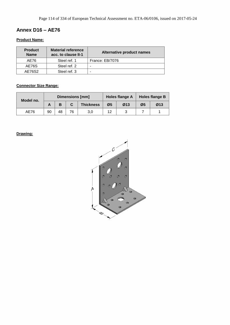
Page 114 of 334 of European Technical Assessment no. ETA-06/0106, issued on 2017-05-24
Annex D16 – AE76
Product Name:
Product
Name
Material reference
acc. to clause II-1 Alternative product names
AE76 Steel ref. 1 France: EB/7076
AE76S Steel ref. 2 -
AE76S2 Steel ref. 3 -
Connector Size Range:
Model no. Dimensions [mm] Holes flange A Holes flange B
A B C Thickness Ø5 Ø13 Ø5 Ø13
AE76 90 48 76 3,0 12 3 7 1
Drawing:
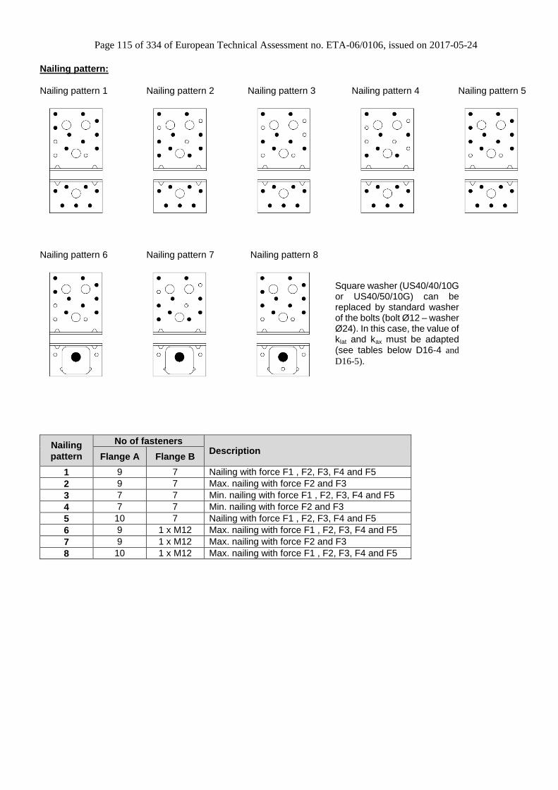
Page 115 of 334 of European Technical Assessment no. ETA-06/0106, issued on 2017-05-24
Nailing pattern:
Nailing pattern 1 Nailing pattern 2 Nailing pattern 3 Nailing pattern 4 Nailing pattern 5
Nailing pattern 6 Nailing pattern 7 Nailing pattern 8
Nailing
pattern
No of fasteners Description
Flange A Flange B
1 9 7 Nailing with force F1 , F2, F3, F4 and F5
2 9 7 Max. nailing with force F2 and F3
3 7 7 Min. nailing with force F1 , F2, F3, F4 and F5
4 7 7 Min. nailing with force F2 and F3
5 10 7 Nailing with force F1 , F2, F3, F4 and F5
6 9 1 x M12 Max. nailing with force F1 , F2, F3, F4 and F5
7 9 1 x M12 Max. nailing with force F2 and F3
8 10 1 x M12 Max. nailing with force F1 , F2, F3, F4 and F5
Square washer (US40/40/10G or US40/50/10G) can be replaced by standard washer of the bolts (bolt Ø12 – washer Ø24). In this case, the value of klat and kax must be adapted (see tables below D16-4 and
D16-5).

Page 116 of 334 of European Technical Assessment no. ETA-06/0106, issued on 2017-05-24
Table D16-1 Modified characteristic capacity timber beam to timber beam – 2 Angle Brackets
4.0x40 4.0x60 4.0x40 4.0x60 4.0x40 4.0x60
7 7
1.76b+98 2.94b+107
e-3 e-3
7,56 7,56
2.06b+100 3.43b+110
e-3 e-3
8,09 8,09
2.35b+102 3.92b+113
e-3 e-3
8,58 8,58
2.65b+105 4.41b+117
e-3 e-3
9,48 11,25
3.24b+109 5.39b+124
e-3 e-3
7 7
1.76b+98 2.94b+107
e-3 e-3
7,56 7,56
2.06b+100 3.43b+110
e-3 e-3
8,09 8,09
2.35b+102 3.92b+113
e-3 e-3
8,58 8,58
2.65b+105 4.41b+117
e-3 e-3
9,48 9,48
3.24b+109 5.39b+124
e-3 e-3
7 7
1.76b+98 2.94b+107
e-3 e-3
7,56 7,56
2.06b+100 3.43b+110
e-3 e-3
8,09 8,09
2.35b+102 3.92b+113
e-3 e-3
8,58 8,58
2.65b+105 4.41b+117
e-3 e-3
9,48 11,25
3.24b+109 5.39b+124
e-3 e-3
b and e are in [mm]
9 7
7 7
7 7
10 3
2 Angle Brackets AE76 per connection Modified characteristic capacity (kN)
Nailing
pattern
Load
duration
R1,k x kmod R2/3,k x kmod
R4/5,k x kmod (Minimum
between values)
CNA Connector nail
11
Number of fasteners
Flange A Flange B
9 7 M 4,7 7,8 9,3 12,5Nailing
pattern 1
P 3,5 5,9 7 9,4
L 4,1 6,9 8,1
S 5,3 8,8 10,4 14,1
I 6,5 10,8 12,8 17,2
- -
L - - 8,4 12,2 - -
P - - 7,2 10,4
13,9 - -
S - - 10,8 15,6 - -
M - - 9,6
6,7 9,2
M 4,7 7,8 7,6 10,5
-
Nailing
Pattern 3
P 3,5 5,9 5,7 7,9
L 4,1 6,9
I - - 13,2 19,1 -
Nailing
Pattern 2
S 5,3 8,8 8,6 11,8
I 6,5 10,8 10,5 14,5
- -
L - - 7,3 10 - -
P - - 6,3 8,6
11,4 - -
S - - 9,4 12,9 - -
M - - 8,4
7,3 10,1
4,12 8,5 11,8
-
Nailing
Pattern 5
P
L
M
S
I
3,53
I - - 11,5 15,7 -
Nailing
Pattern 4
6,5 13,4 18,5
5,3 10,9 15,1
4,7 9,7 13,4
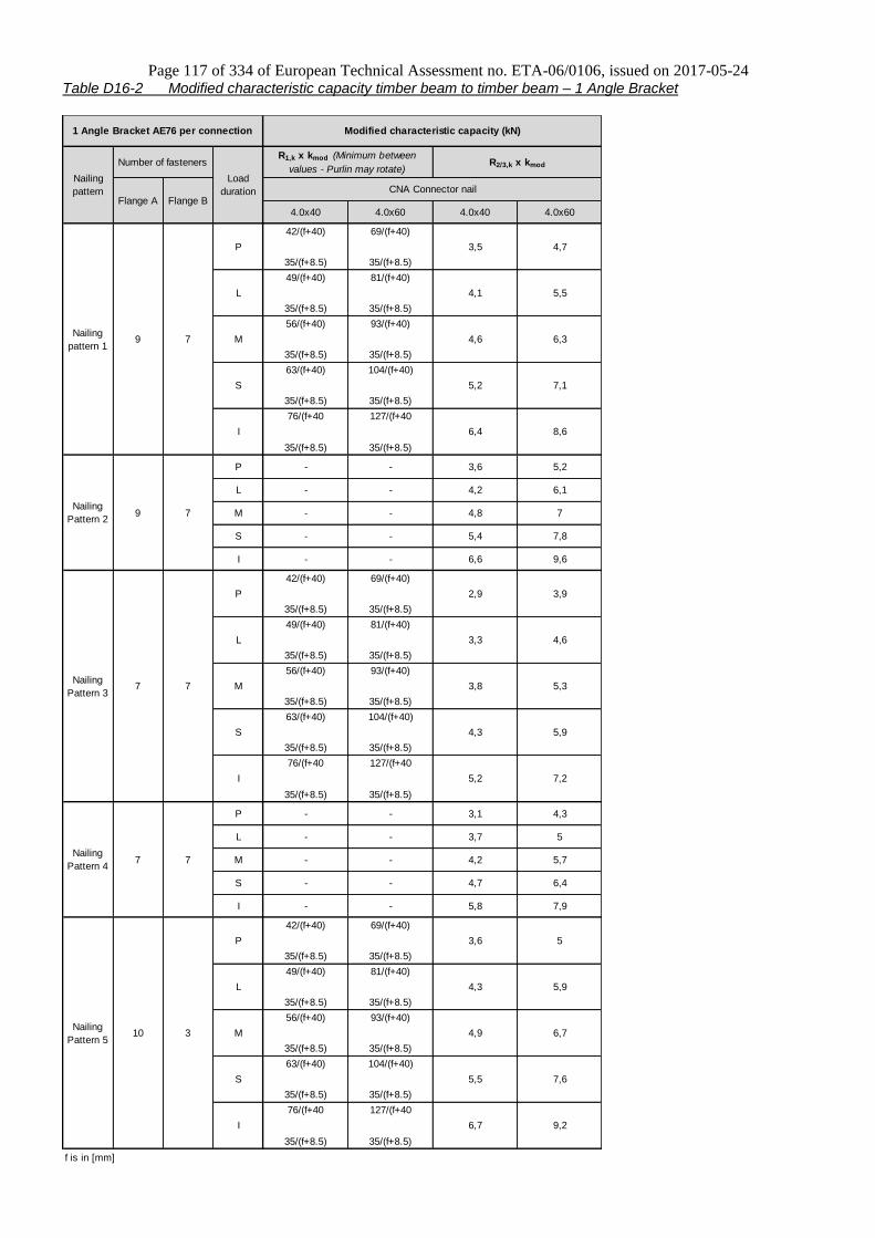
Page 117 of 334 of European Technical Assessment no. ETA-06/0106, issued on 2017-05-24
Table D16-2 Modified characteristic capacity timber beam to timber beam – 1 Angle Bracket
4.0x40 4.0x60 4.0x40 4.0x60
42/(f+40) 69/(f+40)
35/(f+8.5) 35/(f+8.5)
49/(f+40) 81/(f+40)
35/(f+8.5) 35/(f+8.5)
56/(f+40) 93/(f+40)
35/(f+8.5) 35/(f+8.5)
63/(f+40) 104/(f+40)
35/(f+8.5) 35/(f+8.5)
76/(f+40 127/(f+40
35/(f+8.5) 35/(f+8.5)
42/(f+40) 69/(f+40)
35/(f+8.5) 35/(f+8.5)
49/(f+40) 81/(f+40)
35/(f+8.5) 35/(f+8.5)
56/(f+40) 93/(f+40)
35/(f+8.5) 35/(f+8.5)
63/(f+40) 104/(f+40)
35/(f+8.5) 35/(f+8.5)
76/(f+40 127/(f+40
35/(f+8.5) 35/(f+8.5)
42/(f+40) 69/(f+40)
35/(f+8.5) 35/(f+8.5)
49/(f+40) 81/(f+40)
35/(f+8.5) 35/(f+8.5)
56/(f+40) 93/(f+40)
35/(f+8.5) 35/(f+8.5)
63/(f+40) 104/(f+40)
35/(f+8.5) 35/(f+8.5)
76/(f+40 127/(f+40
35/(f+8.5) 35/(f+8.5)
f is in [mm]
7 7
10 3
1 Angle Bracket AE76 per connection Modified characteristic capacity (kN)
Nailing
pattern
Load
duration
R1,k x kmod (Minimum between
values - Purlin may rotate)R2/3,k x kmod
CNA Connector nail
S 5,2 7,1
Number of fasteners
Flange A Flange B
9 7
I 6,4 8,6
Nailing
pattern 1
P 3,5 4,7
L 4,1 5,5
M 4,6 6,3
6,1
M - - 4,8 7Nailing
Pattern 2
P - - 3,6 5,2
L - - 4,2
S - - 5,4 7,8
I - - 6,6 9,6
S 4,3 5,9
I 5,2 7,2
Nailing
Pattern 3
P 2,9 3,9
L 3,3 4,6
M 3,8 5,3
9 7
7 7
5
M - - 4,2 5,7Nailing
Pattern 4
P - - 3,1 4,3
L - - 3,7
S - - 4,7 6,4
I - - 5,8 7,9
5,9
4,9 6,7
5,5 7,6
6,7 9,2
Nailing
Pattern 5
P
L
M
S
I
3,6 5
4,3

Page 118 of 334 of European Technical Assessment no. ETA-06/0106, issued on 2017-05-24
Table D16-3 Modified characteristic capacity timber beam to rigid support – 2 Angle Brackets
4.0x40 4.0x60 4.0x40 4.0x60 4.0x40 4.0x60
4,8 7,9 7 7
6.81b+134 8.41b+145
13,6 16,8 e-3 e-3
5,7 9,2 7,56 7,56
7.99b+142 8.41b+145
16,0 16,8 e-3 e-3
6,4 10,5 8,09 8,09
8.41b+145 8.41b+145
16,8 16,8 e-3 e-3
7,2 11,7 8,58 8,58
8.41b+145 8.41b+145
16,8 16,8 e-3 e-3
8,8 14,4 9,48 9,48
8.41b+145 8.41b+145
16,8 16,8 e-3 e-3
4,8 7,9 7 7
6.81b+134 8.41b+145
13,6 16,8 e-3 e-3
5,7 9,2 7,56 7,56
7.99b+142 8.41b+145
16,0 16,8 e-3 e-3
6,4 10,5 8,09 8,09
8.41b+145 8.41b+145
16,8 16,8 e-3 e-3
7,2 11,7 8,58 8,58
8.41b+145 8.41b+145
16,8 16,8 e-3 e-3
8,8 14,4 9,48 9,48
8.41b+145 8.41b+145
16,8 16,8 e-3 e-3
AE76
factor: for F4/5, bolt 1 for F4/5, bolt 2
kax square
washer
1,08 x
e/(b+7) -
klat square
washer
- 1,00
kax round
washer
1,16 x
e/(b+7) -
klat round
washer
- 1,00
e and b are in [mm]
For each bolt (bolt group) it´s needed to check:
Rbolt,d,lateral ≥ klat x Fi,d ; Rbolt,d,axial ≥ kax x Fi,d ; and also the combination
Square washer = US40/40/10G or US40/50/10G
Round washer = standard washer of the anchor bolt. For anchor Ø12 the washer diameter is Ø24
91 Bolt
Ø12
91 Bolt
Ø12
101 Bolt
Ø12
2 Angle Brackets AE76 per connection Modified characteristic capacity (kN)
Nailing
pattern
Load
duration
R1,k x kmod R2/3,k x kmod
R4/5,k x kmod (Minimum
between values)
CNA Connector nail
Number of fasteners
Flange A Flange B
Nailing
pattern 6
P 4,5 6,7
L 5,3 7,8
M 6,1 8,9
S 6,8 10
I 8,3 12,3
Nailing
Pattern 7
P - - 4,6
M - - 6,1
- -
L - - 5,3 8,2 - -
7,1
-
9,4 - -
S - - 6,9 10,6 - -
M 6,1 10,2
-
Nailing
Pattern 8
P 4,6 7,6
L 5,3 8,9
I - - 8,4 12,9
0,54 -
S 6,9 11,5
I 8,4 14
e and b are in [mm]
When the purlin has a wane on the side towards the Angle Bracket the value in the grey square is valid.
Connection with 2 Angle Brackets
for F1 for F2/3
- 0,5
0,58 -
- 0,5

Page 119 of 334 of European Technical Assessment no. ETA-06/0106, issued on 2017-05-24
Table D16-4 Modified characteristic capacity timber beam to rigid support – 1 Angle Bracket
4.0x40 4.0x60 4.0x40 4.0x60
f is in [mm]
AE76
factor:
kax square
washer
klat square
washer
kax round
washer
klat round
washer
f is in [mm]
For each bolt (bolt group) it´s needed to check:
Rbolt,d,lateral ≥ klat x Fi,d ; Rbolt,d,axial ≥ kax x Fi,d ; and also the combination
Square washer = US40/40/10G or US40/50/10G
Round washer = standard washer of the anchor bolt. For anchor Ø12 the washer diameter is Ø24
1 Angle Bracket AE76 per connection Modified characteristic capacity (kN)
Nailing
pattern
Load
duration
R1,k x kmod
(Purlin may rotate)R2/3,k x kmod
CNA Connector nail
Number of fasteners
Flange A Flange B
3,3
L 34/(f+5) 34/(f+5) 2,7 3,9
Nailing
pattern 6
P 34/(f+5) 34/(f+5) 2,3
M 34/(f+5) 34/(f+5) 391 Bolt
Ø124,5
I 34/(f+5) 34/(f+5) 4,2 6,1
S 34/(f+5) 34/(f+5) 3,4 5
3,5
L - - 2,7 4,1
Nailing
Pattern 7
P - - 2,3
M - - 391 Bolt
Ø124,7
I - - 4,2 6,5
S - - 3,4 5,3
3,8
L 34/(f+5) 34/(f+5) 2,7 4,5
Nailing
Pattern 8
P 34/(f+5) 34/(f+5) 2,3
M 34/(f+5) 34/(f+5) 3101 Bolt
Ø125,1
I 34/(f+5) 34/(f+5) 4,2 7
S 34/(f+5) 34/(f+5) 3,4 5,7
(f+45)/28 0,74
- 1
Connection with 1 Angle Bracket
(f+45)/28 0,74
for F2/3for F1
1 -
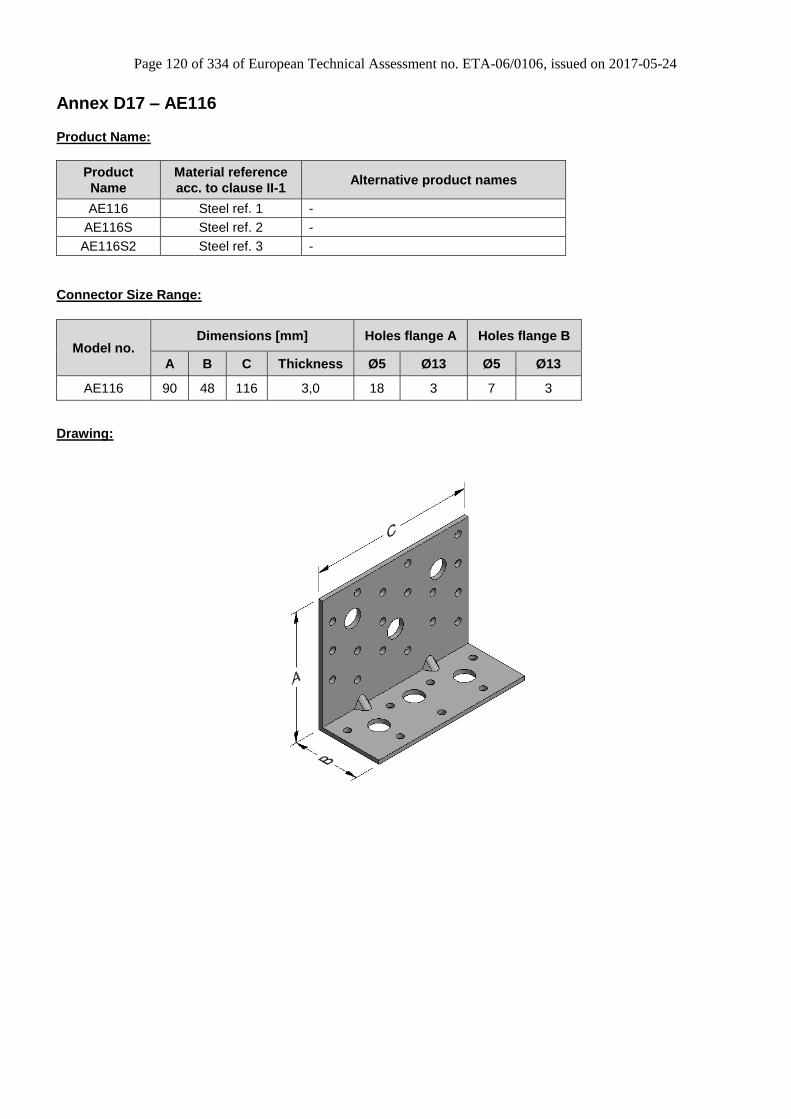
Page 120 of 334 of European Technical Assessment no. ETA-06/0106, issued on 2017-05-24
Annex D17 – AE116
Product Name:
Product
Name
Material reference
acc. to clause II-1 Alternative product names
AE116 Steel ref. 1 -
AE116S Steel ref. 2 -
AE116S2 Steel ref. 3 -
Connector Size Range:
Model no. Dimensions [mm] Holes flange A Holes flange B
A B C Thickness Ø5 Ø13 Ø5 Ø13
AE116 90 48 116 3,0 18 3 7 3
Drawing:
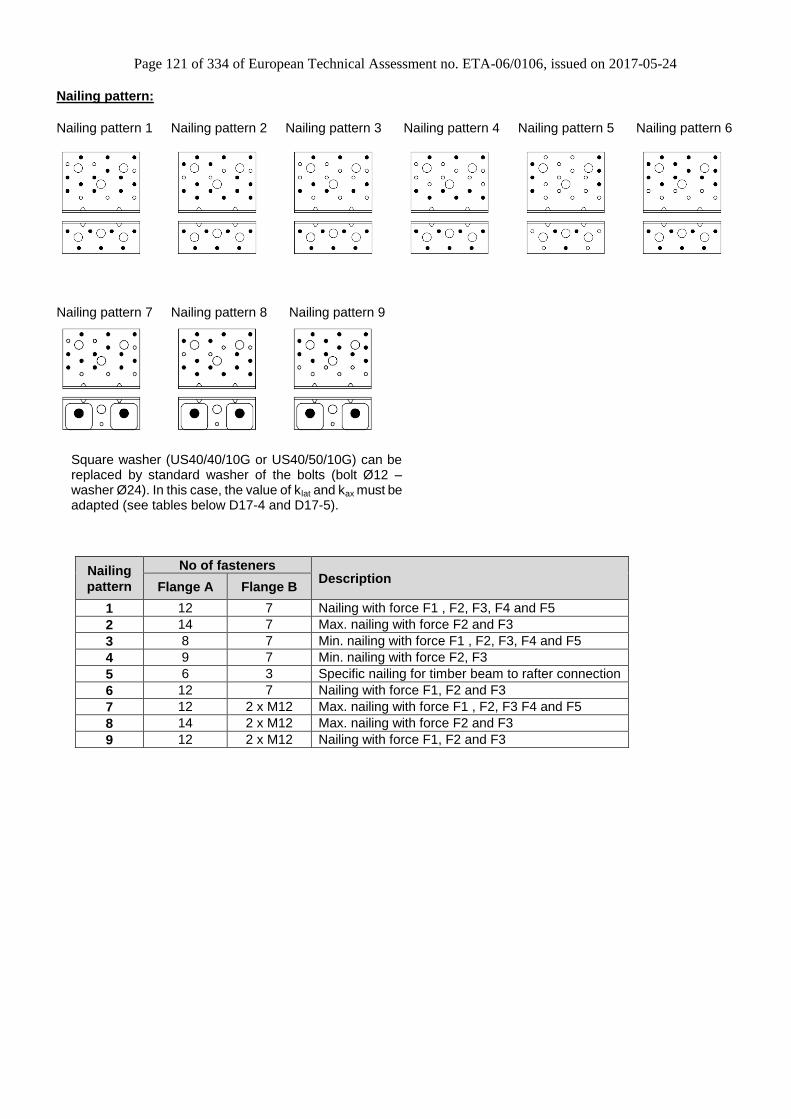
Page 121 of 334 of European Technical Assessment no. ETA-06/0106, issued on 2017-05-24
Nailing pattern: Nailing pattern 1 Nailing pattern 2 Nailing pattern 3 Nailing pattern 4 Nailing pattern 5 Nailing pattern 6
Nailing pattern 7 Nailing pattern 8 Nailing pattern 9
Nailing
pattern
No of fasteners Description
Flange A Flange B
1 12 7 Nailing with force F1 , F2, F3, F4 and F5
2 14 7 Max. nailing with force F2 and F3
3 8 7 Min. nailing with force F1 , F2, F3, F4 and F5
4 9 7 Min. nailing with force F2, F3
5 6 3 Specific nailing for timber beam to rafter connection
6 12 7 Nailing with force F1, F2 and F3
7 12 2 x M12 Max. nailing with force F1 , F2, F3 F4 and F5
8 14 2 x M12 Max. nailing with force F2 and F3
9 12 2 x M12 Nailing with force F1, F2 and F3
Square washer (US40/40/10G or US40/50/10G) can be replaced by standard washer of the bolts (bolt Ø12 – washer Ø24). In this case, the value of klat and kax must be adapted (see tables below D17-4 and D17-5).
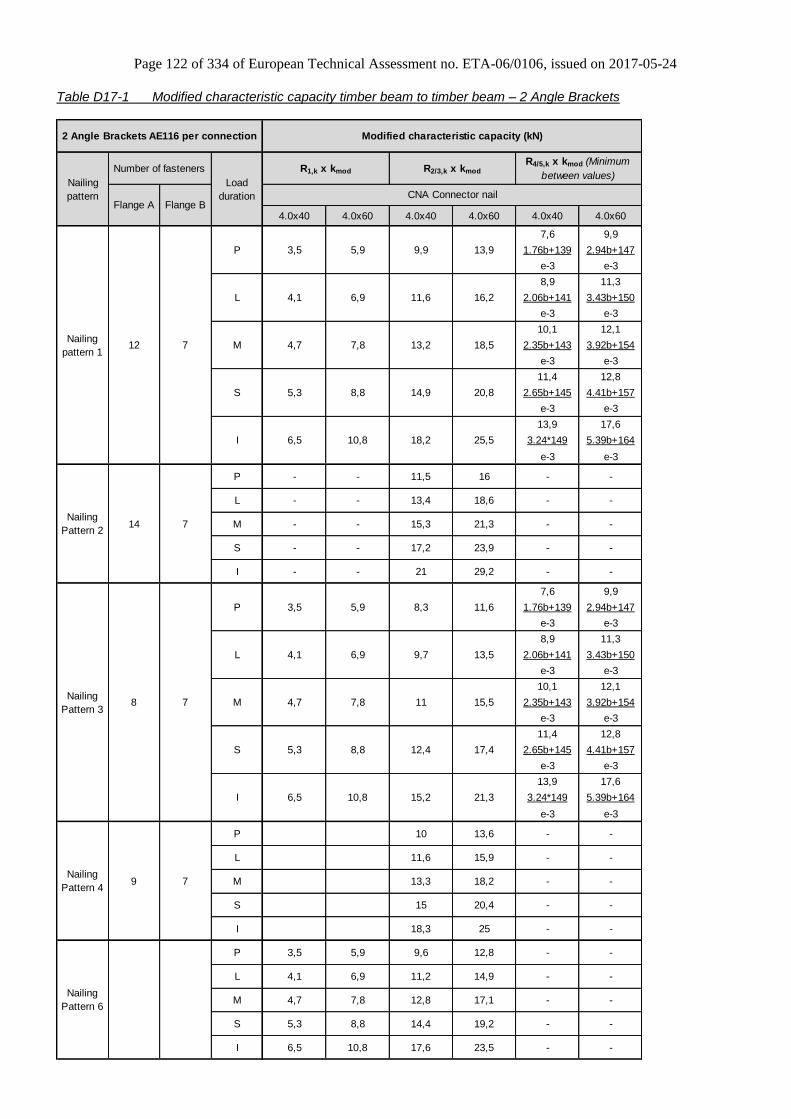
Page 122 of 334 of European Technical Assessment no. ETA-06/0106, issued on 2017-05-24
Table D17-1 Modified characteristic capacity timber beam to timber beam – 2 Angle Brackets
4.0x40 4.0x60 4.0x40 4.0x60 4.0x40 4.0x60
7,6 9,9
1.76b+139 2.94b+147
e-3 e-3
8,9 11,3
2.06b+141 3.43b+150
e-3 e-3
10,1 12,1
2.35b+143 3.92b+154
e-3 e-3
11,4 12,8
2.65b+145 4.41b+157
e-3 e-3
13,9 17,6
3.24*149 5.39b+164
e-3 e-3
7,6 9,9
1.76b+139 2.94b+147
e-3 e-3
8,9 11,3
2.06b+141 3.43b+150
e-3 e-3
10,1 12,1
2.35b+143 3.92b+154
e-3 e-3
11,4 12,8
2.65b+145 4.41b+157
e-3 e-3
13,9 17,6
3.24*149 5.39b+164
e-3 e-3
14,9
4,7 7,8 12,8 17,1
3,5
Number of fasteners
Flange A Flange B
12 7
14 7
8 7
9 7
- -
- -
- -
5,3 8,8 14,4 19,2
6,5 10,8 17,6 23,5
- -
- -
-
- -
- -
-
- -
- -
12,8
15 20,4
18,3 25
15,9
13,3 18,2
6,5 10,8 15,2 21,3
10 13,6
15,5
5,3 8,8 12,4 17,4
5,9 8,3 11,6
4,1 6,9 9,7 13,5
Nailing
Pattern 6
P
L
M
S
I
4,7 7,8 11
11,6
5,9 9,6
4,1 6,9 11,2
Nailing
Pattern 4
P
L
M
S
I
Modified characteristic capacity (kN)2 Angle Brackets AE116 per connection
Nailing
pattern
Nailing
Pattern 3
P
L
M
S
I
3,5
M
S
I
5,3
R4/5,k x kmod (Minimum
between values)R2/3,k x kmodR1,k x kmod
8,8
CNA Connector nailLoad
duration
3,5 5,9
4,1
4,7
P
L
20,8
9,9
14,9
6,5
6,9
7,8
18,2
11,5
10,8
13,2 18,5
--
25,5
23,9
- - 21 29,2
18,6
- - 15,3 21,3
- - 13,4
-
-
-
-
-
Nailing
pattern 1
Nailing
Pattern 2
-
-
-
-
-
P
L
M
S
I
- - 17,2
16
13,9
11,6 16,2
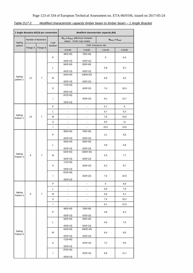
Page 123 of 334 of European Technical Assessment no. ETA-06/0106, issued on 2017-05-24
Table D17-2 Modified characteristic capacity timber beam to timber beam – 1 Angle Bracket
4.0x40 4.0x60 4.0x40 4.0x60
48/(f+40) 79/(f+40)
42/(f+13) 42/(f+13)
56/(f+40) 93/(f+40)
42/(f+13) 42/(f+13)
64/(f+40) 106/(f+40)
42/(f+13) 42/(f+13)
71/(f+40)
42/(f+13)
42/(f+13)
87/(f+40)
42/(f+13)
42/(f+13)
48/(f+40) 79/(f+40)
42/(f+13) 42/(f+13)
56/(f+40) 93/(f+40)
42/(f+13) 42/(f+13)
64/(f+40) 106/(f+40)
42/(f+13) 42/(f+13)
71/(f+40)
42/(f+13)
42/(f+13)
87/(f+40)
42/(f+13)
42/(f+13)
48/(f+40) 79/(f+40)
42/(f+13) 42/(f+13)
56/(f+40) 93/(f+40)
42/(f+13) 42/(f+13)
64/(f+40) 106/(f+40)
42/(f+13) 42/(f+13)
71/(f+40)
42/(f+13)
42/(f+13)
87/(f+40)
42/(f+13)
42/(f+13)
Flange A Flange B
12 7
14 7
8 7
9 7
Nailing
Pattern 6
P 4,8 6,4
M 6,4
I 8,8 11,7
8,5
S 7,2 9,6
L 5,6 7,5
M 5,5 7,7
- - 6,6 9,1
- 9,1 12,5
7,9
MNailing
Pattern 4
P - - 5 6,8
L - - 5,8
S - - 7,5 10,2
I -
Nailing
Pattern 3
P 4,1 5,8
L
I - - 10,5 14,6
Nailing
Pattern 2
P - - 5,7 8
S 6,2 8,7
I 7,6 10,6
4,8 6,8
10,6
S - - 8,6 12
L - - 6,7 9,3
M - - 7,6
Nailing
pattern 1
P 5 6,9
L 5,8
1 Angle Brackets AE116 per connection
Nailing
pattern
Load
duration
R1,k x kmod (Minimum between
values - Purlin may rotate)R2/3,k x kmod
S 7,4 10,4
I 9,1 12,7
8,1
M 6,6 9,3
Modified characteristic capacity (kN)
CNA Connector nail
Number of fasteners
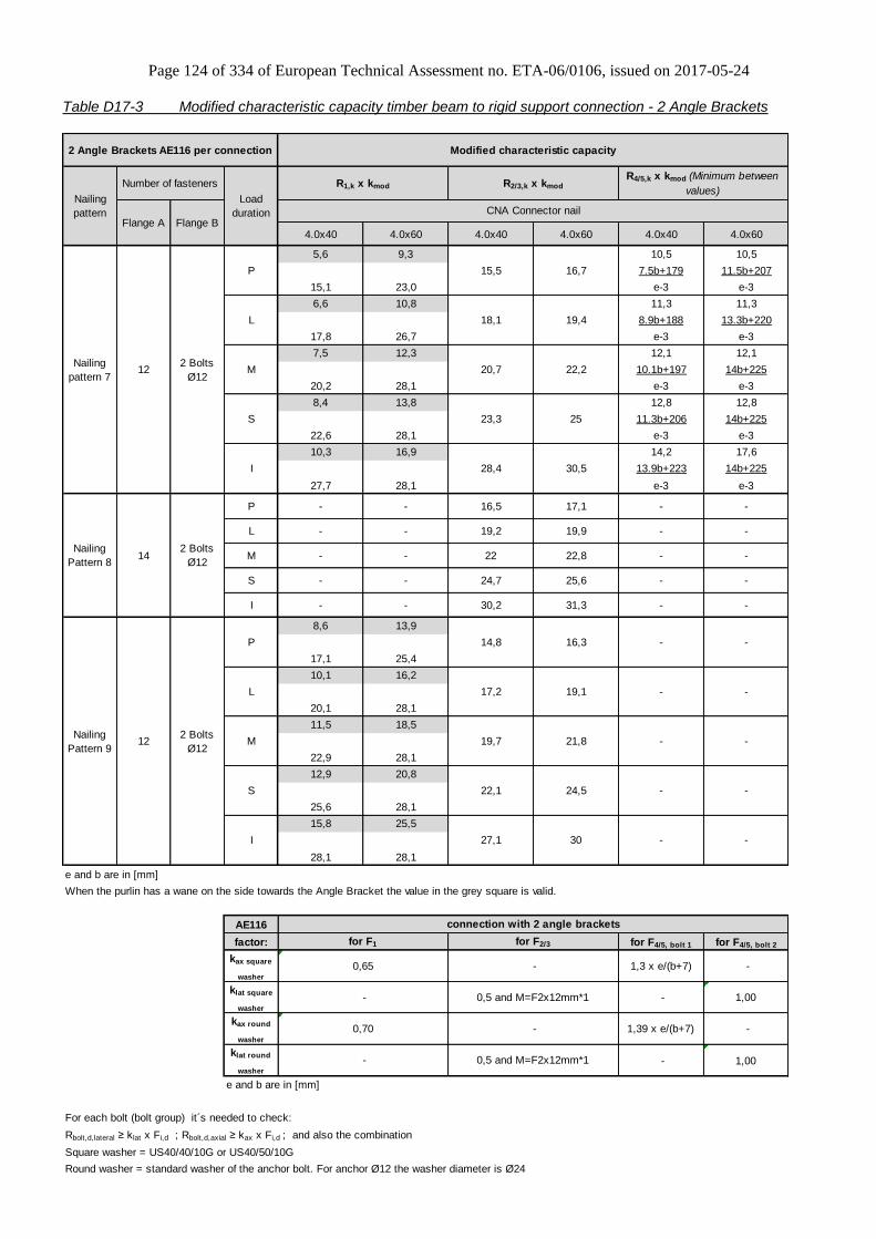
Page 124 of 334 of European Technical Assessment no. ETA-06/0106, issued on 2017-05-24
Table D17-3 Modified characteristic capacity timber beam to rigid support connection - 2 Angle Brackets
4.0x40 4.0x60 4.0x40 4.0x60 4.0x40 4.0x60
5,6 9,3 10,5 10,5
7.5b+179 11.5b+207
15,1 23,0 e-3 e-3
6,6 10,8 11,3 11,3
8.9b+188 13.3b+220
17,8 26,7 e-3 e-3
7,5 12,3 12,1 12,1
10.1b+197 14b+225
20,2 28,1 e-3 e-3
8,4 13,8 12,8 12,8
11.3b+206 14b+225
22,6 28,1 e-3 e-3
10,3 16,9 14,2 17,6
13.9b+223 14b+225
27,7 28,1 e-3 e-3
8,6 13,9
17,1 25,4
10,1 16,2
20,1 28,1
11,5 18,5
22,9 28,1
12,9 20,8
25,6 28,1
15,8 25,5
28,1 28,1
AE116
factor: for F4/5, bolt 1 for F4/5, bolt 2
kax square
washer
1,3 x e/(b+7) -
klat square
washer
- 1,00
kax round
washer
1,39 x e/(b+7) -
klat round
washer
- 1,00
e and b are in [mm]
For each bolt (bolt group) it´s needed to check:
Rbolt,d,lateral ≥ klat x Fi,d ; Rbolt,d,axial ≥ kax x Fi,d ; and also the combination
Square washer = US40/40/10G or US40/50/10G
Round washer = standard washer of the anchor bolt. For anchor Ø12 the washer diameter is Ø24
122 Bolts
Ø12
142 Bolts
Ø12
122 Bolts
Ø12
2 Angle Brackets AE116 per connection Modified characteristic capacity
Nailing
pattern
Load
duration
R1,k x kmod R2/3,k x kmod
R4/5,k x kmod (Minimum between
values)
CNA Connector nail
Number of fasteners
Flange A Flange B
19,4
M 20,7 22,2Nailing
pattern 7
P 15,5 16,7
L 18,1
S 23,3 25
I 28,4 30,5
- -
L - - 19,2 19,9 - -
P - - 16,5 17,1
22,8 - -
S - - 24,7 25,6 - -
M - - 22
-
Nailing
Pattern 9
P 14,8 16,3
L
I - - 30,2 31,3 -
Nailing
Pattern 8
17,2 19,1
M 19,7 21,8
- -S 22,1 24,5
- -
- -
- -
- -
for F1
0,65
-
When the purlin has a wane on the side towards the Angle Bracket the value in the grey square is valid.
I 27,1 30
0,70
-
e and b are in [mm]
connection with 2 angle brackets
for F2/3
-
0,5 and M=F2x12mm*1
-
0,5 and M=F2x12mm*1

Page 125 of 334 of European Technical Assessment no. ETA-06/0106, issued on 2017-05-24
Table D17-4 Modified characteristic capacity timber beam to rigid support – 1 Angle Bracket
4.0x40 4.0x60 4.0x40 4.0x60
f is in [mm]
AE116
factor:
kax square
washerklat square
washerkax round
washerklat round
washerf is in [mm]
For each bolt (bolt group) it´s needed to check:
Rbolt,d,lateral ≥ klat x Fi,d ; Rbolt,d,axial ≥ kax x Fi,d ; and also the combination
Square washer = US40/40/10G or US40/50/10G
Round washer = standard washer of the anchor bolt. For anchor Ø12 the washer diameter is Ø24
1 Angle Bracket AE116 per connection
Nailing
pattern
Load
duration
R1,k x kmod
(Purlin may rotate)R2/3,k x kmod
CNA Connector nail
Modified characteristic capacity
Number of fasteners
Flange A Flange B
8,3
L 42/(f+9) 42/(f+9) 9 9,7
Nailing
pattern 7
P 42/(f+9) 42/(f+9) 7,8
M 42/(f+9) 42/(f+9) 10,3122 Bolts
Ø1211,1
I 42/(f+9) 42/(f+9) 14,2 15,3
S 42/(f+9) 42/(f+9) 11,6 12,5
8,5
M - - 11
10
11,4Nailing
Pattern 8
P - - 8,2
L - - 9,6
S - - 12,4
142 Bolts
Ø12
12,8
8,2
L 42/(f+9) 42/(f+9)
I - - 15,1 15,7
9,5
Nailing
Pattern 9
P 42/(f+9) 42/(f+9) 7,4
8,6
M 42/(f+9) 42/(f+9) 9,8122 Bolts
Ø1210,9
connection with 1 angle brackets
S 42/(f+9) 42/(f+9) 11,1 12,3
I 42/(f+9) 42/(f+9) 13,5 15
for F1
(f+44)/23
-
(f+44)/23
-
for F2/3
0,18
1,00
0,18
1,00

Page 126 of 334 of European Technical Assessment no. ETA-06/0106, issued on 2017-05-24
Table D17-5 Modified characteristic capacity timber beam to rafter connection - 2 Angle Brackets
Nailing pattern 5)
2 Angle Brackets
per connection
Load duration: I
Symmetrical
R6,sy mmetrical on
each of two rafters
80 90 100 120 >80 80 90 100 120
R6,symmetrical [kN]
0 4,5 4,6 4,6 4,6 2,7 0 0 0 0
5 4,6 4,6 4,6 4,7 2,7 3 4 4 5
10 4,6 4,6 4,7 4,7 2,7 7 8 9 11
15 4,7 4,7 4,7 4,7 2,8 11 12 13 16
20 4,7 4,7 4,7 4,7 2,9 15 16 18 22
25 4,7 4,8 4,8 4,8 3,0 19 21 23 28
30 4,8 4,8 4,8 4,8 3,1 23 26 29 35
35 4,8 4,8 4,8 4,8 3,3 28 32 35 42
40 4,9 4,9 4,9 4,9 3,5 34 38 42 50
45 4,9 4,9 4,9 4,9 3,8 40 45 50 60
Same roof pitch at both side of the roof
Connector nail according to ETA-04/0013 4,0x40 in rafter and 4,0x60 in ridge beam
P L M S
0,55 0,64 0,73 0,82
The capacities in the table are for Instant load duration, the capacities for other load durations are found
by multiplication by the factor c
Factor c for other
load durations
Modified characteristic capacity per connection
Height hcontact of contact area
between rafter and ridge beam
Roof pitch
α [°]
R6,singlesided on one rafter
bridgebeam [mm]
R6,singlesided [kN] hcontact [mm]
Tension Compression
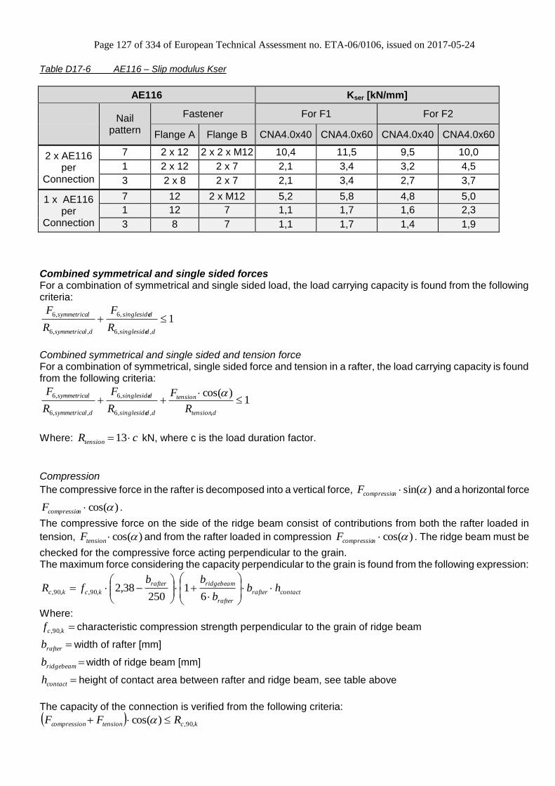
Page 127 of 334 of European Technical Assessment no. ETA-06/0106, issued on 2017-05-24
Table D17-6 AE116 – Slip modulus Kser
AE116 Kser [kN/mm]
Nail
pattern
Fastener For F1 For F2
Flange A Flange B CNA4.0x40 CNA4.0x60 CNA4.0x40 CNA4.0x60
2 x AE116 per
Connection
7 2 x 12 2 x 2 x M12 10,4 11,5 9,5 10,0
1 2 x 12 2 x 7 2,1 3,4 3,2 4,5
3 2 x 8 2 x 7 2,1 3,4 2,7 3,7
1 x AE116 per
Connection
7 12 2 x M12 5,2 5,8 4,8 5,0
1 12 7 1,1 1,7 1,6 2,3
3 8 7 1,1 1,7 1,4 1,9
Combined symmetrical and single sided forces For a combination of symmetrical and single sided load, the load carrying capacity is found from the following criteria:
1,,6
,6
,,6
,6
ddsingleside
dsingleside
dlsymmetrica
lsymmetrica
R
F
R
F
Combined symmetrical and single sided and tension force For a combination of symmetrical, single sided force and tension in a rafter, the load carrying capacity is found from the following criteria:
1)cos(
,,,6
,6
,,6
,6
dtension
tension
ddsingleside
dsingleside
dlsymmetrica
lsymmetrica
R
F
R
F
R
F
Where: cRtension 13 kN, where c is the load duration factor.
Compression
The compressive force in the rafter is decomposed into a vertical force, )sin(ncompressioF and a horizontal force
)cos(ncompressioF .
The compressive force on the side of the ridge beam consist of contributions from both the rafter loaded in
tension, )cos(tensionF and from the rafter loaded in compression )cos(ncompressioF . The ridge beam must be
checked for the compressive force acting perpendicular to the grain. The maximum force considering the capacity perpendicular to the grain is found from the following expression:
contactrafter
rafter
ridgebeamrafter
kckc hbb
bbfR
61
25038,2,90,,90,
Where:
kcf ,90, characteristic compression strength perpendicular to the grain of ridge beam
rafterb width of rafter [mm]
ridgebeamb width of ridge beam [mm]
contacth height of contact area between rafter and ridge beam, see table above
The capacity of the connection is verified from the following criteria:
kctensionompressionc RFF ,90,)cos(
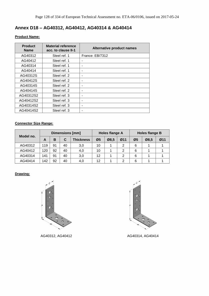
Page 128 of 334 of European Technical Assessment no. ETA-06/0106, issued on 2017-05-24
Annex D18 – AG40312, AG40412, AG40314 & AG40414
Product Name:
Product
Name
Material reference
acc. to clause II-1 Alternative product names
AG40312 Steel ref. 1 France: EB/7312
AG40412 Steel ref. 1 -
AG40314 Steel ref. 1 -
AG40414 Steel ref. 1 -
AG40312S Steel ref. 2 -
AG40412S Steel ref. 2 -
AG40314S Steel ref. 2 -
AG40414S Steel ref. 2 -
AG40312S2 Steel ref. 3 -
AG40412S2 Steel ref. 3 -
AG40314S2 Steel ref. 3 -
AG40414S2 Steel ref. 3 -
Connector Size Range:
Model no. Dimensions [mm] Holes flange A Holes flange B
A B C Thickness Ø5 Ø8,5 Ø11 Ø5 Ø8,5 Ø11
AG40312 119 91 40 3,0 10 1 2 6 1 1
AG40412 120 92 40 4,0 10 1 2 6 1 1
AG40314 141 91 40 3,0 12 1 2 6 1 1
AG40414 142 92 40 4,0 12 1 2 6 1 1
Drawing:
AG40312, AG40412
AG40314, AG40414

Page 129 of 334 of European Technical Assessment no. ETA-06/0106, issued on 2017-05-24
Nailing pattern:
Nailing pattern 1 Nailing pattern 2 Nailing pattern 3 Nailing pattern 4
Flange A:
Flange B:
Beam to beam,
(AG40312, AG40412)
Beam (A) to column (B), (AG40312, AG40412)
Beam to beam, (AG40314, AG40414)
Beam (A) to column (B), (AG40314, AG40414)
Nailing pattern 5 Nailing pattern 6 Nailing pattern 7 Nailing pattern 8
Flange A:
Flange B:
Beam (A) to rigid support (B), (AG40312, AG40412)
Column (A) to rigid support (B), (AG40312, AG40412)
Beam (A) to rigid support (B), (AG40314, AG40414)
Column (A) to rigid support (B), (AG40314, AG40414)

Page 130 of 334 of European Technical Assessment no. ETA-06/0106, issued on 2017-05-24
Table D18-1 Modified characteristic capacity timber beam to timber beam or timber beam to timber column – 2
Angle Brackets
4,0x40 4,0x60 4,0x40 4,0x60 4,0x40 4,0x60
e≤0,29b+15 e≤0,43b+18
4,6 4,6
e>0,29b+15 e>0,43b+18
1,32b+56 1,96b+70
e-3,0 e-3,0
e≤0,27b+15 e≤0,42b+18
4,3 4,3
e>0,27b+15 e>0,42b+18
1,18b+52 1,80b+66
e-3,0 e-3,0
b and e are in mm
4,0x40 4,0x60 4,0x40 4,0x60 4,0x40 4,0x60
1,19 1,16 1,22 1,22 1,11 1,11
0,88 0,91 0,88 0,88 0,88 0,92
0,75 0,81 0,75 0,75 0,78 0,83
4,0
2,7 3,9 4,5
2,4 3,6
R1,k R2/3,k
S 3,0
M 2,6
Nailing
patterns
1, 2, 3, 4
CNA Connector nail
2 Angle Brackets
AG40312 or AG40314
per connection
Modified characteristic capacity per connection (kN)
R1,k x kmod R2/3,k x kmod R4/5,k x kmod
Load
duration CNA Connector nail
R4/5,k
I multiply S by
L multiply M by
P multiply M by
Number of fasteners
Flange A Flange B
4 4
Factors for other
load durations
Nailing
pattern

Page 131 of 334 of European Technical Assessment no. ETA-06/0106, issued on 2017-05-24
Table D18-2 Modified characteristic capacity timber beam to timber beam or timber beam to timber column – 1
Angle Bracket
4,0x40 4,0x60 4,0x40 4,0x60
min:
55
f + 81 20
20 f + 19
f + 19
20 20
f + 19 f + 19
20 20
f + 19 f + 19
20 20
f + 19 f + 19
20 20
f + 19 f + 19
f is in mm
1,5
P 1,0 1,4
S
Number of fasteners
Flange A Flange B
4 4
Modified characteristic capacity per connection (kN)
R1,k x kmod
Purlin may rotate
R2/3,k x kmod
M
1,2
1,3
L
Load
duration
1,8
1,7
1,9
2,1
2,6
1 Angle Bracket
AG40312 or AG40314
per connection
Nailing
pattern CNA Connector nail
Nailing
patterns
1, 2, 3, 4
I

Page 132 of 334 of European Technical Assessment no. ETA-06/0106, issued on 2017-05-24
Table D18-3 Modified characteristic capacity timber beam to timber beam or timber beam to timber column – 2
Angle Brackets
4,0x40 4,0x60 4,0x40 4,0x60 4,0x40 4,0x60
e≤ 0,22b+16 e≤ 0,36b+19
6,1 6,1
e> 0,22b+16 e> 0,36b+19
1,32b+76 2,21b+96
e-4,0 e-4,0
e≤ 0,20b+16 e≤ 0,34b+19
5,75 5,75
e> 0,20b+16 e> 0,34b+19
1,18b+73 1,96b+90
e-4,0 e-4,0
f are in mm
4,0x40 4,0x60 4,0x40 4,0x60 4,0x40 4,0x60
1,22 1,22 1,22 1,22 1,10 1,10
0,88 0,88 0,88 0,88 0,85 0,89
0,75 0,75 0,75 0,75 0,65 0,78
CNA Connector nail
S
R2/3,k R4/5,kR1,k
M 2,6
Load
duration
Modified characteristic capacity per connection (kN)
R1,k x kmod R2/3,k x kmod R4/5,k x kmod
2 Angle Brackets
AG40412 or AG40414
per connection
Nailing
pattern CNA Connector nail
Number of fasteners
Flange A
3,52,4 3,9
2,7 4,4 2,9 4,0
P multiply M by
Flange B
4 4
I multiply S by
Factors for other
load durations
L multiply M by
Nailing
patterns
1, 2, 3, 4

Page 133 of 334 of European Technical Assessment no. ETA-06/0106, issued on 2017-05-24
Table D18-4 Modified characteristic capacity timber beam to timber beam or timber beam to timber column – 1
Angle Bracket
4,0x40 4,0x60 4,0x40 4,0x60
min: min:
55 91
f + 82 f + 82
35 35,0
f + 20 f + 20
min: min:
64 106
f + 82 f + 82
35 35,0
f + 20 f + 20
min: min:
73 122
f + 82 f + 82
35 35
f + 20 f + 20
min:
82
f + 82 35
35 f + 20
f + 20
min:
100,0
f + 82 35
35,0 f + 20
f + 20
f is in mm.
Number of fasteners
Flange A Flange B
4 4
S 1,5 2,0
I 1,8 2,4
R2/3,k x kmod
M 1,3 1,8
L
Load
duration
P
1 Angle Bracket
AG40412 or AG40414
per connection
Nailing
pattern CNA Connector nail
1,0 1,3
1,1 1,6
Nailing
patterns
1, 2, 3, 4
Modified characteristic capacity per connection (kN)
R1,k x kmod
Purlin may rotate
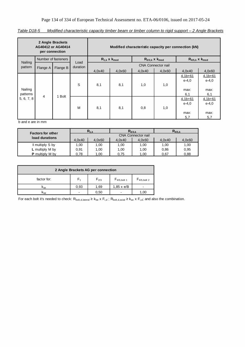
Page 134 of 334 of European Technical Assessment no. ETA-06/0106, issued on 2017-05-24
Table D18-5 Modified characteristic capacity timber beam or timber column to rigid support – 2 Angle Brackets
4,0x40 4,0x60 4,0x40 4,0x60 4,0x40 4,0x60
4,1b+61 4,1b+61
e-4,0 e-4,0
max: max:
6,1 6,1
4,1b+61 4,1b+61
e-4,0 e-4,0
max: max:
5,7 5,7
b and e are in mm
4,0x40 4,0x60 4,0x40 4,0x60 4,0x40 4,0x60
1,00 1,00 1,00 1,00 1,00 1,00
0,91 1,00 1,00 1,00 0,86 0,95
0,78 1,00 0,75 1,00 0,67 0,88
F1 F2/3 F4/5,bolt 1 F4/5,bolt 2
0,93 1,69 1,85 x e/B -
- 0,50 - 1,00
For each bolt it's needed to check: Rbolt,d,lateral ≥ klat x Fi,d ; Rbolt,d,axial ≥ kax x Fi,d; and also the combination.
1,08,1 8,1
8,1
R4/5,k
1,0
R1,k R2/3,k
S
CNA Connector nail
M 0,8 1,08,1
Modified characteristic capacity per connection (kN)
R1,k x kmod R2/3,k x kmod R4/5,k x kmod
2 Angle Brackets
AG40412 or AG40414
per connection
Nailing
pattern CNA Connector nailLoad
duration
Nailing
patterns
5, 6, 7, 8
Number of fasteners
Flange A Flange B
4 1 Bolt
Factors for other
load durations
I multiply S by
L multiply M by
P multiply M by
factor for:
kax
klat
2 Angle Brackets AG per connection

Page 135 of 334 of European Technical Assessment no. ETA-06/0106, issued on 2017-05-24
Table D18-6 Modified characteristic capacity timber beam or timber column to rigid support – 1 Angle Bracket
4,0x40 4,0x60 4,0x40 4,0x60
min: min:
47 47
f+7 f+7
148 148
f+67 f+67
min: min:
47 47
f+7 f+7
148 148
f+67 f+67
f is in mm
4,0x40 4,0x60 4,0x40 4,0x60
1,00 1,00 1,00 1,00
1,00 1,00 1,00 1,00
1,00 1,00 0,75 1,00
F1 F2/3 F4 F5
1,85 3,38 - -
- 1,00 - -
For each bolt it's needed to check: Rbolt,d,lateral ≥ klat x Fi,d ; Rbolt,d,axial ≥ kax x Fi,d; and also the combination.
S
1 Angle Bracket AG per connection
0,5
Modified characteristic capacity per connection (kN)
R1,k x kmod
Purlin may rotate
R2/3,k x kmod
Load
duration
R2/3,k
1 Angle Brackets
AG40412 or AG40414
per connection
Nailing
pattern CNA Connector nail
CNA Connector nail
M
0,5 0,5
0,4
R1,k
Purlin may rotate
Number of fasteners
Flange A Flange B
4 1 Bolt
Factors for other
load durations
Nailing
patterns
5, 6, 7, 8
I multiply S by
L multiply M by
P multiply M by
factor for:
kax
klat
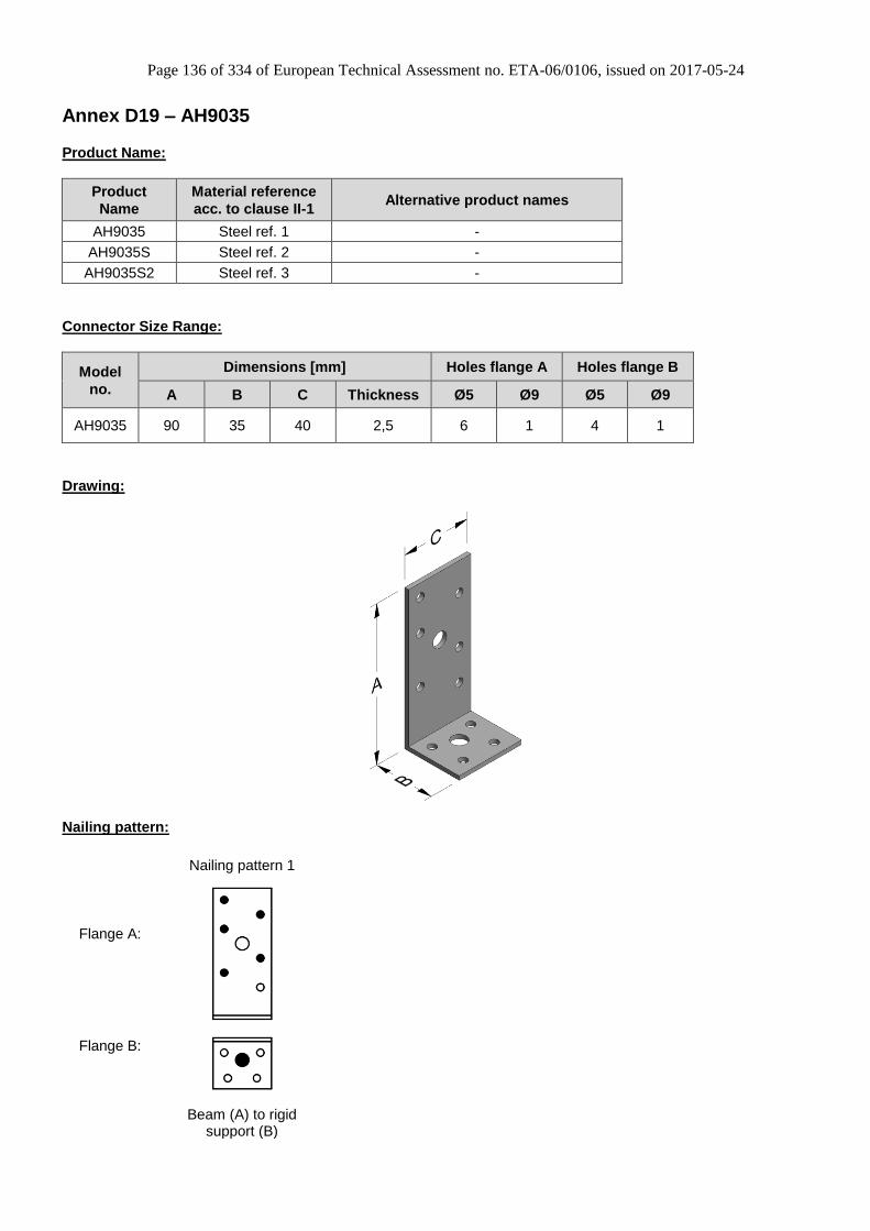
Page 136 of 334 of European Technical Assessment no. ETA-06/0106, issued on 2017-05-24
Annex D19 – AH9035
Product Name:
Product
Name
Material reference
acc. to clause II-1 Alternative product names
AH9035 Steel ref. 1 -
AH9035S Steel ref. 2 -
AH9035S2 Steel ref. 3 -
Connector Size Range:
Model
no.
Dimensions [mm] Holes flange A Holes flange B
A B C Thickness Ø5 Ø9 Ø5 Ø9
AH9035 90 35 40 2,5 6 1 4 1
Drawing:
Nailing pattern:
Nailing pattern 1
Flange A:
Flange B:
Beam (A) to rigid
support (B)
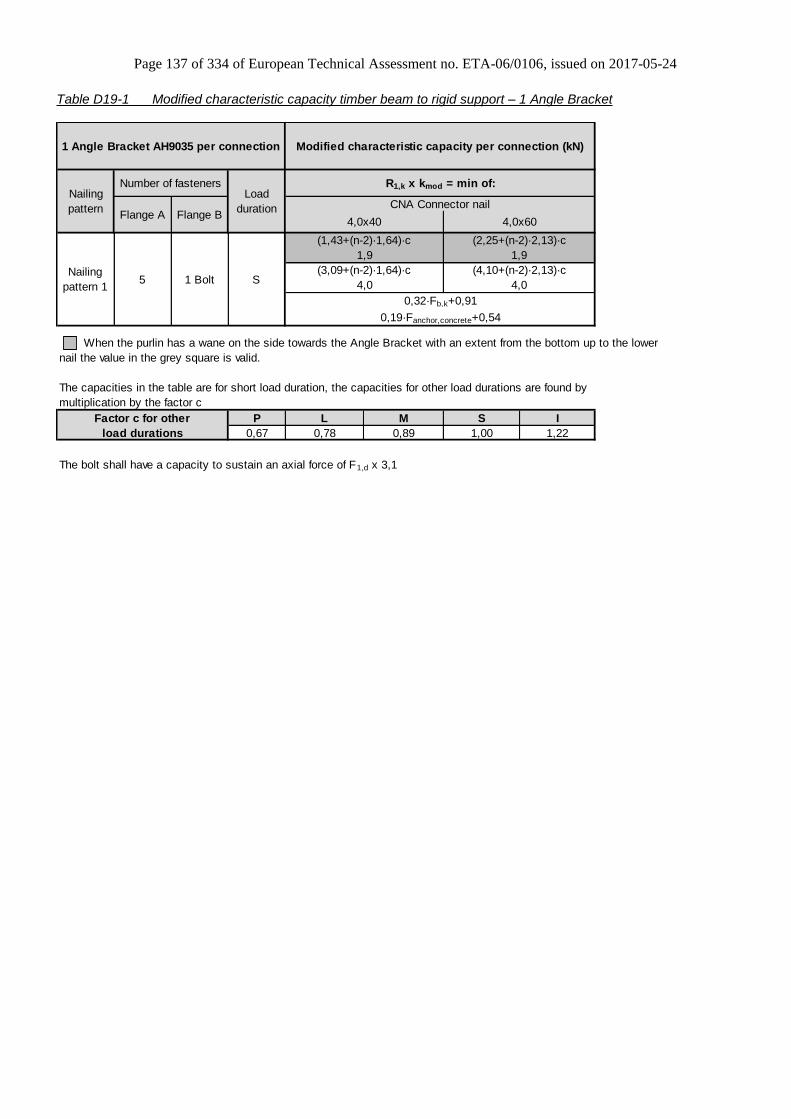
Page 137 of 334 of European Technical Assessment no. ETA-06/0106, issued on 2017-05-24
Table D19-1 Modified characteristic capacity timber beam to rigid support – 1 Angle Bracket
P L M S I
0,67 0,78 0,89 1,00 1,22
The bolt shall have a capacity to sustain an axial force of F1,d x 3,1
1 Angle Bracket AH9035 per connection
5 1 BoltNailing
pattern 1S
Factor c for other
load durations
The capacities in the table are for short load duration, the capacities for other load durations are found by
multiplication by the factor c
0,32·Fb,k+0,91
0,19·Fanchor,concrete+0,54
(3,09+(n-2)·1,64)·c
Modified characteristic capacity per connection (kN)
R1,k x kmod = min of:
4,0x40 4,0x60
(1,43+(n-2)·1,64)·c (2,25+(n-2)·2,13)·c
Nailing
pattern
Number of fastenersLoad
duration
When the purlin has a wane on the side towards the Angle Bracket with an extent from the bottom up to the lower
nail the value in the grey square is valid.
CNA Connector nail
(4,10+(n-2)·2,13)·c
4,0 4,0
1,9 1,9
Flange A Flange B

Page 138 of 334 of European Technical Assessment no. ETA-06/0106, issued on 2017-05-24
Annex D20 – AJ60416
Product Name:
Product
Name
Material reference
acc. to clause II-1 Alternative product names
AJ60416 Steel ref. 1 -
AJ60416S Steel ref. 2 -
AJ60416S2 Steel ref. 3 -
Connector Size Range:
Model
no.
Dimensions [mm] Holes flange A Holes flange B
A B C Thickness Ø5 Ø5
AJ60416 164 84 60 4,0 8 7
Drawing:
Nailing pattern:
Nailing pattern 1
Flange A:
Flange B:
Beam to Beam
Full nailing
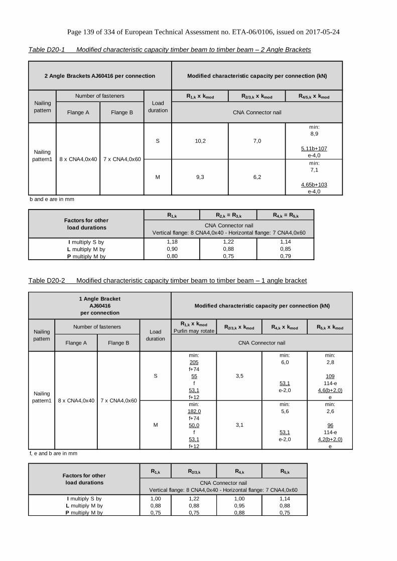
Page 139 of 334 of European Technical Assessment no. ETA-06/0106, issued on 2017-05-24
Table D20-1 Modified characteristic capacity timber beam to timber beam – 2 Angle Brackets
b and e are in mm
I multiply S by
L multiply M by
P multiply M by
Number of fasteners
Flange A Flange B
8 x CNA4,0x40 7 x CNA4,0x60
Factors for other
load durations
Nailing
pattern
Nailing
pattern1
2 Angle Brackets AJ60416 per connection
Load
duration
R4,k = R5,kR1,k R2,k = R3,k
S
M
10,2 7,0
min:
8,9
5,11b+107
e-4,0
4,65b+103
e-4,0
Modified characteristic capacity per connection (kN)
R1,k x kmod R2/3,k x kmod R4/5,k x kmod
9,3
1,22
6,2
7,1
min:
CNA Connector nail
CNA Connector nail
Vertical flange: 8 CNA4,0x40 - Horizontal flange: 7 CNA4,0x60
0,85
0,79
0,90
0,80
0,88
0,75
1,18 1,14
Table D20-2 Modified characteristic capacity timber beam to timber beam – 1 angle bracket
R1,k x kmod
Purlin may rotateR2/3,k x kmod R4,k x kmod R5,k x kmod
min: min: min:
205 6,0 2,8
f+74
55 109
f 53,1 114-e
53,1 e-2,0 4,6(b+2,0)
f+12 e
min: min: min:
182,0 5,6 2,6
f+74
50,0 96
f 53,1 114-e
53,1 e-2,0 4,2(b+2,0)
f+12 e
f, e and b are in mm
R1,k R2/3,k R4,k R5,k
1,00 1,22 1,00 1,14
0,88 0,88 0,95 0,88
0,75 0,75 0,88 0,75
Factors for other
load durations
I multiply S by
L multiply M by
P multiply M by
S
Nailing
pattern
1 Angle Bracket
AJ60416
per connection
Nailing
pattern1
Number of fasteners
Flange A Flange B
8 x CNA4,0x40 7 x CNA4,0x60
CNA Connector nail
CNA Connector nail
Vertical flange: 8 CNA4,0x40 - Horizontal flange: 7 CNA4,0x60
Modified characteristic capacity per connection (kN)
Load
duration
3,5
3,1M

Page 140 of 334 of European Technical Assessment no. ETA-06/0106, issued on 2017-05-24
Annex D21 – AJ80416
Product Name:
Product
Name
Material reference
acc. to clause II-1 Alternative product names
AJ80416 Steel ref. 1 -
AJ80416S Steel ref. 2 -
AJ80416S2 Steel ref. 3 -
Connector Size Range:
Model
no.
Dimensions [mm] Holes flange A Holes flange B
A B C Thickness Ø5 Ø5
AJ60416 164 84 80 4,0 8 7
Drawing:
Nailing pattern:
Nailing pattern 1
Flange A:
Flange B:
Beam to Beam
Full nailing

Page 141 of 334 of European Technical Assessment no. ETA-06/0106, issued on 2017-05-24
Table D21-1 Modified characteristic capacity timber beam to timber beam – 2 Angle Brackets
Flange A Flange B
b and e are in mm
P multiply M by
Number of fasteners
11 x CNA4,0x40 9 x CNA4,0x60
Factors for other
load durations
I multiply S by
L multiply M by
R1,k R2/3,k
S
M
14,0 9,0
1,18
Modified characteristic capacity per connection (kN)
R1,k x kmod R2/3,k x kmod R4/5,k x kmod
min:
12,4
Load
duration
R4/5,k
1,22
8,0
11,7
min:
6,39b+139
1,11
0,86
0,65
0,90
0,80
0,88
0,75
2 Angle Brackets AJ80416 per connection
Nailing
pattern
Nailing
pattern1
e-4,0
CNA Connector nail
CNA Connector nail
7,02b+144
e-4,0
12,8
Table D21-2 Modified characteristic capacity timber beam to timber beam – 1 Angle Bracket
R1,k x kmod R2/3,k x kmod R4,k x kmod R5,k x kmod
Flange A Flange B
min: min: min:
274 8,0 3,7
f+74
83 163
f 70,8 121-e
70,8 e-2,0 6,3(b+2,0)
f+12 e
min: min: min:
243 7,5 3,5
f+74
74 145
f 70,8 121-e
70,8 e-2,0 5,7(b+2,0)
f+12 e
f, e and b are in mm
R1,k R2/3,k R4,k R5,k
1,00 1,22 1,00 1,14
0,88 0,88 0,93 0,88
0,75 0,75 0,87 0,75
I multiply S by
L multiply M by
P multiply M by
CNA Connector nail
4,5
4,0M
S
11 x
CNA4,0x40
9 x
CNA4,0x60
Factors for other
load durations
1 Angle Bracket AJ80416 per connection
Nailing
pattern
Nailing
pattern1
Modified characteristic capacity per connection (kN)
CNA Connector nail
Load
duration
Number of fasteners
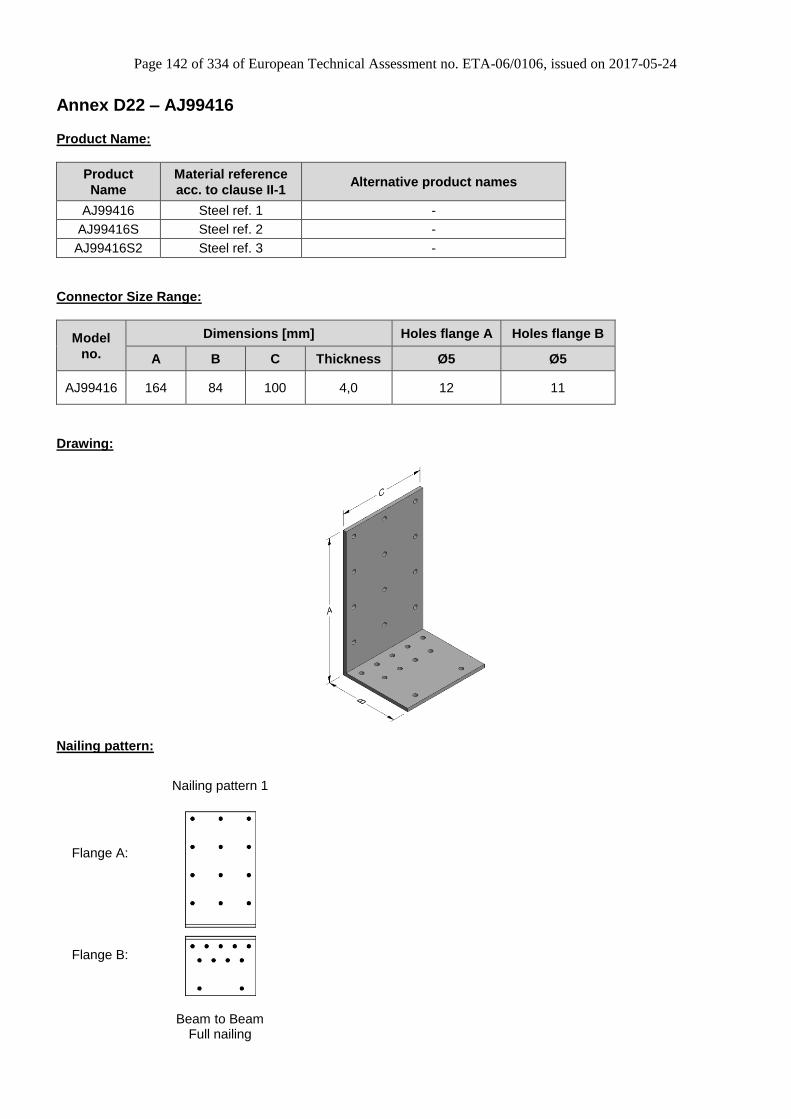
Page 142 of 334 of European Technical Assessment no. ETA-06/0106, issued on 2017-05-24
Annex D22 – AJ99416
Product Name:
Product
Name
Material reference
acc. to clause II-1 Alternative product names
AJ99416 Steel ref. 1 -
AJ99416S Steel ref. 2 -
AJ99416S2 Steel ref. 3 -
Connector Size Range:
Model
no.
Dimensions [mm] Holes flange A Holes flange B
A B C Thickness Ø5 Ø5
AJ99416 164 84 100 4,0 12 11
Drawing:
Nailing pattern:
Nailing pattern 1
Flange A:
Flange B:
Beam to Beam
Full nailing
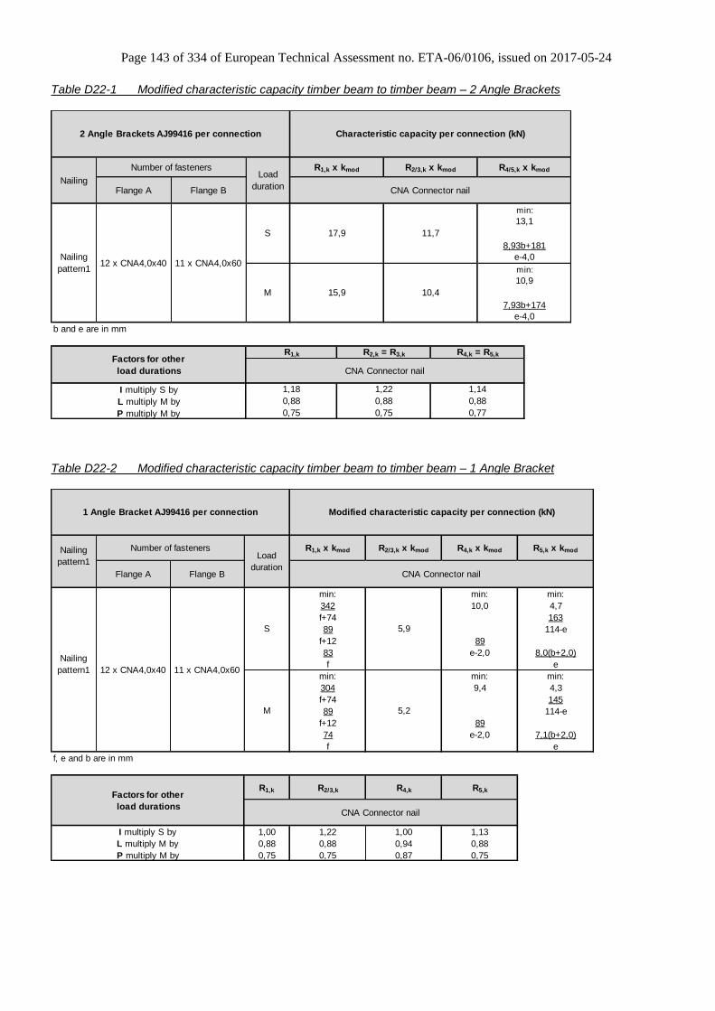
Page 143 of 334 of European Technical Assessment no. ETA-06/0106, issued on 2017-05-24
Table D22-1 Modified characteristic capacity timber beam to timber beam – 2 Angle Brackets
Flange A Flange B
b and e are in mm
P multiply M by
Number of fasteners
12 x CNA4,0x40 11 x CNA4,0x60
Factors for other
load durations
I multiply S by
L multiply M by
Load
duration
R4,k = R5,kR1,k R2,k = R3,k
S
M
17,9 11,7
Characteristic capacity per connection (kN)
R1,k x kmod R2/3,k x kmod R4/5,k x kmod
min:
13,1
15,9
1,22
10,4
10,9
min:
7,93b+174
0,88
0,77
0,88
0,75
0,88
0,75
1,14
2 Angle Brackets AJ99416 per connection
Nailing
Nailing
pattern1
e-4,0
CNA Connector nail
CNA Connector nail
1,18
8,93b+181
e-4,0
Table D22-2 Modified characteristic capacity timber beam to timber beam – 1 Angle Bracket
R1,k x kmod R2/3,k x kmod R4,k x kmod R5,k x kmod
Flange A Flange B
min: min: min:
342 10,0 4,7
f+74 163
89 114-e
f+12 89
83 e-2,0 8,0(b+2,0)
f e
min: min: min:
304 9,4 4,3
f+74 145
89 114-e
f+12 89
74 e-2,0 7,1(b+2,0)
f e
f, e and b are in mm
R1,k R2/3,k R4,k R5,k
1,00 1,22 1,00 1,13
0,88 0,88 0,94 0,88
0,75 0,75 0,87 0,75
Factors for other
load durations
I multiply S by
L multiply M by
P multiply M by
Load
duration
5,9
5,2
Number of fasteners
12 x CNA4,0x40 11 x CNA4,0x60
M
CNA Connector nail
1 Angle Bracket AJ99416 per connection
Nailing
pattern1
Nailing
pattern1
S
Modified characteristic capacity per connection (kN)
CNA Connector nail

Page 144 of 334 of European Technical Assessment no. ETA-06/0106, issued on 2017-05-24
Annex D23 – KNAG90, 130, 170 & 210
Product Name:
Product
Name
Material reference
acc. to clause II-1 Alternative product names
KNAG90 Steel ref. 1 France: ECH90/19090
KNAG130 Steel ref. 1 France: ECH125/19130
KNAG170 Steel ref. 1 France: ECH160/19170
KNAG210 Steel ref. 1 France: ECH200/19210
KNAG90S Steel ref. 2 -
KNAG130S Steel ref. 2 -
KNAG170S Steel ref. 2 -
KNAG210S Steel ref. 2 -
KNAG90S2 Steel ref. 3 -
KNAG130S2 Steel ref. 3 -
KNAG170S2 Steel ref. 3 -
KNAG210S2 Steel ref. 3 -
Connector Size Range:
Model no.
Dimensions [mm] Holes flange A Holes flange B
A B C
(A/B) Thickness Ø5 Ø5
KNAG90 90 90 55/65 2,0 6 8
KNAG130 125 125 64/80 2,0 9 10
KNAG170 160 160 80/95 2,0 11 12
KNAG210 200 200 84/100 2,0 14 14
Drawing:
KNAG90 KNAG130
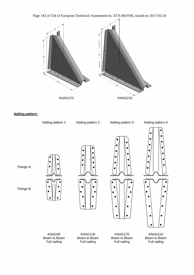
Page 145 of 334 of European Technical Assessment no. ETA-06/0106, issued on 2017-05-24
KNAG170 KNAG210
Nailing pattern:
Nailing pattern 1 Nailing pattern 2 Nailing pattern 3 Nailing pattern 4
Flange A:
Flange B:
KNAG90
Beam to Beam Full nailing
KNAG130 Beam to Beam
Full nailing
KNAG170 Beam to Beam
Full nailing
KNAG210 Beam to Beam
Full nailing
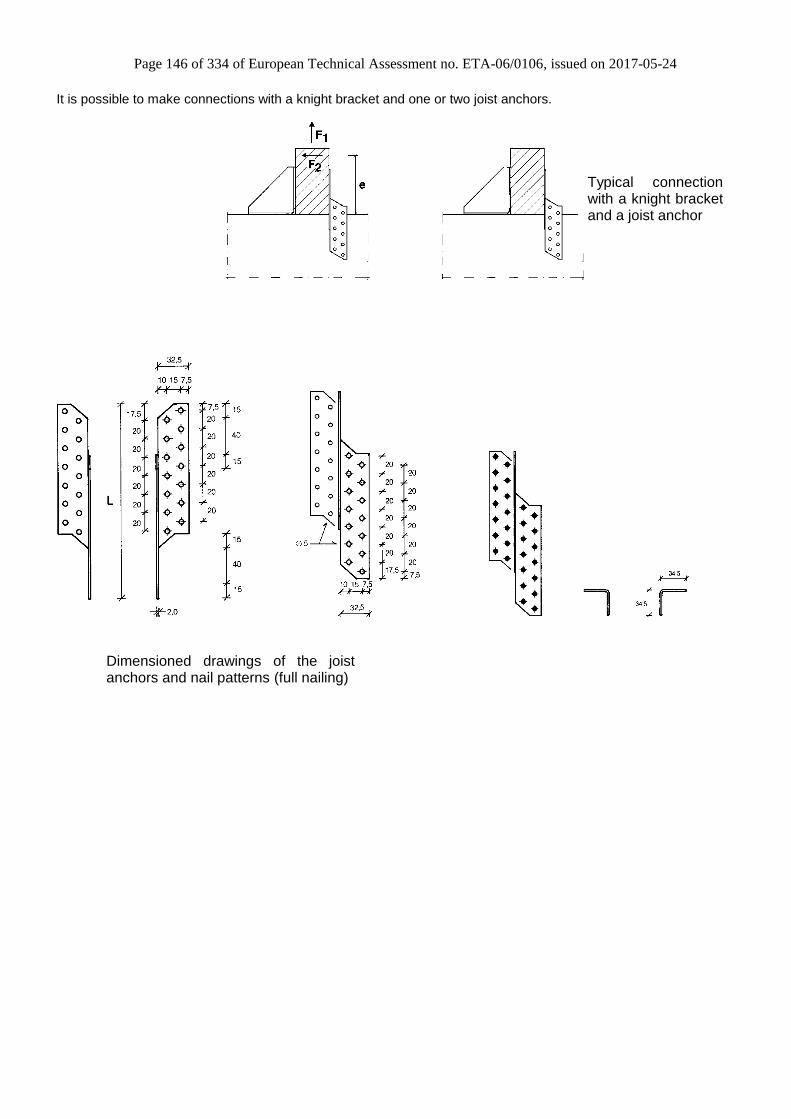
Page 146 of 334 of European Technical Assessment no. ETA-06/0106, issued on 2017-05-24
It is possible to make connections with a knight bracket and one or two joist anchors.
Typical connection with a knight bracket and a joist anchor
Dimensioned drawings of the joist anchors and nail patterns (full nailing)

Page 147 of 334 of European Technical Assessment no. ETA-06/0106, issued on 2017-05-24
One knight bracket per connection Acting forces
F1 Lifting force acting in the central axis of the angle bracket but in a distance f from the vertical flange of
the knight bracket
F2 Lateral force acting in the beam direction perpendicular to the vertical flange elevated e above the
beam directed towards the knight brackets vertical flange
One knight bracket and one or two joist anchors per connection Acting forces
F1 Lifting force acting in the central axis of the knight bracket
F2 Lateral force acting in the beam direction perpendicular to the vertical flange elevated e above the
beam directed towards the knight brackets vertical flange
Wane Wane is not allowed under the knight bracket.
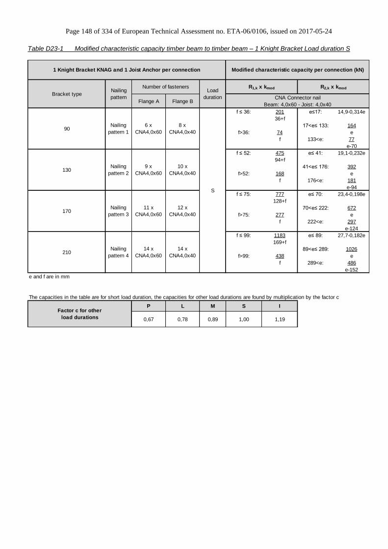
Page 148 of 334 of European Technical Assessment no. ETA-06/0106, issued on 2017-05-24
Table D23-1 Modified characteristic capacity timber beam to timber beam – 1 Knight Bracket Load duration S
Flange A Flange B
f ≤ 36: 201 e≤17: 14,9-0,314e
36+f
17<e≤ 133: 164
f>36: 74 e
f 133<e: 77
e-70
f ≤ 52: 475 e≤ 41: 19,1-0,232e
94+f
41<e≤ 176: 392
f>52: 168 e
f 176<e: 181
e-94
f ≤ 75: 777 e≤ 70: 23,4-0,198e
128+f
70<e≤ 222: 672
f>75: 277 e
f 222<e: 297
e-124
f ≤ 99: 1183 e≤ 89: 27,7-0,182e
169+f
89<e≤ 289: 1026
f>99: 438 e
f 289<e: 486
e-152
e and f are in mm
P L M S I
0,67 0,78 0,89 1,00 1,19
11 x
CNA4,0x60
14 x
CNA4,0x60
Factor c for other
load durations
R1,k x kmod R2,k x kmod
Modified characteristic capacity per connection (kN)
170
Nailing
pattern
Number of fasteners
Nailing
pattern 1
Nailing
pattern 2
Nailing
pattern 3
6 x
CNA4,0x60
CNA Connector nail
Beam: 4,0x60 - Joist: 4,0x40
210
The capacities in the table are for short load duration, the capacities for other load durations are found by multiplication by the factor c
90
130
Nailing
pattern 4
1 Knight Bracket KNAG and 1 Joist Anchor per connection
Load
durationBracket type
8 x
CNA4,0x40
S
10 x
CNA4,0x40
12 x
CNA4,0x40
14 x
CNA4,0x40
9 x
CNA4,0x60
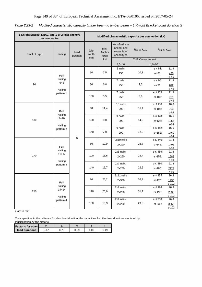
Page 149 of 334 of European Technical Assessment no. ETA-06/0106, issued on 2017-05-24
Table D23-2 Modified characteristic capacity timber beam to timber beam – 1 Knight Bracket Load duration S
No. of nails in
anchor and
example of
anchortype
R1,k x kmod
4,0x40
8 nails e ≤ 81: 11,9
250 e>81: 430
e-45
7 nails e ≤ 96: 11,9
250 e>96: 612
e-45
7 nails e ≤ 109: 11,9
250 e>109: 761
e-45
10 nails e ≤ 106: 16,6
290 e>106: 703
e-64
9 nails e ≤ 128: 16,6
290 e>128: 1056
e-64
9 nails e ≤ 152: 16,6
290 e>152: 1469
e-64
2x10 nails e ≤ 146: 21,4
2x290 e>146: 1406
e-80
2x8 nails e ≤ 159: 21,4
2x250 e>159: 1683
e-80
2x7 nails e ≤ 180: 21,4
2x250 e>180: 2129
e-80
2x11 nails e ≤ 175: 26,3
2x330 e>175: 1930
e-102
2x9 nails e ≤ 198: 26,3
2x290 e>198: 2536
e-102
2x9 nails e ≤ 230: 26,3
2x290 e>230: 3365
e-102
e are in mm
P L M S I
0,67 0,78 0,89 1,00 1,19
1 Knight Bracket KNAG and 1 or 2 joist anchors
per connection
S
Full
Nailing
11+12
Nailing
pattern 3
Full
Nailing
14+14
Nailing
pattern 4
Bracket type NailingLoad
duration
Joist
width
mmCNA Connector nail
4,0x60
Full
Nailing
6+8
Nailing
pattern 1
Min.
Anchor
force
kN
The capacities in the table are for short load duration, the capacities for other load durations are found by
multiplication by the factor c
Factor c for other
load durations
170
210
60
R2,k x kmod
Modified characteristic capacity per connection (kN)
90 9,3
100 5,5 8,8
50 7,5 10,8
130
16,4
14,0
12,9
9,0
140 7,9
Full
Nailing
9+10
Nailing
pattern 2
80 6,0
11,4
100
28,7
100 15,6 24,4
60 19,9
22,5
80 25,2 36,2
140 13,7
31,7
160 18,3 29,3
120 20,6

Page 150 of 334 of European Technical Assessment no. ETA-06/0106, issued on 2017-05-24
Annex D24 – ES10 & ES11
Product Name:
Product
Name
Material reference
acc. to clause II-1 Alternative product names
ES10 Steel ref. 1 -
ES11 Steel ref. 1 -
ES10S Steel ref. 2 France: ES10IX
ES11S Steel ref. 2 -
ES10S2 Steel ref. 3 -
ES11S2 Steel ref. 3 -
Connector Size Range:
Model no. Dimensions [mm] Holes flange A Holes flange B
A B C Thickness Ø5 Ø5
ES10/40 62,5 62,5 40 2,5 5 5
ES10/60 62,5 62,5 60 2,5 8 8
ES10/80 62,5 62,5 80 2,5 10 10
ES10/100 62,5 62,5 100 2,5 10 10
ES10/120 62,5 62,5 120 2,5 12 12
ES10/140 62,5 62,5 140 2,5 14 14
ES10/160 62,5 62,5 160 2,5 16 16
ES11/40 82,5 82,5 40 2,5 7 7
ES11/60 82,5 82,5 60 2,5 11 11
ES11/80 82,5 82,5 80 2,5 14 14
ES11/100 82,5 82,5 100 2,5 15 15
ES11/120 82,5 82,5 120 2,5 18 18
ES11/140 82,5 82,5 140 2,5 21 21
ES11/160 82,5 82,5 160 2,5 24 24
ES11/180 82,5 82,5 180 2,5 27 27
ES11/200 82,5 82,5 200 2,5 30 30
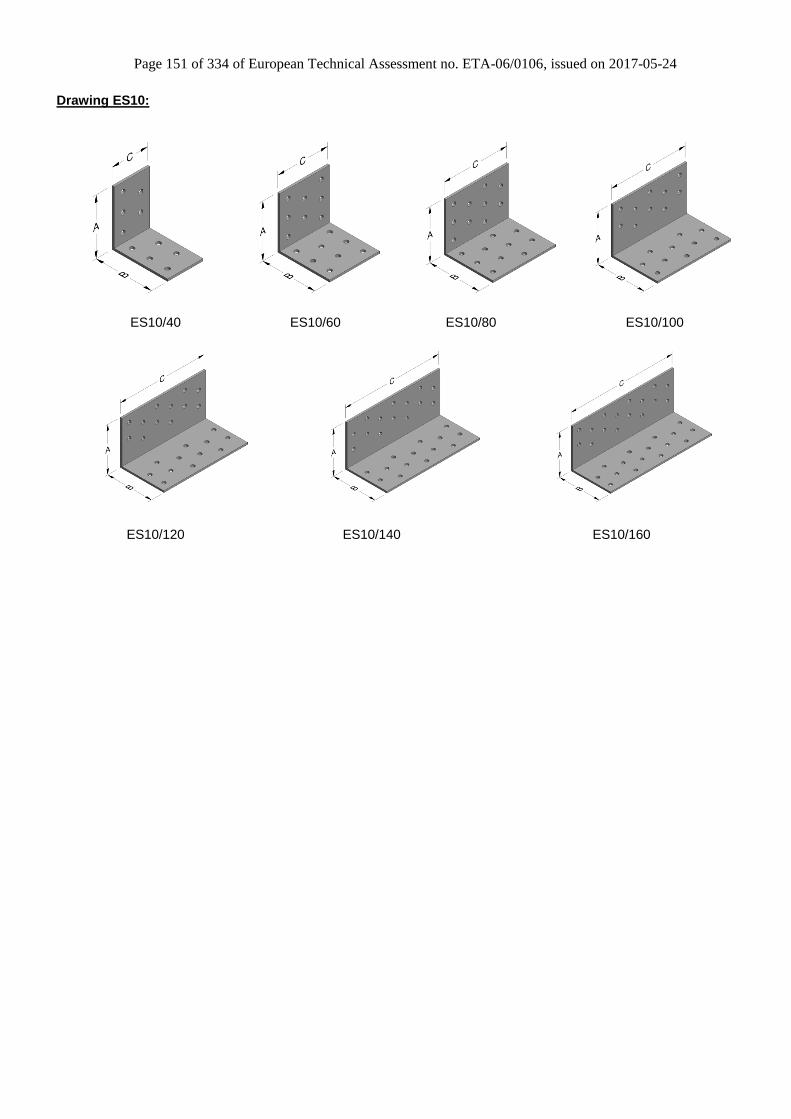
Page 151 of 334 of European Technical Assessment no. ETA-06/0106, issued on 2017-05-24
Drawing ES10:
ES10/40 ES10/60 ES10/80 ES10/100
ES10/120 ES10/140 ES10/160
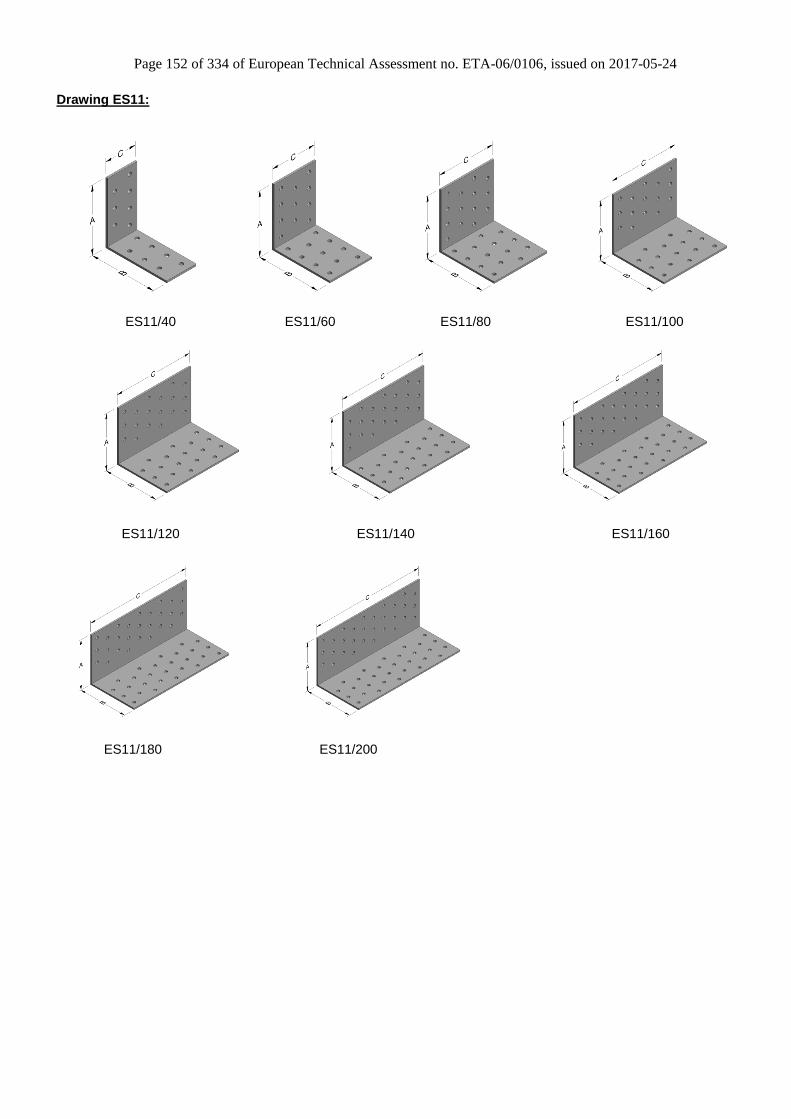
Page 152 of 334 of European Technical Assessment no. ETA-06/0106, issued on 2017-05-24
Drawing ES11:
ES11/40 ES11/60 ES11/80 ES11/100
ES11/120 ES11/140 ES11/160
ES11/180 ES11/200

Page 153 of 334 of European Technical Assessment no. ETA-06/0106, issued on 2017-05-24
Nailing pattern:
Nailing pattern 1 Nailing pattern 2
Flange A:
Flange B:
ES/10/40 to ES10/80 ES10/100 to ES10/160
Beam to Beam
Flange A: Nailing in row no. 3, 4, 5 Flange B: Nailing in row no. 1, 2, 5
Beam to Beam Flange A: Nailing in row no. 2, 3, 4 Flange B: Nailing in row no. 1, 2
Nailing pattern 3 Nailing pattern 4
Flange A:
Flange B:
ES11/40 to ES11/80 ES11/100 to ES11/200
Beam to Beam
Flange A: Nailing in row no. 3, 4, 5, 6, 7 Flange B: Nailing in row no. 1, 2, 5, 6
Beam to Beam Flange A: Nailing in row no. 2, 3, 4, 5, 6 Flange B: Nailing in row no. 1, 2, 5, 6
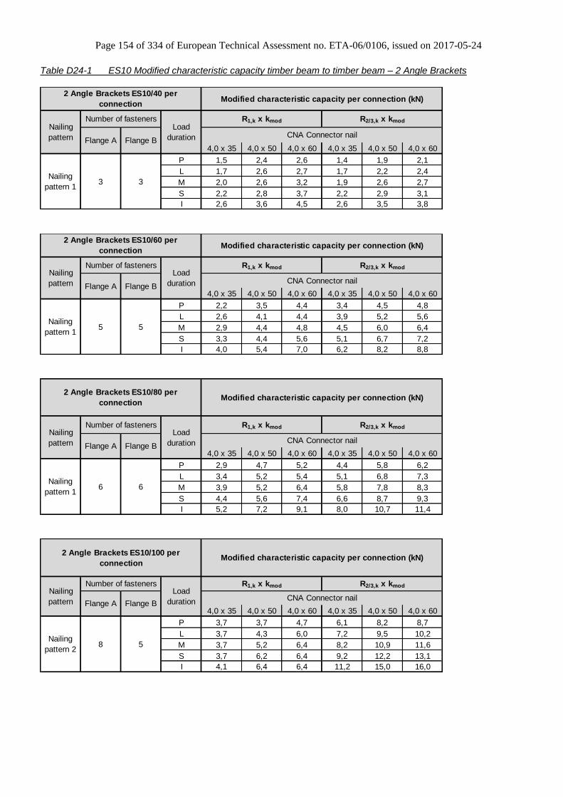
Page 154 of 334 of European Technical Assessment no. ETA-06/0106, issued on 2017-05-24
Table D24-1 ES10 Modified characteristic capacity timber beam to timber beam – 2 Angle Brackets
4,0 x 35 4,0 x 50 4,0 x 60 4,0 x 35 4,0 x 50 4,0 x 60
P 1,5 2,4 2,6 1,4 1,9 2,1
L 1,7 2,6 2,7 1,7 2,2 2,4
M 2,0 2,6 3,2 1,9 2,6 2,7
S 2,2 2,8 3,7 2,2 2,9 3,1
I 2,6 3,6 4,5 2,6 3,5 3,8
Flange B
3 3Nailing
pattern 1
Load
duration
Modified characteristic capacity per connection (kN)
CNA Connector nail
R1,k x kmod R2/3,k x kmod
Nailing
pattern
2 Angle Brackets ES10/40 per
connection
Number of fasteners
Flange A
4,0 x 35 4,0 x 50 4,0 x 60 4,0 x 35 4,0 x 50 4,0 x 60
P 2,2 3,5 4,4 3,4 4,5 4,8
L 2,6 4,1 4,4 3,9 5,2 5,6
M 2,9 4,4 4,8 4,5 6,0 6,4
S 3,3 4,4 5,6 5,1 6,7 7,2
I 4,0 5,4 7,0 6,2 8,2 8,8
Modified characteristic capacity per connection (kN)
CNA Connector nail
R1,k x kmod R2/3,k x kmodNailing
pattern
Number of fasteners
Flange A Flange B
5 5Nailing
pattern 1
2 Angle Brackets ES10/60 per
connection
Load
duration
4,0 x 35 4,0 x 50 4,0 x 60 4,0 x 35 4,0 x 50 4,0 x 60
P 2,9 4,7 5,2 4,4 5,8 6,2
L 3,4 5,2 5,4 5,1 6,8 7,3
M 3,9 5,2 6,4 5,8 7,8 8,3
S 4,4 5,6 7,4 6,6 8,7 9,3
I 5,2 7,2 9,1 8,0 10,7 11,4
Modified characteristic capacity per connection (kN)
CNA Connector nail
R1,k x kmod R2/3,k x kmodNailing
pattern
Number of fasteners
Flange A Flange B
6 6Nailing
pattern 1
2 Angle Brackets ES10/80 per
connection
Load
duration
4,0 x 35 4,0 x 50 4,0 x 60 4,0 x 35 4,0 x 50 4,0 x 60
P 3,7 3,7 4,7 6,1 8,2 8,7
L 3,7 4,3 6,0 7,2 9,5 10,2
M 3,7 5,2 6,4 8,2 10,9 11,6
S 3,7 6,2 6,4 9,2 12,2 13,1
I 4,1 6,4 6,4 11,2 15,0 16,0
Flange B
8 5Nailing
pattern 2
Load
duration
Modified characteristic capacity per connection (kN)
CNA Connector nail
R1,k x kmod R2/3,k x kmod
2 Angle Brackets ES10/100 per
connection
Nailing
pattern
Number of fasteners
Flange A

Page 155 of 334 of European Technical Assessment no. ETA-06/0106, issued on 2017-05-24
4,0 x 35 4,0 x 50 4,0 x 60 4,0 x 35 4,0 x 50 4,0 x 60
P 4,4 4,6 5,8 7,5 10,0 10,6
L 4,6 5,2 7,3 8,7 11,6 12,4
M 4,6 6,4 8,0 10,0 13,3 14,1
S 4,6 7,6 8,0 11,2 14,9 15,9
I 5,1 8,0 8,0 13,7 18,2 19,4
Flange B
9 6Nailing
pattern 2
Load
duration
Modified characteristic capacity per connection (kN)
CNA Connector nail
R1,k x kmod R2/3,k x kmod
2 Angle Brackets ES10/120 per
connection
Nailing
pattern
Number of fasteners
Flange A
4,0 x 35 4,0 x 50 4,0 x 60 4,0 x 35 4,0 x 50 4,0 x 60
P 5,2 5,2 6,7 10,0 13,4 14,2
L 5,2 6,0 8,4 11,7 15,6 16,6
M 5,2 7,4 9,1 13,4 17,8 19,0
S 5,2 8,7 9,1 15,1 20,0 21,4
I 5,8 9,1 9,1 18,4 24,5 26,1
Flange B
10 7Nailing
pattern 2
2 Angle Brackets ES10/140 per
connection
Load
duration
Modified characteristic capacity per connection (kN)
CNA Connector nail
R1,k x kmod R2/3,k x kmod
Nailing
pattern
Number of fasteners
Flange A
4,0 x 35 4,0 x 50 4,0 x 60 4,0 x 35 4,0 x 50 4,0 x 60
P 5,9 6,1 7,7 11,4 15,2 16,2
L 6,1 7,0 9,7 13,3 17,8 18,9
M 6,1 8,5 10,6 15,2 20,3 21,6
S 6,1 10,1 10,6 17,2 22,8 24,3
I 6,8 10,6 10,6 21,0 27,9 29,8
Flange B
12 8Nailing
pattern 2
Load
duration
Modified characteristic capacity per connection (kN)
CNA Connector nail
R1,k x kmod R2/3,k x kmod
2 Angle Brackets ES10/160 per
connection
Nailing
pattern
Number of fasteners
Flange A
Table D24-2 ES11 Modified characteristic capacity timber beam to timber beam – 2 Angle Brackets
4,0 x 35 4,0 x 50 4,0 x 60 4,0 x 35 4,0 x 50 4,0 x 60
P 1,5 2,4 2,6 2,1 2,8 3,0
L 1,7 2,6 2,7 2,5 3,3 3,5
M 2,0 2,6 3,2 2,8 3,7 4,0
S 2,2 2,8 3,7 3,1 4,2 4,5
I 2,6 3,6 4,5 3,8 5,1 5,5
Flange B
5 4Nailing
pattern 3
2 Angle Brackets ES11/40 per
connection
Load
duration
Modified characteristic capacity per connection (kN)
CNA Connector nail
R1,k x kmod R2/3,k x kmodNailing
pattern
Number of fasteners
Flange A

Page 156 of 334 of European Technical Assessment no. ETA-06/0106, issued on 2017-05-24
4,0 x 35 4,0 x 50 4,0 x 60 4,0 x 35 4,0 x 50 4,0 x 60
P 2,2 3,5 4,4 4,4 5,9 6,3
L 2,6 4,1 4,4 5,2 6,9 7,3
M 2,9 4,4 4,8 5,9 7,9 8,4
S 3,3 4,4 5,6 6,7 8,9 9,4
I 4,0 5,4 7,1 8,1 10,8 11,5
Flange B
8 6Nailing
pattern 3
Load
duration
Modified characteristic capacity per connection (kN)
CNA Connector nail
R1,k x kmod R2/3,k x kmod
2 Angle Brackets ES11/60 per
connection
Nailing
pattern
Number of fasteners
Flange A
4,0 x 35 4,0 x 50 4,0 x 60 4,0 x 35 4,0 x 50 4,0 x 60
P 2,9 4,7 5,2 6,1 8,1 8,7
L 3,4 5,2 5,5 7,1 9,5 10,1
M 3,9 5,2 6,5 8,1 10,8 11,5
S 4,4 5,7 7,4 9,1 12,2 13,0
I 5,2 7,2 9,1 11,2 14,9 15,9
Flange B
10 8Nailing
pattern 3
Load
duration
Modified characteristic capacity per connection (kN)
CNA Connector nail
R1,k x kmod R2/3,k x kmod
2 Angle Brackets ES11/80 per
connection
Nailing
pattern
Number of fasteners
Flange A
4,0 x 35 4,0 x 50 4,0 x 60 4,0 x 35 4,0 x 50 4,0 x 60
P 3,7 4,2 5,6 8,8 11,7 12,5
L 3,7 5,1 6,4 10,2 13,6 14,5
M 3,7 6,1 6,4 11,7 15,6 16,6
S 3,8 6,4 6,4 13,2 17,5 18,7
I 5,0 6,4 6,4 16,1 21,4 22,8
Flange B
13 10Nailing
pattern 4
Load
duration
Modified characteristic capacity per connection (kN)
CNA Connector nail
R1,k x kmod R2/3,k x kmod
2 Angle Brackets ES11/100 per
connection
Nailing
pattern
Number of fasteners
Flange A
4,0 x 35 4,0 x 50 4,0 x 60 4,0 x 35 4,0 x 50 4,0 x 60
P 4,4 5,0 6,8 10,4 13,9 14,8
L 4,6 6,2 8,0 12,2 16,2 17,3
M 4,6 7,3 8,0 13,9 18,5 19,8
S 4,6 8,0 8,0 15,7 20,9 22,2
I 6,0 8,0 8,0 19,1 25,5 27,2
Flange B
15 12Nailing
pattern 4
Load
duration
Modified characteristic capacity per connection (kN)
CNA Connector nail
R1,k x kmod R2/3,k x kmod
2 Angle Brackets ES11/120 per
connection
Nailing
pattern
Number of fasteners
Flange A

Page 157 of 334 of European Technical Assessment no. ETA-06/0106, issued on 2017-05-24
4,0 x 35 4,0 x 50 4,0 x 60 4,0 x 35 4,0 x 50 4,0 x 60
P 5,2 5,8 7,8 14,1 18,8 20,0
L 5,2 7,2 9,1 16,5 21,9 23,4
M 5,2 8,6 9,1 18,8 25,0 26,7
S 5,3 9,1 9,1 21,2 28,2 30,0
I 7,0 9,1 9,1 25,9 34,4 36,7
Flange B
17 14Nailing
pattern 4
Load
duration
Modified characteristic capacity per connection (kN)
CNA Connector nail
R1,k x kmod R2/3,k x kmod
2 Angle Brackets ES11/140 per
connection
Nailing
pattern
Number of fasteners
Flange A
4,0 x 35 4,0 x 50 4,0 x 60 4,0 x 35 4,0 x 50 4,0 x 60
P 5,9 6,6 9,0 16,2 21,6 23,0
L 6,1 8,2 10,6 18,9 25,2 26,8
M 6,1 9,8 10,6 21,6 28,7 30,7
S 6,1 10,6 10,6 24,3 32,3 34,5
I 8,0 10,6 10,6 29,7 39,5 42,2
Flange B
20 16Nailing
pattern 4
Load
duration
Modified characteristic capacity per connection (kN)
CNA Connector nail
R1,k x kmod R2/3,k x kmod
2 Angle Brackets ES11/160 per
connection
Nailing
pattern
Number of fasteners
Flange A
4,0 x 35 4,0 x 50 4,0 x 60 4,0 x 35 4,0 x 50 4,0 x 60
P 6,6 7,5 10,1 20,4 27,2 29,1
L 6,7 9,2 11,7 23,9 31,8 33,9
M 6,7 11,0 11,7 27,3 36,3 38,7
S 6,8 11,7 11,7 30,7 40,9 43,6
I 9,0 11,7 11,7 37,5 49,9 53,3
Flange B
23 18Nailing
pattern 4
Load
duration
Modified characteristic capacity per connection (kN)
CNA Connector nail
R1,k x kmod R2/3,k x kmod
2 Angle Brackets ES11/180 per
connection
Nailing
pattern
Number of fasteners
Flange A
4,0 x 35 4,0 x 50 4,0 x 60 4,0 x 35 4,0 x 50 4,0 x 60
P 7,4 8,3 11,2 22,8 30,4 32,4
L 7,6 10,3 13,3 26,7 35,5 37,8
M 7,6 12,2 13,3 30,5 40,6 43,3
S 7,6 13,3 13,3 34,3 45,7 48,7
I 10,0 13,3 13,3 41,9 55,8 59,5
Flange B
25 20Nailing
pattern 4
Load
duration
Modified characteristic capacity per connection (kN)
CNA Connector nail
R1,k x kmod R2/3,k x kmod
2 Angle Brackets ES11/200 per
connection
Nailing
pattern
Number of fasteners
Flange A
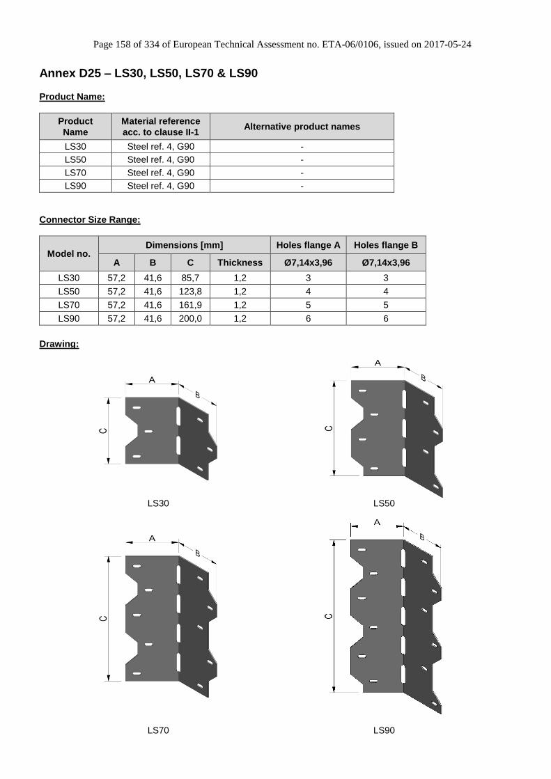
Page 158 of 334 of European Technical Assessment no. ETA-06/0106, issued on 2017-05-24
Annex D25 – LS30, LS50, LS70 & LS90
Product Name:
Product
Name
Material reference
acc. to clause II-1 Alternative product names
LS30 Steel ref. 4, G90 -
LS50 Steel ref. 4, G90 -
LS70 Steel ref. 4, G90 -
LS90 Steel ref. 4, G90 -
Connector Size Range:
Model no. Dimensions [mm] Holes flange A Holes flange B
A B C Thickness Ø7,14x3,96 Ø7,14x3,96
LS30 57,2 41,6 85,7 1,2 3 3
LS50 57,2 41,6 123,8 1,2 4 4
LS70 57,2 41,6 161,9 1,2 5 5
LS90 57,2 41,6 200,0 1,2 6 6
Drawing:
LS30 LS50
LS70 LS90

Page 159 of 334 of European Technical Assessment no. ETA-06/0106, issued on 2017-05-24
Nailing pattern:
Nailing pattern 1 Nailing pattern 2 Nailing pattern 3
Flange A:
Flange
B:
LS30
Beam to Beam Full nailing
LS50 Beam to Beam
Full nailing
LS70 Beam to Beam
Full nailing
Nailing pattern 4
Flange A:
Flange B:
LS90
Beam to Beam Full nailing
Design Basis:
One angle bracket per connection
Acting forces
F2=F3 The force is acting in the bending line of the
angle bracket and parallel to it.
F2=F3
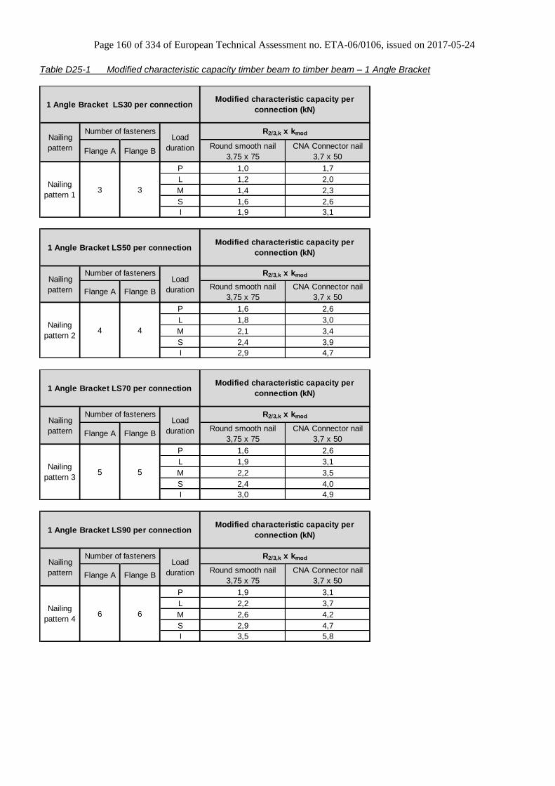
Page 160 of 334 of European Technical Assessment no. ETA-06/0106, issued on 2017-05-24
Table D25-1 Modified characteristic capacity timber beam to timber beam – 1 Angle Bracket
Round smooth nail CNA Connector nail
3,75 x 75 3,7 x 50
P 1,0 1,7
L 1,2 2,0
M 1,4 2,3
S 1,6 2,6
I 1,9 3,1
3
Load
duration
Modified characteristic capacity per
connection (kN)
R2/3,k x kmodNailing
pattern
1 Angle Bracket LS30 per connection
Nailing
pattern 1
Number of fasteners
Flange A Flange B
3
Round smooth nail CNA Connector nail
3,75 x 75 3,7 x 50
P 1,6 2,6
L 1,8 3,0
M 2,1 3,4
S 2,4 3,9
I 2,9 4,7
4
Load
duration
Modified characteristic capacity per
connection (kN)
R2/3,k x kmod
1 Angle Bracket LS50 per connection
Nailing
pattern
Nailing
pattern 2
Number of fasteners
Flange A Flange B
4
Round smooth nail CNA Connector nail
3,75 x 75 3,7 x 50
P 1,6 2,6
L 1,9 3,1
M 2,2 3,5
S 2,4 4,0
I 3,0 4,9
5
Load
duration
Modified characteristic capacity per
connection (kN)
R2/3,k x kmod
1 Angle Bracket LS70 per connection
Nailing
pattern
Nailing
pattern 3
Number of fasteners
Flange A Flange B
5
Round smooth nail CNA Connector nail
3,75 x 75 3,7 x 50
P 1,9 3,1
L 2,2 3,7
M 2,6 4,2
S 2,9 4,7
I 3,5 5,8
6
Load
duration
Modified characteristic capacity per
connection (kN)
R2/3,k x kmod
1 Angle Bracket LS90 per connection
Nailing
pattern
Nailing
pattern 4
Number of fasteners
Flange A Flange B
6

Page 161 of 334 of European Technical Assessment no. ETA-06/0106, issued on 2017-05-24
Annex D26 – TA9Z & TA10Z
Product Name:
Product
Name
Material reference
acc. to clause II-1 Alternative product names
TA9Z Steel ref. 4, G185 -
TA10Z Steel ref. 4, G185 -
Connector Size Range:
Model no. Dimensions [mm] Holes flange A Holes flange B
A B C Thickness Ø7 Ø7
TA9Z 41 41 210 2,5 3 2
TA10Z 41 41 260 2,5 4 3
Drawing:
TA9Z TA10Z

Page 162 of 334 of European Technical Assessment no. ETA-06/0106, issued on 2017-05-24
Nailing pattern:
Nailing pattern 1 Nailing pattern 2
Flange A:
Flange B:
TA9Z
Beam to Beam TA10Z
Beam to Beam
Design basis:
Typical installation – Design basis
Table D26-1 Modified characteristic capacity timber beam to timber beam – 1 angle bracket
Modified characteristic capacity per
connection (kN)
R1,k x kmod
P 3,8
L 4,5
M 5,2
S 5,9
I 7,3
P 5,1
L 6,0
M 6,9
S 7,9
I 9,7
Smooth shank screws 6,0 x 45 in pre-
drilled holes
TA9Z
TA10Z
Type
1 Angle Bracket per connection
Nailing
pattern 13 2
Nailing
pattern 24 3
Nailing
pattern
Number of fastenersLoad
durationFlange A Flange B
One angle bracket per connection Acting forces F1 Downward force from the step acting close to the string
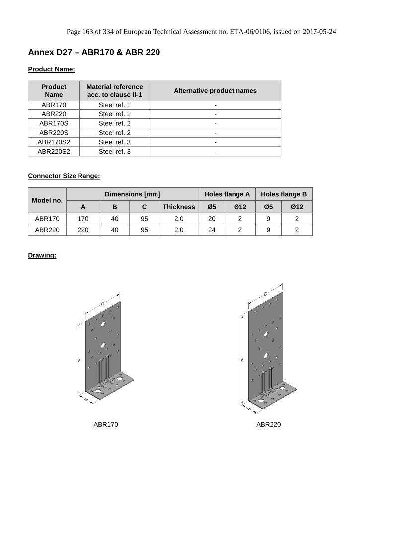
Page 163 of 334 of European Technical Assessment no. ETA-06/0106, issued on 2017-05-24
Annex D27 – ABR170 & ABR 220
Product Name:
Product
Name
Material reference
acc. to clause II-1 Alternative product names
ABR170 Steel ref. 1 -
ABR220 Steel ref. 1 -
ABR170S Steel ref. 2 -
ABR220S Steel ref. 2 -
ABR170S2 Steel ref. 3 -
ABR220S2 Steel ref. 3 -
Connector Size Range:
Model no. Dimensions [mm] Holes flange A Holes flange B
A B C Thickness Ø5 Ø12 Ø5 Ø12
ABR170 170 40 95 2,0 20 2 9 2
ABR220 220 40 95 2,0 24 2 9 2
Drawing:
ABR170 ABR220
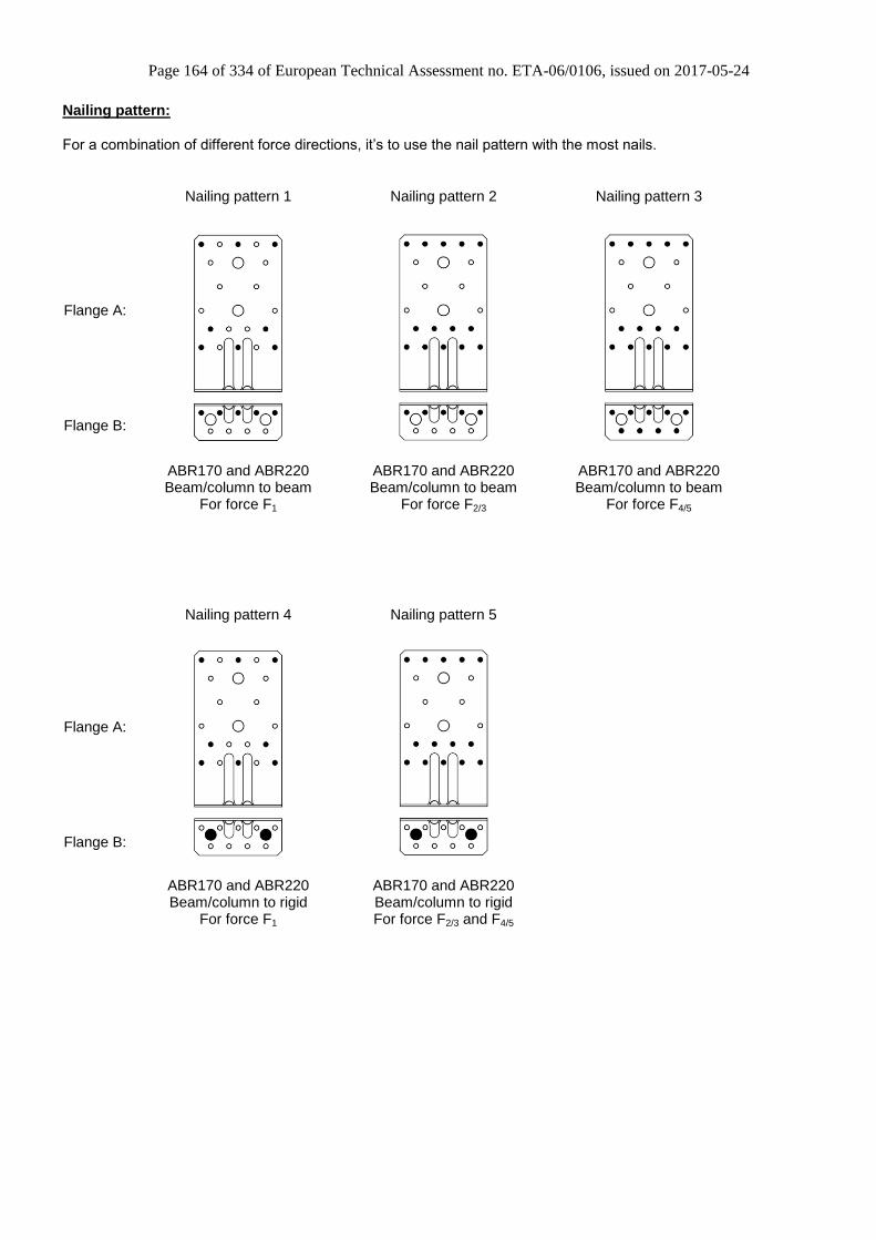
Page 164 of 334 of European Technical Assessment no. ETA-06/0106, issued on 2017-05-24
Nailing pattern:
For a combination of different force directions, it’s to use the nail pattern with the most nails.
Nailing pattern 1 Nailing pattern 2 Nailing pattern 3
Flange A:
Flange B:
ABR170 and ABR220 Beam/column to beam
For force F1
ABR170 and ABR220 Beam/column to beam
For force F2/3
ABR170 and ABR220 Beam/column to beam
For force F4/5
Nailing pattern 4 Nailing pattern 5
Flange A:
Flange B:
ABR170 and ABR220 Beam/column to rigid
For force F1
ABR170 and ABR220 Beam/column to rigid For force F2/3 and F4/5

Page 165 of 334 of European Technical Assessment no. ETA-06/0106, issued on 2017-05-24
Table D27-1 Modified characteristic capacity timber beam/column to timber beam – 2 Angle Brackets Load duration
M
Flange A Flange B 4,0x40 4,0x50 4,0x60
Nailing
pattern 18 5 R1,k x kmod 5,9 7,8 9,8
Nailing
pattern 214 5 R2/3,k x kmod 13,1 15,8 16,9
Nailing
pattern 314 9 R4/5,k x kmod
8,0
with
e ≤ 50 mm
b ≥ 36 mm
or
e ≤ 90 mm
b ≥ 60 mm
8,0
with
e ≤ 65 mm
b ≥ 36 mm
or
e ≤ 120 mm
b ≥ 60 mm
8,0
with
e ≤ 80 mm
b ≥ 36 mm
or
e ≤ 150 mm
b ≥ 60 mm
Load
duration
M
Number of fasteners CNA Connector nailNailing
pattern
2 Angle Brackets
ABR170 or ABR220
per connection
Modified characteristic capacity per connection (kN)
Table D27-2 Modified characteristic capacity timber beam/column to timber beam – 1 Angle Bracket Load duration
M
Flange A Flange B 4,0x40 4,0x50 4,0x60
Nailing
pattern 18 5 R1,k x kmod 2,9 3,9 4,9
Nailing
pattern 214 5 R2/3,k x kmod 6,6 7,9 8,5
Nailing
pattern 314 9 R4,k x kmod
0,7
with
e ≤ 50 mm
0,7
with
e ≤ 50 mm
0,7
with
e ≤ 50 mm
Nailing
pattern 314 9 R4,k x kmod
Nailing
pattern 314 9 R5,k x kmod
1,4
with
e ≤ 50 mm
b ≥ 36 mm
or
e ≤ 90 mm
b ≥ 60 mm
1,4
with
e ≤ 65 mm
b ≥ 36 mm
or
e ≤ 120 mm
b ≥ 60 mm
1,4
with
e ≤ 80 mm
b ≥ 36 mm
or
e ≤ 150 mm
b ≥ 60 mm
1 Angle Bracket
ABR170 or ABR220
per connection
Nailing
pattern
Load
duration
Modified characteristic capacity per connection (kN)
M
Number of fasteners CNA Connector nail
Capacity for a connection,
witout rotation of purlin:
6,6

Page 166 of 334 of European Technical Assessment no. ETA-06/0106, issued on 2017-05-24
Factors for other Load durations:
R2/3,k R4,k R4,k 1) R5,k R4/5,k
4,0x40 4,0x50 4,0x60
I multiply M by 1,38 1,33 1,23 1,38 1 1,38 1 1,31
S multiply M by 1,13 1,13 1,08 1,13 1 1,13 1 1,1
L multiply M by 0,88 0,88 0,88 0,88 1 0,88 1 0,9
P multiply M by 0,75 0,75 0,75 0,75 1 0,75 1 0,79
1) capacity for a connection, witout rotation of purlin
All sizes
Factors for
other
load durations
R1,k
CNA Connector nail
Table D27-3 Characteristic capacity timber beam/column to rigid – 2 Angle Brackets
Flange A Flange B 4,0x40 4,0x50 4,0x60
Nailing
pattern 48 2 Bolts R1,k
Nailing
pattern 514 2 Bolts R2/3,k 19,71
Nailing
pattern 514 2 Bolts R4/5,k
the minimum of
e is 50 mm
CNA Connector nailNailing
pattern
Number of fasteners
Characteristic capacity per connection (kN)
2 Angle Brackets
ABR170 or ABR220
per connection
mod
2,25
0,33
min
k
mod
2,25
8,39
min
k mod
2,25
k
mod
6,24
8,23
min
k
mod
6,24
4,25
min
k
mod
mod
3,6
8015,9
min
ke
b
ke
For connection with 2 Angle Brackets it must be checked:
for R1: Rbolt,ax,d ≥ F1,d / nbolt
for R2/3: Rbolt,lat,d ≥ F2/3,d / nbolt
for R4/5 : Bolt 1: Rbolt,ax,d ≥ F4/5,d x e / (2xb)
Bolt 2: Rbolt,lat,d ≥ F4/5,d / 2
R4/5,d ≤ R1,d x b / (2 x e)
In case of combined force the relevant of the following inequalities shall be fulfilled:
For F4/5 can be use also F4 or F5 too, also for F2/3 can be use F2 or F3 too.
1,3,2
,3/2
2
,5/4
,5/4
,1
,1
d
d
d
d
d
d
R
F
R
F
R
F
4/5F
5F
4F
e
e <
50m
me
b
b
F3
2F
F1
3F
F1
F2
1F
2F
bolt 2bolt 1
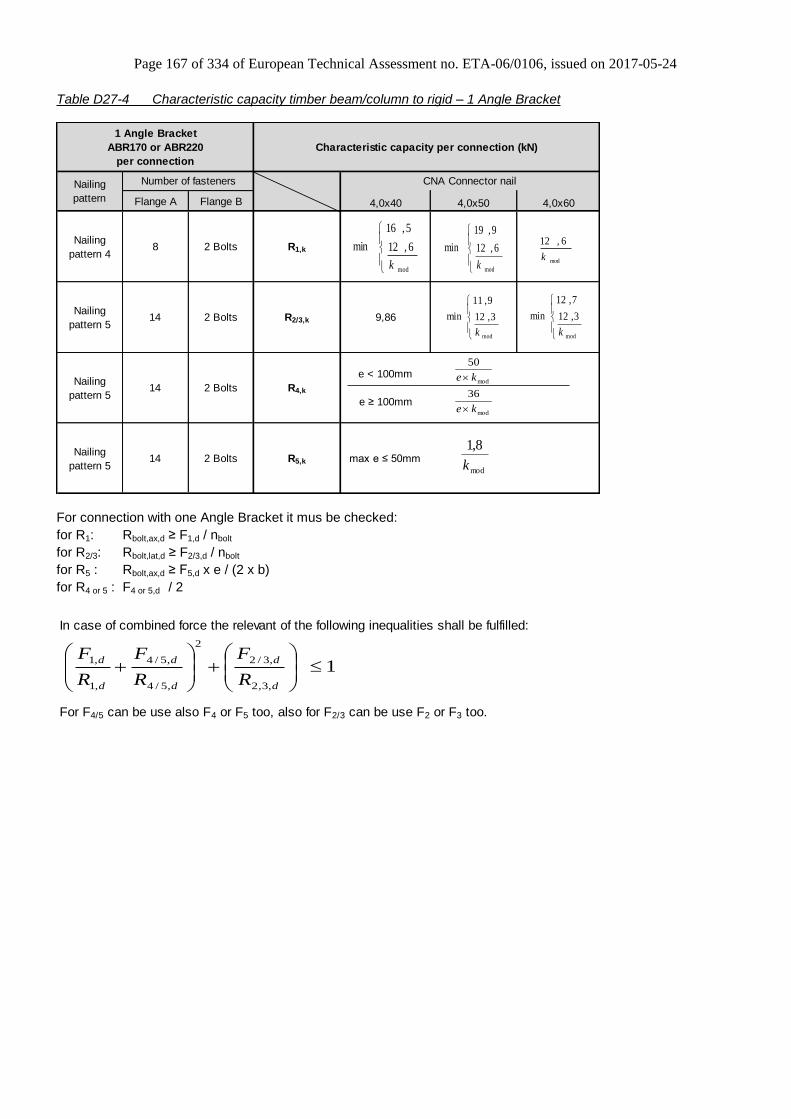
Page 167 of 334 of European Technical Assessment no. ETA-06/0106, issued on 2017-05-24
Table D27-4 Characteristic capacity timber beam/column to rigid – 1 Angle Bracket
Flange A Flange B 4,0x40 4,0x50 4,0x60
Nailing
pattern 48 2 Bolts R1,k
Nailing
pattern 514 2 Bolts R2/3,k 9,86
Nailing
pattern 514 2 Bolts R4,k
e < 100mm
e ≥ 100mm
Nailing
pattern 514 2 Bolts R5,k max e ≤ 50mm
CNA Connector nail
1 Angle Bracket
ABR170 or ABR220
per connection
Number of fastenersNailing
pattern
Characteristic capacity per connection (kN)
mod
mod
36
50
ke
ke
mod
6,12
5,16
min
k
mod
6,12
9,19
min
kmod
6,12
k
mod
3,12
9,11
min
k
mod
3,12
7,12
min
k
mod
8,1
k
For connection with one Angle Bracket it mus be checked:
for R1: Rbolt,ax,d ≥ F1,d / nbolt
for R2/3: Rbolt,lat,d ≥ F2/3,d / nbolt
for R5 : Rbolt,ax,d ≥ F5,d x e / (2 x b)
for R4 or 5 : F4 or 5,d / 2
In case of combined force the relevant of the following inequalities shall be fulfilled:
For F4/5 can be use also F4 or F5 too, also for F2/3 can be use F2 or F3 too.
1,3,2
,3/2
2
,5/4
,5/4
,1
,1
d
d
d
d
d
d
R
F
R
F
R
F

Page 168 of 334 of European Technical Assessment no. ETA-06/0106, issued on 2017-05-24
Annex D28 – AB6983
Product Name:
Product
Name
Material reference
acc. to clause II-1 Alternative product names
AB6983 Steel ref. 1 -
AB6983S Steel ref. 2 -
AB6983S2 Steel ref. 3 -
Connector Size Range:
Model no. Dimensions [mm] Holes flange A Holes flange B
A B C Thickness Ø4 Ø13
AB6983 69 83 300 2,5 14 2
Drawing:
Nailing pattern:
Nailing pattern 1
Flange A:
Flange B:
Timber to rigid

Page 169 of 334 of European Technical Assessment no. ETA-06/0106, issued on 2017-05-24
Modified characteristic capacity per connection (one shear connector per connection):
14,2
29,9min
..
mod..
mod3/2
kboltlat
knaillat
R
kRkxR
The capacity of the connection between the bolts and concrete has to be checked separately
Fasteners: 14 threaded nails CNA3,1xℓ and 2 bolts Ø12 mm. (Nailing pattern 1)
knaillatR ,, = Characteristic lateral capacity of 1 threaded nail CNA3,1xℓ
kboltlatR ,, = Characteristic lateral capacity of 1 M12 bolt. max. 7,5 kN
modk = Strength modification factor for service class and load-duration class according to Eurocode 5.
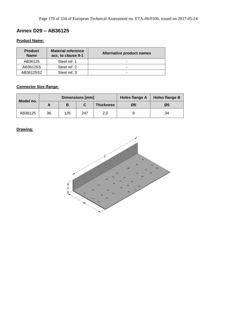
Page 170 of 334 of European Technical Assessment no. ETA-06/0106, issued on 2017-05-24
Annex D29 – AB36125
Product Name:
Product
Name
Material reference
acc. to clause II-1 Alternative product names
AB36125 Steel ref. 1 -
AB36125S Steel ref. 2 -
AB36125S2 Steel ref. 3 -
Connector Size Range:
Model no. Dimensions [mm] Holes flange A Holes flange B
A B C Thickness Ø5 Ø5
AB36125 36 125 247 2,0 9 34
Drawing:
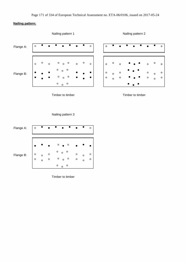
Page 171 of 334 of European Technical Assessment no. ETA-06/0106, issued on 2017-05-24
Nailing pattern:
Nailing pattern 1 Nailing pattern 2
Flange A:
Flange B:
Timber to timber Timber to timber
Nailing pattern 3
Flange A:
Flange B:
Timber to timber

Page 172 of 334 of European Technical Assessment no. ETA-06/0106, issued on 2017-05-24
Modified characteristic capacity per connection (one shear connector per connection):
Fasteners: 7 + 12 (Nailing pattern 1):
mod,,
mod,,
mod3/257,8
60,5min
kR
kRkR
khnaillat
kvnaillat
Fasteners: 7 + 12 (Nailing pattern 2):
mod,,
mod,,
mod3/204,6
60,5min
kR
kRkR
khnaillat
kvnaillat
Fasteners: 7 + 7 (Nailing pattern 3):
mod,,
mod,,
mod3/212,6
60,5min
kR
kRkR
khnaillat
kvnaillat
Rlat,nail-v,k = Characteristic lateral capacity of 1 threaded nail CNA4,0xℓ in the vertical flange
Rlat,nail-h,k = Characteristic lateral capacity of 1 threaded nail CNA4,0xℓ in the horizontal flange
kmod = Strength modification factor for service class and load-duration class according to Eurocode 5.

Page 173 of 334 of European Technical Assessment no. ETA-06/0106, issued on 2017-05-24
Annex D30 – BNV33
Product Name:
Product
Name
Material reference
acc. to clause II-1 Alternative product names
BNV33 Steel ref. 1 -
BNV33S Steel ref. 2 -
BNV33S2 Steel ref. 3 -
Connector Size Range:
Model no. Dimensions [mm] Holes flange A Holes flange B
A B C Thickness Ø5 Ø8,5 Ø11 Ø5 Ø8,5 Ø13
BNV33 62,5 34,5 180 1,5 13 6 2 7 4 2
Drawing:
Nailing pattern:
Nailing pattern 1 Nailing pattern 2
Flange A:
Flange B:
Timber to timber Timber to rigid

Page 174 of 334 of European Technical Assessment no. ETA-06/0106, issued on 2017-05-24
Modified characteristic capacity per connection (one shear connector per connection):
Fasteners: 9+7 (Nailing pattern 1):
mod,,
mod,,
mod3/226,6
82,5min
kR
kRkR
khnaillat
kvnaillat
Fasteners: 9+2 (Nailing pattern 2)
mod,,
mod,,
mod3/224,2
82,5min
kR
kRkR
kboltlat
knaillat
The capacity of the connection between the bolts and concrete has to be checked separately
Rlat,nail-v,k = Characteristic lateral capacity of 1 threaded nail CNA4,0xℓ in the vertical flange
Rlat,nail-h,k = Characteristic lateral capacity of 1 threaded nail CNA4,0xℓ in the horizontal flange
Rlat,nail,k = Characteristic lateral capacity of 1 threaded nail CNA4,0xℓ
Rlat,bolt,k = Characteristic lateral capacity of 1 M12 bolt, max. 4,5 kN
kmod = Strength modification factor for service class and load-duration class according to Eurocode 5.
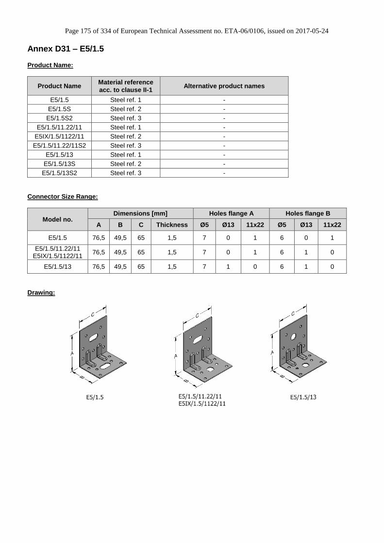
Page 175 of 334 of European Technical Assessment no. ETA-06/0106, issued on 2017-05-24
Annex D31 – E5/1.5
Product Name:
Product Name Material reference
acc. to clause II-1 Alternative product names
E5/1.5 Steel ref. 1 -
E5/1.5S Steel ref. 2 -
E5/1.5S2 Steel ref. 3 -
E5/1.5/11.22/11 Steel ref. 1 -
E5IX/1.5/1122/11 Steel ref. 2 -
E5/1.5/11.22/11S2 Steel ref. 3 -
E5/1.5/13 Steel ref. 1 -
E5/1.5/13S Steel ref. 2 -
E5/1.5/13S2 Steel ref. 3 -
Connector Size Range:
Model no. Dimensions [mm] Holes flange A Holes flange B
A B C Thickness Ø5 Ø13 11x22 Ø5 Ø13 11x22
E5/1.5 76,5 49,5 65 1,5 7 0 1 6 0 1
E5/1.5/11.22/11 E5IX/1.5/1122/11
76,5 49,5 65 1,5 7 0 1 6 1 0
E5/1.5/13 76,5 49,5 65 1,5 7 1 0 6 1 0
Drawing:
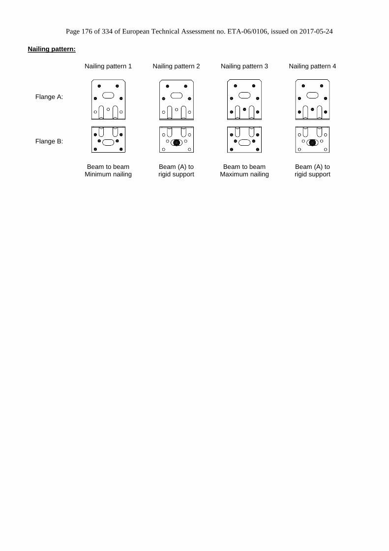
Page 176 of 334 of European Technical Assessment no. ETA-06/0106, issued on 2017-05-24
Nailing pattern:
Nailing pattern 1 Nailing pattern 2 Nailing pattern 3 Nailing pattern 4
Flange A:
Flange B:
Beam to beam
Minimum nailing Beam (A) to rigid support
Beam to beam Maximum nailing
Beam (A) to rigid support

Page 177 of 334 of European Technical Assessment no. ETA-06/0106, issued on 2017-05-24
Table D31-1 Modified characteristic capacity timber beam to timber beam – 1 Angle Bracket E5/1.5 &
E5/1.5/11.22/11 & E5IX/1.5/1122/11, Nailing pattern 1
Flange A Flange B 4,0x35 4,0x60 4,0x35 4,0x60
Min of Min of
f ≤ 6,7 f ≤ 3,3 20/(e - 1,5) 20/(e - 1,5)
23/√(e² + 25)
f > 6,7 f > 3,3 3,6 3,6
7,4/(e - 26) 7,4/(e - 26)
Min of Min of
f ≤ 5,5 f ≤ 2,7 20/(e - 1,5) 20/(e - 1,5)
28/√(e² + 25)
f > 5,5 f > 2,7 4 4
7,4/(e - 26) 7,4/(e - 26)
Min of Min of
f ≤ 4,6 f ≤ 2,2 20/(e - 1,5) 20/(e - 1,5)
32/√(e² + 25)
f > 4,6 f > 2,2 4,1 4,1
7,4/(e - 26) 7,4/(e - 26)
Min of Min of
f ≤ 3,9 f ≤ 1,9 20/(e - 1,5) 20/(e - 1,5)
36/√(e² + 25)
f > 3,9 f > 1,9 4,4 4,4
7,4/(e - 26) 7,4/(e - 26)
Min of Min of
f ≤ 3 f ≤ 1,4 20/(e - 1,5) 20/(e - 1,5)
44/√(e² + 25)
f > 3 f > 1,4 4,9 4,9
7,4/(e - 26) 7,4/(e - 26)
Nailing
pattern1
Nailing
pattern
Number of fasteners
1 Angle Bracket per connection
4 6
R1,k x kmod
I
4 / ( f + 1)
P
L
1,5
33 / ( f + 46 ) 67 / ( f + 46 )
4 / ( f + 1) 4 / ( f + 1)
Modified characteristic capacity per connection (kN)
R2/3,k x kmod R4,k x kmod
28 / ( f + 46 )
M
S
2,7
4,0x60
1,7
2
4 / ( f + 1)
Load
duration
4,652 / ( f + 46 ) 105 / ( f + 46 )
4 / ( f + 1) 4 / ( f + 1)
2,9
3,338 / ( f + 46 ) 76 / ( f + 46 )
4 / ( f + 1)
2,557 / ( f + 46 )
4 / ( f + 1)
4,0x35
2,2 3,843 / ( f + 46 ) 86 / ( f + 46 )
4 / ( f + 1) 4 / ( f + 1)
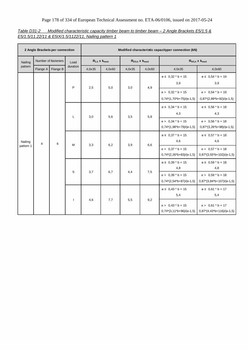
Page 178 of 334 of European Technical Assessment no. ETA-06/0106, issued on 2017-05-24
Table D31-2 Modified characteristic capacity timber beam to timber beam – 2 Angle Brackets E5/1.5 &
E5/1.5/11.22/11 & E5IX/1.5/1122/11, Nailing pattern 1
Flange A Flange B 4,0x35 4,0x60 4,0x35 4,0x60
e ≤ 0,32 * b + 15 e ≤ 0,54 * b + 19
e > 0,32 * b + 15 e > 0,54 * b + 19
e ≤ 0,34 * b + 15 e ≤ 0,56 * b + 18
e > 0,34 * b + 15 e > 0,56 * b + 18
e ≤ 0,37 * b + 15 e ≤ 0,57 * b + 18
e > 0,37 * b + 15 e > 0,57 * b + 18
e ≤ 0,39 * b + 15 e ≤ 0,59 * b + 18
e > 0,39 * b + 15 e > 0,59 * b + 18
e ≤ 0,43 * b + 15 e ≤ 0,61 * b + 17
e > 0,43 * b + 15 e > 0,61 * b + 17
S
I
Modified characteristic capacity per connection (kN)2 Angle Brackets per connection
R1,k x kmod R2/3,k x kmod R4/5,k x kmodNailing
pattern
Number of fasteners Load
duration
Nailing
pattern 14
0,74*(1,70*b+75)/(e-1,5) 0,87*(2,89*b+92)/(e-1,5)
2,5 5,0 3,0 4,9
3,9 3,9
5,84,3 4,3
0,74*(1,98*b+79)/(e-1,5) 0,87*(3,26*b+98)/(e-1,5)
3,0 5,6 3,5
3,3 6,2 3,9 6,6
4,66
P
L
M
4,6
0,74*(2,26*b+83)/(e-1,5) 0,87*(3,55*b+102)/(e-1,5)
3,7 6,7 4,4 7,5
4,8 4,8
7,7 5,5 9,2
5,4 5,4
0,74*(3,11*b+96)/(e-1,5)
4,0x35 4,0x60
0,87*(4,43*b+116)/(e-1,5)
0,74*(2,54*b+87)/(e-1,5) 0,87*(3,84*b+107)/(e-1,5)
4,6

Page 179 of 334 of European Technical Assessment no. ETA-06/0106, issued on 2017-05-24
Table D31-3 Modified characteristic capacity timber beam to rigid support – 1 Angle Bracket E5/1.5 &
E5/1.5/11.22/11 & E5IX/1.5/1122/11, Nailing pattern 2
Flange A Flange B 4,0x35 4,0x60 4,0x35 4,0x60
P 0,6 1,1
L 0,8 1,3
M 0,9 1,5
S 1,1 1,7
I 1,2 2,1
1 Angle Bracket per connection
Number of fasteners R2/3,k x kmod R4,k x kmod
Min of
12,1 / (f + 24)
4,1 / f
Min of
36,3 / e
8 / (e - 26)
12,9
Nailing
pattern
Nailing
pattern 2
Load
duration
1 x Ø10
Bolt4
R1,k x kmod
4,0x35 4,0x60
Modified characteristic capacity per connection (kN)
Note: For R4,k if the purlin is prevented from rotation, consider the value given for two brackets for e=0.
Bolt factor for F1 for F2/3 for F4
kax (f+38)/8 0,46 e/8
klat - 1,0 1,0
For each bolt it´s needed to check: Rbolt,d,lateral ≥ klat x Fi,d ; Rbolt,d,axial ≥ kax x Fi,d ; and also the combination

Page 180 of 334 of European Technical Assessment no. ETA-06/0106, issued on 2017-05-24
Table D31-4 Modified characteristic capacity timber beam to rigid support – 2 Angle Brackets E5/1.5 &
E5/1.5/11.22/11 & E5IX/1.5/1122/11, Nailing pattern 2
Flange A Flange B 4,0x35 4,0x60 4,0x35 4,0x60
e ≤ 0,26 * b + 21 e ≤ 0,42* b + 25
e > 0,26 * b + 21 e > 0,42* b + 25
e ≤ 0,28 * b + 20 e ≤ 0,46 * b + 25
e > 0,28 * b + 20 e > 0,46 * b + 25
e ≤ 0,30 * b + 20 e ≤ 0,49 * b + 25
e > 0,30 * b + 20 e > 0,49 * b + 25
e ≤ 0,31 * b + 20 e ≤ 0,52 * b + 25
e > 0,31 * b + 20 e > 0,52 * b + 25
e ≤ 0,35 * b + 20 e ≤ 0,57 * b + 26
e > 0,35 * b + 20 e > 0,57 * b + 26
Nailing
pattern
Number of fasteners Load
duration
1 x Bolt
Ø10
P
L
M
S
I
Modified characteristic capacity per connection (kN)2 Angle Brackets per connection
Nailing
pattern 24
R1,k x kmod R2/3,k x kmod R4/5,k x kmod
4,4
4,0x35 4,0x60
2,3 4,4 1,3 2,0
4,4
0,74*(1,54*b+107)/(e-1,5) 0,87*(2,53*b+132)/(e-1,5)
2,7 5,1 1,6 2,64,8 4,8
0,74*(1,80*b+114)/(e-1,5) 0,87*(2,96*b+143)/(e-1,5)
3,0 5,5 1,8 3,0
5,1 5,1
0,74*(2,05*b+120)/(e-1,5) 0,87*(3,38*b+153)/(e-1,5)
3,4 5,5 2,1 3,3
5,5 5,5
0,74*(2,31*b+126)/(e-1,5) 0,87*(3,80*b+154)/(e-1,5)
6,0
0,74*(2,82*b+139)/(e-1,5) 0,87*(4,65*b+185)/(e-1,5)
4,1 5,5 2,5 4,1
6,0
Note: Value given for a withdrawal characteristic capacity of the bolt of 16 kN. For others bolt withdrawal capacities
Rk,anchor (kN), value must be limited by 13.6 * Rk,anchor / 16
Bolt factor for F1 for F2/3 for F4/5, bolt 1 for F4/5, bolt 2
kax 0,98 0,23 1,96 x e / (b + 25) -
klat - 0,50 - 1,00
For each bolt it´s needed to check: Rbolt,d,lateral ≥ klat x Fi,d ; Rbolt,d,axial ≥ kax x Fi,d ; and also the combination

Page 181 of 334 of European Technical Assessment no. ETA-06/0106, issued on 2017-05-24
Table D31-5 Modified characteristic capacity timber beam to rigid support – 1 Angle Bracket, Nailing pattern 2
Flange A Flange B 4,0x35 4,0x60 4,0x35 4,0x60
P 0,6 1
L 0,8 1,3
M 0,9 1,5
S 1,1 1,7
I 1,2 2,1
Min of
13,6 / (f + 23)
5,2 / f
Min of
36,3 / e
8 / (e - 26)
19,3
Load
duration
Modified characteristic capacity per connection (kN)
R1,k x kmod R2/3,k x kmod R4,k x kmod
4,0x35 4,0x60
Nailing
pattern 2
Nailing
pattern
Number of fasteners
1 Angle Bracket E5/1.5/13 per connection
41 x Ø10
Bolt
Note: For R4,k if the purlin is prevented from rotation, consider the value given for two brackets for e=0.
Bolt factor for F1 for F2/3 for F4
kax (f + 38) / 8 0,46 e / 8
klat - 1,0 1,0
For each bolt it´s needed to check: Rbolt,d,lateral ≥ klat x Fi,d ; Rbolt,d,axial ≥ kax x Fi,d ; and also the combination
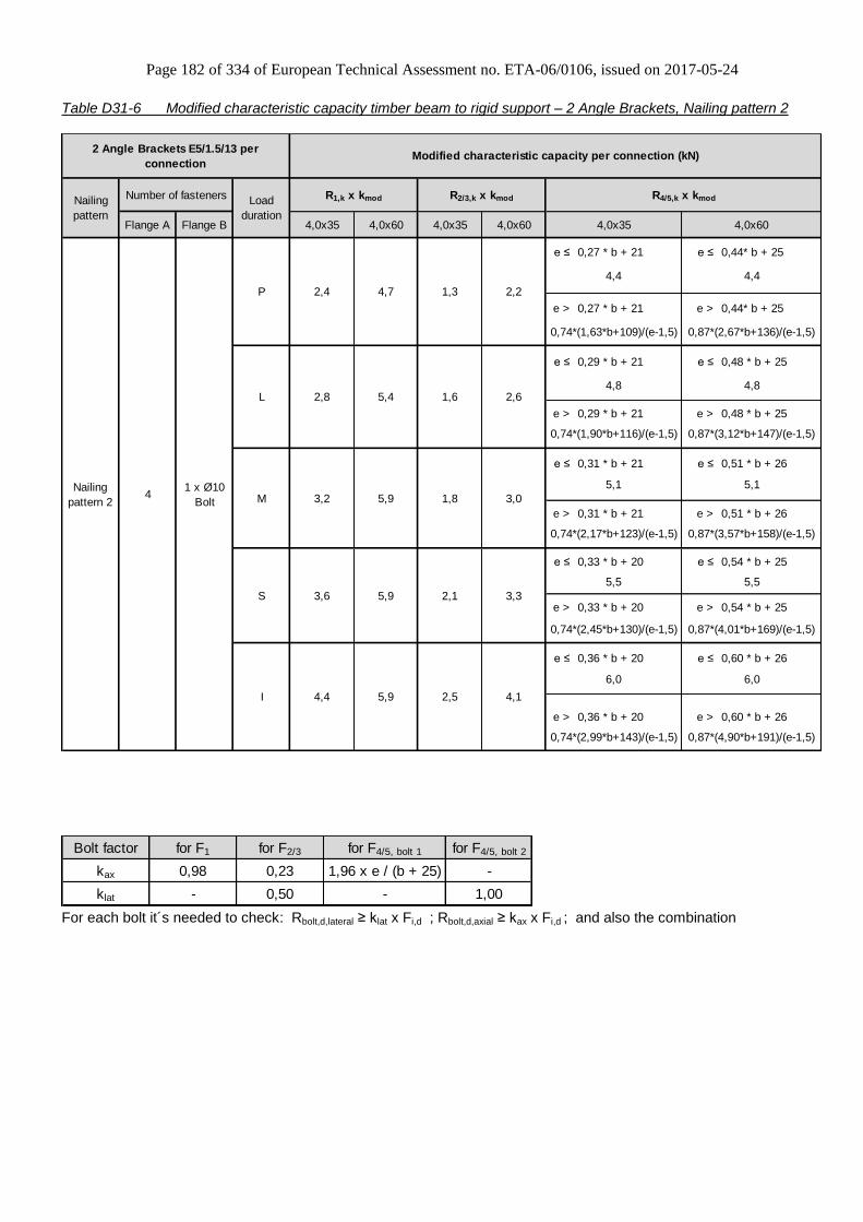
Page 182 of 334 of European Technical Assessment no. ETA-06/0106, issued on 2017-05-24
Table D31-6 Modified characteristic capacity timber beam to rigid support – 2 Angle Brackets, Nailing pattern 2
Flange A Flange B 4,0x35 4,0x60 4,0x35 4,0x60
e ≤ 0,27 * b + 21 e ≤ 0,44* b + 25
e > 0,27 * b + 21 e > 0,44* b + 25
e ≤ 0,29 * b + 21 e ≤ 0,48 * b + 25
e > 0,29 * b + 21 e > 0,48 * b + 25
e ≤ 0,31 * b + 21 e ≤ 0,51 * b + 26
e > 0,31 * b + 21 e > 0,51 * b + 26
e ≤ 0,33 * b + 20 e ≤ 0,54 * b + 25
e > 0,33 * b + 20 e > 0,54 * b + 25
e ≤ 0,36 * b + 20 e ≤ 0,60 * b + 26
e > 0,36 * b + 20 e > 0,60 * b + 26
6,0
0,74*(2,99*b+143)/(e-1,5) 0,87*(4,90*b+191)/(e-1,5)
4,4 5,9 2,5 4,1
5,1
0,74*(2,17*b+123)/(e-1,5) 0,87*(3,57*b+158)/(e-1,5)
3,6
6,0
0,74*(2,45*b+130)/(e-1,5)
5,9 2,1 3,3
5,5 5,5
3,2 5,9 1,8 3,0
0,87*(4,01*b+169)/(e-1,5)
5,1
1,6 2,64,8 4,8
0,74*(1,90*b+116)/(e-1,5) 0,87*(3,12*b+147)/(e-1,5)
1,3 2,2
4,4 4,4
0,74*(1,63*b+109)/(e-1,5) 0,87*(2,67*b+136)/(e-1,5)
4Nailing
pattern 2
R1,k x kmod
4,0x35
2,8 5,4
2,4 4,7
R2/3,k x kmod R4/5,k x kmod
Modified characteristic capacity per connection (kN)2 Angle Brackets E5/1.5/13 per
connection
Nailing
pattern
Number of fasteners Load
duration4,0x60
1 x Ø10
Bolt
P
L
M
S
I
Bolt factor for F1 for F2/3 for F4/5, bolt 1 for F4/5, bolt 2
kax 0,98 0,23 1,96 x e / (b + 25) -
klat - 0,50 - 1,00
For each bolt it´s needed to check: Rbolt,d,lateral ≥ klat x Fi,d ; Rbolt,d,axial ≥ kax x Fi,d ; and also the combination

Page 183 of 334 of European Technical Assessment no. ETA-06/0106, issued on 2017-05-24
Table D31-7 Modified characteristic capacity timber beam to timber beam – 2 Angle Brackets E5/1.5 &
E5/1.5/11.22/11, Nailing pattern 3
P 3,7 4,3 5,2 5,6 5,9 6,5 7,8 8,4
L 4,3 5,0 6,0 6,5 6,9 7,6 9,1 9,8
M 4,9 5,7 6,9 7,4 7,8 8,6 10,4 11,2
S 5,5 6,4 7,7 8,4 8,8 9,7 11,7 12,6
I 6,7 7,8 9,5 10,2 10,8 11,9 14,3 15,4
Nailing
pattern 3
Nailing
pattern
Number of Fasteners
2 Angle Brackets per connection Modified characteristic capacity per connection (kN)
7 6
Flange A Flange B
Load
duration
R1,k x kmod R2/3,k x kmod
CNA4,0x35 CNA4,0x40 CNA4,0x50 CNA4,0x60 CNA4,0x35 CNA4,0x40 CNA4,0x50 CNA4,0x60
Table D31-8 Modified characteristic capacity timber beam to timber beam – 2 Angle Brackets E5/1.5 &
E5/1.5/11.22/11, Nailing pattern 4
P 4,0 4,0 4,0 4,0 3,5 4,0 5,2 5,9
L 4,6 4,6 4,6 4,6 4,1 4,7 6,0 6,9
M 5,3 5,3 5,3 5,3 4,6 5,4 6,9 7,9
S 5,9 5,9 5,9 5,9 5,2 6,0 7,7 8,9
I 7,3 7,3 7,3 7,3 6,4 7,4 9,5 10,9
Modified characteristic capacity per connection (kN)
Nailing
pattern 4
Nailing
pattern
Number of Fasteners
2 Angle Brackets per connection
Load
duration
71 x Ø10
Bolt
Flange A Flange B
R1,k x kmod R2/3,k x kmod 1)
CNA4,0x35 CNA4,0x40 CNA4,0x50 CNA4,0x60 CNA4,0x35 CNA4,0x40 CNA4,0x50 CNA4,0x60
Note: 1) only available for a connection in a round hole, not with the version with oblong hole.
When there are two angle brackets, the anchor group must resist to F1 and/or F2
When there is one angle bracket, the anchor must resist to F1 and/or F2
General notes to all capacity tables:
b, e and f are in mm.
Wane may not occur under the angle bracket.

Page 184 of 334 of European Technical Assessment no. ETA-06/0106, issued on 2017-05-24
Annex D32 – E5/2
Product Name:
Product Name Material reference
acc. to clause II-1 Alternative product names
E5/2 Steel ref. 1 -
E5/2S Steel ref. 2 -
E5/2S2 Steel ref. 3 -
Connector Size Range:
Model no. Dimensions [mm] Holes flange A Holes flange B
A B C Thickness Ø5 11x22 Ø5 11x22
E5/2 76,5 49,5 65 2,0 7 1 6 1 *)
*) Optional round Hole Ø13
Drawing:
Nailing pattern:
Nailing pattern 1 Nailing pattern 2 Nailing pattern 3 Nailing pattern 4
Flange A:
Flange B:
Beam to beam
Minimum nailing Beam (A) to rigid support
Beam to beam Maximum nailing
Beam (A) to rigid support
Optional: Round Hole Ø13
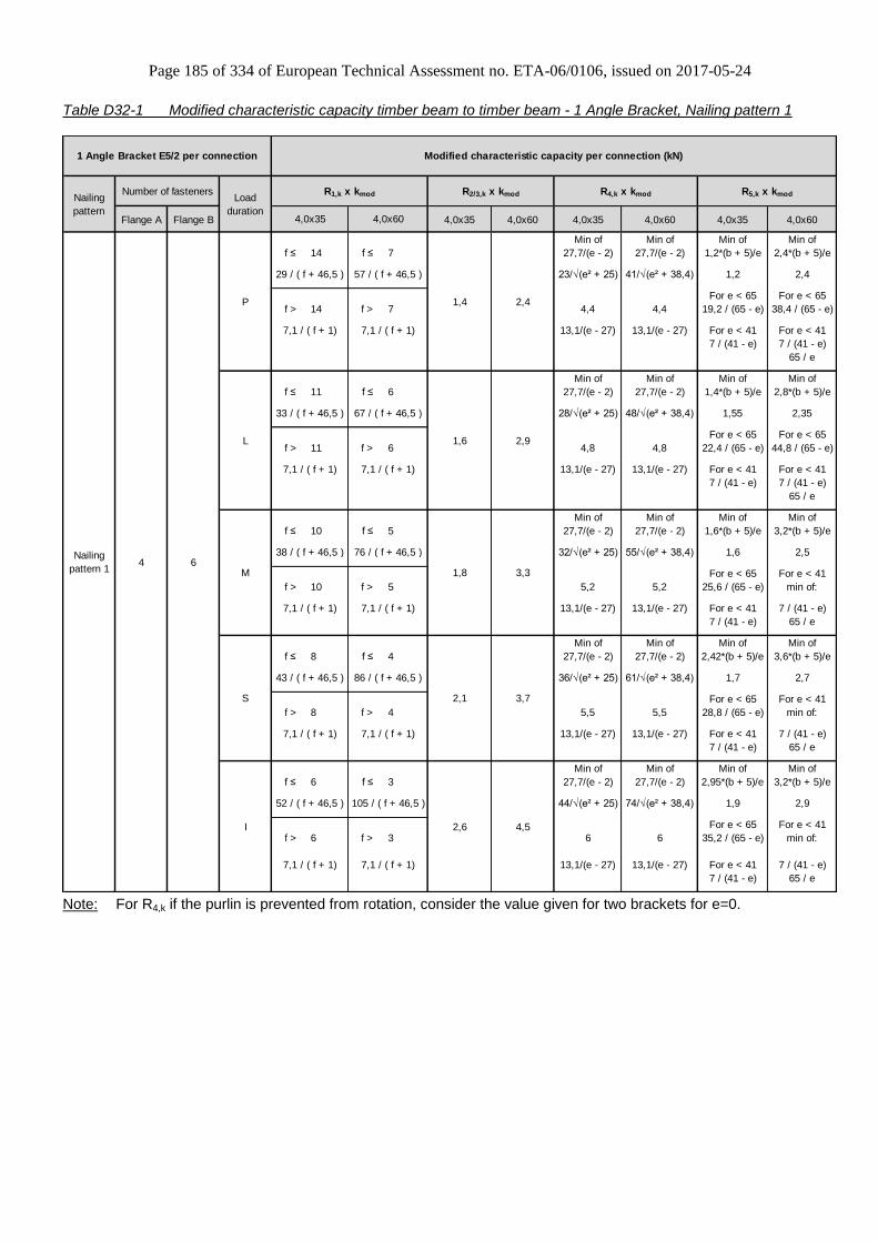
Page 185 of 334 of European Technical Assessment no. ETA-06/0106, issued on 2017-05-24
Table D32-1 Modified characteristic capacity timber beam to timber beam - 1 Angle Bracket, Nailing pattern 1
Flange A Flange B 4,0x35 4,0x60 4,0x35 4,0x60 4,0x35 4,0x60
Min of Min of Min of Min of
f ≤ 14 f ≤ 7 27,7/(e - 2) 27,7/(e - 2) 1,2*(b + 5)/e 2,4*(b + 5)/e
23/√(e² + 25) 41/√(e² + 38,4) 1,2 2,4
For e < 65 For e < 65
f > 14 f > 7 4,4 4,4 19,2 / (65 - e) 38,4 / (65 - e)
13,1/(e - 27) 13,1/(e - 27) For e < 41 For e < 41
7 / (41 - e) 7 / (41 - e)
65 / e
Min of Min of Min of Min of
f ≤ 11 f ≤ 6 27,7/(e - 2) 27,7/(e - 2) 1,4*(b + 5)/e 2,8*(b + 5)/e
28/√(e² + 25) 48/√(e² + 38,4) 1,55 2,35
For e < 65 For e < 65
f > 11 f > 6 4,8 4,8 22,4 / (65 - e) 44,8 / (65 - e)
13,1/(e - 27) 13,1/(e - 27) For e < 41 For e < 41
7 / (41 - e) 7 / (41 - e)
65 / e
Min of Min of Min of Min of
f ≤ 10 f ≤ 5 27,7/(e - 2) 27,7/(e - 2) 1,6*(b + 5)/e 3,2*(b + 5)/e
32/√(e² + 25) 55/√(e² + 38,4) 1,6 2,5
For e < 65 For e < 41
f > 10 f > 5 5,2 5,2 25,6 / (65 - e) min of:
13,1/(e - 27) 13,1/(e - 27) For e < 41 7 / (41 - e)
7 / (41 - e) 65 / e
Min of Min of Min of Min of
f ≤ 8 f ≤ 4 27,7/(e - 2) 27,7/(e - 2) 2,42*(b + 5)/e 3,6*(b + 5)/e
36/√(e² + 25) 61/√(e² + 38,4) 1,7 2,7
For e < 65 For e < 41
f > 8 f > 4 5,5 5,5 28,8 / (65 - e) min of:
13,1/(e - 27) 13,1/(e - 27) For e < 41 7 / (41 - e)
7 / (41 - e) 65 / e
Min of Min of Min of Min of
f ≤ 6 f ≤ 3 27,7/(e - 2) 27,7/(e - 2) 2,95*(b + 5)/e 3,2*(b + 5)/e
44/√(e² + 25) 74/√(e² + 38,4) 1,9 2,9
For e < 65 For e < 41
f > 6 f > 3 6 6 35,2 / (65 - e) min of:
13,1/(e - 27) 13,1/(e - 27) For e < 41 7 / (41 - e)
7 / (41 - e) 65 / e
4 6
R1,k x kmod
I
7,1 / ( f + 1)
P
L
1,4
33 / ( f + 46,5 ) 67 / ( f + 46,5 )
7,1 / ( f + 1) 7,1 / ( f + 1)
R2/3,k x kmod
29 / ( f + 46,5 )
Modified characteristic capacity per connection (kN)
R4,k x kmod
2,6
4,0x60
1,6
1,8
7,1 / ( f + 1)
Load
duration
2,1
3,3
38 / ( f + 46,5 ) 76 / ( f + 46,5 )
7,1 / ( f + 1)
M
S
R5,k x kmod
2,4
57 / ( f + 46,5 )
7,1 / ( f + 1)
4,0x35
4,5
52 / ( f + 46,5 ) 105 / ( f + 46,5 )
7,1 / ( f + 1) 7,1 / ( f + 1)
Nailing
pattern 1
Nailing
pattern
1 Angle Bracket E5/2 per connection
Number of fasteners
3,7
43 / ( f + 46,5 ) 86 / ( f + 46,5 )
7,1 / ( f + 1) 7,1 / ( f + 1)
2,9
Note: For R4,k if the purlin is prevented from rotation, consider the value given for two brackets for e=0.

Page 186 of 334 of European Technical Assessment no. ETA-06/0106, issued on 2017-05-24
Table D32-2 Modified characteristic capacity timber beam to timber beam – 2 Angle Brackets, Nailing pattern 1
Flange A Flange B 4,0x35 4,0x60 4,0x35 4,0x60
e ≤ 0,26 * b + 18 e ≤ 0,43 * b + 20
e > 0,26 * b + 18 e > 0,43 * b + 20
e ≤ 0,27 * b + 17 e ≤ 0,46 * b + 19
e > 0,27 * b + 17 e > 0,46 * b + 19
e ≤ 0,29 * b + 17 e ≤ 0,50 * b + 19
e > 0,29 * b + 17 e > 0,50 * b + 19
e ≤ 0,31 * b + 17 e ≤ 0,53 * b + 19
e > 0,31 * b + 17 e > 0,53 * b + 19
e ≤ 0,34 * b + 16 e ≤ 0,56 * b + 19
e > 0,34 * b + 16 e > 0,56 * b + 19
Modified characteristic capacity per connection (kN)2 Angle Brackets E5/2 per connection
R1,k x kmod R2/3,k x kmod R4/5,k x kmodNailing
pattern
Number of fasteners Load
duration
Nailing
pattern 14
0,74*(1,70*b+100)/(e-2) 0,87*(2,89*b+118)/(e-2)
2,5 5,0 2,8 4,9
4,8 4,8
5,4
0,74*(1,98*b+108)/(e-2) 0,87*(3,37*b+125)/(e-2)
3,0 5,8 3,2
6,7 3,7 6,5
5,76
P
L
M
5,85,4
5,7
0,74*(2,26*b+109)/(e-2) 0,87*(3,85*b+133)/(e-2)
3,7 7,5 4,2 7,4
7,1 7,1
3,3
8,8 5,2 9,1
6,7 6,7
0,74*(3,11*b+122)/(e-2)
S
I
4,0x35 4,0x60
0,87*(5,07*b+151)/(e-2)
0,74*(2,54*b+113)/(e-2) 0,87*(4,33*b+140)/(e-2)
4,6
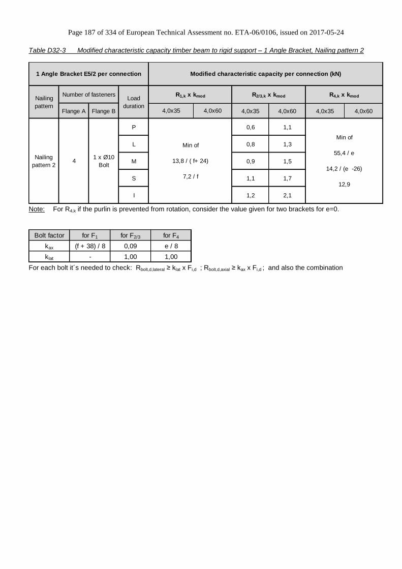
Page 187 of 334 of European Technical Assessment no. ETA-06/0106, issued on 2017-05-24
Table D32-3 Modified characteristic capacity timber beam to rigid support – 1 Angle Bracket, Nailing pattern 2
Flange A Flange B 4,0x35 4,0x60 4,0x35 4,0x60
P 0,6 1,1
L 0,8 1,3
M 0,9 1,5
S 1,1 1,7
I 1,2 2,1
Min of
13,8 / ( f+ 24)
7,2 / f
Min of
55,4 / e
14,2 / (e -26)
12,9
Load
duration
1 x Ø10
Bolt4
R1,k x kmod
4,0x35 4,0x60
Modified characteristic capacity per connection (kN)
Nailing
pattern 2
Nailing
pattern
Number of fasteners
1 Angle Bracket E5/2 per connection
R2/3,k x kmod R4,k x kmod
Note: For R4,k if the purlin is prevented from rotation, consider the value given for two brackets for e=0.
Bolt factor for F1 for F2/3 for F4
kax (f + 38) / 8 0,09 e / 8
klat - 1,00 1,00
For each bolt it´s needed to check: Rbolt,d,lateral ≥ klat x Fi,d ; Rbolt,d,axial ≥ kax x Fi,d ; and also the combination
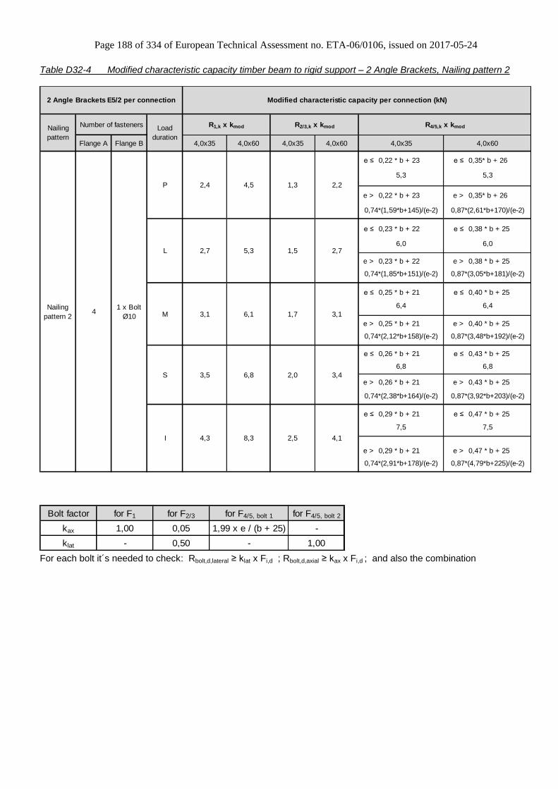
Page 188 of 334 of European Technical Assessment no. ETA-06/0106, issued on 2017-05-24
Table D32-4 Modified characteristic capacity timber beam to rigid support – 2 Angle Brackets, Nailing pattern 2
Flange A Flange B 4,0x35 4,0x60 4,0x35 4,0x60
e ≤ 0,22 * b + 23 e ≤ 0,35* b + 26
e > 0,22 * b + 23 e > 0,35* b + 26
e ≤ 0,23 * b + 22 e ≤ 0,38 * b + 25
e > 0,23 * b + 22 e > 0,38 * b + 25
e ≤ 0,25 * b + 21 e ≤ 0,40 * b + 25
e > 0,25 * b + 21 e > 0,40 * b + 25
e ≤ 0,26 * b + 21 e ≤ 0,43 * b + 25
e > 0,26 * b + 21 e > 0,43 * b + 25
e ≤ 0,29 * b + 21 e ≤ 0,47 * b + 25
e > 0,29 * b + 21 e > 0,47 * b + 25
2 Angle Brackets E5/2 per connection
Nailing
pattern 24
R1,k x kmod R2/3,k x kmod R4/5,k x kmod
5,3
4,0x35 4,0x60
2,4 4,5 1,3 2,2
Modified characteristic capacity per connection (kN)
5,3
0,74*(1,59*b+145)/(e-2) 0,87*(2,61*b+170)/(e-2)
2,7 5,3 1,5 2,76,0 6,0
0,74*(1,85*b+151)/(e-2) 0,87*(3,05*b+181)/(e-2)
3,1 6,1 1,7 3,1
6,4 6,4
0,74*(2,12*b+158)/(e-2) 0,87*(3,48*b+192)/(e-2)
3,5 6,8 2,0 3,4
6,8 6,8
0,74*(2,38*b+164)/(e-2) 0,87*(3,92*b+203)/(e-2)
7,5
0,74*(2,91*b+178)/(e-2) 0,87*(4,79*b+225)/(e-2)
4,3 8,3 2,5 4,1
7,5
Nailing
pattern
Number of fasteners Load
duration
1 x Bolt
Ø10
P
L
M
S
I
Bolt factor for F1 for F2/3 for F4/5, bolt 1 for F4/5, bolt 2
kax 1,00 0,05 1,99 x e / (b + 25) -
klat - 0,50 - 1,00
For each bolt it´s needed to check: Rbolt,d,lateral ≥ klat x Fi,d ; Rbolt,d,axial ≥ kax x Fi,d ; and also the combination
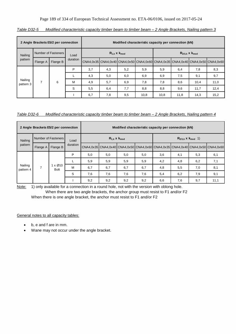
Page 189 of 334 of European Technical Assessment no. ETA-06/0106, issued on 2017-05-24
Table D32-5 Modified characteristic capacity timber beam to timber beam – 2 Angle Brackets, Nailing pattern 3
P 3,7 4,3 5,2 5,9 5,9 6,4 7,8 8,3
L 4,3 5,0 6,0 6,9 6,9 7,5 9,1 9,7
M 4,9 5,7 6,9 7,8 7,8 8,6 10,4 11,0
S 5,5 6,4 7,7 8,8 8,8 9,6 11,7 12,4
I 6,7 7,8 9,5 10,8 10,8 11,8 14,3 15,2
2 Angle Brackets E5/2 per connection
7 6
Flange A Flange B
Modified characteristic capacity per connection (kN)
R1,k x kmod R2/3,k x kmod
CNA4,0x35 CNA4,0x40
Nailing
pattern
Number of Fasteners
Nailing
pattern 3
Load
durationCNA4,0x60CNA4,0x35 CNA4,0x40 CNA4,0x50CNA4,0x50 CNA4,0x60
Table D32-6 Modified characteristic capacity timber beam to timber beam – 2 Angle Brackets, Nailing pattern 4
P 5,0 5,0 5,0 5,0 3,6 4,1 5,3 6,1
L 5,9 5,9 5,9 5,9 4,2 4,8 6,2 7,1
M 6,7 6,7 6,7 6,7 4,8 5,5 7,0 8,1
S 7,6 7,6 7,6 7,6 5,4 6,2 7,9 9,1
I 9,2 9,2 9,2 9,2 6,6 7,6 9,7 11,1
2 Angle Brackets E5/2 per connection
CNA4,0x50 CNA4,0x60
Modified characteristic capacity per connection (kN)
R1,k x kmod R2/3,k x kmod 1)
CNA4,0x35 CNA4,0x40 CNA4,0x50 CNA4,0x60
Nailing
pattern
Number of Fasteners
Nailing
pattern 4
CNA4,0x40
Load
duration
71 x Ø10
Bolt
Flange A Flange B CNA4,0x35
Note: 1) only available for a connection in a round hole, not with the version with oblong hole.
When there are two angle brackets, the anchor group must resist to F1 and/or F2
When there is one angle bracket, the anchor must resist to F1 and/or F2
General notes to all capacity tables:
b, e and f are in mm.
Wane may not occur under the angle bracket.

Page 190 of 334 of European Technical Assessment no. ETA-06/0106, issued on 2017-05-24
Annex D33 – AT1
Product Name:
Product Name Material reference
acc. to clause II-1 Alternative product names
AT1 Steel ref. 1 -
AT1S Steel ref. 2 -
AT1S2 Steel ref. 3 -
Connector Size Range:
Model no. Dimensions [mm] Holes flange A Holes flange B
A B C Thickness Ø5 Ø10 Ø5 Ø10 10x22
AT1 77,5 49 55 1,5 7 1 4 1 1
Drawing:
Nailing pattern:
Nailing pattern 1 Nailing pattern 2 Nailing pattern 3
Flange A:
Flange B:
Beam to beam
Minimum nailing Beam to beam
Maximum nailing Beam (A) to rigid support

Page 191 of 334 of European Technical Assessment no. ETA-06/0106, issued on 2017-05-24
Table D33-1 Modified characteristic capacity timber beam to timber beam – 1 Angle Bracket, Nailing pattern 1
Flange A Flange B 4,0x35 4,0x60 4,0x35 4,0x60 4,0x35 4,0x60
Min of Min of Min of Min of
f ≤ 15 f ≤ 7 17,7/(e - 1,5) 17,7/(e - 1,5) 0,7*(b + 13)/e 1,4*(b + 13)/e
15/√(e² + 24) 27/√(e² + 37,2) 1 1,5
For e < 42,5 For e < 42,5
f > 15 f > 7 3,5 3,5 21,7 / (70 - e) 43,6 / (70 - e)
5,5/(e - 36) 5,5/(e - 36) 40 / e 40 / e
5,5 / (43 - e) 5,5 / (43 - e)
Min of Min of Min of Min of
f ≤ 12 f ≤ 6 17,7/(e - 1,5) 17,7/(e - 1,5) 0,8*(b + 13)/e 1,63*(b + 13)/e
18/√(e² + 24) 32/√(e² + 37,2) 1,1 1,7
For e < 42,5 For e < 42,5
f > 12 f > 6 3,8 3,8 25,4/ (70 - e) 51 / (70 - e)
5,5/(e - 36) 5,5/(e - 36) 40 / e 40 / e
5,5 / (43 - e) 5,5 / (43 - e)
Min of Min of Min of Min of
f ≤ 10 f ≤ 5 17,7/(e - 1,5) 17,7/(e - 1,5) 0,93*(b + 13)/e 1,9*(b + 13)/e
21/√(e² + 24) 36/√(e² + 37,2) 1,2 1,7
For e < 42,5 For e < 42,5
f > 10 f > 5 4,1 4,1 29 / (70 - e) 40 / e
5,5/(e - 36) 5,5/(e - 36) 40 / e 5,5 / (43 - e)
5,5 / (43 - e)
Min of Min of Min of Min of
f ≤ 9 f ≤ 4 17,7/(e - 1,5) 17,7/(e - 1,5) 1,05*(b + 13)/e 2,1*(b + 13)/e
23/√(e² + 24) 41/√(e² + 37,2) 1,3 1,8
For e < 42,5 For e < 42,5
f > 9 f > 4 4,3 4,3 32,6 / (70 - e) 40 / e
5,5/(e - 36) 5,5/(e - 36) 40 / e 5,5 / (43 - e)
5,5 / (43 - e)
Min of Min of Min of Min of
f ≤ 7 f ≤ 3 17,7/(e - 1,5) 17,7/(e - 1,5) 1,28*(b + 13)/e 2,4*(b + 13)/e
29/√(e² + 24) 50/√(e² + 37,2) 1,4 1,9
For e < 42,5 For e < 42,5
f > 7 f > 3 4,7 4,7 40 / (70 - e) 40 / e
5,5/(e - 36) 5,5/(e - 36) 40 / e 5,5 / (43 - e)
5,5 / (43 - e)
3,1
23 / ( f + 43,5 ) 48 / ( f + 43,5 )
4,3 / ( f + 1) 4,3 / ( f + 1)
R5,k x kmod
2,1
32/ ( f + 43,5 )
4,3 / ( f + 1)
4,0x35
3,7
29 / ( f + 43,5 ) 58 / ( f + 43,5 )
4,3 / ( f + 1) 4,3 / ( f + 1)
2,3
2,7
21/ ( f + 43,5 ) 42 / ( f + 43,5 )
4,3 / ( f + 1)
2,1
4,0x60
1,3
1,5
4,3 / ( f + 1)
Load
duration
1,8
4,3 / ( f + 1)
R2/3,k x kmod
15 / ( f + 43,5 )
Modified characteristic capacity per connection (kN)
R4,k x kmod
M
R1,k x kmod
I
4,3 / ( f + 1)
P
L
1,2
18 / ( f + 43,5 ) 37 / ( f + 43,5 )
4,3 / ( f + 1)
1 Angle Bracket AT1 per connection
Nailing
pattern
Number of fasteners
Nailing
pattern 14 4
S
Note: For R4,k if the purlin is prevented from rotation, consider the value given for two brackets for e=0.

Page 192 of 334 of European Technical Assessment no. ETA-06/0106, issued on 2017-05-24
Table D33-2 Modified characteristic capacity timber beam to timber beam – 1 Angle Bracket, Nailing pattern 2
Flange A Flange B 4,0x35 4,0x60 4,0x35 4,0x60 4,0x35 4,0x60
Min of Min of Min of Min of
f ≤ 15 f ≤ 7 17,7/(e - 1,5) 17,7/(e - 1,5) 0,7*(b + 13)/e 1,4*(b + 13)/e
15/√(e² + 24) 27/√(e² + 37,2) 1 1,5
For e < 42,5 For e < 42,5
f > 15 f > 7 3,5 3,5 21,7 / (70 - e)
5,5/(e - 36) 5,5/(e - 36) 40 / e 40 / e
5,5 / (43 - e) 5,5 / (43 - e)
Min of Min of Min of Min of
f ≤ 12 f ≤ 6 17,7/(e - 1,5) 17,7/(e - 1,5) 0,8*(b + 13)/e 1,63*(b + 13)/e
18/√(e² + 24) 32/√(e² + 37,2) 1,1 1,7
For e < 42,5 For e < 42,5
f > 12 f > 6 3,8 3,8 25,4 / (70 - e)
5,5/(e - 36) 5,5/(e - 36) 40 / e 40 / e
5,5 / (43 - e) 5,5 / (43 - e)
Min of Min of Min of Min of
f ≤ 10 f ≤ 5 17,7/(e - 1,5) 17,7/(e - 1,5) 0,93*(b + 13)/e 1,9*(b + 13)/e
21/√(e² + 24) 36/√(e² + 37,2) 1,2 1,7
For e < 42,5 For e < 42,5
f > 10 f > 5 4,1 4,1 29 / (70 - e)
5,5/(e - 36) 5,5/(e - 36) 40 / e 40 / e
5,5 / (43 - e) 5,5 / (43 - e)
Min of Min of Min of Min of
f ≤ 9 f ≤ 4 17,7/(e - 1,5) 17,7/(e - 1,5) 1,05*(b + 13)/e 2,1*(b + 13)/e
23/√(e² + 24) 41/√(e² + 37,2) 1,3 1,8
For e < 42,5 For e < 42,5
f > 9 f > 4 4,3 4,3
5,5/(e - 36) 5,5/(e - 36) 40 / e 40 / e
5,5 / (43 - e) 5,5 / (43 - e)
Min of Min of Min of Min of
f ≤ 7 f ≤ 3 17,7/(e - 1,5) 17,7/(e - 1,5) 1,28*(b + 13)/e 2,4*(b + 13)/e
29/√(e² + 24) 50/√(e² + 37,2) 1,4 1,9
For e < 42,5 For e < 42,5
f > 7 f > 3 4,7 4,7
5,5/(e - 36) 5,5/(e - 36) 40 / e 40 / e
5,5 / (43 - e) 5,5 / (43 - e)
I 2,2 3,9
29 / ( f + 43,5 ) 58 / ( f + 43,5 )
4,3 / ( f + 1) 4,3 / ( f + 1)
S 1,8 3,1
23 / ( f + 43,5 ) 48 / ( f + 43,5 )
4,3 / ( f + 1) 4,3 / ( f + 1)
L 1,4 2,5
18 / ( f + 43,5 ) 37 / ( f + 43,5 )
2,8
38 / ( f + 46,5 ) 42 / ( f + 43,5 )
4,3 / ( f + 1) 4,3 / ( f + 1)
1,6
2,2
15 / ( f + 43,5 ) 32 / ( f + 43,5 )
4,3 / ( f + 1) 4,3 / ( f + 1)
R5,k x kmod
4,0x35 4,0x60
7 4
P 1,2
4,3 / ( f + 1) 4,3 / ( f + 1)
M
1 Angle Bracket AT1 per connection
Nailing
pattern
Number of fasteners
Nailing
pattern 2
Modified characteristic capacity per connection (kN)
Load
duration
R1,k x kmod R2/3,k x kmod R4,k x kmod
Note: For R4,k if the purlin is prevented from rotation, consider the value given for two brackets for e=0.
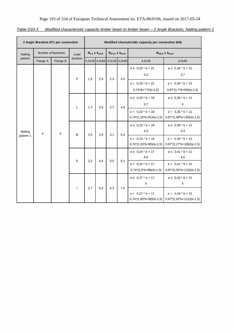
Page 193 of 334 of European Technical Assessment no. ETA-06/0106, issued on 2017-05-24
Table D33-3 Modified characteristic capacity timber beam to timber beam – 2 Angle Brackets, Nailing pattern 1
Flange A Flange B 4,0x35 4,0x60 4,0x35 4,0x60
e ≤ 0,23 * b + 21 e ≤ 0,34 * b + 21
e > 0,23 * b + 21 e > 0,34 * b + 21
e ≤ 0,23 * b + 19 e ≤ 0,36 * b + 21
e > 0,23 * b + 19 e > 0,36 * b + 21
e ≤ 0,23 * b + 18 e ≤ 0,39 * b + 21
e > 0,23 * b + 18 e > 0,39 * b + 21
e ≤ 0,24 * b + 17 e ≤ 0,41 * b + 21
e > 0,24 * b + 17 e > 0,41 * b + 21
e ≤ 0,27 * b + 17 e ≤ 0,43 * b + 21
e > 0,27 * b + 17 e > 0,43 * b + 21
Load
duration
0,74*(1,5*b+88)/(e-1,5) 0,87*(2,55*b+113)/(e-1,5)
I 2,7 7,5
5 5
0,74*(1,83*b+96)/(e-1,5)
4,0x35 4,0x60
0,87*(2,92*b+121)/(e-1,5)
4,3
0,74*(1,33*b+85)/(e-1,5) 0,87*(2,27*b+106)/(e-1,5)
4,6
S 2,2 4,4 3,5 6,1
4,6
M 2,0 3,9 3,1 5,4
4,3
P
0,74*(1,16*b+81)/(e-1,5) 0,87*(1,98*b+100)/(e-1,5)
L 1,7 3,5 2,7
4 4
0,74*(b+77)/(e-1,5) 0,87*(1,7*b+93)/(e-1,5)
1,5 2,9 2,3 4,0
3,2 3,7
Modified characteristic capacity per connection (kN)
R1,k x kmod R2/3,k x kmod R4/5,k x kmod
4,83,7 4
4,3
Nailing
pattern 1
Nailing
pattern
2 Angle Brackets AT1 per connection
Number of fasteners
5,0

Page 194 of 334 of European Technical Assessment no. ETA-06/0106, issued on 2017-05-24
Table D33-4 Modified characteristic capacity timber beam to timber beam – 2 Angle Brackets, Nailing pattern 2
Flange A Flange B 4,0x35 4,0x40 4,0x50 4,0x60 4,0x35 4,0x40 4,0x50 4,0x60
e ≤ 0,23 * b + 21 e ≤ 0,34 * b + 21
e > 0,23 * b + 21 e > 0,34 * b + 21
e ≤ 0,23 * b + 19 e ≤ 0,36 * b + 21
e > 0,23 * b + 19 e > 0,36 * b + 21
e ≤ 0,23 * b + 18 e ≤ 0,39 * b + 21
e > 0,23 * b + 18 e > 0,39 * b + 21
e ≤ 0,24 * b + 17 e ≤ 0,41 * b + 21
e > 0,24 * b + 17 e > 0,41 * b + 21
e ≤ 0,27 * b + 17 e ≤ 0,43 * b + 21
e > 0,27 * b + 17 e > 0,43 * b + 21
Modified characteristic capacity per connection (kN)
Load
duration
R1,k x kmod R2/3,k x kmod R4/5,k x kmod
4,0x35 4,0x60
4 6
P 3,4 4,1 4,8 4,8 5,6 6,1 7,4 7,9
3,2 3,7
0,74*(b+77)/(e-1,5) 0,87*(1,7*b+93)/(e-1,5)
L 3,4 4,1 4,8 4,8 5,6 6,1 7,4 7,93,7 4,0
0,74*(1,16*b+81)/(e-1,5) 0,87*(1,98*b+100)/(e-1,5)
M 3,4 4,1 4,8 4,8 5,6 6,1 7,4 7,9
4,3 4,3
0,74*(1,33*b+85)/(e-1,5) 0,87*(2,27*b+106)/(e-1,5)
7,9
4,6 4,6
0,74*(1,5*b+88)/(e-1,5) 0,87*(2,55*b+113)/(e-1,5)
S 3,4 4,1 4,8 4,8
7,9
5,0 5,0
0,74*(1,83*b+96)/(e-1,5) 0,87*(2,92*b+121)/(e-1,5)
I 3,4 4,1 4,8 4,8
2 Angle Brackets AT1 per connection
Nailing
pattern
Number of fasteners
Nailing
pattern 2
6,1 7,45,6
6,1 7,45,6
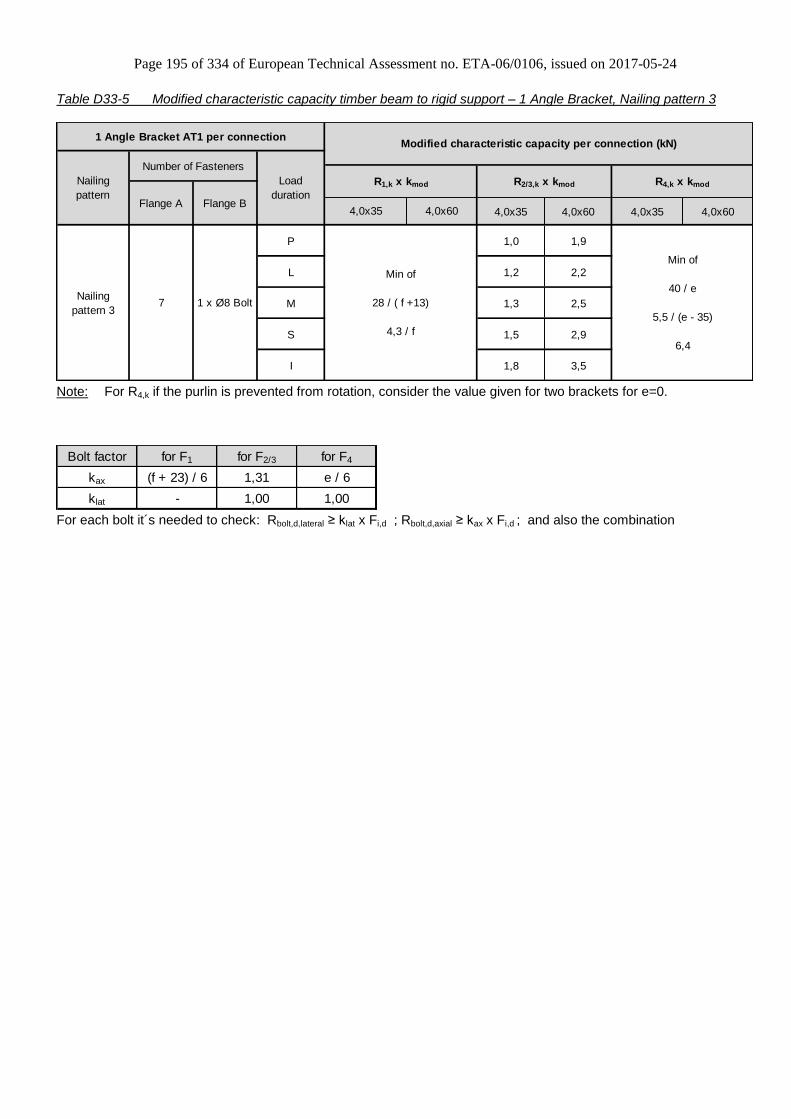
Page 195 of 334 of European Technical Assessment no. ETA-06/0106, issued on 2017-05-24
Table D33-5 Modified characteristic capacity timber beam to rigid support – 1 Angle Bracket, Nailing pattern 3
4,0x35 4,0x60 4,0x35 4,0x60
P 1,0 1,9
L 1,2 2,2
M 1,3 2,5
S 1,5 2,9
I 1,8 3,5
Modified characteristic capacity per connection (kN)
R2/3,k x kmod R4,k x kmod
Min of
28 / ( f +13)
4,3 / f
Min of
40 / e
5,5 / (e - 35)
6,4
Number of Fasteners
Load
durationFlange A Flange B
Nailing
pattern 31 x Ø8 Bolt7
R1,k x kmod
4,0x35 4,0x60
1 Angle Bracket AT1 per connection
Nailing
pattern
Note: For R4,k if the purlin is prevented from rotation, consider the value given for two brackets for e=0.
Bolt factor for F1 for F2/3 for F4
kax (f + 23) / 6 1,31 e / 6
klat - 1,00 1,00
For each bolt it´s needed to check: Rbolt,d,lateral ≥ klat x Fi,d ; Rbolt,d,axial ≥ kax x Fi,d ; and also the combination
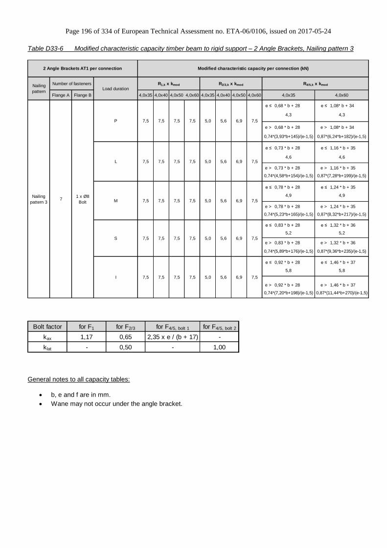
Page 196 of 334 of European Technical Assessment no. ETA-06/0106, issued on 2017-05-24
Table D33-6 Modified characteristic capacity timber beam to rigid support – 2 Angle Brackets, Nailing pattern 3
Flange A Flange B 4,0x35 4,0x40 4,0x50 4,0x60 4,0x35 4,0x40 4,0x50 4,0x60
e ≤ 0,68 * b + 28 e ≤ 1,08* b + 34
e > 0,68 * b + 28 e > 1,08* b + 34
e ≤ 0,73 * b + 28 e ≤ 1,16 * b + 35
e > 0,73 * b + 28 e > 1,16 * b + 35
e ≤ 0,78 * b + 28 e ≤ 1,24 * b + 35
e > 0,78 * b + 28 e > 1,24 * b + 35
e ≤ 0,83 * b + 28 e ≤ 1,32 * b + 36
e > 0,83 * b + 28 e > 1,32 * b + 36
e ≤ 0,92 * b + 28 e ≤ 1,46 * b + 37
e > 0,92 * b + 28 e > 1,46 * b + 37
0,87*(9,36*b+235)/(e-1,5)
5,8
0,74*(7,20*b+198)/(e-1,5) 0,87*(11,44*b+270)/(e-1,5)
I 7,5 7,5 5,0 7,5
5,8
0,74*(5,23*b+165)/(e-1,5) 0,87*(8,32*b+217)/(e-1,5)
S 7,5 7,5 5,0 7,5
5,2 5,2
0,74*(5,89*b+176)/(e-1,5)
4,6
0,74*(4,58*b+154)/(e-1,5) 0,87*(7,28*b+199)/(e-1,5)
M 7,5 7,5 5,0 7,5
4,9 4,9
7,5
4,3
0,74*(3,93*b+145)/(e-1,5) 0,87*(6,24*b+182)/(e-1,5)
L 7,5 7,5 5,0 7,54,6
4,3
Load duration
4,0x35 4,0x60
P 7,5 7,5 5,0
7,5
7,5
7,5
7,5
Modified characteristic capacity per connection (kN)
71 x Ø8
Bolt
R1,k x kmod R2/3,k x kmod R4/5,k x kmod
6,9
6,9
6,9
6,9
6,9
7,5
7,5
7,5
7,5
7,5
2 Angle Brackets AT1 per connection
Nailing
pattern
Number of fasteners
Nailing
pattern 3
5,6
5,6
5,6
5,6
5,6
7,5
Bolt factor for F1 for F2/3 for F4/5, bolt 1 for F4/5, bolt 2
kax 1,17 0,65 2,35 x e / (b + 17) -
klat - 0,50 - 1,00
General notes to all capacity tables:
b, e and f are in mm.
Wane may not occur under the angle bracket.

Page 197 of 334 of European Technical Assessment no. ETA-06/0106, issued on 2017-05-24
Annex D34 – E4/2.5
Product Name:
Product Name Material reference
acc. to clause II-1 Alternative product names
E4/2.5 Steel ref. 1 -
E4/2.5S Steel ref. 2 -
E4/2.5S2 Steel ref. 3 -
Connector Size Range:
Model no. Dimensions [mm] Holes flange A Holes flange B
A B C Thickness Ø5 Ø13 Ø5 12x20
E4/2.5 102,5 62,5 75 2,5 8 1 6 1 *)
*) Optional round Hole Ø12
Drawing:
Nailing pattern:
Nailing pattern 1 Nailing pattern 2 Nailing pattern 3
Flange A:
Flange B:
Beam to beam
Minimum nailing Beam to beam
Maximum nailing Beam (A) to rigid support
Optional: Round Hole Ø12
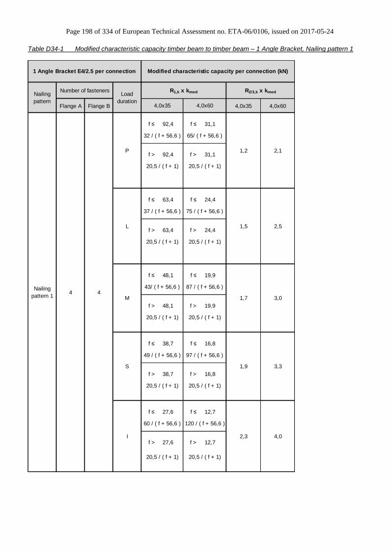
Page 198 of 334 of European Technical Assessment no. ETA-06/0106, issued on 2017-05-24
Table D34-1 Modified characteristic capacity timber beam to timber beam – 1 Angle Bracket, Nailing pattern 1
Flange A Flange B 4,0x35 4,0x60
f ≤ 92,4 f ≤ 31,1
f > 92,4 f > 31,1
f ≤ 63,4 f ≤ 24,4
f > 63,4 f > 24,4
f ≤ 48,1 f ≤ 19,9
f > 48,1 f > 19,9
f ≤ 38,7 f ≤ 16,8
f > 38,7 f > 16,8
f ≤ 27,6 f ≤ 12,7
f > 27,6 f > 12,7
P
L
1,2
37 / ( f + 56,6 ) 75 / ( f + 56,6 )
20,5 / ( f + 1) 20,5 / ( f + 1)
R2/3,k x kmod
32 / ( f + 56,6 )
Modified characteristic capacity per connection (kN)
R1,k x kmod
2,3
4,0x60
1,5
1,7
20,5 / ( f + 1)
Load
duration
1,9
4,0x35
I
20,5 / ( f + 1)
3,0
43/ ( f + 56,6 ) 87 / ( f + 56,6 )
3,3
M
S
2,1
65/ ( f + 56,6 )
20,5 / ( f + 1)
20,5 / ( f + 1)
4,0
60 / ( f + 56,6 ) 120 / ( f + 56,6 )
20,5 / ( f + 1) 20,5 / ( f + 1)
2,5
Nailing
pattern 1
Nailing
pattern
1 Angle Bracket E4/2.5 per connection
Number of fasteners
49 / ( f + 56,6 ) 97 / ( f + 56,6 )
20,5 / ( f + 1) 20,5 / ( f + 1)
4 4

Page 199 of 334 of European Technical Assessment no. ETA-06/0106, issued on 2017-05-24
Table D34-2 Modified characteristic capacity timber beam to timber beam – 1 Angle Bracket, Nailing pattern 2
Flange A Flange B 4,0x35 4,0x60
f ≤ 65,9 f ≤ 25
f > 65,9 f > 25
f ≤ 47,8 f ≤ 19,8
f > 47,8 f > 19,8
f ≤ 37,4 f ≤ 16,3
f > 37,4 f > 16,3
f ≤ 30,6 f ≤ 13,9
f > 30,6 f > 13,9
f ≤ 22,3 f ≤ 10,5
f > 22,3 f > 10,5
L
Modified characteristic capacity per connection (kN)
Load
duration
R1,k x kmod R2/3,k x kmod
4,0x35 4,0x60
20,5 / ( f + 1)
8 6
P 1,3 2,6
37 / ( f + 56,6 ) 75/ ( f + 56,6 )
20,5 / ( f + 1) 20,5 / ( f + 1)
3,5
50/ ( f + 56,6 ) 99 / ( f + 56,6 )
20,5 / ( f + 1) 20,5 / ( f + 1)
1,5 3,0
43 / ( f + 56,6 ) 87 / ( f + 56,6 )
20,5 / ( f + 1)
4,8
68 / ( f + 56,6 ) 136 / ( f + 56,6 )
20,5 / ( f + 1) 20,5 / ( f + 1)
S 2,1 4,0
56 / ( f + 56,6 ) 112 / ( f + 56,6 )
1 Angle Bracket E4/2.5 per connection
Nailing
pattern
Number of fasteners
Nailing
pattern 2
I 2,5
20,5 / ( f + 1) 20,5 / ( f + 1)
M 1,7

Page 200 of 334 of European Technical Assessment no. ETA-06/0106, issued on 2017-05-24
Table D34-3 Modified characteristic capacity timber beam to timber beam – 2 Angle Brackets, Nailing pattern 2
P 3,3 3,8 4,3 4,6 4,6 5,0 6,1 6,4
L 3,9 4,4 5,0 5,3 5,3 5,8 7,1 7,5
M 4,4 5,0 5,8 6,1 6,1 6,6 8,1 8,6
S 5,0 5,7 6,5 6,8 6,8 7,5 9,1 9,6
I 6,1 6,9 7,9 8,4 8,4 9,1 11,1 11,8
Flange A Flange B CNA4,0x35 CNA4,0x35 CNA4,0x40 CNA4,0x50
Modified characteristic capacity per connection (kN)
Load
duration
R1,k x kmod R2/3,k x kmod
Nailing
pattern 2
Nailing
pattern
2 Angle Brackets E4/2.5 per connection
Number of Fasteners
CNA4,0x60
8 6
CNA4,0x40 CNA4,0x50 CNA4,0x60
Table D34-4 Modified characteristic capacity timber beam to rigid support – 1 Angle Bracket, Nailing pattern 3
Flange A Flange B 4,0x35 4,0x60
P 0,6 1,2
L 0,7 1,4
M 0,8 1,7
S 0,9 1,9
I 1,1 2,2
4,0x35 4,0x60
Modified characteristic capacity per connection (kN)
R2/3,k x kmod 1)
Nailing
pattern 3
Nailing
pattern
1 Angle Bracket E4/2.5 per connection
Number of fasteners
Min of
15,4 / (f+13)
20,5 / f
Load
duration
1 x Ø10
Bolt7
R1,k x kmod
Note: 1) only available for connection in a round hole, not with the version with oblong hole.
Bolt factor for F1 for F2/3
kax (f + 41,5) / 8 1,87
klat - 1,00
For each bolt it´s needed to check: Rbolt,d,lateral ≥ klat x Fi,d ; Rbolt,d,axial ≥ kax x Fi,d ; and also the combination
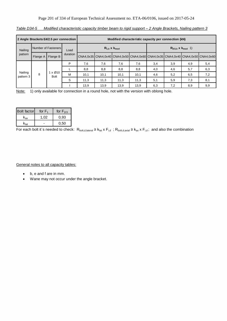
Page 201 of 334 of European Technical Assessment no. ETA-06/0106, issued on 2017-05-24
Table D34-5 Modified characteristic capacity timber beam to rigid support – 2 Angle Brackets, Nailing pattern 3
P 7,6 7,6 7,6 7,6 3,4 3,9 4,9 5,4
L 8,8 8,8 8,8 8,8 4,0 4,6 5,7 6,3
M 10,1 10,1 10,1 10,1 4,6 5,2 6,5 7,2
S 11,3 11,3 11,3 11,3 5,1 5,9 7,3 8,1
I 13,9 13,9 13,9 13,9 6,3 7,2 8,9 9,9
Flange A Flange B CNA4,0x35 CNA4,0x35 CNA4,0x40 CNA4,0x50
Modified characteristic capacity per connection (kN)
Load
duration
R1,k x kmod R2/3,k x kmod 1)Nailing
pattern
Nailing
pattern 3
2 Angle Brackets E4/2.5 per connection
Number of Fasteners
CNA4,0x60
81 x Ø10
Bolt
CNA4,0x40 CNA4,0x50 CNA4,0x60
Note: 1) only available for connection in a round hole, not with the version with oblong hole.
Bolt factor for F1 for F2/3
kax 1,02 0,93
klat - 0,50
For each bolt it´s needed to check: Rbolt,d,lateral ≥ klat x Fi,d ; Rbolt,d,axial ≥ kax x Fi,d ; and also the combination
General notes to all capacity tables:
b, e and f are in mm.
Wane may not occur under the angle bracket.

Page 202 of 334 of European Technical Assessment no. ETA-06/0106, issued on 2017-05-24
Annex D35 – E6/2
Product Name:
Product Name Material reference
acc. to clause II-1 Alternative product names
E6/2 Steel ref. 1 -
E6/2S Steel ref. 2 -
E6/2S2 Steel ref. 3 -
Connector Size Range:
Model no. Dimensions [mm] Holes flange A Holes flange B
A B C Thickness Ø5 Ø13 Ø5 12x20
E6/2 122 62 75 2,0 11 1 6 1 *)
*) Optional round Hole Ø12
Drawing:
Nailing pattern:
Nailing pattern 1 Nailing pattern 2 Nailing pattern 3 Nailing pattern 4 Nailing pattern 5
Flange A:
Flange B:
Beam to beam
Minimum nailing Beam to beam
Maximum nailing Column (A) to
beam (B) Beam (A) to
rigid support (B) Column (A) to
rigid support (B)
Optional: Round Hole Ø12
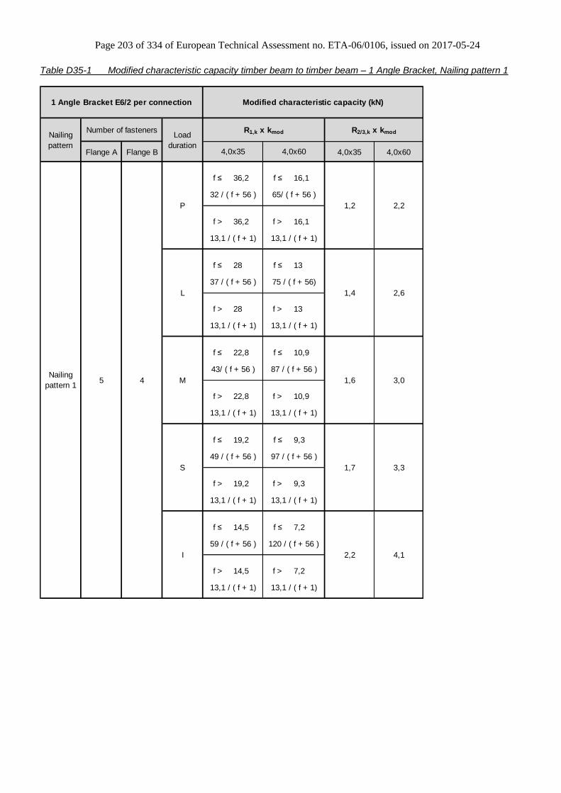
Page 203 of 334 of European Technical Assessment no. ETA-06/0106, issued on 2017-05-24
Table D35-1 Modified characteristic capacity timber beam to timber beam – 1 Angle Bracket, Nailing pattern 1
Flange A Flange B 4,0x35 4,0x60
f ≤ 36,2 f ≤ 16,1
f > 36,2 f > 16,1
f ≤ 28 f ≤ 13
f > 28 f > 13
f ≤ 22,8 f ≤ 10,9
f > 22,8 f > 10,9
f ≤ 19,2 f ≤ 9,3
f > 19,2 f > 9,3
f ≤ 14,5 f ≤ 7,2
f > 14,5 f > 7,2
13,1 / ( f + 1)
13,1 / ( f + 1)
4,1
59 / ( f + 56 ) 120 / ( f + 56 )
13,1 / ( f + 1) 13,1 / ( f + 1)
2,6
3,0
43/ ( f + 56 ) 87 / ( f + 56 )
3,3
2,2
4,0x60
1,4
1,6
13,1 / ( f + 1)
Load
duration
1,7
4,0x35
49 / ( f + 56 ) 97 / ( f + 56 )
13,1 / ( f + 1)
R2/3,k x kmod
32 / ( f + 56 )
Modified characteristic capacity (kN)
M
S
13,1 / ( f + 1) 13,1 / ( f + 1)
2,2
65/ ( f + 56 )
R1,k x kmod
I
13,1 / ( f + 1)
P
L
1,2
37 / ( f + 56 ) 75 / ( f + 56)
13,1 / ( f + 1)
Nailing
pattern 1
Nailing
pattern
1 Angle Bracket E6/2 per connection
Number of fasteners
5 4

Page 204 of 334 of European Technical Assessment no. ETA-06/0106, issued on 2017-05-24
Table D35-2 Modified characteristic capacity timber beam to timber beam – 1 Angle Bracket, Nailing pattern 2
Flange A Flange B 4,0x35 4,0x60
f ≤ 28,7 f ≤ 13,3
f > 28,7 f > 13,3
f ≤ 22,7 f ≤ 10,8
f > 22,7 f > 10,8
f ≤ 18,7 f ≤ 9,1
f > 18,7 f > 9,1
f ≤ 15,8 f ≤ 7,8
f > 15,8 f > 7,8
f ≤ 12 f ≤ 6
f > 12 f > 6
L
Modified characteristic capacity (kN)
Load
duration
R1,k x kmod R2/3,k x kmod
4,0x35 4,0x60
13,1 / ( f + 1)
11 6
P 1,5 2,9
37 / ( f + 56 ) 75/ ( f + 56 )
13,1 / ( f + 1) 13,1 / ( f + 1)
3,9
50/ ( f + 56 ) 99 / ( f + 56 )
13,1 / ( f + 1) 13,1 / ( f + 1)
1,8 3,4
44 / ( f + 56 ) 87 / ( f + 56)
13,1 / ( f + 1)
5,3
68 / ( f + 56 ) 136 / ( f + 56 )
13,1 / ( f + 1) 13,1 / ( f + 1)
S 2,4 4,3
56 / ( f + 56 ) 112 / ( f + 56 )
Nailing
pattern 2
Nailing
pattern
1 Angle Bracket E6/2 per connection
Number of fasteners
I 2,9
13,1 / ( f + 1) 13,1 / ( f + 1)
M 2,1

Page 205 of 334 of European Technical Assessment no. ETA-06/0106, issued on 2017-05-24
Table D35-3 Modified characteristic capacity timber beam to timber beam – 2 Angle Brackets, Nailing pattern 1
P 1,5 2,9 2,4 4,4
L 1,7 3,5 2,8 5,1
M 2,0 3,9 3,2 5,8
S 2,2 4,4 3,6 6,6
I 2,7 5,4 4,4 8,0
Nailing
pattern 2
Nailing
pattern
5 4
CNA4,0x60 CNA4,0x35
Load
duration
R1,k x kmod R2/3,k x kmod
2 Angle Brackets E6/2 per connection
Number of Fasteners
Flange A Flange B CNA4,0x35 CNA4,0x60
Modified characteristic capacities (kN)
Table D35-4 Modified characteristic capacity timber beam to timber beam – 2 Angle Brackets, Nailing pattern 2
P 2,5 5,0 3,2 5,7
L 3,0 5,8 3,7 6,7
M 3,3 6,7 4,2 7,7
S 3,8 7,5 4,7 8,7
I 4,6 9,2 5,8 10,6
2 Angle Brackets E6/2 per connection
Number of Fasteners
CNA4,0x60 CNA4,0x35 CNA4,0x60
11 6
Nailing
pattern
Nailing
pattern 2
Modified characteristic capacities (kN)
Load
duration
R1,k x kmod R2/3,k x kmod
Flange A Flange B CNA4,0x35

Page 206 of 334 of European Technical Assessment no. ETA-06/0106, issued on 2017-05-24
Table D35-5 Modified characteristic capacity timber column to timber beam – 1 Angle Bracket Nailing pattern 2 & 3
Flange A Flange B 4,0x35 4,0x60
f ≤ 28,7 f ≤ 13,3
f > 28,7 f > 13,3
f ≤ 22,7 f ≤ 10,8
f > 22,7 f > 10,8
f ≤ 18,7 f ≤ 9,1
f > 18,7 f > 9,1
f ≤ 15,8 f ≤ 7,8
f > 15,8 f > 7,8
f ≤ 12 f ≤ 6
f > 12 f > 6
R1,k x kmod
Nailing pattern 3
R2/3,k x kmod
Nailing pattern 2Number of fasteners
1 Angle Bracket E6/2 per connection Modified characteristic capacity (kN)
Load
duration
4,0x35 4,0x60
For R1: 8
For R2/3: 11
6
P 1,5 2,9
37 / ( f + 56 ) 75/ ( f + 56 )
13,1 / ( f + 1) 13,1 / ( f + 1)
L 1,8 3,4
43 / ( f + 56 ) 87 / ( f + 56)
13,1 / ( f + 1) 13,1 / ( f + 1)
M 2,1 3,9
49/ ( f + 56 ) 99 / ( f + 56 )
13,1 / ( f + 1) 13,1 / ( f + 1)
S 2,4 4,3
56 / ( f + 56 ) 112 / ( f + 56 )
13,1 / ( f + 1) 13,1 / ( f + 1)
I 2,9 5,3
68 / ( f + 56 ) 136 / ( f + 56 )
13,1 / ( f + 1) 13,1 / ( f + 1)
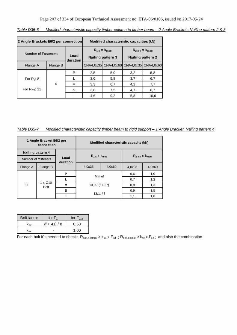
Page 207 of 334 of European Technical Assessment no. ETA-06/0106, issued on 2017-05-24
Table D35-6 Modified characteristic capacity timber column to timber beam – 2 Angle Brackets Nailing pattern 2 & 3
P 2,5 5,0 3,2 5,8
L 3,0 5,8 3,7 6,7
M 3,3 6,7 4,2 7,7
S 3,8 7,5 4,7 8,7
I 4,6 9,2 5,8 10,6
R1,k x kmod
Nailing pattern 3
R2/3,k x kmod
CNA4,0x60 CNA4,0x35 CNA4,0x60
For R1: 8
For R2/3: 11
6
2 Angle Brackets E6/2 per connection Modified characteristic capacities (kN)
Load
durationNailing pattern 2
Flange A Flange B CNA4,0x35
Number of Fasteners
Table D35-7 Modified characteristic capacity timber beam to rigid support – 1 Angle Bracket, Nailing pattern 4
Flange A Flange B 4,0x35 4,0x60
P 0,6 1,0
L 0,7 1,2
M 0,8 1,3
S 0,9 1,5
I 1,1 1,8
Nailing pattern 4
Number of fastenersR2/3,k x kmod
Min of
10,9 / (f + 27)
13,1, / f
Load
duration
1 x Ø10
Bolt11
1 Angle Bracket E6/2 per
connection
R1,k x kmod
4,0x35 4,0x60
Modified characteristic capacity (kN)
Bolt factor for F1 for F2/3
kax (f + 41) / 8 0,53
klat - 1,00
For each bolt it´s needed to check: Rbolt,d,lateral ≥ klat x Fi,d ; Rbolt,d,axial ≥ kax x Fi,d ; and also the combination

Page 208 of 334 of European Technical Assessment no. ETA-06/0106, issued on 2017-05-24
Table D35-8 Modified characteristic capacity timber beam to rigid support – 2 Angle Brackets, Nailing pattern 4
P 3,9 7,7 1,2 2,0
L 4,6 9,0 1,4 2,3
M 5,2 9,7 1,6 2,6
S 5,8 9,7 1,8 3,0
I 7,2 9,7 2,2 3,7
CNA4,0x60 CNA4,0x35 CNA4,0x60
111 x Ø10
Bolt
2 Angle Brackets E6/2 per
connectionModified characteristic capacities (kN)
Nailing pattern 4
Load
duration
R1,k x kmod R2/3,k x kmodNumber of Fasteners
Flange A Flange B CNA4,0x35
Bolt factor for F1 for F2/3
kax 1,02 0,27
klat - 0,50
For each bolt it´s needed to check: Rbolt,d,lateral ≥ klat x Fi,d ; Rbolt,d,axial ≥ kax x Fi,d ; and also the combination
Table D35-9 Modified characteristic capacity timber column to rigid support – 1 Angle Bracket Nailing pattern 4 & 5
Flange A Flange B 4,0x35 4,0x60
P 0,6 1,0
L 0,7 1,2
M 0,8 1,3
S 0,9 1,5
I 1,1 1,8
Nailing pattern 4
For R1: 8
For R2/3: 11
1 x Ø10
Bolt
Min of
10,9 / (f+27)
13,1, / f
1 Angle Bracket E6/2 per connection Modified characteristic capacity (kN)
Load
duration
4,0x35 4,0x60
Number of fastenersR1,k x kmod R2/3,k x kmod
Nailing pattern5
Bolt factor for F1 for F2/3
kax (f + 41) / 8 0,53
klat - 1,00
For each bolt it´s needed to check: Rbolt,d,lateral ≥ klat x Fi,d ; Rbolt,d,axial ≥ kax x Fi,d ; and also the combination

Page 209 of 334 of European Technical Assessment no. ETA-06/0106, issued on 2017-05-24
Table D35-10 Modified characteristic capacity timber column to rigid support – 2 Angle Brackets Nailing pattern 4 & 5
P 2,0 4,0 1,2 2,0
L 2,2 4,6 1,4 2,3
M 2,6 5,3 1,6 2,6
S 3,0 5,9 1,8 3,0
I 3,7 7,3 2,2 3,7
R2/3,k x kmod
Nailing pattern 5 Nailing pattern 4
CNA4,0x60 CNA4,0x35 CNA4,0x60
For R1: 8
For R2/3: 11
1 x Ø10
Bolt
2 Angle Brackets E6/2 per
connectionModified characteristic capacities (kN)
Load
duration
Flange A Flange B CNA4,0x35
Number of FastenersR1,k x kmod
Bolt factor for F1 for F2/3
kax 1,02 0,27
klat - 0,50
For each bolt it´s needed to check: Rbolt,d,lateral ≥ klat x Fi,d ; Rbolt,d,axial ≥ kax x Fi,d ; and also the combination
General note to all capacity tables:
b, e and f are in mm.
Wane may not occur under the angle bracket.

Page 210 of 334 of European Technical Assessment no. ETA-06/0106, issued on 2017-05-24
Annex D36 – E6/2,5
Product Name:
Product Name Material reference
acc. to clause II-1 Alternative product names
E6/2,5 Steel ref. 1 -
E6/2,5S Steel ref. 2 -
E6/2,5S2 Steel ref. 3 -
Connector Size Range:
Model no.
Dimensions [mm] Holes flange
A
Holes flange
B
A B C Thicknes
s Ø5 Ø13 Ø5 12x20
E6/2,5 122,5 62,5 75 2,5 11 1 6 1 *)
*) Optional round Hole Ø12
Drawing:
Nailing pattern:
Nailing pattern 1 Nailing pattern 2 Nailing pattern 3 Nailing pattern 4 Nailing pattern 5
Flange A:
Flange B:
Beam to beam
Minimum nailing Beam to beam
Maximum nailing Column (A) to
beam (B) Beam (A) to
rigid support (B) Column (A) to
rigid support (B)
Optional: Round Hole Ø12

Page 211 of 334 of European Technical Assessment no. ETA-06/0106, issued on 2017-05-24
Table D36-1 Modified characteristic capacity timber beam to timber beam – 1 Angle Bracket, Nailing pattern 1
Flange A Flange B 4,0x35 4,0x60
f ≤ 92,8 f ≤ 31,2
f > 92,8 f > 31,2
f ≤ 63,6 f ≤ 24,4
f > 63,6 f > 24,4
f ≤ 48,2 f ≤ 20
f > 48,2 f > 20
f ≤ 38,8 f ≤ 16,8
f > 38,8 f > 16,8
f ≤ 27,7 f ≤ 12,7
f > 27,7 f > 12,7
49 / ( f + 56 ) 97 / ( f + 56 )
20,5 / ( f + 1) 20,5 / ( f + 1)
2,1
65/ ( f + 56 )
20,5 / ( f + 1)
20,5 / ( f + 1)
4,0
59 / ( f + 56 ) 120 / ( f + 56 )
20,5 / ( f + 1) 20,5 / ( f + 1)
2,5
3,0
43/ ( f + 56 ) 87 / ( f + 56 )
3,3
M
S
2,2
4,0x60
1,5
1,7
20,5 / ( f + 1)
Load
duration
1,8
4,0x35
1,2
37 / ( f + 56 ) 75 / ( f + 56)
20,5 / ( f + 1) 20,5 / ( f + 1)
R2/3,k x kmod
32 / ( f + 56 )
Modified characteristic capacity (kN)1 Angle Bracket E6/2.5 per
connection
Nailing pattern 1
Number of fasteners
5 4
R1,k x kmod
I
20,5 / ( f + 1)
P
L

Page 212 of 334 of European Technical Assessment no. ETA-06/0106, issued on 2017-05-24
Table D36-2 Modified characteristic capacity timber beam to timber beam – 1 Angle Bracket, Nailing pattern 2
Flange A Flange B 4,0x35 4,0x60
f ≤ 65,9 f ≤ 25
f > 65,9 f > 25
f ≤ 47,8 f ≤ 19,8
f > 47,8 f > 19,8
f ≤ 37,4 f ≤ 16,3
f > 37,4 f > 16,3
f ≤ 30,6 f ≤ 13,9
f > 30,6 f > 13,9
f ≤ 22,3 f ≤ 10,5
f > 22,3 f > 10,5
1 Angle Bracket E6/2.5 per
connectionModified characteristic capacity (kN)
Nailing pattern 2
Load
duration
R1,k x kmod R2/3,k x kmod
Number of fasteners
4,0x35 4,0x60
11 6
P 1,5 2,9
37 / ( f + 56 ) 75/ ( f + 56 )
20,5 / ( f + 1) 20,5 / ( f + 1)
L 1,8 3,3
43 / ( f + 56 ) 87 / ( f + 56)
20,5 / ( f + 1) 20,5 / ( f + 1)
M 2,1 3,9
50/ ( f + 56 ) 99 / ( f + 56 )
20,5 / ( f + 1) 20,5 / ( f + 1)
S 2,4 4,3
56 / ( f + 56 ) 112 / ( f + 56 )
20,5 / ( f + 1) 20,5 / ( f + 1)
I 2,9 5,3
68 / ( f + 56 ) 136 / ( f + 56 )
20,5 / ( f + 1) 20,5 / ( f + 1)
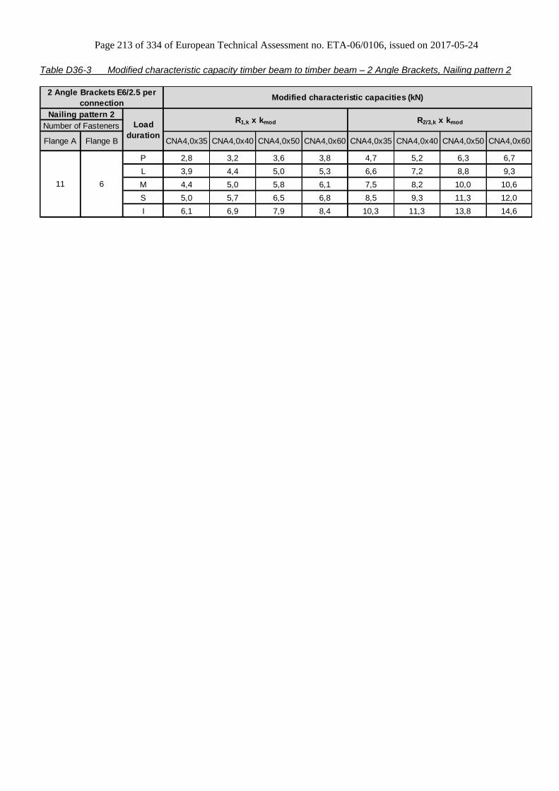
Page 213 of 334 of European Technical Assessment no. ETA-06/0106, issued on 2017-05-24
Table D36-3 Modified characteristic capacity timber beam to timber beam – 2 Angle Brackets, Nailing pattern 2
P 2,8 3,2 3,6 3,8 4,7 5,2 6,3 6,7
L 3,9 4,4 5,0 5,3 6,6 7,2 8,8 9,3
M 4,4 5,0 5,8 6,1 7,5 8,2 10,0 10,6
S 5,0 5,7 6,5 6,8 8,5 9,3 11,3 12,0
I 6,1 6,9 7,9 8,4 10,3 11,3 13,8 14,6
Flange B CNA4,0x35 CNA4,0x60 CNA4,0x35 CNA4,0x60CNA4,0x40 CNA4,0x50 CNA4,0x40 CNA4,0x50
11 6
2 Angle Brackets E6/2.5 per
connectionModified characteristic capacities (kN)
Nailing pattern 2
Load
duration
R1,k x kmod R2/3,k x kmodNumber of Fasteners
Flange A

Page 214 of 334 of European Technical Assessment no. ETA-06/0106, issued on 2017-05-24
Table D36-4 Modified characteristic capacity timber column to timber beam – 1 Angle Bracket, Nailing pattern 2 & 3
Flange A Flange B 4,0x35 4,0x60
f ≤ 65,9 f ≤ 25
f > 65,9 f > 25
f ≤ 47,8 f ≤ 19,8
f > 47,8 f > 19,8
f ≤ 37,4 f ≤ 16,3
f > 37,4 f > 16,3
f ≤ 30,6 f ≤ 13,9
f > 30,6 f > 13,9
f ≤ 22,3 f ≤ 10,5
f > 22,3 f > 10,5
R1,k x kmod
Nailing pattern 3
R2/3,k x kmod
Nailing pattern 2Number of fasteners
1 Angle Bracket E6/2.5 per connection Modified characteristic capacity (kN)
Load
duration
4,0x35 4,0x60
For R1: 8
For R2/3: 11
6
P 1,5 2,9
37 / ( f + 56 ) 75/ ( f + 56 )
20,5 / ( f + 1) 20,5 / ( f + 1)
L 1,8 3,4
43 / ( f + 56 ) 87 / ( f + 56)
20,5 / ( f + 1) 20,5 / ( f + 1)
M 2,1 3,9
49/ ( f + 56 ) 99 / ( f + 56 )
20,5 / ( f + 1) 20,5 / ( f + 1)
S 2,4 4,3
56 / ( f + 56 ) 112 / ( f + 56 )
20,5 / ( f + 1) 20,5 / ( f + 1)
I 2,9 5,3
68 / ( f + 56 ) 136 / ( f + 56 )
20,5 / ( f + 1) 20,5 / ( f + 1)

Page 215 of 334 of European Technical Assessment no. ETA-06/0106, issued on 2017-05-24
Table D36-5 Modified characteristic capacity timber column to timber beam – 2 Angle Brackets Nailing pattern 2 & 3
P 2,5 5,0 3,2 5,8
L 3,0 5,8 3,7 6,7
M 3,3 6,7 4,2 7,7
S 3,8 7,5 4,7 8,7
I 4,6 9,2 5,8 10,6
R1,k x kmod
Nailing pattern 3
R2/3,k x kmod
CNA4,0x60 CNA4,0x35 CNA4,0x60
For R1: 8
For R2/3: 11
6
2 Angle Brackets E6/2.5 per
connectionModified characteristic capacities (kN)
Load
durationNailing pattern 2
Flange A Flange B CNA4,0x35
Number of Fasteners
Table D36-6 Modified characteristic capacity timber beam to rigid support – 1 Angle Bracket, Nailing pattern 4
Flange A Flange B 4,0x35 4,0x60
P 0,6 1,2
L 0,7 1,4
M 0,8 1,7
S 0,9 1,9
I 1,1 2,2
Nailing pattern 4
Number of fastenersR2/3,k x kmod
Min of
14,9 / (f + 27)
20,5 / f
Load
duration
1 x Ø10
Bolt11
1 Angle Bracket E6/2.5 per
connection
R1,k x kmod
4,0x35 4,0x60
Modified characteristic capacity (kN)
Bolt factor for F1 for F2/3
kax (f + 41,5) / 8 1,87
klat - 1,00
For each bolt it´s needed to check: Rbolt,d,lateral ≥ klat x Fi,d ; Rbolt,d,axial ≥ kax x Fi,d ; and also the combination
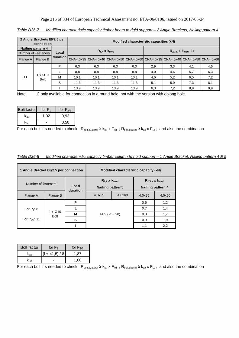
Page 216 of 334 of European Technical Assessment no. ETA-06/0106, issued on 2017-05-24
Table D36-7 Modified characteristic capacity timber beam to rigid support – 2 Angle Brackets, Nailing pattern 4
P 6,3 6,3 6,3 6,3 2,9 3,3 4,1 4,5
L 8,8 8,8 8,8 8,8 4,0 4,6 5,7 6,3
M 10,1 10,1 10,1 10,1 4,6 5,2 6,5 7,2
S 11,3 11,3 11,3 11,3 5,1 5,9 7,3 8,1
I 13,9 13,9 13,9 13,9 6,3 7,2 8,9 9,9
CNA4,0x60
111 x Ø10
Bolt
CNA4,0x40 CNA4,0x50 CNA4,0x60 CNA4,0x35 CNA4,0x40 CNA4,0x50
2 Angle Brackets E6/2.5 per
connectionModified characteristic capacities (kN)
Nailing pattern 4
Load
duration
R1,k x kmod R2/3,k x kmod 1)Number of Fasteners
Flange A Flange B CNA4,0x35
Note: 1) only available for connection in a round hole, not with the version with oblong hole.
Bolt factor for F1 for F2/3
kax 1,02 0,93
klat - 0,50
For each bolt it´s needed to check: Rbolt,d,lateral ≥ klat x Fi,d ; Rbolt,d,axial ≥ kax x Fi,d ; and also the combination
Table D36-8 Modified characteristic capacity timber column to rigid support – 1 Angle Bracket, Nailing pattern 4 & 5
Flange A Flange B 4,0x35 4,0x60
P 0,6 1,2
L 0,7 1,4
M 0,8 1,7
S 0,9 1,9
I 1,1 2,2
Nailing pattern 4
For R1: 8
For R2/3: 11
1 x Ø10
Bolt14,9 / (f + 28)
1 Angle Bracket E6/2.5 per connection Modified characteristic capacity (kN)
Load
duration
4,0x35 4,0x60
Number of fastenersR1,k x kmod R2/3,k x kmod
Nailing pattern5
Bolt factor for F1 for F2/3
kax (f + 41,5) / 8 1,87
klat - 1,00
For each bolt it´s needed to check: Rbolt,d,lateral ≥ klat x Fi,d ; Rbolt,d,axial ≥ kax x Fi,d ; and also the combination

Page 217 of 334 of European Technical Assessment no. ETA-06/0106, issued on 2017-05-24
Table D36-9 Modified characteristic capacity timber column to rigid support – 2 Angle Brackets Nailing pattern 4 & 5
P 2,0 4,0 1,2 2,5
L 2,2 4,6 1,4 2,8
M 2,6 5,3 1,6 3,3
S 3,0 5,9 1,7 3,8
I 3,7 7,3 2,2 4,6
R2/3,k x kmod
Nailing pattern 5 Nailing pattern 4
CNA4,0x60 CNA4,0x35 CNA4,0x60
For R1: 8
For R2/3: 11
1 x Ø10
Bolt
2 Angle Brackets E6/2.5 per
connectionModified characteristic capacities (kN)
Load
duration
Flange A Flange B CNA4,0x35
Number of FastenersR1,k x kmod
Bolt factor for F1 for F2/3
kax 1,02 0,93
klat - 0,50
For each bolt it´s needed to check: Rbolt,d,lateral ≥ klat x Fi,d ; Rbolt,d,axial ≥ kax x Fi,d ; and also the combination
General note to all capacity tables:
b, e and f are in mm.
Wane may not occur under the angle bracket.
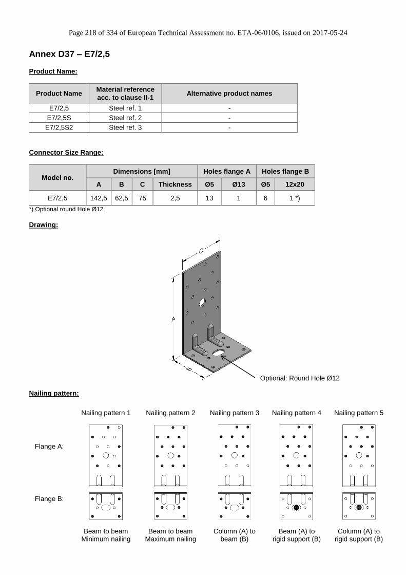
Page 218 of 334 of European Technical Assessment no. ETA-06/0106, issued on 2017-05-24
Annex D37 – E7/2,5
Product Name:
Product Name Material reference
acc. to clause II-1 Alternative product names
E7/2,5 Steel ref. 1 -
E7/2,5S Steel ref. 2 -
E7/2,5S2 Steel ref. 3 -
Connector Size Range:
Model no. Dimensions [mm] Holes flange A Holes flange B
A B C Thickness Ø5 Ø13 Ø5 12x20
E7/2,5 142,5 62,5 75 2,5 13 1 6 1 *)
*) Optional round Hole Ø12
Drawing:
Nailing pattern:
Nailing pattern 1 Nailing pattern 2 Nailing pattern 3 Nailing pattern 4 Nailing pattern 5
Flange A:
Flange B:
Beam to beam
Minimum nailing Beam to beam
Maximum nailing Column (A) to
beam (B) Beam (A) to
rigid support (B) Column (A) to
rigid support (B)
Optional: Round Hole Ø12

Page 219 of 334 of European Technical Assessment no. ETA-06/0106, issued on 2017-05-24
Table D37-1 Modified characteristic capacity timber beam to timber beam – 1 Angle Bracket, Nailing pattern 1
Flange A Flange B 4,0x35 4,0x60
f ≤ 92,8 f ≤ 31,2
f > 92,8 f > 31,2
f ≤ 63,6 f ≤ 24,4
f > 63,6 f > 24,4
f ≤ 48,2 f ≤ 20
f > 48,2 f > 20
f ≤ 38,8 f ≤ 16,8
f > 38,8 f > 16,8
f ≤ 27,7 f ≤ 12,7
f > 27,7 f > 12,7
49 / ( f + 56 ) 97 / ( f + 56 )
20,5 / ( f + 1) 20,5 / ( f + 1)
2,5
65 / ( f + 56 )
20,5 / ( f + 1)
20,5 / ( f + 1)
4,6
59 / ( f + 56 ) 119 / ( f + 56 )
20,5 / ( f + 1) 20,5 / ( f + 1)
2,9
3,4
43/ ( f + 56 ) 87 / ( f + 56 )
3,8
M
S
2,3
4,0x60
1,5
1,7
20,5 / ( f + 1)
Load
duration
1,9
4,0x35
1,3
37 / ( f + 56 ) 75 / ( f + 56)
20,5 / ( f + 1) 20,5 / ( f + 1)
R2/3,k x kmod
32 / ( f + 56 )
Modified characteristic capacity (kN)1 Angle Bracket E7/2.5 per
connection
Nailing pattern 1
Number of fasteners
6 4
R1,k x kmod
I
20,5 / ( f + 1)
P
L

Page 220 of 334 of European Technical Assessment no. ETA-06/0106, issued on 2017-05-24
Table D37-2 Modified characteristic capacity timber beam to timber beam – 1 Angle Bracket, Nailing pattern 2
Flange A Flange B 4,0x35 4,0x60
f ≤ 65,9 f ≤ 25
f > 65,9 f > 25
f ≤ 47,8 f ≤ 19,8
f > 47,8 f > 19,8
f ≤ 37,4 f ≤ 16,3
f > 37,4 f > 16,3
f ≤ 30,6 f ≤ 13,9
f > 30,6 f > 13,9
f ≤ 22,3 f ≤ 10,5
f > 22,3 f > 10,5
1 Angle Bracket E7/2.5 per
connectionModified characteristic capacity (kN)
Nailing pattern 2
Load
duration
R1,k x kmod R2/3,k x kmod
Number of fasteners
4,0x35 4,0x60
13 6
P 2,0 3,7
37 / ( f + 56 ) 75/ ( f + 56 )
20,5 / ( f + 1) 20,5 / ( f + 1)
L 2,3 4,4
43 / ( f + 56 ) 87 / ( f + 56)
20,5 / ( f + 1) 20,5 / ( f + 1)
M 2,6 5,0
49/ ( f + 56 ) 99 / ( f + 56 )
20,5 / ( f + 1) 20,5 / ( f + 1)
S 3,0 5,6
56 / ( f + 56 ) 112 / ( f + 56 )
20,5 / ( f + 1) 20,5 / ( f + 1)
I 3,7 6,9
68 / ( f + 56 ) 136 / ( f + 56 )
20,5 / ( f + 1) 20,5 / ( f + 1)

Page 221 of 334 of European Technical Assessment no. ETA-06/0106, issued on 2017-05-24
Table D37-3 Modified characteristic capacity timber beam to timber beam – 2 Angle Brackets, Nailing pattern 1
P 1,2 1,4 2,3 2,5 2,2 2,4 4,0 4,3
L 1,7 2,0 3,2 3,4 3,0 3,3 5,5 6,0
M 1,9 2,2 3,7 3,9 3,4 3,8 6,3 6,8
S 2,2 2,5 4,1 4,4 3,9 4,2 7,1 7,7
I 2,6 3,1 5,1 5,4 4,7 5,2 8,7 9,4
2 Angle Brackets E7/2.5 per
connectionModified characteristic capacities (kN)
Nailing pattern 1
Load
duration
R1,k x kmod R2/3,k x kmodNumber of Fasteners
Flange A Flange B CNA4,0x35 CNA4,0x60
6 4
CNA4,0x40 CNA4,0x50 CNA4,0x60 CNA4,0x35 CNA4,0x40 CNA4,0x50
Table D37-4 Modified characteristic capacity timber beam to timber beam – 2 Angle Brackets, Nailing pattern 2
P 2,8 3,2 3,6 3,8 5,0 5,5 6,7 7,1
L 3,9 4,4 5,0 5,3 7,0 7,6 9,3 9,9
M 4,4 5,0 5,8 6,1 8,0 8,7 10,6 11,4
S 5,0 5,7 6,5 6,8 9,0 9,8 12,0 12,8
I 6,1 6,9 7,9 8,4 11,0 12,0 14,6 15,6
Flange B CNA4,0x35 CNA4,0x60 CNA4,0x35 CNA4,0x60CNA4,0x40 CNA4,0x50 CNA4,0x40 CNA4,0x50
13 6
2 Angle Brackets E7/2.5 per
connectionModified characteristic capacities (kN)
Nailing pattern 2
Load
duration
R1,k x kmod R2/3,k x kmodNumber of Fasteners
Flange A

Page 222 of 334 of European Technical Assessment no. ETA-06/0106, issued on 2017-05-24
Table D37-5 Modified characteristic capacity timber column to timber beam – 1 Angle Bracket, Nailing pattern 2 & 3
Flange A Flange B 4,0x35 4,0x60
f ≤ 65,9 f ≤ 25
f > 65,9 f > 25
f ≤ 47,8 f ≤ 19,8
f > 47,8 f > 19,8
f ≤ 37,4 f ≤ 16,3
f > 37,4 f > 16,3
f ≤ 30,6 f ≤ 13,9
f > 30,6 f > 13,9
f ≤ 22,3 f ≤ 10,5
f > 22,3 f > 10,5
R1,k x kmod
Nailing pattern 3
R2/3,k x kmod
Nailing pattern 2Number of fasteners
1 Angle Bracket E7/2.5 per connection Modified characteristic capacity (kN)
Load
duration
4,0x35 4,0x60
For R1: 10
For R2/3: 13
6
P 1,8 3,7
37 / ( f + 56 ) 74/ ( f + 56 )
20,5 / ( f + 1) 20,5 / ( f + 1)
L 2,1 4,3
43 / ( f + 56 ) 87 / ( f + 56)
20,5 / ( f + 1) 20,5 / ( f + 1)
M 2,5 4,8
49/ ( f + 56 ) 99 / ( f + 56 )
20,5 / ( f + 1) 20,5 / ( f + 1)
S 2,8 5,5
56 / ( f + 56 ) 112 / ( f + 56 )
20,5 / ( f + 1) 20,5 / ( f + 1)
I 3,4 6,7
68 / ( f + 56 ) 136 / ( f + 56 )
20,5 / ( f + 1) 20,5 / ( f + 1)

Page 223 of 334 of European Technical Assessment no. ETA-06/0106, issued on 2017-05-24
Table D37-6 Modified characteristic capacity timber column to timber beam – 2 Angle Brackets, Nailing pattern 2 &
3
P 2,5 5,0 3,7 7,3
L 2,9 5,8 4,3 8,5
M 3,3 6,7 4,9 9,8
S 3,7 7,5 5,6 10,9
I 4,5 9,2 6,8 13,4
R1,k x kmod
Nailing pattern 3
R2/3,k x kmod
CNA4,0x60 CNA4,0x35 CNA4,0x60
For R1: 10
For R2/3: 13
6
2 Angle Brackets E7/2.5 per
connectionModified characteristic capacities (kN)
Load
durationNailing pattern 2
Flange A Flange B CNA4,0x35
Number of Fasteners
Table D37-7 Modified characteristic capacity timber beam to rigid support – 1 Angle Bracket, Nailing pattern 4
Flange A Flange B 4,0x35 4,0x40 4,0x50 4,0x60 4,0x35 4,0x40 4,0x50 4,0x60
P 0,6 0,7 1,1 1,2
L 0,7 0,8 1,3 1,4
M 0,8 0,9 1,4 1,6
S 0,9 1,0 1,6 1,8
I 1,1 1,2 2,0 2,2
Nailing pattern 4
Number of fastenersR2/3,k x kmod 1)
19,2 / (f + 28)
Load
duration
1 x Ø10
Bolt13
1 Angle Bracket E7/2.5 per
connection
R1,k x kmod
Modified characteristic capacity (kN)
Note: 1) only available for connection in a round hole, not with the version with oblong hole.
Bolt factor for F1 for F2/3
kax (f + 41,5) / 8 1,87
klat - 1,00
For each bolt it´s needed to check: Rbolt,d,lateral ≥ klat x Fi,d ; Rbolt,d,axial ≥ kax x Fi,d ; and also the combination

Page 224 of 334 of European Technical Assessment no. ETA-06/0106, issued on 2017-05-24
Table D37-8 Modified characteristic capacity timber beam to rigid support – 2 Angle Brackets, Nailing pattern 4
P 6,4 6,4 6,4 6,4 2,9 3,3 4,1 4,5
L 8,9 8,9 8,9 8,9 4,0 4,6 5,7 6,3
M 10,2 10,2 10,2 10,2 4,6 5,2 6,5 7,2
S 11,4 11,4 11,4 11,4 5,1 5,9 7,3 8,1
I 14,0 14,0 14,0 14,0 6,3 7,2 8,9 9,9
CNA4,0x60
131 x Ø10
Bolt
CNA4,0x40 CNA4,0x50 CNA4,0x60 CNA4,0x35 CNA4,0x40 CNA4,0x50
2 Angle Brackets E7/2.5 per
connectionModified characteristic capacities (kN)
Nailing pattern 4
Load
duration
R1,k x kmod R2/3,k x kmod 1)Number of Fasteners
Flange A Flange B CNA4,0x35
Note: 1) only available for connection in a round hole, not with the version with oblong hole.
Bolt factor for F1 for F2/3
kax 1,02 0,93
klat - 0,50
For each bolt it´s needed to check: Rbolt,d,lateral ≥ klat x Fi,d ; Rbolt,d,axial ≥ kax x Fi,d ; and also the combination
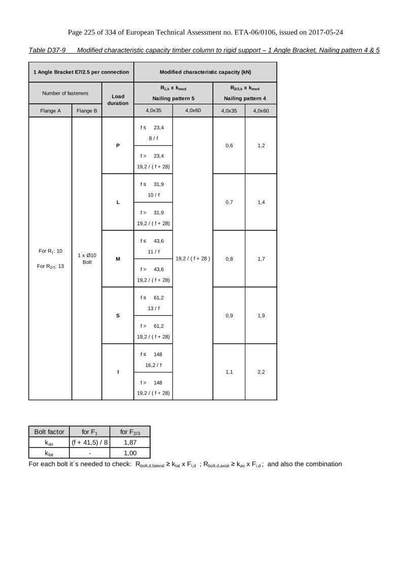
Page 225 of 334 of European Technical Assessment no. ETA-06/0106, issued on 2017-05-24
Table D37-9 Modified characteristic capacity timber column to rigid support – 1 Angle Bracket, Nailing pattern 4 & 5
Flange A Flange B 4,0x35 4,0x60
f ≤ 23,4
f > 23,4
f ≤ 31,9
f > 31,9
f ≤ 43,6
f > 43,6
f ≤ 61,2
f > 61,2
f ≤ 148
f > 148
Nailing pattern 5 Nailing pattern 4
4,0x35
L 0,7 1,4
1 Angle Bracket E7/2.5 per connection Modified characteristic capacity (kN)
Number of fastenersLoad
duration
R1,k x kmod R2/3,k x kmod
4,0x60
19,2 / ( f + 28)
M 0,8
0,9
For R1: 10
For R2/3: 13
1 x Ø10
Bolt
P 0,6
8 / f
I 1,1 2,2
16,2 / f
19,2 / ( f + 28)
S 1,9
13 / f
1,7
11 / f
19,2 / ( f + 28)
19,2 / ( f + 28 )
10 / f
19,2 / ( f + 28)
1,2
19,2 / ( f + 28)
Bolt factor for F1 for F2/3
kax (f + 41,5) / 8 1,87
klat - 1,00
For each bolt it´s needed to check: Rbolt,d,lateral ≥ klat x Fi,d ; Rbolt,d,axial ≥ kax x Fi,d ; and also the combination

Page 226 of 334 of European Technical Assessment no. ETA-06/0106, issued on 2017-05-24
Table D37-10 Modified characteristic capacity timber column to rigid support – 2 Angle Brackets, Nailing pattern 4 &
5
P 2,0 4,0 1,1 2,5
L 2,3 4,6 1,4 2,8
M 2,6 5,3 1,6 3,3
S 3,0 6,0 1,8 3,7
I 3,7 7,3 2,2 4,6
R2/3,k x kmod
Nailing pattern 5 Nailing pattern 4
CNA4,0x60 CNA4,0x35 CNA4,0x60
For R1: 10
For R2/3: 13
1 x Ø10
Bolt
2 Angle Brackets E7/2.5 per
connectionModified characteristic capacities (kN)
Load
duration
Flange A Flange B CNA4,0x35
Number of FastenersR1,k x kmod
Bolt factor for F1 for F2/3
kax 1,02 0,93
klat - 0,50
For each bolt it´s needed to check: Rbolt,d,lateral ≥ klat x Fi,d ; Rbolt,d,axial ≥ kax x Fi,d ; and also the combination
General note to all capacity tables:
b, e and f are in mm.
Wane may not occur under the angle bracket.
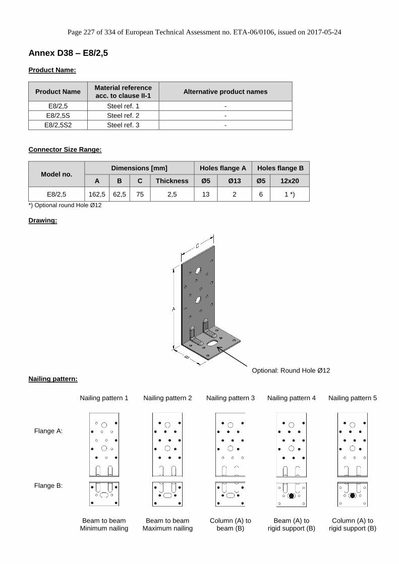
Page 227 of 334 of European Technical Assessment no. ETA-06/0106, issued on 2017-05-24
Annex D38 – E8/2,5
Product Name:
Product Name Material reference
acc. to clause II-1 Alternative product names
E8/2,5 Steel ref. 1 -
E8/2,5S Steel ref. 2 -
E8/2,5S2 Steel ref. 3 -
Connector Size Range:
Model no. Dimensions [mm] Holes flange A Holes flange B
A B C Thickness Ø5 Ø13 Ø5 12x20
E8/2,5 162,5 62,5 75 2,5 13 2 6 1 *)
*) Optional round Hole Ø12
Drawing:
Nailing pattern:
Nailing pattern 1 Nailing pattern 2 Nailing pattern 3 Nailing pattern 4 Nailing pattern 5
Flange A:
Flange B:
Beam to beam
Minimum nailing Beam to beam
Maximum nailing Column (A) to
beam (B) Beam (A) to
rigid support (B) Column (A) to
rigid support (B)
Optional: Round Hole Ø12

Page 228 of 334 of European Technical Assessment no. ETA-06/0106, issued on 2017-05-24
Table D38-1 Modified characteristic capacity timber beam to timber beam – 1 Angle Bracket, Nailing pattern 1
Flange A Flange B 4,0x35 4,0x60
f ≤ 92,8 f ≤ 31,2
f > 92,8 f > 31,2
f ≤ 63,6 f ≤ 24,4
f > 63,6 f > 24,4
f ≤ 48,2 f ≤ 20
f > 48,2 f > 20
f ≤ 38,8 f ≤ 16,8
f > 38,8 f > 16,8
f ≤ 27,7 f ≤ 12,7
f > 27,7 f > 12,7
1 Angle Bracket E8/2.5 per
connection
Nailing pattern 1
Number of fasteners
6 4
R1,k x kmod
I
20,5 / ( f + 1)
P
L
1,3
37 / ( f + 56 ) 75 / ( f + 56)
20,5 / ( f + 1) 20,5 / ( f + 1)
R2/3,k x kmod
32 / ( f + 56 )
Modified characteristic capacity (kN)
M
S
2,3
4,0x60
1,5
1,7
20,5 / ( f + 1)
Load
duration
1,9
4,0x35
4,6
59 / ( f + 56 ) 119 / ( f + 56 )
20,5 / ( f + 1) 20,5 / ( f + 1)
2,9
3,4
43/ ( f + 56 ) 87 / ( f + 56 )
3,8
49 / ( f + 56 ) 97 / ( f + 56 )
20,5 / ( f + 1) 20,5 / ( f + 1)
2,5
65 / ( f + 56 )
20,5 / ( f + 1)
20,5 / ( f + 1)
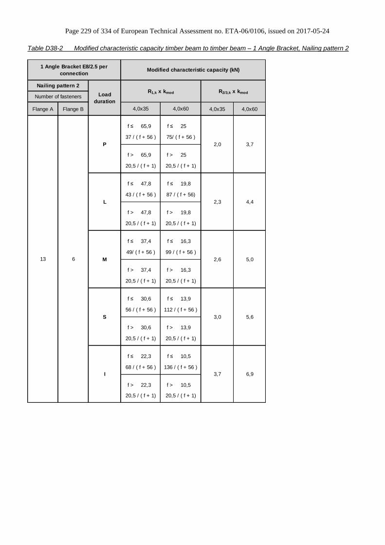
Page 229 of 334 of European Technical Assessment no. ETA-06/0106, issued on 2017-05-24
Table D38-2 Modified characteristic capacity timber beam to timber beam – 1 Angle Bracket, Nailing pattern 2
Flange A Flange B 4,0x35 4,0x60
f ≤ 65,9 f ≤ 25
f > 65,9 f > 25
f ≤ 47,8 f ≤ 19,8
f > 47,8 f > 19,8
f ≤ 37,4 f ≤ 16,3
f > 37,4 f > 16,3
f ≤ 30,6 f ≤ 13,9
f > 30,6 f > 13,9
f ≤ 22,3 f ≤ 10,5
f > 22,3 f > 10,5
I 3,7 6,9
68 / ( f + 56 ) 136 / ( f + 56 )
20,5 / ( f + 1) 20,5 / ( f + 1)
S 3,0 5,6
56 / ( f + 56 ) 112 / ( f + 56 )
20,5 / ( f + 1) 20,5 / ( f + 1)
M 2,6 5,0
49/ ( f + 56 ) 99 / ( f + 56 )
20,5 / ( f + 1) 20,5 / ( f + 1)
2,3 4,4
43 / ( f + 56 ) 87 / ( f + 56)
20,5 / ( f + 1) 20,5 / ( f + 1)
13 6
P 2,0 3,7
37 / ( f + 56 ) 75/ ( f + 56 )
20,5 / ( f + 1) 20,5 / ( f + 1)
L
1 Angle Bracket E8/2.5 per
connectionModified characteristic capacity (kN)
Nailing pattern 2
Load
duration
R1,k x kmod R2/3,k x kmod
Number of fasteners
4,0x35 4,0x60

Page 230 of 334 of European Technical Assessment no. ETA-06/0106, issued on 2017-05-24
Table D38-3 Modified characteristic capacity timber beam to timber beam – 2 Angle Brackets, Nailing pattern 1
P 1,2 1,4 2,3 2,5 2,2 2,4 4,0 4,3
L 1,7 2,0 3,2 3,4 3,0 3,3 5,5 6,0
M 1,9 2,2 3,7 3,9 3,4 3,8 6,3 6,8
S 2,2 2,5 4,1 4,4 3,9 4,2 7,1 7,7
I 2,6 3,1 5,1 5,4 4,7 5,2 8,7 9,4
CNA4,0x60
6 4
CNA4,0x40 CNA4,0x50 CNA4,0x60 CNA4,0x35 CNA4,0x40 CNA4,0x50
2 Angle Brackets E8/2.5 per
connectionModified characteristic capacities (kN)
Nailing pattern 1
Load
duration
R1,k x kmod R2/3,k x kmodNumber of Fasteners
Flange A Flange B CNA4,0x35
Table D38-4 Modified characteristic capacity timber beam to timber beam – 2 Angle Brackets E8/2,5
Nailing pattern 2
P 2,8 3,2 3,6 3,8 5,0 5,5 6,7 7,1
L 3,9 4,4 5,0 5,3 7,0 7,6 9,3 9,9
M 4,4 5,0 5,8 6,1 8,0 8,7 10,6 11,4
S 5,0 5,7 6,5 6,8 9,0 9,8 12,0 12,8
I 6,1 6,9 7,9 8,4 11,0 12,0 14,6 15,6
13 6
2 Angle Brackets E8/2.5 per
connectionModified characteristic capacities (kN)
Nailing pattern 2
Load
duration
R1,k x kmod R2/3,k x kmodNumber of Fasteners
Flange A Flange B CNA4,0x35 CNA4,0x60 CNA4,0x35 CNA4,0x60CNA4,0x40 CNA4,0x50 CNA4,0x40 CNA4,0x50

Page 231 of 334 of European Technical Assessment no. ETA-06/0106, issued on 2017-05-24
Table D38-5 Modified characteristic capacity timber column to timber beam – 1 Angle Bracket, Nailing pattern 2 & 3
Flange A Flange B 4,0x35 4,0x60
f ≤ 65,9 f ≤ 25
f > 65,9 f > 25
f ≤ 47,8 f ≤ 19,8
f > 47,8 f > 19,8
f ≤ 37,4 f ≤ 16,3
f > 37,4 f > 16,3
f ≤ 30,6 f ≤ 13,9
f > 30,6 f > 13,9
f ≤ 22,3 f ≤ 10,5
f > 22,3 f > 10,5
I 3,4 6,7
68 / ( f + 56 ) 136 / ( f + 56 )
20,5 / ( f + 1) 20,5 / ( f + 1)
S 2,8 5,5
56 / ( f + 56 ) 112 / ( f + 56 )
20,5 / ( f + 1) 20,5 / ( f + 1)
M 2,5 4,8
49/ ( f + 56 ) 99 / ( f + 56 )
20,5 / ( f + 1) 20,5 / ( f + 1)
L 2,1 4,3
43 / ( f + 56 ) 87 / ( f + 56)
20,5 / ( f + 1) 20,5 / ( f + 1)
4,0x60
For R1: 10
For R2/3: 13
6
P 1,8 3,7
37 / ( f + 56 ) 74/ ( f + 56 )
20,5 / ( f + 1) 20,5 / ( f + 1)
R1,k x kmod
Nailing pattern 3
R2/3,k x kmod
Nailing pattern 2Number of fasteners
1 Angle Bracket E8/2.5 per connection Modified characteristic capacity (kN)
Load
duration
4,0x35
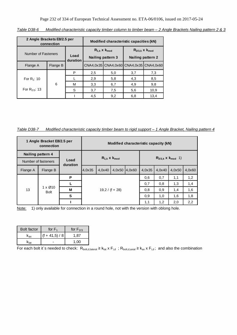
Page 232 of 334 of European Technical Assessment no. ETA-06/0106, issued on 2017-05-24
Table D38-6 Modified characteristic capacity timber column to timber beam – 2 Angle Brackets Nailing pattern 2 & 3
P 2,5 5,0 3,7 7,3
L 2,9 5,8 4,3 8,5
M 3,3 6,7 4,9 9,8
S 3,7 7,5 5,6 10,9
I 4,5 9,2 6,8 13,4
For R1: 10
For R2/3: 13
6
2 Angle Brackets E8/2.5 per
connectionModified characteristic capacities (kN)
Load
durationNailing pattern 2
Flange A Flange B CNA4,0x35
Number of FastenersR1,k x kmod
Nailing pattern 3
R2/3,k x kmod
CNA4,0x60 CNA4,0x35 CNA4,0x60
Table D38-7 Modified characteristic capacity timber beam to rigid support – 1 Angle Bracket, Nailing pattern 4
Flange A Flange B 4,0x35 4,0x40 4,0x50 4,0x60 4,0x35 4,0x40 4,0x50 4,0x60
P 0,6 0,7 1,1 1,2
L 0,7 0,8 1,3 1,4
M 0,8 0,9 1,4 1,6
S 0,9 1,0 1,6 1,8
I 1,1 1,2 2,0 2,2
Modified characteristic capacity (kN)
Nailing pattern 4
Number of fastenersR2/3,k x kmod 1)
19,2 / (f + 28)
Load
duration
1 x Ø10
Bolt13
1 Angle Bracket E8/2.5 per
connection
R1,k x kmod
Note: 1) only available for connection in a round hole, not with the version with oblong hole.
Bolt factor for F1 for F2/3
kax (f + 41,5) / 8 1,87
klat - 1,00
For each bolt it´s needed to check: Rbolt,d,lateral ≥ klat x Fi,d ; Rbolt,d,axial ≥ kax x Fi,d ; and also the combination

Page 233 of 334 of European Technical Assessment no. ETA-06/0106, issued on 2017-05-24
Table D38-8 Modified characteristic capacity timber beam to rigid support – 2 Angle Brackets, Nailing pattern 4
P 6,4 6,4 6,4 6,4 2,9 3,3 4,1 4,5
L 8,9 8,9 8,9 8,9 4,0 4,6 5,7 6,3
M 10,2 10,2 10,2 10,2 4,6 5,2 6,5 7,2
S 11,4 11,4 11,4 11,4 5,1 5,9 7,3 8,1
I 14,0 14,0 14,0 14,0 6,3 7,2 8,9 9,9
2 Angle Brackets E8/2.5 per
connectionModified characteristic capacities (kN)
Nailing pattern 4
Load
duration
R1,k x kmod R2/3,k x kmod 1)Number of Fasteners
Flange A Flange B CNA4,0x35 CNA4,0x60
131 x Ø10
Bolt
CNA4,0x40 CNA4,0x50 CNA4,0x60 CNA4,0x35 CNA4,0x40 CNA4,0x50
Note: 1) only available for connection in a round hole, not with the version with oblong hole.
Bolt factor for F1 for F2/3
kax 1,02 0,93
klat - 0,50
For each bolt it´s needed to check: Rbolt,d,lateral ≥ klat x Fi,d ; Rbolt,d,axial ≥ kax x Fi,d ; and also the combination

Page 234 of 334 of European Technical Assessment no. ETA-06/0106, issued on 2017-05-24
Table D38-9 Modified characteristic capacity timber column to rigid support – 1 Angle Bracket, Nailing pattern 4 & 5
Flange A Flange B 4,0x35 4,0x60
f ≤ 23,4
f > 23,4
f ≤ 31,9
f > 31,9
f ≤ 43,6
f > 43,6
f ≤ 61,2
f > 61,2
f ≤ 148
f > 148
1,7
11 / f
19,2 / ( f + 28)
19,2 / ( f + 28 )
10 / f
19,2 / ( f + 28)
1,2
19,2 / ( f + 28)
1,1 2,2
16,2 / f
19,2 / ( f + 28)
S 1,9
13 / f
19,2 / ( f + 28)
M 0,8
0,9
For R1: 10
For R2/3: 13
1 x Ø10
Bolt
P 0,6
8 / f
I
1 Angle Bracket E8/2.5 per connection Modified characteristic capacity (kN)
Number of fastenersLoad
duration
R1,k x kmod R2/3,k x kmod
4,0x60
Nailing pattern 5 Nailing pattern 4
4,0x35
L 0,7 1,4
Bolt factor for F1 for F2/3
kax (f + 41,5) / 8 1,87
klat - 1,00
For each bolt it´s needed to check: Rbolt,d,lateral ≥ klat x Fi,d ; Rbolt,d,axial ≥ kax x Fi,d ; and also the combination
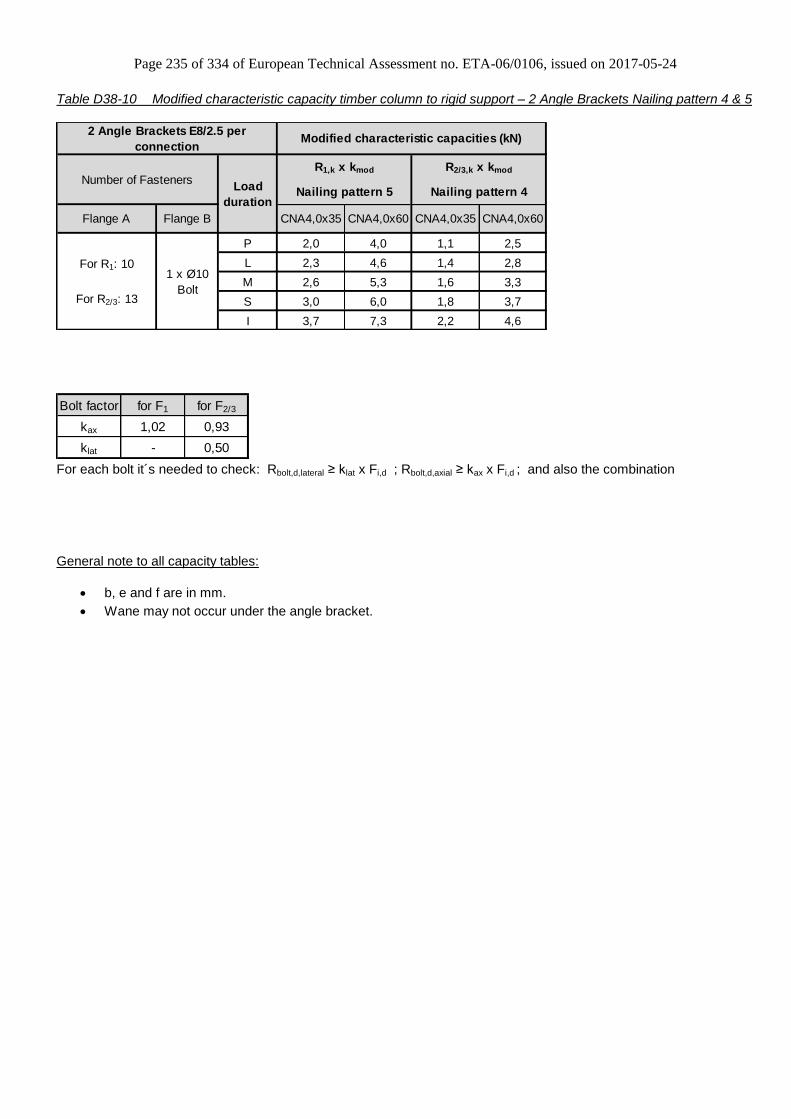
Page 235 of 334 of European Technical Assessment no. ETA-06/0106, issued on 2017-05-24
Table D38-10 Modified characteristic capacity timber column to rigid support – 2 Angle Brackets Nailing pattern 4 & 5
P 2,0 4,0 1,1 2,5
L 2,3 4,6 1,4 2,8
M 2,6 5,3 1,6 3,3
S 3,0 6,0 1,8 3,7
I 3,7 7,3 2,2 4,6
For R1: 10
For R2/3: 13
1 x Ø10
Bolt
2 Angle Brackets E8/2.5 per
connectionModified characteristic capacities (kN)
Load
duration
Flange A Flange B CNA4,0x35
Number of FastenersR1,k x kmod R2/3,k x kmod
Nailing pattern 5 Nailing pattern 4
CNA4,0x60 CNA4,0x35 CNA4,0x60
Bolt factor for F1 for F2/3
kax 1,02 0,93
klat - 0,50
For each bolt it´s needed to check: Rbolt,d,lateral ≥ klat x Fi,d ; Rbolt,d,axial ≥ kax x Fi,d ; and also the combination
General note to all capacity tables:
b, e and f are in mm.
Wane may not occur under the angle bracket.
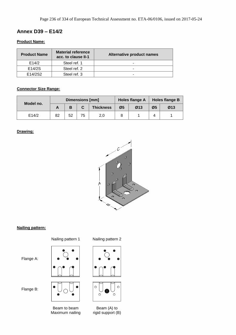
Page 236 of 334 of European Technical Assessment no. ETA-06/0106, issued on 2017-05-24
Annex D39 – E14/2
Product Name:
Product Name Material reference
acc. to clause II-1 Alternative product names
E14/2 Steel ref. 1 -
E14/2S Steel ref. 2 -
E14/2S2 Steel ref. 3 -
Connector Size Range:
Model no. Dimensions [mm] Holes flange A Holes flange B
A B C Thickness Ø5 Ø13 Ø5 Ø13
E14/2 82 52 75 2,0 8 1 4 1
Drawing:
Nailing pattern:
Nailing pattern 1 Nailing pattern 2
Flange A:
Flange B:
Beam to beam
Maximum nailing Beam (A) to
rigid support (B)

Page 237 of 334 of European Technical Assessment no. ETA-06/0106, issued on 2017-05-24
Table D39-1 Modified characteristic capacity timber beam to timber beam – 1 Angle Bracket, Nailing pattern 1
Flange A Flange B 4,0x35 4,0x60
f ≤ 65,3 f ≤ 21,6
f > 65,3 f > 21,6
f ≤ 44,5 f ≤ 16,9
f > 44,5 f > 16,9
f ≤ 33,6 f ≤ 13,8
f > 33,6 f > 13,8
f ≤ 27 f ≤ 11,6
f > 27 f > 11,6
f ≤ 19,2 f ≤ 8,7
f > 19,2 f > 8,7
31 / ( f + 39 ) 61 / ( f + 39 )
13,1 / ( f + 1) 13,1 / ( f + 1)
2,8
40 / ( f + 39 )
13,1 / ( f + 1)
13,1 / ( f + 1)
5,3
37 / ( f + 39 ) 75 / ( f + 39 )
13,1 / ( f + 1) 13,1 / ( f + 1)
3,4
3,8
27/ ( f + 39 ) 54 / ( f + 39 )
4,4
M
S
2,9
4,0x60
1,8
2,1
13,1 / ( f + 1)
Load
duration
2,4
4,0x35
1,6
23 / ( f + 39 ) 47 / ( f + 39)
13,1 / ( f + 1) 13,1 / ( f + 1)
R2/3,k x kmod
20 / ( f + 39 )
Modified characteristic capacity (kN)1 Angle Bracket E14/2 per
connection
Nailing pattern 1
Number of fasteners
4 8
R1,k x kmod
I
13,1 / ( f + 1)
P
L

Page 238 of 334 of European Technical Assessment no. ETA-06/0106, issued on 2017-05-24
Table D39-2 Modified characteristic capacity timber beam to timber beam – 2 Angle Brackets, Nailing pattern 1
P 2,5 5,0 3,2 5,8
L 2,9 5,8 3,7 6,8
M 3,3 6,7 4,3 7,7
S 3,7 7,5 4,8 8,7
I 4,5 9,2 5,9 10,7
Number of Fasteners
Flange A Flange B CNA4,0x35 CNA4,0x60
4 8
CNA4,0x60 CNA4,0x35
2 Angle Brackets E14/2 per
connectionModified characteristic capacities (kN)
Nailing pattern 1
Load
duration
R1,k x kmod R2/3,k x kmod
Table D39-3 Modified characteristic capacity timber beam to rigid support – 1 Angle Bracket E14/2
Nailing pattern 2
Flange A Flange B 4,0x35 4,0x60 4,0x35 4,0x60
P 1,0 2,0
L 1,1 2,4
M 1,4 2,8
S 1,5 3,1
I 1,8 8,0
Min of:
26,5 / (f + 17)
11,3 / f
Load
duration
1 x Ø12
Bolt8
1 Angle Bracket E14/2 per
connection
R1,k x kmod
Modified characteristic capacity
(kN)
Nailing pattern 2
Number of fastenersR2/3,k x kmod
Bolt factor for F1 for F2/3
kax (f + 33) / 9 1,04
klat - 1,00
For each bolt it´s needed to check: Rbolt,d,lateral ≥ klat x Fi,d ; Rbolt,d,axial ≥ kax x Fi,d ; and also the combination

Page 239 of 334 of European Technical Assessment no. ETA-06/0106, issued on 2017-05-24
Table D39-4 Modified characteristic capacity timber beam to rigid support – 2 Angle Brackets, Nailing pattern 2
P 2,1 4,2 2,0 4,2
L 2,5 4,9 2,3 4,8
M 2,8 5,6 2,7 5,5
S 3,2 6,4 3,1 6,3
I 3,9 6,9 3,7 7,6
81 x Ø12
Bolt
CNA4,0x60 CNA4,0x35
2 Angle Brackets E14/2 per
connectionModified characteristic capacities (kN)
Nailing pattern 2
Load
duration
R1,k x kmod R2/3,k x kmodNumber of Fasteners
Flange A Flange B CNA4,0x35 CNA4,0x60
Bolt factor for F1 for F2/3
kax 0,99 0,52
klat - 0,50
For each bolt it´s needed to check: Rbolt,d,lateral ≥ klat x Fi,d ; Rbolt,d,axial ≥ kax x Fi,d ; and also the combination
General note to all capacity tables:
b, e and f are in mm.
Wane may not occur under the angle bracket.

Page 240 of 334 of European Technical Assessment no. ETA-06/0106, issued on 2017-05-24
Annex D40 – E17/2
Product Name:
Product Name Material reference
acc. to clause II-1 Alternative product names
E17/2 Steel ref. 1 -
E17/2S Steel ref. 2 -
E17/2S2 Steel ref. 3 -
Connector Size Range:
Model no. Dimensions [mm] Holes flange A Holes flange B
A B C Thickness Ø5 Ø13 Ø5 Ø13
E17/2 152 52 75 2,0 15 2 4 1
Drawing:
Nailing pattern:
Nailing pattern 1 Nailing pattern 2 Nailing pattern 3 Nailing pattern 4 Nailing pattern 5
Flange A:
Flange B:
Beam to beam
Minimum nailing Beam to beam
Maximum nailing Column (A) to
beam (B) Beam (A) to
rigid support (B) Column (A) to
rigid support (B)

Page 241 of 334 of European Technical Assessment no. ETA-06/0106, issued on 2017-05-24
Table D40-1 Modified characteristic capacity timber beam to timber beam – 1 Angle Bracket, Nailing pattern 1
Flange A Flange B 4,0x35 4,0x60
f ≤ 65,3 f ≤ 21,6
f > 65,3 f > 21,6
f ≤ 44,5 f ≤ 16,9
f > 44,5 f > 16,9
f ≤ 33,6 f ≤ 13,8
f > 33,6 f > 13,8
f ≤ 27 f ≤ 11,6
f > 27 f > 11,6
f ≤ 19,2 f ≤ 8,7
f > 19,2 f > 8,7
31 / ( f + 39 ) 61 / ( f + 39 )
13,1 / ( f + 1) 13,1 / ( f + 1)
2,3
40 / ( f + 39 )
13,1 / ( f + 1)
13,1 / ( f + 1)
4,3
37 / ( f + 39 ) 75 / ( f + 39 )
13,1 / ( f + 1) 13,1 / ( f + 1)
2,7
3,1
27 / ( f + 39 ) 54 / ( f + 39 )
3,5
M
S
2,3
4,0x60
1,4
1,7
13,1 / ( f + 1)
Load
duration
1,9
4,0x35
1,2
23 / ( f + 39 ) 47 / ( f + 39)
13,1 / ( f + 1) 13,1 / ( f + 1)
R2/3,k x kmod
20 / ( f + 39 )
Modified characteristic capacity (kN)1 Angle Bracket E17/2 per
connection
Nailing pattern 1
Number of fasteners
6 4
R1,k x kmod
I
13,1 / ( f + 1)
P
L

Page 242 of 334 of European Technical Assessment no. ETA-06/0106, issued on 2017-05-24
Table D40-2 Modified characteristic capacity timber beam to timber beam – 1 Angle Bracket, Nailing pattern 2
Flange A Flange B 4,0x35 4,0x60
f ≤ 65,3 f ≤ 21,6
f > 65,3 f > 21,6
f ≤ 44,5 f ≤ 16,9
f > 44,5 f > 16,9
f ≤ 33,6 f ≤ 13,8
f > 33,6 f > 13,8
f ≤ 27 f ≤ 11,6
f > 27 f > 11,6
f ≤ 19,2 f ≤ 8,7
f > 19,2 f > 8,7
1 Angle Bracket E17/2 per
connectionModified characteristic capacity (kN)
Nailing pattern 2
Load
duration
R1,k x kmod R2/3,k x kmod
Number of fasteners
4,0x35 4,0x60
15 4
P 2,1 3,6
20 / ( f + 39 ) 40 / ( f + 39 )
13,1 / ( f + 1) 13,1 / ( f + 1)
L 2,4 4,1
23 / ( f + 39 ) 47 / ( f + 39)
13,1 / ( f + 1) 13,1 / ( f + 1)
M 2,8 4,7
37 / ( f + 39 ) 54 / ( f + 39 )
13,1 / ( f + 1) 13,1 / ( f + 1)
S 3,1 5,3
31 / ( f + 39 ) 61 / ( f + 39 )
13,1 / ( f + 1) 13,1 / ( f + 1)
I 3,8 6,5
37 / ( f + 39 ) 75 / ( f + 39 )
13,1 / ( f + 1) 13,1 / ( f + 1)

Page 243 of 334 of European Technical Assessment no. ETA-06/0106, issued on 2017-05-24
Table D40-3 Modified characteristic capacity timber beam to timber beam – 2 Angle Brackets, Nailing pattern 1
P 2,1 2,4 3,8 4,2 2,2 2,4 3,7 3,9
L 2,9 3,3 5,3 5,8 3,0 3,3 5,1 5,5
M 3,3 3,8 6,0 6,6 3,4 3,8 5,8 6,2
S 3,7 4,2 6,8 7,5 3,9 4,2 6,6 7,0
I 4,5 5,2 8,3 9,1 4,7 5,2 8,0 8,6
2 Angle Brackets E17/2 per
connectionModified characteristic capacities (kN)
Nailing pattern 1
Load
duration
R1,k x kmod R2/3,k x kmodNumber of Fasteners
Flange A Flange B CNA4,0x35 CNA4,0x60
6 4
CNA4,0x40 CNA4,0x50 CNA4,0x60 CNA4,0x35 CNA4,0x40 CNA4,0x50
Table D40-4 Modified characteristic capacity timber beam to timber beam – 2 Angle Brackets, Nailing pattern 2
P 2,5 2,8 3,4 3,7 4,1 4,5 5,5 5,8
L 3,4 3,9 4,7 5,2 5,7 6,3 7,6 8,1
M 3,9 4,5 5,4 5,9 6,6 7,2 8,7 9,3
S 4,4 5,0 6,0 6,7 7,4 8,1 9,8 10,4
I 5,4 6,2 7,4 8,1 9,0 9,9 12,0 12,8
Flange B CNA4,0x35 CNA4,0x60 CNA4,0x35 CNA4,0x60CNA4,0x40 CNA4,0x50 CNA4,0x40 CNA4,0x50
15 4
2 Angle Brackets E17/2 per
connectionModified characteristic capacities (kN)
Nailing pattern 2
Load
duration
R1,k x kmod R2/3,k x kmodNumber of Fasteners
Flange A

Page 244 of 334 of European Technical Assessment no. ETA-06/0106, issued on 2017-05-24
Table D40-5 Modified characteristic capacity timber column to timber beam – 1 Angle Bracket, Nailing pattern 3
Flange A Flange B 4,0x35 4,0x60
f ≤ 65,3 f ≤ 21,6
f > 65,3 f > 21,6
f ≤ 44,5 f ≤ 16,9
f > 44,5 f > 16,9
f ≤ 33,6 f ≤ 13,8
f > 33,6 f > 13,8
f ≤ 27 f ≤ 11,6
f > 27 f > 11,6
f ≤ 19,2 f ≤ 8,7
f > 19,2 f > 8,7
1 Angle Bracket E17/2 per
connectionModified characteristic capacity (kN)
Nailing pattern 3
Load
duration
R1,k x kmod R2/3,k x kmod
Number of fasteners
4,0x35 4,0x60
12 4
P 2,0 3,4
21 / ( f + 39 ) 40 / ( f + 39 )
13,1 / ( f + 1) 13,1 / ( f + 1)
L 2,3 4
23 / ( f + 39 ) 47 / ( f + 39)
13,1 / ( f + 1) 13,1 / ( f + 1)
M 2,6 4,6
27 / ( f + 39 ) 54 / ( f + 39 )
13,1 / ( f + 1) 13,1 / ( f + 1)
S 3,0 5,1
31 / ( f + 39 ) 61 / ( f + 39 )
13,1 / ( f + 1) 13,1 / ( f + 1)
I 3,7 6,3
37 / ( f + 39 ) 75 / ( f + 39 )
13,1 / ( f + 1) 13,1 / ( f + 1)
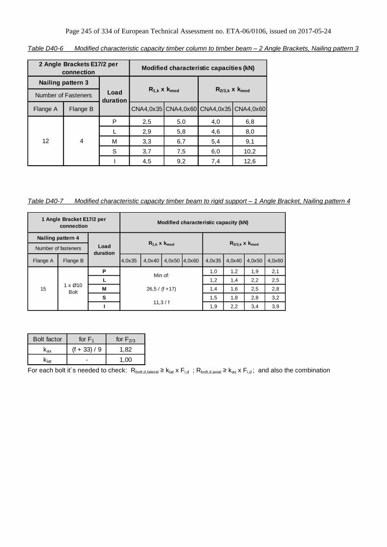
Page 245 of 334 of European Technical Assessment no. ETA-06/0106, issued on 2017-05-24
Table D40-6 Modified characteristic capacity timber column to timber beam – 2 Angle Brackets, Nailing pattern 3
P 2,5 5,0 4,0 6,8
L 2,9 5,8 4,6 8,0
M 3,3 6,7 5,4 9,1
S 3,7 7,5 6,0 10,2
I 4,5 9,2 7,4 12,6
2 Angle Brackets E17/2 per
connectionModified characteristic capacities (kN)
Load
duration
Flange A Flange B CNA4,0x35 CNA4,0x60 CNA4,0x35 CNA4,0x60
Number of Fasteners
Nailing pattern 3R1,k x kmod R2/3,k x kmod
12 4
Table D40-7 Modified characteristic capacity timber beam to rigid support – 1 Angle Bracket, Nailing pattern 4
Flange A Flange B 4,0x35 4,0x40 4,0x50 4,0x60 4,0x35 4,0x40 4,0x50 4,0x60
P 1,0 1,2 1,9 2,1
L 1,2 1,4 2,2 2,5
M 1,4 1,6 2,5 2,8
S 1,5 1,8 2,8 3,2
I 1,9 2,2 3,4 3,9
Nailing pattern 4
Number of fastenersR2/3,k x kmod
Min of:
26,5 / (f +17)
11,3 / f
Load
duration
1 x Ø10
Bolt15
1 Angle Bracket E17/2 per
connection
R1,k x kmod
Modified characteristic capacity (kN)
Bolt factor for F1 for F2/3
kax (f + 33) / 9 1,82
klat - 1,00
For each bolt it´s needed to check: Rbolt,d,lateral ≥ klat x Fi,d ; Rbolt,d,axial ≥ kax x Fi,d ; and also the combination
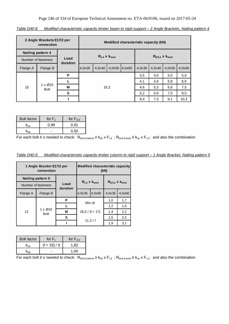
Page 246 of 334 of European Technical Assessment no. ETA-06/0106, issued on 2017-05-24
Table D40-8 Modified characteristic capacity timber beam to rigid support – 2 Angle Brackets, Nailing pattern 4
Flange A Flange B 4,0x35 4,0x40 4,0x50 4,0x60 4,0x35 4,0x40 4,0x50 4,0x60
P 3,5 4,0 5,0 5,6
L 4,1 4,6 5,8 6,6
M 4,6 5,3 6,6 7,5
S 5,2 5,9 7,5 8,5
I 6,4 7,3 9,1 10,3
Number of fasteners
151 x Ø10
Bolt15,2
2 Angle Brackets E17/2 per
connectionModified characteristic capacity (kN)
Nailing pattern 4
Load
duration
R1,k x kmod R2/3,k x kmod
Bolt factor for F1 for F2/3
kax 0,99 0,91
klat - 0,50
For each bolt it´s needed to check: Rbolt,d,lateral ≥ klat x Fi,d ; Rbolt,d,axial ≥ kax x Fi,d ; and also the combination
Table D40-9 Modified characteristic capacity timber column to rigid support – 1 Angle Bracket, Nailing pattern 5
Flange A Flange B 4,0x35 4,0x60 4,0x35 4,0x60
P 1,0 1,7
L 1,2 1,9
M 1,4 2,2
S 1,5 2,5
I 1,9 3,1
Number of fasteners
121 x Ø10
Bolt
Min of:
26,5 / (f + 17)
11,3 / f
1 Angle Bracket E17/2 per
connection
Modified characteristic capacity
(kN)
Nailing pattern 5
Load
duration
R1,k x kmod R2/3,k x kmod
Bolt factor for F1 for F2/3
kax (f + 33) / 9 1,82
klat - 1,00
For each bolt it´s needed to check: Rbolt,d,lateral ≥ klat x Fi,d ; Rbolt,d,axial ≥ kax x Fi,d ; and also the combination

Page 247 of 334 of European Technical Assessment no. ETA-06/0106, issued on 2017-05-24
Table D40-10 Modified characteristic capacity timber column to rigid support – 2 Angle Brackets, Nailing pattern 5
P 6,1 11,7 2,0 3,4
L 7,1 13,6 2,4 3,9
M 8,2 14,2 2,8 4,5
S 9,2 14,2 3,1 5,1
I 11,2 14,2 3,8 6,2
R2/3,k x kmod
Number of Fasteners
Flange A Flange B CNA4,0x35 CNA4,0x60 CNA4,0x35 CNA4,0x60
121 x Ø10
Bolt
2 Angle Brackets E17/2 per
connectionModified characteristic capacities (kN)
Nailing pattern 5
Load
duration
R1,k x kmod
Bolt factor for F1 for F2/3
kax 0,99 0,91
klat - 0,50
For each bolt it´s needed to check: Rbolt,d,lateral ≥ klat x Fi,d ; Rbolt,d,axial ≥ kax x Fi,d ; and also the combination
General notes to all capacity tables:
b, e and f are in mm.
Wane may not occur under the angle bracket.

Page 248 of 334 of European Technical Assessment no. ETA-06/0106, issued on 2017-05-24
Annex D41 – E18/2,5
Product Name:
Product Name Material reference
acc. to clause II-1 Alternative product names
E18/2,5 Steel ref. 1 -
E18/2,5S Steel ref. 2 -
E18/2,5S2 Steel ref. 3 -
Connector Size Range:
Model no. Dimensions [mm] Holes flange A Holes flange B
A B C Thickness Ø5 Ø13 Ø5 Ø13
E18/2,5 152,5 52,5 75 2,5 15 2 4 1
Drawing:
Nailing pattern:
Nailing pattern 1 Nailing pattern 2 Nailing pattern 3 Nailing pattern 4 Nailing pattern 5
Flange A:
Flange B:
Beam to beam
Minimum nailing Beam to beam
Maximum nailing Column (A) to
beam (B) Beam (A) to
rigid support (B) Column (A) to
rigid support (B)
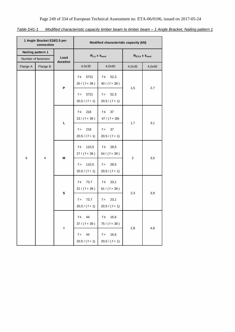
Page 249 of 334 of European Technical Assessment no. ETA-06/0106, issued on 2017-05-24
Table D41-1 Modified characteristic capacity timber beam to timber beam – 1 Angle Bracket, Nailing pattern 1
Flange A Flange B 4,0x35 4,0x60
f ≤ 5721 f ≤ 52,3
f > 5721 f > 52,3
f ≤ 218 f ≤ 37
f > 218 f > 37
f ≤ 110,5 f ≤ 28,5
f > 110,5 f > 28,5
f ≤ 73,7 f ≤ 23,1
f > 73,7 f > 23,1
f ≤ 44 f ≤ 16,6
f > 44 f > 16,6
31 / ( f + 39 ) 61 / ( f + 39 )
20,5 / ( f + 1) 20,5 / ( f + 1)
2,7
40 / ( f + 39 )
20,5 / ( f + 1)
20,5 / ( f + 1)
4,8
37 / ( f + 39 ) 75 / ( f + 39 )
20,5 / ( f + 1) 20,5 / ( f + 1)
3,1
3,5
27 / ( f + 39 ) 54 / ( f + 39 )
3,9
M
S
2,8
4,0x60
1,7
2
20,5 / ( f + 1)
Load
duration
2,3
4,0x35
1,5
23 / ( f + 39 ) 47 / ( f + 39)
20,5 / ( f + 1) 20,5 / ( f + 1)
R2/3,k x kmod
20 / ( f + 39 )
Modified characteristic capacity (kN)1 Angle Bracket E18/2.5 per
connection
Nailing pattern 1
Number of fasteners
6 4
R1,k x kmod
I
20,5 / ( f + 1)
P
L

Page 250 of 334 of European Technical Assessment no. ETA-06/0106, issued on 2017-05-24
Table D41-2 Modified characteristic capacity timber beam to timber beam – 1 Angle Bracket, Nailing pattern 2
Flange A Flange B 4,0x35 4,0x60
f ≤ 5721 f ≤ 52,3
f > 5721 f > 52,3
f ≤ 218 f ≤ 37
f > 218 f > 37
f ≤ 110,5 f ≤ 28,5
f > 110,5 f > 28,5
f ≤ 73,7 f ≤ 23,1
f > 73,7 f > 23,1
f ≤ 44 f ≤ 16,6
f > 44 f > 16,6
1 Angle Bracket E18/2.5 per
connectionModified characteristic capacity (kN)
Nailing pattern 2
Load
duration
R1,k x kmod R2/3,k x kmod
Number of fasteners
4,0x35 4,0x60
15 4
P 2,4 4,3
20 / ( f + 39 ) 40 / ( f + 39 )
20,5 / ( f + 1) 20,5 / ( f + 1)
L 2,8 5
23 / ( f + 39 ) 47 / ( f + 39)
20,5 / ( f + 1) 20,5 / ( f + 1)
M 3,2 5,8
37 / ( f + 39 ) 54 / ( f + 39 )
20,5 / ( f + 1) 20,5 / ( f + 1)
S 3,7 6,5
31 / ( f + 39 ) 61 / ( f + 39 )
20,5 / ( f + 1) 20,5 / ( f + 1)
I 4,5 8,0
37 / ( f + 39 ) 75 / ( f + 39 )
20,5 / ( f + 1) 20,5 / ( f + 1)

Page 251 of 334 of European Technical Assessment no. ETA-06/0106, issued on 2017-05-24
Table D41-3 Modified characteristic capacity timber beam to timber beam – 2 Angle Brackets, Nailing pattern 1
P 2,1 2,4 3,8 4,2 2,5 2,7 4,1 4,5
L 2,9 3,4 5,3 5,8 3,5 3,8 5,7 6,2
M 3,3 3,8 6,0 6,6 4,0 4,3 6,6 7,1
S 3,7 4,3 6,8 7,5 4,5 4,9 7,4 8,0
I 4,5 5,3 8,3 9,1 5,5 5,9 9,0 9,8
2 Angle Brackets E18/2.5 per
connectionModified characteristic capacities (kN)
Nailing pattern 1
Load
duration
R1,k x kmod R2/3,k x kmodNumber of Fasteners
Flange A Flange B CNA4,0x35 CNA4,0x60
6 4
CNA4,0x40 CNA4,0x50 CNA4,0x60 CNA4,0x35 CNA4,0x40 CNA4,0x50
Table D41-4 Modified characteristic capacity timber beam to timber beam – 2 Angle Brackets, Nailing pattern 2
P 2,5 2,8 3,4 3,7 4,1 4,5 5,5 5,8
L 3,4 3,9 4,7 5,2 5,7 6,2 7,6 8,1
M 3,9 4,5 5,4 5,9 6,6 7,1 8,7 9,3
S 4,4 5,0 6,0 6,7 7,4 8,0 9,8 10,4
I 5,4 6,2 7,4 8,1 9,0 9,8 12,0 12,8
Flange B CNA4,0x35 CNA4,0x60 CNA4,0x35 CNA4,0x60CNA4,0x40 CNA4,0x50 CNA4,0x40 CNA4,0x50
15 4
2 Angle Brackets E18/2.5 per
connectionModified characteristic capacities (kN)
Nailing pattern 2
Load
duration
R1,k x kmod R2/3,k x kmodNumber of Fasteners
Flange A

Page 252 of 334 of European Technical Assessment no. ETA-06/0106, issued on 2017-05-24
Table D41-5 Modified characteristic capacity timber column to timber beam – 1 Angle Bracket, Nailing pattern 3
Flange A Flange B 4,0x35 4,0x60
f ≤ 235,5 f ≤ 37,9
f > 235,5 f > 37,9
f ≤ 106,5 f ≤ 28
f > 106,5 f > 28
f ≤ 68,5 f ≤ 22,1
f > 68,5 f > 22,1
f ≤ 50,3 f ≤ 18,2
f > 50,3 f > 18,2
f ≤ 32,6 f ≤ 13,3
f > 32,6 f > 13,3
1 Angle Bracket E18/2.5 per
connectionModified characteristic capacity (kN)
Nailing pattern 3
Load
duration
R1,k x kmod R2/3,k x kmod
Number of fasteners
4,0x35 4,0x60
12 4
P 2,0 3,6
20 / ( f + 39 ) 40 / ( f + 39 )
17 / ( f + 1) 17 / ( f + 1)
L 2,4 4,1
23 / ( f + 39 ) 47 / ( f + 39)
17 / ( f + 1) 17 / ( f + 1)
M 2,8 4,7
27 / ( f + 39 ) 54 / ( f + 39 )
17 / ( f + 1) 17 / ( f + 1)
S 3,1 5,4
31 / ( f + 39 ) 61 / ( f + 39 )
17 / ( f + 1) 17 / ( f + 1)
I 3,8 6,5
37 / ( f + 39 ) 75 / ( f + 39 )
17 / ( f + 1) 17 / ( f + 1)
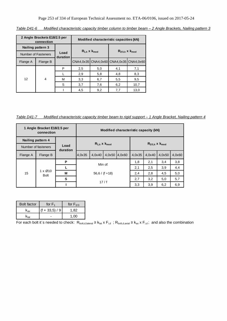
Page 253 of 334 of European Technical Assessment no. ETA-06/0106, issued on 2017-05-24
Table D41-6 Modified characteristic capacity timber column to timber beam – 2 Angle Brackets, Nailing pattern 3
P 2,5 5,0 4,1 7,1
L 2,9 5,8 4,8 8,3
M 3,3 6,7 5,5 9,5
S 3,7 7,6 6,2 10,7
I 4,5 9,2 7,7 13,0
CNA4,0x35 CNA4,0x60 CNA4,0x35 CNA4,0x60
Number of Fasteners
Nailing pattern 3R1,k x kmod R2/3,k x kmod
12 4
2 Angle Brackets E18/2.5 per
connectionModified characteristic capacities (kN)
Load
duration
Flange A Flange B
Table D41-7 Modified characteristic capacity timber beam to rigid support – 1 Angle Bracket, Nailing pattern 4
Flange A Flange B 4,0x35 4,0x40 4,0x50 4,0x60 4,0x35 4,0x40 4,0x50 4,0x60
P 1,8 2,1 3,4 3,8
L 2,1 2,5 3,9 4,4
M 2,4 2,8 4,5 5,0
S 2,7 3,2 5,0 5,7
I 3,3 3,9 6,2 6,9
R1,k x kmod
Modified characteristic capacity (kN)
Nailing pattern 4
Number of fastenersR2/3,k x kmod
Min of:
56,6 / (f +18)
17 / f
Load
duration
1 x Ø10
Bolt15
1 Angle Bracket E18/2.5 per
connection
Bolt factor for F1 for F2/3
kax (f + 33,5) / 9 1,82
klat - 1,00
For each bolt it´s needed to check: Rbolt,d,lateral ≥ klat x Fi,d ; Rbolt,d,axial ≥ kax x Fi,d ; and also the combination

Page 254 of 334 of European Technical Assessment no. ETA-06/0106, issued on 2017-05-24
Table D41-8 Modified characteristic capacity timber beam to rigid support – 2 Angle Brackets, Nailing pattern 4
Flange A Flange B 4,0x35 4,0x40 4,0x50 4,0x60 4,0x35 4,0x40 4,0x50 4,0x60
P 12,3 12,3 12,3 12,3 4,9 5,6 7,0 7,9
L 14,4 14,4 14,4 14,4 5,7 6,5 8,1 9,2
M 16,4 16,4 16,4 16,4 6,5 7,4 9,3 10,5
S 18,5 18,5 18,5 18,5 7,3 8,4 10,4 11,8
I 22,6 22,6 22,6 22,6 8,9 10,2 12,8 14,4
Number of fasteners
151 x Ø10
Bolt
2 Angle Brackets E18/2.5 per
connectionModified characteristic capacity (kN)
Nailing pattern 4
Load
duration
R1,k x kmod R2/3,k x kmod
Bolt factor for F1 for F2/3
kax 0,98 0,91
klat - 0,50
For each bolt it´s needed to check: Rbolt,d,lateral ≥ klat x Fi,d ; Rbolt,d,axial ≥ kax x Fi,d ; and also the combination
Table D41-9 Modified characteristic capacity timber column to rigid support – 1 Angle Bracket, Nailing pattern 5
Flange A Flange B 4,0x35 4,0x60 4,0x35 4,0x60
P 1,0 2,0
L 1,1 2,4
M 1,3 2,8
S 1,5 3,1
I 1,8 3,8
R1,k x kmod R2/3,k x kmod
Number of fasteners
121 x Ø10
Bolt
Min of:
56,5 / (f + 18)
17,7 / f
1 Angle Bracket E18/2.5 per
connection
Modified characteristic capacity
(kN)
Nailing pattern 5
Load
duration
Bolt factor for F1 for F2/3
kax (f + 33,5) / 9 1,82
klat - 1,00
For each bolt it´s needed to check: Rbolt,d,lateral ≥ klat x Fi,d ; Rbolt,d,axial ≥ kax x Fi,d ; and also the combination
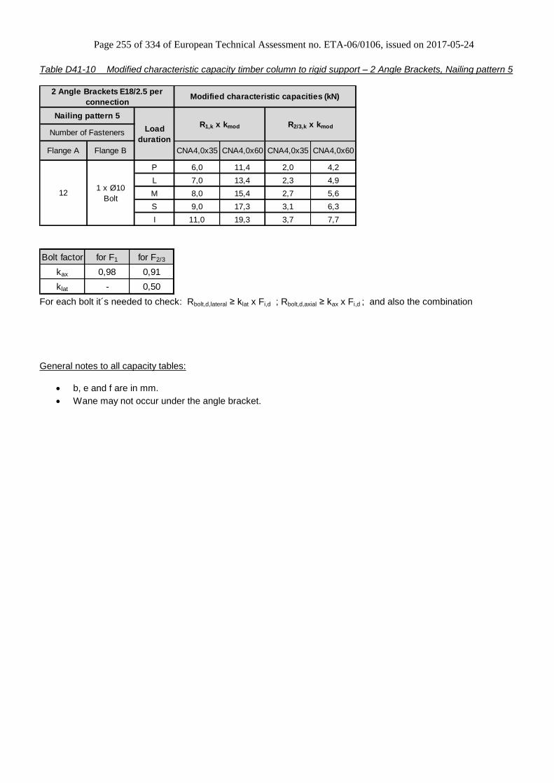
Page 255 of 334 of European Technical Assessment no. ETA-06/0106, issued on 2017-05-24
Table D41-10 Modified characteristic capacity timber column to rigid support – 2 Angle Brackets, Nailing pattern 5
P 6,0 11,4 2,0 4,2
L 7,0 13,4 2,3 4,9
M 8,0 15,4 2,7 5,6
S 9,0 17,3 3,1 6,3
I 11,0 19,3 3,7 7,7
Flange B CNA4,0x35 CNA4,0x60 CNA4,0x35 CNA4,0x60
121 x Ø10
Bolt
2 Angle Brackets E18/2.5 per
connectionModified characteristic capacities (kN)
Nailing pattern 5
Load
duration
R1,k x kmod R2/3,k x kmod
Number of Fasteners
Flange A
Bolt factor for F1 for F2/3
kax 0,98 0,91
klat - 0,50
For each bolt it´s needed to check: Rbolt,d,lateral ≥ klat x Fi,d ; Rbolt,d,axial ≥ kax x Fi,d ; and also the combination
General notes to all capacity tables:
b, e and f are in mm.
Wane may not occur under the angle bracket.
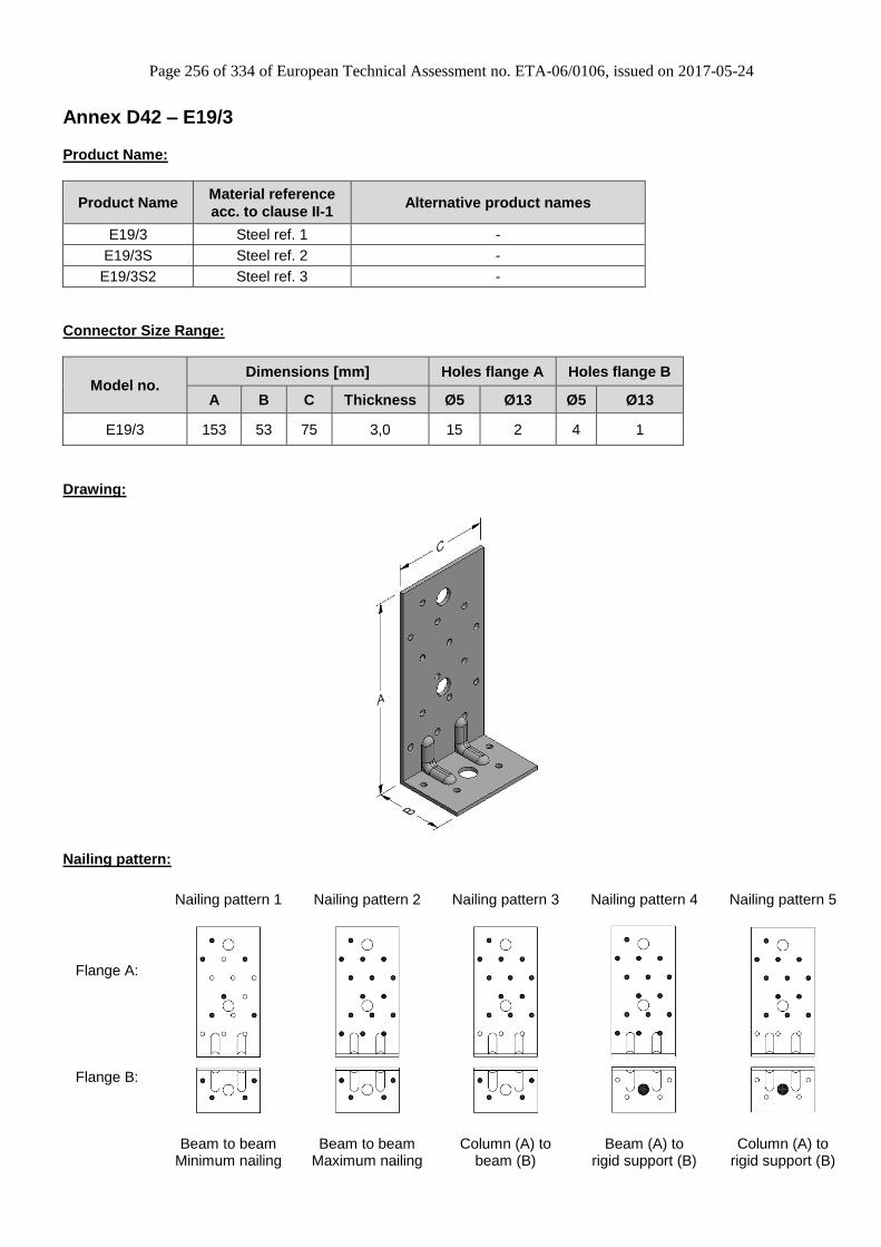
Page 256 of 334 of European Technical Assessment no. ETA-06/0106, issued on 2017-05-24
Annex D42 – E19/3
Product Name:
Product Name Material reference
acc. to clause II-1 Alternative product names
E19/3 Steel ref. 1 -
E19/3S Steel ref. 2 -
E19/3S2 Steel ref. 3 -
Connector Size Range:
Model no. Dimensions [mm] Holes flange A Holes flange B
A B C Thickness Ø5 Ø13 Ø5 Ø13
E19/3 153 53 75 3,0 15 2 4 1
Drawing:
Nailing pattern:
Nailing pattern 1 Nailing pattern 2 Nailing pattern 3 Nailing pattern 4 Nailing pattern 5
Flange A:
Flange B:
Beam to beam
Minimum nailing Beam to beam
Maximum nailing Column (A) to
beam (B) Beam (A) to
rigid support (B) Column (A) to
rigid support (B)

Page 257 of 334 of European Technical Assessment no. ETA-06/0106, issued on 2017-05-24
Table D42-1 Modified characteristic capacity timber beam to timber beam – 1 Angle Bracket, Nailing pattern 1
Flange A Flange B 4,0x35 4,0x60
f ≤ 200,6
f > 200,6
f ≤ 97,5
f > 97,5
f ≤ 64,1
f > 64,1
f ≤ 47,5
f > 47,5
f ≤ 31,1
f > 31,1
1 Angle Bracket E19/3 per
connection
Nailing pattern 1
Number of fasteners
6 4
R1,k x kmod
I
P
L
M
1,5
47 / ( f + 40)
34,6 / ( f + 2 )
R2/3,k x kmod
Modified characteristic capacity (kN)
S
2,8
4,0x60
1,7
2,0
34,6 / ( f + 2 )
Load
duration
2,3
4,0x35
27 / ( f + 40)
75 / ( f + 40 )
34,6 / ( f + 2 )
3,0
3,5
54 / ( f + 40 )
3,931 / ( f + 40)
37 / ( f + 40)
61 / ( f + 40 )
34,6 / ( f + 2 )
2,6
40 / ( f + 40 )
34,6 / ( f + 2 )
20 / ( f + 40)
23 / ( f + 40)
4,8

Page 258 of 334 of European Technical Assessment no. ETA-06/0106, issued on 2017-05-24
Table D42-2 Modified characteristic capacity timber beam to timber beam – 1 Angle Bracket, Nailing pattern 2
Flange A Flange B 4,0x35 4,0x60
f ≤ 200,6
f > 200,6
f ≤ 97,5
f > 97,5
f ≤ 64,1
f > 64,1
f ≤ 47,5
f > 47,5
f ≤ 31,1
f > 31,1
1 Angle Bracket E19/3 per
connectionModified characteristic capacity (kN)
Nailing pattern 2
Load
duration
R1,k x kmod R2/3,k x kmod
Number of fasteners
4,0x35 4,0x60
15 4
P 20 / ( f + 40) 2,4 4,3
40 / ( f + 40 )
34,6 / ( f + 2 )
L 23 / ( f + 40) 2,8 5,0
47 / ( f + 40)
34,6 / ( f + 2 )
M 27 / ( f + 40) 3,2 5,7
54 / ( f + 40 )
34,6 / ( f + 2 )
S 31 / ( f + 40) 3,6 6,4
61 / ( f + 40 )
34,6 / ( f + 2 )
I 37 / ( f + 40) 4,4 7,9
75 / ( f + 40 )
34,6 / ( f + 2 )

Page 259 of 334 of European Technical Assessment no. ETA-06/0106, issued on 2017-05-24
Table D42-3 Modified characteristic capacity timber beam to timber beam – 2 Angle Brackets, Nailing pattern 1
P 2,1 2,4 3,8 4,2 2,5 2,7 4,1 4,5
L 2,9 3,4 5,3 5,8 3,5 3,8 5,7 6,2
M 3,3 3,8 6,0 6,6 4,0 4,3 6,6 7,1
S 3,7 4,3 6,8 7,5 4,5 4,9 7,4 8,0
I 4,5 5,3 8,3 9,1 5,5 5,9 9,0 9,8
CNA4,0x60
6 4
CNA4,0x40 CNA4,0x50 CNA4,0x60 CNA4,0x35 CNA4,0x40 CNA4,0x50
2 Angle Brackets E19/3 per
connectionModified characteristic capacities (kN)
Nailing pattern 1
Load
duration
R1,k x kmod R2/3,k x kmodNumber of Fasteners
Flange A Flange B CNA4,0x35
Table D42-4 Modified characteristic capacity timber beam to timber beam – 2 Angle Brackets, Nailing pattern 2
P 2,5 2,8 3,4 3,7 4,1 4,4 5,4 5,8
L 3,4 3,9 4,7 5,2 5,7 6,2 7,5 8,1
M 3,9 4,5 5,4 5,9 6,5 7,0 8,6 9,2
S 4,4 5,0 6,0 6,7 7,3 7,9 9,6 10,4
I 5,4 6,2 7,4 8,1 8,9 9,7 11,8 12,7
15 4
2 Angle Brackets E19/3 per
connectionModified characteristic capacities (kN)
Nailing pattern 2
Load
duration
R1,k x kmod R2/3,k x kmodNumber of Fasteners
Flange A Flange B CNA4,0x35 CNA4,0x60 CNA4,0x35 CNA4,0x60CNA4,0x40 CNA4,0x50 CNA4,0x40 CNA4,0x50
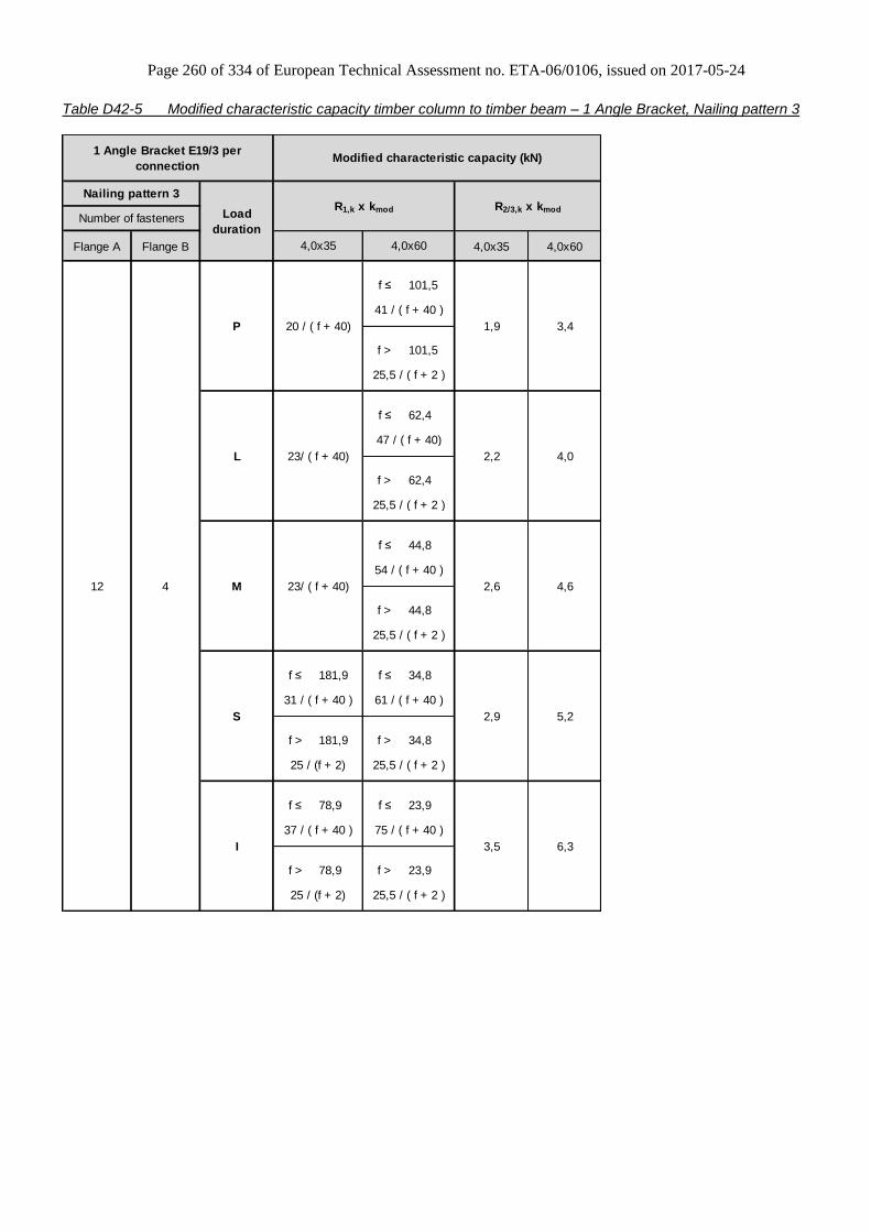
Page 260 of 334 of European Technical Assessment no. ETA-06/0106, issued on 2017-05-24
Table D42-5 Modified characteristic capacity timber column to timber beam – 1 Angle Bracket, Nailing pattern 3
Flange A Flange B 4,0x35 4,0x60
f ≤ 101,5
f > 101,5
f ≤ 62,4
f > 62,4
f ≤ 44,8
f > 44,8
f ≤ 181,9 f ≤ 34,8
f > 181,9 f > 34,8
f ≤ 78,9 f ≤ 23,9
f > 78,9 f > 23,9
3,5 6,3
37 / ( f + 40 ) 75 / ( f + 40 )
25 / (f + 2) 25,5 / ( f + 2 )
2,6 4,6
54 / ( f + 40 )
25,5 / ( f + 2 )
S 2,9 5,2
31 / ( f + 40 ) 61 / ( f + 40 )
25 / (f + 2)
1,9 3,4
41 / ( f + 40 )
25,5 / ( f + 2 )
L 2,2 4,0
47 / ( f + 40)
25,5 / ( f + 2 )
23/ ( f + 40)
4,0x60
12 4
P
M
25,5 / ( f + 2 )
I
20 / ( f + 40)
23/ ( f + 40)
1 Angle Bracket E19/3 per
connectionModified characteristic capacity (kN)
Nailing pattern 3
Load
duration
R1,k x kmod R2/3,k x kmod
Number of fasteners
4,0x35
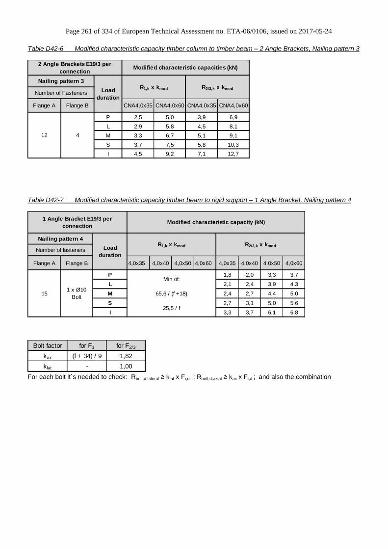
Page 261 of 334 of European Technical Assessment no. ETA-06/0106, issued on 2017-05-24
Table D42-6 Modified characteristic capacity timber column to timber beam – 2 Angle Brackets, Nailing pattern 3
P 2,5 5,0 3,9 6,9
L 2,9 5,8 4,5 8,1
M 3,3 6,7 5,1 9,1
S 3,7 7,5 5,8 10,3
I 4,5 9,2 7,1 12,7
2 Angle Brackets E19/3 per
connectionModified characteristic capacities (kN)
Load
duration
Flange A Flange B CNA4,0x35 CNA4,0x60 CNA4,0x35 CNA4,0x60
Number of Fasteners
Nailing pattern 3R1,k x kmod R2/3,k x kmod
12 4
Table D42-7 Modified characteristic capacity timber beam to rigid support – 1 Angle Bracket, Nailing pattern 4
Flange A Flange B 4,0x35 4,0x40 4,0x50 4,0x60 4,0x35 4,0x40 4,0x50 4,0x60
P 1,8 2,0 3,3 3,7
L 2,1 2,4 3,9 4,3
M 2,4 2,7 4,4 5,0
S 2,7 3,1 5,0 5,6
I 3,3 3,7 6,1 6,8
R2/3,k x kmod
Min of:
65,6 / (f +18)
25,5 / f
Load
duration
1 x Ø10
Bolt15
1 Angle Bracket E19/3 per
connection
R1,k x kmod
Modified characteristic capacity (kN)
Nailing pattern 4
Number of fasteners
Bolt factor for F1 for F2/3
kax (f + 34) / 9 1,82
klat - 1,00
For each bolt it´s needed to check: Rbolt,d,lateral ≥ klat x Fi,d ; Rbolt,d,axial ≥ kax x Fi,d ; and also the combination
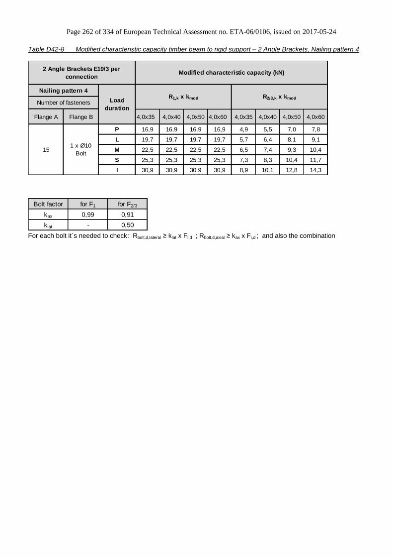
Page 262 of 334 of European Technical Assessment no. ETA-06/0106, issued on 2017-05-24
Table D42-8 Modified characteristic capacity timber beam to rigid support – 2 Angle Brackets, Nailing pattern 4
Flange A Flange B 4,0x35 4,0x40 4,0x50 4,0x60 4,0x35 4,0x40 4,0x50 4,0x60
P 16,9 16,9 16,9 16,9 4,9 5,5 7,0 7,8
L 19,7 19,7 19,7 19,7 5,7 6,4 8,1 9,1
M 22,5 22,5 22,5 22,5 6,5 7,4 9,3 10,4
S 25,3 25,3 25,3 25,3 7,3 8,3 10,4 11,7
I 30,9 30,9 30,9 30,9 8,9 10,1 12,8 14,3
Number of fasteners
151 x Ø10
Bolt
2 Angle Brackets E19/3 per
connectionModified characteristic capacity (kN)
Nailing pattern 4
Load
duration
R1,k x kmod R2/3,k x kmod
Bolt factor for F1 for F2/3
kax 0,99 0,91
klat - 0,50
For each bolt it´s needed to check: Rbolt,d,lateral ≥ klat x Fi,d ; Rbolt,d,axial ≥ kax x Fi,d ; and also the combination

Page 263 of 334 of European Technical Assessment no. ETA-06/0106, issued on 2017-05-24
Table D42-9 Modified characteristic capacity timber column to rigid support – 1 Angle Bracket, Nailing pattern 5
Flange A Flange B 4,0x35 4,0x60
L
Min of:
20,6 / f
65,6 / ( f + 18)
3,7
1 Angle Bracket E19/3 per
connectionModified characteristic capacity (kN)
Nailing pattern 5
Load
duration
R1,k x kmod R2/3,k x kmod
Number of fasteners
4,0x35 4,0x60
Min of:
23,6 / f
65,6 / ( f + 18)
2,3 4,3121 x Ø10
Bolt
P
Min of:
17,6 / f
65,6 / ( f + 18)
1,7
I
3,2
Min of:
25,5 / f
65,6 / ( f + 18)
3,2 5,9
Min of:
25,5 / f
65,6 / ( f + 18)
S
Min of:
25,5 / f
65,6 / ( f + 18)
2,6 4,8
2,0
M
Bolt factor for F1 for F2/3
kax (f + 34) / 9 1,82
klat - 1,00
For each bolt it´s needed to check: Rbolt,d,lateral ≥ klat x Fi,d ; Rbolt,d,axial ≥ kax x Fi,d ; and also the combination

Page 264 of 334 of European Technical Assessment no. ETA-06/0106, issued on 2017-05-24
Table D42-10 Modified characteristic capacity timber column to rigid support – 2 Angle Brackets, Nailing pattern 5
P 6,0 11,5 3,5 6,4
L 7,0 13,4 4,1 7,5
M 8,0 15,4 4,7 8,6
S 9,0 17,3 5,3 9,7
I 11,0 19,1 6,5 11,8
R2/3,k x kmod
Number of Fasteners
Flange A Flange B CNA4,0x35 CNA4,0x60 CNA4,0x35 CNA4,0x60
121 x Ø10
Bolt
2 Angle Brackets E19/3 per
connectionModified characteristic capacities (kN)
Nailing pattern 5
Load
duration
R1,k x kmod
Bolt factor for F1 for F2/3
kax 0,99 0,91
klat - 0,50
For each bolt it´s needed to check: Rbolt,d,lateral ≥ klat x Fi,d ; Rbolt,d,axial ≥ kax x Fi,d ; and also the combination
General notes to all capacity tables:
b, e and f are in mm.
Wane may not occur under the angle bracket.

Page 265 of 334 of European Technical Assessment no. ETA-06/0106, issued on 2017-05-24
Annex D43 – ADR6090
Product Name:
Product
Name
Material reference
acc. to clause II-1 Alternative product names
ADR6090 Steel ref. 1 -
ADR6090S Steel ref. 2 -
ADR6090S2 Steel ref. 3 -
Connector Size Range:
Model no. Dimensions [mm] Holes flange A Holes flange B
A B C Thickness Ø5 Ø5 Ø12
ADR6090 90 60 60 2,5 5 5 1
Drawing:
Nailing pattern:
Nailing pattern 1 Nailing pattern 2
Flange A:
Flange B:
Beam to beam Beam to rigid

Page 266 of 334 of European Technical Assessment no. ETA-06/0106, issued on 2017-05-24
Table D43-1 Modified characteristic capacity timber beam to timber beam – 2 Angle Brackets
4,0x40 4,0x60
1,8 2,7
2,0 3,0
2,3 3,2
2,6 3,4
2,9 3,8
2 Angle Brackets ADR6090 per
connection
Modified characteristic capacity
per connection (kN)
Nailing
pattern
Nailing
pattern 1
Flange BFlange A
Number of fasteners
3 3
L
M
S
I
R1,k x kmod
CNA Connector nail
Load
duration
P
Table D43-2 Modified characteristic capacity timber beam to timber beam – 1 Angle Bracket
4,0x40 4,0x60
23 / ( f + 28 ) 23 / ( f + 28 )
max max
20 / ( f + 50 ) 32 / ( f + 50 )
23 / ( f + 28 ) 23 / ( f + 28 )
max max
22 / ( f + 50 ) 37 / ( f + 50 )
23 / ( f + 28 )
max 23 / ( f + 28 )
26 / ( f + 50 )
23 / ( f + 28 )
max 23 / ( f + 28 )
29 / ( f + 50 )
23 / ( f + 28 )
max 23 / ( f + 28 )
35 / ( f + 50 )
1 Angle Bracket ADR6090 per
connection
Modified characteristic capacity
per connection (kN)
Nailing
pattern
Nailing
pattern 1
Number of fasteners
Flange A Flange B
3 3
L
M
S
I
R1,k x kmod
CNA Connector nail
Load
duration
P
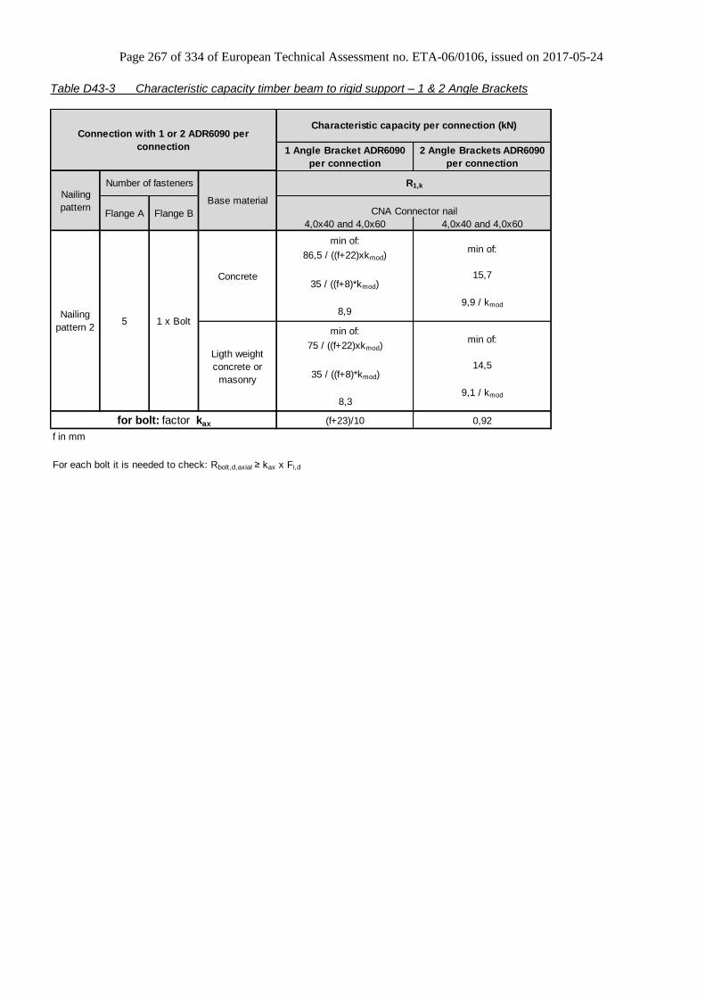
Page 267 of 334 of European Technical Assessment no. ETA-06/0106, issued on 2017-05-24
Table D43-3 Characteristic capacity timber beam to rigid support – 1 & 2 Angle Brackets
1 Angle Bracket ADR6090
per connection
2 Angle Brackets ADR6090
per connection
4,0x40 and 4,0x60 4,0x40 and 4,0x60
Concrete
min of:
86,5 / ((f+22)xkmod)
35 / ((f+8)*kmod)
8,9
min of:
15,7
9,9 / kmod
Ligth weight
concrete or
masonry
min of:
75 / ((f+22)xkmod)
35 / ((f+8)*kmod)
8,3
min of:
14,5
9,1 / kmod
(f+23)/10 0,92
f in mm
For each bolt it is needed to check: Rbolt,d,axial ≥ kax x Fi,d
Characteristic capacity per connection (kN)
CNA Connector nail
Nailing
pattern 2
for bolt: factor kax
R1,k
5 1 x Bolt
Connection with 1 or 2 ADR6090 per
connection
Nailing
pattern
Number of fasteners
Flange A Flange B
Base material
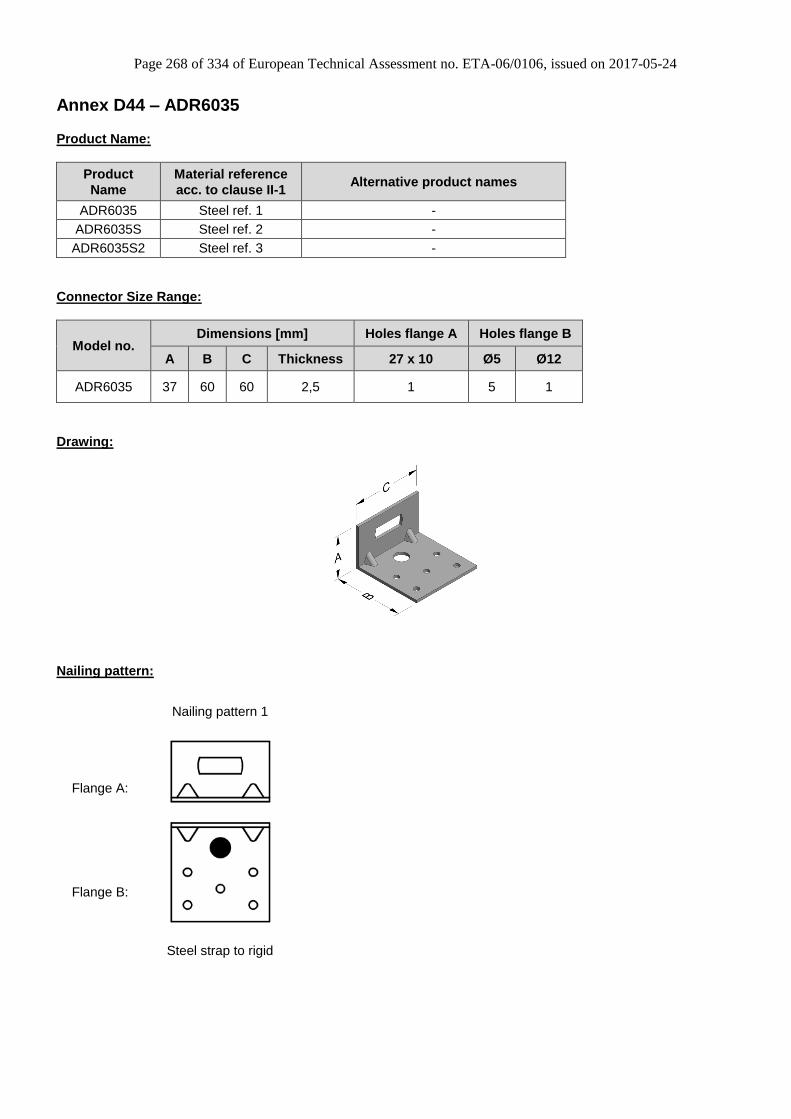
Page 268 of 334 of European Technical Assessment no. ETA-06/0106, issued on 2017-05-24
Annex D44 – ADR6035
Product Name:
Product
Name
Material reference
acc. to clause II-1 Alternative product names
ADR6035 Steel ref. 1 -
ADR6035S Steel ref. 2 -
ADR6035S2 Steel ref. 3 -
Connector Size Range:
Model no. Dimensions [mm] Holes flange A Holes flange B
A B C Thickness 27 x 10 Ø5 Ø12
ADR6035 37 60 60 2,5 1 5 1
Drawing:
Nailing pattern:
Nailing pattern 1
Flange A:
Flange B:
Steel strap to rigid

Page 269 of 334 of European Technical Assessment no. ETA-06/0106, issued on 2017-05-24
Table D44-1 Characteristic capacity steel strap to rigid – 1 Angle Bracket
Characteristic capacity per
connection (kN)
R1,k
Flange A Flange B 1 x M10 bolt
Concrete 5,2 / kmod
Ligth weight concrete or
masonry4,0 / kmod
2,2
For each bolt it is needed to check: Rbolt,d,axial ≥ kax x Fi,d
Nailing
pattern 1
for bolt: factor kax
1 Angle Bracket ADR6035
per connection
Base materialNailing
pattern
Number of fasteners
- 1 x M10 Bolt
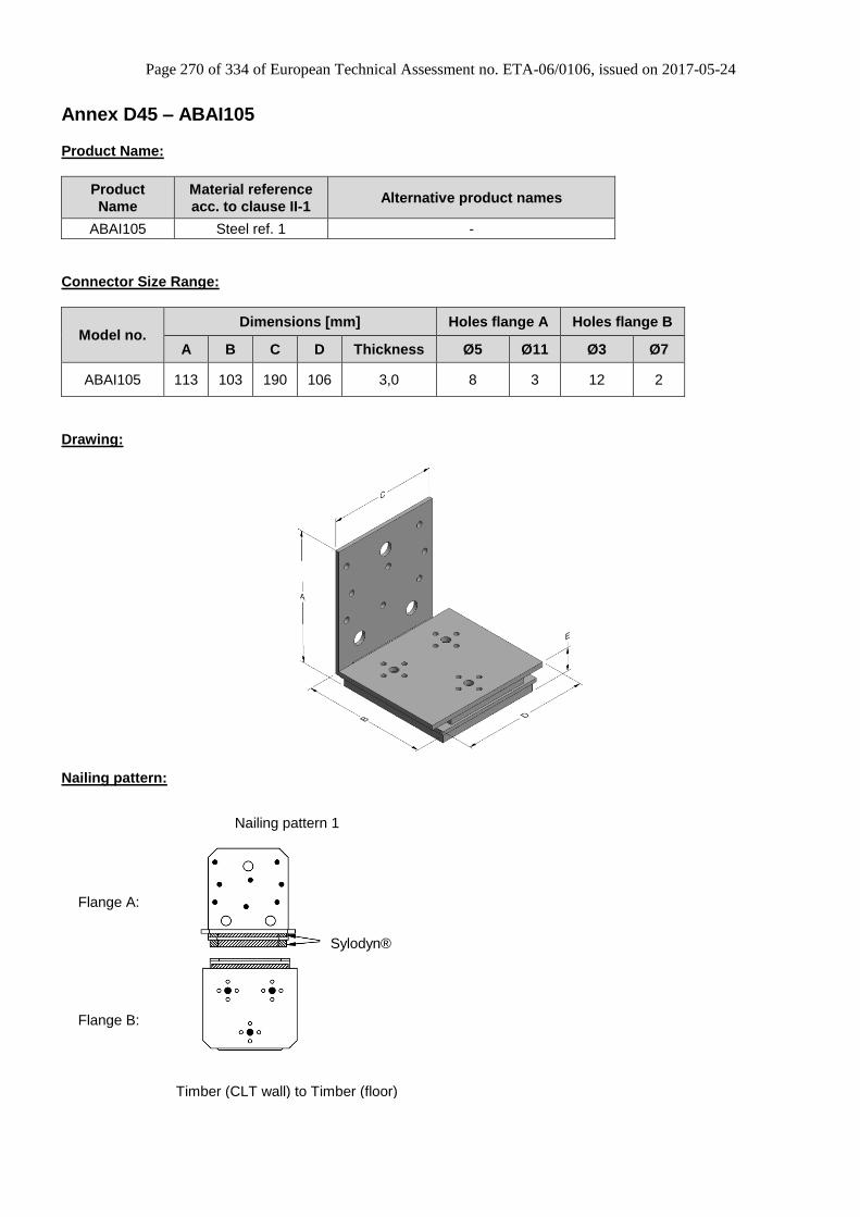
Page 270 of 334 of European Technical Assessment no. ETA-06/0106, issued on 2017-05-24
Annex D45 – ABAI105
Product Name:
Product
Name
Material reference
acc. to clause II-1 Alternative product names
ABAI105 Steel ref. 1 -
Connector Size Range:
Model no. Dimensions [mm] Holes flange A Holes flange B
A B C D Thickness Ø5 Ø11 Ø3 Ø7
ABAI105 113 103 190 106 3,0 8 3 12 2
Drawing:
Nailing pattern:
Nailing pattern 1
Flange A:
Flange B:
Timber (CLT wall) to Timber (floor)
Sylodyn®

Page 271 of 334 of European Technical Assessment no. ETA-06/0106, issued on 2017-05-24
Table D45-1 Modified characteristic capacity CLT wall to floor – 1 Angle Bracket
Flange A (Wall) Flange B (Floor)
Characteristic
value
Rk (kN)
1,4 1,4 3,3 1,6
Slip modulus
kser (kN/mm)0,8 0,68 1,16 0,8
Characteristic capacity per connection (kN)
Nailing
pattern 1
1 Angle Bracket ABAI105
per connection
Nailing
pattern
Number of fasteners
8 x CNA4,0x60
or CSA5,0x503 x SDS25600
R1,k R2/3,k R4,k R5,k
Table D45-2 Ultimate limit state capacity CLT wall to floor – 1 Angle Bracket
Flange A (Wall) Flange B (Floor)
Nailing
pattern 1
8 x CNA4,0x60
or CSA5,0x503 x SDS25600 7,9 5,9 7,3 5,4
Ultimate limit state values shall only be used under rare disaster situations, e.g. disproportionate callapes, vehicle impact, etc…
To evaluate the connected displacements, the slip modulus from table D45-1 can be used.
R1,u R2/3,u
Ultimate limit state capacity per connection (kN)1 Angle Bracket ABAI105
per connection
Nailing
pattern
Number of fasteners
R4,u R5,u

Page 272 of 334 of European Technical Assessment no. ETA-06/0106, issued on 2017-05-24
Annex D46 – AG922
Product Name:
Product
Name
Material reference
acc. to clause II-1 Alternative product names
AG922 Steel ref. 1 -
AG922S Steel ref. 2 -
AG922S2 Steel ref. 3 -
Connector Size Range:
Model no. Dimensions [mm] Holes flange A Holes flange B
A B C Thickness Ø5 Ø13 Ø5 Ø13
AG922 121 79 150 2,5 26 26 18 13
Drawing:
Nailing pattern:
Nailing pattern 1 Nailing pattern 2 Nailing pattern 3 Nailing pattern 4
Flange A:
Flange B:
Beam to beam Column to beam Beam (A) to
to rigid support (B) Column (A) to
to rigid support (B)
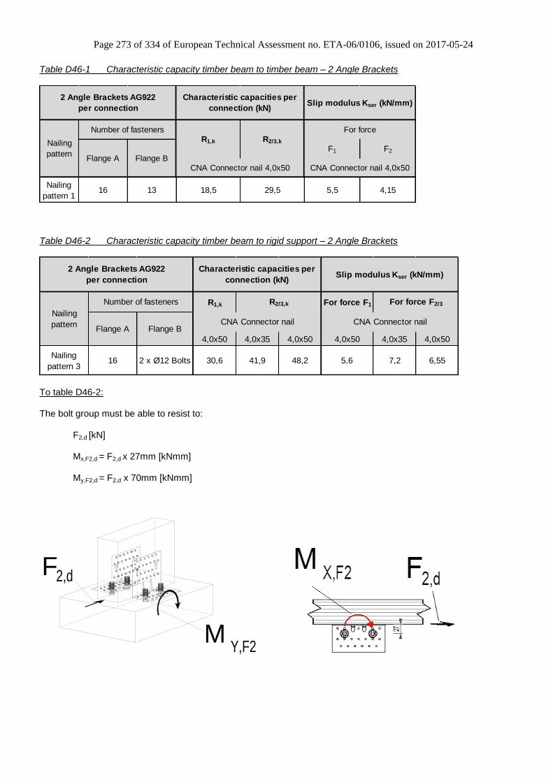
Page 273 of 334 of European Technical Assessment no. ETA-06/0106, issued on 2017-05-24
Table D46-1 Characteristic capacity timber beam to timber beam – 2 Angle Brackets
F1 F2
Nailing
pattern 116 13 18,5 29,5 5,5 4,15
Nailing
pattern
Number of fasteners
2 Angle Brackets AG922
per connection
Flange B
Characteristic capacities per
connection (kN)
R1,k R2/3,k
For force
Flange ACNA Connector nail 4,0x50 CNA Connector nail 4,0x50
Slip modulus Kser (kN/mm)
Table D46-2 Characteristic capacity timber beam to rigid support – 2 Angle Brackets
R1,k For force F1
4,0x50 4,0x35 4,0x50 4,0x50 4,0x35 4,0x50
Nailing
pattern 316 2 x Ø12 Bolts 30,6 41,9 48,2 5,6 7,2 6,55
Nailing
pattern
R2/3,k
Characteristic capacities per
connection (kN)
Flange A Flange BCNA Connector nail
Slip modulus Kser (kN/mm)
For force F2/3
CNA Connector nail
Number of fasteners
2 Angle Brackets AG922
per connection
To table D46-2:
The bolt group must be able to resist to:
F2,d [kN]
Mx,F2,d = F2,d x 27mm [kNmm]
My,F2,d = F2,d x 70mm [kNmm]
F 2,d
Y,F2M

Page 274 of 334 of European Technical Assessment no. ETA-06/0106, issued on 2017-05-24
Table D46-3 Characteristic capacity timber column to timber beam – 2 Angle Brackets
Characteristic capacities
per connection (kN)
Slip modulus Kser
(kN/mm)
For force
F1
CNA Connector nail 4,0x50 CNA Connector nail 4,0x50
Nailing
pattern 212 13 19,5 3,18
2 Angle Brackets AG922
per connection
Nailing
pattern
Number of fastenersR1,k
Flange A Flange B
Table D46-4 Characteristic capacity timber column to rigid support – 2 Angle Brackets
Characteristic capacities
per connection (kN)
Slip modulus Kser
(kN/mm)
For force
F1
CNA Connector nail 4,0x50 CNA Connector nail 4,0x50
Nailing
pattern 412 2 x Ø12 Bolts 37,5 10,59
2 Angle Brackets AG922
per connection
Nailing
pattern
Number of fastenersR1,k
Flange A Flange B
Table D46-5 Characteristic capacity timber beam to timber column – 1 Angle Bracket
Characteristic capacities
per connection (kN)
Slip modulus Kser
(kN/mm)
For force
F1
CNA Connector nail 4,0x50 CNA Connector nail 4,0x50
Nailing
pattern 212 13 22,6 3,67
1 Angle Bracket AG922
per connection
Nailing
pattern
Number of fastenersR1,k
Flange A Flange B
F2F1
12 Nails Ø4.0x50 in Flange A
13 Nails Ø4.0x50 in Flange B
Column

Page 275 of 334 of European Technical Assessment no. ETA-06/0106, issued on 2017-05-24
Table D46-6 Characteristic capacity timber beam to rigid support – 1 Angle Bracket
Characteristic capacities
per connection (kN)Slip modulus Kser (kN/mm)
For force
F1
CNA Connector nail 4,0x50 CNA Connector nail 4,0x50
Nailing
pattern 412 2 x Ø12 Bolts 24,8 3,71
R1,k
Flange A Flange B
2 Angle Brackets AG922
per connection
Nailing
pattern
Number of fasteners
Table D46-7 Bolt factors for D46-2, D46-4 & D46-6
AG922Connection with 1 Angle
Bracket (to table D46-6)
factor for: F1 F2/3 F1
kax 0,75 - 1,00
klat - see description 1,00
For each bolt-pair it's needed to check: Rbolt,d,lateral ≥ klat x Fi,d ; Rbolt,d,axial ≥ kax x Fi,d; and also the combination.
Connection with 2 Angle Brackets
(to table D46-2 & D46-4)
12 Nails CNA4.0x50 in Flange A
2 Anchors Ø12 in Flange B
Rigid support
F1

Page 276 of 334 of European Technical Assessment no. ETA-06/0106, issued on 2017-05-24
Annex D47 – ABR10525
Product Name:
Product
Name
Material reference
acc. to clause II-1 Alternative product names
ABR10525 Steel ref. 1 -
ABR10525S Steel ref. 2 -
ABR10525S2 Steel ref. 3 -
Connector Size Range:
Model no. Dimensions [mm] Holes flange A Holes flange B
A B C Thickness Ø5 Ø11 Ø14 Ø5 Ø14
ABR10525 105 105 90 2,5 10 2 1 14 1
Drawing:
Nailing pattern:
Nailing pattern 1 Nailing pattern 2 Nailing pattern 3 Nailing pattern 4
Flange A:
Flange B:
Beam to beam
Maximum nailing Beam to beam
Minimum nailing Beam (A)
to column (B) Beam (A)
to steel (B) 6 mm S355
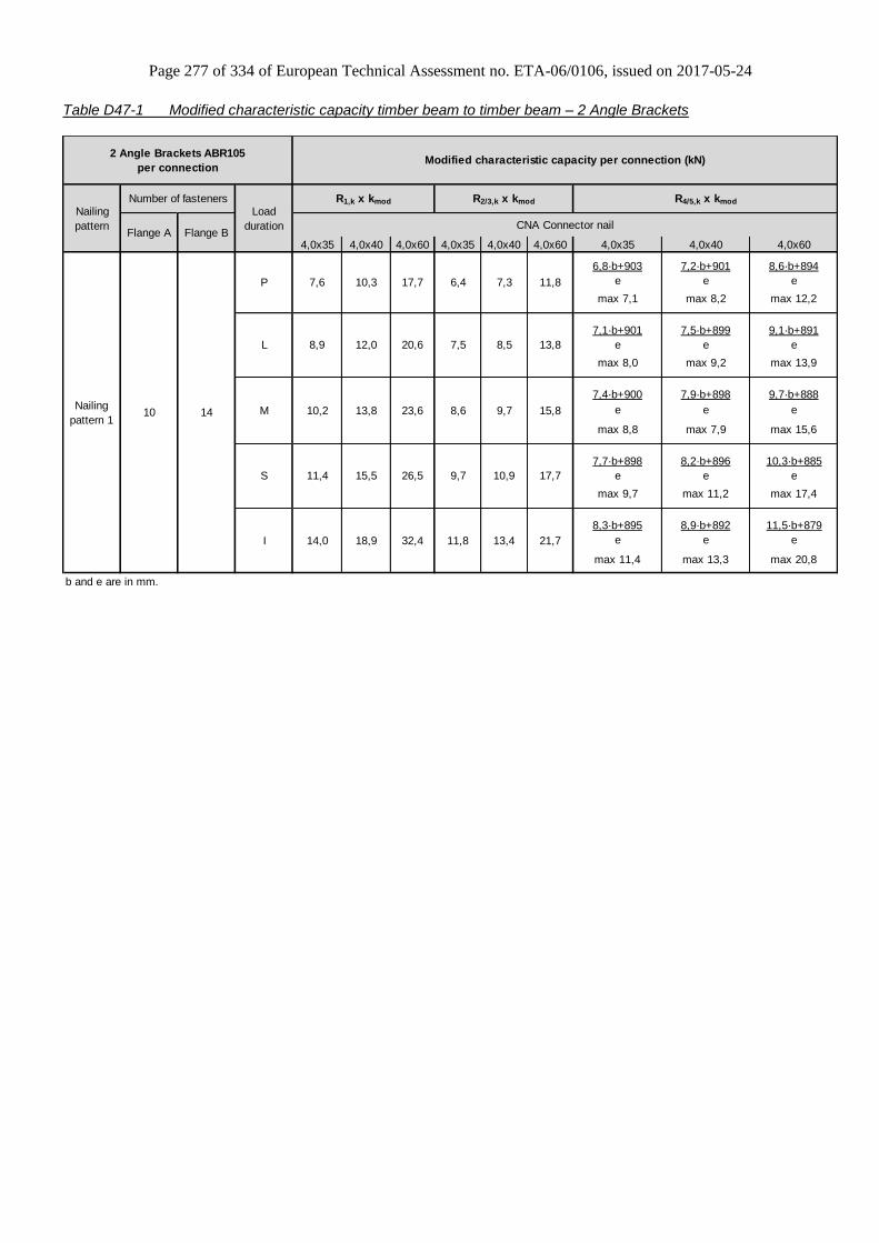
Page 277 of 334 of European Technical Assessment no. ETA-06/0106, issued on 2017-05-24
Table D47-1 Modified characteristic capacity timber beam to timber beam – 2 Angle Brackets
4,0x35 4,0x40 4,0x60 4,0x35 4,0x40 4,0x60 4,0x35 4,0x40 4,0x60
6,8·b+903 7,2·b+901 8,6·b+894
e e e
max 7,1 max 8,2 max 12,2
7,1·b+901 7,5·b+899 9,1·b+891
e e e
max 8,0 max 9,2 max 13,9
7,4·b+900 7,9·b+898 9,7·b+888
e e e
max 8,8 max 7,9 max 15,6
7,7·b+898 8,2·b+896 10,3·b+885
e e e
max 9,7 max 11,2 max 17,4
8,3·b+895 8,9·b+892 11,5·b+879
e e e
max 11,4 max 13,3 max 20,8
b and e are in mm.
10 14
Load
duration
R1,k x kmod R2/3,k x kmod R4/5,k x kmod
CNA Connector nail
Number of fasteners
Flange A Flange B
Modified characteristic capacity per connection (kN)
Nailing
pattern 1
P
L
M
S
I
6,4 11,8
Nailing
pattern
7,6 17,710,3 7,3
7,5 13,88,9 20,612,0 8,5
26,515,5 10,9
8,6 15,810,2 23,613,8 9,7
2 Angle Brackets ABR105
per connection
11,8 21,714,0 32,418,9 13,4
9,7 17,711,4

Page 278 of 334 of European Technical Assessment no. ETA-06/0106, issued on 2017-05-24
Table D47-2 Modified characteristic capacity timber beam to timber beam – 1 Angle Bracket
Table D47-2.1
4,0x35 4,0x40 4,0x60 4,0x35 4,0x40 4,0x60
f≤ 25: f≤ 27: f≤ 33:
221 249 358
f+75 f+75 f+75
f>25: f>27: f>33:
55 66 110
f f f
f≤ 27: f≤ 29: f≤ 35:
244 276 404
f+75 f+75 f+75
f>27: f>29: f>35:
64 77 129
f f f
f≤ 29: f≤ 31: f≤ 36:
267 303 450
f+75 f+75 f+75
f>29: f>31: f>36:
74 88 147
f f f
f≤ 30: f≤ 32: f≤ 35:
290 331 496
f+75 f+75 f+75
f>30: f>32: f>35:
83 99 159
f f f
f≤ 32: f≤ 34: f≤ 28:
336 386 587
f+75 f+75 f+75
f>32: f>34: f>28:
101 121 159
f f f
f, e and b are in mm.
8 10
Modified characteristic capacity per connection (kN)
CNA Connector nail
6,7
6,9
3,6
4,3
10,8
M
R1,k x kmod R2/3,k x kmod
3,2
1 Angle Bracket ABR10525
per connection
5,9
Number of fasteners
4,9 7,9
4,8 5,5 8,9
P
L
S
Load
duration
I 5,9
3,8
Nailing
pattern
4,3Nailing
pattern 1
Flange A Flange B
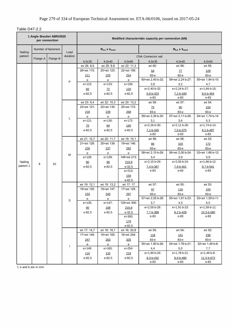
Page 279 of 334 of European Technical Assessment no. ETA-06/0106, issued on 2017-05-24
Table D47-2.2
4,0x35 4,0x40 4,0x60 4,0x35 4,0x40 4,0x60
e≤ 26: 8,0 e≤ 25: 8,8 e≤ 22: 11,3 e≤ 60: e≤ 58: e≤ 55:
26<e≤ 115: 25<e≤ 123: 22<e≤ 156: 64 77 129
211 220 254 83-e 83-e 83-e
e e e 60<e≤ 2,40·b-32: 58<e≤ 2,24·b-27: 55<e≤ 1,84·b-15:
e>115: e>123: e>156: 2,8 3,2 4,7
60 72 120 e>2,40·b-32: e>2,24·b-27: e>1,84·b-15:
e-82,5 e-82,5 e-82,5 6,8·b-323 7,2·b-349 8,6·b-454
e-83 e-83 e-83
e≤ 23: 9,4 e≤ 22: 10,3 e≤ 20: 13,2 e≤ 59: e≤ 57: e≤ 54:
23<e≤ 121: 22<e≤ 130: 20<e≤ 172: 75 90 150
218 228 268 83-e 83-e 83-e
e e e 59<e≤ 2,26·b-30: 57<e≤ 2,11·b-26: 54<e≤ 1,74·b-14:
e>121: e>130: e>172: 3,1 3,6 5,3
70 84 140 e>2,26·b-30: e>2,11·b-26: e>1,74·b-14:
e-82,5 e-82,5 e-82,5 7,1·b-345 7,5·b-375 9,1·b-497
e-83 e-83 e-83
e≤ 21: 10,7 e≤ 20: 11,7 e≤ 19: 15,1 e≤ 58: e≤ 56: e≤ 53:
21<e≤ 128: 20<e≤ 139: 19<e≤ 146: 86 103 172
226 237 282 83-e 83-e 83-e
e e e 58<e≤ 2,15·b-29: 56<e≤ 2,00·b-24: 53<e≤ 1,66·b-12:
e>128: e>139: 146<e≤ 213: 3,4 3,9 5,9
80 96 219,8 e>2,15·b-29: e>2,00·b-24: e>1,66·b-12:
e-82,5 e-82,5 e-32,5 7,4·b-367 7,9·b-401 9,7·b-541
e>213: e-83 e-83 e-83
159
e-82,5
e≤ 19: 12,1 e≤ 19: 13,2 e≤ 17: 17 e≤ 57: e≤ 55: e≤ 53:
19<e≤ 135: 19<e≤ 147: 17<e≤ 125: 97 116 193
233 245 297 83-e 83-e 83-e
e e e 57<e≤ 2,05·b-28: 55<e≤ 1,91·b-23: 53<e≤ 1,59·b-11:
e>135: e>147: 125<e≤ 300: 3,7 4,3 6,5
90 108 219,8 e>2,05·b-28: e>1,91·b-23: e>1,59·b-11:
e-82,5 e-82,5 e-32,5 7,7·b-388 8,2·b-428 10,3·b-585
e>300: e-83 e-83 e-83
179
e-82,5
e≤ 17: 14,7 e≤ 16: 16,1 e≤ 16: 20,8 e≤ 55: e≤ 54: e≤ 52:
17<e≤ 149: 16<e≤ 165: 16<e≤ 254: 118 141 236
247 263 325 83-e 83-e 83-e
e e e 55<e≤ 1,90·b-26: 54<e≤ 1,78·b-21: 52<e≤ 1,49·b-8:
e>149: e>165: e>254: 4,4 5,0 7,7
110 132 219 e>1,90·b-26: e>1,78·b-21: e>1,49·b-8:
e-82,5 e-82,5 e-82,5 8,3·b-432 8,9·b-480 11,5·b-672
e-83 e-83 e-83
f, e and b are in mm.
8 10
Modified characteristic capacity per connection (kN)
CNA Connector nail
M
R4,k x kmod R5,k x kmod
1 Angle Bracket ABR10525
per connection
Number of fasteners
P
L
S
Load
duration
I
Nailing
pattern
Nailing
pattern 1
Flange A Flange B
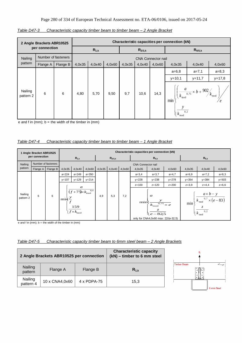
Page 280 of 334 of European Technical Assessment no. ETA-06/0106, issued on 2017-05-24
Table D47-3 Characteristic capacity timber beam to timber beam – 2 Angle Bracket
Flange A Flange B 4,0x35 4,0x40 4,0x60 4,0x35 4,0x40 4,0x60 4,0x35 4,0x40 4,0x60
a=6,8 a=7,1 a=8,3
y=10,1 y=11,7 y=17,8
e and f in (mm); b = the width of the timber in (mm)
Nailing
pattern 26 6
Characteristic capacities per connection (kN)
4,80 5,70 9,50 9,7 10,6 14,3
R4/5,k
CNA Connector nail
R1,k R2/3,k
2 Angle Brackets ABR10525
per connection
Nailing
pattern
Number of fasteners
2,0
mod
mod75,0
mod
902
min
k
y
e
kb
k
a
Table D47-4 Characteristic capacity timber beam to timber beam – 1 Angle Bracket
Flange A Flange B 4,0x35 4,0x40 4,0x60 4,0x35 4,0x40 4,0x60 4,0x35 4,0x40 4,0x60 4,0x35 4,0x40 4,0x60
a=224 a=249 a=350 a=3,4 a=3,7 a=4,7 a=6,9 a=7,2 a=8,3
y=107 y=129 y=214 y=228 y=238 y=278 y=354 y=384 y=503
z=100 z=120 z=200 z=3,9 z=4,4 z=6,6
e and f in (mm); b = the width of the timber in (mm)
4,9 5,3 7,2
R5,k
Characteristic capacities per connection (kN)
R4,kR1,k R2/3,k
CNA Connector nail
only for CNA4,0x60 max: 22/(e-32,5)
1 Angle Bracket ABR10525
per connection
Nailing
pattern
Number of fasteners
Nailing
pattern 26 6
mod
4,0
mod
159
75
min
kf
f
y
kf
a
5,82
min75,0
mod
e
z
ek
y
a
2,0
mod
7,0
mod 83min
k
z
ek
yba
Table D47-5 Characteristic capacity timber beam to 6mm steel beam – 2 Angle Brackets
2 Angle Brackets ABR10525 per connection Characteristic capacity
(kN) – timber to 6 mm steel
Nailing pattern
Flange A Flange B R1,k
Nailing pattern 4
10 x CNA4,0x60 4 x PDPA-75 15,3
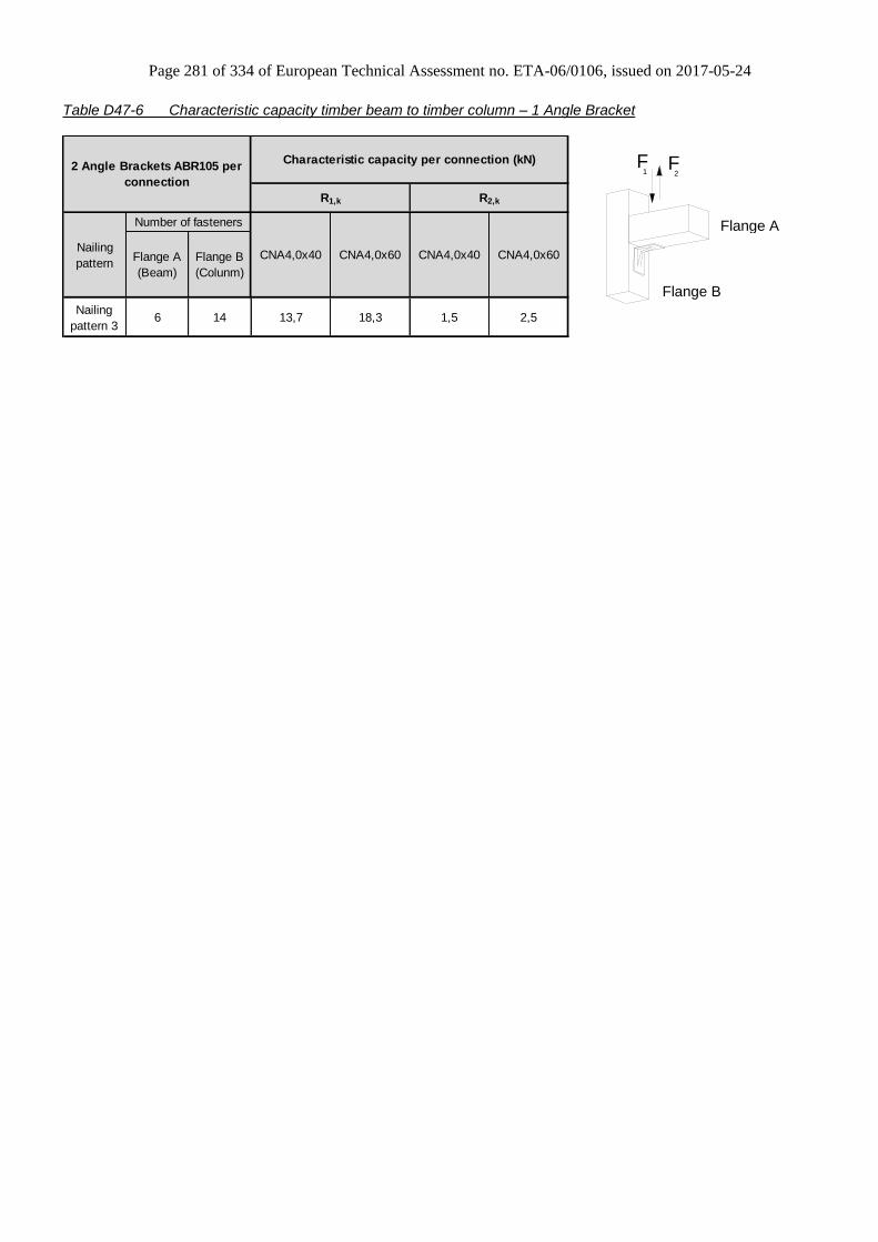
Page 281 of 334 of European Technical Assessment no. ETA-06/0106, issued on 2017-05-24
Table D47-6 Characteristic capacity timber beam to timber column – 1 Angle Bracket
Flange A
(Beam)
Flange B
(Colunm)
Nailing
pattern 36 14 13,7 18,3 1,5 2,5
Characteristic capacity per connection (kN)
R1,k R2,k
2 Angle Brackets ABR105 per
connection
Nailing
pattern
Number of fasteners
CNA4,0x40 CNA4,0x60 CNA4,0x40 CNA4,0x60
F1 2
F
Flange A
Flange B
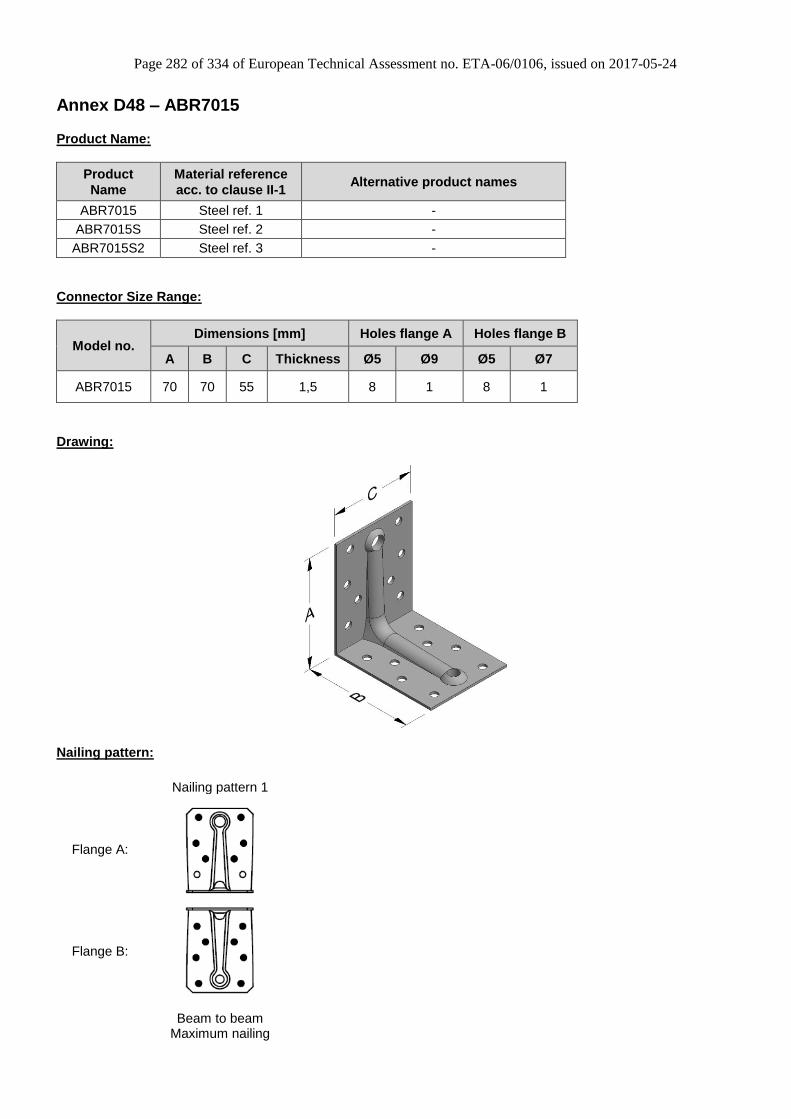
Page 282 of 334 of European Technical Assessment no. ETA-06/0106, issued on 2017-05-24
Annex D48 – ABR7015
Product Name:
Product
Name
Material reference
acc. to clause II-1 Alternative product names
ABR7015 Steel ref. 1 -
ABR7015S Steel ref. 2 -
ABR7015S2 Steel ref. 3 -
Connector Size Range:
Model no. Dimensions [mm] Holes flange A Holes flange B
A B C Thickness Ø5 Ø9 Ø5 Ø7
ABR7015 70 70 55 1,5 8 1 8 1
Drawing:
Nailing pattern:
Nailing pattern 1
Flange A:
Flange B:
Beam to beam
Maximum nailing
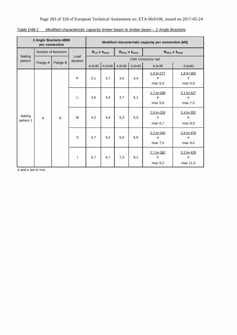
Page 283 of 334 of European Technical Assessment no. ETA-06/0106, issued on 2017-05-24
Table D48-1 Modified characteristic capacity timber beam to timber beam – 2 Angle Brackets
4,0x35 4,0x40 4,0x35 4,0x40 4,0x35 4,0x40
1,5·b+277 1,8·b+302
e e
max 5,0 max 6,0
1,7·b+298 2,1·b+327
e e
max 5,8 max 7,0
2,0·b+319 2,4·b+352
e e
max 6,7 max 8,0
2,2·b+340 2,6·b+378
e e
max 7,5 max 9,0
2,7·b+382 3,2·b+428
e e
max 9,2 max 11,0
b and e are in mm.
6 8
Nailing
pattern
Load
duration
R1,k x kmod R2/3,k x kmod R4/5,k x kmod
CNA Connector nail
Number of fasteners
Flange A Flange B
2 Angle Brackets AB90
per connectionModified characteristic capacity per connection (kN)
4,0 4,43,1 3,7
Nailing
pattern 1
P
L
M
S
I
5,3 5,94,2 4,9
4,7 5,5
4,7 5,13,6 4,3
7,3 8,15,7 6,7
6,0 6,6
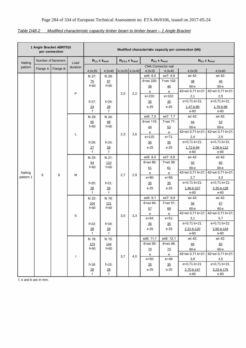
Page 284 of 334 of European Technical Assessment no. ETA-06/0106, issued on 2017-05-24
Table D48-2 Modified characteristic capacity timber beam to timber beam – 1 Angle Bracket
4,0x35 4,0x40 4,0x35 4,0x40 4,0x35 4,0x40 4,0x35 4,0x40
f≤ 27: f≤ 29: e≤6: 6,0 e≤7: 6,6 e≤ 42: e≤ 42:
75 87 6<e≤ 220: 7<e≤ 102: 38 45
f+60 f+60 38 46 60-e 60-e
e e 42<e≤ 0,71·b+21: 42<e≤ 0,71·b+21:
e>220: e>102: 2,1 2,5
f>27: f>29: 35 35 e>0,71·b+21: e>0,71·b+21:
24 28 e-25 e-25 1,47·b-80 1,76·b-96
f f e-60 e-60
f≤ 29: f≤ 24: e≤6: 7,0 e≤7: 7,7 e≤ 42: e≤ 42:
85 98 6<e≤ 115: 7<e≤ 71: 44 52
f+60 f+60 44 53 60-e 60-e
e e 42<e≤ 0,71·b+21: 42<e≤ 0,71·b+21:
e>115: e>71: 2,4 2,9
f>29: f>24: 35 35 e>0,71·b+21: e>0,71·b+21:
27 28 e-25 e-25 1,72·b-94 2,06·b-112
f f e-60 e-60
f≤ 25: f≤ 21: e≤6: 8,0 e≤7: 8,8 e≤ 42: e≤ 42:
94 110 6<e≤ 80: 7<e≤ 58: 50 60
f+60 f+60 51 61 60-e 60-e
e e 42<e≤ 0,71·b+21: 42<e≤ 0,71·b+21:
e>80: e>58: 2,7 3,3
f>25: f>21: 35 35 e>0,71·b+21: e>0,71·b+21:
28 28 e-25 e-25 1,96·b-107 2,35·b-128
f f e-60 e-60
f≤ 22: f≤ 18: e≤6: 9,1 e≤7: 9,9 e≤ 42: e≤ 42:
104 121 6<e≤ 64: 7<e≤ 51: 56 67
f+60 f+60 57 68 60-e 60-e
e e 42<e≤ 0,71·b+21: 42<e≤ 0,71·b+21:
e>64: e>51: 3,1 3,7
f>22: f>18: 35 35 e>0,71·b+21: e>0,71·b+21:
28 28 e-25 e-25 2,21·b-120 2,65·b-144
f f e-60 e-60
f≤ 18: f≤ 15: e≤6: 11,1 e≤6: 12,1 e≤ 42: e≤ 42:
123 144 6<e≤ 50: 6<e≤ 48: 69 82
f+60 f+60 70 73 60-e 60-e
e e 42<e≤ 0,71·b+21: 42<e≤ 0,71·b+21:
e>50: e>48: 3,8 4,5
f>18: f>15: 35 35 e>0,71·b+21: e>0,71·b+21:
28 28 e-25 e-25 2,70·b-147 3,23·b-176
f f e-60 e-60
f, e and b are in mm.
Modified characteristic capacity per connection (kN)1 Angle Bracket ABR7015
per connection
Nailing
pattern 1
S 3,0
M 2,7
Number of fasteners
Flange A Flange B
2,3
R1,k x kmod R2/3,k x kmodNailing
pattern
R4,k x kmod R5,k x kmodLoad
duration CNA Connector nail
6 8
I 3,7 4,0
2,0
L 2,6
3,3
2,9
2,2P

Page 285 of 334 of European Technical Assessment no. ETA-06/0106, issued on 2017-05-24
Annex D49 – ACR / ACRL
Product Name:
Product
Name
Material reference
acc. to clause II-1 Alternative product names
ACR7010 Steel ref. 1 -
ACR7012 Steel ref. 1 -
ACR7015 Steel ref. 1 -
ACR9012 Steel ref. 1 -
ACR9015 Steel ref. 1 -
ACR9020 Steel ref. 1 -
ACR10512 Steel ref. 1 -
ACR10515 Steel ref. 1 -
ACR10520 Steel ref. 1 -
ACRL10520 Steel ref. 1 -
ACR7010S Steel ref. 2 -
ACR7012S Steel ref. 2 -
ACR7015S Steel ref. 2 -
ACR9012S Steel ref. 2 -
ACR9015S Steel ref. 2 -
ACR9020S Steel ref. 2 -
ACR10512S Steel ref. 2 -
ACR10515S Steel ref. 2 -
ACR10520S Steel ref. 2 -
ACRL10520S Steel ref. 2 -
ACR7010S2 Steel ref. 3 -
ACR7012S2 Steel ref. 3 -
ACR7015S2 Steel ref. 3 -
ACR9012S2 Steel ref. 3 -
ACR9015S2 Steel ref. 3 -
ACR9020S2 Steel ref. 3 -
ACR10512S2 Steel ref. 3 -
ACR10515S2 Steel ref. 3 -
ACR10520S2 Steel ref. 3 -
ACRL10520S2 Steel ref. 3 -

Page 286 of 334 of European Technical Assessment no. ETA-06/0106, issued on 2017-05-24
Connector Size Range:
Model no. Dimensions [mm] Holes flange A Holes flange B
A B C Thickness Ø5 Ø8,5 Ø11 Ø11x31 Ø5 Ø8,5 Ø11 Ø11x31
ACR7010 70 70 55 1,0 6 1 - - 6 1 - -
ACR7012 70 70 55 1,25 6 1 - - 6 1 - -
ACR7015 70 70 55 1,5 6 1 - - 6 1 - -
ACR9012 88 88 65 1,25 10 - 1 - 5 - 1 -
ACR9015 88 88 65 1,5 10 - 1 - 5 - 1 -
ACR9020 88 88 65 2,0 10 - 1 - 5 - 1 -
ACR10512 105 105 90 1,25 10 - 3 - 14 - 1 -
ACR10515 105 105 90 1,5 10 - 3 - 14 - 1 -
ACR10520 105 105 90 2,0 10 - 3 - 14 - 1 -
ACRL10520 105 105 90 2,0 10 - 2 1 14 - - 1
Drawing:
ACR70 ACR90
ACR100 ACRL100

Page 287 of 334 of European Technical Assessment no. ETA-06/0106, issued on 2017-05-24
Nailing pattern:
Nailing pattern 1 Nailing pattern 2 Nailing pattern 3 Nailing pattern 4
Flange A:
Flange B:
ACR7010, ACR7012, ACR7015
Timber to Timber Maximum nailing
ACR9012, ACR9015, ACR9020
Timber to Timber Maximum nailing
ACR10512, ACR10515, ACRL10520
Timber to Timber Maximum nailing
ACR10520, ACRL10520
Timber to rigid
Nailing pattern 5 Nailing pattern 6 Nailing pattern 7
Flange A:
Flange B:
ACR10520, ACRL10520
Timber to rigid
ACR10520, ACRL10520
Timber to rigid
ACR10520, ACRL10520
Timber to rigid
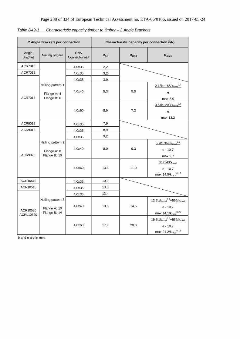
Page 288 of 334 of European Technical Assessment no. ETA-06/0106, issued on 2017-05-24
Table D49-1 Characteristic capacity timber to timber – 2 Angle Brackets
Angle
BracketNailing pattern
CNA
Connector nailR1,k R2/3,k R4/5,k
ACR7010 4,0x35 2,2
ACR7012 4,0x35 3,2
4,0x35 3,9
2,13b+165/kmod0,7
e
max 8,0
3,54b+200/kmod0,6
e
max 13,2
ACR9012 4,0x35 7,9
ACR9015 4,0x35 8,9
4,0x35 9,2
6,7b+369/kmod0,7
e - 10,7
max 9,7
8b+343/kmod
e - 10,7
max 14,5/kmod0,15
ACR10512 4,0x35 10,9
ACR10515 4,0x35 13,0
4,0x35 13,4
12,7b/kmod0,7+565/kmod
e - 10,7
max 14,1/kmod0,25
15,6b/kmod0,6+556/kmod
e - 10,7
max 21,2/kmod0,15
b and e are in mm.
Nailing pattern 2
Flange A: 8
Flange B: 10
Nailing pattern 3
Flange A: 10
Flange B: 14
4,0x60
ACR9020
ACR10520
ACRL10520
20,3
4,0x40 10,8 14,5
4,0x60 17,9
4,0x60 7,38,9
4,0x40 8,0 9,3
13,3 11,9
Characteristic capacity per connection (kN)2 Angle Brackets per connection
5,05,34,0x40
ACR7015
Nailing pattern 1
Flange A: 4
Flange B: 6

Page 289 of 334 of European Technical Assessment no. ETA-06/0106, issued on 2017-05-24
Table D49-2 Characteristic capacity timber to timber – 1 Angle Bracket
4,0
x40
4,0
x60
4,0
x40
4,0
x60
4,0x40 4,0x60
min of: min of:
2,5 4,2
30 49
55-e 55-e
2,7b+53 4,4b+89
e e
e= e= min of: min of:
1 4,7 1 5,8 8,5
20 4,3/kmod0,2 20 kmod
0,4 kmod0,25
50 1,8/kmod0,2 50 2,6/kmod
0,2 ; 2,2/kmod
75 1,2/kmod0,2 75 1,8/kmod
0,2 ; 1,5/kmod 77 129
100 0,8 100 1,1/kmod0,2 ; 1,0/kmod 68 - e 68 - e
125 0,5 125 0,8 ; 0,7/kmod 7,2/(kmod0,75·b-308/kmod
0,55) 8,8/(kmod0,6·b-408/kmod
0,45)
150 0,4 150 0,8 ; 0,6/kmod e - 68 e - 68
e= e= min of: min of:
1 7,2 1 8,1 11,2
20 7,2 20 kmod0,45 kmod
0,35
50 3,4/kmod0,35 50
75 2,3/kmod0,35 75 137 228
100 1,7/kmod0,35 100 2,3/kmod
0,3 ; 2,3/kmod 85 - e 85 - e
125 1,4/kmod0,35 125 1,9/kmod
0,3 ; 1,7/kmod 12,8/(kmod0,7·b-639/kmod
0,55) 15,7/(kmod0,6·b-840/kmod
0,45)
150 1,1/kmod0,35
150 1,4/kmod0,3 ; 1,4/kmod e - 85 e - 85
b and e are in mm.
min of:
CNA Connector nail
1 Angle Bracket
per connection
Angle
BracketNailing pattern
4,0x40
Characteristic capacity per connection (kN)
R1,k
3,7
(e-35)·kmod
3,3/kmod0,3
min of:
3,1
51
e·kmod
14
(e-35)·kmod
6,1
2,7 2,5
4,0x60
R4,k
ACR7015
Nailing pattern 1
Flange A: 4
Flange B: 6
min of:
ACR9020
10,27,395,4
Nailing pattern 3
Flange A: 10
Flange B: 14
ACR10520
ACRL10520
4,5
9,2
4,9/kmod0,35
Nailing pattern 2
Flange A: 8
Flange B: 10
4 4,7 6
R5,k
6,7
9,2
6,1
min of:
R2/3,k
2,4
51
e·kmod
14
The capacities have been found based on the assumption that the purlin is prevented from rotation.
2/3F
f1F
F1
F4
F with f=01
e

Page 290 of 334 of European Technical Assessment no. ETA-06/0106, issued on 2017-05-24
Table D49-3 Characteristic capacity timber beam to rigid support – 2 Angle Brackets
4.0x35 4.0x40 4.0x50 4.0x60 4.0x75 4.0x35 4.0x40 4.0x50 4.0x60 4.0x75
*In this case the test had shown that the limiting factor is the bolt resistance of connection ACRL to timber. The bolt resistance must be calculated using the Eurocode 5
§8.2.3 and consider only failure mode (j) and (k).
2 x Ø10 Bolts
10 1 x Ø10 Bolt
1 x Ø10 Bolt 2 x Ø10 Bolts
Nailing
pattern 4
Nailing
pattern 5
Nailing
pattern 6 & 7
10
R1,k R2,k
1 Angle Bracket ACR10520 or ACRL10520 per
connection
Nailing
pattern
Number of fasteners
Flange A Flange B
16,0
10,1 11,7 15,0 15,0 15,0 6,0
24,1 27,6 28,5 28,5 28,5 10,8
CNA Connector nail
Characteristic capacity per connection (kN)
7,0 9,0 10,5 11,7
7,5* - - - - -
11,7 14,2 15,1

Page 291 of 334 of European Technical Assessment no. ETA-06/0106, issued on 2017-05-24
Annex D50 – MAXIMUS
Product Name:
Product
Name
Material reference
acc. to clause II-1 Alternative product names
MAXIMUS Steel ref. 1 -
MAXIMUSS Steel ref. 2 -
MAXIMUSS2 Steel ref. 3 -
Connector Size Range:
Model no. Dimensions [mm]
Small
holes
Large
holes
A B C D Thickness Ø5 Ø21
MAXIMUS 494 623 100 C 240 15 + C + 15 2,5 10 2
Drawing:
Nailing pattern:
Nailing pattern 1 Nailing pattern 2
4 x CSA5,0x50 on each side CSA5,0x50 on the bottom
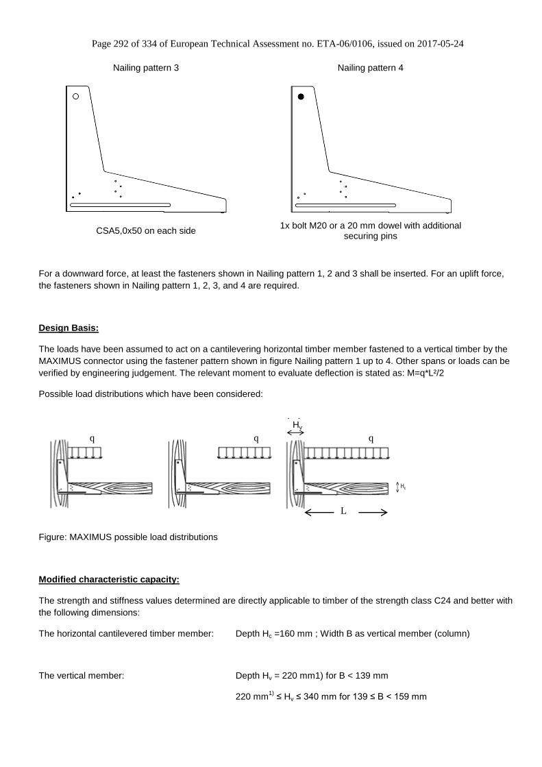
Page 292 of 334 of European Technical Assessment no. ETA-06/0106, issued on 2017-05-24
Nailing pattern 3 Nailing pattern 4
CSA5,0x50 on each side 1x bolt M20 or a 20 mm dowel with additional
securing pins
For a downward force, at least the fasteners shown in Nailing pattern 1, 2 and 3 shall be inserted. For an uplift force,
the fasteners shown in Nailing pattern 1, 2, 3, and 4 are required.
Design Basis:
The loads have been assumed to act on a cantilevering horizontal timber member fastened to a vertical timber by the
MAXIMUS connector using the fastener pattern shown in figure Nailing pattern 1 up to 4. Other spans or loads can be
verified by engineering judgement. The relevant moment to evaluate deflection is stated as: M=q*L²/2
Possible load distributions which have been considered:
Figure: MAXIMUS possible load distributions
Modified characteristic capacity:
The strength and stiffness values determined are directly applicable to timber of the strength class C24 and better with
the following dimensions:
The horizontal cantilevered timber member: Depth Hc =160 mm ; Width B as vertical member (column)
The vertical member: Depth Hv = 220 mm1) for B < 139 mm
220 mm1)
≤ Hv ≤ 340 mm for 139 ≤ B < 159 mm
Hv
Hc
L
q q q

Page 293 of 334 of European Technical Assessment no. ETA-06/0106, issued on 2017-05-24
220 mm1)
≤ Hv < 700 mm for B ≥ 159 mm
1): These values may be reduced to 180 mm if only downward forces can occur.
Higher depths Hv can be tolerated if a splitting reinforcement designed for at least Fk = 8,8 kN is applied near the
dowel. If the width B is smaller than 120 mm the characteristic load-carrying capacity can be determined by applying a
factor B/120 mm to the capacities listed in table D50-1.
The characteristic load-carrying capacity qR,k for a cantilever with a length L = 1200 mm is listed in the table D50-1
below. The common types of distributed loads have been evaluated also considering the possible positions of
distributed loads shown in the figure D50-3.
Table D50-1 Characteristic capacity timber beam to column – 1 MAXIMUS
P 43
L 43
M 48
S 67
I 85
*)Cφ shall be reduced to 60% of these values if the timber moisture exceeds 18% for longer term
Spring stiffness* Cφ of
the connection for a
downward force (kNm)
Load duration
downward
7,02 -2,60
uplift
Characteristic distributed load capacity
qR,k per connector (kN/m) and a lever
arm L=1200mm
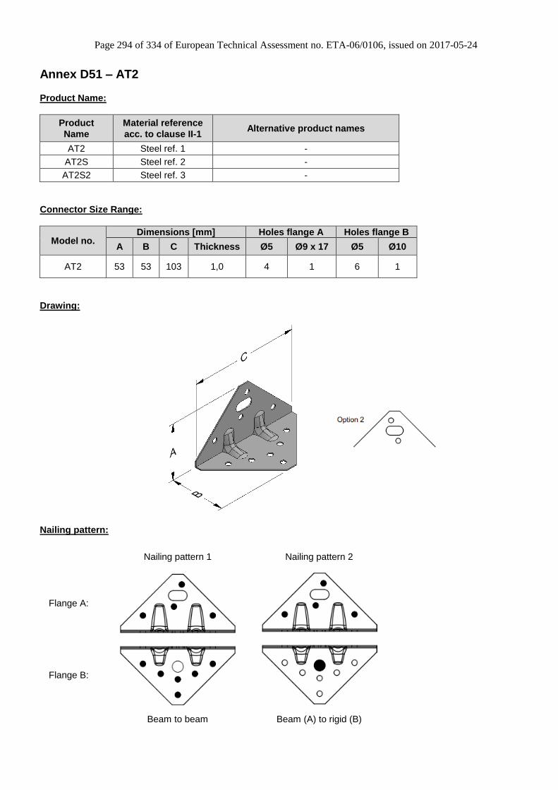
Page 294 of 334 of European Technical Assessment no. ETA-06/0106, issued on 2017-05-24
Annex D51 – AT2
Product Name:
Product
Name
Material reference
acc. to clause II-1 Alternative product names
AT2 Steel ref. 1 -
AT2S Steel ref. 2 -
AT2S2 Steel ref. 3 -
Connector Size Range:
Model no. Dimensions [mm] Holes flange A Holes flange B
A B C Thickness Ø5 Ø9 x 17 Ø5 Ø10
AT2 53 53 103 1,0 4 1 6 1
Drawing:
Nailing pattern:
Nailing pattern 1 Nailing pattern 2
Flange A:
Flange B:
Beam to beam Beam (A) to rigid (B)

Page 295 of 334 of European Technical Assessment no. ETA-06/0106, issued on 2017-05-24
Table D51-1 Characteristic capacity timber beam to timber beam – 2 Angle Brackets
R1,k R2/3,k
4,0x35 4,0x35
Nailing
pattern 14 6 5,3 11,1
Characteristic capacity per connection (kN)
CNA Connector nail
2 Angle Brackets AT2 per
connection
Nailing
pattern
Number of nails
Flange A Flange B
Table D51-2 Characteristic capacity timber beam to rigid – 2 Angle Brackets
R1,k R2/3,k
4,0x35 4,0x35
Nailing
pattern 24 1 x Ø8 Bolt 4,5 8,0
Characteristic capacity per connection (kN)
CNA Connector nail
2 Angle Brackets AT2 per
connection
Nailing
pattern
Number of nails
Flange A Flange B
factor for: F1 F2/3 F4/5,bolt 1 F4/5,bolt 2
kax 0,62 0,35 - -
klat - 0,50 - -
For each bolt it's needed to check: Rbolt,d,lateral ≥ klat x Fi,d ; Rbolt,d,axial ≥ kax x Fi,d; and also the combination.
2 Angle Brackets AT2 per connection

Page 296 of 334 of European Technical Assessment no. ETA-06/0106, issued on 2017-05-24
Annex D52 – ABR865
Product Name:
Product
Name
Material reference
acc. to clause II-1 Alternative product names
ABR865 Steel ref. 1 -
ABR865S Steel ref. 2 -
ABR865S2 Steel ref. 3 -
Connector Size Range:
Model no. Dimensions [mm] Holes flange A Holes flange B
A B C Thickness Ø9 Ø9
ABR865 65 80 145 3,0 3 3
Drawing:
Nailing pattern:
Nailing pattern 1
Flange A:
Flange B:
Timber to Timber
(The optional holes are only for constructive using.)
F2
1F
max
. ~ 1
0
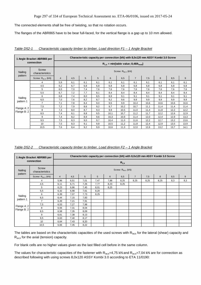
Page 297 of 334 of European Technical Assessment no. ETA-06/0106, issued on 2017-05-24
The connected elements shall be free of twisting, so that no rotation occurs.
The flanges of the ABR865 have to be bear full-faced, for the vertical flange is a gap up to 10 mm allowed.
Table D52-1 Characteristic capacity timber to timber, Load direction F1 – 1 Angle Bracket
Screw
characteristics
Screw: Rax,k (kN) 4 4,5 5 5 6 6,5 7 7,5 8 8,5 9
4 5,9 6,1 6,1 6,1 6,1 6,1 6,1 6,1 6,1 6,1 6,1
4,5 6,2 6,7 6,8 6,8 6,8 6,8 6,8 6,8 6,8 6,8 6,8
5 6,5 7,0 7,4 7,6 7,6 7,6 7,6 7,6 7,6 7,6 7,6
5,5 6,7 7,2 7,7 8,1 8,4 8,4 8,4 8,4 8,4 8,4 8,4
6 6,8 7,4 8,0 8,5 8,9 9,1 9,1 9,1 9,1 9,1 9,1
6,5 7,0 7,6 8,2 8,7 9,2 9,6 9,9 9,9 9,9 9,9 9,9
7 7,1 7,8 8,4 9,0 9,5 9,9 10,4 10,6 10,6 10,6 10,6
7,5 7,2 7,9 8,6 9,2 9,7 10,2 10,7 11,1 11,4 11,4 11,4
8 7,3 8,0 8,7 9,3 9,9 10,5 11,0 11,4 11,8 12,2 12,2
8,5 7,4 8,1 8,8 9,5 10,1 10,7 11,2 11,7 12,2 12,6 12,9
9 7,4 8,2 8,9 9,6 10,3 10,9 11,4 12,0 12,4 12,9 13,3
9,5 7,5 8,3 9,0 9,7 10,4 11,0 11,6 12,2 12,7 13,2 13,6
10 7,5 8,3 9,1 9,8 10,5 11,2 11,8 12,4 12,9 13,5 13,9
10,5 7,6 8,4 9,2 9,9 10,6 11,3 12,0 12,6 13,2 13,7 14,1
Nailing
pattern 1
Flange A: 2
Flange B: 2
Nailing
pattern
Screw: Rlat,k (kN)
Characteristic capacity per connection (kN) with 8,0x120 mm ASSY Kombi 3.0 Screw
R1,k = min[table value; 8,48/kmod]
1 Angle Bracket ABR865 per
connection
Table D52-2 Characteristic capacity timber to timber, Load direction F2 – 1 Angle Bracket
R2,k
Screw
characteristics
Screw: Rax,k (kN) 4 4,5 5 5 6 6,5 7 7,5 8 8,5 9
4 5,96 6,51 7,01 7,47 7,88 8,25 8,25 8,25 8,25 8,3 8,3
4,5 6,11 6,71 7,26 7,77 8,23 8,25
5 6,23 6,86 7,45 8,01 8,25
5,5 6,32 6,98 7,61 8,20
6 6,39 7,07 7,73 8,25
6,5 6,44 7,15 7,83
7 6,49 7,21 7,91
7,5 6,53 7,27 7,98
8 6,56 7,31 8,04
8,5 6,58 7,35 8,09
9 6,61 7,38 8,13
9,5 6,63 7,40 8,17
10 6,64 7,43 8,20
10,5 6,66 7,45 8,22
Nailing
pattern 1
Flange A: 2
Flange B: 2
Screw: Rlat,k (kN)
Characteristic capacity per connection (kN) with 8,0x120 mm ASSY Kombi 3.0 Screw
Nailing
pattern
1 Angle Bracket ABR865 per
connection
The tables are based on the characteristic capacities of the used screws with Rlat,k for the lateral (shear) capacity and
Rax,k for the axial (tension) capacity.
For blank cells are no higher values given as the last filled cell before in the same column.
The values for characteristic capacities of the fastener with Rlat,k=4,75 kN and Rax,k=7,04 kN are for connection as
described following with using screws 8,0x120 ASSY Kombi 3.0 according to ETA 11/0190:
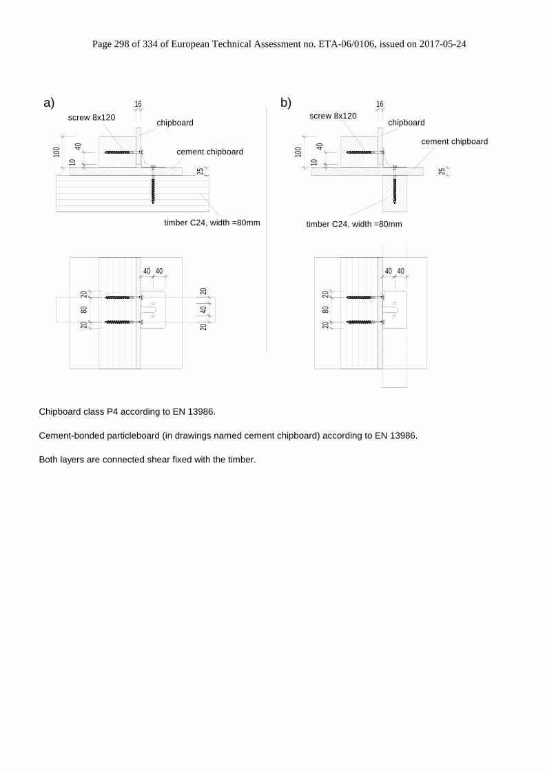
Page 298 of 334 of European Technical Assessment no. ETA-06/0106, issued on 2017-05-24
16
25
100
1040
2040
20
4040
2080
20
16
25
100
1040
4040
2080
20
cement chipboard
chipboard
timber C24, width =80mm
screw 8x120
cement chipboard
chipboardscrew 8x120
timber C24, width =80mm
a) b)
Chipboard class P4 according to EN 13986.
Cement-bonded particleboard (in drawings named cement chipboard) according to EN 13986.
Both layers are connected shear fixed with the timber.

Page 299 of 334 of European Technical Assessment no. ETA-06/0106, issued on 2017-05-24
Annex D53 – ACFET200 & ACFET200PP
Product Name:
Product Name Material reference
acc. to clause II-1 Alternative product names
ACFET200 Steel ref. 1 -
ACFET200PP Steel ref. 1 -
ACFET200S Steel ref. 2 -
ACFET200PPS Steel ref. 2 -
ACFET200S2 Steel ref. 3 -
ACFET200PPS2 Steel ref. 3 -
Connector Size Range:
Model no. Dimensions [mm] Holes flange A Holes flange B
A B C Thickness Ø12 Ø5
ACFET200 49 100 200 4,0 1 5
ACFET200PP 78 102 200 4,0 1 5
Drawing:
ACFET200 ACFET200PP
Table D53-1 Characteristic capacity timber to rigid – 1 Angle Bracket
1 Angle Bracket ACFET200
or
ACFET200PP
Nailing
1 M10 Concrete Screw/Bolt Gk = 185 KNmm / (e-5 mm) uinit = G x (e-5 mm)2 / 2400
The concrete screw/bolt is subjected to a shear force of Fv,k = Gk and a tension force of Fax,k = Gk * e / 30
Characteristic capacity
per connection (kN)Vertical displacement (mm)
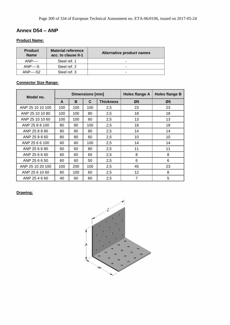
Page 300 of 334 of European Technical Assessment no. ETA-06/0106, issued on 2017-05-24
Annex D54 – ANP
Product Name:
Product
Name
Material reference
acc. to clause II-1 Alternative product names
ANP---- Steel ref. 1 -
ANP----S Steel ref. 2 -
ANP----S2 Steel ref. 3 -
Connector Size Range:
Model no. Dimensions [mm] Holes flange A Holes flange B
A B C Thickness Ø5 Ø5
ANP 25 10 10 100 100 100 100 2,5 23 23
ANP 25 10 10 80 100 100 80 2,5 18 18
ANP 25 10 10 60 100 100 60 2,5 13 13
ANP 25 8 8 100 80 80 100 2,5 18 18
ANP 25 8 8 80 80 80 80 2,5 14 14
ANP 25 8 8 60 80 80 60 2,5 10 10
ANP 25 6 6 100 60 60 100 2,5 14 14
ANP 25 6 6 80 60 60 80 2,5 11 11
ANP 25 6 6 60 60 60 60 2,5 8 8
ANP 25 6 6 50 60 60 50 2,5 6 6
ANP 25 10 20 100 100 200 100 2,5 45 23
ANP 25 6 10 60 60 100 60 2,5 12 8
ANP 25 4 6 60 40 60 60 2,5 7 5
Drawing:

Page 301 of 334 of European Technical Assessment no. ETA-06/0106, issued on 2017-05-24
Nailing pattern:
Nailing pattern 1 Nailing pattern 2 Nailing pattern 3
Flange A:
Flange B:
ANP 25 10 20 100 ANP 25 6 10 60 ANP 25 4 6 60
Column (A) to Beam (B) +
Beam (A) to beam (B) (With additional nails marked with cross in the 2nd line next to the bending line)
Only: Beam (A) to beam (B)
Nailing pattern 4 Nailing pattern 5 Nailing pattern 6
Flange A:
Flange B:
ANP 25 10 10 100 ANP 25 10 10 80 ANP 25 10 10 60
Column (A) to Beam (B) +
Beam (A) to beam (B) (With additional nails marked with cross in the 2nd line next to the bending line)
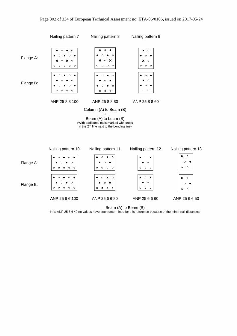
Page 302 of 334 of European Technical Assessment no. ETA-06/0106, issued on 2017-05-24
Nailing pattern 7 Nailing pattern 8 Nailing pattern 9
Flange A:
Flange B:
ANP 25 8 8 100 ANP 25 8 8 80 ANP 25 8 8 60
Column (A) to Beam (B) +
Beam (A) to beam (B) (With additional nails marked with cross in the 2nd line next to the bending line)
Nailing pattern 10 Nailing pattern 11 Nailing pattern 12 Nailing pattern 13
Flange A:
Flange B:
ANP 25 6 6 100 ANP 25 6 6 80 ANP 25 6 6 60 ANP 25 6 6 50
Beam (A) to Beam (B) Info: ANP 25 6 6 40 no values have been determined for this reference because of the minor nail distances.

Page 303 of 334 of European Technical Assessment no. ETA-06/0106, issued on 2017-05-24
Table D54-1 Characteristic capacity timber column to timber beam – 2 Angle Brackets
Flange A
(Column)
Flange B
(Beam)CNA 4.0x40 CNA 4.0x50 CNA 4.0x60 CNA 4.0x40 CNA 4.0x50 CNA 4.0x60
ANP 25 10 10 100 Nailing pattern 4 8 8 6,48 8,3 9,64 9,56 11,8 12,96
ANP 25 10 10 80 Nailing pattern 5 6 6 5,46 6,5 7,16 5,96 7,38 8,16
ANP 25 10 10 60 Nailing pattern 6 5 5 3,88 4,96 6,04 4,9 6,06 6,68
ANP 25 8 8 100 Nailing pattern 7 5 8 6,44 8,14 9,74 7,26 8,9 9,66
ANP 25 8 8 80 Nailing pattern 8 4 6 5,34 6,6 7,26 5,14 6,42 7,02
ANP 25 8 8 60 Nailing pattern 9 3 5 3,88 4,9 5,92 3,16 3,88 4,22
ANP 25 10 20 100 Nailing pattern 1 13 10 7,18 9,56 11,96 11,2 13,74 14,92
ANP 25 6 10 60 Nailing pattern 2 4 5 3,94 5,26 6,58 3,08 3,78 4,1
Number of Fasteners
2 Angle Brackets ANP per connection Characteristic capacity per connection (kN)
R2/3,kR1,k
Model No. Nailing pattern
Table D54-2 Characteristic capacity timber beam to timber beam – 2 Angle Bracket
Flange A
(Beam)
Flange B
(Beam)CNA 4.0x40 CNA 4.0x50 CNA 4.0x60 CNA 4.0x40 CNA 4.0x50 CNA 4.0x60
ANP 25 10 10 100 Nailing pattern 4 10 8 6,48 8,3 9,64 11,02 13,64 15
ANP 25 10 10 80 Nailing pattern 5 8 6 5,46 6,5 7,16 7,76 9,64 10,6
ANP 25 10 10 60 Nailing pattern 6 6 5 3,88 4,96 6,04 5,86 7,22 7,88
ANP 25 8 8 100 Nailing pattern 7 7 8 6,44 8,14 9,74 9,2 11,46 12,7
ANP 25 8 8 80 Nailing pattern 8 6 6 5,34 6,6 7,26 7,28 8,98 9,9
ANP 25 8 8 60 Nailing pattern 9 4 5 3,88 4,9 5,92 3,96 4,94 5,54
ANP 25 6 6 100 Nailing pattern 10 5 5 5,9 7,84 9,26 7,96 9,94 11,06
ANP 25 6 6 80 Nailing pattern 11 4 4 5,12 6,28 7,42 6,02 7,5 8,42
ANP 25 6 6 60 Nailing pattern 12 3 3 3,6 4,8 5,7 3,38 4,2 4,68
ANP 25 6 6 50 Nailing pattern 13 2 2 2,82 3,4 3,96 2,88 3,58 3,96
ANP 25 10 20 100 Nailing pattern 1 16 10 7,18 9,56 11,96 13,14 16,14 17,52
ANP 25 6 10 60 Nailing pattern 2 6 5 3,94 5,26 6,58 5,74 7,1 7,7
ANP 25 4 6 60 Nailing pattern 3 3 3 3,48 4,64 5,8 3,74 4,68 5,32
Number of Fasteners
2 Angle Brackets ANP
per connectionCharacteristic capacity per connection (kN)
R2/3,kR1,k
Model No. Nailing pattern

Page 304 of 334 of European Technical Assessment no. ETA-06/0106, issued on 2017-05-24
Annex D55 – A-brackets
Product Name:
Product
Name
Material reference
acc. to clause II-1 Alternative product names
A21 Steel ref. 4, G90 -
A23 Steel ref. 4, G90 -
A33 Steel ref. 4, G90 -
A88 Steel ref. 4, G90 -
A21S Steel ref. 2 -
A23S Steel ref. 2 -
A33S Steel ref. 2 -
A88S Steel ref. 2 -
A21S2 Steel ref. 3 -
A23S2 Steel ref. 3 -
A33S2 Steel ref. 3 -
A88S2 Steel ref. 3 -
Connector Size Range:
Model no. Dimensions [mm] Holes flange A Holes flange B
A B C Thickness Ø4 Ø4,34 Ø11,1 Ø4 Ø4,34 Ø11,1
A21 38 50,8 35 1,2 - 2 - - 2 -
A23 38 50,8 70 1,2 - 4 - - 4 -
A33 74,6 77,8 38 2,5 4 - - 4 - -
A88 203,2 203,2 51 2,5 4 - 3 4 - 3
Drawing:
A21 A23

Page 305 of 334 of European Technical Assessment no. ETA-06/0106, issued on 2017-05-24
A33 A88
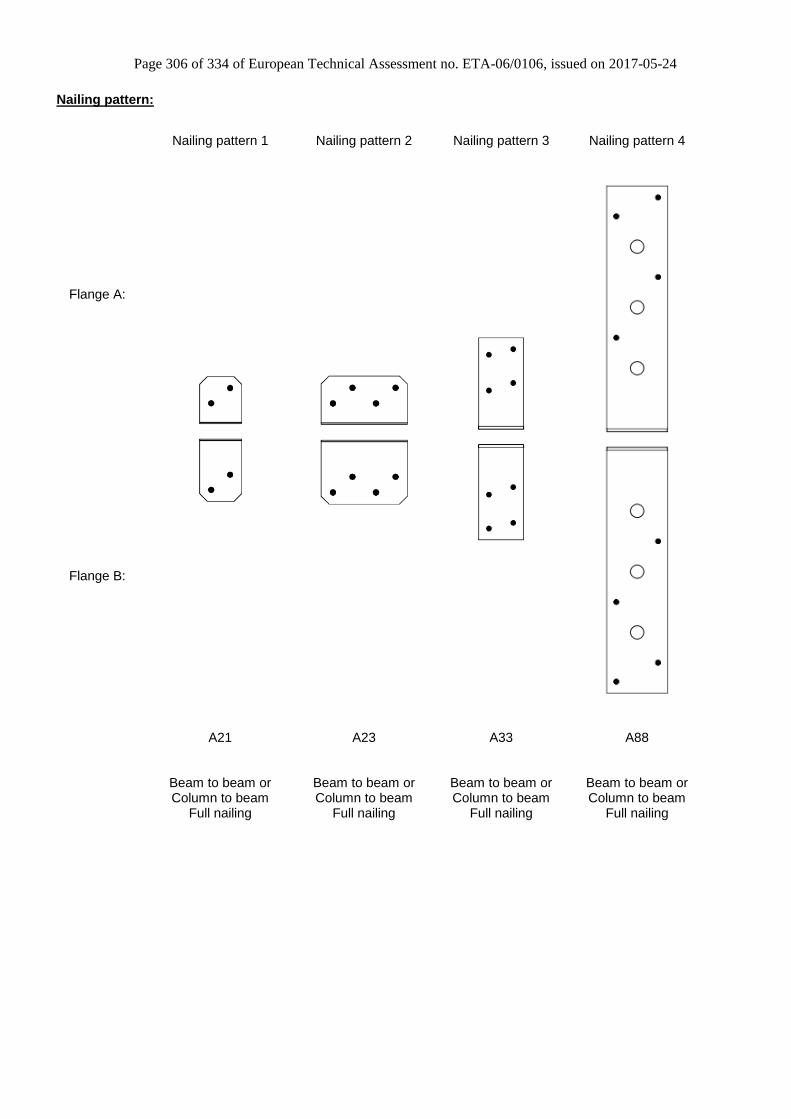
Page 306 of 334 of European Technical Assessment no. ETA-06/0106, issued on 2017-05-24
Nailing pattern:
Nailing pattern 1 Nailing pattern 2 Nailing pattern 3 Nailing pattern 4
Flange A:
Flange B:
A21 A23 A33 A88
Beam to beam or Column to beam
Full nailing
Beam to beam or Column to beam
Full nailing
Beam to beam or Column to beam
Full nailing
Beam to beam or Column to beam
Full nailing

Page 307 of 334 of European Technical Assessment no. ETA-06/0106, issued on 2017-05-24
Characteristic Capacities under vertically upward load (F1)
For the types A21 and A23 the following formula needs to be used: Therefore the values R1,k are stated in the table below.
For the types A33 and A88 the following formula needs to be used: The values R1,k + power + Rk,steel are stated in Table D55-1 below.
Characteristic Capacities under horizontal load (F2/3) For F2/3-horizontal force the following formula needs to be used: The values R2/3,k are stated in Table D55-1 below.
Characteristic Capacities under horizontal load (F4/5) For F4/5-horizontal force the following formula needs to be used: The values for R4/5,k connected with 2 angle brackets and for R4,k / R5,k connected with 1 angle bracket are stated in Table D55-1 below. Supported Memer with a minimum width bt=60mm. The load capacities R4,k are split in two; with and without rotation of purlin.
Table D55-1 Characteristic capacity timber beam to timber beam or timber column to timber beam – 1 Angle
Bracket
Flange A Flange B N3.75x30 N3.75x75 2) Power N3.75x30 N3.75x75
A21 Nailing pattern 1 2 2 0,24 - - - 0,35 -
A23 Nailing pattern 2 4 4 0,48 - - - 1,09 -
A33 Nailing pattern 3 4 4 - 1,15 0,25 1,04 - 2,30
A88 Nailing pattern 4 4 4 - 0,57 1 0,57 - 2,161) Characteristic Capacities have been determined in accordance w ith EN14358 and are based on C24 timber2) The Characteristic Capacities R1,k and R4/5,k connected w ith smooth shank nails N3.75x75 shall only be used for short load durations!
Nailing pattern
1 Angle Bracket A
with min bt = 60 mm per connection
Model No. Rk.steel
R1,k 1) R2/3,k
1) Number of Fasteners
Characteristic capacity per connection (kN)
3,1
mod,1,1
k
kR
dR
3,1;
3,1
modmin,1
,
mod
,1 steelk
power
k Rk
k
R
dR
3,1
mod,3/2,3/2
k
kR
dR
3,1
mod,5/4,5/4
k
kR
dR

Page 308 of 334 of European Technical Assessment no. ETA-06/0106, issued on 2017-05-24
Table D55-2 Characteristic capacity timber beam to timber beam or timber column to timber beam – 1 Angle
Bracket
e (mm) with rotationwithout
rotatione (mm) with rotation
without
rotatione (mm) (kN) e (mm) (kN)
50 0.066 / kmod 50 0,23
100 0.033 / kmod - - - 100 0,13 - -
150 0.022 / kmod 150 0,08
50 0.131 / kmod 50 0,46
100 0.066 / kmod - - - 100 0,25 - -
150 0.044 / kmod 150 0,17
50 0.28 / kmod 50 1.0 / kmod 0.5
- - - 100 0.14 / kmod - - 100 0,70
150 0.10 / kmod 150 0,47
50 0,34 50 0.57 / kmod
- - - 100 0.20 / kmod - - 100 0.55 / kmod 0.5
150 0.13 / kmod 150 0,471) Characteristic Capacities have been determined in accordance w ith EN14358 and are based on C24 timber2) The Characteristic Capacities R1,k and R4/5,k connected w ith smooth shank nails N3.75x75 shall only be used for short load durations!
Nailing
pattern 4
1 Angle Bracket A
with min bt = 60 mm per connection
Flange A Flange B
Characteristic capacity per connection (kN)
Nailing
pattern 3
A88
A33
4 4 2,60
4 4 1,70
4 4
Nailing
patternModel No.
Nailing
pattern 1
Nailing
pattern 2
R5,k 1)
N3.75x30 N3.75x75 2)
Number of Fasteners R4,k 1)
N3.75x75 2)
A23
A21
2,00
N3.75x30
2 2 0,92
Table D55-3 Characteristic capacity timber beam to timber beam or timber column to timber beam – 2 Angle
Brackets
e (mm) (kN) e (mm) (kN)
50 1,15
100 1,05 - -
150 1,00
50 2,15
100 1,95 - -
150 1,85
50 2,95
- - 100 2,70
150 2,47
50 3,20
- - 100 3,15
150 3,101) Characteristic Capacities have been determined in accordance w ith EN14358 and are based on C24 timber2) The Characteristic Capacities R1,k and R4/5,k connected w ith smooth shank nails N3.75x75 shall only be used for short load durations!
Nailing
pattern 4
2 Angle Brackets A per connection
Flange A Flange B
Nailing
pattern 3
A88
A33
4 4
4 4
4 4
Nailing
pattern 2
Number of Fasteners
A23
A21
R4/5,k 1)
N3.75x30 N3.75x75 2)
2 2
Characteristic capacity per connection (kN)
Nailing
patternModel No.
Nailing
pattern 1

Page 309 of 334 of European Technical Assessment no. ETA-06/0106, issued on 2017-05-24
Annex D56 – ABR98 & ABRL98
Product Name:
Product
Name
Material reference
acc. to clause II-1 Alternative product names
ABR98 Steel ref. 1 -
ABRL98 Steel ref. 1 -
ABR98S Steel ref. 2 -
ABRL98S Steel ref. 2 -
ABR98S2 Steel ref. 3 -
ABRL98S2 Steel ref. 3 -
Connector Size Range:
Model no.
Dimensions [mm] Holes flange A Holes flange B
A B C Thickness Ø5 Ø13 Oblong
40x13 Ø5 Ø13
ABR98 98 98 88 3,0 10 3 0 12 3
ABRL98 98 98 88 3,0 10 2 1 12 3
Drawings:
ABR98 ABRL98
Nailing pattern:
Nailing pattern 1 Nailing pattern 2 Nailing pattern 3
Flange A:
Flange B:
Beam to beam
Minimum nailing ABR98 & ABRL98
Beam to beam Maximum nailing
ABR98 & ABRL98
Rigid to rigid ABR98 & ABRL98
4 Dimples (optional)

Page 310 of 334 of European Technical Assessment no. ETA-06/0106, issued on 2017-05-24
Table D56-1 Characteristic capacity beam to beam – 2 Angle Brackets
Flange A Flange B 35 40 50 60 35 40 50 60 35 40 50 60
11,2 12,5 14,2 14,7
10,6 11,8 13,3 13,6
10,4 11,5 12,9 13,1
14,9 15,5 16,5 17,1
13,6 13,9 14,4 14,9
13,1 13,3 13,7 14
F4/5,k 1)
150
100
50
150
100
50
19,7 12,1 13,7 17,5 19,8Nailing
pattern 210 12 9,8 11,8 15,7
10,8 6 6,9 8,8 9,7Nailing
pattern 14 6 5,9 7 9
2 Angle Brackets ABR98 or
ABRL98 per connection
Characteristic capacity (kN) per connection
F1,k
Nailing
pattern
Number of fasteners CNA Connector Nail 4,0 x ℓ
e
(mm)
F2/3,k
1) Minimum width of timber member bt = 60 mm Regarding F2/3 – other fasteners may be used using the following formula and factors. Alternatively, the values from above table can be reduced accordingly:
Table D56-2: Characteristic capacity timber beam to rigid support – 2 Angle Brackets
2 Angle Brackets ABR98 or ABRL98 per
connection
Characteristic capacity (kN)
per connection
Nailing pattern Number of fasteners
R1,k Flange A Flange B
Nailing pattern 3 1 M12 Bolt 2 M12 Bolts2)
17,31)
1) kmod =1,0 for all load durations. 2) For each bolt it must be checked that: Rbolt,ax,d ≥ 0,5 x F1,d
Factor Nailing
pattern 1 Nailing
pattern 2
klat.v 2,1 4,3
kax.v 41,3 30,7
klat.h 2,9 5,4
kax.h 6,2 13,3
2
..
2
..
2
..
2
..
,3/2
11
1
11
1
min
kaxhaxklathlat
kaxvaxklatvlat
k
RkRk
RkRkR

Page 311 of 334 of European Technical Assessment no. ETA-06/0106, issued on 2017-05-24
Annex D57 – AB105/513
Product Name:
Product
Name
Material reference
acc. to clause II-1 Alternative product names
AB105/513 Steel ref. 1 -
AB105/513S Steel ref. 2 -
AB105/513S2 Steel ref. 3 -
Connector Size Range:
Model no. Dimensions [mm] Holes flange A Holes flange B
A B C Thickness Ø5 Ø13 Ø5 Ø13
AB105/513 105 105 90 3,0 14 3 14 2
Drawing:
AB105/513 Washer
Nailing pattern:
Nailing pattern 1
Flange A:
Flange B:
Beam (A) to rigid (B)

Page 312 of 334 of European Technical Assessment no. ETA-06/0106, issued on 2017-05-24
Table D57-1 Characteristic capacity timber beam to rigid – 1 Angle Bracket
5 nails Ø 4,0 Normal 1) n x Rlat,k 10,1/kmod
or 5 CSA5,0 x l Special 2) n x Rlat,k x 0,8 10,1/kmod
1) Normal = spacing of nails accoding to EN 1995-1-1
2) Special = spacing of nails according to figure below
Nailing pattern 1 1 bolt Ø12mm
1 Angle Bracket ABR105/513 per connection
min. of
Nailing pattern
R1,kNumber of Fasteners
Characteristic capacity
per connection (kN)
CNA4,0xl or CSA5,0xl
Flange A Flange B
Installation
The washer with t ≥ 8 mm has to fulfil the minimum requirement: steel with fy,k ≥ 235 N/mm²
With:
n = number of nails Rlat,k = characteristic lateral Load-carrying capacity of one connector nail / screw
It is to check additionally for the anchorage: Rbolt,ax,d ≥ F1,d x 1,47
With:
Rbolt,ax,d = the axial design capacity of the anchor / bolt
25
20
15
F1
nails for fixingthe cipbaord
nails for fixingthe angle bracket

Page 313 of 334 of European Technical Assessment no. ETA-06/0106, issued on 2017-05-24
Annex D58 – ABR255
Product Name:
Product
Name
Material reference
acc. to clause II-1 Alternative product names
ABR255 Steel ref. 1 -
ABR255S Steel ref. 2 -
ABR255S2 Steel ref. 3 -
Connector Size Range:
Model no. Dimensions [mm] Holes flange A Holes flange B
A B C Thickness Ø5 Ø14 Ø5 Ø14
ABR255 120 100 255 3,0 52 2 41 4
Drawing:

Page 314 of 334 of European Technical Assessment no. ETA-06/0106, issued on 2017-05-24
Nailing pattern:
Nailing pattern 1 Nailing pattern 2
Flange A:
Flange B: (Timber)
Flange B: (Rigid)
Beam (A) to Beam/Rigid (B)
Maximum nailing Beam (A) to Beam/Rigid (B)
Minimum nailing
Nailing pattern 3
Flange A:
Flange B: (Timber)
Flange B: (Rigid)
Column (A) to Beam/Rigid (B)
Maximum nailing
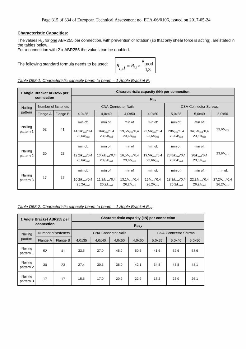
Page 315 of 334 of European Technical Assessment no. ETA-06/0106, issued on 2017-05-24
Characteristic Capacities:
The values Ri,k for one ABR255 per connection, with prevention of rotation (so that only shear force is acting), are stated in the tables below. For a connection with 2 x ABR255 the values can be doubled.
The following standard formula needs to be used:
Table D58-1: Characteristic capacity beam to beam – 1 Angle Bracket F1
Flange A Flange B 4,0x35 4,0x40 4,0x50 4,0x60 5,0x35 5,0x40 5,0x50
Nailing
pattern 152 41
min of:
14,1/kmod^0,4
23,6/kmod
min of:
16/kmod^0,4
23,6/kmod
min of:
19,5/kmod^0,4
23,6/kmod
min of:
22,5/kmod^0,4
23,6/kmod
min of:
28/kmod^0,4
23,6/kmod
min of:
34,5/kmod^0,4
23,6/kmod
23,6/kmod
Nailing
pattern 230 23
min of:
12,2/kmod^0,4
23,6/kmod
min of:
13,7/kmod^0,4
23,6/kmod
min of:
16,5/kmod^0,4
23,6/kmod
min of:
19,5/kmod^0,4
23,6/kmod
min of:
23,8/kmod^0,4
23,6/kmod
min of:
28/kmod^0,4
23,6/kmod
23,6/kmod
Nailing
pattern 317 17
min of:
10,2/kmod^0,4
26,2/kmod
min of:
11,2/kmod^0,4
26,2/kmod
min of:
13,1/kmod^0,4
26,2/kmod
min of:
15/kmod^0,4
26,2/kmod
min of:
18,3/kmod^0,4
26,2/kmod
min of:
22,3/kmod^0,4
26,2/kmod
min of:
27,2/kmod^0,4
26,2/kmod
Nailing
pattern
Number of fasteners CNA Connector Nails CSA Connector Screws
1 Angle Bracket ABR255 per
connection
Characteristic capacity (kN) per connection
R1,k
Table D58-2: Characteristic capacity beam to beam – 1 Angle Bracket F2/3
Flange A Flange B 4,0x35 4,0x40 4,0x50 4,0x60 5,0x35 5,0x40 5,0x50
Nailing
pattern 152 41 33,5 37,0 45,9 50,5 41,6 52,6 58,6
Nailing
pattern 230 23 27,4 30,5 38,0 42,1 34,8 43,8 48,1
Nailing
pattern 317 17 15,5 17,0 20,9 22,9 18,2 23,0 26,1
1 Angle Bracket ABR255 per
connection
Characteristic capacity (kN) per connection
R2/3,k
Nailing
pattern
Number of fasteners CNA Connector Nails CSA Connector Screws
3,1
mod, ,
kR
diR ki

Page 316 of 334 of European Technical Assessment no. ETA-06/0106, issued on 2017-05-24
Table D58-3: Characteristic capacity beam to rigid support – 1 Angle Bracket F1
Flange A Flange B 4,0x35 4,0x40 4,0x50 4,0x60 5,0x35 5,0x40 5,0x50
Nailing
pattern 152
2 x M12
Bolts
min of:
36,8
22/kmod
min of:
43,3
22/kmod
min of:
56,7
22/kmod
min of:
67,9
22/kmod
min of:
72,3
22,/kmod
min of:
92,5
22/kmod
min of:
109,8
22/kmod
Nailing
pattern 230
2 x M12
Bolts
min of:
15,94
22/kmod
min of:
18,8
22/kmod
min of:
24,8
22/kmod
min of:
30,3
22/kmod
min of:
35,1
22,/kmod
min of:
45,2
22/kmod
min of:
56
22/kmod
Nailing
pattern 317
2 x M12
Bolts
min of:
15,3
22/kmod
min of:
17,9
22/kmod
min of:
23,1
22/kmod
min of:
27
22/kmod
min of:
26,4
22,/kmod
min of:
33,6
22/kmod
min of:
38,7
22/kmod
1 Angle Bracket ABR255 per
connection
Characteristic capacity (kN) per connection
R1,k
Nailing
pattern
Number of fasteners CNA Connector Nails CSA Connector Screws
The bolts have to be checked for:
1,1,1,,1 ddbolt RF
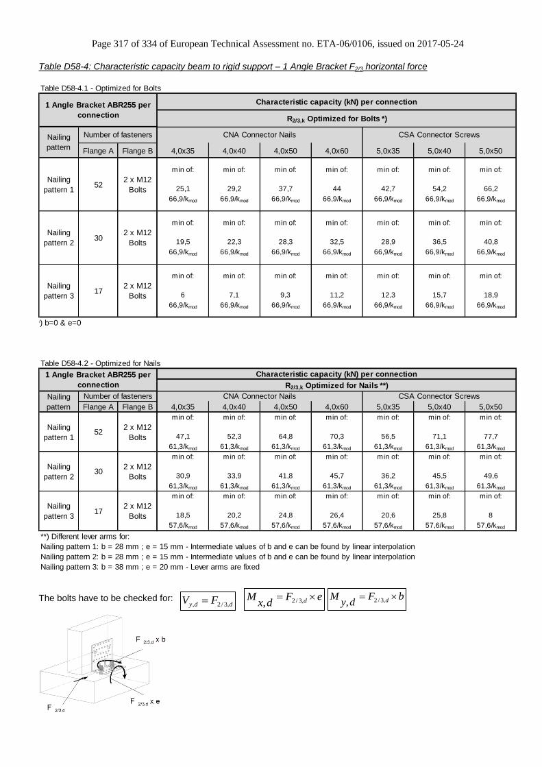
Page 317 of 334 of European Technical Assessment no. ETA-06/0106, issued on 2017-05-24
ddy FV ,3/2, eFdx
M d ,3/2,bF
dyM d ,3/2,
Table D58-4: Characteristic capacity beam to rigid support – 1 Angle Bracket F2/3 horizontal force
Table D58-4.1 - Optimized for Bolts
Flange A Flange B 4,0x35 4,0x40 4,0x50 4,0x60 5,0x35 5,0x40 5,0x50
Nailing
pattern 152
2 x M12
Bolts
min of:
25,1
66,9/kmod
min of:
29,2
66,9/kmod
min of:
37,7
66,9/kmod
min of:
44
66,9/kmod
min of:
42,7
66,9/kmod
min of:
54,2
66,9/kmod
min of:
66,2
66,9/kmod
Nailing
pattern 230
2 x M12
Bolts
min of:
19,5
66,9/kmod
min of:
22,3
66,9/kmod
min of:
28,3
66,9/kmod
min of:
32,5
66,9/kmod
min of:
28,9
66,9/kmod
min of:
36,5
66,9/kmod
min of:
40,8
66,9/kmod
Nailing
pattern 317
2 x M12
Bolts
min of:
6
66,9/kmod
min of:
7,1
66,9/kmod
min of:
9,3
66,9/kmod
min of:
11,2
66,9/kmod
min of:
12,3
66,9/kmod
min of:
15,7
66,9/kmod
min of:
18,9
66,9/kmod
*) b=0 & e=0
Table D58-4.2 - Optimized for Nails
Flange A Flange B 4,0x35 4,0x40 4,0x50 4,0x60 5,0x35 5,0x40 5,0x50
Nailing
pattern 152
2 x M12
Bolts
min of:
47,1
61,3/kmod
min of:
52,3
61,3/kmod
min of:
64,8
61,3/kmod
min of:
70,3
61,3/kmod
min of:
56,5
61,3/kmod
min of:
71,1
61,3/kmod
min of:
77,7
61,3/kmod
Nailing
pattern 230
2 x M12
Bolts
min of:
30,9
61,3/kmod
min of:
33,9
61,3/kmod
min of:
41,8
61,3/kmod
min of:
45,7
61,3/kmod
min of:
36,2
61,3/kmod
min of:
45,5
61,3/kmod
min of:
49,6
61,3/kmod
Nailing
pattern 317
2 x M12
Bolts
min of:
18,5
57,6/kmod
min of:
20,2
57,6/kmod
min of:
24,8
57,6/kmod
min of:
26,4
57,6/kmod
min of:
20,6
57,6/kmod
min of:
25,8
57,6/kmod
min of:
8
57,6/kmod
**) Different lever arms for:
Nailing pattern 1: b = 28 mm ; e = 15 mm - Intermediate values of b and e can be found by linear interpolation
Nailing pattern 2: b = 28 mm ; e = 15 mm - Intermediate values of b and e can be found by linear interpolation
Nailing pattern 3: b = 38 mm ; e = 20 mm - Lever arms are fixed
1 Angle Bracket ABR255 per
connection
Characteristic capacity (kN) per connection
R2/3,k Optimized for Nails **)
Nailing
pattern
Number of fasteners CNA Connector Nails CSA Connector Screws
1 Angle Bracket ABR255 per
connection
Characteristic capacity (kN) per connection
R2/3,k Optimized for Bolts *)
Nailing
pattern
Number of fasteners CNA Connector Nails CSA Connector Screws
The bolts have to be checked for:

Page 318 of 334 of European Technical Assessment no. ETA-06/0106, issued on 2017-05-24
Table D58-5: ABR255 Slip modulus Kser – timber to rigid
Flange A Flange B 4,0x35 4,0x40 4,0x50 4,0x60 5,0x35 5,0x40 5,0x50 4,0x35 4,0x40 4,0x50 4,0x60 5,0x35 5,0x40 5,0x50
Nailing
pattern 152
2 x M12
Bolts6,1 7,2 9,4 11,3 12,0 15,4 18,3 8,5 9,5 11,7 12,7 10,2 12,9 14,1
Nailing
pattern 230
2 x M12
Bolts2,6 3,1 4,1 5,0 5,8 7,5 9,3 5,6 6,1 7,6 8,3 6,6 8,2 9,0
Nailing
pattern 317
2 x M12
Bolts2,5 3,0 3,8 4,5 4,4 5,6 6,4 3,3 3,7 4,5 4,8 3,7 4,7 5,1
For force F2
CNA Connector Nails CSA Connector Screws
Slip modulus kser (kN/mm)1 Angle Bracket ABR255 per
connection For force F1
Nailing
pattern
Number of fasteners CNA Connector Nails CSA Connector Screws
Table D58-6: ABR255 Slip modulus Kser – timber to timber
Flange A Flange B 4,0x35 4,0x40 4,0x50 4,0x60 5,0x35 5,0x40 5,0x50 4,0x35 4,0x40 4,0x50 4,0x60 5,0x35 5,0x40 5,0x50
Nailing
pattern 152 41 6,9 7,9 9,6 11,1 13,8 17,0 - 4,6 5,1 6,3 6,9 5,7 7,2 8,0
Nailing
pattern 230 23 6,0 6,7 8,1 9,6 11,7 13,8 - 3,8 4,2 5,2 5,8 4,8 6,0 6,6
Nailing
pattern 317 17 5,0 5,5 6,4 7,4 9,0 11,0 13,4 2,1 2,3 2,9 3,1 2,5 3,1 3,6
1 Angle Bracket ABR255 per
connection
Slip modulus kser (kN/mm)
For force F1 For force F2
Nailing
pattern
Number of fasteners CNA Connector Nails CSA Connector Screws CNA Connector Nails CSA Connector Screws

Page 319 of 334 of European Technical Assessment no. ETA-06/0106, issued on 2017-05-24
Annex D59 – ABD45100 & ABDW45100
Product Name:
Product Name Material reference
acc. to clause II-1 Alternative product names
ABD45100 Steel ref. 1 -
ABDW45100 Steel ref. 1 -
ABD45100S Steel ref. 2 -
ABDW45100S Steel ref. 2 -
ABD45100S2 Steel ref. 3 -
ABDW45100S2 Steel ref. 3 -
Connector Size Range:
Model no. Dimensions [mm] Holes flange A Holes flange B
A B C Thickness Ø5 Ø5 Ø13x21
ABD45100 ABDW45100
100 45 55 3,0 10 4 1
Washer - 40 50 10 0 0 1
Drawing:
ABD45100 Washer ABDW45100

Page 320 of 334 of European Technical Assessment no. ETA-06/0106, issued on 2017-05-24
Nailing pattern:
Nailing
pattern 1 Nailing
pattern 2 Nailing
pattern 3 Nailing
pattern 4 Nailing
pattern 5 Nailing
pattern 6
Flange A:
Flange B:
Beam to
beam Beam to
beam Beam to
beam Beam (A) to
rigid (B) Beam (A) to
rigid (B) Beam (A) to
rigid (B)
Table D59-1: Characteristic capacity 1 Angle Bracket
Nailing
pattern 110 4 Min of: Min of:
Nailing
pattern 25 4 1,47 1,96
Nailing
pattern 35 4 21,2 / ((f+15) x kmod) 21,2 / ((f+15) x kmod)
Nailing
pattern 410 1 Bolt
Nailing
pattern 55 1 Bolt
Nailing
pattern 65 1 Bolt
The necessary capacity of bolt has to be as minimum:
Rbolt.axial = F1.d x (40 mm + f ) / 23 mm
f in [mm]
1 Angle Bracket
ABD45100/ABDW45100 per
connection
Characteristic capacities R1,k [kN] per connection
CNA connector nailsNumber of fasteners
4,0x35 4,0x40 4,0x50 4,0x60
21,2 / ((f+15) x kmod) 21,2 / ((f+15) x kmod)
36,5 / ((f + 6 ) x kmod)
Nailing
pattern Flange A Flange B

Page 321 of 334 of European Technical Assessment no. ETA-06/0106, issued on 2017-05-24
Table D59-2: Characteristic capacity 2 Angle Brackets
Nailing
pattern 110 4 2,94 3,92 4,9 5,81 6,07 7,01 8,86 10,18
Nailing
pattern 25 4 2,94 3,92 4,9 5,81 5,65 6,22 7,47 8,12
Nailing
pattern 35 4 2,94 3,92 4,9 5,81 3,49 3,82 4,57 4,94
Nailing
pattern 410 1 Bolt 16,2/kmod 16,2/kmod 16,2/kmod 16,2/kmod 4,82 6,26 7,51 8,58
Nailing
pattern 55 1 Bolt 15,4/kmod 16,2/kmod 16,2/kmod 16,2/kmod 4,1 5,2 6,05 6,73
Nailing
pattern 65 1 Bolt 16,2/kmod 16,2/kmod 16,2/kmod 16,2/kmod 1,3 1,7 2,05 2,36
2 Angle Brackets
ABD45100/ABDW45100 per
connection
Characteristic capacities [kN] per connection
R2/3,k
CNA connector nails
4,0x35 4,0x40 4,0x50 4,0x604,0x60
R1,k
Characteristic capacities [kN] per connection
Nailing
pattern
Number of fasteners CNA connector nails
Flange A Flange B 4,0x35 4,0x40 4,0x50
The necessary capacity of bolt has to be as minimum:
Rbolt.axial = F1.d x 1.65
Rbolt.axial = F2.d x 0.4 Rbolt.lat = F2
With:
Rbolt.axial = axial capacity of the bolt / both bolts (connection with 1 / 2 ABD )
Rbolt.lat = lateral capacity of the bolt / both bolts (connection with 1 / 2 ABD )
For connection with one ABD, the half of capacities as for connection with 2 ABD can be used, if the timber elements are prevented against rotation.

Page 322 of 334 of European Technical Assessment no. ETA-06/0106, issued on 2017-05-24
Annex D60 – ADR6090L
Product Name:
Product
Name
Material reference
acc. to clause II-1 Alternative product names
ADR6090L Steel ref. 1 -
ADR6090LS Steel ref. 2 -
ADR6090LS2 Steel ref. 3 -
Connector Size Range:
Model no.
Dimensions [mm] Holes flange A Holes flange B
A B C Thickness Ø5 Oblong
12x40
Oblong
5x30 Ø5
Oblong
12x20
Oblong
10,5x20
ADR6090L 89,5 59,5 60 2,0 5 1 1 4 1 1
Drawings:
Nailing pattern:
Nailing pattern 1 Nailing pattern 2
Flange A:
Flange B:
Beam to beam Beam (A) to rigid (B)

Page 323 of 334 of European Technical Assessment no. ETA-06/0106, issued on 2017-05-24
Characteristic Capacities:
The values Ri,k for one ADR6090L per connection are stated in the tables below. For a connection with 2 x ADR6090L the values (“rotation is prevented”) can be doubled.
Table D60-1 Timber to timber - F1 - 1 Angle Bracket
1 x ADR6090L per Connection Characteristic capacity R1,k per connection [kN]
Nailing pattern 1 Flange A: 3 Flange B: 2 Purlin is free to rotate Purlin is prevented to rotate
Fastener
CNA4,0x35 min. [(11/kmod)/(f+20) ; 37/(f+50)] 1,1 / kmod0,3
CNA4,0x40 (11/kmod) / (f+20) 1,3 / kmod0,3
CNA4,0x50 (11/kmod) / (f+20) min. [1,55/kmod0,3
; 1,5/kmod]
CNA4,0x60 (11/kmod) / (f+20) min. [1,8/kmod0,3
; 1,5/kmod]
CSA5,0x35 (11/kmod) / (f+20) 1,5 / kmod
CSA5,0x40 (11/kmod) / (f+20) 1,5 / kmod
CSA5,0x50 (11/kmod) / (f+20) 1,5 / kmod
Table D60-2 Timber to timber – F2/3-horizontal force - 2 Angle Brackets
2 x ADR6090L per Connection
Characteristic capacity
R2/3,k per connection [kN]
Nailing pattern 1 Flange A: 3 Flange B: 2
Fastener
CNA4,0x35 2,7
CNA4,0x40 3,0
CNA4,0x50 3,8
CNA4,0x60 4,2
CSA5,0x35 4,7
CSA5,0x40 5,5
CSA5,0x50 6,6

Page 324 of 334 of European Technical Assessment no. ETA-06/0106, issued on 2017-05-24
Table D60-3 Timber to rigid support - F1
Nailing pattern 2 Flange A: 5
Flange B: 1 Bolt Characteristic capacity R1,k per connection [kN]
Fastener 1 x ADR6090L 2 x ADR6090L
CNA4,0x35 min. [13,6 ; 9,9/kmod] (28/kmod) / (f+30)
CNA4,0x40 min. [9,3 ; 9,9/kmod]
(35/kmod) / (f+30)
CNA4,0x50
9,9 / kmod
CAN 4,0x60
CSA5,0x35
CSA5,0x40
CSA5,0x50
Check of Bolts has to be done separately.
Table D60-4 Timber to rigid support – F2/3 - 2 Angle Brackets
2 x ADR6090L per Connection
Characteristic capacity
R2/3,k per connection [kN] Nailing pattern 2
Flange A: 5 Flange B: 1 Bolt
Fastener
CNA4,0x35 3,6
CNA4,0x40 4,1
CNA4,0x50 5,2
CAN 4,0x60 5,9
CSA5,0x35 5,8
CSA5,0x40 6,6
CSA5,0x50 7,8
Check of Bolts has to be done separately.
Bolt factors:
Bolt
factor
1 x ADR6090L per
connection
2 x ADR6090L per
connection
R1,k R2/3,k R1,k R2/3,k
kax (f+29,5)/10 - 1,13 -
klat - 1 - 0,5
For each Bolt it’s needed to check: Rbolt,ax,d ≥ kax x Fi,d & klat x Fi,d
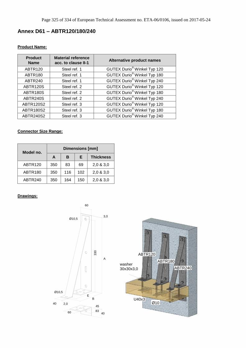
Page 325 of 334 of European Technical Assessment no. ETA-06/0106, issued on 2017-05-24
Annex D61 – ABTR120/180/240
Product Name:
Product
Name
Material reference
acc. to clause II-1 Alternative product names
ABTR120 Steel ref. 1 GUTEX Durio®
Winkel Typ 120
ABTR180 Steel ref. 1 GUTEX Durio®
Winkel Typ 180
ABTR240 Steel ref. 1 GUTEX Durio®
Winkel Typ 240
ABTR120S Steel ref. 2 GUTEX Durio®
Winkel Typ 120
ABTR180S Steel ref. 2 GUTEX Durio®
Winkel Typ 180
ABTR240S Steel ref. 2 GUTEX Durio®
Winkel Typ 240
ABTR120S2 Steel ref. 3 GUTEX Durio®
Winkel Typ 120
ABTR180S2 Steel ref. 3 GUTEX Durio®
Winkel Typ 180
ABTR240S2 Steel ref. 3 GUTEX Durio®
Winkel Typ 240
Connector Size Range:
Model no. Dimensions [mm]
A B E Thickness
ABTR120 350 83 69 2,0 & 3,0
ABTR180 350 116 102 2,0 & 3,0
ABTR240 350 164 150 2,0 & 3,0
Drawings:
60
330
83
45
3,0Ø10,5
A
2,040
Ø10,5
BE
4060
ABTR120
ABTR180
ABTR240
U40x3
washer30x30x3,0
Ø10

Page 326 of 334 of European Technical Assessment no. ETA-06/0106, issued on 2017-05-24
Assignment:
Type Single Components
ABTR120 AB35, TR12, AB4
ABTR180 AB35, TR18, AB4
ABTR240 AB35, TR24, AB4
U40x3
Washer 30x30x3,0 (DIN436)
AB35
AB4
TR24TR18
TR12
U40x3
AB35
AB35
washer30x30x3,0
Ø10
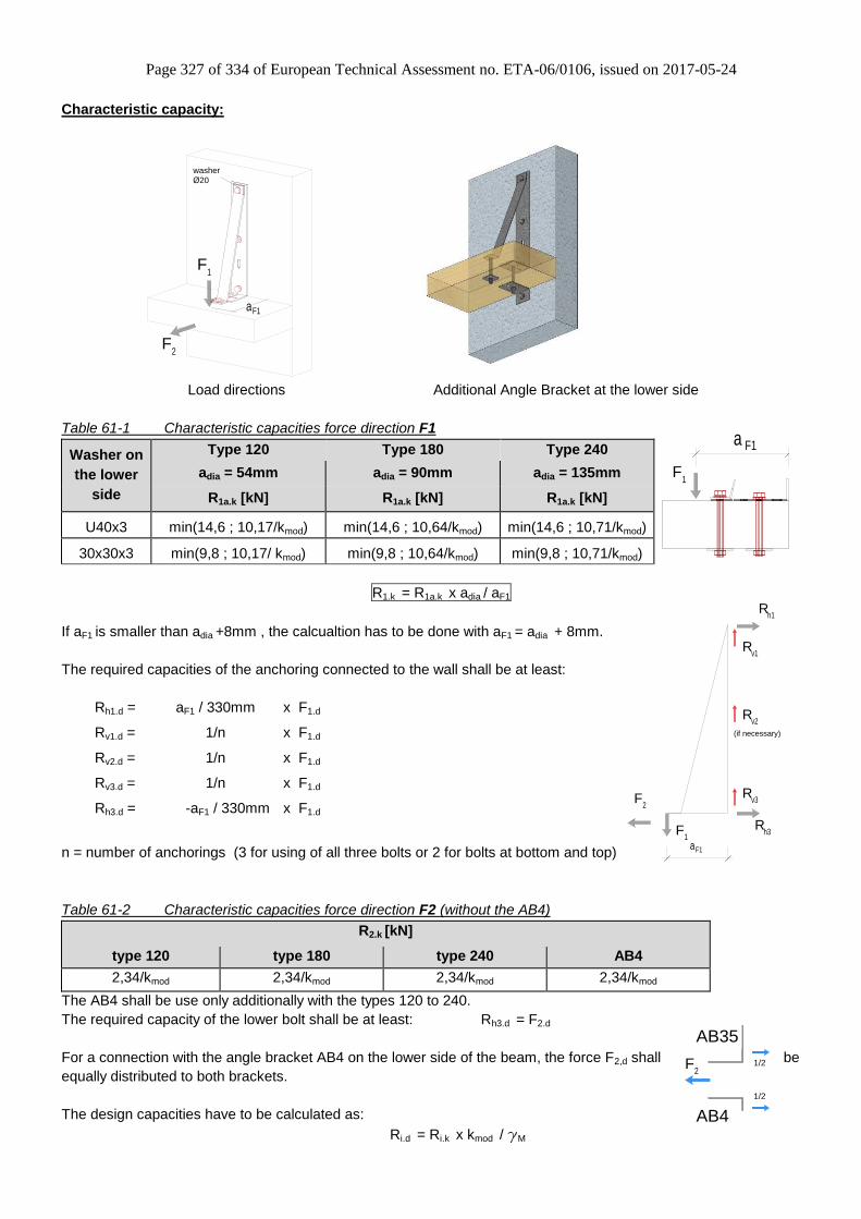
Page 327 of 334 of European Technical Assessment no. ETA-06/0106, issued on 2017-05-24
Characteristic capacity:
2F
1 F
aF1
washerØ20
Load directions Additional Angle Bracket at the lower side
Table 61-1 Characteristic capacities force direction F1
Washer on
the lower
side
Type 120 Type 180 Type 240
adia = 54mm adia = 90mm adia = 135mm
R1a.k [kN] R1a.k [kN] R1a.k [kN]
U40x3 min(14,6 ; 10,17/kmod) min(14,6 ; 10,64/kmod) min(14,6 ; 10,71/kmod)
30x30x3 min(9,8 ; 10,17/ kmod) min(9,8 ; 10,64/kmod) min(9,8 ; 10,71/kmod)
R1.k = R1a.k x adia / aF1
If aF1 is smaller than adia +8mm , the calcualtion has to be done with aF1 = adia + 8mm.
The required capacities of the anchoring connected to the wall shall be at least:
Rh1.d = aF1 / 330mm x F1.d
Rv1.d = 1/n x F1.d
Rv2.d = 1/n x F1.d
Rv3.d = 1/n x F1.d
Rh3.d = -aF1 / 330mm x F1.d
n = number of anchorings (3 for using of all three bolts or 2 for bolts at bottom and top)
Table 61-2 Characteristic capacities force direction F2 (without the AB4)
R2.k [kN]
type 120 type 180 type 240 AB4
2,34/kmod 2,34/kmod 2,34/kmod 2,34/kmod
The AB4 shall be use only additionally with the types 120 to 240.
The required capacity of the lower bolt shall be at least: Rh3.d = F2.d
For a connection with the angle bracket AB4 on the lower side of the beam, the force F2,d shall be
equally distributed to both brackets.
The design capacities have to be calculated as:
Ri.d = Ri.k x kmod / gM
F 1
F1a
R h1
1 F
v1R
v2R
v3R
R h3
aF1
2 F
(if necessary)
F 2
1/2
1/2
AB4
AB35

Page 328 of 334 of European Technical Assessment no. ETA-06/0106, issued on 2017-05-24
The brackets are intendend to be connected with bolts or screws with
a Ø of 10mm. In case timberscrews are used for fixing, also screws
with a smaller diameter than Ø10 can be applied with a reducer like
the one shown aside. The reducer has to embed into both steel
plates.
For the distances of the bolts in the beam has to be observe the EN1995-1.
The drilling in the beam should be done on site.
Load combination:
F1.d / R1.d ≤ 1 and F2.d / R2.d ≤ 1 check of connector
The loads for the anchoring have to be added up , and have to be checked separately according to the individual
anchoring type.
Application:
The typical installation of the connector may be as follows:
An extra layer is added to an existing wall. Columns are placed
between the horizontal beams, and on these columns are fixed the
outer layer. Insulation is placed between the new outer layer and the
existing wall.
Due to the columns, the rotation of the beams is prevented. The
vertical load can be calculated with a distance (adia + 8mm) from the
wall .
Type adia [mm]
ABTR120 54
ABTR180 90
ABTR240 135
F 1
F1 dia
F 1
resultinghorizontaltension
resultinghorizontalpressure
a + 8mma
h
e
M = F x e 1 1
column
beam
connector
real situation situation for calculation
axis of gravity
Generally the brackets shall be calculated with a lever arm of F1 of aF1 = ( adia + 8mm )
For beam distances h ≥ 2000mm the resulting centering forces can usally be disregarded.
Else all details shall be designed in accordance with EC5.
extra layer
>20

Page 329 of 334 of European Technical Assessment no. ETA-06/0106, issued on 2017-05-24
Annex D62 – ACW155
Product Name:
Product
Name
Material reference
acc. to clause II-1 Alternative product names
ACW155 Steel ref. 1 -
ACW155S Steel ref. 2 -
ACW155S2 Steel ref. 3 -
Connector Size Range:
Model no.
Dimensions [mm] Holes flange A Holes flange B
A B C Thickness Ø5 Ø9 Oblong
13x30 Ø14
Oblong
13x30
ACW155 154 123 150 2,5 33 2 3 4 2
Drawings:
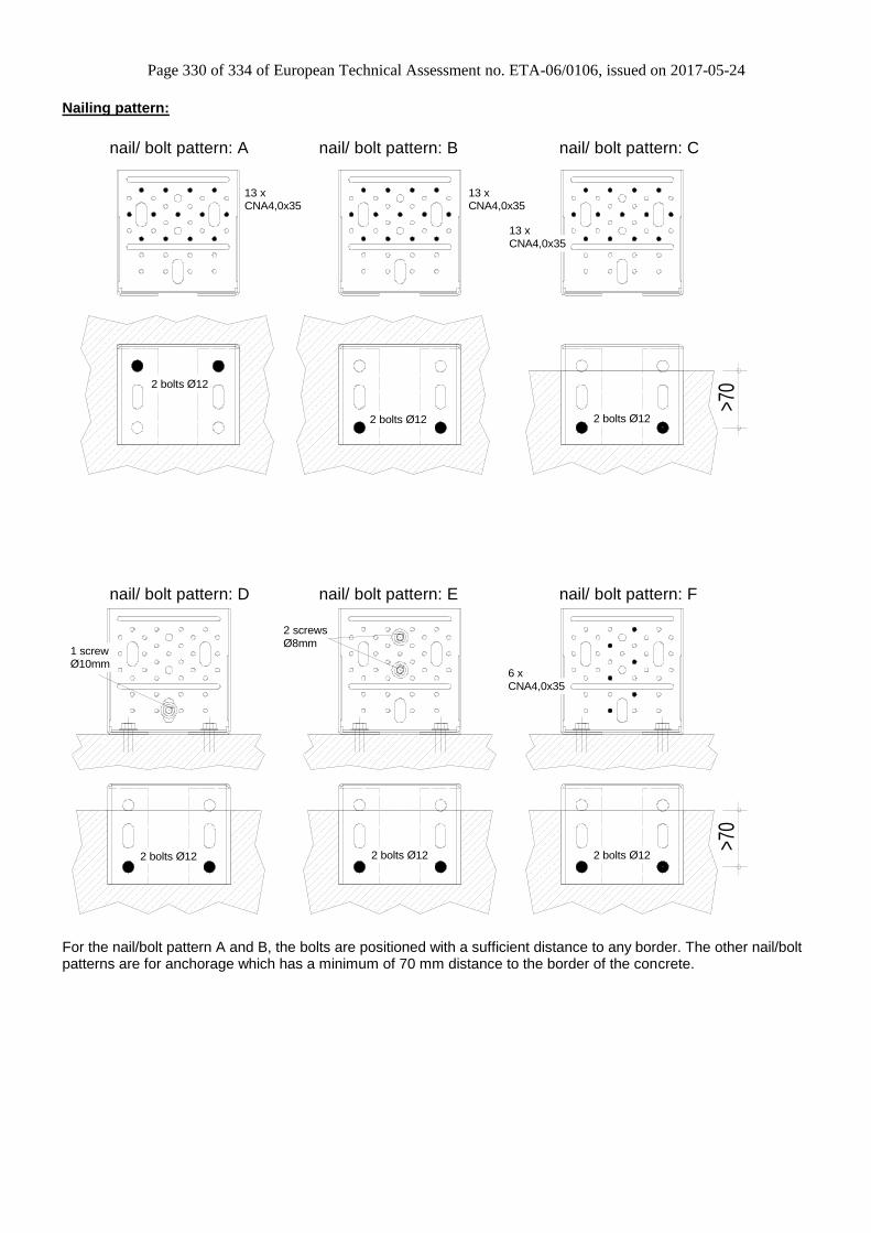
Page 330 of 334 of European Technical Assessment no. ETA-06/0106, issued on 2017-05-24
Nailing pattern:
>70
>70
2 bolts Ø12
2 screws
CNA4,0x35
6 x
1 screw Ø8mm
Ø10mm
13 x
CNA4,0x35
2 bolts Ø12
2 bolts Ø12
nail/ bolt pattern: B
13 x
CNA4,0x35
nail/ bolt pattern: A nail/ bolt pattern: C
13 x
CNA4,0x35
2 bolts Ø122 bolts Ø12
nail/ bolt pattern: Fnail/ bolt pattern: Enail/ bolt pattern: D
2 bolts Ø12
For the nail/bolt pattern A and B, the bolts are positioned with a sufficient distance to any border. The other nail/bolt patterns are for anchorage which has a minimum of 70 mm distance to the border of the concrete.

Page 331 of 334 of European Technical Assessment no. ETA-06/0106, issued on 2017-05-24
For nailing patterns B to F, the connected timber elements are free to rotate as the connected elements are fixed at minimum to one other point.
For the nailing patterns D to F, it is determined that a vertical load (F6) is always present.
Load directions:
Table 62-1 Characteristic values
Nailing pattern Number of fasteners Characteristic capacities [kN]
Flange A Flange B R1,k R2/3,k R4,k R5,k R6,k
A 13 CNA4,0x35 2 x M12 Bolts 16,3 15,3 21,1 5 -
B 13 CNA4,0x35 2 x M12 Bolts 8,8 11,9 6 11,4 21,2
C 13 CNA4,0x35 2 x M12 Bolts 8,8 8,9 6 11,4 21,2
D 1 ESCR Ø10x140 2 x M12 Bolts - - 7,5 5,7 -
E 2 ESCR Ø8x100 2 x M12 Bolts - - 7,5 3,92 7,73
F 6 CNA4,0x35 2 x M12 Bolts - - 7,5 2,64 10,1
The fasteners in the joist/beam can be replaced with different fasteners but must as a minimum have the same capacities of the specified fasteners. For the nail pattern A to C to connect the ACW155, other screws can be used but are also required to have a minimum capacity as the same as the specified fasteners. The connections with the nail pattern D to F can be used also for the connection of a column. Load combination: ∑ (Fi.d / Ri.d ) ≤ 1,0
F4
F5
F1 F6
F3F2

Page 332 of 334 of European Technical Assessment no. ETA-06/0106, issued on 2017-05-24
The anchorage must be checked with the following loads: Table 62-2 Bolt factors
Nailing pattern
The anchoring has to be check for following:
for F1 for F2 for F4 for F5 for F6
NSd VySd MxSd MzSd VxSd VxSd NSd NSd
A F1.d x 1.1 F2.d F2.d x 27mm F2.d x 69mm F4.d F5.d F5.d x 3 -
B F1.d x 3,7 F2.d F2.d x 92mm F2.d x 59mm F4.d F5.d F5.d x 1,3 F6.d x 0.7
C F1.d x 3,7 F2.d F2.d x 82mm F2.d x 59mm F4.d F5.d F5.d x 1,3 F6.d x 0.7
D - - - - F4.d F5.d F5.d x 0.7 -
E - - - - F4.d F5.d F5.d x 0.9 F6.d x 0.7
F - - - - F4.d F5.d F5.d x 1.3 F6.d x 0.7
For load combination, the combination for the anchorage must also be checked.
V xSd
V ySd
MzSd
ySdV
MxSdNSd
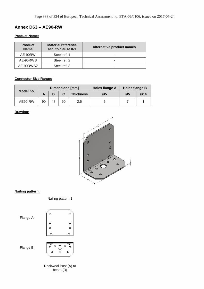
Page 333 of 334 of European Technical Assessment no. ETA-06/0106, issued on 2017-05-24
Annex D63 – AE90-RW
Product Name:
Product
Name
Material reference
acc. to clause II-1 Alternative product names
AE-90RW Steel ref. 1 -
AE-90RWS Steel ref. 2 -
AE-90RWS2 Steel ref. 3 -
Connector Size Range:
Model no. Dimensions [mm] Holes flange A Holes flange B
A B C Thickness Ø5 Ø5 Ø14
AE90-RW 90 48 90 2,5 6 7 1
Drawing:
Nailing pattern:
Nailing pattern 1
Flange A:
Flange B:
Rockwool Post (A) to
beam (B)

Page 334 of 334 of European Technical Assessment no. ETA-06/0106, issued on 2017-05-24
Table D63-1 Characteristic capacity - Composite Metal beam to timber beam – 2 Angle Brackets
2 Angle brackets AE90-RW per connection Characteristic capacity per
connection (kN)
Nailing pattern Number of fasteners
R1,k Flange A Flange B
Nailing pattern 1 2 Self drilling screws Ø5.5x50 8 CSA5.0x40 9.8 / kmod
Glulam GL24 – Minimum section 61x105
Composite Metal Joist Rockwool® Rock Zero