european technical approval...
TRANSCRIPT
ETA-Danmark AS Kollegievej 6 DK-2920 Charlottenlund Tel +45 72 24 59 00 Fax +45 72 24 59 04 Internet wwwetadanmarkdk
MEMBER OF EOTA
Authorised and notified according to Article 10 of the Council Directive 89106EEC of 21 December 1988 on the approximation of laws regulations and administrative provisions of Member States relating to construction products
European Technical Approval ETA-070053
This ETA replaces the previous ETA with the same number and validity from 2011-11-17 to 2016-11-17 Trade name
Simpson Strong-Tie Cantilever Bracket GERB GERC GERW GERG SC SCR and LEA
Holder of approval SIMPSON STRONG-TIE AS Hedegaardsvej 4 ndash 11 Boulstrup DK-8300 Odder Tel +45 87 81 74 00 Fax +45 87 81 74 09 Internet wwwsimpsonstrongtiedk
Generic type and use of con-struction product
Three-dimensional nailing plate (timber to timber cantilever bracket)
Valid from to
2013-04-18 2018-04-18
Manufacturing plant Simpson Strong-Tie AS Hedegaardsvej 4-11 Boulstrup 8300 Odder Denmark
Simpson Strong-Tie ZAC des Quatre Chemins 85400 Sainte Gemme La Plaine France
Simpson Strong-Tie Winchester Road Cardinal Point Tamworth Staffordshire B78 3HG United Kingdom
This European Technical Approval contains
32 pages including 5 annexes which form an integral part of the document
Page 2 of 32 of European Technical Approval no ETA-070053
LEGAL BASIS AND GENERAL CONDITIONS 3
SPECIAL CONDITIONS OF THE EUROPEAN TECHNICAL APPROV AL 4
1 Definition of product and intended use 4
2 Characteristics of product and assessment 6
3 Attestation of Conformity and CE marking 8
Annex A Revision History 11
Annex B Typical Installation 12
Annex C Basis of Design 13
Annex C1 Basis of Design 13
Annex C2 ndash Definition of forces direction 14
Annex C3 ndash Fasteners specification and capacities 14
Annex C4 ndash Characteristic capacity modification method for different timber types 15
Annex D - Product definition and capacities 16
Annex D1 - GERB 16
Annex D2 - GERC 19
Annex D3 - GERW 21
Annex D4 - GERG 24
Annex D5 - SC 26
Annex D6 - SCR 28
Annex D7 - LEA240307015 31
Annex E - Installation of cantilever bracket with I-beams 32
Page 3 of 32 of European Technical Approval no ETA-070053
I LEGAL BASIS AND GENERAL CONDITIONS
1 This European Technical Approval is issued by
ETA-Danmark AS in accordance with - Council Directive 89106EEC of 21 December
1988 on the approximation of laws regulations and administrative provisions of Member States relating to construction products1) as amended by Council Directive 9368EEC of 22 July 19932)
- Bekendtgoslashrelse 559 af 27-06-1994 (afloslashser bekendt-
goslashrelse 480 af 25-06-1991) om ikrafttraeligden af EF direktiv af 21 december 1988 om indbyrdes tilnaeligr-melse af medlemsstaternes love og administrative bestemmelser om byggevarer
- Common Procedural Rules for Requesting
Preparing and the Granting of European Technical Approvals set out in the Annex to Commission Decision 9423EC3)
- EOTA Guideline ETAG 015 Three-dimensional
nailing plates September 2002 edition 2 ETA-Danmark AS is authorized to check whether
the provisions of this European Technical Approval are met Checking may take place in the manufacturing plant Nevertheless the responsibility for the conformity of the products to the European Technical Approval and for their fitness for the intended use remains with the holder of the European Technical Approval
3 This European Technical Approval is not to be
transferred to manufacturers or agents of manu-facturers other than those indicated on page 1 or manufacturing plants other than those indicated on page 1 of this European Technical Approval
4 This European Technical Approval may be
withdrawn by ETA-Danmark AS pursuant to Article 5(1) of Council Directive89106EEC
5 Reproduction of this European Technical Approval
including transmission by electronic means shall be in full However partial reproduction can be made with the written consent of ETA-Danmark AS In this case partial reproduction has to be designated as such Texts and drawings of advertising brochures shall not contradict or misuse the European Technical Approval
6 This European Technical Approval is issued by
ETA-Danmark AS in Danish This version corresponds fully to the version
circulated within EOTA Translations into other languages have to be designated as such
1) Official Journal of the European Communities No L40 11 Feb 1989 p 12 2) Official Journal of the European Communities No L220 30 Aug 1993 p 1 3) Official Journal of the European Communities No L 17 20 Jan 1994 p 34
Page 4 of 32 of European Technical Approval no ETA-070053
II SPECIAL CONDITIONS OF THE EUROPEAN TECHNICAL APPROVAL
1 Definition of product and intended use
Definition of the product Simpson Strong-Tie Cantilever Bracket GERB GERC GERW GERG SC SCR and LEA are one-piece or two-pieces non-welded cantilever brackets to be used in timber to timber connections The cantilever brackets are made from pre-galvanized steel Grade S 250 GD + Z275 and Grade S 250 + Z800 according to EN 10346 S235JR according to EN10025 or stainless steel 14401 or 14404 according to EN 10088 or a stainless steel with a minimum characteristic yield stress of 235 Nmmsup2 or a minimum ultimate tensile strength of 330 Nmmsup2 Dimensions and hole positions are shown in Annex D Steel type are shown in Annex C and typical installations are shown in Annex B Intended use The cantilever brackets are intended for use in making end-grain to end-grain connections between wood based beams (joists or purlins) in a cantilever system where requirements for mechanical resistance and stability and safety in use in the sense of the Essential Requirements 1 and 4 of Council Directive 89106EEC shall be fulfilled The static and kinematic behavior of the timber members and the supports shall be as described in Annex C and D The wood members can be of solid timber glued laminated timber and similar glued members or wood based structural members with a minimum characteristic density of 290 kgm3 The requirements to the material of the wood members can be fulfilled by using the following materials bull Solid timber classified to C14-C40 according to
EN338 EN 14081 bull Glued members of timber classified to C14-C40
according to EN338 EN 14081when structural adhesives are used
bull Glued laminated timber classified to GL24 c or better according to EN 1194 EN 14080
bull Solid Wood Panels SWP according to EN 13353 bull Laminated Veneer Lumber LVL according to EN
14374 bull Laminated Strand Lumber eg Parallam and
Timber Strand bull Plywood according to EN 636 bull Oriented Strand Board OSB according to EN
300 bull Kreuzbalken with minimum thickness of 80 mm bull I-beams with web stiffeners in the supported
beam See Annex E Annex D states formulas or numbers for the load-carrying capacities of the cantilever brackets Where the capacity is expressed by a formula the calculation method is only allowed for a characteristic wood density of up to 460 kgm3 Even though the wood based material may have a larger density this must not be used in the formulas for the load-carrying capacity of the cantilever bracket Capacities expressed as numbers (not formulas) eg type SC SCR and GERG are based on a characteristic density of 350 kgm3 For timber or wood based material with a lower characteristic density than 350 kgm3 the load-carrying capacities shall be reduced by the kdens
factor
350k
denskρ
=
where ρk is the characteristic density of the timber in kgm3 The cantilever brackets are intended for use for connections subject to static or quasi static loading The design of the connections shall be in accordance with Eurocode 5 or a similar national Timber Code It is assumed that the forces acting on the cantilever bracket connection are the following F1 F2 F3 and N as shown in the figure below The forces shall act in the middle of the cantilever bracket It is assumed that the forces F1 F2 and F3 are acting right at the end of each beam The directions of the forces are F1 Downward F2 Upward F3 Laterally ndash horizontal N Axial in the middle of the beam
F
F2
F1
N 3
Page 5 of 32 of European Technical Approval no ETA-070053
The cantilever brackets with a zinc coating Z275 or Z800 and brackets with a zinc coating of 55 microm are for use in timber structures subject to dry internal conditions defined by the service classes 1 and 2 of EN 1995-1-12004 (Eurocode 5) The cantilever brackets made from stainless steel are intended for use in more corrosive environments defined by service class 3 of EN 1995-1-12004 (Eurocode 5) The nails and screws to be used in combination with stainless steel brackets shall be made from suitable stainless material Assumed working life The assumed intended working life of the cantilever brackets for the intended use is 50 years provided that they are subject to appropriate use and maintenance The information on the working life should not be regarded as a guarantee provided by the manufacturer or ETA-Danmark AS An ldquoassumed intended working liferdquo means that it is expected that when this working life has elapsed the real working life may be in normal use conditions considerably longer without major degradation affecting the essential requirements
Page 6 of 32 of European Technical Approval no ETA-070053
2 Characteristics of product and assessment
ETAG para
Characteristic
Assessment of characteristic
21 Mechanical resistance and stability)
611
Characteristic load-carrying capacity
See Annex D
612
Stiffness
No performance determined
613
Ductility in cyclic testing
No performance determined
22 Safety in case of fire
621
Reaction to fire
The cantilever brackets are made from steel classified as Euroclass A1 in accordance with EN 13501-1 and EC decision 96603EC amended by EC Decision 2000605EC
23 Hygiene health and the environment
631
Influence on air quality
No dangerous materials )
24 Safety in use
Not relevant
25 Protection against noise
Not relevant
26 Energy economy and heat retention
Not relevant
27 Related aspects of serviceability
671
Durability
The cantilever brackets have been assessed as having satisfactory durability and serviceability when used in timber structures using the timber species described in Eurocode 5 and subject to the conditions defined by service class 1 2 and 3
672
Serviceability
673
Identification
See Annex D
) See page 8 of this ETA ) In accordance with httpeuropaeuint-commenterpriseconstructioninternaldangsubdangmainhtm In addition to the specific clauses relating to dangerous substances contained in this European Technical Approval there may be other requirements applicable to the products falling within its scope (eg transposed European legislation and national laws regulations and administrative provisions) In order to meet the provisions of the EU Construction Products Directive these requirements need also to be complied with when and where they apply
Page 7 of 32 of European Technical Approval no ETA-070053
2 Safety principles and partial factors
21 Mechanical resistance and stability See annex D for characteristic load-carrying capacities of the cantilever brackets The characteristic capacities of the cantilever brackets are determined by calculation assisted by testing as described in the EOTA Guideline 015 clause 512 They should be used for designs in accordance with Eurocode 5 or a similar national Timber Code Connector nails and screws in accordance to ETA- 040013 The formulas for the load-carrying capacities of the cantilever bracket have been determined based on the use of connector nails or connector screws in accordance with ETA-040013 The load-carrying capacities stated as numbers have been determined based on the use of connector nails with a diameter of 40 mm according to ETA-040013 To obtain these values it is also allowed to use connector nails with a diameter of 42 mm or connector screws with a diameter of 5 mm according to ETA-040013 with similar or better performance than connector nails with a diameter of 40 mm Threaded nails in accordance to prEN 14592 The design model on which the formulas for load-carrying capacity are based also allows the use of threaded nails in accordance to prEN 14592 with a diameter in the range 40 ndash 42 mm and a minimum length of 35 mm assuming a thick steel plate when calculating the lateral nail load-carrying capacity For the load-carrying capacities stated as numbers a reduction factor equal to the ratio between the characteristic lateral capacity of the actual used threaded nail and the characteristic lateral capacity of the corresponding connector nail according to table B1 in ETA-040013 is applicable No performance has been determined in relation to ductility of a joint under cyclic testing The contribution to the performance of structures in seismic zones therefore has not been assessed No performance has been determined in relation to the stiffness of the joints to be used for the analysis of the serviceability limit state
27 Related aspects of serviceability 271 Corrosion protection in service class 1 and 2 In accordance with ETAG 015 the cantilever brackets shall have a zinc coating weight of minimum Z275 or Z800 The steel employed is S250 GD with Z275 or Z800 according to EN 103262004 or S235 JR according to EN100252004 with a zinc coating of 55 microm 272 Corrosion protection in service class 3 In accordance with Eurocode 5 the cantilever brackets are made from stainless steel 14401or 14404 according to EN 10088 and the nails or screws shall be produced from stainless steel
Page 8 of 32 of European Technical Approval no ETA-070053
3 Attestation of Conformity and CE marking
31 Attestation of Conformity system The system of attestation of conformity is 2+ described in Council Directive 89106EEC (Construction Products Directive) Annex III a) Tasks for the manufacturer
(1) Factory production control (2) Initial type testing of the product
b) Tasks for the notified body (1) Initial inspection of the factory and the
factory production control (2) Continuous surveillance 32 Responsibilities 321 Tasks of the manufacturer 3211 Factory production control The manufacturer has a factory production control system in the plant and exercises permanent internal control of production All the elements requirements and provisions adopted by the manufacturer are documented in a systematic manner in the form of written policies and procedures This production control system ensures that the product is in conformity with the European Technical Approval The manufacturer shall only use raw materials supplied with the relevant inspection documents as laid down in the control plan1 The incoming raw materials shall be 1 The control plan has been deposited at the ETA-Danmark
AS and is only made available to the approved bodies involved in the conformity attestation procedure
subject to controls and tests by the manufacturer before acceptance Check of materials such as sheet metal shall include control of the inspection documents presented by suppliers (comparison with nominal values) by verifying dimension and determining material properties eg chemical composition mechanical properties and zinc coating thickness The manufactured components are checked visually and for dimensions The control plan which is part of the technical documentation of this European Technical Approval includes details of the extent nature and frequency of testing and controls to be performed within the factory production control and has been agreed between the approval holder and ETA-Danmark AS The results of factory production control are recorded and evaluated The records include at least the following information minus Designation of the product basic material and
components minus Type of control or testing minus Date of manufacture of the product and date of
testing of the product or basic material and components
minus Result of control and testing and if appropriate comparison with requirements
minus Signature of person responsible for factory production control
The records shall be presented to ETA-Danmark AS on request 3211 Initial type testing of the product For initial type-testing the results of the tests performed as part of the assessment for the European Technical Approval shall be used unless there are changes in the production line or plant In such cases the necessary initial type testing has to be agreed between ETA-Danmark AS and the notified body 322 Tasks of notified bodies 3221 Initial inspection of the factory and the factory production control The approved body should ascertain that in accordance with the control plan the factory in particular the staff and equipment and the factory production control are suitable to ensure a continuous and orderly manufacturing of the cantilever bracket with the specifications given in part 2
Page 9 of 32 of European Technical Approval no ETA-070053
3222 Continuous surveillance The approved body shall visit the factory at least twice a year for routine inspections It shall be verified that the system of factory production control and the specified manufacturing processes are maintained taking account of the control plan The results of product certification and continuous surveillance shall be made available on demand by the certification body to ETA-Danmark AS Where the provisions of the European Technical Approval and the control plan are no longer fulfilled the certificate of conformity shall be withdrawn by the approved body 33 CE marking The CE marking shall be affixed on each packaging of connectors The initials CE shall be accompanied by the following information - The identification number of the notified body - Name or identifying mark of the manufacturer - The last two digits of the year in which the marking
was affixed - Number of the European Technical Approval - Name and size of product - Number of the EC certificate of conformity - Number of the ETA Guideline (ETAG no 015)
Page 10 of 32 of European Technical Approval no ETA-070053
4 Assumptions under which the fitness of the product for the intended use was favourably assessed
41 Manufacturing Simpson Strong-Tie Cantilever Bracket B C G W SC and SCR are manufactured in accordance with the provisions of this European Technical Approval using the manufacturing processes as identified in the inspection of the plant by the notified inspection body and laid down in the technical documentation 42 Installation Cantilever bracket connections A cantilever brackets connection is deemed fit for its intended use under following conditions bull Cantilever brackets can be fastened to wood-based
members by nails or screws bull There shall be nails or screws in all holes or a partial
nailing pattern as shown in Annex A and prescribed in Annex B can be used
bull The characteristic capacity of the cantilever bracket connection is calculated according to the manufacturerrsquos technical documentation dated 20-12-2006
bull The cantilever bracket connection is designed in accordance with Eurocode 5 or an appropriate National Code
bull The gap between the end of the beams where contact stresses can occur during loading shall be limited This means that the gap between the ends of the beams connected shall be maximum 3 mm
bull The thickness of the beam shall be at least l+4d
where l is the length of the nails in the beam and d the diameter This is in accordance with Eurocode 5
bull For all types of cantilever brackets except W The cross section of the beam to be carried shall have sharp edges at the lower side against the bottom plate ie it shall be without wane
bull For Cantilever Bracket B The cross section of the carrying beam shall have sharp edges at the top side against the top plate ie it shall be without wane
bull For Cantilever Bracket G SC and SCR the width Bb of the beam shall correspond to that of the cantilever bracket Bb shall not be smaller than B-3 mm where B is the inner width of the cantilever bracket
bull The depth of the beam shall be so large that the top of the beam is at least 20 mm above the upper nail in the side of the beam
bull Cantilever brackets made from stainless steel shall only be fastened with fasteners made from suitable stainless steel Zinc-coated cantilever brackets shall not be fastened with fasteners of stainless steel
bull Nails or screws to be used shall have a diameter which fits the holes of the cantilever brackets They shall have a diameter which is not smaller than the diameter of the hole minus 1 mm
bull The execution of the connection shall be in accordance with the approval holderrsquos technical literature
43 Maintenance and repair Maintenance is not required during the assumed intended working life Should repair prove necessary it is normal to replace the cantilever bracket
Thomas Bruun Manager ETA-Danmark AS
Page 11 of 32 of European Technical Approval no ETA-070053
Annex A Revision History
Revison History Issue update
2
change of the product names added size of GERW added type LEA modify the values for SC and SCR
3 Introduction of steel grade S250 + Z800
Page 12 of 32 of European Technical Approval no ETA-070053
Annex B Typical Installation Cantilever Bracket
bull Figure B-1 Typical installation bull Installation Cantilever bracket connections A cantilever brackets connection is deemed fit for its intended use under following conditions bull Cantilever brackets can be fastened to wood-based members by nails or screws bull There shall be nails or screws in all holes or a partial nailing pattern as shown and prescribed in Annex D bull The gap between the end of the beams where contact stresses can occur during loading shall be limited This
means that the gap between the ends of the beams connected shall be maximum 3 mm bull The thickness of the beam shall be at least l+4d where l is the length of the nails in the beam and d the diameter
This is in accordance with Eurocode 5 bull For all types of cantilever brackets except GERW
The cross section of the beam to be carried shall have sharp edges at the lower side against the bottom plate ie it shall be without wane
bull For Cantilever Bracket GERB The cross section of the carrying beam shall have sharp edges at the top side against the top plate ie it shall be without wane
bull For Cantilever Bracket GERG SC and SCR the width Bb of the beam shall correspond to that of the cantilever bracket Bb shall not be smaller than B-3 mm where B is the inner width of the cantilever bracket
bull The depth of the beam shall be so large that the top of the beam is at least 20 mm above the upper nail in the side of the beam
bull Cantilever brackets made from stainless steel shall only be fastened with fasteners made from suitable stainless steel Zinc-coated cantilever brackets shall not be fastened with fasteners of stainless steel
bull Nails or screws to be used shall have a diameter which fits the holes of the cantilever brackets They shall have a diameter which is not smaller than the diameter of the hole minus 1 mm
bull The execution of the connection shall be in accordance with the approval holderrsquos technical literature
Beam joint
Page 13 of 32 of European Technical Approval no ETA-070053
Annex C Basis of Design
Annex C1 Basis of Design
Characteristic capacities of the cantilever bracket connections with nails or screws only The formulas are applicable for connectors made from stainless steel with a characteristic yield stress of at least 235 Nmmsup2 or a characteristic ultimate tensile strength of at least 330 Nmmsup2 as for ordinary steel of the quality S250GD + Z275 and S250 + Z800 according to EN 10346 or S235JR according to EN10025 bull The characteristic capacity of the cantilever bracket connection is calculated according to the manufacturerrsquos
technical documentation dated 20-12-2006 bull The cantilever bracket connection is designed in accordance with Eurocode 5 or an appropriate National Code The capacities and formulas stated in annex D gives characteristic capacities (Rk) The design capacities are obtained according to the following formula with the material safety factor γM for timber
M
kd
kRR
γmodsdot
=
Combined forces For practical purposes the strength verification is always carried out for design forces and design capacities For combinations of forces ndash but not axial force ndash the following inequalities shall be fulfilled
01
2
3
3
2
1
1 le
+
d
d
d
d
R
F
R
F
01
2
3
3
2
2
2 le
+
d
d
d
d
R
F
R
F
When axial force N acts together with the other forces F1 F2 or F3 the following inequalities shall be fulfilled
01
2512
2
3
3
251
1
1 le
+
+
dN
d
d
d
d
d
R
N
R
F
R
F
01
2512
2
3
3
251
2
2 le
+
+
dN
d
d
d
d
d
R
N
R
F
R
F
Page 14 of 32 of European Technical Approval no ETA-070053
Annex C2 ndash Definition of forces direction
The characteristic load-carrying capacities are for the following force directions The directions of the forces are F1 Downward F2 Upward F3 Laterally ndash horizontal N Axial in the middle of the beam The forces shall act in the middle of the cantilever bracket It is assumed that the forces F1 F2 and F3 are acting right at the end of each beam Wane For all types of cantilever brackets except GERW The cross section of the beam to be carried shall have sharp edges at the lower side against the bottom plate ie it shall be without wane For Cantilever Bracket GERB The cross section of the carrying beam shall have sharp edges at the top side against the top plate ie it shall be without wane Additional conditions Additionally the following conditions apply There shall be nails or screws in all holes or a partial nailing pattern as described in Annex D can be used The thickness of the beam shall be at least l+4d where l is the length of the nails in the beam and d the diameter This is in accordance with Eurocode 5
Annex C3 ndash Fasteners specification and capacities
Fastener type Diameter [mm]
Length [mm]
According to
Connector nail 40 and 42 L ETA-040013
Connector screw 50 L ETA-040013
Threaded nail 40-42 L EN 14592 When the capacity of a cantilever bracket is calculated from a formula all of the above stated nails can be used When the load bearing capacities of the cantilever brackets are based on the use of Connector nails CNA40x50 in accordance with ETA-040013 it is allowed to use connector nails connector screws according to ETA-040013 with the same or better performance than the used CNA40x50 Connector nails and still achieve the same load bearing capacity of the connection If the capacities are stated for more sizes of nails or screws it is always allowed to interpolate between two sizes
F
F2
F1
N 3
Page 15 of 32 of European Technical Approval no ETA-070053
Annex C4 ndash Characteristic capacity modification method for different timber types
Annex D states the load bearing carrying capacities of the cantilever bracket connections for a characteristic density of 350 kgm3 For timber or wood based material with a lower characteristic density than 350 kgm3 the load carrying capacities shall be reduced by the kdens factor
350k
denskρ
=
Where ρk is the characteristic density of the timber in kgm3
Page 16 of 32 of European Technical Approval no ETA-070053
Annex D - Product definition and capacities Annex D1 - GERB Product name
Product Name
Alternative names
UK France Denmark Germany
GERB - - - B Drawing Figure D1-1 Dimensioned drawing of Cantilever Bracket GERB
From the side From the end From the top Table D1-1 Size specification
Type size [mm] Holes
Oslash5mm
Total number in a
pair A Bmin C D E F H
GERB125 28 56 35 27 19 215 1285 1 28
GERB140 35 62 425 30 22 285 140 1 28
GERB150 42 60 495 29 21 355 154 1+2 36
GERB160 45 62 525 30 22 385 160 1+2 36
GERB175 545 68 61 33 25 48 179 1+2 36
GERB180 55 68 625 33 25 485 180 1+2 36
GERB200 675 68 74 33 25 61 205 1+2+3 40
GERB220 75 70 815 34 26 685 220 1+2+3 40
Material Table D1-2 Material Specification
Material thickness Material Grades Coating specification
2 S250 GD Z275 or Z800
2 S235 JR hot-dip galvanized 55 microm
2 stainless steel as described
Page 17 of 32 of European Technical Approval no ETA-070053
Nail pattern Figure D1-2
Characteristic capacities Figure D1-3 Downward load F1
The characteristic load-carrying capacity of a pair of cantilever brackets is calculated as
R1k = 21( kckytop fftw 90250 + kB1 Rlatk + 04 nflange Rlatk)
where
fc90k characteristic compression strength perpendicular to grain of the timber fyk characteristic yields stress of the steel kB1 is a factor considering the capacity of the nails in the side of the bracket
see table D1-3 nflange is the number of nails in the top or bottom in one bracket Rlatk characteristic lateral load-carrying capacity of the nails t thickness of the steel plate wtop is the width of the top of the connector (wtop = 90 mm)
Uplift F2
The characteristic load-carrying capacity of a pair of cantilever brackets is calculated as R2k = kB2 Rlatk where kB2 is stated in table D1-3
Nails in corners Full nailing in both sides bottom and top
o
wtop
Page 18 of 32 of European Technical Approval no ETA-070053
Lateral load F3 The characteristic load-carrying capacity of a pair of cantilever brackets is calculated as the minimum value of the following two formulas R3ax = kB3ax Raxk R3lat = kB3lat Rlatk Where the factors kB3ax and kB3lat are stated in table D1-3 Table D1-3 Factors kB1 kB2 and kB3 for a pair of Cantilever Bracket GERB
Type
Downward load kB1
Uplift kB2
Lateral force
Full side nails
Full side nails Nails in corners
Full side nails Nails in corners
kC3ax kC3lat
GERB125 203 201 25 224 4 21
GERB140 208 206 25 224 4 21
GERB150 32 185 401 235 6 35
GERB160 323 187 401 235 6 35
GERB175 344 197 401 235 6 35
GERB180 344 197 401 235 6 35
GERB200 38 186 504 255 6 42
GERB220 384 188 504 255 6 42
Combined forces For practical purposes the strength verification is always carried out for design forces and design capacities For combinations of forces the following inequalities shall be fulfilled
01
2
3
3
2
1
1 le
+
d
d
d
d
R
F
R
F
01
2
3
3
2
2
2 le
+
d
d
d
d
R
F
R
F
Page 19 of 32 of European Technical Approval no ETA-070053
Annex D2 - GERC Product name
Product Name
alternative names
UK France Denmark Germany
GERC - - - C Drawing Figure D2-1 Dimensioned drawing of Cantilever Bracket GERC
From the side From the end From the top Table D2-1 Size specification
Type size [mm]
Holes Oslash5mm
Total number in a pair A Bmin C D E F H
GERC125 165 58 23 27 19 10 117 1 24
GERC150 305 60 385 29 21 245 143 1 32
GERC175 305 68 385 33 25 245 155 1+2 32
GERC200 425 68 50 33 25 37 181 1+2+3 36
GERC225 68 33 25 212 1+2 36
Material Table D2-2 Material specification
Material thickness Material Grades
Coating specification
2 S250 GD Z275 or Z800
2 stainless steel as described
Page 20 of 32 of European Technical Approval no ETA-070053
Nail pattern Figure D2-2
Nails in corners Full side nails Characteristic capacities Downward load F1 The characteristic load-carrying capacity of a pair of cantilever brackets is calculated as R1k = kC1 Rlatk where kC1 is a factor considering the capacity of the nails in the side of the bracket Uplift F2
The characteristic load-carrying capacity of a pair of cantilever brackets is calculated as R2k = kC2 Rlatk where kC2 is a factor considering the capacity of the nails in the side of the bracket Lateral load F3 The characteristic load-carrying capacity of a pair of cantilever brackets is calculated as the minimum value of the
following two formulas R3ax = kC3ax Raxk R3lat = kC3lat Rlatk where the factors kC3ax and kC3lat are stated in table 33 Table D2-3 Factors kC1 kC2 and kC3 for a pair of Cantilever Bracket GERC
Type
Downward load kC1 Uplift kC2
Lateral force
Full side nails
Full side nails
Nails in corners
Full side nails
Nails in corners
kC3ax kC3lat
GERC125 71 57 25 2 4 21
GERC150 99 57 4 24 6 35
GERC175 96 55 4 24 6 35
GERC200 105 53 51 25 6 42
GERC225 92 53 4 24 6 35
Page 21 of 32 of European Technical Approval no ETA-070053
Annex D3 - GERW Product name
Product Name
alternative names
UK France Denmark Germany
GERW - - - W Drawing Figure D3-1 Dimensioned drawing of Cantilever Bracket GERW
B = 180
1010 20 20 80 20 20 10
3020
2020
A
oslash5
20
2
A
20B=140
A
40
10 20 40 20 1040
GERW90
Table D3-1 Size specification
A B no of nails screws
Type [mm] [mm] Full nailing Partial nailing
GERW90 90 140 20 12
GERW120 120
180
56 36
GERW140 140 68 44
GERW160 160 80 52
GERW180 180 92 60
GERW200 200 104 68
GERW220 220 116 76
GERW240 240 128 84
GERW260 260 140 92
GERW280 280 152 100
GERW300 300 164 108
GERW320 320 176 116
GERW340 340 188 124
GERW360 360 200 132
GERW380 380 212 140
GERW400 400 224 148
GERW420 420 236 156
Page 22 of 32 of European Technical Approval no ETA-070053
Material Table D3-2 Material specification
Material thickness Material Grades Coating specification
2 S 250 GD Z275 or Z800
2 S 235 JR hot-dip galvanized 55 microm
2 stainless steel as described Nail pattern
Nails in all holes applicable for shear forces F1 F2 F3 only
Nails in 2 end columns applicable for shear forces F combined with normal force N Characteristic capacities Downward load F1 and uplift F2 The characteristic load-carrying capacity of a pair of cantilever brackets can be determined from R1 = R2 = kw1-2 Rlatk where kw1-2 is stated in table D3-3 In the case where the Cantilever Bracket GERW are subjected to an axial force N shall the nails have a minimum distance to end grain of at least 15d where d is the diameter of the nails here 40 mm Consequently in this case only the 2 nail hole columns nearest each end of the bracket can be used however not type 90 Lateral load F3 For every 20 mm wide horizontal strip with 3 nails in each end 1 nail is subjected to axial withdrawal and 2 nails to lateral load For the type W 90 and for connections subjected to an axial tensile force there is only 2 nails per strip so 1 nail is subjected to axial withdrawal and 1 nail to lateral load So the characteristic load-carrying capacity of a pair of cantilever brackets is calculated as the minimum value of the following two formulas For lateral load should all nail holes in the cantilever brackets be used The factors in the following formulas are determined under this assumption R3ax = nstrip kW3ax Raxk R3lat = nstrip kW3lat Rlatk Where nstrip is the number of 20 mm wide horizontal strips with 2 or 3 nails in each end (only 2 nails for Cantilever Bracket GERW 90) The factors kW3ax and kW3lat are for nails in either 2 columns in each end or in all holes as stated in table 34
Page 23 of 32 of European Technical Approval no ETA-070053
Axial force N The characteristic axial tensile capacity of a pair of cantilever brackets can be determined from the following formula klatnailkN RnR 2 sdot=
where nnail is the number of nails in each end of the cantilever bracket The nails shall be positioned at least 15d from the end grain of the timber member Table D3-3 Factors kw1-2 and kw3 for a pair of Cantilever Bracket GERW
Downward or uplift load kW1-2 Lateral force
Type Nails in 2 end
columns Nails in all holes
Nails in 2 end columns
Nails in all holes
No 2x kw1-2 No 2x kw1-2 kW3ax kW3lat kW3ax kW3lat
GERW90 4 20 2 05 2 07
GERW90 5 27 5 27 2 05 2 14
GERW120 9 56 14 114 2 05 2 14
GERW140 11 82 17 156 2 05 2 14
GERW160 13 110 20 203 2 05 2 14
GERW180 15 142 23 254 2 05 2 14
GERW200 17 176 26 309 2 05 2 14
GERW220 19 213 29 367 2 05 2 14
GERW240 21 251 32 427 2 05 2 14
GERW260 23 291 35 488 2 05 2 14
GERW280 25 333 38 551 2 05 2 14
GERW300 27 372 41 612 2 05 2 14
GERW320 29 414 44 675 2 05 2 14
GERW340 31 456 47 737 2 05 2 14
GERW360 33 498 50 800 2 05 2 14
GERW380 35 523 53 845 2 05 2 14
GERW400 37 561 56 903 2 05 2 14
GERW420 39 598 59 961 2 05 2 14
Page 24 of 32 of European Technical Approval no ETA-070053
Annex D4 - GERG Product name
Product Name
alternative names
UK France Denmark Germany
GERG - - - G Drawing Figure D4-1 Dimensioned drawing of Cantilever Bracket GERG
From the side From the end From the top Table D4-1 Size Specification
Type size [mm] Holes
Oslash5mm
Total number in a pair B H L
GERG120x180 122 182 69 1 52
GERG120x200 122 202 69 1+2 56
GERG120x220 122 222 69 1+2+3 60
GERG120x240 122 242 69 1+2+3 60
GERG120x260 122 262 69 1+2+3+4 72
GERG140x200 142 202 89 1+2 56
GERG140x220 142 222 89 1+2+3 60
GERG140x240 142 242 89 1+2+3 60
GERG140x260 142 262 89 1+2+3+4 72
GERG160x220 162 222 109 1+2+3 60
GERG160x240 162 242 109 1+2+3 60
GERG160x260 162 262 109 1+2+3+4 72
Page 25 of 32 of European Technical Approval no ETA-070053
Material Table D4-2 Material Specification
Material thickness Material Grades Coating specification
2 S250 GD Z275 or Z800
2 stainless steel as described Characteristic capacity Table D4-3 Characteristic load-carrying capacity of Cantilever Bracket GERG for downward force F1 and uplift force F2 The bracket shall have nails 40x50 mm in all holes
Type 120x180
120x200 120x220 120x240 120x260
140x200 140x220 140x240 140x260
160x220 160x240 160x260
Down R1k 223 251 314 345 415
Up R2k 91 103 138 153 193 Lateral load F3 The characteristic load-carrying capacity of a cantilever bracket is calculated as the minimum value of the following two formulas R3ax = kG3ax Raxk R3lat = kG3lat Rlatk where the factors kG3ax and kG3lat are stated in table 352 Table D4-4 Factors kG3ax and kG3lat for calculating the characteristic lateral capacity
Type 120x180 120x200 140x200
120x220 140x220 160x220
120x240 140x240 160x240
140x260 160x260
kG3ax 60 60 60 60 60 kG3lat 42 49 56 56 63
Page 26 of 32 of European Technical Approval no ETA-070053
Annex D5 - SC Product name
Product Name
alternative names
UK France Denmark Germany
SC - - - - Drawing Figure D5-1 Dimensioned drawing of Cantilever Bracket SC
From the side 380642 From the side 440762 From the side 500802
From the end From the top Table D5-1 Size Specification
Type size [mm] Holes
Oslash5mm B H L
SC 380642 64 158 105 10+12+1
SC 440762 76 182 105 12+14+1
SC 500802 80 210 105 16+18+1
Page 27 of 32 of European Technical Approval no ETA-070053
Material Table D5-2 Material Specification
Material thickness Material Grades Coating specification
2 S250 GD Z275 or Z800
2 stainless steel as described Nail pattern Figure D5-2
Full side nails Characteristic capacity Table D5-3 Characteristic load-carrying capacity of Cantilever Bracket SC for downward force F1 with CNA40x50 nails
Type SC 380 SC 440 SC 500
Down R1k 156 187 242
Page 28 of 32 of European Technical Approval no ETA-070053
Annex D6 - SCR Product name
Product Name
alternative names
UK France Denmark Germany
SCR - - - - Drawing Figure D6-1 Dimensioned drawing of Cantilever Bracket SCR
Table D6-1 Size Specification
Type size [mm] Holes
Oslash5mm B H L
SCR 64158 64 158 90 15+15+1 SCR 76182 76 182 90 17+16+1 SCR 80210 80 210 90 23+23+1 SCR 380X 50-80 150-165 90 15+15+1 SCR 440X 50-100 170-190 90 17+16+1
SCR 500X 50-100 200-225 90 23+23+1
From the side 380X From the side 440X From the side 500X
From the end From the top
Page 29 of 32 of European Technical Approval no ETA-070053
Material Table D6-2 Material Specification
Material thickness Material Grades Coating specification
15 S250 GD Z275 or Z800
15 stainless steel as described Nail pattern Figure D6-2 Nail pattern
Characteristic capacity Downward load F1 The characteristic load-carrying capacity R1k of a cantilever bracket nailed in all side holes with 40x35 mm or 40x50 mm nails in accordance to ETA 040013 subjected to a downward force is stated in table D6-3 Uplift F2
The characteristic load-carrying capacity R2k of a cantilever bracket nailed in all holes with 40x35 mm or 40x50 mm nails in accordance with ETA 040013 subjected to an uplift force is stated in table D6-3 Table D6-3 Characteristic load-carrying capacity of Cantilever Bracket SCR for downward force F1 and uplift force F2 The bracket shall have nails in all side holes
Nail type and force direction
SCR64158 = SCR380 SCR76182 = SCR440 SCR80210 = SCR500
40x35 mm
Down R1k 146 167 227
Up R2k 46 5 81
40x50 mm
Down R1k 192 223 306
Up R2k 63 68 112
Lateral load F3 The characteristic load-carrying capacity of a cantilever bracket is calculated as the minimum value of the following two formulas R3ax = kSCR3ax Raxk R3lat = kSCR3lat Rlatk where the factors kSCR3ax and kSCR3lat are stated in table 372
Full side nails
Page 30 of 32 of European Technical Approval no ETA-070053
Table D6-4 Factors kSCR3ax and kSCR3lat for calculating the characteristic lateral capacity Type SCR 380 SCR 440 SCR 500
kSCR3ax 50 50 60 kSCR3lat 28 28 53
Page 31 of 32 of European Technical Approval no ETA-070053
Annex D7 - LEA240307015 Product name
Product Name
alternative names
UK France Denmark Germany
LEA - - - - Drawing
oslash5
D
C
15
A
B
120 120
2020
20
10 20 20 206 CNA40x3512 CNA40x35
on the header face on the joist
Table D7-1 Size Specification
Type size [mm] Holes
Oslash5mm A B C D
LEA240307015 118 118 30 70 18+18+6+6 Material Table D7-2 Material Specification
Material thickness Material Grades Coating specification
15 S250 GD Z275 or Z800
15 stainless steel as described Characteristic capacity Table D7-3 Load carrying capacities for CNA 40x35 Hangers Number of fasteners Characteristic capacities (kN)
Downward Header Joist LEA240307015 12 6 27
Page 32 of 32 of European Technical Approval no ETA-070053
Annex E - Installation of cantilever bracket with I-beams Conditions for using I-beam joists When an I-beam is used as a beam it is a condition for obtaining the stated load-carrying capacity that 2 web stiffeners are nailed to the web of the beam one on each side
Beam to be carried Carrying beam Figure C-1 Web stiffeners on the beam at the cantilever bracket The web stiffener shall fit to the bottom flange and have a width of 23 of the height between the inner sides of the flanges The surface of the web stiffeners shall be flush with the side of the flange of the beam and shall fit tight to the lower flange and shall be nailed with sufficient nails to secure that the web stiffeners and the web functions as one piece of solid timber So the number of nails in each web stiffener shall be joiststifwebnail nn =minus
where njoist is the total number of nails from the cantilever bracket into the beam
Web stiffener Nail
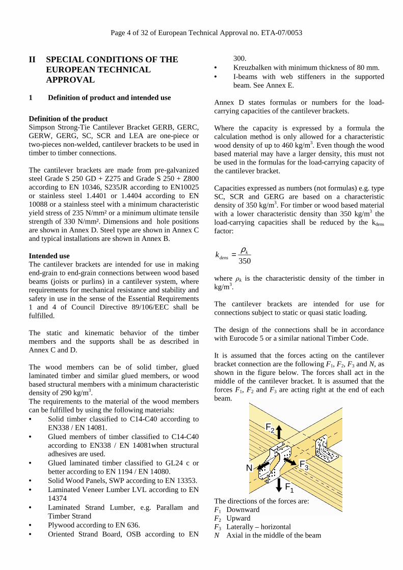
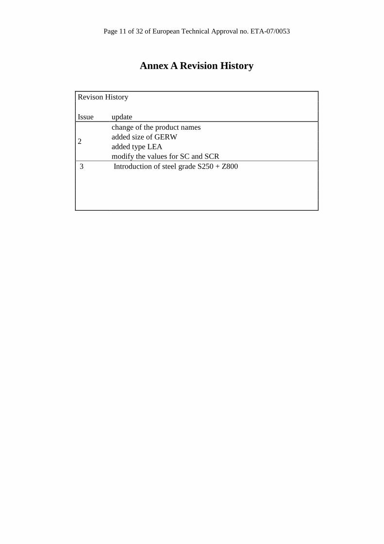
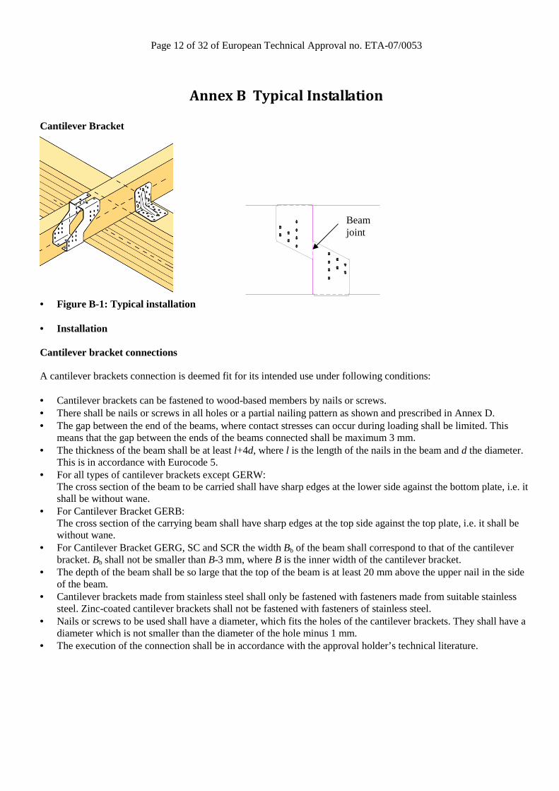
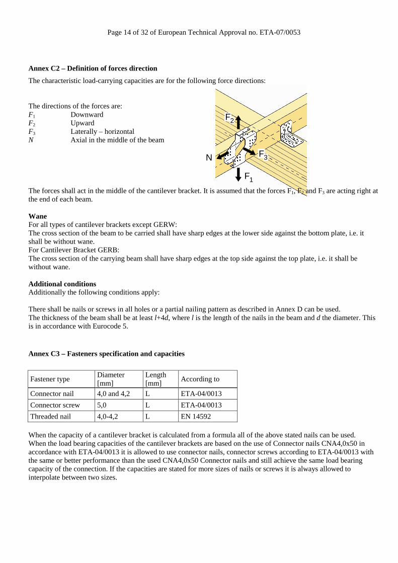
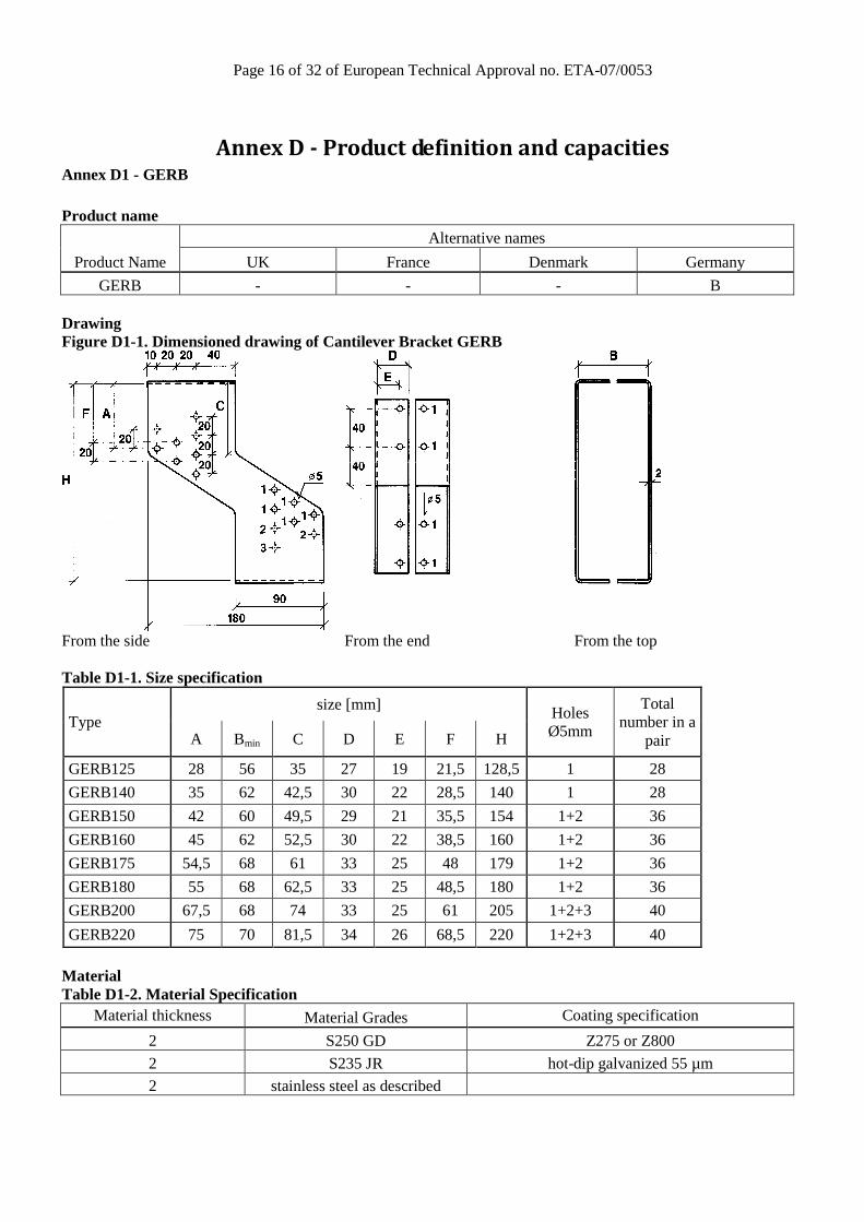
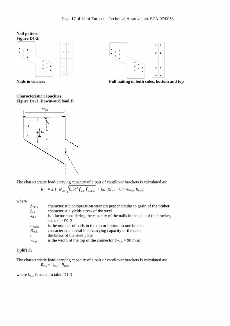
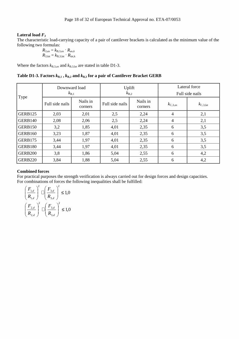
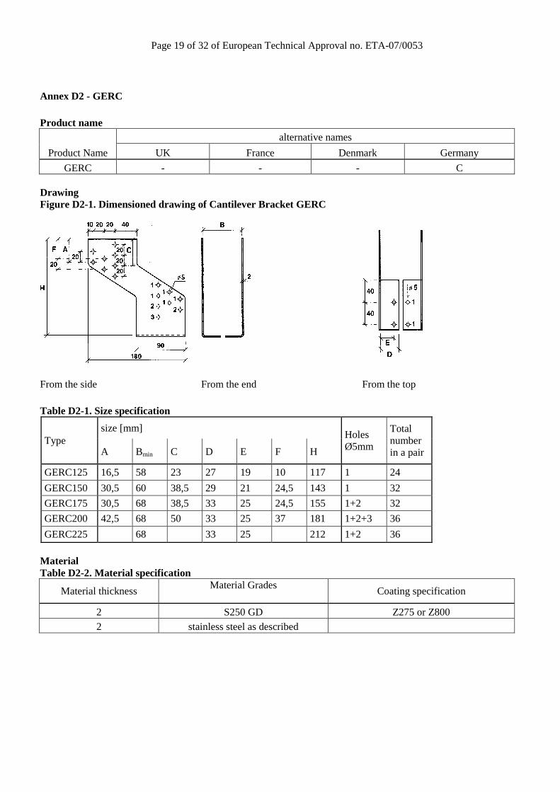
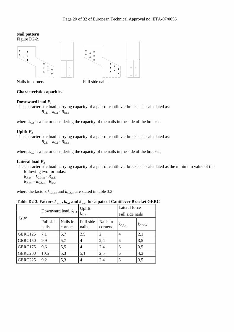
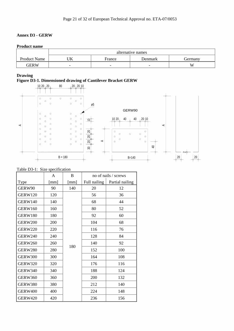
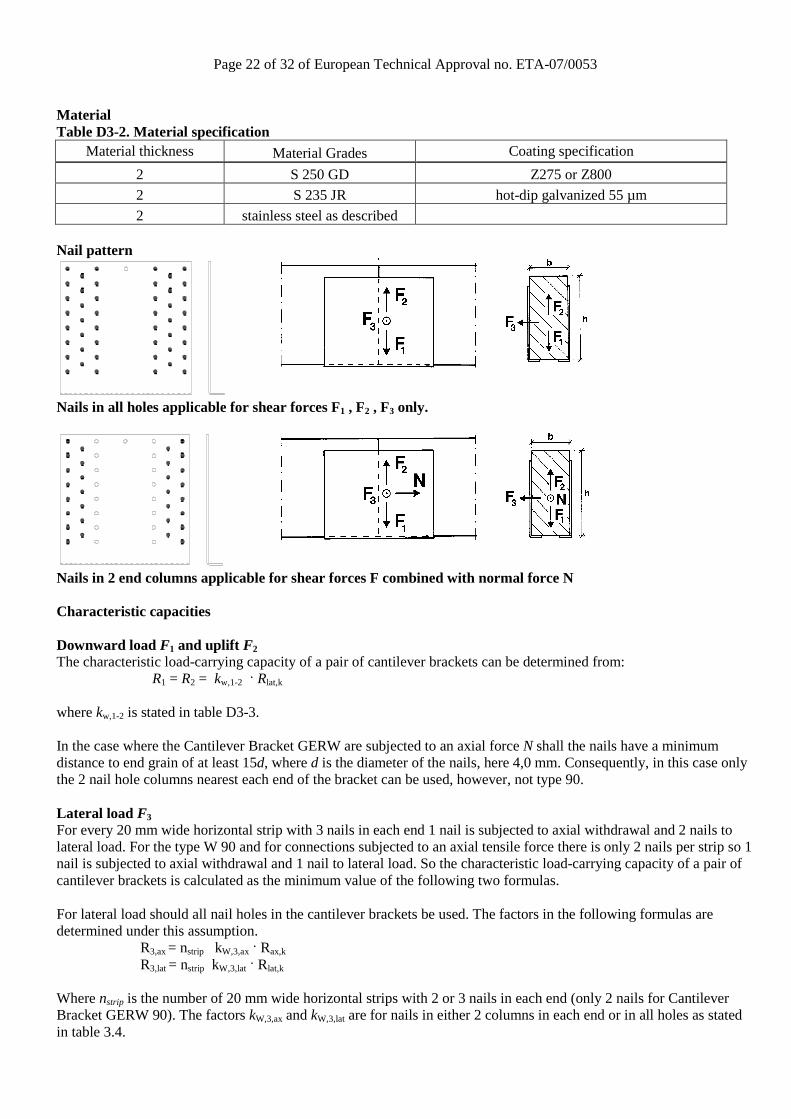
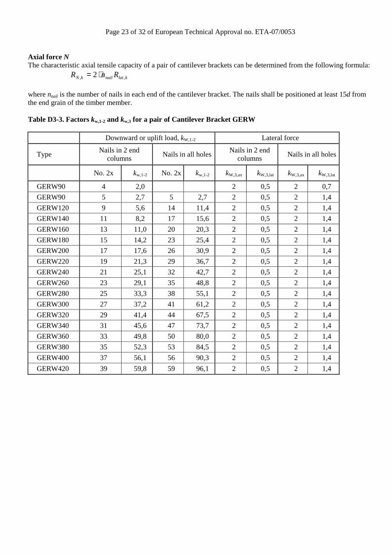
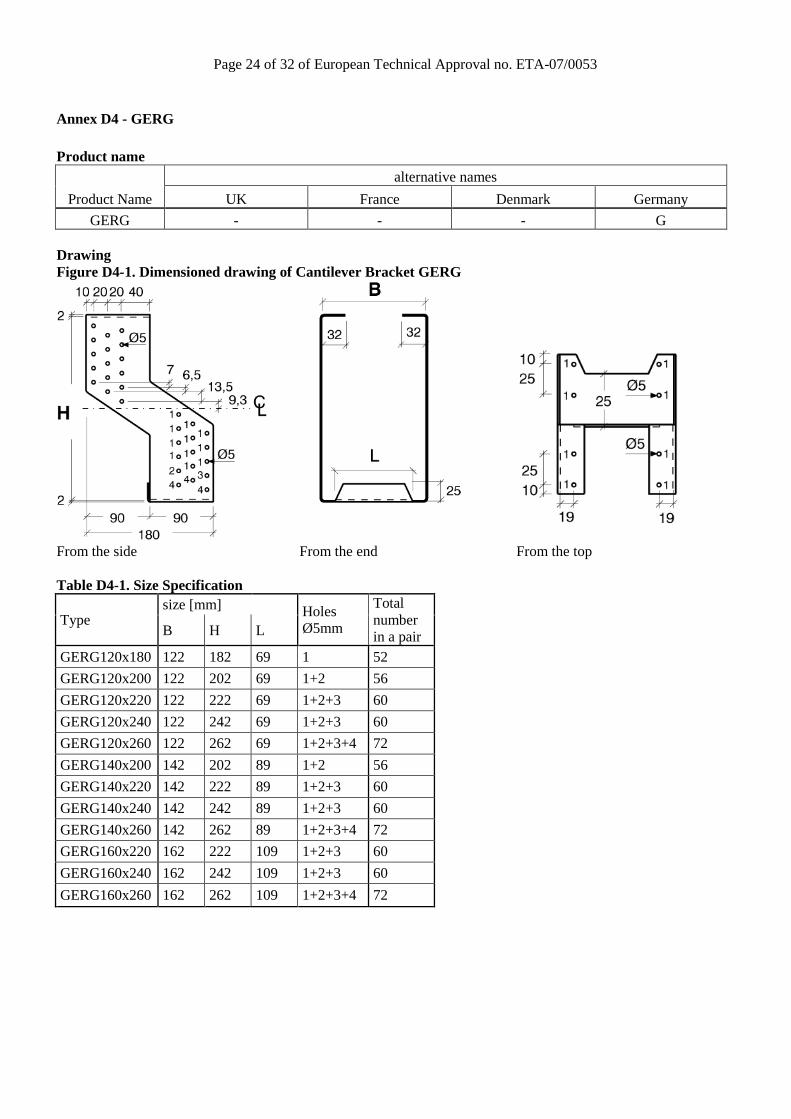
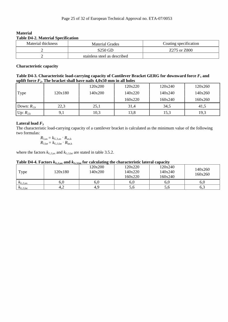
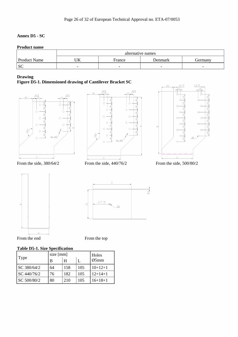
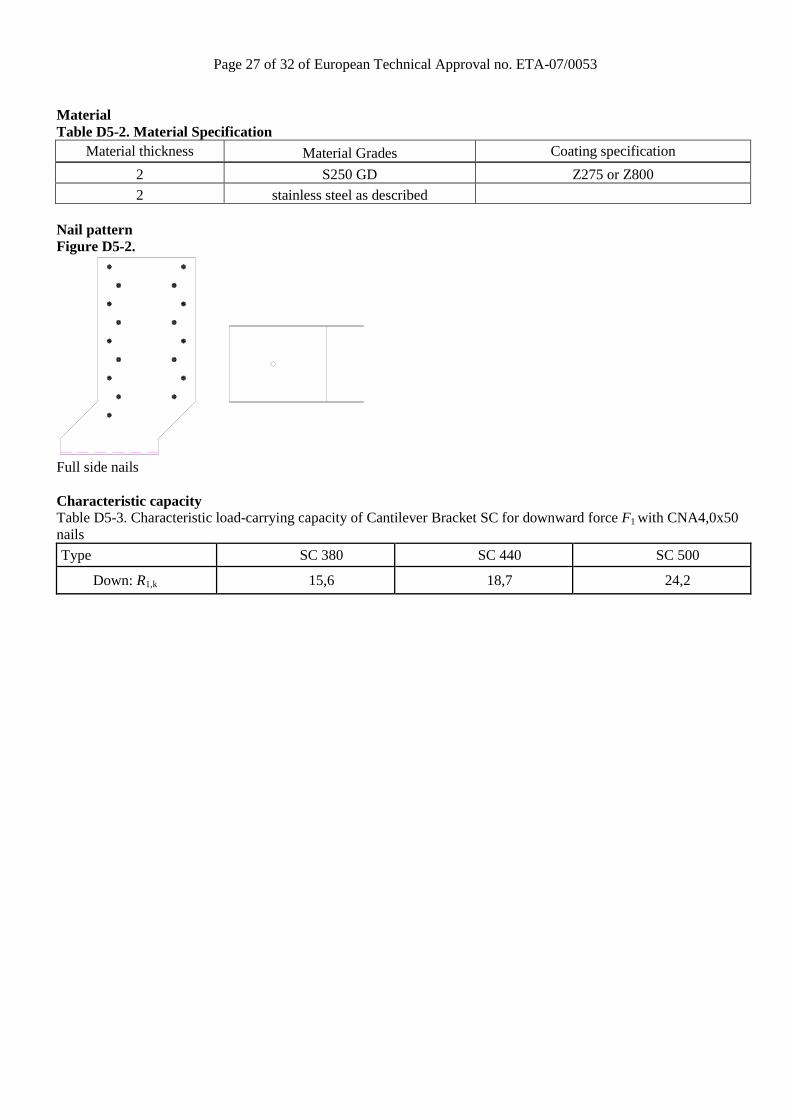
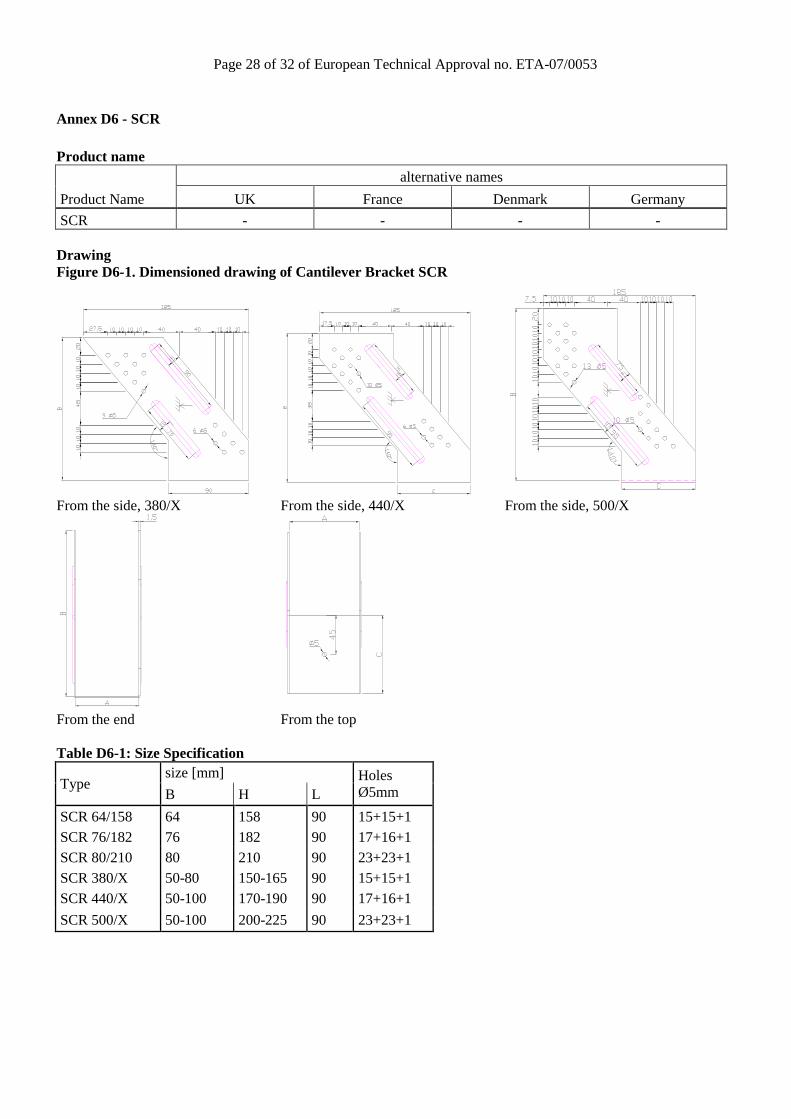
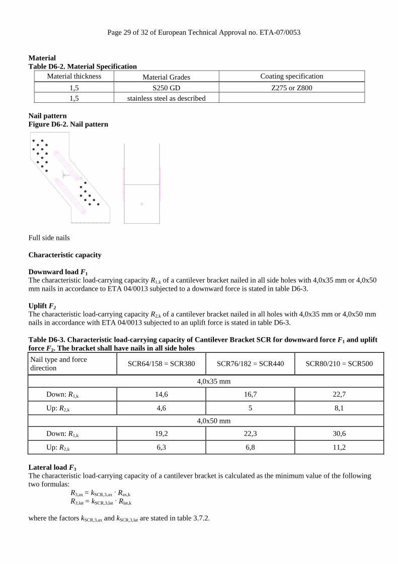
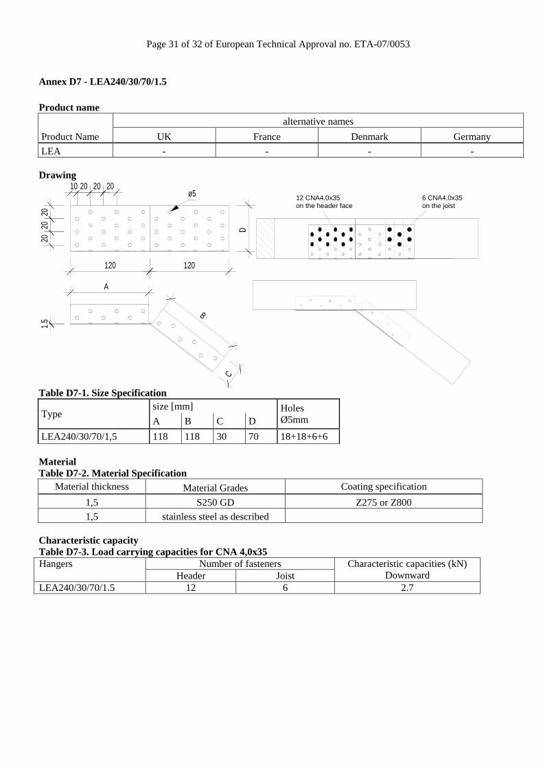
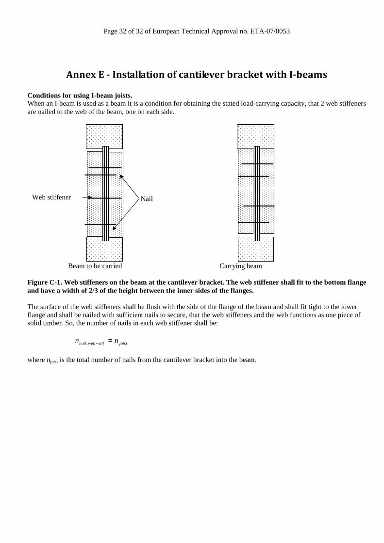