european standard norme europeenne europaische norm...
TRANSCRIPT
""" -. -.-,"",-, '-""'''~-;Oo'- ~-=~ ::E ~
EUROPEAN STANDARDNORME EUROPEENNEEUROPAISCHE NORM
EN 10308
November 2001
ICS 77.040.20; 77.140.6Q.
English version
Non-destructive testing
Ultrasonic testing of $teel bars
Essais non destructifs - Contrale parultrasons des barres en acier
Zerst6rungsfreie ~rUfung - Ultra-schaliprUfung von Staben aus Stahl
This European Standard was approved by CEN on 2001-09-30.CEN members are bound to comply with the CEN/CENELEC Internal Regulationswhich stipulate the conditions for giving this European Standard the status of anational standard without any alteration.Up-to-date lists and bibliographical references concerning such national stand-ards may be obtained on application to the Management Centre or to anyCEN member.
The European Standards exist in three official versions (English, French, German).A version in any other language made by translation under the responsibility of aCEN member into its own language and notified to the Management Centre hasthe same status as the official versions. .
CEN members are the national standards bodies of Austria, Belgium, the CzechRepublic, Denmark, Finland, France, Germany, Greece, Iceland, Ireland, Italy,Luxembourg, the Netherlands, Norway, Portugal, Spain, Sweden, Switzerland,and the United Kingdom.
;;"'"00'"'?'":t:~Q
CENEuropean Committee for Standardization
Comite Europeen de NormalisationEuropaisches Komitee fUrNormung
:0.
"0«:'-::::.;,::
;;;.s'"'"'"I,)
(~
Management Centre: rue de Stassart 36, B-1050 Brussels
@ 2001. CEN - All rights of exploitation in any form and by any meansreserved worldwide for CEN national members.
Ref. No. EN 10308 : 2001 E
<:Q@
.- --50J7<fJQOQ~~,
<--U
Page 2EN 10308 : 2001
Contents
Foreword Page'"'''''''''''''''''''''''' 2
1
2
3
4
5
6
7
88.18.28.38.48.5
9
,..'""'"00.Q~;;;:x:?r)><i'"§E0~...:2
.j:;
.s
~~Q
@
Scope. m 3
Norm ative refere n ces , 3
Terms and defin itions " ." 3
Ite m s for agree me nts 0""""" 00"'" 00"" '"''''''''0''''''''''''''''' ..oo , 0""""'''''''''''''''''''''''' 4
Principie 0" 4
Proced ure oo , "'''''''''''''''''''''''''''''''''''''''''''''''''''''''''''''OO'''''''''''''''''''''''''''''''''''''''''' 5
10
11
Personnel qual ifi cation ,. 5
UItraso nIc test eq uIpment ", , 0"'" 6In stru me nt ., "0"'"'''''''''''''''''''''''''''''''''''''''''''''''''''''''''' 6Probe o.0"""""" 0"'" 6Cali bratio n blocks """"'''''''''''''''' , : 6Refere nee bl oe ks m : 6Co uPIant 0""""""'"'''''''''''''''''''' on 6
Routine cal ibration and checking ,.. 7
Stage of manufacture m 7
Surface cond ition ".. , ... """""" 7
Sen siti vity setti n9 0""""""""'"'''''''''''''''''''''''''''''''''''''''''''''''''''''''''''''''''''''''''''''''''''''''''' 7
Sca nn in9 , ,. .m 7Gene ra I 7Grid scan ning cove rage 7Complete scan nin 9 coverage. ..,... .,.. 7Scan n in 9 speed 8
Class ificati on ,..n.. , 8Class ificatio n of ind icati on s ..m """""""'''''''''''''''''''"""""", 8Classification of discontinu ities... .., "''''''''''''OO'''''' " '"'''''''' 10
12
1313.113.213.313.4
1414.114.2
Recording level and acceptance criteria 11
S izing 13
Test report oo , 13
Annex A (informative)List of equivalent terms in several European languages 14
Bibliography.. n 14
15
16
17
Foreword
This European Standard has been prepared by Technical Committee ECISSfTC 2 .Steel - Physico-chemicalandnon-destructivetesting", the secretariat of which is held by AFNOR.
This European Standard shall be given the status of a national standard, either by publication of an identical text orby endorsement, at the latest by May 2002, and conflictingnational standards shall be withdrawn at the latest byMay2002.AnnexA is informative.
This standard includes a Bibliography.
According to the CEN/CENELEC Internal Regulations, the national standards organizations of the followingcountries are bound to implement this European Standard: Austria, Belgium, Czech Republic, Denmark, Finland,France, Germany, Greece, Iceland, Ireland, Italy, Luxembourg, Netherlands, Norway, Portugal, Spain, Sweden,Switzerlandand the UnitedKingdom.

9
r-"
~'"".>;""'"?c:"
;;:;,,;'"'""E"<:'-'2
":2U~WQ<:i5(2)
""" """""""' ,-=... .;""=-c-=,,,,~=-=c_~~_c~= .,......
Page 3EN 10308: 2001
1 Scope
This European Standard describes the techniques to be used for the manual, pulse-echo, ultrasonic testing of steelbars of diameter or equivalent thickness less or equal to 400 mm or equivalent section. Mechanised,semi-automatic or automatic techniques may be used but should be agreed between the purchaser and thesupplier.
2 Normative references
This European Standard incorporates by dated or undated reference, provisions from other publications. Thesenormative references are cited at the appropriate places in the text, and the publications are listed hereafter. Fordated references, subsequent amendments to or revisions of any of these publications apply to this EuropeanStandard only when incorporated in it by amendment or revision. For undated references the latest edition of thepublication referred to applies (including amendments).
EN 473, Non destructive testing - Qualification and certification of NDT personnel- General principles.
EN 583-2, Non-destructive testing - Ultrasonic examination - Part 2: Sensitivity and.range setting.
EN 583-5, Non-destructive testing - Ultrasonic examination - Part 5: Characterization and sizing of discontinuities.
EN 1330-4, Non destructive testing - Terminology - Part 4: Terms used in ultrasonic testing..
EN 12223, Non-destructive testing - Ultrasonic examination - Specification for calibration block n01.
EN 12668-1, Non-destructive testing - Characterization and verification of ultrasonic examination equipment - Part1: Instruments.
EN 12668-2, Non-destructive testing - Characterization and verification of ultrasonic examination equipment - Part2: Probes.
EN 12668-3, Non-destructive testing - Characterization and verification of ultrasonic examination equipment - Part3: Combined equipment.
3 Terms and definitions
Definitions for general terms of non-destructive testing can be found in other European Standards, e.g. EN 1330-1and EN 1330-2. For the purposes of this European Standard, the following terms and definitions given in EN 1330-4 apply, together with the following.
3.1manual testingtesting by an operator applying an ultrasonic probe, or probes, to the product surface, manually executing theappropriate scanning pattern on the product surface and assessing ultrasonic signal indications on the electronicequipment screen either by direct viewing or by built-in signal amplitude alarm devices
3.2automatic and semi-automatic testingtesting using a mechanised means of applying the ultrasonic probe or probes to, and executing the appropriatescanning pattern on the flat product surface, together with ultrasonic signal indication evaluation by electronicmeans
NOTE Such testing can be either fully automatic with no operator involvement, or semi-automatic when the operatorperforms basic equipment operation functions.
A list of equivalent terms in several European languages in given in annex A.

,--
y
.-; -.- -~. ;z::'-~-; .v... -~" ..-"~---.-.--- :z:
Page 4EN 10308 : 2001
4 Items for agreements
The following aspects concerning ultrasonic testing shall be agreed between the purchaser and supplier at the timeof the enquiry or order:
a) the manufacturing stage(s) at which ultrasonic testing shall be performed (see clause 10);
b) the volume(s) to be tested and whether grid scanning coverage or complete scanning coverage is required(see clause 13);
c) the Quality Class required, or the Quality Classes and the zones to which they apply (see clause 15);
d) the applicable evaluation level and acceptance criteria if different from those detailed in Tables 2 and 3;
e) whether any special scanning coverage, equipment or couplant is required in addition to that detailed inclauses 8 and 13;
f) the scanning technique to be used if not manual;
g) the sizing techniques to be used for extended discontinuities (see clause 16);
h) the technique(s) to be used for setting sensitivity (see clause 12);
i) whether the test is to be conducted in the presence of the purchaser or his representative; .,
j) whether a written procedure shall be submitted for approval by the purchaser (see clause 6).
5 Principle
The method used is based on the reflection of ultrasonic waves (generally longitudinal), the direction of which isapproximately perpendicular to the surface of the product. The examination consists of:
a) locating and evaluation of discontinuity by comparing the amplitude of the discontinuity echo with theamplitude of the echo of a flat-bottomed hole of a given diameter and located at the same depth as thediscontinuity.
NOTE Only those discontinuities giving an echo in amplitude equal to or greater than that obtained with the reference flat-bottomed hole are taken into consideration.
b) determining the area of the discontinuity according to the - 6 dB beam width technique.
If areas with particular permeability are located, the testing conditions shall be adjusted in order to test these areaswith the required sensitivity level.
The examination is carried out during the first ultrasonic scan (first back wall echo) for all the product thicknesses ordiameter and from one side only.
'"""
~a;;;;oi!?:ss"'<c
,,'-"'"'"J::\)~'"a:<:Q@

.?"
,>;aa
'"'"<::'":::<:15:>:;;;
r-"'-S"'ill'""~r!i
""" ---"'"'-' ..~ ,~-,'" :z:
Page 5EN 10308 : 2001
6 Procedure
The inspection is normally carried out in the place of production or on the premises of the supplier. If specified onthe order, the inspection may take place in the presence of the purchaser or his representative 1).
Ultrasonic testing shall be performed in accordance with a written procedure. Where specified in the enquiry ororder, the written procedure shall be submitted to the purchaser for approval prior to testing.
This written procedure shall be in the form of:
a) a product specification or;
b) a procedure written specifically for the application or;
c) this European Standard may be used if it is accompanied by examination details specific to the application.
The procedure shall contain the following details as a minimum requirement
a) description of the item to be examined;
b) reference documents;
c) qualification and certification of examination personnel;
d) stage of manufacture at which the examination is carried out;
e) examination zones specified in terms of the applicable Quality Classes;
f)
g)
any special preparation of scanning surfaces, if applicable;
couplant;
h) description of examination equipment;
i) calibration;
j)
k)
scanning plan;
description and sequence of examination operations;
I) recording level;
m) characterisation of discontinuities;
n)
0)
acceptance criteria;
examination report.
7 Personnel qualification
It is assumed that ultrasonic testing is performed by qualified and capable personnel. In order to prove thisqualification, it is recommended to certify the personnel in accordance with EN 473 or equivalent.
" In this case, all steps should be taken to ensure that the production process is not disturbed.
~ ~............
..

- -.-= :II:-..' " ._.
Page 6EN 10308 : 2001
8 Ultrasonic test equipment
8.1 Instrument
Instrument for manual testing shall feature A-scan presentation and shall comply with the requirements ofEN 12668-1.
8.2 Probe
8.2.1 General
Single transducer probes and double transducer probes shall conform to the requirements of EN 12668-2.
Additionally, other types of probes may be used. Such supplementary probes need not to comply with EN 12668-2requirements. .
8.2.2 Contouring
Probes shall be contoured when required according to EN 583-2.
8.2.3 Nominal frequency~
Probes shall have a nominal frequency in the range from 1 MHz to 6 MHz...
8.2.4 Type of probes
The greatest transducer dimension shall be in the range from 9 mm to 25 mm, unless otherwise agreed. Doubletransducer probes can be used for bars with sizes up to 150 mm diameters or thickness.
Single transducer probes shall be used for bars with diameter or thickness greater than 60 mm.
8.3 Calibration blocks
Calibration blocks shall conform to the requirements detailed in EN 12223.
8.4 Reference blocks
References blocks shall be made from a material having similar acoustic properties to the product to be examined.The surface condition of the reference block shall be representative of the surface condition of the bars to beexamined. Unless otherwise specified the reference block shall contain at least three reflectors covering the entiredepth range under examination.
The form of the reference block will depend upon the application.
'"'>""<><>~'"J::~Q.':>
The bottom of the holes shall be as flat as practicable, parallel to the ultrasound entry surface and free from pits orscore marks that significantly degrade its ultrasonic reflectivity. The tolerance on the diameter of the flat-bottomedhole or width of recess shall be :!: 5 %.
8.5 Couplant
The couplant used shall be appropriate to the application. The same type of couplant shall be used for calibration,setting sensitivity, scanning and evaluation of discontinuities.
"'. After examination, couplant shall be removed if its presence could adversely affect later manufacturing or.c inspection operations or the integrity of the component<> .
<1:
~ NOTE Water is normally used but other coupling media may be used at the discretion of the supplier.i5if>oSif>ill'"
*

'':;'"..,'"'"is<:J!.~a:;:;<;;?"
2;.<:'-:<:
'".s'"'".c:u
.~
"
-Page 7
EN 10308 : 2001
9 Routine calibration and checking
The combined equipment (instrument and probes) shall be calibrated and checked in accordance with therequirements detailed in EN 12668-3.
10 Stage of manufacture
Ultrasonic testing shall be performed after the final quality heat treatment unless otherwise agreed at the time ofenquiry and order.
11 Surface condition
Scanning surfaces shall be free from paint, non-adhering scale, dry couplant, surface irregularities or any othersubstance which could reduce coupling efficiency, hinder the free movement of the probe or cause errors ininterpretation. The surface condition shall be considered acceptable providing the specified quality class can beachieved.
12 Sensitivity setting
Sensitivity shall be sufficient to ensure the detection of the smallest discontinuities required by therecording/evaluation levels (see Tables 2 and 3).
One of the following techniques shall be used to establish sensitivity for scanning with a particular probe. Theprocedure to be used in each case shall be as detailed in EN 583-5.
a) Distance Amplitude Curve (DAC) technique, based upon the use of flat-bottomed holes (FBH);
b) distance gain size (DGS) technique.
13 Scanning
13.1 General
Manual scanning shall be performed using the manual contact pulse-echo technique.
The minimum scanning coverage required is dictated by the type of bars and whether grid scanning coverage orcomplete scanning coverage has been specified in the enquiry or order.
Table 1 classifies two types of bars according to their shapes and specifies the requirements for normal scanningcoverage for bars.
13.2 Grid scanning coverage
Grid scanning shall be performed with the probe or probes traversed along the grid lines defined in Table 1.
Where recordable indications are revealed by grid scanning, additional scanning shall be performed to determinethe extent of the indications.
13.3 Complete scanning coverage
Complete scanning coverage shall be performed over the surfaces specified in Table 1, by overlapping consecutiveprobe traverses by at least 10 % of the transducer diameter.

Page 8EN 10308 : 2001
13.4 Scanning speed
Manual scanning speed shall not exceed 150 mm/s.
Type
Table 1 - Scanning coverage with normal probes
Complete scanning a b
1a
1b
1c
~ -
Grid scanning a b
Diameter, D orthickness, t
Scan lines C
mm
D ~ 200
200 < D ~ 400
2 at 900
3 at 600 or 1200
Scan completely around atleast 1800 of cylind ricalsurface
t ~ 150 1 line on 2 faces
3 lines on 2 faces d
Scan completely on twoperpendicular surfaces
150 < t ~ 400
t ~ 150
150 < t ~ 400
1 line on 2 faces
I
Scan completely on at
1 I.
I f least half adjacent facesme on at east hal
number of faces
a Additional scanning may be carried out if specified in the enquiry or order.
b A scanning may be carried out following a sinusoidal pattern or zigzag line over the complete length of the area givingthe same degree of control.
C For type 1a or 1b, if the presence of a bore prevents the opposite surface being reached, the number of scan lineshall be doubled symmetrically.
dThe grid line separation shall be equal to the part thickness up to a maximum of 200 mm.
14 Classification
-c"'"'""'"?;;:x:
14.1 Classificationof indications
Indications shall be classified according to their echodynamic patterns, as follow:
a) Pattern 1
As the probe is moved, the A-scan display shows a single sharp indication rising smoothly in amplitude to amaximum and then falling smoothly to zero (see Figure 1)."'"<:"
§ This pattern corresponds to discontinuity dimensions smaller than or equal to the - 6 dB beam profile, such as the:: . echodynamic pattern obtained from the side-drilled holes used to plot the beam profile.2
.C
~:;:is<f)

""
..""
?;;J::~Q
;;,;'"
§~:iF,.
;;.s'"".t::U~0;
Q=<:Qq
1
2
Key
1 Amplitude2 Range3 Probeposition
A-scan presentation (at typical probe position)
Page 9EN 10308 : 2001
1
3
Echodynamic pattern (variation in signal amplitudeas probe is moved)
Figure 1 - Pattern 1 A-scan presentation and echo envelope presentation
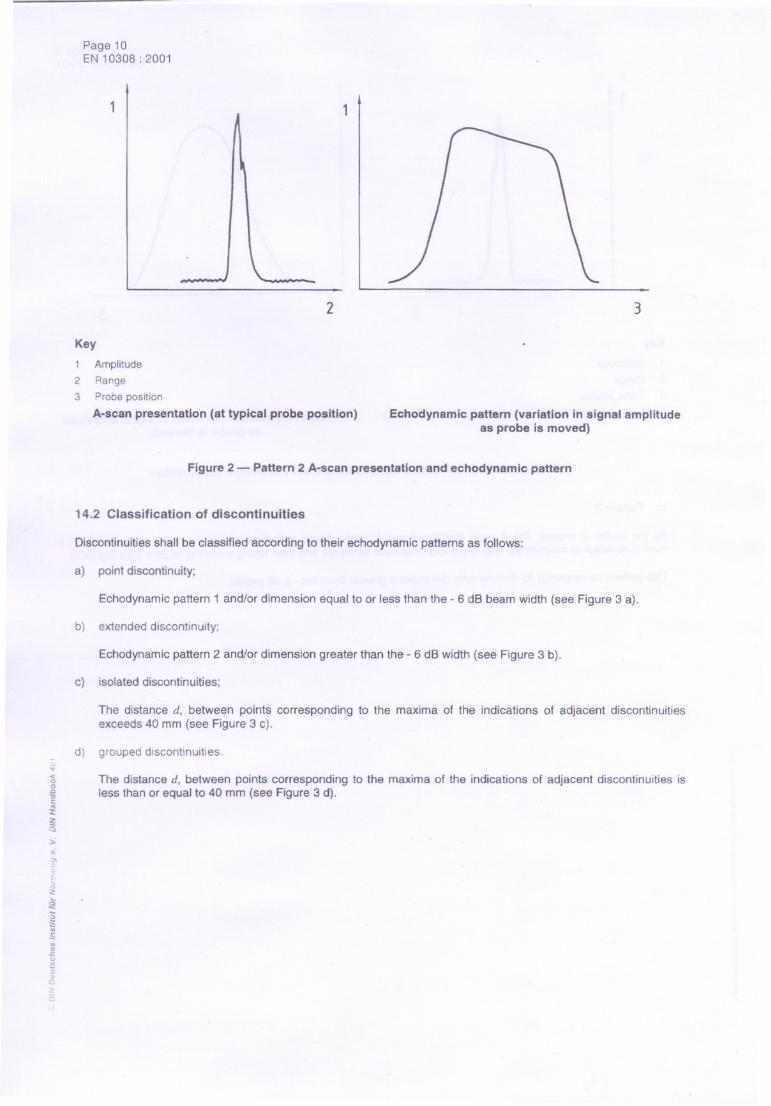
b) Pattern 2
As the probe is moved, the A-scan display shows a single sharp indication rising smoothly in amplitude to amaximum which is maintained with or without amplitude variation, and then falling smoothly to zero (see Figure 2),
This pattern corresponds to discontinuity dimensions greater than the - 6 dB profile.
Page 10EN 10308: 2001
2
Key
1
2
3
Amplitude
Range
Probe position
A-scan presentation (at typical probe position)
1
3
Echodynamic pattern (variation in signal amplitudeas probe is moved)
Figure 2 - Pattern 2 A-scan presentation and echodynamic pattern
14.2 Classification of discontinuities
Discontinuities shall be classified according to their echodynamic patterns as follows:
a) point discontinuity;
b) extended discontinuity;
Echodynamic pattern 1 and/or dimension equal to or less than the - 6 dB beam width (see Figure 3 a).
Echodynamic pattern 2 and/or dimension greater than the - 6 dB width (see Figure 3 b).
c) isolated discontinuities;
The distance d, between points corresponding to the maxima of the indications of adjacent discontinuitiesexceeds 40 mm (see Figure 3 c).
d) grouped discontinuities."""'"00~t:'":c:1;Q
::>.,;
r"~...'2{§VISVI'".c:I.J~(~
The distance d, between points corresponding to the maxima of the indications of adjacent discontinuities isless than or equal to 40 mm (see Figure 3 d).
,.~

Page 11 .EN 10308: 2001
~
C)
11
a) Point discontinuity (L S Dp) b) Extended discontinuity (L > Dp)
D
d
1
d
c) Isolated points discontinuities (L < Dp. d> 40 mm) d) Grouped point discontinuities (L < Dp. d S 40 mm)
Key
Conventionaloutline of - 6 dB discontinuity
Symbols used
Dp Width of beam at depth of discontinuityd Distance between two discontinuities
L Conventional length of -6 dB discontinuity~'"'>-'<00'"'?'":J:
Figure 3 - Classification of discontinuities
<~('S ,5 Recording level and acceptance criteria:>'"OJ<:::::t:;0
:<:'-:i2
Several Quality Classes may be applied to bars. The applicable Quality Class(es) shall be agreed between thepurchaser and supplier. Tables 2 and 3 details recording level and acceptance criteria, which shall be applied tothree Quality classes for normal probes.
g'.
q;Q<:25<0

Page 12EN 10308: 2001
Table 2 - Quality classes, recording level and acceptance criteria for ferritic and martensitic steel bars
Table 3 - Quality class, recording level and acceptance criteria for austenitic and austenoferritic steel bars
-'""Si~iii:c~C)::>.;'"'":::~:::~..
.r..£'"'"-<:"~0;C)<:0,,;
Parameter Quality Class
1 2 3 4
Recording level
Equivalent flat bottomed holes (EFBH) deq mm a>6 >5 >3 >2
Ratio R for rapid backwall echo reduction b c $0,1 $0,3 . 0,5 $0,5
Acceptance criteria
EFBH (Isolated point type discontinuities) deq mm a$12 $8 $5 $3
EFBH (Extended or grouped point type discontinuities) deq mm a$8 $5 $3 $2
adeq =Equivalent diameter of flat bottomed hole.
b FR=
Fa,n
where
n = 1 for 1 60 mm;
n = 2 for 1< 60 mm;
Fn = amplitude (screen height) of the nth reduced backwall echo;
Fo. n =amplitude (screen height) of the nth backwallecho in the nearest discontinuity-freearea at the same range as Fn'
cIf the reduction in backwall echo exceeds the recording level, this shall be further investigated. Ratio R applies only to rapid
reduction of backwall echo caused by the presence of a discontinuity.
Bars thicknessRecording level deq
a Acceptance criteria for isolated Acceptance criteria for
discontinuities deq a extended and grouped
discontinuities deq a
mm mm mm mm
Quality class 1
1$ 75 >5 $8 $5
75 < I <;250 >8 $ 11 $8
250 < 1$ 400 > 14 $19 $14
Quality class 2
1$ 75 >3 $5 $3
75 < I $ 250 >5 <;8 $5
250<1$400 >8 $ 11 $8
Quality class 3
1<;75 >2 $3 <;2
75 < 1<;250 >3 $5 $3
250 < 1$ 400 >5 $8 $5
a"eq= Equivalentdiameterof flat-bottomedhole.
c"~i:.<:Q:::;'"'""§"<:'-
'"())""u.'2""Q<:25@
.'._~". ~~' "-'= -~,c -'" --~.~ =z-~.
Page 13EN 10308 : 2001
16 Sizing
Where the extent of a discontinuity is required to be evaluated, one or more of the following techniques, as agreedbetween the purchaser and the supplier, shall be used. These techniques shall be carried out in accordance withthe requirements detailed in EN 583-5:
17 Test report
The test report shall include the following information as a minimum requirement:
a) name of supplier;
b) order number;
c) identification of product(s) under examination;
d) scope of examination: examination zones and applicable Quality Classes;
e) stage of manufacture at which ultrasonic testing was performed;
f) surface condition;
g) equipment used (instrument, probes, calibration and reference blocks);
h) technique(s) used to set sensitivity;
i) reference to this standard or reference to the written procedure used (where applicable);
j) results of examination: location, classification of all discontinuities exceeding the appropriate recording level;
k) details of any restrictions to the scanning coverage;
I) date of examination;
m) name, qualification and signature of operator.
a) - 6 dB-drop technique;
b) 20 dB-drop-technique;
c) maximum amplitude technique.