european organisation for technical approvals dec05.pdf · etag 003 edition december 1998 guideline...
TRANSCRIPT

ETAG 003Edition December 1998
GUIDELINE FOR EUROPEAN TECHNICAL APPROVAL
for
INTERNAL PARTITION KITSFOR USE AS
NON-LOADBEARING WALLS
Amended December 2005
EOTAKunstlaan 40, Avenue des Arts
B-1040 Brussels
European Organisation for Technical ApprovalsEuropäische Organisation für Technische ZulassungenOrganisation Européenne pour l’Agrément Technique

Page 2ETAG 003
Table of ContentsFOREWORD................................................................................................................................................. 6
Background of the ETA Guideline.......................................................................................................... 6
Section One: INTRODUCTION.................................................................................................................... 9
1 PRELIMINARIES.................................................................................................................................... 91.1 Legal basis................................................................................................................................... 91.2 Status of ETA guidelines ............................................................................................................. 9
2 SCOPE................................................................................................................................................. 102.1 Scope......................................................................................................................................... 102.2 Use categories, product families, kits........................................................................................ 102.3 Assumptions .............................................................................................................................. 11
3 TERMINOLOGY................................................................................................................................... 133.1 Common terminology and abbreviations ................................................................................... 133.2 Specific terminology................................................................................................................... 13
Section Two: GUIDANCE FOR THE ASSESSMENT OF THE FITNESS FOR USE................................. 15
4 REQUIREMENTS ............................................................................................................................... 174.1 Mechanical resistance and stability ........................................................................................... 184.2 Safety in case of fire .................................................................................................................. 19
4.2.1 Reaction to fire............................................................................................................ 194.2.2 Fire resistance ............................................................................................................ 19
4.3 Hygiene, health and the environment ........................................................................................ 194.3.1 Release of formaldehyde, asbestos (content), pentachlorophenol and other
dangerous substances ............................................................................................... 204.3.2 Water vapour permeability.......................................................................................... 204.3.3 Water permeability...................................................................................................... 20
4.4 Safety in use .............................................................................................................................. 204.4.1 Resistance to horizontal and eccentric loads ............................................................. 204.4.2 Safety against personal injuries by contact ................................................................ 20
4.5 Protection against noise ............................................................................................................ 214.5.1 Airborne sound insulation ........................................................................................... 214.5.2 Sound absorption........................................................................................................ 21
4.6 Energy economy and heat retention.......................................................................................... 214.6.1 Thermal resistance ..................................................................................................... 214.6.2 Thermal inertia............................................................................................................ 22
4.7 Aspects of durability and serviceability ...................................................................................... 224.7.1 Robustness and rigidity .............................................................................................. 224.7.2 Resistance to deterioration ......................................................................................... 22
4.7.2.1 Physical agents.......................................................................................... 224.7.2.2 Chemical agents........................................................................................ 234.7.2.3 Biological agents........................................................................................ 23
4.7.3 Identification................................................................................................................ 23
5. METHODS OF VERIFICATION........................................................................................................... 245.1 Mechanical resistance and stability ........................................................................................... 265.2 Safety in case of fire .................................................................................................................. 26
5.2.1 Reaction to fire............................................................................................................ 265.2.2 Fire resistance ............................................................................................................ 26

Page 3ETAG 003
5.3 Hygiene, health and the environment ........................................................................................ 265.3.1 Release of formaldehyde, asbestos (content), pentachlorophenol and other
dangerous substances ............................................................................................... 265.3.2 Water vapour permeability .......................................................................................... 275.3.3 Water permeability ...................................................................................................... 28
5.4 Safety in use .............................................................................................................................. 285.4.1 Resistance to horizontal and eccentric loads.............................................................. 28
5.4.1.1 Resistance to structural damage from soft body impact load - 50 kgbag ............................................................................................................. 28
5.4.1.2 Resistance to structural damage from hard body impact load - 1 kgsteel ball ..................................................................................................... 28
5.4.1.3 Resistance to structural damage from eccentric vertical load ................... 285.4.1.3 Resistance to structural damage from eccentric vertical load ................... 285.4.1.4 Resistance to horizontal linear static load.................................................. 28
5.4.2 Safety against personal injuries by contact ................................................................. 295.5 Protection against noise............................................................................................................. 29
5.5.1 Airborne sound insulation............................................................................................ 295.5.2 Sound absorption ........................................................................................................ 29
5.6 Energy economy and heat retention .......................................................................................... 295.6.1 Thermal resistance ..................................................................................................... 295.6.2 Thermal inertia ............................................................................................................ 30
5.7 Aspects of durability and serviceability....................................................................................... 305.7.1 Robustness and rigidity............................................................................................... 30
5.7.1.1 Resistance to functional failure from soft body impact load - 50 kgbag ............................................................................................................. 30
5.7.1.2 Resistance to functional failure from hard body impact load - 0.5 kgsteel ball ..................................................................................................... 30
5.7.1.3 Resistance to functional failure from eccentric vertical load ...................... 315.7.1.4 Resistance to functional failure from point loads parallel or
perpendicular to the surface....................................................................... 315.7.1.5 Rigidity of partitions to be used as a substrate for ceramic tiling ............... 31
5.7.2 Protection against deterioration .................................................................................. 315.7.2.1 Physical agents .......................................................................................... 315.7.2.2 Chemical agents ........................................................................................ 325.7.2.3 Biological agents ........................................................................................ 32
5.7.3 Identification ................................................................................................................ 32
6. ASSESSING AND JUDGINGthe fitness for use of products for an intended use............................................................................... 346.1 Mechanical resistance and stability............................................................................................ 356.2 Safety in case of fire................................................................................................................... 35
6.2.1 Reaction to fire ............................................................................................................ 356.2.2 Fire resistance............................................................................................................. 35
6.3 Hygiene, health and the environment ........................................................................................ 366.3.1 Release of formaldehyde, asbestos (content), pentachlorophenol and other
dangerous substances ............................................................................................... 366.3.2 Water vapour permeability .......................................................................................... 366.3.3 Water permeability ...................................................................................................... 36
6.4 Safety in use .............................................................................................................................. 366.4.1 Resistance to horizontal and eccentric loads.............................................................. 36
6.4.1.1 Resistance to structural damage from soft body impact load - 50 kgbag ............................................................................................................. 39
6.4.1.2 Resistance to structural damage from hard body impact load - 1 kgsteel ball ..................................................................................................... 39
6.4.1.3 Resistance to structural damage from eccentric vertical load ................... 396.4.1.4 Resistance to horizontal linear static load.................................................. 40
6.4.2 Safety against personal injuries by contact ................................................................. 406.5 Protection against Noise ............................................................................................................ 40
6.5.1 Airborne sound insulation............................................................................................ 406.5.2 Sound absorption ........................................................................................................ 40
6.6 Energy economy and heat retention .......................................................................................... 416.6.1 Thermal resistance ..................................................................................................... 41

Page 4ETAG 003
6.6.2 Thermal inertia ............................................................................................................ 416.7 Aspects of durability and serviceability....................................................................................... 41
6.7.1 Robustness and rigidity............................................................................................... 416.7.1.1 Resistance to functional failure from soft body impact load - 50 kg
bag ............................................................................................................. 426.7.1.2 Resistance to functional failure from hard body impact load - 0.5 kg
steel ball ..................................................................................................... 436.7.1.3 Resistance to functional failure from eccentric vertical load ...................... 436.7.1.4 Resistance to functional failure from point load parallel or
perpendicular to surface............................................................................. 446.7.1.5 Rigidity of partitions to be used as a substrate for ceramic tiling ............... 44
6.7.2 Resistance to deterioration ......................................................................................... 446.7.2.1 Physical agents .......................................................................................... 456.7.2.2 Chemical agents ........................................................................................ 456.7.2.3 Biological agents ........................................................................................ 45
6.8 Identification of the product ........................................................................................................ 45
7. ASSUMPTIONS AND RECOMMENDATIONSunder which the fitness for use of the products is assessed ................................................................ 467.1 Design and execution of works .................................................................................................. 467.2 Maintenance and repair ............................................................................................................. 47
Section Three: ATTESTATION OF CONFORMITY (AC)........................................................................... 48
8 EVALUATION OF CONFORMITY........................................................................................................ 488.1 EC Decision ............................................................................................................................... 488.2 Responsibilities .......................................................................................................................... 49
8.2.1 Tasks for the manufacturer......................................................................................... 498.2.1.1 Factory production control.......................................................................... 498.2.1.2 Testing of samples taken at the factory ..................................................... 498.2.1.3 Declaration of Conformity........................................................................... 49
8.2.2 Tasks for the manufacturer or the approved body...................................................... 498.2.2.1 Initial Type Testing ..................................................................................... 49
8.2.3 Tasks for the approved body....................................................................................... 508.2.3.1 Assessment of the factory production control system - initial
inspection and continuous surveillance...................................................... 508.2.3.2 Certification of Conformity.......................................................................... 50
8.3 Documentation........................................................................................................................... 508.4 CE marking and information ...................................................................................................... 51
Section Four: ETA CONTENT ..................................................................................................................... 52
9 THE ETA CONTENT ............................................................................................................................ 529.1 The ETA content ........................................................................................................................ 52
9.1.1 Model ETA .................................................................................................................. 529.1.2 Checklist for the issuing body ..................................................................................... 52
9.2 Additional information................................................................................................................. 53
Annex A ....................................................................................................................................................... 54Common Terminology and Abbreviations.................................................................................................... 54
A.1 Works and products................................................................................................................... 54A.2 Performances............................................................................................................................. 54A.3 ETAG-format.............................................................................................................................. 55A.4 Working life ................................................................................................................................ 55A.5 Conformity.................................................................................................................................. 56A.6 Abbreviations ............................................................................................................................. 57
Annex B ....................................................................................................................................................... 58List of reference documents ........................................................................................................................ 58

Page 5ETAG 003
Annex C ....................................................................................................................................................... 60Internal Partition Kits - Resistance to Impact Loads and Suspended Vertical Loads - General .................. 60
C.1 General ...................................................................................................................................... 60C.2 Partition sample ......................................................................................................................... 60C.3 Conditioning ............................................................................................................................... 61C.4 Sequence of tests ...................................................................................................................... 61
Annex D ....................................................................................................................................................... 62Internal Partition Kits - Resistance to Impact Loads and Suspended Vertical Loads - Test Methods......... 62
D.1 Hard body impact load - 0.5 kg steel ball ...................................................................................62D.2 Hard body impact load - 1 kg steel ball ...................................................................................... 62D.3 Soft body impact load - 50 kg bag.............................................................................................. 62D.4 Eccentric vertical load ................................................................................................................ 64D.5 Horizontal linear static load ........................................................................................................ 64
Annex E ....................................................................................................................................................... 66Internal Partition Kits to be used as a Substrate for Ceramic Tiling ............................................................ 66
E.1 Partition Sample......................................................................................................................... 66E.3 Conditioning ............................................................................................................................... 66E.4 Apparatus................................................................................................................................... 66E.5 Test ............................................................................................................................................ 66
Annex F........................................................................................................................................................ 67Internal Partition Kits - Test Reports ............................................................................................................ 67
F.1 Test report.................................................................................................................................. 67F.2 Summary of test results ............................................................................................................. 67
Annex G ....................................................................................................................................................... 68EN 13823: Reaction to fire tests for building products – Mounting and fixing provision .............................. 69
G.1 Terminology ............................................................................................................................... 69G.2 Mounting and fixing in accordance with EN 13823 .................................................................... 69G.3 Extended application rules ......................................................................................................... 70
Annex H ....................................................................................................................................................... 71Resistance to fire – extended application rules ........................................................................................... 71
Part 1 General requirements for extended application ......................................................................... 71Part 2 Rules for partitions ..................................................................................................................... 74Part 3 Rules for glazed screens............................................................................................................ 82

Page 6ETAG 003
FOREWORD
Background of the ETA Guideline
This Guideline has been drawn up by the EOTA Working Group 05.05/01 - Internal Partition Kits for Useas Non-loadbearing Walls.
The original WG consisted of members from nine EU-countries (Denmark (Convenor), Belgium, Finland,France, Germany, Netherlands, Italy, Portugal and the United Kingdom) and one European industrialorganisation (EuroGypsum representing the European Confederation of Construction ProductsManufacturers). At the last WG meeting the European Federation of Fibre-Cement Manufacturers wasrepresented as well.
The scope of the revision of the Guideline was as follows:
• Updating of references concerning fire including extended application rules and mounting and fixingrules
• Updating of references concerning dangerous substances• Updating of references concerning identification• Updating of Attestation of conformity levels based on the revised mandate• Introduction of additional regulatory requirements from Member States for glazed (non-opaque)
partitions• Amendment of descriptions of test and assessment methods on the basis of experience• Introduction of a horizontal load on partitions acting as barriers in accordance with the
recommendations of EN 1991-1-1• General amendment of the ETAG in accordance with the ETAG Format
Due to the number and magnitude of amendments the working group has considered that it is preferableto elaborate a new revised Guideline rather than to elaborate what would be a very extensive progressfile.
The revision of the Guideline was carried out by representatives from Denmark (Convenor), Austria,Belgium, Finland (by correspondence), France, Germany (by correspondence), Netherlands, Italy andUnited Kingdom.
The scope of the Guideline is the result of a distinction between EOTA- and CEN-involvement in the areaof internal partitions. It was agreed that EOTA would deal with systems as described in the scope of thisGuideline, whilst CEN would deal with partitions built on site of components generally available ormanufactured on site.
The Guideline sets out the performance requirements for Internal Partition Kits for Use as Non-loadbearing Walls, the verification methods used to examine the various aspects of performance, theassessment criteria used to judge the performance for the intended use and the presumed conditions forthe design and execution of the Internal Partition Kits in the works.
The general assessment approach of the Guideline is based on relevant existing knowledge and testingexperience. Assessment criteria were chosen on the basis of an analysis of technical aspects related tothe performance of partition systems made of traditional materials.
The UEAtc - Directives Communes pour l'Agrément des Cloisons Légères (UEAtc Common Directive forthe Agrément of Light-Weight Partitions) has formed part of the basis for the Guideline, but as thisDirective has not been revised since its publication in 1973, major alterations have been made. Also,where relevant, national technical specifications have been discussed and taken into account.
In the revision new test methods have not been developed, preference having been given to the use oramendment of existing test and calculation methods, especially EN and ISO methods. Concerning theverification of mechanical resistance and stability plus robustness and rigidity carried out as soft body load

Page 7ETAG 003
tests (clause 5.4.1.1 and 5.7.1.1), the WG has discussed the possibility of adding the alternative ofcalculation methods but has decided to leave it out since suitable methods were not found.
The Guideline sets out the procedures to be followed when assessing the various properties of InternalPartition Kits. It must be noted, however, that the choice of properties to be assessed and the choice ofclasses and categories for each property is entirely that of the manufacturer.
As most member countries and the Interpretative Document on SAFETY IN CASE OF FIRE use classes todefine fire resistance and reaction to fire, so too does the Guideline. Otherwise, classes are not usedthroughout the Guideline, but Use Categories are introduced when dealing with Mechanical Resistanceand Stability and Robustness and Rigidity. All remaining product characteristics, in general are expressedas numerical values. This approach is in accordance with the philosophy of the CPD that The EssentialRequirements deal with the building works and an ETA is a favourable technical assessment of aconstruction product for an intended use, i.e. incorporation in the works. The ETA deals only with theproduct and states classes or merely product characteristics to be used afterwards by the designer of theworks.

Page 8ETAG 003
List of reference documentsThe list of reference documents (mentioning the year of issue) for this ETAG is given in annex B. Whenadditional parts for this ETAG are written afterwards, they may comprise modifications to the list ofreference documents applicable to that part.
Updating conditionsThe edition of a reference document given in this list is that which has been adopted by EOTA for itsspecific use.When a new edition becomes available, this supersedes the edition mentioned in the list only when EOTAhas verified or re-established (possibly with appropriate linkage) its compatibility with the guideline.
EOTA Technical Reports go into detail in some aspects and as such are not part of the ETAG butexpress the common understanding of existing knowledge and experience of the EOTA-bodies at thatmoment. When knowledge and experience is developing, especially through approval work, these reportscan be amended and supplemented.
EOTA Comprehension Documents permanently take on board all useful information on the generalunderstanding of this ETAG as developed when delivering ETA's in consensus by the EOTA members. Readers and users of this ETAG are advised to check the current status of these documents with anEOTA member.
EOTA may need to make alterations/corrections to the ETAG during its life. These changes will beincorporated into the official version on the EOTA website www.eota.be and the actions catalogued anddated in the associated Progress File.
Readers and users of this ETAG are advised to check the current status of the content of this documentwith that on the EOTA website. The front cover will indicate if and when amendment has taken place.

Page 9ETAG 003
Section One: INTRODUCTION
1 PRELIMINARIES
1.1 LEGAL BASIS
This ETA Guideline has been established in full compliance with the provisions of theCouncil Directive 89/106/EEC (CPD) and taking into account the following steps:
– issuing of the final mandate by the EC: 30-10-1997– issuing of the final mandate by EFTA: 30-10-1997– adoption of the Guideline by EOTA (Executive Commission): 03-09-98– endorsement by the EC: SCC opinion of 9-10 December 1998
EC letter of 5 February 1999
This document is published by the Member States in their official language or languagesaccording to Art. 11.3 of the CPD.
ETA Guideline 003, Edition December 1998 is superseded.
1.2 STATUS OF ETA GUIDELINES
1.2.1 An ETA is one of two types of technical specifications in the sense of the EC ConstructionProducts Directive (89/106/EEC). This means that Member States shall presume theapproved products fit for their intended use, i.e. that they enable works in which they areemployed to satisfy the essential requirements during an economically reasonable workinglife, provided that:
– the works are properly designed and built– the conformity of the products with the ETA has been properly attested.
1.2.2 An ETA Guideline is a basis for ETAs, i.e. a basis for technical assessment of the fitness foruse of a product for an intended use. An ETA Guideline is not in itself a technicalspecification in the sense of the CPD.
ETA Guidelines express the common understanding of the approval bodies of the provisionsof the EC Construction Products Directive and of the Interpretative Documents with regardto the products and uses concerned established within the framework of a mandate given bythe EC Commission after consulting the EC Standing Committee for Construction.
1.2.3 ETA Guidelines are binding for the issuing of ETAs of the products concerned for anintended use when accepted by the EC Commission after consultation with the EC StandingCommittee for Construction and published by the Member States in their official language orlanguages.
The applicability and the satisfaction of the ETA Guideline for a product and its intended usehave to be assessed in a case by case evaluation and approval by an authorised approvalbody. Satisfaction of the provisions of an ETA Guideline (examinations, tests andevaluations) leads to a presumption of fitness for use only through this case by caseevaluation.
Products which are outside the scope of an ETA Guideline may be considered whereappropriate through the approval procedure without guidelines according to art. 9.2 of theCPD.
The requirements in ETA Guidelines are set out in terms of objectives and of relevantactions to be taken into account. ETA Guidelines specify values and characteristics, theconformity with which the presumption that the requirements set out are satisfied wheneverthe state of the art permits to do so. The ETA Guidelines may indicate alternativepossibilities for the demonstration of the satisfaction of the requirements.

Page 10ETAG 003
2 SCOPE
2.1 SCOPE
This Guideline relates to Internal Partition Kits for use as non-loadbearing walls:
– with or without fire separating capabilities and/or acoustic insulation and/or thermalinsulation
– made of board or sheet materials supported by studs or other ancillary members; madeof composite panels with or without supporting framework; made of fully or partiallyglazed constructions; made of homogeneous units; including fixings and accessories
– designed and erected in accordance with the ETA holder's design rules and installationguide and composed of components factory-produced as part of the kit either by theETA-holder himself or by other manufacturers delivering to the specification of theETA-holder, who is responsible for the kit.
2.2 USE CATEGORIES, PRODUCT FAMILIES, KITS
The primary function of a partition is to
– divide the interior of a building (a)
This includes the special cases where a partition
– separates areas with different floor levels (b) or
– is used as an independent lining for an external wall (c).
(Letters a, b and c refer to Figure 1 below).
Figure 1 - Vertical section

Page 11ETAG 003
Various characteristics may be added to a partition enabling it to perform other functions – inaddition to its primary function of dividing – such as separating:
– fire compartments and/or
– areas between which there are requirementswith respect to the transmission of sound and/or
– areas with different hygrothermal conditions
The intended use for a partition as specified in an ETA may vary within a range of manypossibilities, from a simple partition with no additional characteristics to a partition with anycombination of additional characteristics, for example a fire-compartment partitionseparating areas with different floor levels and with declared acoustic and hygrothermalproperties.
It is entirely the choice of the manufacturer applying for an ETA, as to which properties willbe assessed and declared in the ETA (including the choice of classes or categories for eachproperty). The choice will depend on the intended use of the partition and the manufacturer’sintended market, accounting for national variations in required classes or categories.
A partition may or may not include:
– a factory-made finish
– openings that allow the fitting of doors and other moving components. If the componentsto be installed in the openings form part of the system, this shall be apparent from theETA. Unless otherwise stated in the ETA for the partition, the components to beinstalled in the openings shall be assessed on the basis of the requirements relevant forthe components in question and their intended use.
– installations for gas, electricity, water or drainage. The assessment, however, willcomprise only the fitness for use of the partition according to this document with theservices installed, but not the performance or lawfulness of the services themselves.
The Guideline deals with immoveable and relocatable partitions.
The following products are not included in this Guideline:
– sliding and folding partitions, such as partitions of hinged leaves which can be moved horizontally or vertically either manually or by, electrically or hydraulically poweredinstallations
– partitions that are part of an integrated partition-suspended ceiling and/or partition-raisedfloor system
– screens, e.g. part height office type screens and cubicles, e.g. for toilets
2.3 ASSUMPTIONS
The state of the Art doesn't enable the development, within a reasonable time, of full anddetailed verification methods and corresponding technical criteria/guidance for acceptancefor some particular aspects or products. This ETAG contains assumptions taking account ofthe state of art and makes provisions for appropriate, additional case by case approacheswhen examining ETA-applications, within the general framework of the ETAG and under theCPD consensus procedure between EOTA members.
The guidance remains valid for other cases, which do not deviate significantly. The generalapproach of the ETAG remains valid but the provisions then need to be used case by casein an appropriate way. This use of the ETAG is the responsibility of the ETA-body, whichreceives the special application, and subject to consensus within EOTA. Experience in this

Page 12ETAG 003
respect is collected, after endorsement in EOTA-TB, in the ETAG-Format-Comprehensiondocument.
List of main assumptions
The Guideline deals with partitions intended for use under the following conditions:
– structures capable of giving adequate support and adequate possibilities for fixing
– an average air temperature in the range from 5 °C to 35 °C with a minimum of 0 °C anda maximum of 50 °C
– an average daily air relative humidity in the range from 20 %RH to 75 %RH. Maximumair relative humidity only exceeding 85 %RH for short periods of time
– zones accessible to users with a certain level of incentive to exercise care. Thesezones are divided into four use categories as shown in Tables 6 and 11 of the Guide-line.
In EN 1991-1-1:2002 – Eurocode 1: Basis of design and actions on structures – Part 2-1: Actions on structures – Densities, self-weight and imposed loads areas in residential,social, commercial and administration buildings are divided into five categoriesaccording to their specific uses as shown in Table 1.
The relationship between the use categories employed in this Guideline and thecategories employed in Eurocode 1 is given in Table 2.
– zones where surface requirements with respect to hygiene, air quality, static electricity,etc are of the same nature and magnitude as those in dwellings, offices, schools,institutions, etc.
The following use conditions are outside the scope:
– exceptionally severe use (such as acts of vandalism)
– zones where very special or very high requirements for surfaces are found (such as inhospitals, medical and food industry, computer and telecommunications rooms, etc).
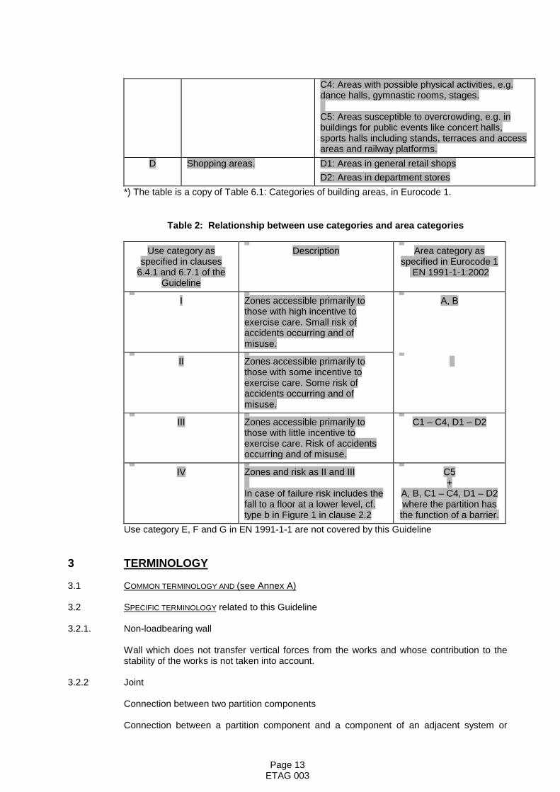
Table 1: Definition of area categories in Eurocode 1 *)
Category Specific Use ExampleA Areas for domestic and
residential activities.Rooms in residential buildings and houses;bedrooms and wards in hospitals; bedrooms inhotels and hostels kitchens and toilets.
B Office areas.C Areas where people may
congregate (with the excep-tion of areas defined undercategory A, B and D).
C1: Areas with tables, etc., e.g. areas in schools,cafés, restaurants, dining halls, reading rooms,receptions.
C2: Areas with fixed seats, e.g. areas in churches,theatres or cinemas, conference rooms, lecturehalls, assembly halls, waiting rooms, railwaywaiting rooms. .
C3: Areas without obstacles for moving people,e.g. areas in museums, exhibition rooms, etc. andaccess areas in public and administrationbuildings, hotels, and railway station forecourts.
Page 13ETAG 003
C4: Areas with possible physical activities, e.g.dance halls, gymnastic rooms, stages.
C5: Areas susceptible to overcrowding, e.g. inbuildings for public events like concert halls,sports halls including stands, terraces and accessareas and railway platforms.
D Shopping areas. D1: Areas in general retail shopsD2: Areas in department stores
*) The table is a copy of Table 6.1: Categories of building areas, in Eurocode 1.
Table 2: Relationship between use categories and area categories
Use category asspecified in clauses
6.4.1 and 6.7.1 of theGuideline
Description Area category asspecified in Eurocode 1
EN 1991-1-1:2002
I Zones accessible primarily tothose with high incentive toexercise care. Small risk ofaccidents occurring and ofmisuse.
A, B
II Zones accessible primarily tothose with some incentive toexercise care. Some risk ofaccidents occurring and ofmisuse.
III Zones accessible primarily tothose with little incentive toexercise care. Risk of accidentsoccurring and of misuse.
C1 – C4, D1 – D2
IV Zones and risk as II and III
In case of failure risk includes thefall to a floor at a lower level, cf.type b in Figure 1 in clause 2.2
C5+
A, B, C1 – C4, D1 – D2where the partition hasthe function of a barrier.
Use category E, F and G in EN 1991-1-1 are not covered by this Guideline
3 TERMINOLOGY
3.1 COMMON TERMINOLOGY AND (see Annex A)
3.2 SPECIFIC TERMINOLOGY related to this Guideline
3.2.1. Non-loadbearing wall
Wall which does not transfer vertical forces from the works and whose contribution to thestability of the works is not taken into account.
3.2.2 Joint
Connection between two partition components
Connection between a partition component and a component of an adjacent system or
Page 14ETAG 003
structure
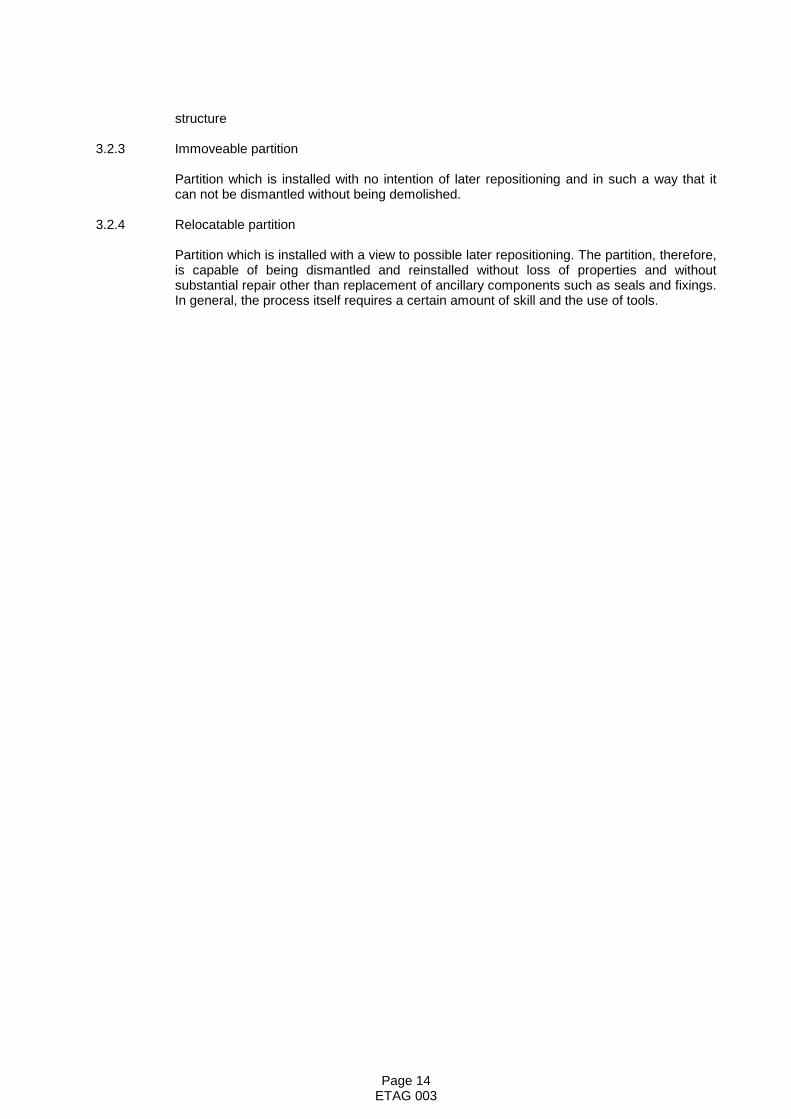
3.2.3 Immoveable partition
Partition which is installed with no intention of later repositioning and in such a way that itcan not be dismantled without being demolished.
3.2.4 Relocatable partition
Partition which is installed with a view to possible later repositioning. The partition, therefore,is capable of being dismantled and reinstalled without loss of properties and withoutsubstantial repair other than replacement of ancillary components such as seals and fixings.In general, the process itself requires a certain amount of skill and the use of tools.
Page 15ETAG 003
Section Two: GUIDANCE FOR THE ASSESSMENT OF THEFITNESS FOR USE
GENERAL NOTES
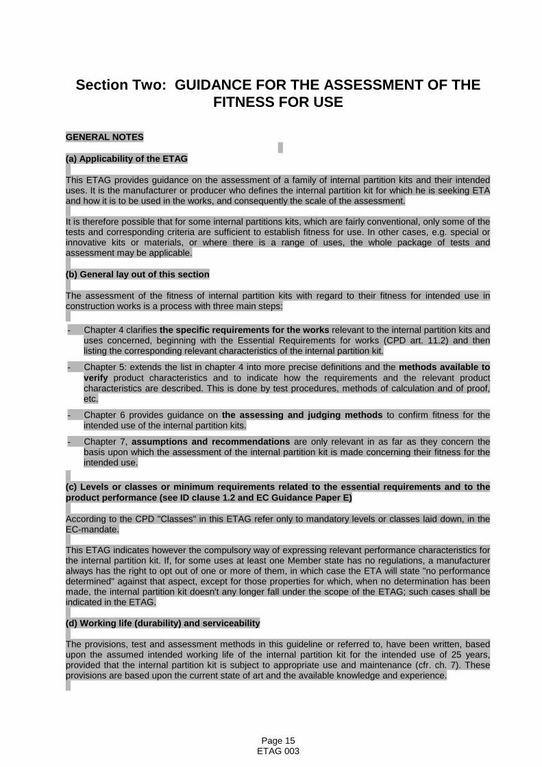
(a) Applicability of the ETAG
This ETAG provides guidance on the assessment of a family of internal partition kits and their intendeduses. It is the manufacturer or producer who defines the internal partition kit for which he is seeking ETAand how it is to be used in the works, and consequently the scale of the assessment.
It is therefore possible that for some internal partitions kits, which are fairly conventional, only some of thetests and corresponding criteria are sufficient to establish fitness for use. In other cases, e.g. special orinnovative kits or materials, or where there is a range of uses, the whole package of tests andassessment may be applicable.
(b) General lay out of this section
The assessment of the fitness of internal partition kits with regard to their fitness for intended use inconstruction works is a process with three main steps:
- Chapter 4 clarifies the specific requirements for the works relevant to the internal partition kits anduses concerned, beginning with the Essential Requirements for works (CPD art. 11.2) and thenlisting the corresponding relevant characteristics of the internal partition kit.
- Chapter 5: extends the list in chapter 4 into more precise definitions and the methods available toverify product characteristics and to indicate how the requirements and the relevant productcharacteristics are described. This is done by test procedures, methods of calculation and of proof,etc.
- Chapter 6 provides guidance on the assessing and judging methods to confirm fitness for theintended use of the internal partition kits.
- Chapter 7, assumptions and recommendations are only relevant in as far as they concern thebasis upon which the assessment of the internal partition kit is made concerning their fitness for theintended use.
(c) Levels or classes or minimum requirements related to the essential requirements and to theproduct performance (see ID clause 1.2 and EC Guidance Paper E)
According to the CPD "Classes" in this ETAG refer only to mandatory levels or classes laid down, in theEC-mandate.
This ETAG indicates however the compulsory way of expressing relevant performance characteristics forthe internal partition kit. If, for some uses at least one Member state has no regulations, a manufactureralways has the right to opt out of one or more of them, in which case the ETA will state "no performancedetermined" against that aspect, except for those properties for which, when no determination has beenmade, the internal partition kit doesn't any longer fall under the scope of the ETAG; such cases shall beindicated in the ETAG.
(d) Working life (durability) and serviceability
The provisions, test and assessment methods in this guideline or referred to, have been written, basedupon the assumed intended working life of the internal partition kit for the intended use of 25 years,provided that the internal partition kit is subject to appropriate use and maintenance (cfr. ch. 7). Theseprovisions are based upon the current state of art and the available knowledge and experience.

Page 16ETAG 003
An "assumed intended working life" means that it is expected that, when an assessment following theETAG-provisions is made, and when this working life has elapsed, the real working life may be, in normaluse conditions, considerably longer without major degradation affecting the essential requirements.
The indications given as to the working life of an internal partition kit cannot be interpreted as a guaranteegiven by the producer or the approval body. They should only be regarded as a means for the specifiersto choose the appropriate criteria for internal partition kits in relation to the expected, economicallyreasonable working life of the works (based upon ID. par. 5.2.2).
(e) Fitness for the intended use
According to the CPD it has to be understood that within the terms of this ETAG, products shall "havesuch characteristics that the works in which they are to be incorporated, assembled, applied or installed,can, if properly designed and built, satisfy the Essential Requirements" (CPD, art. 2.1).
Hence, the internal partition kit must be suitable for use in construction works which (as a whole and intheir separate parts) are fit for their intended use, account being taken of economy, and in order to satisfythe essential requirements. Such requirements must, subject to normal maintenance, be satisfied for aneconomically reasonable working life. The requirements generally concern actions, which are foreseeable."(CPD Annex I, preamble).

Page 17ETAG 003
4 REQUIREMENTS
This chapter identifies the aspects of performance to be examined in order to satisfy therelevant Essential Requirements for Internal Partition Kits for use as non-loadbearing walls,by:
- expressing in more detail, and in terms applicable to the scope of the Guideline, therelevant Essential Requirements of the CPD (given concrete form in the InterpretativeDocuments and further specified in the mandate), for works or parts of the works, takinginto account the durability and serviceability of the works
- applying them to the scope of the Guideline (product/system and intended use), andindicating the resulting relevant product characteristics and possible other aspects.
Each Essential Requirement is considered in turn.
When a product characteristic or other applicable property is specific to one of the EssentialRequirements, it is dealt with in the appropriate place. If, however, the characteristic orproperty is relevant to more than one Essential Requirement, it is addressed under the mostimportant one with cross-reference to the other(s). This is especially important where amanufacturer claims: "No performance determined" for a characteristic or property underone Essential Requirement and it is critical for the assessing and judging under anotherEssential Requirement. Similarly, characteristics or properties, which have a bearing ondurability assessments, may be dealt with under ER 1 to ER 6, with reference to 4.7. Wherethere is a characteristic, which only relates to durability, this is dealt with in 4.7
This chapter also takes into account further requirements, if any (e.g. resulting from otherEC Directives) and identifies aspects of serviceability including specifying characteristicsneeded to identify the internal partition kits. (cfr ETA-format par. II.2).
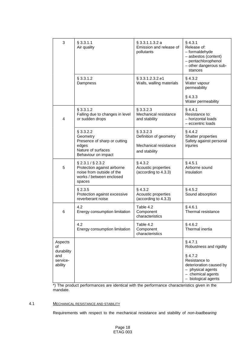
The relevant Essential Requirements, the relevant paragraphs of the corresponding IDs andthe related requirements to product performance are indicated in Table 3.
Table 3: Relationship between ID paragraph for works, ID paragraph for productperformance and ETAG paragraph on product performance
ERCorrespondingID paragraph
for works
CorrespondingID paragraph for
product performance
ETAG paragraphon
product performance *)
1 – – –
2§ 4.2.3.3.1Limitation of the generation offire and smoke within the roomof origin
§ 4.3.1.1Products subject toreaction to firerequirements – walls
§ 4.2.1Reaction to fire
§ 4.2.3.4.2 bLimitation of spread of fire andsmoke beyond the room oforigin
§ 4.3.1.3.5.1Products subject toresistance to firerequirements – partitions
§ 4.2.2Fire resistance
Page 18ETAG 003
3 § 3.3.1.1Air quality
§ 3.3.1.1.3.2 aEmission and release ofpollutants
§ 4.3.1Release of:– formaldehyde– asbestos (content)– pentachlorophenol– other dangerous sub- stances
§ 3.3.1.2Dampness
§ 3.3.1.2.3.2.e1Walls, walling materials
§ 4.3.2Water vapourpermeability
§ 4.3.3Water permeability
4
§ 3.3.1.2Falling due to changes in levelor sudden drops
§ 3.3.2.3Mechanical resistanceand stability
§ 4.4.1Resistance to:– horizontal loads– eccentric loads
§ 3.3.2.2GeometryPresence of sharp or cuttingedgesNature of surfacesBehaviour on impact
§ 3.3.2.3Definition of geometry
Mechanical resistanceand stability
§ 4.4.2Shatter propertiesSafety against personalinjuries
5§ 2.3.1 / § 2.3.2Protection against airbornenoise from outside of theworks / between enclosedspaces
§ 4.3.2Acoustic properties(according to 4.3.3)
§ 4.5.1Airborne soundinsulation
§ 2.3.5Protection against excessivereverberant noise
§ 4.3.2Acoustic properties(according to 4.3.3)
§ 4.5.2Sound absorption
64.2Energy consumption limitation
Table 4.2Componentcharacteristics
§ 4.6.1Thermal resistance
4.2Energy consumption limitation
Table 4.2Componentcharacteristics
§ 4.6.2Thermal inertia
Aspectsofdurabilityandservice-ability
§ 4.7.1Robustness and rigidity
§ 4.7.2Resistance todeterioration caused by– physical agents– chemical agents– biological agents
*) The product performances are identical with the performance characteristics given in themandate.
4.1 MECHANICAL RESISTANCE AND STABILITY
Requirements with respect to the mechanical resistance and stability of non-loadbearing
Page 19ETAG 003
parts of the works are not included in this Essential Requirement but are treated under theEssential Requirement SAFETY IN USE (see clause 4.4.1).
4.2 SAFETY IN CASE OF FIRE
The Essential Requirement laid down in the COUNCIL DIRECTIVE 89/106/EEC is as follows:
The construction works must be designed and built in such a way that in the event of anoutbreak of fire:
- the load-bearing capacity of the construction can be assumed for a specific period oftime.
- the generation and spread of fire and smoke within the works are limited.
- the spread of fire to neighbouring construction works is limited.
- occupants can leave the works or be rescued by other means.
- the safety of rescue teams is taken into consideration.
The following aspects of performance are relevant to this Essential Requirement for InternalPartition Kits:
4.2.1 Reaction to fire
The reaction to fire performance of the products and/or components of the partition kit shallbe in accordance with laws, regulations and administrative provisions, applicable to thepartition kit in its end use application. This performance shall be expressed in the form of aclassification specified in accordance with the relevant EC decision and the appropriate CENclassification standards.
4.2.2 Fire resistance
The resistance to fire performance of the partition shall be in accordance with laws,regulations and administrative provisions, applicable to the kit in its end use application.This performance shall be expressed in the form of a classification specified in accordancewith the relevant EC decision and the appropriate CEN classification standards.
4.3 HYGIENE, HEALTH AND THE ENVIRONMENT
The Essential Requirement laid down in the COUNCIL DIRECTIVE 89/106/EEC is as follows:
The construction work must be designed and built in such a way that it will not be a threat tothe hygiene or health of the occupants or neighbours, in particular as a result of any of thefollowing:
- the giving-off of toxic gases
- the presence of dangerous particles or gases in the air
- the emission of dangerous radiation
- pollution or poisoning of the water or soil
- faulty elimination of waste water, smoke, solid or liquid wastes
- the presence of damp in parts of the works or on surfaces within the works.
The following aspects of performance are relevant to this Essential Requirement for InternalPartition Kits:
Page 20ETAG 003
4.3.1 Release and/or content of formaldehyde, asbestos, pentachlorophenol and other dangeroussubstances
Materials forming the partition kit shall be such that, when installed according to theappropriate provisions of the Member States, it allows for the satisfaction of the ER3 of theCPD as expressed by the national provisions of the Member States and in particular doesnot cause harmful emission of toxic gases, dangerous particles or radiation to the indoorenvironment nor contamination of the outdoor environment (air, soil or water).
4.3.2 Water vapour permeability
The partition shall be designed and installed in such a way that moisture transfer through thepartition does not cause water vapour to condense within the partition or on its surfaceadversely affecting the properties of the partition.
4.3.3 Water permeability
Requirements regarding the water permeability (watertightness) of partitions are relevantonly where partitions are used in environments where they are exposed directly to water,e.g. in bathrooms, washrooms, dairies and abattoirs. Such requirements relate to theperformance of the covering system and shall be dealt with in separate technicalspecifications on the watertightness of wall coverings.
4.4 SAFETY IN USE
The Essential Requirement laid down in the COUNCIL DIRECTIVE 89/106/EEC is as follows:
The construction works must be designed and built in such a way that it does not presentunacceptable risks of accidents in service or in operation such as slipping, falling, collision,burns, electrocution, injury from explosion.
The following aspects of performance are relevant to this Essential Requirement for InternalPartition Kits:
4.4.1 Resistance to horizontal and eccentric loads
The partition shall have sufficient mechanical resistance and stability to ensure that thesafety of the occupants is not endangered.
This means that it shall have sufficient mechanical resistance and stability to withstandaccidentally large static or dynamic loads, from the action of persons or objects, without fullor partial collapse causing dangerous (sharp or cutting) fragments, giving risk of fallingthrough, particularly at a change of level, or endangering the safety of other people.
The loads may be in the form of:
- impacts resulting from a person falling against the partition
- differential air pressure
- a large number of people leaning or pressing against the partition at the same time(crowd pressure)
- impacts resulting from the movement of heavy non-deformable objects such as piecesof furniture or equipment
- slamming of doors
- heavy objects such as furniture and sanitary or heating equipment.
4.4.2 Safety against personal injuries by contact
Page 21ETAG 003
Partitions shall be designed and installed with due consideration to passive safety to preventoccupants from injury by the partition under normal conditions or to prevent unnecessaryinjuries being inflicted on a person who accidentally falls against the partition. Thecharacteristics of the partition affecting the level of risk include:
- Geometry
Windows opening into circulation spaces, positioning of doors, headroom.
- Existence of sharp or cutting edges
Joints, corners, trim details.
- Nature of surfaces
Surface texture.
4.5 PROTECTION AGAINST NOISE
The Essential Requirement laid down in the COUNCIL DIRECTIVE 89/106/EEC is as follows:
The construction works must be designed and built in such a way that noise perceived bythe occupants or people nearby is kept down to a level that will not threaten their health andwill allow them to sleep, rest and work in satisfactory conditions.
The following aspects of performance are relevant to this Essential Requirement for InternalPartition Kits:
4.5.1 Airborne sound insulation
Transmission of airborne sound across partitions shall be in accordance with laws,regulations and administrative provisions, applicable for the location where the product isincorporated in the works.
4.5.2 Sound absorption
Sound absorption is considered only in case of partitions with a factory-made finish.
The acoustic qualities of the surface of a partition shall meet any relevant requirements withrespect to reverberation time.
4.6 ENERGY ECONOMY AND HEAT RETENTION
The Essential Requirement laid down in the COUNCIL DIRECTIVE 89/106/EEC is as follows:
The construction works and its heating and ventilation installations must be designed andbuilt in such a way that the amount of energy required in use shall be low, having regard tothe climatic conditions of the location and the occupants.
The following aspects of performance are relevant to this Essential Requirement for InternalPartition Kits:
4.6.1 Thermal resistance
The thermal transmittance/resistance of the partition shall be in accordance with laws,regulations and administrative provisions, applicable for the location where the product isincorporated in the works.
If there is any discontinuity in assembled panels, then the effect of a thermal bridging shallbe considered.

Page 22ETAG 003
4.6.2 Thermal inertia
The thermal inertia of a partition shall be established in cases where this characteristic isrequired to determine the energy consumption of the works (for heating and/or for cooling).
4.7 ASPECTS OF DURABILITY AND SERVICEABILITY
The following requirements relate to the Essential Requirements, but not to any individualEssential Requirement. As a consequence, failure to meet these requirements may result inone or more of the Essential Requirements no longer being met.
4.7.1 Robustness and rigidity
The partition shall have sufficient robustness and rigidity to maintain integrity and thereforeensure the continued fulfilment of relevant Essential Requirements.
This means that it shall have the sufficient robustness and rigidity to withstand static ordynamic loads from the action of people or objects without apparent damage, inconvenientdeflection or impression of lack of stability.
The loads may be in the form of:
- impacts resulting from a person falling against the partition
- differential air pressure
- a large number of people leaning or pressing against the partition at the same time(crowd pressure)
- impacts resulting from the movement of light non-deformable objects such as pieces offurniture or cleaning tools.
- slamming of doors
- heavy objects, such as furniture and sanitary or heating equipment
- light objects, such as pictures, lamps or small pieces of furniture
In addition, partitions intended for ceramic tiling require greater rigidity to ensure that thecovering remains intact.
4.7.2 Resistance to deterioration
To prevent reduction in mechanical or other properties, partition components and theirpossible finishes shall be protected against / resistant to deterioration caused by physical,chemical or biological agents. The agents include:
4.7.2.1 Physical agents
Hygrothermal conditions.
The partition, including its joints, shall not be adversely affected (e.g. deterioration,distortion, deformation) by the following conditions:
- Variations in temperature/humidity where the same changes occur on both sides of thepartition at the same time. (Example: Office heating can be reduced or even switchedoff at night and during weekends or national holidays. Office temperatures can dropfrom up to 25 °C to around 5 °C with consequential increases in relative humidity.)
- Differences in temperature and/or relative humidity on one side of a partition comparedto the other. (Example: Office at up to 25 °C located within an unheated warehouse,

Page 23ETAG 003
where the office temperature is maintained and the warehouse side varies from justabove freezing, during winter, to 30 °C in summer.)
- Localised heating from heating panels or radiators located next to the partition.
4.7.2.2 Chemical agents
Water, carbon dioxide, oxygen (possible corrosion) and other normal chemical hazardslikely to come into contact, for example cleaning materials (resistance to cleaning agents isconsidered only in the case of partitions or components with a factory made finish).
4.7.2.3 Biological agents
Fungi, bacteria, algae and insects.
The partition shall be designed and built in such a way that it does not encourage infestationby insects or vermin.
4.7.3 Identification
The products shall be precisely defined by reference to relevant characteristics.
Page 24ETAG 003
5. METHODS OF VERIFICATION
This chapter refers to the verification methods used to determine the various aspects ofperformance of the products in relation to the requirements for the works (calculations, tests,engineering knowledge, site experience, etc.) as set out in chapter 4.
The relevant Essential Requirements, the related requirements to product performances (asgiven in Chapter 4), the corresponding product characteristics to be assessed and thecorresponding verification methods are indicated in Table 5.1.
Not all the requirements in the following section will be relevant to every product. A ‘Noperformance determined’ option is possible in some cases and it will be for the manufacturerto decide, taking account of their intended market and which options they wish to haveassessed.
It is possible to use existing data from recognized laboratories with expertise in testing ofinternal partition kits and having an adequate quality system, which includes the calibrationof testing equipment. The possibility exists to use existing data in accordance with the EOTAGuidance Document No 004 on ‘The provision of data for assessment leading to ETA’. It isthe responsibility of the EOTA Technical Board to ensure that the intentions of the testsmentioned in this chapter are fulfilled.
Based on existing data and/or the claimed performance of the internal partition kit by themanufacturer, the approval body may decide that not all investigations mentioned in thischapter are necessary and the Approval Body has the discretion to develop a suitableprogramme for the assessment of internal partition kit taking account of the intended useand the claimed performance.
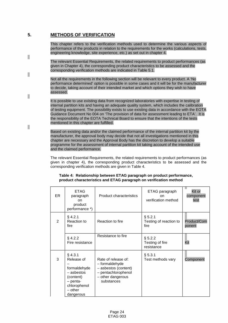
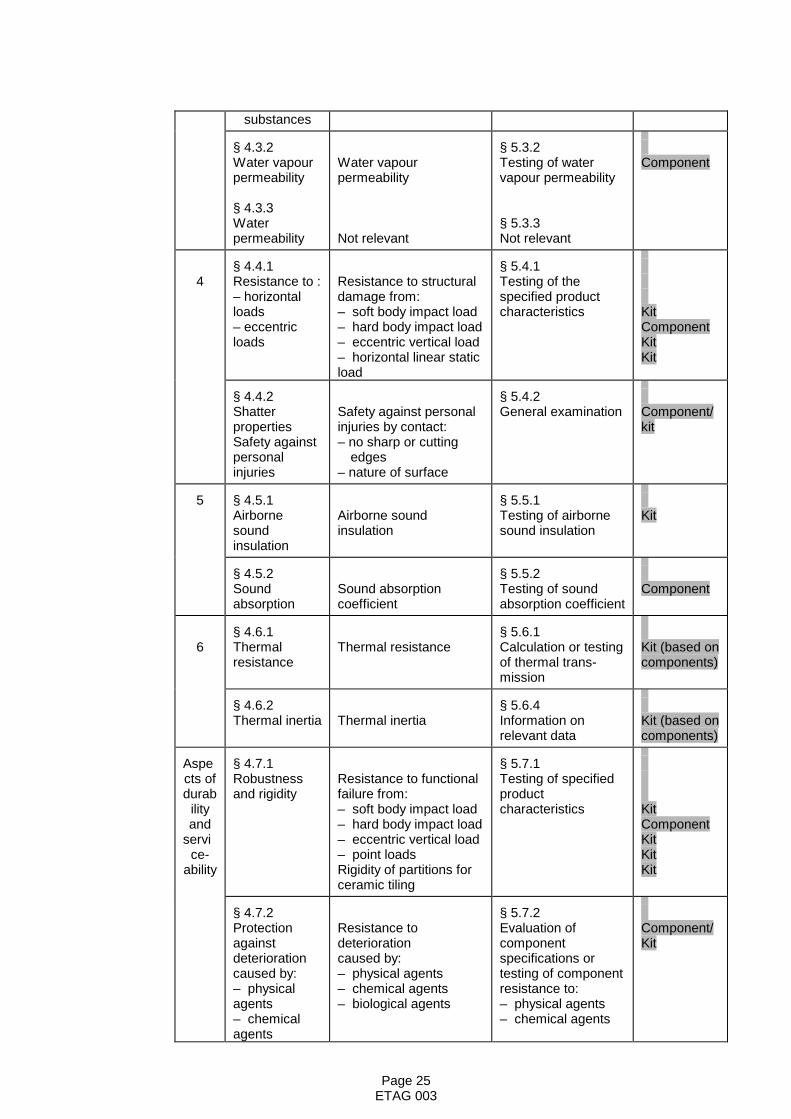
The relevant Essential Requirements, the related requirements to product performances (asgiven in chapter 4), the corresponding product characteristics to be assessed and thecorresponding verification methods are given in Table 4.
Table 4: Relationship between ETAG paragraph on product performance,product characteristics and ETAG paragraph on verification method
ERETAG
paragraphon
productperformance *)
Product characteristicsETAG paragraph
onverification method
Kit orcomponent
test
2§ 4.2.1Reaction tofire
Reaction to fire§ 5.2.1Testing of reaction tofire
Product/Component
§ 4.2.2Fire resistance
Resistance to fire § 5.2.2Testing of fireresistance
Kit
3§ 4.3.1Release of–formaldehyde– asbestos(content)– penta-chlorophenol– otherdangerous
Rate of release of:– formaldehyde– asbestos (content)– pentachlorophenol– other dangerous
substances
§ 5.3.1Test methods vary Component
Page 25ETAG 003
substances
§ 4.3.2Water vapourpermeability
§ 4.3.3Waterpermeability
Water vapourpermeability
Not relevant
§ 5.3.2Testing of watervapour permeability
§ 5.3.3Not relevant
Component
4§ 4.4.1Resistance to :– horizontalloads– eccentricloads
Resistance to structuraldamage from:– soft body impact load– hard body impact load– eccentric vertical load– horizontal linear staticload
§ 5.4.1Testing of thespecified productcharacteristics Kit
ComponentKitKit
§ 4.4.2ShatterpropertiesSafety againstpersonalinjuries
Safety against personalinjuries by contact:– no sharp or cutting
edges– nature of surface
§ 5.4.2General examination Component/
kit
5 § 4.5.1Airbornesoundinsulation
Airborne soundinsulation
§ 5.5.1Testing of airbornesound insulation
Kit
§ 4.5.2Soundabsorption
Sound absorptioncoefficient
§ 5.5.2Testing of soundabsorption coefficient
Component
6§ 4.6.1Thermalresistance
Thermal resistance§ 5.6.1Calculation or testingof thermal trans-mission
Kit (based oncomponents)
§ 4.6.2Thermal inertia Thermal inertia
§ 5.6.4Information onrelevant data
Kit (based oncomponents)
Aspects ofdurab
ilityand
service-
ability
§ 4.7.1Robustnessand rigidity
Resistance to functionalfailure from:– soft body impact load– hard body impact load– eccentric vertical load– point loadsRigidity of partitions forceramic tiling
§ 5.7.1Testing of specifiedproductcharacteristics Kit
ComponentKitKitKit
§ 4.7.2Protectionagainstdeteriorationcaused by:– physicalagents– chemicalagents
Resistance todeteriorationcaused by:– physical agents– chemical agents– biological agents
§ 5.7.2Evaluation ofcomponentspecifications ortesting of componentresistance to:– physical agents– chemical agents
Component/Kit
Page 26ETAG 003
– biologicalagents
– biological agents
*) The product performances are identical with the performance characteristics given in themandate.
5.1 MECHANICAL RESISTANCE AND STABILITY
Requirements regarding the mechanical resistance and stability of non-loadbearing parts ofthe work is not included in this Essential Requirement but treated under the EssentialRequirement SAFETY IN USE see clause 5.4.1.
5.2 SAFETY IN CASE OF FIRE
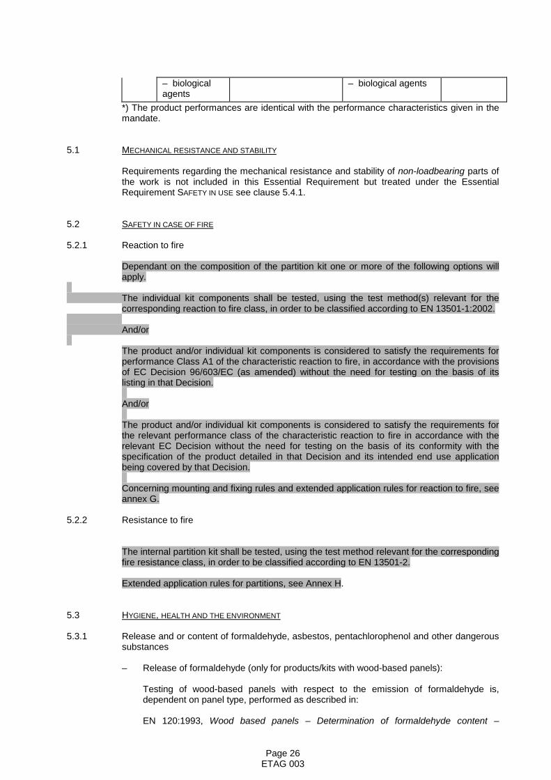
5.2.1 Reaction to fire
Dependant on the composition of the partition kit one or more of the following options willapply.
The individual kit components shall be tested, using the test method(s) relevant for thecorresponding reaction to fire class, in order to be classified according to EN 13501-1:2002.
And/or
The product and/or individual kit components is considered to satisfy the requirements forperformance Class A1 of the characteristic reaction to fire, in accordance with the provisionsof EC Decision 96/603/EC (as amended) without the need for testing on the basis of itslisting in that Decision.
And/or
The product and/or individual kit components is considered to satisfy the requirements forthe relevant performance class of the characteristic reaction to fire in accordance with therelevant EC Decision without the need for testing on the basis of its conformity with thespecification of the product detailed in that Decision and its intended end use applicationbeing covered by that Decision.
Concerning mounting and fixing rules and extended application rules for reaction to fire, seeannex G.
5.2.2 Resistance to fire
The internal partition kit shall be tested, using the test method relevant for the correspondingfire resistance class, in order to be classified according to EN 13501-2.
Extended application rules for partitions, see Annex H.
5.3 HYGIENE, HEALTH AND THE ENVIRONMENT
5.3.1 Release and or content of formaldehyde, asbestos, pentachlorophenol and other dangeroussubstances
– Release of formaldehyde (only for products/kits with wood-based panels):
Testing of wood-based panels with respect to the emission of formaldehyde is,dependent on panel type, performed as described in:
EN 120:1993, Wood based panels – Determination of formaldehyde content –

Page 27ETAG 003
Extraction method called the perforator method
EN 717-2:1995, Wood-based panels – Determination of formaldehyde release – Part 2:Formaldehyde release by the gas analysis method
EN 717-3:1997, Wood-based panels – Determination of formaldehyde release – Part 3:Formaldehyde release by the flask method
following EN 13986
– Release of asbestos (content):
There is no test method available concerning testing of materials with respect to thecontent of asbestos. Where components of the partition kit contain asbestos, themanufacturer shall give information on the content of:
CrocidoliteAmositeAnthophyliteTremolite.Chrysotile
– Release of pentachlorophenol:
Determination of the PCP content shall be performed in accordance with a test thatreflects the state of the art
– Release of other dangerous substances:
Presence of dangerous substances in the productThe applicant shall submit a written declaration stating whether or not the product/kitcontains dangerous substances according to European and national regulations, when andwhere relevant in the Member States of destination, and shall list these substances.
Compliance with the applicable regulationsIf the product/kit contains dangerous substances as declared above, the ETA will providethe method(s) which has been used for demonstrating compliance with the applicableregulations in the Member States of destination, according to the dated EU data-base(method(s) of content or release, as appropriate).
Application of the precautionary principleAn EOTA member has the possibility to provide to the other members, through theSecretary General, warning about substances, which according to Health authorities of itscountry, are considered to be dangerous under sound scientific evidence, but are not yetregulated. Complete references about this evidence will be provided.
This information once agreed upon, will be kept in an EOTA database, and will betransferred to the Commission services.
The information contained in this EOTA database will also be communicated to any ETAapplicant.On the basis of this information, a protocol of assessment of the product, regarding thissubstance, could be established on request of a manufacturer with the participation of theApproval Body, which raised the issue.The abovementioned test methods and provisions apply to the individual components of thekit.
5.3.2 Water vapour permeability
The risk of interstitial or internal surface condensation, including possible joints, shall be
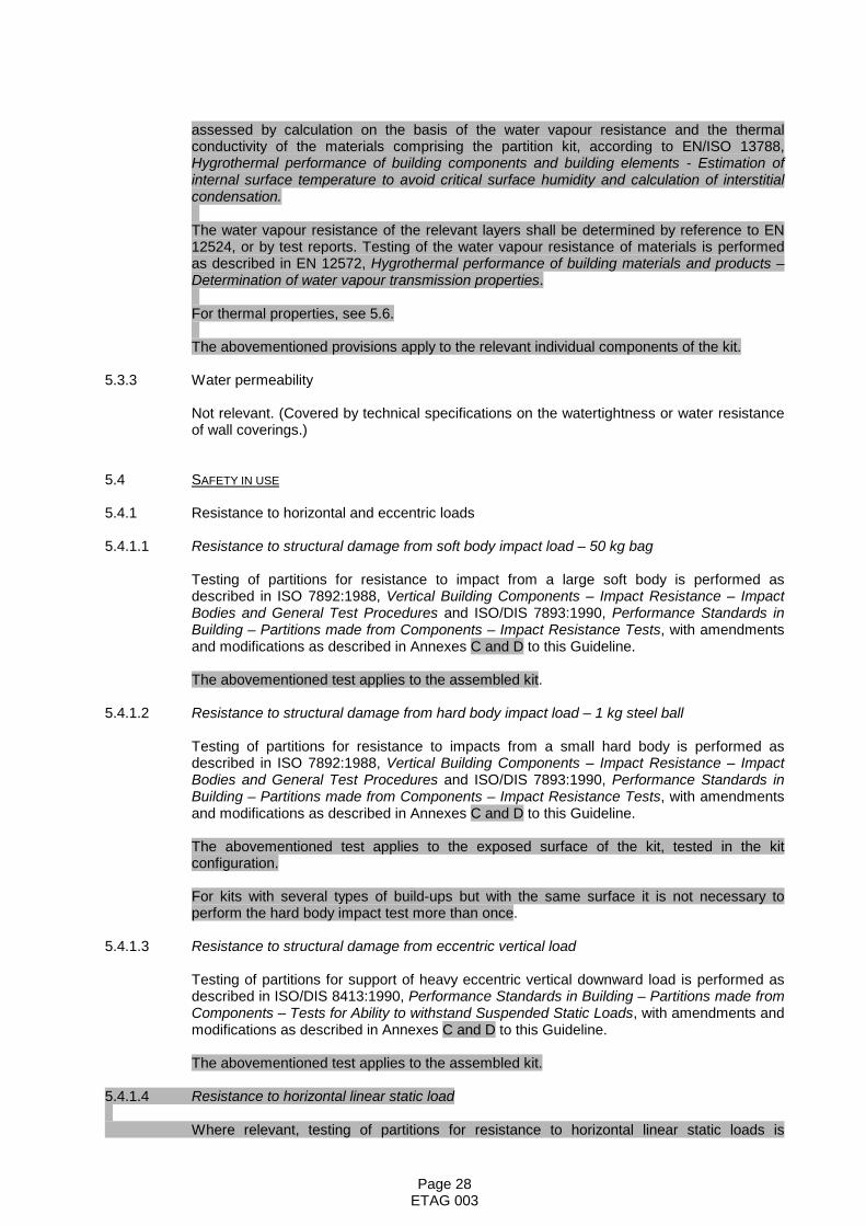
Page 28ETAG 003
assessed by calculation on the basis of the water vapour resistance and the thermalconductivity of the materials comprising the partition kit, according to EN/ISO 13788,Hygrothermal performance of building components and building elements - Estimation ofinternal surface temperature to avoid critical surface humidity and calculation of interstitialcondensation.
The water vapour resistance of the relevant layers shall be determined by reference to EN12524, or by test reports. Testing of the water vapour resistance of materials is performedas described in EN 12572, Hygrothermal performance of building materials and products –Determination of water vapour transmission properties.
For thermal properties, see 5.6.
The abovementioned provisions apply to the relevant individual components of the kit.
5.3.3 Water permeability
Not relevant. (Covered by technical specifications on the watertightness or water resistanceof wall coverings.)
5.4 SAFETY IN USE
5.4.1 Resistance to horizontal and eccentric loads
5.4.1.1 Resistance to structural damage from soft body impact load – 50 kg bag
Testing of partitions for resistance to impact from a large soft body is performed asdescribed in ISO 7892:1988, Vertical Building Components – Impact Resistance – ImpactBodies and General Test Procedures and ISO/DIS 7893:1990, Performance Standards inBuilding – Partitions made from Components – Impact Resistance Tests, with amendmentsand modifications as described in Annexes C and D to this Guideline.
The abovementioned test applies to the assembled kit.
5.4.1.2 Resistance to structural damage from hard body impact load – 1 kg steel ball
Testing of partitions for resistance to impacts from a small hard body is performed asdescribed in ISO 7892:1988, Vertical Building Components – Impact Resistance – ImpactBodies and General Test Procedures and ISO/DIS 7893:1990, Performance Standards inBuilding – Partitions made from Components – Impact Resistance Tests, with amendmentsand modifications as described in Annexes C and D to this Guideline.
The abovementioned test applies to the exposed surface of the kit, tested in the kitconfiguration.
For kits with several types of build-ups but with the same surface it is not necessary toperform the hard body impact test more than once.
5.4.1.3 Resistance to structural damage from eccentric vertical load
Testing of partitions for support of heavy eccentric vertical downward load is performed asdescribed in ISO/DIS 8413:1990, Performance Standards in Building – Partitions made fromComponents – Tests for Ability to withstand Suspended Static Loads, with amendments andmodifications as described in Annexes C and D to this Guideline.
The abovementioned test applies to the assembled kit.
5.4.1.4 Resistance to horizontal linear static load
Where relevant, testing of partitions for resistance to horizontal linear static loads is
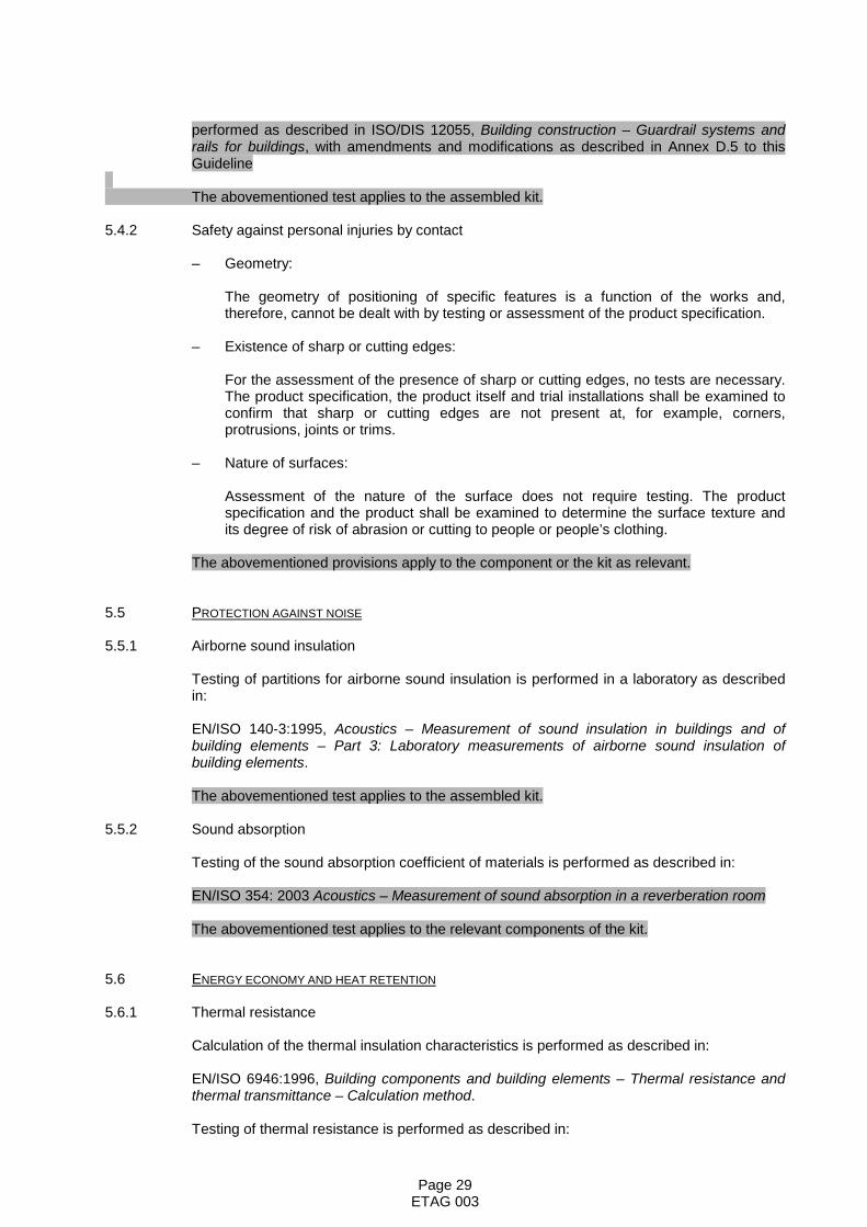
Page 29ETAG 003
performed as described in ISO/DIS 12055, Building construction – Guardrail systems andrails for buildings, with amendments and modifications as described in Annex D.5 to thisGuideline
The abovementioned test applies to the assembled kit.
5.4.2 Safety against personal injuries by contact
– Geometry:
The geometry of positioning of specific features is a function of the works and,therefore, cannot be dealt with by testing or assessment of the product specification.
– Existence of sharp or cutting edges:
For the assessment of the presence of sharp or cutting edges, no tests are necessary.The product specification, the product itself and trial installations shall be examined toconfirm that sharp or cutting edges are not present at, for example, corners,protrusions, joints or trims.
– Nature of surfaces:
Assessment of the nature of the surface does not require testing. The productspecification and the product shall be examined to determine the surface texture andits degree of risk of abrasion or cutting to people or people’s clothing.
The abovementioned provisions apply to the component or the kit as relevant.
5.5 PROTECTION AGAINST NOISE
5.5.1 Airborne sound insulation
Testing of partitions for airborne sound insulation is performed in a laboratory as describedin:
EN/ISO 140-3:1995, Acoustics – Measurement of sound insulation in buildings and ofbuilding elements – Part 3: Laboratory measurements of airborne sound insulation ofbuilding elements.
The abovementioned test applies to the assembled kit.
5.5.2 Sound absorption
Testing of the sound absorption coefficient of materials is performed as described in:
EN/ISO 354: 2003 Acoustics – Measurement of sound absorption in a reverberation room
The abovementioned test applies to the relevant components of the kit.
5.6 ENERGY ECONOMY AND HEAT RETENTION
5.6.1 Thermal resistance
Calculation of the thermal insulation characteristics is performed as described in:
EN/ISO 6946:1996, Building components and building elements – Thermal resistance andthermal transmittance – Calculation method.
Testing of thermal resistance is performed as described in:

Page 30ETAG 003
EN/ISO 8990:November 1995, Thermal Insulation – Determination of steady-state thermaltransmission properties – Calibrated and guarded hot box.
prEN 12667:1996, Building materials - Determination of thermal resistance by means ofguarded hot plate and heat flow meter methods - Products of high and medium thermalresistance.
prEN 12939:1997, Building materials - Determination of thermal resistance by means ofguarded hot plate and heat flow meter methods - Thick products of high and mediumthermal resistance.
EN/ISO 10211-1:1995, Thermal bridges in building constructions – Part 1: Heat flows andsurface temperatures – General calculation methods
EN/ISO 10211-2:1995, Thermal bridges in building constructions – Part 2: Heat flows andsurface temperatures – General calculation of linear thermal bridges.
The abovementioned tests apply to the assembled kit, based on the characteristics of thecomponents constituting the kit.
5.6.2 Thermal inertia
To make it possible to calculate the thermal inertia of the partition, information on thefollowing properties of the partition shall be given:
– total mass per unit area (in kg/m2)
– density of materials used (in kg/m3)
– heat capacity of materials used (in J/kg K)
– thermal transmittance of materials used (in W/m2 K).
The abovementioned provisions apply to the assembled kit, based on the characteristics ofthe components constituting the kit.
5.7 ASPECTS OF DURABILITY AND SERVICEABILITY
5.7.1 Robustness and rigidity
5.7.1.1 Resistance to functional failure from soft body impact load – 50 kg bag
Testing of partitions for resistance to impact from a large soft body is performed asdescribed in ISO 7892:1988, Vertical Building Components – Impact Resistance – ImpactBodies and General Test Procedures and ISO/DIS 7893:1990, Performance Standards inBuilding – Partitions made from Components – Impact Resistance Tests, with amendmentsand modifications as described in Annexes C and D to this Guideline.
The abovementioned test applies to the assembled kit.
5.7.1.2 Resistance to functional failure from hard body impact load – 0.5 kg steel ball
Testing of partitions for resistance to impact from small non-deformable objects isperformed as described in ISO 7892:1988, Vertical Building Components – ImpactResistance – Impact Bodies and General Test Procedures and ISO/DIS 7893:1990,Performance Standards in Building – Partitions made from Components – Impact
Page 31ETAG 003
Resistance Tests, with amendments and modifications as described in Annexes C and D tothis Guideline.
The abovementioned test applies to the exposed surface of the kit, tested in the kitconfiguration.
5.7.1.3 Resistance to functional failure from eccentric vertical load
Testing of partitions for support of heavy eccentric vertical downward load is performed asdescribed in ISO/DIS 8413:1990, Performance Standards in Building – Partitions made fromComponents – Tests for Ability to withstand Suspended Static Loads, with amendments andmodifications as described in Annexes C and D to this Guideline.
The abovementioned test applies to the assembled kit.
5.7.1.4 Resistance to functional failure from point loads parallel or perpendicular to the surface
Testing of partitions for resistance to point loads parallel or perpendicular to (away from) thesurface of the partition is performed as described in ISO/DIS 8413:1990, PerformanceStandards in Building – Partitions made from Components – Tests for Ability to withstandSuspended Static Loads.
The abovementioned test applies to the assembled kit.
5.7.1.5 Rigidity of partitions to be used as a substrate for ceramic tiling
Testing of sufficient strength and rigidity of partitions to be used as a substrate for ceramictiling is performed as described in Annex E to this Guideline. The test is carried out in placeof the test described in clause 5.7.1.1, and not as a supplement to it.
The abovementioned test applies to the exposed surface of the kit, tested in the kitconfiguration.
5.7.2 Protection against deterioration
The below mentioned provisions and test methods apply to the relevant individualcomponents of the kit
5.7.2.1 Physical agents
Hygrothermal conditions.
The product specification shall be examined and the materials used assessed for hygro-thermal performance primarily in respect of movement.
Where materials of known composition and performance are used, an assessment can bemade and no testing is required.
For partitions of complex composition or incorporating hygroscopic materials, ahygrothermal test (see below) may be carried out as follows: A test sample that fullyrepresents the partition under consideration shall be submitted to the following hygrothermalconditions:
– an atmosphere of 20 °C – 25 °C on either side of the partition at 25 %RH – 30 %RH for7 days, then the temperature is reduced to 5 °C for 7 days
– an atmosphere of 20 °C – 25 °C at 25 %RH – 30 %RH on one side and 0 °C – 5 °C at

Page 32ETAG 003
85 %RH – 95 %RH on the other for a period of 28 days
– for the effects of radiation, the partition shall be subjected on one of the faces to alocalised radiation allowing the temperature of the exposed parts to be brought tomaximum 50 °C ± 5 °C for 6 hours.
After each test, the deflection of the partition is measured.
5.7.2.2 Chemical agents
– corrosion
The possible test methods for corrosion depend on the materials used in the kit, e.g.
EN 13523-8 2002: Coil coated metals - Test methods - Resistance to salt spray
– cleaning agents
The product specification shall be examined to determine the nature of the surfaces.
Where materials of known composition and performance are used, an assessment canbe made and no testing is required.
Where materials of unknown composition and performance are used, or where themanufacturer makes specific claims, or where the location of the partition is such thatcleaning is an important requirement, tests shall be conducted in accordance with EN423: 1993, Resilient floor coverings – Determination of the effect of stains to check thereaction of the partition to substances it is likely to encounter in service.
5.7.2.3 Biological agents
The product specification shall be examined and the materials used assessed to determinewhether the protection against fungi, bacteria, algae and insects is appropriate for theintended use and whether they will provide food value or contain voids suitable for habitationby vermin. The possible test methods depend on the materials used in the kit
5.7.3 Identification
The identification parameters shall be chosen appropriately, so that they give a clearunderstanding of the properties of the product, e.g.
• Fingerprinting (infrared, gas chromatography, etc)• Formulation (chemical constitution, recipes, composition of raw
materials, amounts, components specified by characteristics,compliance with other specifications eg. ENs or by weight, volume,percentage, etc)
• Manufacturing process parameters (temperature, pressure, time …product/production codes)
• Testing of physical characteristics - data (geometry, density,mechanical strength, etc)
• Calculations, detailing, drawings
Whichever method(s) is/are used it is necessary to recognise practical tolerancesin relation to results/data collected.

Page 33ETAG 003
6. ASSESSING AND JUDGINGthe fitness for use of products for an intended use
Chapter 6 details the performance requirements to be met by an Internal Partition Kit (chapter 4) into precise and measurable (as far as possible and proportional to theimportance of the risk) or qualitative terms, related to the products and their intended use,using the verification methods (chapter 5).
Each performance requirement to be met for a given intended use, in general is assessed interms of classes, use categories or numerical values. In general, the ETA shall eitherindicate the result of these assessments or state “No performance determined” (forcountries/regions /buildings where no requirements given in laws, regulations andadministrative provisions are applicable). This statement does not mean that the partitionperforms badly, but merely that this specific performance property has not been tested andassessed.
The possible ways of expressing the results of the assessment of the mandatoryperformance requirements are given in Table 5.
Table 5: Relationship between product performance to be assessed and expressionsof classification, categorization and declaration
ER ETAG paragraph on productperformance to be assessed
ClassUse categoryNumeric value
2§ 6.2.1Reaction to fire Euroclasses A1 – F
§ 6.2.2Fire resistance Classification
No performance determined
3§ 6.3.1Release of:– formaldehyde– asbestos (content)– pentachlorophenol– other dangerous substances
Formaldehyde class (Wood-based panels)Indication of content of asbestosIndication of content of pentachlorophenolIndication of other dangerous materials“No dangerous materials”No performance determined
§ 6.3.2Water vapour permeability
§ 6.3.3Water permeability
Water vapour resistance of materialsNo performance determined
Not relevant
4§ 6.4.1Resistance to horizontal andeccentric loads– Resistance to dynamic loads
– Resistance to eccentric vertical loads
– Resistance to horizontal linearstatic loads
Use category I, II, III or IV
Loading use category A or BNo performance determinedCharacteristic valueNo performance determined

Page 34ETAG 003
§ 6.4.2Safety against personal injury bycontact
DescriptionNo performance determined
5§ 6.5.1Airborne sound insulation Single number rating
No performance determined
§ 6.5.2Sound absorption Single number rating
No performance determined
6§ 6.6.1Thermal resistance R-value
No performance determined
§ 6.6.2Thermal inertia Information on relevant data
No performance determined
Aspectsof
durabilityand
serviceability
§ 6.7.1Robustness and rigidity– Resistance to dynamic loads
– Resistance to eccentric vertical loads
– Resistance to point loads
– Rigidity of partitions for ceramic tiling
Use category I, II, III or IV
Loading category A or BNo performance determined
AcceptableNo performance determined
Pass/failNo performance determined
§ 6.7.2Resistance to deterioration causedby:– physical agents– chemical agents– biological agents
AcceptableAcceptableAcceptable
6.1 MECHANICAL RESISTANCE AND STABILITY
As partitions are non-loadbearing parts of the work, they are not required to meet this EssentialRequirement.
6.2 SAFETY IN CASE OF FIRE
6.2.1 Reaction to fire
The product and/or the kit components shall be classified according to EN 13501-1:2002.
6.2.2 Fire resistance
The assembled kit shall be classified according to EN 13501-2.

Page 35ETAG 003
6.3 HYGIENE, HEALTH AND THE ENVIRONMENT
6.3.1 Release and/or content of formaldehyde, asbestos, pentachlorophenol and other dangeroussubstances
– Release of formaldehyde (only for kits with wood-based panels):
The wood based panels shall comply with the emission classes according to annex Bof EN 13986
– Release of asbestos (content):
The content of the following materials, as stated by the manufacturer, shall be given asa percentage by mass of the component containing the asbestos:
CrocidoliteAmositeAnthophyliteTremoliteChrysotile.
– Release of pentachlorophenol:
The concentration of PCP must not exceed 5 ppm in accordance with EN 13986
– Release of other dangerous substances:
The product/kit shall comply with all relevant European and national provisionsapplicable for the uses for which it is brought to the market. The attention of theapplicant should be drawn on the fact that for other uses or other Member States ofdestination there may be other requirements, which would have to be respected. Fordangerous substances contained in the product but not covered by the ETA, the NPDoption (no performance determined) is applicable
6.3.2 Water vapour permeability
The product specifications shall be examined and performance in respect of exposure tomoisture assessed on the basis of known material properties, design details and theintended use. Where properties such as water vapour permeability are not known, they shallbe determined by testing.
It shall be established that condensation in the partition as a result of water vapour diffusionwill not occur or will occur only to an extent where damage is not caused during thecondensation period and the partition will dry out again during the evaporation period.
6.3.3 Water permeability
No performance determined. (Covered by technical specifications on the watertightness orwater resistance of wall coverings.)
6.4 SAFETY IN USE
6.4.1 Resistance to horizontal and eccentric loads
This assessment addresses the Essential Requirement for SAFETY IN USE and Aspects ofdurability and serviceability (clause 6.7.1). Several aspects of performance are assessed,from which an overall assessment of the robustness of the system can be drawn.
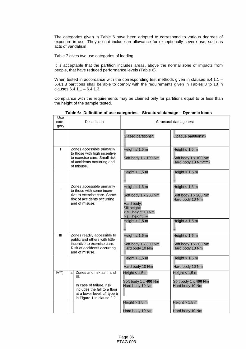
Page 36ETAG 003
The categories given in Table 6 have been adopted to correspond to various degrees ofexposure in use. They do not include an allowance for exceptionally severe use, such asacts of vandalism.
Table 7 gives two use categories of loading.
It is acceptable that the partition includes areas, above the normal zone of impacts frompeople, that have reduced performance levels (Table 6).
When tested in accordance with the corresponding test methods given in clauses 5.4.1.1 –5.4.1.3 partitions shall be able to comply with the requirements given in Tables 8 to 10 inclauses 6.4.1.1 – 6.4.1.3.
Compliance with the requirements may be claimed only for partitions equal to or less thanthe height of the sample tested.
Table 6: Definition of use categories – Structural damage – Dynamic loadsUse
category
Description Structural damage test
Glazed partitions*) Opaque partitions*)
I Zones accessible primarilyto those with high incentiveto exercise care. Small riskof accidents occurring andof misuse.
Height ≤ 1,5 m
Soft body 1 x 100 Nm
Height ≤ 1,5 m
Soft body 1 x 100 NmHard body 10 Nm****)
Height > 1,5 m
–
Height > 1,5 m
–II Zones accessible primarily
to those with some incen-tive to exercise care. Somerisk of accidents occurringand of misuse.
Height ≤ 1,5 m
Soft body 1 x 200 Nm
Hard body:Sill height:< sill height 10 Nm> sill height –
Height ≤ 1,5 m
Soft body 1 x 200 NmHard body 10 Nm
Height > 1,5 m
–
Height > 1,5 m
–III Zones readily accessible to
public and others with littleincentive to exercise care.Risk of accidents occurringand of misuse.
Height ≤ 1,5 m
Soft body 1 x 300 NmHard body 10 Nm
Height ≤ 1,5 m
Soft body 1 x 300 NmHard body 10 Nm
Height > 1,5 m
Hard body 10 Nm
Height > 1,5 m
Hard body 10 NmIV**) a Zones and risk as II and
III.
In case of failure, riskincludes the fall to a floorat a lower level, cf. type bin Figure 1 in clause 2.2
Height ≤ 1,5 m
Soft body 1 x 400 NmHard body 10 Nm
Height ≤ 1,5 m
Soft body 1 x 400 NmHard body 10 Nm
Height > 1,5 m
Hard body 10 Nm
Height > 1,5 m
Hard body 10 Nm

Page 37ETAG 003
Sill height
Continuous glazed partition
Discontinuous glazed partition with transom
1,5 m 400 or 500 N.m
Soft body impact At 1,5 m or at the sill height depending on the national regulation
Each glazed element shall be submitted to a soft body impact 400 or 500 Nm for the above element700 Nm for the lower element
Use category IV Example for a total or partly glazed partition – Soft body impact resistance
Sill height or 900 (c) Nm
700 (c)*** Nm
Continuous glazed partition
1,5 m 400 or 500 N.m
Continuous opaque partition
400 (a) or 500 (b) Nm
Use category IV Example for a total or partly glazed partition – Soft body impact resistance
400 (a) or 500 (b) Nm
or 900 (c)** Nm
� = Points of impact
b Zones and risk as II andIII.
In case of failure, riskincludes the fall to a floorat a lower level, cf. type bin Figure 1 in clause 2.2
Height ≤ 1,5 m
Soft body 1 x 500 NmHard body 10 Nm
Height ≤ 1,5 m
Soft body 1 x 500 NmHard body 10 Nm
Height > 1,5 m
Hard body 10 Nm
Height > 1,5 m
Hard body 10 Nmc Zones and risk as II and
III.
In case of failure, riskincludes the fall to a floorat a lower level, cf. type bin Figure 1 in clause 2.2
Height ≤ sill height
Soft body 1 x 900 Nm***)Hard body 10 Nm
Height > sill height
Hard body 10 Nm
*) For opaque partitions the height of 1.5 m corresponds to the region where human impactsare likely to occur in buildings. However, for some types of buildings, such as gymnasia andwarehouses, greater heights may be considered. For glazed partitions the heightcorresponds to the sill height**) For this use category the manufacturer has the option to ask for the assessment of thefitness for use of his product at a soft body energy level for structural damage of 400 Nm,500 Nm or 900 Nm depending on the regulatory requirements of the countries where hewishes to market his product.***) When the height of the glazed element is less than the sill height, the impact can bereduced to 700 Nm.****) Corresponding to 1 kg steel ball

Page 38ETAG 003
Table 7: Definition of loading use categories – Structural damage – Eccentric verticalloads
Loadingcategory
Description Structural damage test
A Heavy objects such as wash basins, smallbookshelves
1000 N, 24 hour load
B Very heavy objects such as boilers, largebookshelves
4000 N, 24 hour load
6.4.1.1 Resistance to structural damage from soft body impact load – 50 kg bag
The soft body impact load represents the action from a person accidentally falling againstthe partition.
Experience from a number of laboratories working in this field shows that the action fromdifferential air pressure and from slamming of doors may usually be considered satisfactoryif the partition resists the soft body impact load test.
Table 8: Assessment criteria for large soft body impact test
Use category Structural damage test criteria
INo penetration*)
No collapseNo other dangerous failure
II
III
IV
Loads andnumber of
impacts fromtable 6
*) No penetration of all the skins of the surface of the kit and no falling debris on the reverseside of impact.
6.4.1.2 Resistance to structural damage from hard body impact load – 1 kg steel ball
The hard body impact load with the 1 kg steel ball represents the action from heavy non-deformable objects, such as pieces of furniture or equipment, accidentally hitting thepartition when being moved.
Table 9: Assessment criteria for small hard body impact test
Use category Structural damage test criteria
I – IV 1 x 10 Nm on theweakest point
No complete penetration*)No other dangerous failure
*) No penetration of all the skins of the surface of the kit and no falling debris on the reverseside of impact.
6.4.1.3 Resistance to structural damage from eccentric vertical load
The eccentric vertical load represents the action from heavy objects, such as bookshelvesor sanitary or heating equipment, supported primarily by the partition. Partitions may bemodified locally to fulfil the requirements provided the modifications form part of the systemand are fully described.

Page 39ETAG 003
For partitions designed not to have a loadbearing capacity other than for ordinarydecorations, such as picture frames, this requirement is not relevant and clause 6.7.1.4 shallbe used.
Table 10: Assessment criteria for eccentric vertical load test
Loading cat-egory
Structural damage test criteria
A 1000 N during 24 hours at 0.3 m fromsurface of wall on brackets 0.5 m aparteach fixed at two points 0.15 m apart on
a vertical line
The increase of deflectionduring testing shall stabilize ina manner indicating that failureis unlikely to occur after some
additional timeNo collapse
No other dangerous failure
B 4000 N during 24 hours at 0.3 m fromsurface of wall on brackets 1.0 m apart
each fixed at two points 0.6 m apart on avertical line
6.4.1.4 Resistance to horizontal linear static loads
Resistance to a horizontal uniformly distributed load may be required when the partition kitacts as a barrier providing protection for building users against accidental falls, see clause2.2 case (b) of this Guideline.
The load at which serviceability is compromised or at a maximum of 25 mm deflection isreported
The load at failure or at a maximum of 40 mm deflection and the equivalent characteristicresistance [kN/m] to a horizontal uniformly distributed load including the recommended loadfactor shall be reported, ref. chapter 7 of ISO/DIS 12055, or no performance determinedshall be indicated.
6.4.2 Safety against personal injuries by contact
The nature of surface shall be described in qualitative terms with regard to the potential riskof abrasion.
6.5 PROTECTION AGAINST NOISE
6.5.1 Airborne sound insulation
The measured airborne sound insulation is expressed as a single number rating, Rw(C; Ctr),in accordance with:
EN ISO 717-1:1996, Acoustics – Rating of sound insulation of buildings and of buildingelements – Part 1: Airborne sound insulation.
6.5.2 Sound absorption
Sound absorption is considered only in case of partitions with a factory made finish.
The measured acoustic absorption is expressed as a single number rating in accordance

Page 40ETAG 003
with:
EN ISO 11654: 1997, Acoustics – Sound absorbers for use in buildings – Rating of soundabsorption.
6.6 ENERGY ECONOMY AND HEAT RETENTION
6.6.1 Thermal resistance
The calculated or measured value of the thermal resistance (R-value) in m2 K/W is given.
The effect of any areas of thermal bridging shall be included as a weighted area resultant forthe total system based on its R-value.
6.6.2 Thermal inertia
The information given on the total mass per unit area, the density of materials, the heatcapacity of materials and the thermal transmittance of materials is given as a means for thedesigner of a building to calculate the contribution of the partition to the thermal inertia of theworks.
6.7 ASPECTS OF DURABILITY AND SERVICEABILITY
6.7.1 Robustness and rigidity
This assessment addresses the Essential Requirement for SAFETY IN USE (clause 6.4.1) andAspects of durability and serviceability. Several aspects of performance are assessed, fromwhich an overall assessment of the robustness of the system can be drawn
The categories given in Table 11 have been adopted to correspond to various degrees ofexposure in use. They do not include an allowance for exceptionally severe use, such asacts of vandalism. Table 11 applies to both opaque and glazed partitions and tocombinations.
Table 12 gives two use categories for loading.
It is acceptable that the partition includes areas, above the normal zone of impacts frompeople, that have reduced performance levels (Table 11).
When tested in accordance with the corresponding test methods given in clauses 5.7.1.1 –5.7.1.4 partitions shall be able to comply with the loads and damages and/or deflectionsgiven in Tables 13 to 17 in clauses 6.7.1.1 – 6.7.1.4. The term “No functional failure” in thetables means that possible damage shall be judged as easily repairable and that it shall notadversely affect the fulfilment of relevant Essential Requirements.
Compliance with the requirements may be claimed only for partitions equal to or less thanthe height of the sample tested.
Table 11: Definition of use categories – Functional failure – Dynamic loads
Usecat-
egory
Description Height *) Functional failure test
I Zones accessible pri-marily to those with highincentive to exercisecare. Small risk of acci-dents occurring and of
Up to 1.5 mabove pedestrianlevel
Soft body 3 x 60 NmHard body (0.5 kg) 2.5 Nm**)
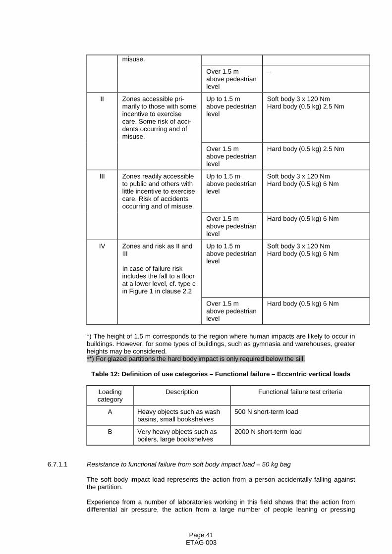
Page 41ETAG 003
misuse.
Over 1.5 mabove pedestrianlevel
–
II Zones accessible pri-marily to those with someincentive to exercisecare. Some risk of acci-dents occurring and ofmisuse.
Up to 1.5 mabove pedestrianlevel
Soft body 3 x 120 NmHard body (0.5 kg) 2.5 Nm
Over 1.5 mabove pedestrianlevel
Hard body (0.5 kg) 2.5 Nm
III Zones readily accessibleto public and others withlittle incentive to exercisecare. Risk of accidentsoccurring and of misuse.
Up to 1.5 mabove pedestrianlevel
Soft body 3 x 120 NmHard body (0.5 kg) 6 Nm
Over 1.5 mabove pedestrianlevel
Hard body (0.5 kg) 6 Nm
IV Zones and risk as II andIII
In case of failure riskincludes the fall to a floorat a lower level, cf. type cin Figure 1 in clause 2.2
Up to 1.5 mabove pedestrianlevel
Soft body 3 x 120 NmHard body (0.5 kg) 6 Nm
Over 1.5 mabove pedestrianlevel
Hard body (0.5 kg) 6 Nm
*) The height of 1.5 m corresponds to the region where human impacts are likely to occur inbuildings. However, for some types of buildings, such as gymnasia and warehouses, greaterheights may be considered.**) For glazed partitions the hard body impact is only required below the sill.
Table 12: Definition of use categories – Functional failure – Eccentric vertical loads
Loadingcategory
Description Functional failure test criteria
A Heavy objects such as washbasins, small bookshelves
500 N short-term load
B Very heavy objects such asboilers, large bookshelves
2000 N short-term load
6.7.1.1 Resistance to functional failure from soft body impact load – 50 kg bag
The soft body impact load represents the action from a person accidentally falling againstthe partition.
Experience from a number of laboratories working in this field shows that the action fromdifferential air pressure, the action from a large number of people leaning or pressing

Page 42ETAG 003
against the partition (crowd pressure) and the action from slamming of doors may usually beconsidered satisfactory if the partition resists the soft body impact load test.
Table 13: Assessment criteria for large soft body impact test
Use category Functional failure test criteria
I 3 x 60 NmMaximum deflection during impact to be reported
No functional failure*)Maximum residual deflection after 3 impacts 5 mm
The increase of deflection during testing shall stabilizeOpening of door still possible
II
3 x 120 Nm
III
IV*) The surface of the kit may not be damaged, however, impact marks are allowed
6.7.1.2 Resistance to functional failure from hard body impact load – 0.5 kg steel ball
The hard body impact load with the 0.5 kg steel ball represents the action from light non-deformable objects such as pieces of furniture or cleaning tools accidentally hitting thepartition when being moved.
Table 14: Assessment criteria for small hard body impact test
Use category Functional failure test criteria
I 1 x 2,5 Nm*)
Indentation marks to be reported, e.g. range of diametersNo functional failure**)
II 1 x 2,5 Nm*)
III 1 x 6 Nm*)
IV 1 x 6 Nm*)*) In 10 different positions**) The surface of the kit may not be damaged, however, impact marks are allowed
6.7.1.3 Resistance to functional failure from eccentric vertical load
The eccentric vertical load represents the action from heavy objects such as bookshelves orsanitary or heating equipment, supported primarily by the partition. Partitions may bemodified locally to fulfil the requirements provided the modifications form part of the systemand are fully described.
For partitions not designed to have a loadbearing capacity, other than for ordinarydecorations such as pictures, this requirement is not relevant and clause 6.7.1.4 shall beused.
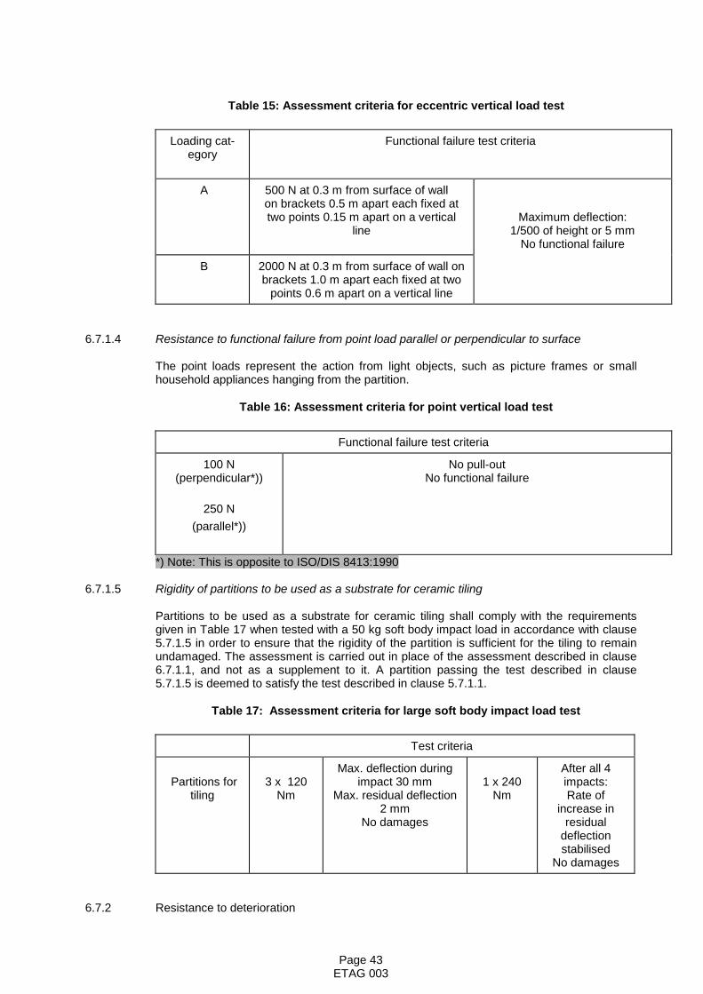
Page 43ETAG 003
Table 15: Assessment criteria for eccentric vertical load test
Loading cat-egory
Functional failure test criteria
A 500 N at 0.3 m from surface of wall on brackets 0.5 m apart each fixed attwo points 0.15 m apart on a vertical
lineMaximum deflection:
1/500 of height or 5 mmNo functional failure
B 2000 N at 0.3 m from surface of wall onbrackets 1.0 m apart each fixed at two
points 0.6 m apart on a vertical line
6.7.1.4 Resistance to functional failure from point load parallel or perpendicular to surface
The point loads represent the action from light objects, such as picture frames or smallhousehold appliances hanging from the partition.
Table 16: Assessment criteria for point vertical load test
Functional failure test criteria
100 N(perpendicular*))
250 N(parallel*))
No pull-outNo functional failure
*) Note: This is opposite to ISO/DIS 8413:1990
6.7.1.5 Rigidity of partitions to be used as a substrate for ceramic tiling
Partitions to be used as a substrate for ceramic tiling shall comply with the requirementsgiven in Table 17 when tested with a 50 kg soft body impact load in accordance with clause5.7.1.5 in order to ensure that the rigidity of the partition is sufficient for the tiling to remainundamaged. The assessment is carried out in place of the assessment described in clause6.7.1.1, and not as a supplement to it. A partition passing the test described in clause5.7.1.5 is deemed to satisfy the test described in clause 5.7.1.1.
Table 17: Assessment criteria for large soft body impact load test
Test criteria
Partitions fortiling
3 x 120Nm
Max. deflection duringimpact 30 mm
Max. residual deflection2 mm
No damages
1 x 240Nm
After all 4impacts:Rate of
increase inresidual
deflectionstabilised
No damages
6.7.2 Resistance to deterioration
Page 44ETAG 003
6.7.2.1 Physical agents
Hygrothermal conditions.
The difference in atmospheric conditions in the test described in clause 5.7.2.1 representsthose likely to occur due to different uses of partitions and the effect of adjacent spaces withdifferent conditions separated by the partition. Under any of these conditions, the deflectionof the partition shall not exceed the lesser of 1/500 of the height of the partition or 5 mm.
Deflections due to the following hygrothermal conditions:
– temporary (as in temperature and humidity increases in bathrooms or kitchens)
– exceptional (as in heavy frost)
– localised (as in radiation from the sun or heating)
will not exceed the lesser of 1/500 of the height of the partition or 5 mm.When tested in accordance with clause 5.7.2.1 relating to the effects of radiation, thepartition shall be checked to ensure that the properties of the partition have not beenimpaired (e.g. loss of adhesion, fracture, residual deflection).
6.7.2.2 Chemical agents
– Corrosion of steel components:
The product specification shall be examined to determine whether the protectionagainst corrosion is appropriate for the intended use.
Components made of steel sheet having a corrosion protection which at leastcorresponds to class Z275 as defined in EN 10326:2004 – Continuously hot-dip coatedstrip and sheets of structural steels – Technical delivery conditions are considered tofulfil the requirements.
– Cleaning agents:
The assessment of surfaces of materials of known composition and of knownperformance shall be given in qualitative terms.
6.7.2.3 Biological agents
The result of the assessment is examined and preventive measures or limitations in usedetermined. The partition’s susceptibility to infestation by insects and vermin is described.
– The conditions for attack by biological agents of components made of wood or wood-based panels, in general may be regarded as in hazard class 1 as defined in EN 335-1:1992 – Durability of wood and wood based products – Definition of hazard classes ofbiological attack – Part 1: General. This means that no treatment of such componentsis necessary. Certain wood or wood-based components, e.g. when fitted inindependent linings for exterior walls, may be exposed to conditions as in hazard class2 and, therefore, should be treated accordingly.
6.7.3 IDENTIFICATION OF THE PRODUCT
The results of the identification tests shall be declared.

Page 45ETAG 003
7. ASSUMPTIONS AND RECOMMENDATIONSunder which the fitness for use of the products is assessed
Chapter 7 sets out the preconditions for design, execution, maintenance and repair whichare a presumption for the assessment of the fitness for use according to the Guideline (onlywhen necessary and where they have a bearing on the assessment or on the products).
The issued European Technical Approvals shall state these conditions, where relevant.
7.1 DESIGN AND EXECUTION OF WORKS
The conditions for design and execution of the partition into the works shall be taken fromthe manufacturer's installation guide. The quality and sufficiency of this installation guideshall be assessed, in particular concerning the aspects on the following check list:
Design of joints between partition and main structure:
– permissible deflections of the adjacent structural parts– when appropriate, special fixings for seismic conditions;
in case of dynamic actions such as those occurring in case of earthquake, the designerhas to prevent the possibility of a structural contribution of the partition, by insertingrelevant joints between the partition and the frame, so that displacement of the framecan occur without interference of the partition. In case of absence of those joints, thedesigner shall take account of the possible contribution in accordance with national orlocal regulations.
Dimensional stability:
– relationship between the deflection per unit height and the hygrothermal conditionsacross the partition
Reduction of the risk of surface and interstitial condensation in the works:
– heating– ventilation– vapour control layer
Thermal resistance:
– cold bridges
Sound insulation:
– air paths through gaps, cracks, holes– flanking transmission– type of fixings
Infestation:
– sealing of voids– closure of small apertures
It shall be stated in the ETA that the installation guide forms part of the ETA and thus alwaysshall accompany the delivered system components. The ETA may take over the essentialparts of the installation guide.
The assessment of the fitness of use for relocatable partitions is based upon the assumption

Page 46ETAG 003
that in the process of dismantling and reassembly, the claimed characteristics areunaffected. This assumption may need to be verified.
7.2 MAINTENANCE AND REPAIR
The assessment of the fitness for use is based on the assumption that abrasions and minorimpact damage are inevitable and shall be capable of easy repair without causing adverseeffects.

Page 47ETAG 003
Section Three: ATTESTATION OF CONFORMITY (AC)
8 EVALUATION OF CONFORMITY
8.1 EC DECISION
The systems of attestation of conformity specified by the European Commission in mandateConstruct 98/213/EC, Annex 3 as amended, are as follows:
System 1 for partitions
- with Euroclasses A1*, A2*, B* or, C* concerning Reaction to fire, and for materials forwhich a clearly identifiable stage in the production process results in an improvement ofthe reaction to fire classification
System 3 for partitions
- with Euroclasses A1**, A2** , B**, C**, D, E concerning Reaction to fire, and formaterials not covered by system 1
- with any Fire resistance class
- for uses subject to regulations on dangerous substances
- with Safety in use category IV
System 4 for all other partitions, including partitions with Reaction to fire classes A1***(without testing according to EC Decision 96/603/EC) to E*** and F.
* Products/materials for which a clearly identified stage in the production, results in an improvement of the reactionto fire classification; (e.g. an addition of fire retardants or a limiting of organic material).** Products/materials not covered by footnote (*)*** Products/materials of class A1 that according to Decision 96/603/EC, amended by EC Decision 200/605/EC, donot require to be tested for reaction to fire.
The systems are described in Council Directive (89 /106/EEC) Annex III, 2(i), 2(ii) Secondpossibility and 2(ii) Third possibility, respectively, and are detailed as follows:
System 1
(a) Tasks for the manufacturer
- factory production control
- further testing of samples taken at the factory by the manufacturer in accordance with aprescribed test plan.
(b) Tasks for the approved body
- initial type-testing of the product
- initial inspection of the factory and of factory production control
- continuous surveillance, assessment and approval of factory production control.
System 3

Page 48ETAG 003
(a) Tasks for the manufacturer
– factory production control– initial type testing of the product by an approved laboratory
System 4
(a) Tasks for the manufacturer
– factory production control– initial type testing.
8.2 RESPONSIBILITIES
8.2.1 Tasks for the manufacturer
8.2.1.1 Factory production control
The manufacturer shall exercise permanent internal control of production. All the elements,requirements and provisions adopted by the manufacturer shall be documented in asystematic manner in the form of written policies and procedures. This production controlsystem shall ensure that the product is in conformity with the ETA.
Manufacturers having an FPC system which complies with EN ISO 9001 and whichaddresses the requirements of an ETA are recognized as satisfying the FPC requirementsof the Directive.
8.2.1.2 Testing of samples taken at the factory
Both large and small companies produce these products and there is a wide variation in thematerials used. Therefore a precise test plan can only be set up on a case by case basis.
In general it is not necessary to conduct tests on complete partitions. Indirect methods willnormally be sufficient, e.g. control of raw materials, manufacturing processes and propertiesof components.
8.2.1.3 Declaration of Conformity
When all the criteria of the Conformity Attestation are satisfied the manufacturer shall makea Declaration of Conformity.
8.2.2 Tasks for the manufacturer or the approved body
8.2.2.1 Initial Type Testing
Approval tests will have been conducted by the approval body or under its responsibility(which may include a proportion conducted by a laboratory or by the manufacturer,witnessed by the approval body) in accordance with section 5 of this ETAG. The approvalbody will have assessed the results of these tests in accordance with section 6 of thisETAG, as part of the ETA issuing procedure.
These tests shall be used for the purposes of Initial Type Testing. In this respect approvalbodies shall be able to have open arrangements with relevant approved bodies to avoidduplication, respecting each others responsibilities.System 1: this work shall be validated by the approved body for Certificate of Conformitypurposes.
System 3: this work shall be validated by an approved laboratory for Declaration ofConformity purposes by the manufacturer.
Page 49ETAG 003
System 4: this work should be taken over by the manufacturer for Declaration of Conformitypurposes.
8.2.3 Tasks for the approved body (System 1)
8.2.3.1 Assessment of the factory production control system - initial inspection and continuoussurveillance
Assessment of the factory production control system is the responsibility of the approvedbody.
An assessment must be carried out of each production unit to demonstrate that the factoryproduction control is in conformity with the ETA and any subsidiary information. Thisassessment shall be based on an initial inspection of the factory.
Subsequently continuous surveillance of factory production control is necessary to ensurecontinuing conformity with the ETA.
It is recommended that surveillance inspections be conducted at least twice per year.
8.2.3.2 Certification of Conformity
The approved body shall issue Certification of Conformity of the product.
8.3 DOCUMENTATION
In order to help the approved body make an evaluation of conformity the approval bodyissuing the ETA shall supply the information detailed below. This information together withthe requirements given in EC Guidance Paper B will:
System 1: generally form the basis on which the factory production control (FPC) isassessed by the approved body
System 3 andSystem 4: generally form the basis of FPC.
This information shall initially be prepared or collected by the approval body and shall beagreed with the manufacturer. The following gives guidance on the type of informationrequired:
(1) The ETA
See section 9 of this Guideline.
The nature of any additional (confidential) information shall be declared in the ETA.
(2) Basic manufacturing process
The basic manufacturing process shall be described in sufficient detail to support theproposed FPC methods.
Components for partitions are normally manufactured using conventional techniques.Any critical process or treatment of the components affecting performance shall behighlighted.
(3) Product and materials specifications
These may include:
detailed drawings (including manufacturing tolerances)

Page 50ETAG 003
incoming (raw) materials specifications and declarationsreferences to European and/or international standards or appropriate specificationsmanufacturer’s data sheets.
(4) Test plan
The manufacturer and the approval body issuing the ETA shall agree an FPC test plan.
An agreed FPC test plan is necessary as current standards relating to qualitymanagement systems (Guidance Paper B etc), do not ensure that the productspecification remains unchanged and they cannot address the technical validity of thetype or frequency of checks/tests.
The validity of the type and frequency of checks/tests conducted during production andon the final product shall be considered. This will include the checks conducted duringmanufacture on properties that cannot be inspected at a later stage and for checks onthe final product. These will normally include:
material propertiesdimensions of component parts
Where materials/components are not manufactured and tested by the supplier inaccordance with agreed methods, then where appropriate they must be subject tosuitable checks/tests by the manufacturer before acceptance.
(5) Prescribed test plan (System 1)
The manufacturer and the approval body issuing the ETA shall agree a prescribed testplan.
The characteristic to be addressed as described in the mandate is Reaction to fire.This will be controlled at least twice per year by analysis/measurement of the relevantcharacteristics for the components of the kit from the following list:
compositiondimensionsphysical propertiesmechanical propertiesconstruction.
8.4 CE MARKING AND INFORMATION
The ETA shall indicate the information to accompany the CE marking and the placement ofCE marking and the accompanying information (the kit/components itself/themselves, anattached label, the packaging, or the accompanying commercial documents).
According to the CE Guidance Paper D on CE marking, the required information toaccompany the symbol “CE” is:
– identification number of the notified body (System 1)– name or identifying mark of the producer– last two digits of the year in which the marking was affixed– number of the EC certificate of conformity (System 1)– number of the ETA (valid as indications to identify the characteristics of the partition kit
and the characteristics where the “no performance determined” approach is used)– ETAG no. 003.

Page 51ETAG 003
Section Four: ETA CONTENT
9 THE ETA CONTENT
9.1 THE ETA CONTENT
9.1.1 Model ETA
The ETA content shall be in accordance with the Commission Decision 97/571/EC, dated 22July 1997.
In section II.2 “characteristics of products and methods of verification “ the ETA shall includethe following note:
In addition to the specific clauses relating to dangerous substances contained in thisEuropean Technical Approval, there may be other requirements applicable to the productsfalling within its scope (e.g. transposed European legislation and national laws, regulationsand administrative provisions). In order to meet the provisions of the EU ConstructionProducts Directive, these requirements need also to be complied with, when and where theyapply.
9.1.2 Checklist for the issuing body
The technical part of the ETA shall contain information on the following items, in the orderand with reference to the relevant 5 Essential Requirements. For each of the listed items,the ETA shall either give the mentioned indication/classification/statement/description orstate that the verification/assessment of this item has not been carried out. The items arehere given with reference to the relevant clause of this guideline:
– Indication of the assumed working life (Section Two, introduction)
– Classification of the components of the kit with respect to reaction to fire, including testmethod used (Clause 6.2.1)
– Classification of partition with respect to fire resistance, including test method used(Clause 6.2.2)
– Statement on the presence and concentration/emission rate/etc. of formaldehyde,asbestos, pentachlorophenol, other dangerous substances or statement on nopresence of dangerous materials (Clause 6.3.1)
– Indication of water vapour permeability of materials (Clause 6.3.2)
– Statement that condensation in the partition as a result of water vapour diffusion willnot occur or will occur only to an extent where damage is not caused during thecondensation period and the partition will dry out again during the evaporation period(Clause 6.3.2)
– Statement on the most severe use application for structural damage and functionalfailure for impact loads for which the system has been assessed (use category no,including description) and the test methods used including the energies of the impacttest regime performed to verify the above statement (Clause 6.4.1.1, 6.4.1.2, 6.7.1.1and 6.7.1.2)
– Information on the maximum deflection during impact in the test of resistance tofunctional failure from soft body impact load, with an indication of the height of the testspecimen and the energy level used (Clause 6.7.1.1)
Page 52ETAG 003
– Statement on the most severe use application for structural damage and functionalfailure for eccentric vertical loads for which the system has been assessed (loading usecategoty a or b, including description) and the test methods used (Clause 6.4.1.3 and6.7.1.3)
– Indication of possible reinforcements to improve resistance against eccentric verticalload (Clause 6.4.1.3)
– Indication of the equivalent characteristic resistance to horizontal static linear load,including the recommended load factor and deflections at 25 mm and 40 mm (Clause6.4.1.4)
– Description of the nature of the surface (Clause 6.4.2)
– Indication of measured airborne sound insulation, including the test method used(Clause 6.5.1)
– Indication of measured sound absorption coefficient, including the test method used(Clause 6.5.2)
– Indication of calculated or measured thermal resistance, including the calculation ortest method used (Clause 6.6.1)
– Indication of relevant properties for the calculation of the contribution to the thermalinertia of the works (Clause 6.6.2)
– Indication of result from point load resistance test, including test method (Clause6.7.1.4)
– Indication of results from rigidity test, including test method (Clause 6.7.1.5)
– Indication of resistance to hygrothermal conditions, including test method, if used(Clause 6.7.2.1)
– Indication of resistance to corrosion (Clause 6.7.2.2 )
– Indication of resistance to cleaning, including test method, if used (Clause 6.7.2.2)
– Indication of resistance to biological agents (Clause 6.7.2.3).
9.2 ADDITIONAL INFORMATION
It shall be stated in the ETA if the manufacturer’s installation guide forms part of the ETA,see clause 7.1 of this Guideline.
Similarly, it shall be stated in the ETA whether or not any additional (possibly confidential)information shall be supplied to the approved body for the evaluation of conformity, seeclause 8.3 of this Guideline.
If doors are included in the kit, the available width and height shall be stated.If the kit includes large areas of transparent glazing, the means by which it is marked to avoidpersons colliding with it shall be stated.
Page 53ETAG 003
Annex A(Definitions, clarifications and abbreviations)
1. WORKS AND PRODUCTS
1.1 Construction works (and parts of works) (often simply referred to as "works") (ID 1.3.1)Everything that is constructed or results from construction operations and is fixed to the ground.(This covers both building and civil engineering works, and both structural and non structural elements).
1.2. Construction products (often simply referred to as "products") (ID 1.3.2)Products which are produced for incorporation in a permanent manner in the works and placed as such on themarket.(The term includes materials, elements and components of prefabricated systems or installations)
1.3. Incorporation (of products in works) (ID 1.3.2)Incorporation of a product in a permanent manner in the works means that:- its removal reduces the performance capabilities of the works, and- that the dismantling or the replacement of the product are operations which involve construction activities.
1.4. Intended use (ID 1.3.4)Role(s) that the product is intended to play in the fulfillment of the essential requirements.(N.B. This definition covers only the intended use as far as relevant for the CPD)
1.5. Execution (ETAG-format)Used in this document to cover all types of incorporation techniques such as installation, assembling,incorporation, etc.
1.6. System (EOTA/TB guidance)Part of the works realised by- particular combination of a set of defined products, and- particular design methods for the system, and/or- particular execution procedures.
2. PERFORMANCES
2.1. Fitness for intended use (of products) (CPD 2.1)Means that the products have such characteristics that the works in which they are intended to be incorporated,assembled, applied or installed, can, if properly designed and built, satisfy the essential requirements.(N.B. This definition covers only the intended fitness for intended use as far as relevant for the CPD)
2.2. Serviceability (of works)Ability of the works to fulfill their intended use and in particular the essential requirements relevant for this use.
The products must be suitable for construction works which (as a whole and in their separate parts) are fit fortheir intended use, subject to normal maintenance, be satisfied for an economically reasonable working life. Therequirements generally concern actions which are foreseeable (CPD Annex I, Preamble).
2.3. Essential requirements (for works): requirements applicable to works, which may influence the technicalcharacteristics of a product, and are set out in terms of objectives in the CPD, Annex I (CPD, art. 3.1).
2.4. Performance (of works, parts of works or products) (ID 1.3.7)The quantitative expression (value, grade, class or level) of the behaviour of the works, parts of works or of theproducts, for an action to which it is subject or which it generates under the intended service conditions (worksor parts of works) or intended use conditions (products).
Page 54ETAG 003
As far as practicable the characteristics of products, or groups of products, should be described in measurableperformance terms in the technical specifications and guidelines for ETA. Methods of calculation, measurement,testing (where possible), evaluation of site experience and verification, together with compliance criteria shall begiven either in the relevant technical specifications or in references called up in such specifications.
2.5. Actions (on works or parts of the works) (ID 1.3.6)Service conditions of the works which may affect the compliance of the works with the essential requirements ofthe Directive and which are brought about by agents (mechanical, chemical, biological, thermal or electro-magnetic) acting on the works or parts of the works.Interactions between various products within a work are considered as "actions".
2.6. Classes or levels (for essential requirements and for related product performances) (ID 1.2.1)A classification of product performance(s) expressed as a range of requirement levels of the works, determinedin the ID's or according to the procedure provided for in art. 20.2a of the CPD.
3. ETAG - FORMAT
3.1. Requirements (for works) (ETAG-format 4.)Expression and application, in more detail and in terms applicable to the scope of the guideline, of the relevantrequirements of the CPD (given concrete form in the ID's and further specified in the mandate, for works orparts of the works, taking into account the durability and serviceability of the works.
3.2. Methods of verification (for products) (ETAG-format 5.)Verification methods used to determine the performance of the products in relation to the requirements for theworks (calculations, tests, engineering knowledge, evaluation of site experience, etc.).
This verification methods are related only to the assessment of, and for judging the fitness for use. Verificationmethods for particular designs of works are called here "project testing", for identification of products are called"identification testing", for surveillance of execution or executed works are called "surveillance testing", and forattestation of conformity are called "AC-testing".
3.3. Specifications (for products) (ETAG-format 6.)Transposition of the requirements into precise and measurable (as far as possible and proportional to theimportance of the risk) or qualitative terms, related to the products and their intended use. The satisfaction of thespecifications is deemed to satisfy the fitness for use of the products concerned.
Specifications may also be formulated with regard to the verification of particular designs, for identification ofproducts, for surveillance of execution or executed works and for attestation of conformity, when relevant.
4. WORKING LIFE
4.1. Working life (of works or parts of the works) (ID 1.3.5(1)The period of time during which the performance will be maintained at a level compatible with the fulfilment ofthe essential requirements.
4.2. Working life (of products)Period of time during which the performances of the product are maintained - under the corresponding serviceconditions - at a level compatible with the intended use conditions.
4.3. Economically reasonable working life: (ID 1.3.5(2)Working life which takes into account all relevant aspects, such as costs of design, construction and use, costsarising from hindrance of use, risks and consequences of failure of the works during its working life and cost ofinsurance covering these risks, planned partial renewal, costs of inspections, maintenance, care and repair,costs of operation and administration, of disposal and environmental aspects.
4.4. Maintenance (of works) (ID 1.3.3(1)
Page 55ETAG 003
A set of preventive and other measures which are applied to the works in order to enable the works to fulfil all itsfunctions during its working life. These measures include cleaning, servicing, repainting, repairing, replacingparts of the works where needed, etc.
4.5. Normal maintenance (of works) (ID 1.3.3(2)Maintenance, normally including inspections, which occurs at a time when the cost of the intervention which hasto be made is not disproportionate to the value of the part of the work concerned, consequential costs (e.g.exploitation) being taken into account.
4.6. Durability (of products)Ability of the product to contribute to the working life of the work by maintaining its performances, under thecorresponding service conditions, at a level compatible with the fulfilment of the essential requirements by theworks.
5. CONFORMITY
5.1. Attestation of conformity (of products)Provisions and procedures as laid down in the CPD and fixed according to the directive, aiming to ensure that,with acceptable probability, the specified performance of the product is achieved by the ongoing production.
5.2. Identification (of a product)Product characteristics and methods for their verification, allowing to compare a given product with the one thatis described in the technical specification.
6. APPROVAL AND APPROVED BODIES
6.1. Approval BodyBody notified in accordance with Article 10 of the CPD, by an EU Member State or by an EFTA State(contracting party to the EEA Agreement), to issue European Technical Approvals in (a) specificconstruction product area(s). All such bodies are required to be members of the European Organisationfor Technical Approvals (EOTA), set up in accordance with Annex II.2 of the CPD.
6.2. Approved Body(*)Body nominated in accordance with Article 18 of the CPD, by an EU Member State or by an EFTA State(contracting party to the EEA Agreement) , to perform specific tasks in the framework of the Attestation ofConformity decision for specific construction products (certification, inspection or testing). All such bodiesare automatically members of the Group of Notified Bodies.
(*) also known as Notified Body

Page 56ETAG 003
ABBREVIATIONSConcerning the Construction products directive:
AC: Attestation of conformityCEC: Commission of the European CommunitiesCEN: Comité européen de normalisation / European Committee for StandardizationCPD: Construction products directiveEC: European communitiesEFTA: European free trade associationEN: European standardFPC: Factory production controlID: Interpretative documents of the CPDISO: International standardisation organisationSCC: Standing committee for construction of the EC
Concerning approval:
EOTA: European organisation for technical approvalsETA: European Technical ApprovalETAG: European technical approval guidelineTB: EOTA-Technical BoardUEAtc: Union européenne pour l’agrément technique / European union of agrément
General:TC: Technical committeeWG: Working group

Page 57ETAG 003
Annex BList of reference documentsSorted by numbers
Number Title
Commission Decision 96/603/EC
EN 120: 1994 Wood based panels – Determination of formaldehyde content – Extractionmethod called the perforator method
EN/ISO 140-3: 1995 Acoustics - Measurement of sound insulation in buildings and of buildingelements - Part 3: Laboratory measurements of airborne sound insulation ofbuilding elements
EN 300: 1997 Oriented Strand Boards (OSB) – Definitions, Classification and Specifications
EN 312-1: 1997 Particleboards – Specifications – Part 1: General Requirements for all BoardTypes
EN 335-1: 1992 Durability of wood and wood-based products - Definition of hazard classes ofbiological attack - Part 1: General
EN ISO 354: 2003 Acoustics – Measurement of sound absorption in a reverberation room
EN 423: 2002 Resilient floor coverings – Determination of the effect of stains
EN 622-5: 1997 Fibreboards – Specifications – Part 5: Requirements for Dry Process Boards(MDF)
EN 636-3: 1997 Plywood – Specifications – Part 3: Requirements for Plywood for Use inExterior Conditions
EN 636-2: 1997 Plywood – Specifications – Part 2: Requirements for Plywood for Use in HumidConditions
EN 636-1: 1997 Plywood – Specifications – Part 1: Requirements for Plywood for Use in DryConditions
EN/ISO 717-3: 1997 Wood-based panels – Determination of formaldehyde release – Part 3:Formaldehyde release by the flask method
EN/ISO 717-2/AC: 2002 Wood-based panels – Determination of formaldehyde release – Part 2:Formaldehyde release by the gas analysis method
EN/ISO 717-1: 1996 Acoustics – Rating of sound insulation in buildings and of building elements.Part 1 – Airborne sound insulation
EN 1991-1-1: 2002 Eurocode 1: Basis of design and actions on structures – Part 2-1: Actions onstructures – Densities, self-weight and imposed loads
EN/ISO 6946: 1997 Building components and building elements - Thermal resistance and thermaltransmittance - Calculation method
ISO 7892: 1988 Vertical Building Components - Impact resistance - Impact Bodies and GeneralTest Procedures
ISO/DIS 7893: 1990 Performance Standards in Building - Partitions made from Components -Impact resistance tests
ISO/DIS 8413: 1990 Performance Standards in Building - Partitions made from Components - Testsfor Ability to withstand Suspended Static Loads
EN/ISO 8990: 1997 Thermal insulation - Determination of thermal resistance by means of guardedhot plate and heat flow meter methods - Calibrated and guarded hot box
EN/ISO 9001: 2000 Quality Management Systems – Requirements
EN/ISO 10211-2: 1995 Thermal bridges in building constructions – Part 2: Heat flows and surface

Page 58ETAG 003
temperatures – General calculation of linear thermal bridges
EN/ISO 10211-1: 1995 Thermal bridges in building constructions – Part 1: Heat flows and surfacetemperatures – General calculation methods
EN 10326:2004 Continuously hot-dip coated strip and sheets of structural steel – Technicaldelivery conditions
EN ISO 11654: 1997 Acoustics – Sound absorbers for use in buildings – Rating of sound absorption
ISO/DIS 12055 Building construction – Guardrail systems and rails for buildings
EN 12086:1999 Thermal performance of buildings and building components – Determination ofwater vapour transmission properties
EN 12524: 2001 Building materials and products. Hygrothermal properties. Tabulated designvalues
EN/ISO 12572: 2001 Hygrothermal performance of building materials and products – Determinationof water vapour transmission properties
EN 12667: 2001 Building materials - Determination of thermal resistance by means of guardedhot plate and heat flow meter methods - Products of high and medium thermalresistance
EN 12939: 2001 Building materials - Determination of thermal resistance by means of guardedhot plate and heat flow meter methods - Thick products of high and mediumthermal resistance
EN 13501-2 Fire resistance - Building Elements – Classification
EN 13501-1: 2002 Reaction to fire – Classification
EN/ISO 13788: 2001 Hygrothermal performance of building components and building elements -Estimation of internal surface temperature to avoid critical surface humidity andcalculation of interstitial condensation
EN 13823: 2002 Building products excluding floorings exposed to the thermal attack by a SingleBurning Item
EN 13986: 2002 Wood-based panels for use in construction - Characteristics, evaluation ofconformity and marking

Page 59ETAG 003
Annex C
C INTERNAL PARTITION KITS – RESISTANCE TO IMPACT LOADS AND SUSPENDEDVERTICAL LOADS – GENERAL
C.1 General
The testing shall be carried out on sample partitions representative of those to be suppliedand/or erected in practice fitted into an appropriate test rig. Whenever possible theinstallation of the test sample shall be carried out by the sponsor of the test.
The test methods used are ISO methods but certain elements are modified or amended.
Unless otherwise stated in the test methods, loads and forces shall be accurate to within ±2%, dimensions to within ± 1%, temperatures to within ± 5°C and relative air humidities towithin ± 5% of the stated values.
C.2 Partition sample
The selection of the sample needs careful consideration to ensure that it fully represents thepartition kit. Normally, the sample shall be a production partition fabricated in strictaccordance with the manufacturer’s drawings, specifications and installation instructions.
As a general rule, the highest partition in the range should be tested as this will tend to bethe weakest and, therefore, will allow partitions of a lesser height to be assessed as being atleast as good. However, several specimens may need to be tested to gain information aboutthe full range of options available for a given system, for example full height and partialglazing, changes to member size throughout the range, thicknesses, detailing at junctionsand corners and inclusion of all necessary features. The number and position of discretefixings between panels and discrete members shall also be considered.
The principles of the sample are described in ISO draft standard ISO/DIS 7893:1990. Thesample shall be a straight run of partition (see Figure 1) and should fully reflect the partitionsystem including all necessary fittings and fixings complete with joints at the top, bottom,end and intermediate positions. The partition sample should include all integral components,such as glazing, which may have a detrimental effect on the performance levels achieved. Ifthe test sample does not include a door-set belonging to the partition system, a type of door-set commonly used in the type of partition system being tested should be fitted in theopening. The door-set should be installed as shown in Figure 2. The door opens towards theobserver.
The total length of the sample shall be at least 4.5 m. It shall include at least 3.0 m ofstraight partition, an opening at least 800 mm wide for fixing a doorset and at least 600 mmof partition flanking the other side of the opening (see Figure 1). For modular partitionsystems, standard modules shall be used, even if the above dimensions are exceeded. The3 m of straight partition shall consist of at least three modules.
The test rig should allow for the fixing of a corner piece or corner element to the free end ofthe sample for the possible testing of corner trim details, cf. Annex D2.
The height of the sample shall be that set by the manufacturer. The test rig for testinginternal partitions for ceramic tiling shall be at least 2600 mm high.
In case of variations of the basically same kit, additional tests can be performed on smallertest samples.

Page 60ETAG 003
The way in which components are fixed to each other shall reproduce actual conditions ofuse, particularly with respect to the nature, type and position of the fixings and the distancebetween them.
Figure 2 - Partition sample dimensions
C.3 Conditioning
The sample conditioning shall be recorded. The conditioning period shall be agreed betweenthe sponsor and the test authority.
C.4 Sequence of tests
Testing to determine a class can for example follow the sequence given below.
C.4.1 Hard body impact load – 0.5 kg steel ball – Functional failure test
C.4.2 Eccentric vertical load – Functional failure test
C.4.3 Soft body impact load – 50 kg bag – Functional failure test
C.4.4 Eccentric vertical load – Structural damage test
C.4.5 Hard body impact load – 1 kg steel ball – Structural damage test
C.4.6 Soft body impact load – 50 kg bag – Structural damage test.
For partitions to be used as a substrate for ceramic tiling, test C.5.3 in the test sequence is replaced bythe test described in Annex E.
Page 61ETAG 003
Annex DD INTERNAL PARTITION KITS – RESISTANCE TO IMPACT LOADS, SUSPENDED
VERTICAL LOADS AND HORISONTAL LINEAR STATIC LOADS– TEST METHODS
D.1 Hard body impact load – 0.5 kg steel ball
ISO 7892:1988, Vertical Building Components – Impact Resistance – Impact Bodies andGeneral Test Procedures and ISO/DIS 7893:1990, Performance Standards in Building –Partitions made from Components – Impact Resistance Tests.
ISO/DIS 7893:1990 is subject to the modifications to sample construction shown in AnnexC.
The load shall be applied at least ten times, each time in a new position, at various heightsin areas considered to be weak.
The diameter of any indentation shall be reported. Note shall be made of any damagecaused.
D.2 Hard body impact load – 1 kg steel ball
ISO 7892:1988, Vertical Building Components – Impact Resistance – Impact Bodies andGeneral Test Procedures and ISO/DIS 7893:1990, Performance Standards in Building –Partitions made from Components – Impact Resistance Tests.
ISO/DIS 7893:1990 is subject to the modifications to sample construction shown in Annex Cincluding the weight of the impact body.
The impact may need to be repeated at various points on the same element if the weakestpoint is not obvious.
When testing corner details mounted at the free end of the partition sample, it may becomenecessary to support (fix) it.
The diameter of any indentation shall be reported. Note shall be made of any damagecaused.
D.3 Soft body impact load – 50 kg bag
D.3.1 General
The soft body impact load – 50 kg bag is used for the determination of the followingproperties of the internal partition:
• Resistance to functional failure from a soft body impact load – 50 kg bag;• Resistance to structural damage from a soft body impact load – 50 kg bag;• Rigidity of partitions to be used as substrate for ceramic tiling (this item is being
covered by Annex E).
The test procedure to be followed is according «ISO 7892:1988, Vertical BuildingComponents – Impact Resistance – Impact Bodies and General Test Procedures»
The test is carried out according «ISO/DIS 7893:1990 , Performance Standards in Building-Partitions made from Components-Impact Resistance Tests», taking into account theamendments and modifications described in this annex.
Page 62ETAG 003
General condition during the test.The door should remain closed during the impact resistance test.
D.3.2 General Resistance to functional failure from soft impact load – 50 kg bag.
For the determination of the resistance of the internal partition to functional failure load thefrontal displacement is to be measured.For this reason a deflection transmitter shall be fixed to the back of the test sampleimmediately opposite the point of impact.
D.3.2.1 Points of impact.
The points of impact to be used in the test are depending on the composition of the partition.
D.3.2.1.1 Non homogenous partitions
Non homogenous partitions according this guideline are characterized by a frameconstruction, using horizontal and/or vertical elements such as studs.The area of impact is not as shown in Figure 3 of ISO/DIS 7893:1990.The points of impact shall be chosen along a straight line at a height (H3) of 1.5 m above theground unless this interferes with a horizontal member in the frame construction of thepartition sample. In this case it may vary between 1.2 m and 1.7 m from the grounddepending on what results in the greater distance from the underlying frame construction.
The functional failure impacts are carried out both on studs and between studs, each byapplying a series of 3 impacts at the same point of impact. (in case of partitions to be usedas substrate for ceramic tiling: 3 impacts of 120 Nm and 1 impact of 240 Nm, see annex E).
Additionally one series is carried out with the centre of impact at 150 mm from door opening.
The maximum deflection during each impact and the residual deflection after each impactshall be reported. The residual deflection shall be measured five minutes after the impact.Note shall be made of any damage caused and of the operating condition of the door.
D.3.2.1.2 Homogenous partitions.
As homogenous partitions according this guideline are considered all other partitions thatare not covered by D.3.2.1.1.The area of impact is not as shown in Figure 3 of ISO/DIS 7893:1990.The points of impact shall be chosen along a straight line at a height (H’2) of 1.5 m abovethe groundThe functional failure impacts are carried at least on two different points of impact, each byapplying a series of 3 impacts at the same point of impact. (in case of partitions to be usedas substrate for ceramic tiling: 3 impacts of 120 Nm and 1 impact of 240 Nm).
Additionally one series is carried out with the centre of impact at 150 mm from door opening.
The maximum deflection during each impact and the residual deflection after each impactshall be reported. The residual deflection shall be measured five minutes after the impact.Note shall be made of any damage caused and of the operating condition of the door.
D.3.3 Resistance to structural damage from soft body impact load – 50 kg bag.
Both non homogenous partitions and homogenous partitionsThe structural damage impact is carried out at a new point and this should be the weakestpart of the partition system. The point of impact shall be chosen along a straight line at aheight (H’2) of 1.5 m above the ground.The impact may need to be repeated if the weakest point is not obvious.
Page 63ETAG 003
Note shall be made of any damage caused (penetration, collapse or other dangerousfailure).
D.4 Eccentric vertical load
Draft ISO 8413:1990, Performance Standards in Building – Partitions made fromComponents Tests for Ability to withstand Suspended Static Loads.
Loading Category A is as in clause 7.2 of the standard.
Loading Category B is as in clause 7.2 of the standard but the fixing points are 1 m apart,each fixed at 2 positions 0.6 m apart on vertical lines.
The fixings are located in the middle of the test specimen, unless otherwise specified by themanufacturer.
Loads shall be applied and removed at a rate of approximately 2000 N/min. When therelevant load level for functional failure load (i.e. 500 N or 2000 N) have been reached, themeasurement is taken and the load is then removed. The load shall not remain betweenapplication and removal. Structural damage loads (i.e. 1000 N or 4000 N) shall remain for24 hours between application and removal. Measurements are taken at sufficient intervals.
The maximum deflection under load and the residual deflection shall be reported. Note shallbe made of any damage caused.
As an alternative, eccentric vertical loads according to specific requirements related to theloads to be applied in practice may be carried out. This may require different fixing centresand loads and should be carried out at the request of the manufacturer.
D.5 Horizontal static linear load
ISO/DIS 12055 Building and construction – Guardrail systems and rails for building,application of horizontal static uniformly distributed load, subject to the followingmodifications.
Of annex A only chapter A.1 – A.10 are relevant.
A.6.3 Specimen description:
The sample shall be a straight run of partition and should fully reflect the partition systemincluding all necessary fittings and fixings complete with joints at the top, bottom andintermediate positions. The ends (free edges) shall be free. The partition sample shouldinclude all integral components, such as glazing, which may have a detrimental effect on theperformance levels achieved.
The total length of the sample shall be at least 2 m. For modular partition systems, standardmodules shall be used, even if the above dimension is exceeded. The 2 m of straightpartition shall consist of at least two modules.
The height of the sample shall be that set by the manufacturer.
A.8 Failure analysis
The equivalent to a characteristic resistance to horizontal linear static load of the kit iscalculated by dividing the maximum load (failure or deflection 40 mm) reached in the test bya load factor of 2 - 5 (the factor depends on failure mode and/or material and shall berecommended by the approval body).
A.10.2 Procedure
The load shall be applied over the full length of the sample and at a height of 1,1 m or – if

Page 64ETAG 003
the kit is equipped with an integral member, e.g. transom, frame – at the height of theguardrail.
The load at which serviceability is compromised or at a maximum of 25 mm deflection isreported
The load at failure or at a maximum of 40 mm deflection is reported and used in the failureanalysis
The test is carried out once.
Page 65ETAG 003
Annex EE INTERNAL PARTITION KITS TO BE USED AS A SUBSTRATE FOR CERAMIC TILING
E.1 Partition Sample
The sample shall be as described in annex C
The sample shall be a straight run of partition. The length of the sample shall be at least3000 mm and at least 3 modules. The height of the sample shall be that set by themanufacturer but not less than 2600 mm. The sample shall be without fitting of the ceramictiling.
E.2 Conditioning
The sample conditioning shall be recorded. The conditioning period shall be agreed betweenthe manufacturer and the testing laboratory.
E.3 Apparatus
The load shall be applied by means of a 50 kg soft body in accordance with ISO 7892:1988, Vertical Building Components – Impact Resistance – Impact Bodies and General TestProcedures.
The deflection transmitter shall be fixed to the back of the test sample as close to the pointof impact as necessary for accurately measuring the movement of the surface behind thepoint of impact. For partitions of panels on a frame structure this means to the back of frontpanel(s), if necessary through an opening in the panel(s) on the back of the partition sample.
E.4 Test
The centre of impact shall be halfway between two studs horizontally and at half height ofthe partition sample above the ground vertically. If this interferes with horizontal members inthe frame construction, it shall be lowered to a height that produces the greatest distance tothe underlying frame construction, but not less than 1200 mm above ground.
The centre of impact shall remain the same for all four impacts.
The maximum deflection during each impact and the residual deflection after each impactshall be reported. Note shall be made of any damage caused.

Page 66ETAG 003
Annex F
F Internal Partition Kits – Test Reports
F.1 Test report
The test report shall include the information required for the particular test and the followingparticulars:
a number and date of this ETA Guideline and the title of the test.
b name and address of the test organisation
c name and address of the sponsor of the test and/or the producer of the system
d name or brief descriptive title of the partition system
e test reference letter and a cross reference to other tests carried out as part of asequence of tests and the order in which these tests were carried out either prior to orsubsequent to the individual tests
f dates of construction and tests
g dimensions and details of the partition sample, including modifications for theheavyweight anchorage tests that remain during other tests, method of fixing to the rigand fully detailed specifications and drawings
h description with diagram of the test rig and apparatus together with calibrationcertificates
i range of temperature and relative humidity in the laboratory during the installation,conditioning and testing and the period of conditioning.
F.2 Summary of test results
When more than one requirement has been tested, the test results shall be summarisedshowing whether the individual requirements tested passed a particular performance level.
If a use category, satisfying the requirements described in clauses 6.4.1 and 6.7.1 of theGuideline, has been achieved this shall be given in the summary of test results.

Page 67ETAG 003
Annex G
EN 13823: Reaction to fire tests for building products – Building productsexcluding floorings exposed to the thermal attack by a single burning item
Mounting and fixing provisions
G.1 Terminology
Module:A sample of the kit fully reflecting all components (e.g. board, frame, insulation, fasteners etc.) in the kitcut to fit the size of the test rig.
Extended application:The outcome of a process (involving the application of defined rules that may incorporate calculationprocedures) that predicts, for a variation of a product property and/or its intended use application(s), a testresult on the basis of one or more tests to the same test standard.
G.2 Mounting and fixing in accordance with EN 13823
G.2.1 Dimensions of the test rig
The test rig consists of a corner with a long (1,0 m) and a short (0,5 m) wing. The long wing consists of 2modules, with one vertical and one horizontal module-to-module joint in between. All modules shall betested vertically. The dimensions of the specimens shall be:
Assembly dimensions (mm – nominally)
Length Height
Short wing 495 1500
200 + t 1500Long wing (seefigure G1) 800 - t 1500
Where t = thickness of the kit
G.2.2 Test specimen
The internal partition kit shall be mounted and fixed according to EN 13823.
The test specimen shall fully represent all the envisaged components in the end use condition asspecified by the applicant. The external surface of the kit used in the test assembly shall always include allfacings and/or coatings that are applied to the product, as placed on the market. Each facing and/orcoating shall be considered but extended application rules shall apply, using regrouping in families.
Influences of different colours of facings or coatings can be determined by performing tests on a light, ona dark and on a colour in the middle of the range.
The assembly including corner and joint details shall be as specified by the applicant and in accordancethe end use conditions. Where several corner and jointing materials/profiles are foreseen, possibleextended application rules may apply.
Where the kit consists of boards on a frame, the largest frame thickness (perpendicular to the face)envisaged shall be used in the test. Test performed on timber framework also apply for metal framework.Where the applicant claims a better performance with a metal frame or where the applicant does not use
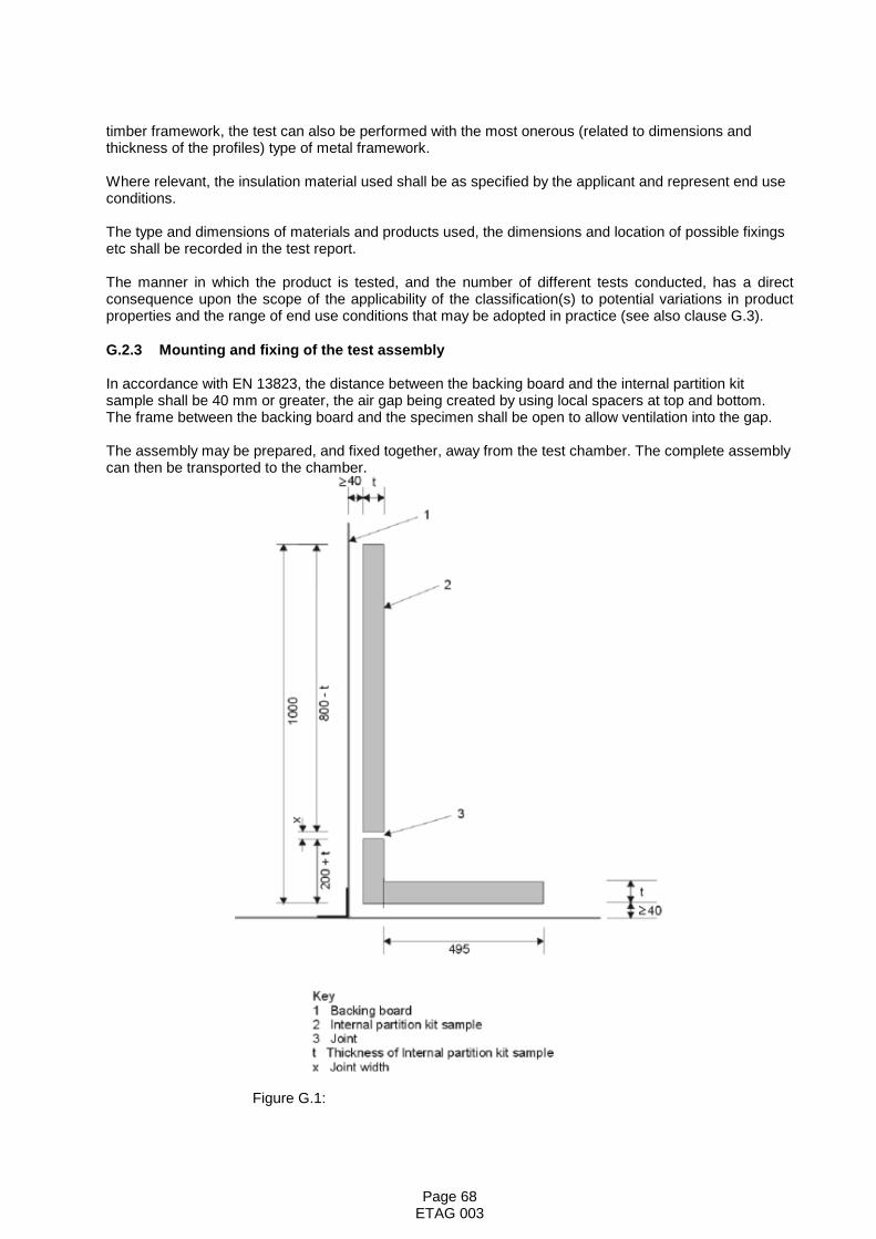
Page 68ETAG 003
timber framework, the test can also be performed with the most onerous (related to dimensions andthickness of the profiles) type of metal framework.
Where relevant, the insulation material used shall be as specified by the applicant and represent end useconditions.
The type and dimensions of materials and products used, the dimensions and location of possible fixingsetc shall be recorded in the test report.
The manner in which the product is tested, and the number of different tests conducted, has a directconsequence upon the scope of the applicability of the classification(s) to potential variations in productproperties and the range of end use conditions that may be adopted in practice (see also clause G.3).
G.2.3 Mounting and fixing of the test assembly
In accordance with EN 13823, the distance between the backing board and the internal partition kitsample shall be 40 mm or greater, the air gap being created by using local spacers at top and bottom.The frame between the backing board and the specimen shall be open to allow ventilation into the gap.
The assembly may be prepared, and fixed together, away from the test chamber. The complete assemblycan then be transported to the chamber.
Figure G.1:

Page 69ETAG 003
G3. End Use Application
When determining the testing programme all potential variations in product properties and in its potentialend-use condition need to be considered. For this type of construction product, the following providesguidance on the potential end-use application rules that may apply dependant on the testing programmeundertaken.
G3.1 Influence in thickness of the lining boards
If the reaction to fire classification of the partition is given as Class B, s1-d0 or worse then the influence ofincreased thickness of the lining boards shall be determined as well as the influence of the use of multi-layer boards. Tests shall be conducted, as a minimum, on the lining boards at the two extremes of thethickness range. If the range falls within the same classification then that classification shall apply to allthicknesses within that range.If the lining board is classified A1 or A2-s1,d0, only the thinnest board shall be tested. If the lining boardshave been subject to separate classification, then the permissible end use conditions appropriate to theboard(s) themselves shall apply. Otherwise the thickness of lining boards shall be restricted to that usedin the test.
G3.2 Influence of air space and substrate
Provided that the overall thickness of the partition is greater than 150mm the influence of the dimensionsof any air gap behind the specimen may be disregarded. Otherwise, the distance (Xmm) between thepartition and the substrate used in the EN 13823 test provides the minimum distance at which the partitionmust be positioned from any underlying materials or adjacent constructions when used in practice.
The material forming the opposite face of the air space behind the partition in the EN 13823 testdetermines the type of element in front of which the partition can be used.
If the partition was tested in front of particleboard, the partition can be used in front of any wood structureor any A2 or A1 product. If the partition was tested in front of gypsum plasterboard the partition can beused only in front of any A2 or A1 product. If the partition was tested in front of calcium silicate board thepartition can be used only in front of any A2 or A1 product except plasterboard (for further guidance seeEN 13238).
G3.3 Influence of insulation product
If the partition incorporates an insulation material that is of Class A2 or lower then the influence of anychanges in thickness or density of the insulation on the performance of the partition shall be determined.Extended application rules shall apply. If the insulation material is of Class A1, then the density andthickness may be increased without influence on the scope of the classification of the partition, as long asthe insulation material is class A1.
If mineral wool is used as insulation material, it should be the standard mineral wool as indicated in EN13238. The result is then applicable to all insulation products of class A1.
If the lining boards have been subject to separate classification, then the permissible end use conditionsappropriate to the presence of insulation materials behind the boards shall apply.
G3.4 Influence of surface finishes and colour
The classification of the partition will be influenced by the presence and nature of any applied surfacefinish, e.g. paint or wall-covering. Possible extended application rules shall apply, e.g. by groupingfacings/coatings into families. Any classification scope appropriate to the surface finish may beappropriate to the partition, provided that the partition constructional detail (primarily the nature of thelining boards and insulation product) is covered by the scope of classification for the surface finish.
To determine the influence of colour, the set of 3 specimens for the test shall comprise the darkest,lightest and mid range colours (3 specimens in total). If these yield the same classification (in accordancewith

Page 70ETAG 003
EN 13501-1), that classification will apply to all colours provided the value of each fire test parameter,achieved for each individual test, is at least 10% less than the criteria for that classification.
G3.5 Influence of joints
The influence of joints may be dealt with using extended application rules.Where a national regulation exists, a separate additional classification shall be provided for any materialincluded as a jointing material or cover strip. This may not be required to have the same classification asthe partition surface itself, dependent upon the national requirements.
G3.6 General note
If different classifications are obtained when investigating the influence of variation in product properties orend use application, additional testing shall be conducted to redefine the product family to which anysingle classification applies.

Page 71ETAG 003
Annex H
H Resistance to fire – extended application rules
GROUP OF NOTIFIED BODIES - FIRE SECTOR GROUP
RULES FOR EXTENDED APPLICATION OF TEST RESULTS OF FIRE RESISTING ELEMENTS
Part 1 - General requirements for extended application
1. Scope
This document and the rules contained within its Parts have been developed by the Group of NotifiedBodies - Fire Sector Group in response to a request for the European Fire Regulators Group to facilitateextended application in advance of the extended application standards being produced by CEN TC127.
Notified Bodies will use these rules to increase the scope of products that can be CE marked above whatis defined in the relevant European Technical Specification or to widen the family of products for which CEmarking is claimed.
The products currently covered in the annexes are:
Part 2 PartitionsPart 3 Glazed screensPart 4 Penetration sealsPart 5 Pedestrian doors and shutters (timber and steel)
2. Extended application
CEN TC 127 has defined extended application as:
“The outcome of a process (involving the application of defined rules that may incorporate calculationprocedures) that predicts, for a variation of a product property and/or its intended end use application(s), atest result on the basis of one or more test results to the same test standard.”
The methodology adopted in the prediction of fire resistance performance is based on universallyaccepted rules, some of which incorporate calculation methods and some of which may be ‘agreed expertopinion’ based on ‘common technical appreciation between experts’. The basis of development of the ofrule varies according to the different philosophies employed for different elements.
Consequently, in order to reduce the likelihood of disagreement between Notified Bodies and to increasethe acceptability of an extended application, any judgement outside the rules or agreed expert opinioncannot be considered as part of extended application.
3. General requirements
3.1 Supporting information
3.1.1 Primary Information
In order to undertake any extended application, suitable test evidence shall be supplied. Primary testevidence shall satisfy the following conditions:
• It shall have been generated by a body notified under the Construction Products Directive ascapable of testing or certifying such materials/products against the relevant standards.
Page 72ETAG 003
• It shall have been generated from full tests carried out solely to European standards
3.1.2 Secondary information
Secondary evidence e.g. indicative tests to ENs, or full tests to existing national standards may also beused in support of EXAP in certain cases. The acceptability of using indicative tests is given in therelevant section and varies according to the different philosophies employed for different elements.General principles for the use of existing national tests are given in GNB-FSG document N 159. Thedefault condition is to use only data produced by tests to European standards.
3.2 Permitted changes
3.2.1 General
The changes permitted in 3.2.2 and 3.3.3 are applicable without the need for justification. However, wherethe general principle cannot be applied e.g. for a particular product or product property, the restriction willbe specified.
3.2.2 Interpolation
Interpolation between two measured fire performance parameters for a given range of a product propertyis permitted for all product properties where the relationship between the two measured fire performanceparameters is linear. For non-linear relationships interpolation is not allowed.
3.2.3 Extrapolation
Extrapolation of any measured fire performance parameter is permissible for all product properties ineither direction where the relationship between the two measured fire performance parameters is linear.For non-linear relationships extrapolation is not allowed.
3.2.4 Multiple changes
The number of changes that can be made using these rules varies according to the complexity of the ruleand the type of construction being considered. For some constructions and some rules, multiple simplechanges can be undertaken without any detailed consideration. However, for other types of constructionand/or for more onerous changes, then sometimes only one change can be made. If more than onechange is required then a further evaluation will be needed e.g. by a calculation. Some examples takenfrom the current annex on partitions are given below.
An example of multiple simple changes that can be carried out without further evaluation would be toincrease the dimensions of a stud (width, thickness, but not length) in a partition up to 4 metres high,whilst also adding mineral wool insulation. These two changes do not interact to reduce the fire resistanceof a partition and so both can be carried out.
An example of multiple changes that would required further evaluation would be to increase the thicknessof the facings of the partition by up to 50% and to change the shape (cross section) of the stud. The abilityof the modified studs to support the extra weight of the faces would need to be considered and acalculation method is provided in the annex on partitions for this purpose.
The extent to which each type of construction can have single or multiple changes applied is given in theappropriate annex for that product.
4. Procedure for undertaking extended application
The following steps must be followed:
• Collate the evidence from the various sources outlined in 3.1• Apply the rule(s) from the appropriate annex• Use linear interpolation/extrapolation as appropriate/required• Report the extended application according to the requirements of section 5 below.

Page 73ETAG 003
5. Contents of the extended application report
• Name and address of the Notified Body that is undertaking the extended application• Name and address of the applicant and details of the extended application request• Date, reference number and the testing laboratory for each test considered• Calculations used in the evaluation process• Drawings and specifications of the product variations approved• Statement to indicate that the extended application has been carried out in accordance with these
rules• Specific rule(s) from the appropriate annex used to confer the extended application
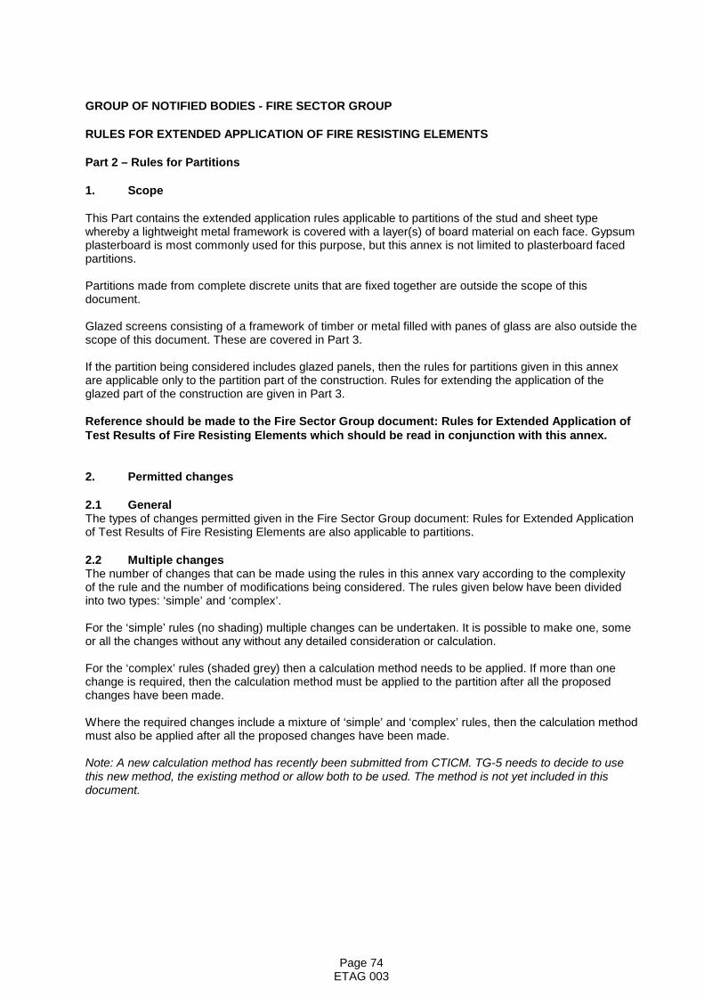
Page 74ETAG 003
GROUP OF NOTIFIED BODIES - FIRE SECTOR GROUP
RULES FOR EXTENDED APPLICATION OF FIRE RESISTING ELEMENTS
Part 2 – Rules for Partitions
1. Scope
This Part contains the extended application rules applicable to partitions of the stud and sheet typewhereby a lightweight metal framework is covered with a layer(s) of board material on each face. Gypsumplasterboard is most commonly used for this purpose, but this annex is not limited to plasterboard facedpartitions.
Partitions made from complete discrete units that are fixed together are outside the scope of thisdocument.
Glazed screens consisting of a framework of timber or metal filled with panes of glass are also outside thescope of this document. These are covered in Part 3.
If the partition being considered includes glazed panels, then the rules for partitions given in this annexare applicable only to the partition part of the construction. Rules for extending the application of theglazed part of the construction are given in Part 3.
Reference should be made to the Fire Sector Group document: Rules for Extended Application ofTest Results of Fire Resisting Elements which should be read in conjunction with this annex.
2. Permitted changes
2.1 GeneralThe types of changes permitted given in the Fire Sector Group document: Rules for Extended Applicationof Test Results of Fire Resisting Elements are also applicable to partitions.
2.2 Multiple changesThe number of changes that can be made using the rules in this annex vary according to the complexityof the rule and the number of modifications being considered. The rules given below have been dividedinto two types: ‘simple’ and ‘complex’.
For the ‘simple’ rules (no shading) multiple changes can be undertaken. It is possible to make one, someor all the changes without any without any detailed consideration or calculation.
For the ‘complex’ rules (shaded grey) then a calculation method needs to be applied. If more than onechange is required, then the calculation method must be applied to the partition after all the proposedchanges have been made.
Where the required changes include a mixture of ‘simple’ and ‘complex’ rules, then the calculation methodmust also be applied after all the proposed changes have been made.
Note: A new calculation method has recently been submitted from CTICM. TG-5 needs to decide to usethis new method, the existing method or allow both to be used. The method is not yet included in thisdocument.
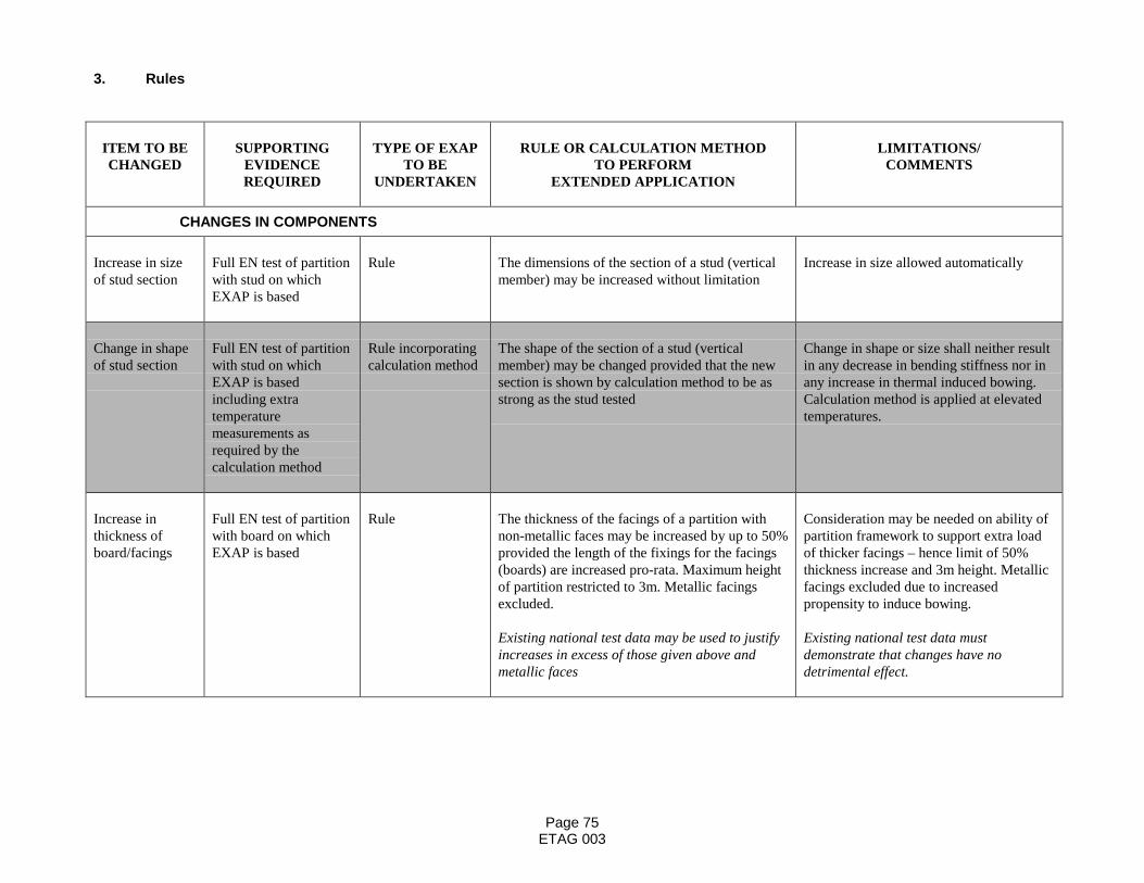
Page 75ETAG 003
3. Rules
ITEM TO BECHANGED
SUPPORTINGEVIDENCEREQUIRED
TYPE OF EXAPTO BE
UNDERTAKEN
RULE OR CALCULATION METHODTO PERFORM
EXTENDED APPLICATION
LIMITATIONS/COMMENTS
CHANGES IN COMPONENTS
Increase in sizeof stud section
Full EN test of partitionwith stud on whichEXAP is based
Rule The dimensions of the section of a stud (verticalmember) may be increased without limitation
Increase in size allowed automatically
Change in shapeof stud section
Full EN test of partitionwith stud on whichEXAP is basedincluding extratemperaturemeasurements asrequired by thecalculation method
Rule incorporatingcalculation method
The shape of the section of a stud (verticalmember) may be changed provided that the newsection is shown by calculation method to be asstrong as the stud tested
Change in shape or size shall neither resultin any decrease in bending stiffness nor inany increase in thermal induced bowing.Calculation method is applied at elevatedtemperatures.
Increase inthickness ofboard/facings
Full EN test of partitionwith board on whichEXAP is based
Rule The thickness of the facings of a partition withnon-metallic faces may be increased by up to 50%provided the length of the fixings for the facings(boards) are increased pro-rata. Maximum heightof partition restricted to 3m. Metallic facingsexcluded.
Existing national test data may be used to justifyincreases in excess of those given above andmetallic faces
Consideration may be needed on ability ofpartition framework to support extra loadof thicker facings – hence limit of 50%thickness increase and 3m height. Metallicfacings excluded due to increasedpropensity to induce bowing.
Existing national test data mustdemonstrate that changes have nodetrimental effect.
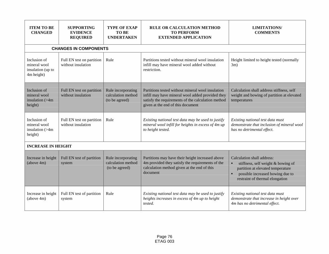
Page 76ETAG 003
ITEM TO BECHANGED
SUPPORTINGEVIDENCEREQUIRED
TYPE OF EXAPTO BE
UNDERTAKEN
RULE OR CALCULATION METHODTO PERFORM
EXTENDED APPLICATION
LIMITATIONS/COMMENTS
CHANGES IN COMPONENTS
Inclusion ofmineral woolinsulation (up to4m height)
Full EN test on partitionwithout insulation
Rule Partitions tested without mineral wool insulationinfill may have mineral wool added withoutrestriction.
Height limited to height tested (normally3m)
Inclusion ofmineral woolinsulation (>4mheight)
Full EN test on partitionwithout insulation
Rule incorporatingcalculation method(to be agreed)
Partitions tested without mineral wool insulationinfill may have mineral wool added provided theysatisfy the requirements of the calculation methodgiven at the end of this document
Calculation shall address stiffness, selfweight and bowing of partition at elevatedtemperatures
Inclusion ofmineral woolinsulation (>4mheight)
Full EN test on partitionwithout insulation
Rule Existing national test data may be used to justifymineral wool infill for heights in excess of 4m upto height tested.
Existing national test data mustdemonstrate that inclusion of mineral woolhas no detrimental effect.
INCREASE IN HEIGHT
Increase in height(above 4m)
Full EN test of partitionsystem
Rule incorporatingcalculation method (to be agreed)
Partitions may have their height increased above4m provided they satisfy the requirements of thecalculation method given at the end of thisdocument
Calculation shall address:• stiffness, self weight & bowing of
partition at elevated temperature• possible increased bowing due to
restraint of thermal elongation
Increase in height(above 4m)
Full EN test of partitionsystem
Rule Existing national test data may be used to justifyheights increases in excess of 4m up to heighttested.
Existing national test data mustdemonstrate that increase in height over4m has no detrimental effect.

Page 77ETAG 003
Calculation method for evaluating partitions with increasesin height above 4,000 mm and components
The methodology given below allows the maximum height of a stud and sheet partition system to beestablished based on data taken from a test fully in accordance with EN 1364-1:1999. The test datarequired must be taken from a test, which falls within the direct field of application of the proposedconstruction. Before commencing the exercise the assessing authority should ensure that the partitionmeets the direct field of application lateral deflection requirements during a 3000mm high test. Data takenfrom a test conducted below 3000mm is not allowed.
Step 1
Calculate weight ω of wall per square metre i.e. kg/m2 x 9,81, and select a test height L mm.
It is essential to start with a low height such as 4000mm and work upwards in 1000mm increments. Oncethe partition becomes unstable reduce the increments to 100mm until the critical height is found for theduration in question.
Step 2
Obtain stud thickness t mm, stud spacing m mm, stud depth d mm, flange width fw mm (Note 2). The yieldstress σ should be taken as the value appropriate to the quality of steel being used e.g. 210, 280 or 350N/mm2
The Young’s modulus E is assumed to be 205000 N/mm2.
Step 2
Obtain hot flange temperature Th in deg C and cold flange temperature Tc at the time at which the stabilityis to be checked. (Note 3)
Step 3
Calculate the following terms:
kh = 1 - Th /800kc = 1 -Tc /800k = kc - kh
Step 4
Calculate the neutral axis yn from the cold end:
yn = fw .( kh . d + kc . t/2) + d2 .(k/6 + kh/2)
( (kh + kc ) . (fw+ d/2))
Step 5
Calculate e = d - yn
and calculate the second moment of area of the stud Ih at elevated temperature:
Ih = t.( fw . (kh . e2 + kc . yn2 ) + e3 .(kh /3 + k . e/(12.d)) + yn3 .(kc /3 - k . yn/(12.d)))
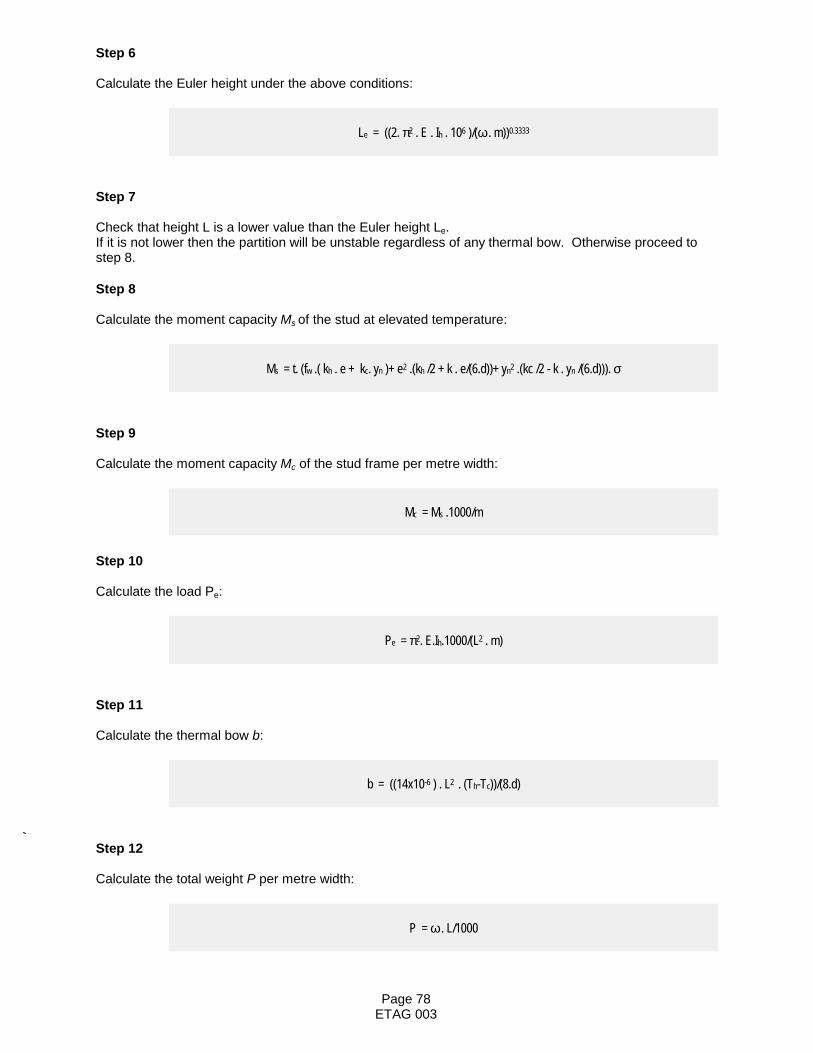
Page 78ETAG 003
Step 6
Calculate the Euler height under the above conditions:
Le = ((2. π2 . E . Ih . 106 )/(ω . m))0.3333
Step 7
Check that height L is a lower value than the Euler height Le.If it is not lower then the partition will be unstable regardless of any thermal bow. Otherwise proceed tostep 8.
Step 8
Calculate the moment capacity Ms of the stud at elevated temperature:
Ms = t. (fw .( kh . e + kc. yn )+ e2 .(kh /2 + k . e/(6.d))+ yn2 .(kc /2 - k . yn /(6.d))). σ
Step 9
Calculate the moment capacity Mc of the stud frame per metre width:
Mc = Ms .1000/m
Step 10
Calculate the load Pe:
Pe = π2. E.Ih.1000/(L2 . m)
Step 11
Calculate the thermal bow b:
b = ((14x10-6 ) . L2 . (Th-Tc))/(8.d)
Step 12
Calculate the total weight P per metre width:
P = ω . L/1000

Page 79ETAG 003
Step 13
Calculate the additional bow be due to self weight from
b e = b /(2.Pe/P -1)
Step 14
calculate the term:
α = 2 . tan-1 (2 . (b + be )/ L ) ( in radians)
Step 15
Calculate the moment M produced by the self weight acting eccentrically:
M = (ω. L2 . α . (1 - cos α ) ) / (4 .1000. sin2 α)
Step 16
Now compare the moment M with the moment capacity Mc.
If M is greater than Mc then the wall will be unstable and collapse.
If the wall is stable return to step 1 and increment the test height repeat this process until the maximumfire rated height is established to the nearest 100mm.
Note 1: Wall comprising metal C or I-studs lined each side with plasterboard. Plasterboard assumed toprovide no extra stiffness to wall but its full weight to act downwards at all times. Wall assumed to be freeat each side edge and with unrestrained head. Note 2: Where the flange has a turn down this is included in fw and where an I-stud has a doublethickness due to folding, this is included in fw. Note 3: Temperature information can be obtained from a normal fire resistance test and should beavailable at every minute during the test. The calculation will need to be done at all time increments incase conditions exist whereby stability failure occurs. A number of studs will need thermocouples attachedthe data should be used from the most onerous stud position it is not correct to average this data. In thecalculation, hot flange temperature Th must be assigned a value of no greater than 800 deg C since metalstrength is effectively zero above this value. If information is available on metal temperatures then thismodel assumes a linear temperature distribution across the web and the data must be persuaded to fitthe model.
Design Aspects of Fire Rated Partitions within Buildings
There are various design aspects which must be considered such as the total movement due to the bowand the movement at the head of the partition.
Dealing with the total bow first, this can be calculated by adding the result from Steps 11 and 13 i.e. thethermal bow and the self-weight induced bow.
The extent of the head movement depends on the net result of the vertical upward expansion due totemperature and the drop caused by the thermal bow.
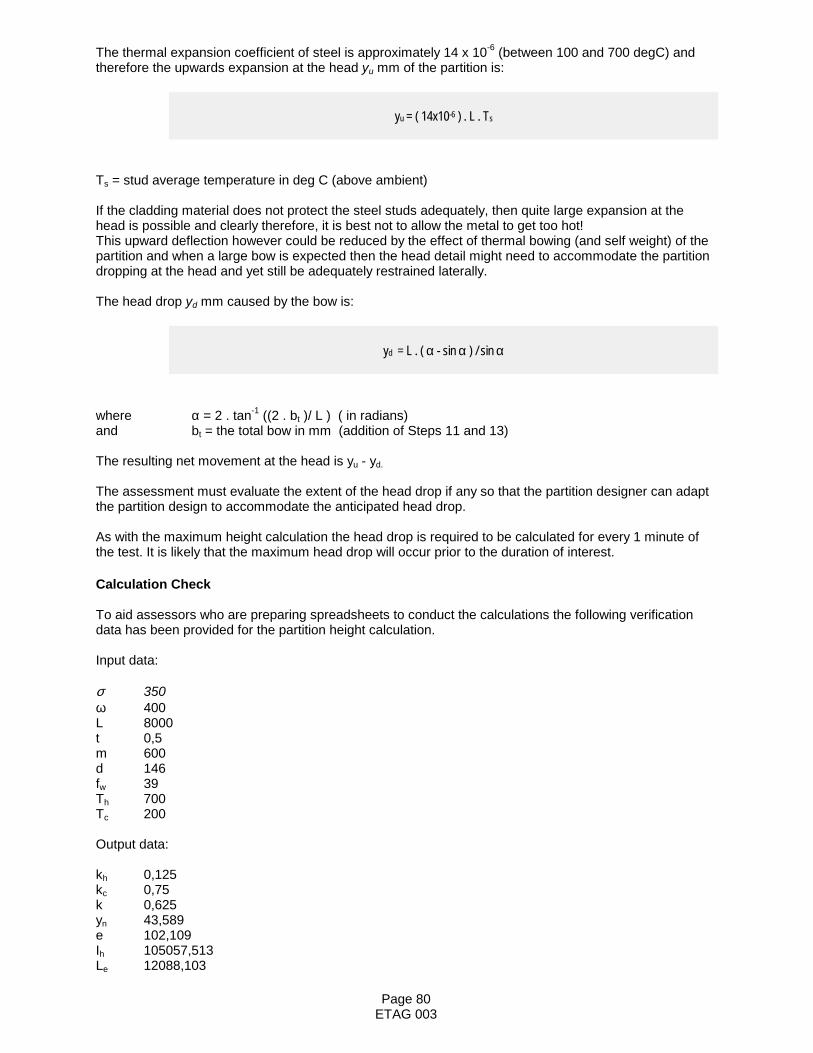
Page 80ETAG 003
The thermal expansion coefficient of steel is approximately 14 x 10-6 (between 100 and 700 degC) andtherefore the upwards expansion at the head yu mm of the partition is:
yu = ( 14x10-6 ) . L . Ts
Ts = stud average temperature in deg C (above ambient)
If the cladding material does not protect the steel studs adequately, then quite large expansion at thehead is possible and clearly therefore, it is best not to allow the metal to get too hot!This upward deflection however could be reduced by the effect of thermal bowing (and self weight) of thepartition and when a large bow is expected then the head detail might need to accommodate the partitiondropping at the head and yet still be adequately restrained laterally.
The head drop yd mm caused by the bow is:
yd = L . ( α - sin α ) / sin α
where α = 2 . tan-1 ((2 . bt )/ L ) ( in radians)and bt = the total bow in mm (addition of Steps 11 and 13)
The resulting net movement at the head is yu - yd.
The assessment must evaluate the extent of the head drop if any so that the partition designer can adaptthe partition design to accommodate the anticipated head drop.
As with the maximum height calculation the head drop is required to be calculated for every 1 minute ofthe test. It is likely that the maximum head drop will occur prior to the duration of interest.
Calculation Check
To aid assessors who are preparing spreadsheets to conduct the calculations the following verificationdata has been provided for the partition height calculation.
Input data:
σ 350ω 400L 8000t 0,5m 600d 146fw 39Th 700Tc 200
Output data:
kh 0,125kc 0,75k 0,625yn 43,589e 102,109Ih 105057,513Le 12088,103

Page 81ETAG 003
Ms 673658,153Mc 1122763,588Pe 5535,404b 383,562P 3200be 155,943α 0,268M 873638,358
Wall is stable since Mc >M

Page 82ETAG 003
GROUP OF NOTIFIED BODIES - FIRE SECTOR GROUP
RULES FOR EXTENDED APPLICATION OF FIRE RESISTING ELEMENTS
Part 3 – Rules for glazed screens
1. Scope
This Part contains the extended application rules applicable to glazed screens consisting of a frameworkof timber or metal filled with panes of glass.
Where a glazed screen is part of a partition, then the rules given in this annex are applicable only to theglazed part of the construction. Rules for extending the application of the partition part of the constructionare given in Part 2.
Reference should be made to the Fire Sector Group document: Rules for Extended Application ofTest Results of Fire Resisting Elements which should be read in conjunction with this Part.
2. Permitted changes
2.1 GeneralThe types of changes permitted given in the Fire Sector Group document: Rules for Extended Applicationof Test Results of Fire Resisting Elements are also applicable to glazed screens.
2.2 Multiple changesThe number of changes that can be made using the rules in this annex vary according to the complexityof the rule and the number of modifications being considered.
For glazed screens, the rules are all simple and do not require further evaluation e.g. by calculation.Consequently, multiple changes can be undertaken in one extended application.
However, for the rules concerned with aspect ratio and pane size, the effect of applying them together istoo onerous and consequently this needs to be limited. The limitation is given in 2.3 and to cautionNotified Bodies, the relevant rules in clause 3 subject to the limitation are shaded in grey.
2.3 Limitation on aspect ratio v. pane size
For < 30 minute applications, the rules for pane size variations can be applied in addition to the rules foradverse changes in aspect ratio.
For > 30 minute applications, either the rules for pane size increases can be applied or the rules foradverse changes in aspect ratio can be applied.
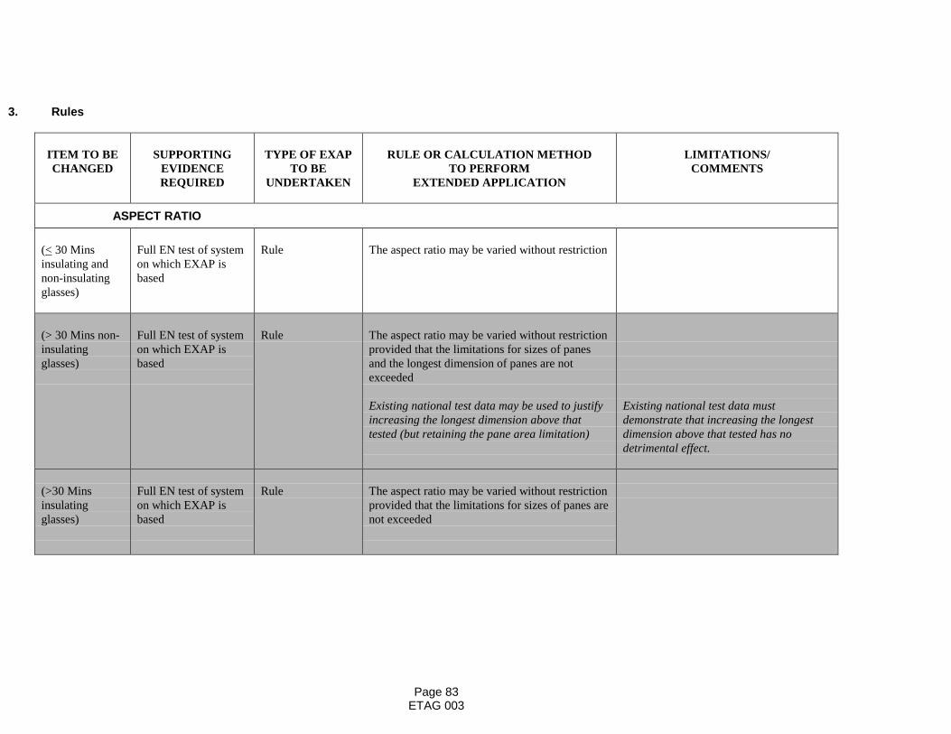
Page 83ETAG 003
3. Rules
ITEM TO BECHANGED
SUPPORTINGEVIDENCEREQUIRED
TYPE OF EXAPTO BE
UNDERTAKEN
RULE OR CALCULATION METHODTO PERFORM
EXTENDED APPLICATION
LIMITATIONS/COMMENTS
ASPECT RATIO
(< 30 Minsinsulating andnon-insulatingglasses)
Full EN test of systemon which EXAP isbased
Rule The aspect ratio may be varied without restriction
(> 30 Mins non-insulatingglasses)
Full EN test of systemon which EXAP isbased
Rule The aspect ratio may be varied without restrictionprovided that the limitations for sizes of panesand the longest dimension of panes are notexceeded
Existing national test data may be used to justifyincreasing the longest dimension above thattested (but retaining the pane area limitation)
Existing national test data mustdemonstrate that increasing the longestdimension above that tested has nodetrimental effect.
(>30 Minsinsulatingglasses)
Full EN test of systemon which EXAP isbased
Rule The aspect ratio may be varied without restrictionprovided that the limitations for sizes of panes arenot exceeded
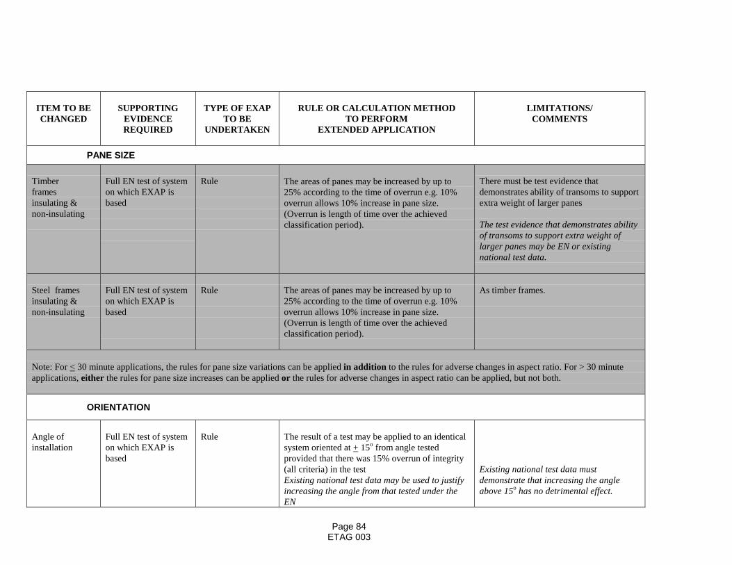
Page 84ETAG 003
ITEM TO BECHANGED
SUPPORTINGEVIDENCEREQUIRED
TYPE OF EXAPTO BE
UNDERTAKEN
RULE OR CALCULATION METHODTO PERFORM
EXTENDED APPLICATION
LIMITATIONS/COMMENTS
PANE SIZE
Timberframesinsulating &non-insulating
Full EN test of systemon which EXAP isbased
Rule The areas of panes may be increased by up to25% according to the time of overrun e.g. 10%overrun allows 10% increase in pane size.(Overrun is length of time over the achievedclassification period).
There must be test evidence thatdemonstrates ability of transoms to supportextra weight of larger panes
The test evidence that demonstrates abilityof transoms to support extra weight oflarger panes may be EN or existingnational test data.
Steel framesinsulating &non-insulating
Full EN test of systemon which EXAP isbased
Rule The areas of panes may be increased by up to25% according to the time of overrun e.g. 10%overrun allows 10% increase in pane size.(Overrun is length of time over the achievedclassification period).
As timber frames.
Note: For < 30 minute applications, the rules for pane size variations can be applied in addition to the rules for adverse changes in aspect ratio. For > 30 minuteapplications, either the rules for pane size increases can be applied or the rules for adverse changes in aspect ratio can be applied, but not both.
ORIENTATION
Angle ofinstallation
Full EN test of systemon which EXAP isbased
Rule The result of a test may be applied to an identicalsystem oriented at + 15o from angle testedprovided that there was 15% overrun of integrity(all criteria) in the testExisting national test data may be used to justifyincreasing the angle from that tested under theEN
Existing national test data mustdemonstrate that increasing the angleabove 15o has no detrimental effect.
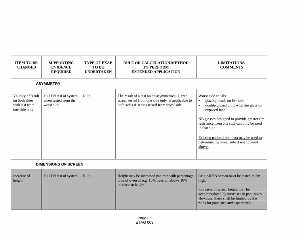
Page 85ETAG 003
ITEM TO BECHANGED
SUPPORTINGEVIDENCEREQUIRED
TYPE OF EXAPTO BE
UNDERTAKEN
RULE OR CALCULATION METHODTO PERFORM
EXTENDED APPLICATION
LIMITATIONS/COMMENTS
ASYMMETRY
Validity of resulton both sideswith test fromone side only
Full EN test of systemwhen tested from theworst side
Rule The result of a test on an asymmetrical glazedscreen tested from one side only is applicable toboth sides if it was tested from worst side
Worst side equals:• glazing beads on fire side• double glazed units with fire glass on
exposed face
NB glasses designed to provide greater fireresistance from one side can only be usedin that side
Existing national test data may be used todetermine the worst side if not coveredabove.
DIMENSIONS OF SCREEN
Increase ofheight
Full EN test of system Rule Height may be increased pro-rata with percentagetime of overrun e.g. 10% overrun allows 10%increase in height
Original EN screen must be tested at 3mhigh.
Increases in screen height may beaccommodated by increases in pane sizes.However, these shall be limited by therules for pane size and aspect ratio.

Page 86ETAG 003
Extension ofwidth
Full EN test of system Rule Unlimited extension of width is permitted Only permissible provided one verticaledge tested unfixed and unrestrained
ITEM TO BECHANGED
SUPPORTINGEVIDENCEREQUIRED
TYPE OF EXAPTO BE
UNDERTAKEN
RULE OR CALCULATION METHODTO PERFORM
EXTENDED APPLICATION
LIMITATIONS/COMMENTS
NUMBER OF PANES
Increase innumber of panes
Full EN test of system Rule The number of panes may be increased. The test specimen shall incorporate sharedmullions/transoms as appropriate.
Decrease innumber of panes
Full EN test of system Rule The number of panes may be decreased. The pane area shall not exceed maximumallowable under these rules. The aspectratio shall not be more onerous than thatallowed under these rules.
EDGE COVER
Change in edgecover
Full EN test of system Rule Edge cover may be increased for all glassesexcept edge sensitive types.Edge cover can never be decreased
TG-5 to decide on what constituted edgesensitive e.g. modified toughened soda-lime glasses.
Existing national test data may be used todetermine which glasses are edge sensitive.

Page 87ETAG 003
ITEM TO BECHANGED
SUPPORTINGEVIDENCEREQUIRED
TYPE OF EXAPTO BE
UNDERTAKEN
RULE OR CALCULATION METHODTO PERFORM
EXTENDED APPLICATION
LIMITATIONS/COMMENTS
REBATE DETAILS
Variations inglazing bead
Full EN test of system Rule Centres of fixings may be decreased, but notincreased
Pinned V. screwfixed timberglazing beads
Full EN test of systemwith pinned on glazingbeads
Rule A test on glazing beads that are pinned (nailed) inposition covers an end-use where the glazing beadare screwed in position.
• converse does not apply• angle of fixings cannot change by
more than 10o
• extent of fixing ‘crossover’ cannot bereduced
Existing national test data may be used tojustify >10o change in angle.
Stud located V.screw fixed steelglazing beads
Full EN test of systemwith stud locatedglazing beads
Rule A test on steel glazing beads that are stud located(clip-on type) covers an end-use where theglazing beads are screwed in position.
Permitted provided there is no:• weakening of retention• decrease of any shielding effect• increased exposure to radiant heat
FRAMING/SUPPORTING CONSTRUCTION
Changes tosupportingconstruction/fixing of frames
Full EN test of system Rule The result is applicable to any supportingconstruction of at least the same fire resistance asthat testedThe fixings used to fix the glazed screen may bevaried
The maximum fixing centres shall not beexceeded and the minimum number offixings cannot be reduced
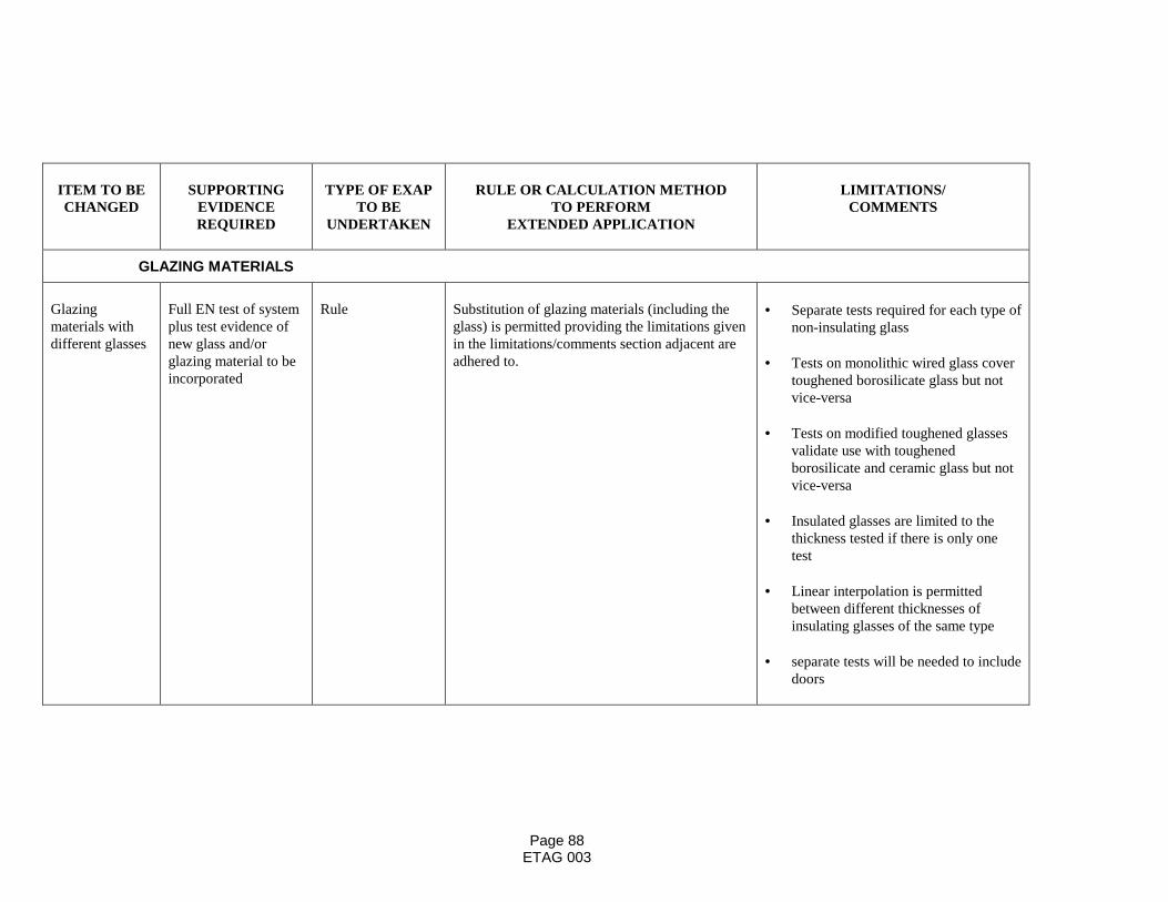
Page 88ETAG 003
ITEM TO BECHANGED
SUPPORTINGEVIDENCEREQUIRED
TYPE OF EXAPTO BE
UNDERTAKEN
RULE OR CALCULATION METHODTO PERFORM
EXTENDED APPLICATION
LIMITATIONS/COMMENTS
GLAZING MATERIALS
Glazingmaterials withdifferent glasses
Full EN test of systemplus test evidence ofnew glass and/orglazing material to beincorporated
Rule Substitution of glazing materials (including theglass) is permitted providing the limitations givenin the limitations/comments section adjacent areadhered to.
• Separate tests required for each type ofnon-insulating glass
• Tests on monolithic wired glass covertoughened borosilicate glass but notvice-versa
• Tests on modified toughened glassesvalidate use with toughenedborosilicate and ceramic glass but notvice-versa
• Insulated glasses are limited to thethickness tested if there is only onetest
• Linear interpolation is permittedbetween different thicknesses ofinsulating glasses of the same type
• separate tests will be needed to includedoors