european guidelines on quality criteria for … · the guidelines will be available in nine...
TRANSCRIPT

EUROPEAN COMMISSION
EUROPEAN GUIDELINESON QUALITY CRITERIAFOR DIAGNOSTIC RADIOGRAPHIC IMAGES
EUR 16260 EN Let alone a MAGRITTE

Cover picture M.C.O. Trouveroy: ‘La radiologie dans l’histoire d’après Magritte’© 1995 — B — LC O - Trouveroy

EUROPEAN GUIDELINESON QUALITY CRITERIA FORDIAGNOSTIC RADIOGRAPHIC IMAGES
une 1996
UR 16260 EN

EUROPEAN COMMISSIONDirectorate-General XII: Science, Research and Development
A great deal of additional information on the European Union is available on the Internet. t can be accessed through the Europa server (http://europa.eu.int).
Cataloguing data can be found at the end of this publication
uxembourg: Office for Official Publications of the European Communities, 1996
SBN 92-827-7284-5
© ECSC-EC-EAEC, Brussels • Luxembourg, 1996
Reproduction is authorized, except for commercial purposes, provided the source is acknowledged
Printed in Luxembourg

EUROPEAN GUIDELINES ON QUALITY CRITERIA FOR DIAGNOSTIC RADIOGRAPHIC IMAGES
These Guidelines result from a European-wide cooperationbetween the various professionals and authorities involved inDiagnostic Radiology (see Chapter 4).
The present Report has been edited by the restricted StudyGroup on Quality Criteria Development of the EuropeanCommission:
J. H. E. Carmichael (UK)C. Maccia (F)B. M. Moores (UK)J. W. Oestmann (D)H. Schibilla (CEC)D. Teunen (CEC)R. Van Tiggelen (B)B. Wall (UK)
June 1996 -
UR 16260 EN
CONTENTS
PAGE
Preamble VII
CHAPTER 1 Quality Criteria for Diagnostic Radiographic Images 1
CHAPTER 2 Summary of the Evaluation of two European Trials of the Quality Criteria for Diagnostic Radiographic Images 29
CHAPTER 3 Quality Criteria Implementation and Audit Guidelines 47
CHAPTER 4 List of All Those Who Contributed to the Establishment, Testing and Evaluation of the Quality Criteria Presented in these Guidelines 75

PREAMBLE
Quality and safety have become hallmarks for efficient and successful medical interven-ion. A comprehensive quality and safety culture has been progressively developedhroughout the European Union with regard to the medical use of ionizing radiation, and
has been integrated into the various branches of diagnosis and treatment.
he Commission of the European Communities has contributed to this evolution by thestablishment of legal requirements for the radiation protection of persons undergoing
medical examination or treatment,1 as well as safety requirements for medical devices,2
nd by participating in research for the implementation and updating of these require-ments.
he establishment of the Quality Criteria for Diagnostic Radiographic Images is one of themilestones of these European initiatives. It started in 1984, when the first Directive onRadiation Protection of the Patient1 was adopted by the Member States of the EuropeanUnion.
hese Quality Criteria have been elaborated in a common effort by radiologists, radiogra-phers, physicists, radiation protection experts, health authorities and professional, nationalnd international organizations. They were first set up for conventional radiography, oncentrating on examinations of high frequency or with relatively high doses to the patient.t is the aim of the Quality Criteria to characterize a level of acceptability for normal basicadiographs which could answer to any clinical indication. Furthermore, it has been ecognized that the Quality Criteria must be specifically adapted to paediatric radiology.3
he applicability of the Quality Criteria for adult radiology has been checked in European-wide trials, involving some hundred radiological departments and about 3 000 radi-ographic images and dose measurements. The results have been discussed at workshops,by working parties and by dedicated study groups; advice and comments have been col-ected from professional associations, individual experts and healthcare authorities. Theonclusions have been integrated into the present Document and provided ele-
ments for the improvement of the lists of Quality Criteria.
he European Guidelines on Quality Criteria for Diagnostic Radiographic Images containsour chapters: the first one concerns the updated lists of the Quality Criteria for six con-entional examinations: Chest, Skull, Pelvis, Lumbar Spine, Urinary Tract and Breast.
t defines Diagnostic Requirements for a normal, basic radiograph, specifying anatomicalmage criteria and important image details; it indicates Criteria for the Radiation Dose to
EUROPEAN GUIDELINESON QUALITY CRITERIA FOR DIAGNOSTIC RADIOGRAPHIC IMAGES
Council Directive 84/466/Euratom, OJ L 265/1, 5.10.1984.Council Directive 93/42/EEC, OJ L 169/1 12.7.1993.Report EUR 16261, 1996.

the Patient and gives an Example for Good Radiographic Technique by which theDiagnostic Requirements and the dose criteria can be achieved.
The second chapter summarizes the analysis of the findings of the European-wide Trials4
and explains the updating of the Quality Criteria, as listed in Chapter 1.
The third chapter outlines a procedure for implementing and auditing the Quality Criteria.A sample questionnaire and scoring tables for the six examinations, which were elabor-ated during the evaluation of the Trials, have been reproduced and could become toolsfor self-education and performance checking.
The fourth chapter presents all those to whom the European Commission’s services wishto express their sincere thanks for their cooperation and creative criticism, from which theEuropean Commission’s Radiation Protection Actions drew their encouragement to con-centrate on the development of this Quality Criteria concept.
These efforts will continue in the near future in the framework of the coming researchprogrammes and in the up-dating of the EURATOM Directive.1 The ongoing revision ofthis Directive proposes the establishment of quality assurance measures including criteriathat can be employed and checked in a comparable way so that the radiation dose to thepatient can be linked to the required image quality and to the performance of the radi-ographic procedure. The indication of reference dose values is also recommended.
Therefore, it is with great satisfaction that the services of the European Commission pre-sent these ‘European Guidelines on Quality Criteria for Diagnostic Radiographic Images’.The Guidelines do not claim to give strict instructions on day-to-day radiological practice,but attempt to introduce basic criteria that have been proved to lead to the necessaryquality of the diagnostic information with reasonable dose values applied to the patient.This is a first step in the optimization of medical exposures, whereby a lower quality stan-dard should ideally be associated to lower dose. Compliance with these Guidelines willhelp to protect the patient and staff against unnecessary radiation exposure, and will pre-vent any degradation of the equipment or faulty use of the imaging procedure fromresulting in unsatisfactory images.
It is the hope of the European Commission’s services that the Guidelines will stimulate theprofessionals involved in diagnostic radiology to look for improvements in the criteria andtheir extension to other types of examination or new techniques.
The Guidelines will be available in nine official languages of the European Union.
Dr H. Eriskat Dr J. SinnaeveDirectorate-General Directorate-GeneralEnvironment, Nuclear Safety and Civil Protection Science, Research and Development Radiation Protection Radiation Protection Research
4 For detailed results and findings see Report EUR 16635, in press.

CHAPTER 1
QUALITY CRITERIA FOR DIAGNOSTIC RADIOGRAPHIC IMAGES
TABLE OF CONTENTS
Introduction 2Objectives 3General Principles Associated with Good Imaging Performance 4Guidance on Implementation 7Description of Terms 8List of References of Chapter 1 9
List of Quality Criteria for Diagnostic Radiographic Images 11
CHEST (LUNGS AND HEART) PA and Lateral projections 12
SKULL PA and Lateral projections 14
LUMBAR SPINE AP/PA and Lateral projections and lateral projection of lumbo-sacral joint 16
PELVIS AP projection 19
URINARY TRACT AP projection before and after administration of contrast medium 20
BREAST MLO and CC projections 22
APPENDIX I Guidelines on Radiation Dose to the Patient 27

INTRODUCTION
The two basic principles of radiation protection of the patient as recommended by ICRPare justification of practice and optimization of protection, including the consideration ofdose reference levels (1,2,3,). These principles are largely translated into a legal frame-work by the EURATOM Directive (4).
Justification is the first step in radiation protection. It is accepted that no diagnostic expo-sure is justifiable without a valid clinical indication, no matter how good the imaging per-formance may be. Every examination must result in a net benefit for the patient. This onlyapplies when it can be anticipated that the examination will influence the efficacy of thedecision of the physician with respect to the following:
— diagnosis,
— patient management and therapy,
— final outcome for the patient.
Justification also implies that the necessary result cannot be achieved with other methodswhich would be associated with lower risks for the patient.
As a corollary, justification requires that the selected imaging procedure is acceptably reli-able, i.e. its results are reproducible and have sufficient sensitivity, specificity, accuracy, andpredictive value with respect to the particular clinical question.
Justification also necessitates that a person, trained and experienced in radiological tech-niques and in radiation protection (as recognised by the competent authority), normally aradiologist, takes the overall clinical responsibility for an examination. This person shouldwork in close contact with the referring physician in order to establish the most appro-priate procedure for the patient management and therapy. The responsible person can —as appropriate — delegate responsibility to perform the examination to a qualified tech-nician, who must be suitably trained and experienced.
Guidance on referral criteria for adult and paediatric patients can be found in WHOreports 689 (5), and 757 (6), respectively, and guidelines for making the best use of adepartment of radiology are available from the Royal College of Radiologists London, (7a)and from the German Federal Medical Board (7b).
In respect of diagnostic examinations ICRP does not recommend the application of doselimits to patient irradiation but draws attention to the use of dose reference levels as anaid to optimisation of protection in medical exposure. Once a diagnostic examination hasbeen clinically justified, the subsequent imaging process must be optimized. The optimaluse of ionizing radiation involves the interplay of three important aspects of the imagingprocess:
— the diagnostic quality of the radiographic image,
— the radiation dose to the patient,
— the choice of radiographic technique.
This document provides guidelines on all three of these aspects. As it is not practicable toassess the full range of radiodiagnostic procedures, examinations have been chosen whichare either common or give significant patient dose, or both. The examinations are: chest,skull, lumbar spine, pelvis, urinary tract and breast. No attempt has been made to definethe procedure for complete examinations. These are often a matter of personal preferenceof a radiologist and will be determined by local conditions and particular clinical situa-tions. Instead, Quality Criteria have been drawn up for representative radiographs fromthe six routine examinations listed above. Compliance with the criteria for these radi-ographs is a first but important step in ensuring satisfactory overall performance.
Similar documents have been prepared for conventional radiodiagnostic procedures inpaediatric radiology (8) and for computed tomography (9). The need for a comparableeffort for fluoroscopy employing image intensification is recognized.
OBJECTIVES
he objectives of the guidelines presented in this document are to achieve:
— adequate image quality, comparable throughout Europe; and
— reasonably low radiation dose per radiograph.
hey will also provide the basis for accurate radiological interpretation of the image.
he European Guidelines are primarily directed at the technical and clinical staff involvedn taking the radiographs and in reporting on them. They will also be of interest to thoseesponsible for the design of X-ray imaging equipment and for the maintenance of itsunctional performance. They will be helpful to those who have responsibility for equip-
ment specification and purchase.
he Guidelines represent an achievable standard of good practice which can be used as abasis for further development by the radiological community.
he DIAGNOSTIC REQUIREMENTS presented as image criteria for a particular type of radi-ograph are those deemed necessary to produce an image of standard quality. No attempthas been made to define acceptability for particular clinical indications.
he CRITERIA FOR RADIATION DOSE TO THE PATIENT are expressed in terms of a refer-nce dose value for each type of radiograph which is based on the third quartile (75. per-entile) value seen in earlier European patient dose surveys. Its purpose, if it is exceeded,s to initiate an immediate investigation into the reasons for using relatively high doseechniques and to trigger appropriate corrective action. The reference dose value can beaken as a ceiling from which progress should be pursued to lower dose levels in line withhe ALARA (as low as reasonably achievable) principle.
he EXAMPLES OF GOOD RADIOGRAPHIC TECHNIQUE included in this document havevolved from the results of two European trials of the Quality Criteria. Compliance withhe image and patient dose criteria was possible when the recommended techniques
were used.
o encourage widespread use, the image criteria have been expressed in a manner requir-ng personal visual assessment rather than objective physical measurements which needophisticated equipment unavailable to most departments. However, the assessment ofompliance with the criteria for radiation dose to the patient for a specific radiograph
unavoidably involves some form of dose measurement. This requires representative sam-pling of the patient population. A number of dose measurements methods are describedn Appendix I.

GENERAL PRINCIPLES ASSOCIATED WITH GOOD IMAGING PERFORMANCE
The following general principles are common to all radiographic X-ray examinations. Allthose who either carry out or report on the results should be aware of them. Specificaspects of these principles are discussed in greater detail in a number of publications bynational and international organizations, some of which are listed in references (11) to(15) (see page 9).
1. Image Annotation
The patient identification, the date of examination, positional markers and the name ofthe facility must be present and legible on the film. These annotations should not obscurethe diagnostically relevant regions of the radiograph. An identification of the radiogra-phers on the film would also be desirable.
2. Quality Control of X-ray Imaging Equipment
Quality control programmes form an essential part of dose-effective radiological practice.Such programmes should be instigated in every medical X-ray facility and should cover aselection of the most important physical and technical parameters associated with thetypes of X-ray examination being carried out. Limiting values for these technical parame-ters and tolerances on the accuracy of their measurement will be required for meaningfulapplication of the Examples of Good Radiographic Technique presented in theseGuidelines. BIR Report 18 (12) provides useful information on this subject.
3. Patient Positioning
Correct patient positioning plays a major role in determining the success of any radiolog-ical examination. Routine positioning may need to be altered in the light of specific clini-cal circumstances, in order to delineate an area of special interest. Correct positioning ofthe patient is the responsibility of the person who is physically directing the examination.The use of suitable immobilization and compression techniques can have an importantrole to play in the production of satisfactory images. Training programmes as well asongoing multidisciplinary evaluation and audit programmes within a medical X-ray facili-ty should regularly address these areas.
4. X-ray Beam Limitation
Image quality is improved and the radiation dose to the patient is reduced by limiting theX-ray beam to the smallest field giving the required diagnostic information. Limitation ofthe radiation beam should also consider the need to exclude radiosensitive organs fromprimary irradiation whenever possible. On no occasion should the X-ray beam fall outsidethe image receptor area. It is desirable for there to be evidence on the radiograph of beamlimitation. An automated beam limitation device would be of help.
5. Protective Shielding
For radiation protection purposes, standard protection devices should be available toshield radiosensitive tissues or organs whenever possible. In particular, for patients ofreproductive capacity, testes or ovary shields should be used in examinations when theseorgans are likely to be in or near the primary beam.

6. Radiographic Exposure Conditions
Knowledge and correct use of appropriate radiographic exposure factors, for example.adiographic voltage, nominal focal spot value, tube filtration, and film-focus-distance is
necessary because they have a considerable impact on patient dose and image quality.ermanent parameters of the apparatus such as total tube filtration and grid characteris-ics should also be taken into consideration.
7. Screen Film System
he sensitivity of screen film systems is defined in terms of speed (see ISO 9236-1, DIN6867, Section 1 (1995)). The speed of the screen film system is one of the most criticalactors affecting the radiation dose to the patient. The variation in sensitivity which can
occur with changes in X-ray beam energy for individual screen film systems (BIR Report 1812)) is recognized. Therefore, for convenience in this document only broad speed cate-gories (nominal speed classes) are used. Users should be encouraged to measure the realpeeds of their screen film systems under standard conditions resembling those used in
practice, to see how closely they match up to the manufacturers quoted values. Speedlasses of 200 and above usually require the use of rare earth or equivalent intensifyingcreens. Users are also encouraged to measure the resolution of their screen film systemince this varies within any speed class.
8. Film Blackening
ilm blackening (optical density) has a major influence on image quality. For the sameadiographic projection it depends on many factors: radiation dose, radiation quality,
patient size, radiographic technique, image receptor sensitivity and film processing. Itdetermines the optical densities of a radiographic film. The range of the mean opticaldensity (D) of a clinical radiograph should normally lie between D = 1.0 and D = 1.4 (forhe breast examination 1.3 - 1.8 are recommended) and the optical densities of fog andilm base should not exceed D = 0.25. For the diagnostically relevant parts of the film, the
overall range of optical densities should lie between 0.5 and 2.2.
Whereas the total density above fog and base can be easily — and should be routinely —measured, objective measurement of the mean optical density of the film of a patientequires some expenditure and is not practicable in daily work. Even in external qualityontrol programmes assessors usually base their judgment on subjective and globalmpression rather than measurements. For a more precise assessment, the definition ofone or a few critical points of the particular radiographic projections would be desirablewhere the optical density of a specific anatomical feature — and its contrast relative tohe surrounding image — could be measured.
ilm blackening is subject to personal preference of the individual radiologist. A darkerilm may be associated with a relatively higher patient dose. In this respect, the preferenceor darker films should be supported by rational arguments. A film which has been foundo be too dark should be viewed with a bright spotlight before a decision is made toepeat the examination.
9. Radiographic Exposures per Examination
he number of radiographic exposures within one examination must be kept to a mini-mum consistent with obtaining the necessary diagnostic information.
10. Film Processing
Optimal processing of the radiographic film has important implications both for the diag-nostic quality of the image and for the radiation dose to the patient. Film processors

should be maintained at their optimum operating conditions as determined by regularand frequent (i.e. daily) quality control procedures. Consistent imaging performance is notnecessarily an indication of optimal performance, for example the developer temperaturemay well be set too low.
11. Image Viewing Conditions
The proper assessment of image quality and accurate reporting on the diagnostic infor-mation in the radiographs can best be achieved when the viewing conditions meet thefollowing requirement:
(a) The light intensity incident on the viewer’s eye should be about 100 cd/m2. To achievethis, the brightness of the film illuminator should be between 2 000 and 4 000 cd/m2
for films in the density range 0.5 to 2.2.
(b) The colour of the illumination should be white or blue and should be matchedthroughout a complete set of film illuminators.
(c) Means should be available to restrict the illuminated area to the area of the radiographto avoid dazzling.
(d) Means for magnifying details in the displayed radiographic image should be available.These means should magnify by a factor of 2 to 4 and contain provisions to identifysmall image details of sizes down to 0.1 mm.
(e) For viewing exceptionally dark areas in the radiographic image an additional spotlightwith iris diaphragm providing a brightness of at least 10 000 cd/m2 should be avail-able.
(f) A low level of ambient light in the viewing room is essential.
12. Reject Analysis
Rejected films should be collected, the reasons for rejection should be analysed and cor-rective action should be taken.

GUIDANCE ON IMPLEMENTATION
Quality Criteria are presented for a number of selected radiographic projections used inhe course of routine types of X-ray examination. They apply to adult patients of standardize (70 kg, or 5 cm compressed breast) with the usual presenting symptoms for the type
of examination being considered. These Quality Criteria are to be used by radiologists,adiographers and medical physicists as a check on the routine performance of the entiremaging process.
However, the Quality Criteria cannot be applied to all cases. For certain clinical indications lower level of image quality may be acceptable, but this should ideally always be asso-iated with a lower radiation dose to the patient.
Under no circumstances should an image which fulfils all clinical requirementsbut does not meet all image criteria ever be rejected.
or each selected radiographic projection the Quality Criteria are divided into three parts:
1. DIAGNOSTIC REQUIREMENTS
Image criteria
These list image criteria which in most cases specify important anatomical structures that should be visible on a radi-ograph to aid accurate diagnosis. Some of these criteria depend fundamentally on correct positioning and coopera-tion of the patient, whereas others reflect technical performance of the imaging system. Awareness of the position-al and technical dependence of the criteria can stimulate further work aimed at gaining a more detailed under-standing of those factors which can influence image quality (see for example ‘Evaluation of the European ImageQuality Criteria for Chest Examinations‘, E. Vañó et al. BJR 68, 1349-1355, 1995). This should lead to improved mech-anisms for auditing both existing as well as new and/or modified radiographic techniques and training programmesfor radiological staff.
A qualitative guide to the necessary degree of visibility of these essential structures is provided in the followingDescription of Terms. These criteria can be used by radiologists as they report on radiographs to make a personal visu-al assessment of the image quality as well as an audit mechanism for radiographic procedures within a department.
Important image details
These provide quantitative information on the minimum sizes at which important anatomical details should becomevisible on the radiograph. Some of these anatomical details may be pathological and therefore may not be present.
2. CRITERIA FOR RADIATION DOSE TO THE PATIENT
Reference values are provided for the entrance surface dose to a standard-sized patient for each type of radiographconsidered. The derivation of these values is discussed in Appendix 1.
3. EXAMPLE OF GOOD RADIOGRAPHIC TECHNIQUE
This provides an example of one set of radiographic technique parameters that has been found to result in good imag-ing performance that is capable of meeting all the above Quality Criteria. Details are also given of a suitable combina-tion of accessory devices, geometrical conditions and loading factors using current X-ray imaging technology. If radiol-ogists and radiographers find that Diagnostic Requirements or Criteria for Radiation Dose to the Patient are not metthen the Example of Good Radiographic Technique can be used as a guide to how their techniques might be improved.
2. CRITERIA FOR RADIATION DOSE TO THE PATIENT
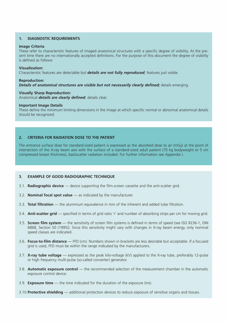
The entrance surface dose for standard-sized patient is expressed as the absorbed dose to air (mGy) at the point ofintersection of the X-ray beam axis with the surface of a standard-sized adult patient (70 kg bodyweight or 5 cmcompressed breast thickness), backscatter radiation included. For further information see Appendix I.
1. DIAGNOSTIC REQUIREMENTS
Image CriteriaThese refer to characteristic features of imaged anatomical structures with a specific degree of visibility. At the pre-sent time there are no internationally accepted definitions. For the purpose of this document the degree of visibilityis defined as follows:
Visualization:Characteristic features are detectable but details are not fully reproduced; features just visible.
Reproduction:Details of anatomical structures are visible but not necessarily clearly defined; details emerging.
Visually Sharp Reproduction:Anatomical details are clearly defined; details clear.
Important Image DetailsThese define the minimum limiting dimensions in the image at which specific normal or abnormal anatomical detailsshould be recognized.
3. EXAMPLE OF GOOD RADIOGRAPHIC TECHNIQUE
3.1. Radiographic device — device supporting the film-screen cassette and the anti-scatter grid.
3.2. Nominal focal spot value — as indicated by the manufacturer.
3.3. Total filtration — the aluminium equivalence in mm of the inherent and added tube filtration.
3.4. Anti-scatter grid — specified in terms of grid ratio ‘r’ and number of absorbing strips per cm for moving grid.
3.5. Screen film system — the sensitivity of screen film systems is defined in terms of speed (see ISO 9236-1, DIN6868, Section 50 (1995)). Since this sensitivity might vary with changes in X-ray beam energy, only nominalspeed classes are indicated.
3.6. Focus-to-film distance — FFD (cm). Numbers shown in brackets are less desirable but acceptable. If a focusedgrid is used, FFD must be within the range indicated by the manufacturers.
3.7. X-ray tube voltage — expressed as the peak kilo-voltage (kV) applied to the X-ray tube, preferably 12-pulseor high frequency multi-pulse (so-called converter) generator.
3.8. Automatic exposure control — the recommended selection of the measurement chamber in the automaticexposure control device.
3.9. Exposure time — the time indicated for the duration of the exposure (ms).
3.10.Protective shielding — additional protection devices to reduce exposure of sensitive organs and tissues.

LIST OF REFERENCES FOR CHAPTER 1
The following is a limited reference list. References (11) to (15) contain extensive reference lists.
(1) ICRP Publication 60, ‘1990 Recommendations of the International Commission on Radiological Protection’, Annals ofthe ICRP Vol. 21, Nos 1-3 (Pergamon Press, Oxford), 1991.
(2) ICRP Publication 34, ‘Protection of the Patient in Diagnostic Radiology’, Annals of the ICRP Vol. 9, Nos 2-3 (PergamonPress, Oxford), 1982.
(3) ICRP Publication 73, ‘Radiological Protection and Safety in Medecine’, (Pergamon Press, Oxford), in press.
(4) Council Directive of 3 September 1984 laying down basic measures for the radiation protection of persons under-going medical examination or treatment (84/466/EURATOM) OJ L 265, p. 1, 5.10.1984, under revision: COM(95) 560final 1995.
(5) WHO Technical Report 689 ‘A Rational Approach to Radiographic Investigations‘, (World Health Organization,Geneva), 1986.
(6) WHO Technical Report 757 ‘Rational Use of Diagnostic Imaging in Paediatrics‘, (World Health Organization, Geneva),1987.
(7a) Making the Best Use of a Department of Radiology, Royal College of Radiologists, London, 3rd edition, 1995.
(7b) Guidelines of the German Federal Medical Board on ‘Quality Assurance in Diagnostic Radiology’, Dt. Ärztebl.92, Heft34-35, 1995, in German.
(8) Quality Criteria for Diagnostic Radiographic Images in Paediatrics, (Office for Official Publications of the EuropeanCommunities, Luxembourg), Report EUR 16261, 1996.
(9) Quality Criteria for Computed Tomography, (Office for Official Publications of the European Communities,Luxembourg), Report EUR 16262, 1996.
(10) WHO Report ‘Quality Assurance in Diagnostic Radiology‘, (World Health Organization, Geneva), 1982.
(11) ‘Criteria and Methods for Quality Assurance in Medical X-ray Diagnosis’, BJR Supplement No 18, 1985.
(12) ‘Technical and Physical Parameters for Quality Assurance in Medical Diagnostic Radiology; Tolerances, Limiting Valuesand Appropriate Measuring Methods’, BIR Report 18, 1989.
(13) ‘Optimization of Image Quality and Patient Exposure in Diagnostic Radiology’, BIR Report 20, 1989.
(14) ‘Test Phantoms and Optimization in Diagnostic Radiology and Nuclear Medicine; Radiation Protection Dosimetry’, Vol. 49, Nos 1-3, 1993.
(15) ‘Quality Control and Radiation Protection of the Patient in Diagnostic Radiology and Nuclear Medicine; RadiationProtection Dosimetry’, Vol. 57, Nos 1-4, 1995.


LIST OF QUALITY CRITERIA FOR DIAGNOSTIC RADIOGRAPHIC IMAGES

LIST
OF
QU
ALI
TY C
RIT
ERIA
FO
R D
IAG
NO
STIC
RA
DIO
GR
APH
IC IM
AG
ES
1. DIAGNOSTIC REQUIREMENTS
1.1. Image criteria
1.1.1. Performed at full inspiration (as assessed by the position of the ribs above thediaphragm — either 6 anteriorly or 10 posteriorly) and with suspended respiration
1.1.2. Symmetrical reproduction of the thorax as shown by central position of the spin-ous process between the medial ends of the clavicles
1.1.3. Medial border of the scapulae to be outside the lung fields1.1.4. Reproduction of the whole rib cage above the diaphragm1.1.5. Visually sharp reproduction of the vascular pattern in the whole lung, particularly
the peripheral vessels1.1.6. Visually sharp reproduction of:
(a) the trachea and proximal bronchi,(b) the borders of the heart and aorta, (c) the diaphragm and lateral costo-phrenic angles
1.1.7. Visualiszation of the retrocardiac lung and the mediastinum1.1.8. Visualization of the spine through the heart shadow
1.2. Important image details
1.2.1. Small round details in the whole lung, including the retrocardiac areas: high contrast: 0.7 mm diameterlow contrast: 2 mm diameter
1.2.2. Linear and reticular details out to the lung periphery:high contrast: 0.3 mm in width,low contrast: 2 mm in width
2. CRITERIA FOR RADIATION DOSE TO THE PATIENT
Entrance surface dose for a standard-sized patient: 0.3 mGy
3. EXAMPLE OF GOOD RADIOGRAPHIC TECHNIQUE
3.1. Radiographic device: vertical stand with stationary or moving grid
3.2. Nominal focal spot value: ≤ 1.3
3.3. Total filtration: ≥ 3.0 mm Al equivalent
3.4. Anti-scatter grid: r = 10; 40/cm
3.5. Screen film system: nominal speed class 400
3.6. FFD: 180 (140-200) cm
3.7. Radiographic voltage: 125 kV
3.8. Automatic exposure control: chamber selected — right lateral
3.9. Exposure time: < 20 ms
3.10. Protective shielding: standard protection
PA PROJECTION

LATERAL PROJECTIONif indicated after viewing PA film)
1. DIAGNOSTIC REQUIREMENTS
1.1. Image criteria
1.1.1. Performed at full inspiration and with suspended respiration
1.1.2. Arms should be raised clear of the thorax
1.1.3. Superimposition of the posterior lung borders
1.1.4. Reproduction of the trachea
1.1.5. Reproduction of the costo-phrenic angles
1.1.6. Visually sharp reproduction of the posterior border of the heart, the aorta, mediastinum, diaphragm, sternum and thoracic spine
1.2. Important image details
1.2.1. Small round details in the whole lung:
high contrast: 0.7 mm diameter
low contrast: 2 mm diameter
1.2.2. Linear and reticular details out to the lung periphery:
high contrast: 0.3 mm in width
low contrast: 2 mm in width
2. CRITERIA FOR RADIATION DOSE TO THE PATIENT
Entrance surface dose for a standard-sized patient: 1.5 mGy
3. EXAMPLE OF GOOD RADIOGRAPHIC TECHNIQUE
3.1. Radiographic device: vertical stand with stationary or moving grid
3.2. Nominal focal spot value: ≤ 1.3
3.3. Total filtration: ≥ 3.0 mm Al equivalent
3.4. Anti-scatter grid: r = 10; 40/cm
3.5. Screen film system: nominal speed class 400
3.6. FFD: 180 ( 140-200 ) cm
3.7. Radiographic voltage: 125 kV
3.8. Automatic exposure control: chamber selected — central
3.9. Exposure time: < 40 ms
3.10. Protective shielding: standard protection
LIST
OF
QU
ALI
TY C
RIT
ERIA
FO
R D
IAG
NO
STIC
RA
DIO
GR
APH
IC IM
AG
ES
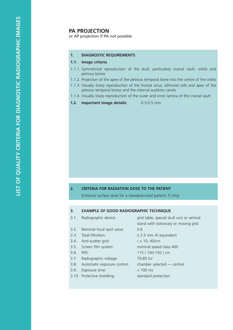
1. DIAGNOSTIC REQUIREMENTS
1.1. Image criteria
1.1.1. Symmetrical reproduction of the skull, particularly cranial vault, orbits andpetrous bones
1.1.2. Projection of the apex of the petrous temporal bone into the centre of the orbits
1.1.3. Visually sharp reproduction of the frontal sinus, ethmoid cells and apex of thepetrous temporal bones and the internal auditory canals
1.1.4. Visually sharp reproduction of the outer and inner lamina of the cranial vault
1.2. Important image details: 0.3-0.5 mm
2. CRITERIA FOR RADIATION DOSE TO THE PATIENT
Entrance surface dose for a standard-sized patient: 5 mGy
3. EXAMPLE OF GOOD RADIOGRAPHIC TECHNIQUE
3.1. Radiographic device: grid table, special skull unit or vertical
stand with stationary or moving grid
3.2. Nominal focal spot value: 0.6
3.3. Total filtration: ≥ 2.5 mm Al equivalent
3.4. Anti-scatter grid: r = 10; 40/cm
3.5. Screen film system: nominal speed class 400
3.6. FFD: 115 ( 100-150 ) cm
3.7. Radiographic voltage: 70-85 kV
3.8. Automatic exposure control: chamber selected — central
3.9. Exposure time: < 100 ms
3.10. Protective shielding: standard protection
PA PROJECTIONor AP projection if PA not possible

LATERAL PROJECTION
1. DIAGNOSTIC REQUIREMENTS
1.1. Image criteria
1.1.1. Visually sharp reproduction of the outer and inner lamina of the cranial vault, thefloor of the sella, and the apex of the petrous temporal bone
1.1.2. Superimposition respectively of the contours of the frontal cranial fossa, the lesser wing of the sphenoid bone, the clinoid processes and the external audito-ry canals
1.1.3. Visually sharp reproduction of the vascular channels, the vertex of the skull andthe trabecular structure of the cranium
1.1.4. Superimposition of the mandibular angles and ascending rami
1.2. Important image details: 0.3-0.5 mm
2. CRITERIA FOR RADIATION DOSE TO THE PATIENT
Entrance surface dose for a standard-sized patient: 3 mGy
3. EXAMPLE OF GOOD RADIOGRAPHIC TECHNIQUE
3.1. Radiographic device: grid table, special skull unit or vertical
stand with stationary or moving grid
3.2. Nominal focal spot value: 0.6
3.3. Total filtration: ≥ 2.5 mm Al equivalent
3.4. Anti-scatter grid: r = 10 ; 40/cm
3.5. Screen film system: nominal speed class 400
3.6. FFD: 115 ( 100-150 ) cm
3.7. Radiographic voltage: 70-85 kV
3.8. Automatic exposure control: chamber selected — central
3.9. Exposure time: < 100 ms
3.10. Protective shielding: standard protection

LIST
OF
QU
ALI
TY C
RIT
ERIA
FO
R D
IAG
NO
STIC
RA
DIO
GR
APH
IC IM
AG
ES
1. DIAGNOSTIC REQUIREMENTS
1.1. Image criteria
1.1.1. Visually sharp reproduction, as a single line, of the upper and lower-plate surfacesin the centred beam area
1.1.2. Visually sharp reproduction of the pedicles
1.1.3. Reproduction of the intervertebral joints
1.1.4. Reproduction of the spinous and transverse processes
1.1.5. Visually sharp reproduction of the cortex and trabecular structures
1.1.6. Reproduction of the adjacent soft tissues, particularly the psoas shadows
1.1.7. Reproduction of the sacro-iliac joints
1.2. Important image details: 0.3-0.5 mm
2. CRITERIA FOR RADIATION DOSE TO THE PATIENT
Entrance surface dose for a standard-sized patient: 10 mGy
3. EXAMPLE OF GOOD RADIOGRAPHIC TECHNIQUE
3.1. Radiographic device: grid table or vertical stand with stationary or moving grid
3.2. Nominal focal spot value: ≤ 1.3
3.3. Total filtration: ≥ 3.0 mm Al equivalent
3.4. Anti-scatter grid: r = 10; 40/cm
3.5. Screen film system: nominal speed class 400
3.6. FFD: 115 ( 100-150 ) cm
3.7. Radiographic voltage: 75-90 kV
3.8. Automatic exposure control: chamber selected — central
3.9. Exposure time: < 400 ms
3.10. Protective shielding: where appropriate, gonad shields should beemployed for male patients, and for femalepatients, if possible.
AP/PA PROJECTION

LATERAL PROJECTION
1. DIAGNOSTIC REQUIREMENTS
1.1. Image criteria
1.1.1. Visually sharp reproduction, as a single line, of the upper and lower-plate surfaceswith the resultant visualization of the intervertebral spaces
1.1.2. Full superimposition of the posterior vertebral edges
1.1.3. Reproduction of the pedicles and the intervertebral foramina
1.1.4. Visualization of the spinous processes
1.1.5. Visually sharp reproduction of the cortex and trabecular structures
1.2. Important image details: 0.5 mm
2. CRITERIA FOR RADIATION DOSE TO THE PATIENT
Entrance surface dose for a standard-sized patient: 30 mGy
3. EXAMPLE OF GOOD RADIOGRAPHIC TECHNIQUE
3.1. Radiographic device: grid table or vertical stand with stationary ormoving grid
3.2. Nominal focal spot value: ≤ 1.3
3.3. Total filtration: ≥ 3.0 mm Al equivalent
3.4. Anti-scatter grid: r = 10; 40/cm
3.5. Screen film system: nominal speed class 400
3.6. FFD: 115 ( 100-150 ) cm
3.7. Radiographic voltage: 80-95 kV
3.8. Automatic exposure control: chamber selected — central
3.9. Exposure time: < 1000 ms
3.10. Protective shielding: where appropriate, gonad shields should beemployed for male patients.

LIST
OF
QU
ALI
TY C
RIT
ERIA
FO
R D
IAG
NO
STIC
RA
DIO
GR
APH
IC IM
AG
ES
1. DIAGNOSTIC REQUIREMENTS
1.1. Image criteria
1.1.1. Reproduction by tangential projection of the inferior end plate of L 5 and thesuperior end plate of S 1
1.1.2. Visualization of the spinous process of L 5
1.1.3. Visualization of the anterior border of the upper sacrum
1.1.4. Reproduction of vertebral pieces of the upper sacrum
1.2. Important image details: 0.5 mm
2. CRITERIA FOR RADIATION DOSE TO THE PATIENT
Entrance surface dose for a standard-sized patient: 40 mGy
3. EXAMPLE OF GOOD RADIOGRAPHIC TECHNIQUE
3.1. Radiographic device: grid table or vertical stand with stationary ormoving grid
3.2. Nominal focal spot value: ≤ 1.3
3.3. Total filtration: ≥ 3.0 mm Al equivalent
3.4. Anti-scatter grid: r = 10 ; 40/cm
3.5. Screen film system: nominal speed class 800
3.6. FFD: 115 ( 100-150 ) cm
3.7. Radiographic voltage: 80-100 kV
3.8. Automatic exposure control: chamber selected — central
3.9. Exposure time: < 1000 ms
3.10. Protective shielding: where appropriate, gonad shields should beemployed for male patients.
LATERAL PROJECTION OF LUMBO-SACRAL JOINTThis Projection may be indicated if the lumbo-sacral joint is not adequately visualized onthe Lateral Projection of the lumbar spine

AP PROJECTION
1. DIAGNOSTIC REQUIREMENTS
1.1. Image criteria
1.1.1. Symmetrical reproduction of the pelvis as judged by the imposition of the sym-physis pubis over the midline of the sacrum
1.1.2. Visually sharp reproduction of the sacrum and its intervertebral foramina
1.1.3. Visually sharp reproduction of the pubic and ischial rami
1.1.4. Visually sharp reproduction of the sacroiliac joints
1.1.5. Visually sharp reproduction of the necks of the femora which should not be dis-torted by foreshortening or rotation
1.1.6. Visually sharp reproduction of the spongiosa and corticalis, and of thetrochanters
1.2. Important image details: 0.5 mm
2. CRITERIA FOR RADIATION DOSE TO THE PATIENT
Entrance surface dose for a standard-sized patient: 10 mGy
3. EXAMPLE OF GOOD RADIOGRAPHIC TECHNIQUE
3.1. Radiographic device: grid table
3.2. Nominal focal spot value: ≤ 1.3
3.3. Total filtration: ≥ 3.0 mm Al equivalent
3.4. Anti-scatter grid: r = 10; 40/cm
3.5. Screen film system: nominal speed class 400
3.6. FFD: 115 ( 100-150 ) cm
3.7. Radiographic voltage: 75-90 kV
3.8. Automatic exposure control: chamber selected — central or lateral
3.9. Exposure time: < 400 ms
3.10. Protective shielding: where appropriate, gonad shields should beemployed for male patients, and for femalepatients, if possible.

LIST
OF
QU
ALI
TY C
RIT
ERIA
FO
R D
IAG
NO
STIC
RA
DIO
GR
APH
IC IM
AG
ES
1. DIAGNOSTIC REQUIREMENTS
1.1. Image criteria
1.1.1. Reproduction of the area of the whole urinary tract from the upper pole of thekidney to the base of the bladder
1.1.2. Reproduction of the kidney outlines
1.1.3. Visualisation of the psoas outlines
1.1.4. Visually sharp reproduction of the bones
1.2. Important image details: calcifications of 1.0 mm
2. CRITERIA FOR RADIATION DOSE TO THE PATIENT
Entrance surface dose for a standard-sized patient: 10 mGy
3. EXAMPLE OF GOOD RADIOGRAPHIC TECHNIQUE
3.1. Radiographic device: grid table
3.2. Nominal focal spot value: ≤ 1.3
3.3. Total filtration: 1.3 mm Al equivalent
3.4. Anti-scatter grid: r = 10; 40/cm
3.5. Screen film system: nominal speed class 400
3.6. FFD: 115 (100-150) cm
3.7. Radiographic voltage: 75-90 kV
3.8. Automatic exposure control: chamber selected — central or lateral
3.9. Exposure time: < 200 ms
3.10. Protective shielding: where appropriate, gonad shields should beemployed for male patients.
AP PROJECTIONEither as plain film or before administration of contrast medium

AP PROJECTIONAfter administration of contrast medium
REMARKS: Compression is usually indicated. Satisfactory reduction of overlying bowelgas and faeces is essential for adequate urinary tract reproduction.
1. DIAGNOSTIC REQUIREMENTS
1.1. Image criteria
Image criteria are to be referred to a series of radiographs, taken at intervals aftercontrast administration, tailored to the individual patient.
1.1.1. Increase in parenchymal density (nephrographic effect)
1.1.2. Visually sharp reproduction of the renal pelvis and calyces (pyelographic effect)
1.1.3. Reproduction of the pelvi-ureteric junction
1.1.4. Visualization of the area normally traversed by the ureter
1.1.5. Reproduction of the whole bladder area
1.2. Important image details
1.2.1. Calyceal detail: 0.3 mm
1.2.2. Calcifications: 1.0 mm
2. CRITERIA FOR RADIATION DOSE TO THE PATIENT
Entrance surface dose for a standard-sized patient: 10 mGy per radiograph
3. EXAMPLE OF GOOD RADIOGRAPHIC TECHNIQUE
3.1. Radiographic device: grid table
3.2. Nominal focal spot value: ≤ 1.3
3.3. Total filtration: 1.3 mm Al equivalent
3.4. Anti-scatter grid: r = 10; 40/cm
3.5. Screen film system: nominal speed class 400
3.6. FFD: 115 (100-150) cm
3.7. Radiographic voltage: 75-90 kV
3.8. Automatic exposure control: chamber selected — central or lateral
3.9. Exposure time: < 200 ms
3.10. Protective shielding: standard protection

LIST
OF
QU
ALI
TY C
RIT
ERIA
FO
R D
IAG
NO
STIC
RA
DIO
GR
APH
IC IM
AG
ES
1. DIAGNOSTIC REQUIREMENTS
1.1. Image criteria-related to positioning
1.1.1. Pectoral muscle at correct angle (1 in Fig. 1 and A in Fig. 2)
1.1.2. Infra-mammary angle visualised (2 in Fig. 1)
1.1.3. Visually sharp reproduction of cranio-lateral glandular tissue (3 in Fig. 1)
1.1.4. Visually sharp reproduction of retroglandular fat tissue (4 in Fig. 1)
1.1.5. Nipple in full profile, clear of overlying breast tissue and/or indicated by marker(5 in Fig. 1)
1.1.6. No skinfolds seen
1.1.7. Symmetrical images of left and right breast
Image criteria related to exposure parameters
1.1.8. Visualization of skin outline with bright light (but barely without it)
1.1.9. Reproduction of vascular structures seen through most dense parenchyma
1.1.10.Visually sharp reproduction of all vessels and fibrous strands and pectoral muscle margin (absence of movement)
1.1.11.Visually sharp reproduction of skin structure (rosettes from pores) along the pec-toralis muscle
1.2. Important image details: micro-calcifications of 0.2 mm
MLO (MEDIO-LATERAL OBLIQUE) PROJECTION
����13
4
2
5
Figure 2: Potential configurations of the pectoral muscle in MLO
A = correct positioning, B, C and D = sub-optimum positioning
A B C D
Figure 1: Schematic drawing of breast in MLO projection

2. CRITERIA FOR RADIATION DOSE TO THE PATIENT
Entrance surface dose for a standard-sized patient, 5 cm compressed breast, withgrid: 10 mGy
3. EXAMPLE OF GOOD RADIOGRAPHIC TECHNIQUE
3.1. Radiographic device: dedicated equipment (anode material: Mo)
3.2. Nominal focal spot value: 0.3
3.3. Total filtration: (0.03 mm Mo or 0.5 mm Al equivalent)
3.4. Anti-scatter grid: dedicated moving grid r = 5; 27 /cm
3.5. Screen film system: dedicated high resolution screen film systemwith dedicated processing
3.6. FFD: ≥ 60 cm
3.7. Radiographic voltage: 28 kV
3.8. Automatic exposure control: chamber selected to put as close as possible tothe nipple and to coincide with parenchyma
3.9. Exposure time: < 2 s
3.10. Protective shielding: standard protection
REMARKS — Breast compression should be applied to a level which the patient cantolerate.
— The choice of anode material, total filtration and tube voltage requiredto obtain satisfactory image quality at an acceptable level of averageentrance surface dose will be greatly affected by the density and thick-ness of the breast under investigation:
For denser and/or thicker breasts (in excess of 6 cm compressed) atungsten or rhodium anode, aluminium or other special filtrationand higher tube voltages might be preferable.
— Handling and maintenance of the imaging equipment should be suchthat artefacts generated in the cassette (dust, etc.), processing and filmhandling artefacts are eliminated. Grid lines should not be visible.
MLO (MEDIO-LATERAL OBLIQUE) PROJECTION

LIST
OF
QU
ALI
TY C
RIT
ERIA
FO
R D
IAG
NO
STIC
RA
DIO
GR
APH
IC IM
AG
ES
1. DIAGNOSTIC REQUIREMENTS
1.1. Image criteria related to positioning
1.1.1. Visually sharp reproduction of pectoral muscle at image margin (1 in Fig. 3)
1.1.2. Visually sharp reproduction of retroglandular fat tissue (2 in Fig. 3)
1.1.3. Visually sharp reproduction of medial breast tissue (3 in Fig. 3)
1.1.4. Visually sharp reproduction of lateral glandular tissue (4 in Fig. 3)
1.1.5. No skinfolds seen
1.1.6. Symmetrical images of left and right breast
Image criteria related to exposure parameters
1.1.7. Visualization of skin outline with bright light (but barely without it)
1.1.8. Reproduction of vascular structures seen through most dense parenchyma
1.1.9. Visually sharp reproduction of all vessels and fibrous strands and pectoral musclemargin (absence of movement)
1.1.10. Visually sharp reproduction of skin structure (rosettes from pores) along thepectoralis muscle
1.2. Important image details: micro-calcifications of 0.2 mm
CC (CRANIO-CAUDAL) PROJECTION
���������
12
3
4
Figure 3: Schematic drawing of breast in CC projection

REMARKS — Breast compression should be applied to a level which the patient cantolerate.
— The choice of anode material, total filtration and tube voltage requiredto obtain satisfactory image quality at an acceptable level of averageentrance surface dose will be greatly affected by the density and thick-ness of the breast under investigation:
For denser and/or thicker breasts (in excess of 6 cm compressed) atungsten or rhodium anode, aluminium or other special filtrationand higher tube voltages might be preferable.
— Handling and maintenance of the imaging equipment should be suchthat artefacts generated in the cassette (dust, etc.), processing and filmhandling artefacts are eliminated. Grid lines should not be visible.
CC (CRANIO-CAUDAL) PROJECTION
2. CRITERIA FOR RADIATION DOSE TO THE PATIENT
Entrance surface dose for a standard-sized patient,
5 cm compressed breast, with grid:10 mGy
3. EXAMPLE OF GOOD RADIOGRAPHIC TECHNIQUE
3.1. Radiographic device: dedicated equipment
(anode material: Mo)
3.2. Nominal focal spot value: 0.3
3.3. Total filtration: 0.03 mm Mo or 0.5 mm Al equivalent
3.4. Anti-scatter grid: dedicated moving grid r = 5; 27 /cm
3.5. Screen film system: dedicated high resolution screen film systemwith dedicated processing
3.6. FFD: ≥ 60 cm
3.7. Radiographic voltage: 28 kV
3.8. Automatic exposure control: chamber selected to put as close as possible tothe nipple and to coincide with parenchyma
3.9. Exposure time: < 2 s
3.10. Protective shielding: standard protection

CHAPTER 1
APPENDIX I
GUIDELINES ON RADIATION DOSE TO THE PATIENT
Objective
he Criteria for Radiation Dose to the Patient given for each of the selected radiographicprojections in this Document are expressed in terms of a reference value of the Entranceurface Dose for a standard-sized patient. It is intended that this reference dose value is
used as a guide to the level of radiation protection of the patient and as an aid to its opti-mization. If the reference dose value is significantly exceeded then immediate investiga-ions should be made to justify this relatively high level of patient exposure or, if it cannot
be justified, to reduce it.
he reference dose value does not signify an optimum level of performance, and reduc-ion of doses below the reference value should always be pursued in line with the ALARAAs Low As Reasonably Achievable) principle, but with due attention to the potential lossof clinical information with any dose reduction. This objective is in line with the recom-mendation in paragraph 180 of ICRP Publication 60 that consideration should be given tohe use of ‘dose constraints or investigation levels’ for application in some common diag-
nostic procedures (1).
he reference dose values have been derived from the observed distributions of patientdoses in surveys and trials conducted in European hospitals over the past 10 years. Theyhave been set at approximately the level of the third quartile in these dose distributions,s is described in Chapter 2, Part 2. It was argued that if 75% of X-ray departments can
operate satisfactorily below this dose level, then the remaining 25% should be madeware of their considerably less than optimal performance and should be encouraged tolter their radiographic equipment or techniques to bring their doses in line with the
majority. At the same time, adherence to the Diagnostic Requirements for each radi-ographic projection will ensure that diagnostic effectiveness does not suffer from thisorm of dose reduction.
Methods of Dose Measurement to Check Compliance with the Criteria
he objective of the measurements is to obtain a reliable indication of the Entranceurface Dose that would be delivered to a standard-sized adult patient using the radi-
ographic technique parameters that are being tested against the Quality Criteria. Due tohe different types of X-ray and dosimetric equipment that will be available in the variousadiology departments, two alternative methods are suggested for measuring entranceurface dose to patients, using either TLDs or ionization chambers.
Both of these are considered equally valid, which should lead to comparable results as longs the dosemeters are suitably calibrated, all measurements are quoted in terms of absorbed
dose to air and the effect of backscattered radiation from the patient is included.
Measurements on patients are most easily achieved by TLDs attached directly to thepatients’ skin at a point coincident with the centre of the incident X-ray beam. Since apatient of exactly standard size (assumed to be 20 cm AP trunk thickness and 70 kgweight) is unlikely to be available, measurements on a statistically significant sample ofpatients (minimum of 10) of close to standard size are recommended, preferably with anverage weight that is 70 ± 3 kg. For mammography, the sample of patients should haveompressed breast thicknesses in the range 4 to 6 cm. The mean value of these dose

measurements can be taken as an estimate of the dose to a standard-sized patient forcomparison with the reference dose value in the Quality Criteria. Such measurementsshould form part of an ongoing quality assurance programme.
Entrance surface doses for a representative sample of patients can also be estimated fromknowledge of the exposure factors used (kV and mAs) and a measurement of the outputof the X-ray tube as a function of the exposure factors. The output can be measured withan ionization chamber dosemeter calibrated in terms of absorbed dose to air or air kerma.It should be held in a scatter free support on the X-ray beam axis at a known distancefrom the tube focus. The measurement of absorbed dose to air, free-in-air, will have to becorrected to Entrance Surface Dose by applying the inverse square law to obtain the doseat the focus to skin distance and by multiplying by an appropriate backscatter factor.Backscatter factors vary between about 1.3 and 1.4 for the X-ray qualities used for theprojections included in the List of Quality Criteria (except for mammography), so a singleaverage value of 1.35 can be used in most situations without appreciable error. For mam-mography using X-ray tubes with molybdenum anodes, a backscatter factor of 1.09would be appropriate (2).
References
(1) ICRP Publication 60. ‘1990 Recommendations of the International Commission onRadiological Protection’. Annals of the ICRP Vol. 21, Nos 1-3 (Oxford, Pergamon Press).
(2) Zoetelief, J., Fitzgerald, M., Leitz W. and Säbel M. ‘European Protocol on Dosimetry inMammography’, Report EUR 16263, 1996.

CHAPTER 2
SUMMARY OF THE EVALUATION OF TWO EUROPEAN TRIALS OF THE QUALITY CRITERIA FORDIAGNOSTIC RADIOGRAPHIC IMAGES
TABLE OF CONTENTS
Introduction 1987 Trial 31
1991 Trial 31
PART 1 — Radiographic Technique RESULTS AND DISCUSSION 313
General Aspects of Trial Data 33
Chest 34
Lumbar Spine 35
Breast 35
CONCLUSIONS 36
PART 2 — PATIENT DOSE Distribution of Individual Doses 37
Comparison of Hospital Mean Doses with Reference Dose Values 38
Relationship between Patient Dose and Radiographic Technique 39
CONCLUSIONS 40
PART 3 — IMAGE QUALITY RESULTS AND DISCUSSION 41
Relevance of the Image Criteria 41
Inter-Viewer Reliability 42
Chest 42
Lumbar Spine 43
Breast 44
CONCLUSIONS 44
REFERENCES 46

INTRODUCTION
he Quality Criteria for Diagnostic Radiographic Images presented in Chapter 1 have beendeveloped over a period of about 10 years during which two European-wide trials havebeen conducted in order to assess their relevance, acceptability and ease of use for theechnical and clinical staff of diagnostic X-ray departments. In this Chapter, the results ofhese trials, undertaken in 1987 and 1991, are summarized, in particularly those of the
most recent trial. The detailed results and findings of the 1991 Trial are presented else-where [Maccia et al. (1996)], and together with results of the 1987 Trial [Maccia et al.1990)] form a supplementary scientific background to Chapter 1 and the Quality Criteriaoncept.
1987 Trial
n the first European Trial, conducted in 1987/88, 24 X-ray departments from 10 Europeanountries provided information on their radiographic techniques and on their compliance
with and the relevance of the Image Criteria for all six examinations in the preliminaryQuality Criteria Working Document [CEC 1987]. Thermoluminescent dosemeters (TLDs)were also sent to the participants to measure the entrance surface dose for each of theadiographs being assessed. Although the Trial did not include an independent analysis ofhe image quality of the radiographs, a number of valuable conclusions were drawn.
irst of all, Trial results confirmed the validity of the Quality Criteria concept as a tool forpproaching the optimization of patient radiation protection. In particular, they permittedhe identification of suitable technical modalities achieving the ‘best possible’ compromise
between the essential medical information of an image and the patient dose.
econdly, apart from mammography, entrance surface dose values measured in the Trialor each examination type were consistent with the corresponding dose criteria listed inhe preliminary 1987 Quality Criteria Document. Provisional maximum acceptablentrance surface dose values based on the third quartile values observed in the British sur-ey in 1983-84 [Shrimpton et al. (1986)] were, therefore, considered as suitable reference
dose values against which to check the compliance of the criteria.
hirdly, the need for establishing quality assurance programmes and quality control pro-ocols in diagnostic radiology was clearly highlighted by the trial results:
quite large variations in dose were found for the same type of X-ray projection,
incomplete knowledge of radiological equipment performances as well as technicalcharacteristics were observed among the participating X-ray departments.
he results of this Trial were analysed in detail [Maccia et al. (1989, 1990)] and, togetherwith extensive comments from both individuals and professional bodies throughouturope, they were used to modify the Quality Criteria to form the 1990 Working
Document [CEC (1990)].
1991 Trial
n order to assess the validity of the revised Document [CEC, 1990] and to overcome someof the limitations of the first Trial, a second, larger Trial was carried out in 1991. This Trialnvolved 83 X-ray departments in 16 countries but concentrated on only three examina-ions; chest, lumbar spine and breast. The original X-ray films, after having been checkedocally, were also sent to an independent panel of radiologists for assessment against themage Criteria. As before, TLDs were used to measure the entrance surface doses anddetails of the radiographic equipment and technique factors used were collected by ques-ionnaire. Detailed evaluation of the results will be published [Maccia et al. (1996)].

However, a summary follows. This is divided into three parts dealing with radiographictechnique, patient dose and image quality respectively.
It must be pointed out that the discussion presented in this chapter is based upon resultsobtained when using the 1990 version of the Quality Criteria [CEC (1990)] which does dif-fer in a number of respects from the version presented in Chapter 1 of the present docu-ment. The results of the 1991 Trial presented in this chapter have in fact helped in for-mulating the revisions.

PART 1 — RADIOGRAPHIC TECHNIQUE
he following information on radiographic technique was collected:1. Type and make of X-ray equipment2. Tube filtration and focal spot size3. Automatic or manual exposure control4. Exposure time and tube current.5. Grid 6. Focus-to-film distance (FFD)7. Type of film, cassette and processor8. Speed class of the screen film system and age 9. Patient thickness in the centre of the beam10. Radiographic voltage11. Film size
RESULTS AND DISCUSSION
General Aspects of Trial Data
he response rate by the X-ray departments participating in the Trial for information con-erning the technical parameters employed, relating purely to X-ray production, namelytems 1-4 in the above list, varied for each type of examination. In particular, both tubeiltration and focal spot size were generally less frequently reported. For the chest and
breast examinations the filtration was only reported by 70% and 45% of departmentsespectively. This is surprising, given that both European and International Standards [ear-er versions and EN/IEC (1993)] require that both pieces of information should be indi-ated on the X-ray tube housing. Consequently, either manufacturers are not providinghis information as required, or users of the equipment are not aware that it is readilyvailable. Since both parameters have a direct bearing on either patient dose (tube filtra-ion) or image quality (focal spot size), this lack of information is a serious omission.
he response rate for information on intensifying screens, films and processors, items 7nd 8, in the above list, also showed a general lack of awareness by the user. In particu-
ar, the response rate for equipment employed in examinations of the breast was gener-lly lower than for that employed in chest and lumbar spine examinations. For example,or breast examinations only 50% of departments appeared to know the speed class ofhe screen film system employed. However, even for such common parameters as the pro-essing time and temperature of the processor, over 10% of departments were unable to
provide this information. Article 3 of the EURATOM Directive 84/466, laying down basicmeasures for the radiation protection of persons undergoing medical examination orreatment, requires the drawing up of inventories of medical radiological equipment as
well as the strict surveillance of all installations. Awareness and knowledge of theechnical information on X-ray equipment should be an integral component ofuch actions.
t is known that the sensitivity of intensifying screens diminishes with age. This, therefore,will have a direct bearing on patient doses in respect of both their actual magnitude andpread.
nformation provided on the type of X-ray generator presently in use indicates that 6-pulse generators are still employed routinely, especially for chest examinations where 29%of examinations utilized this waveform. The most common type of generator was a 12-pulse, which, on average, represented about 50% of installed equipment. The advent ofare-earth intensifying screens has meant that extremely short exposure times can bemployed, particularly for examinations of the chest. Such exposures are most efficiently
provided by either 12-pulse or the high frequency multi-pulse (so-called converter) gen-rators, which operate with transformer frequencies > 1 kHz. In respect of the latter form
of generator, this newer technology appears to be increasingly well diffused and in use in

lumbar spine and breast examinations. These findings were supported by an analysis ofequipment age, being on average 4.2, 2.8 and 1.6 years for the chest, lumbar spine andbreast examinations, respectively.
Processing conditions play an important role in determining both patient dose and imagequality in diagnostic radiology. According to manufacturers’ recommendations, mostmodern processors operate in the temperature range 32-35 °C. However, 30% indicatedthat they operated outside this range. Similarly, 90 seconds was the most common pro-cessing time. However, for mammography, where dedicated processing is most likely,approximately 63% employed extended processing times greater than 90 seconds.
It is, perhaps, worth noting that for chest and lumbar spine films, which in most X-raydepartments would tend to be processed in the same processor, roughly 22% of depart-ments employ extended processing times greater than 90 seconds, whereas only 10% ofdepartments utilise processing temperatures less than 32 °C. This implies that roughly12% of departments employ extended processing times at normal processing tempera-tures or above. This situation would normally lead to higher fog densities, higher speedbut a decreased contrast [Moores et al. (1987)]. However, if weak chemistry was beingemployed also, then these effects would be compensated for.
Chest
The PA and lateral projections were included in the Trial and approximately 85% ofdepartments indicated that they employed tube voltages within the range 100 to 150 kVrecommended in the Quality Criteria Document. The remaining 15% of examinationswere performed at significantly lower values (Fig. 1.).
For chest examinations, a nominal focal spot value less than 1.3 is recommended for allprojections. Approximately 90% of examinations employed values less than or equal to1.3. Similarly, focus to film distance (FFD) also affects resolution; generally in direct pro-portion to the inverse distance. Almost 50% of examinations are performed at 170 cm orless, whereas 10% were performed at FFDs greater than 200 cm. It should be borne inmind that the benefits of a small focal spot can be eliminated by the use of a shorter FFDand vice versa, larger spots can be compensated by larger FFDs. The results indicated nocorrelation between focal spot size and FFD, so that departments do not appear to con-sciously attempt to compensate for a large focal spot-size by the use of larger FFD.
Approximately 40% of departments employed manual selection of exposure for chestexaminations, the remaining 60% utilize automatic exposure control (AEC). Over 95% ofdepartments employed screen film systems with nominal speed classes in the range 200- 400 with roughly 52% of class 200 and 40% of class 400. Both the operating radi-ographic voltage and speed class fundamentally affect patient dose and image quality.(Warren-Forward and Bradley (1993)).
(mGy)
2.0
1.5
1.0
0.5
0
Figure 1: Mean entrance surface dose for high and low ranges of tube voltage: Chest PA.
Mea
n en
tran
ce s
urfa
ce d
ose
1.54
0.27
n = 43
n = 319
< 100 > –100
(n = number of films)

umbar Spine
hree types of lumbar spine projections were included in the Trial: AP or PA, lateral andateral lumbo-sacral joint. For the AP/PA projection, good radiographic technique involved tube voltage in the range 70-90 kV. Approximately 70% of all such examinations com-
plied with this practice. However, roughly 30% involved lower values which can give riseo higher doses. These results may be compared with a previous study (Shrimpton et al.1986)) where roughly 50% of AP lumbar spine examinations employed a tube voltageess than 75 kV.
or the lateral lumbar spine examination, the 1990 Quality Criteria Document recom-mended a range of 90-100 kV. Only approximately 20% of examinations were found toe within this range, whereas roughly 70% were lower. In a previous study (Shrimpton etl. (1986)) the majority of lateral lumbar spine examinations were also performed usingube voltages below 90 kV. These results implied that either the values proposed in the
1990 Quality Criteria Document were too high, or an educational programme is requiredhroughout Europe in order to bring about a change of practice. The revised version in
Chaper 1 opted for 80-95 kV.
he recommended radiographic voltage for the lateral lumbo-sacral joint was 90-110 kV.Only approximately 50% of examinations were in this range, and 35% employed settingsof up to 10 kV lower. In a previous study, up to 50% of examinations of this type alsomployed settings less than 90 kV [Shrimpton et al. (1986)]. The revised version opted for
80-100 kV.
Almost 90% of all lumbar spine examinations recorded nominal focal spot values of lesshan or equal to 1.3. In all 40% of examinations employed manual selection of the expo-ure whereas 60% utilized AEC (Fig. 2).
he 1990 Quality Criteria Document recommended screen film systems with a nominalpeed class range of 400-800 for all three lumbar spine projections. However, roughly
30% of examinations employed the slower speed class 200. Presumably, this reflected thepossible importance of resolution in this type of examination, particularly in the AP/PA andateral views. On the other hand, the positioning of the patient appeared to play a keyole in the acceptability of the lateral projection of the lumbo-sacral joint (see page 41,art 3 — Image Quality).
Breast
Approximately 80% of examinations were performed using a tube voltage ranging from26 to 31 kV. Since 90% of patients examined as part of the Trial had compressed breasthicknesses of between 4 and 6 cm, then most examinations were performed within theecommended kV range. For both cranio-caudal and lateral projections approximately
50% of examinations were performed in the range 28-29 kV.
(mGy)
2.0
1.5
1.0
0.5
0
Figure 2: Mean entrance surface dose for manual and automatic exposure control.(Lateral Lumbar Spine)
Mea
n en
tran
ce s
urfa
ce d
ose
n = 108
Manual AEC
(n = number of films)
2515
n = 174

In breast examinations, a small focal spot is necessary for the high resolution required.Approximately 60% of those 80% of departments which provided the necessary infor-mation indicated that they employed a nominal focal spot value of 0.3 for mammogra-phy with a range of 0.1-0.6.
Only two departments indicated that they employed manual exposure control in X-rayexaminations of the breast. The remainder employ AEC. Only 50% of departments indicat-ed the nominal speed class of the screen film system employed in this type of examination.
CONCLUSIONS
The results of the 1991 Trial of the 1990 Quality Criteria Document highlighted a numberof important aspects concerning radiographic practice in Europe.
1. Information concerning the technical aspects of radiographic equipment, such as fil-tration, nominal focal spot value etc., was still in many cases not sufficiently known bystaff in X-ray departments. In particular, 50% of departments did not know the speedclass of screen film systems employed in breast examinations. Availability and aware-ness of this information forms an integral part of fulfilment of Article 3 of theEURATOM Directive 84/466. Every effort should be made by manufacturers and X-raydepartment staff to ensure this information forms part of the technical database of anX-ray department. The EN/IEC (1993) guidelines concerning presentation of this infor-mation should be fully implemented, for example presentation of nominal focal spotvalue and total tube filtration on the tube housing.
2. As expected, extended processing times were employed for breast examinations.However, they were also employed for other examinations, particularly the chest.
3. The choice of FFD, screen film speed class and focal spot size should be rationalized toensure that larger focal spot sizes are employed with longer FFD’s or smaller foci areemployed with faster screen film speeds.
4. Approximately 40% of departments still employed manual exposure control for chestand lumbar spine examinations.
5. Approximately 50% of examinations of the lumbar spine employed radiographic volt-ages lower than those recommended in the CEC (1990) Quality Criteria. The reasonsfor this require further consideration due to the importance of radiographic voltage toboth image quality and patient dose.
6. A significant proportion (30%) of examinations of the lumbar spine employed screenfilm systems with the lower nominal speed class of 200 (recommended range 400-800). The justification for continued use of speed class 200 needs further considera-tion, particularly in view of the panel of independent radiologists’ assessment of filmdensity for this type of examination.
PART 2 — PATIENT DOSE
One of the criteria for good imaging performance defined in the 1990 Quality CriteriaDocument is a reference value for the entrance surface dose for each type of radiograph.The reference dose values in the 1990 Document were selected on the basis of the dosesmeasured on patients in a random sample of 20 British hospitals in 1983/84 (Shrimptonet al., 1986) and at the 20 European hospitals taking part in the 1987 Trial of the QualityCriteria (Maccia et al., 1990). They were set to coincide approximately with the third quar-tile values seen in these earlier surveys. The one exception was for breast examinationswhere a national survey of entrance surface doses measured on patients had not beenmade, the preferred technique being to measure the incident air kerma (withoutbackscatter) on a standard 4 cm thick polymethylmethacrylate (PMMA) phantom repre-senting the breast. In this case, a provisional reference entrance surface dose for breastexaminations was based on the third quartile value observed in a 1989 survey of 30 British
breast examinations screening centres, having converted the incident air kerma intontrance surface dose by applying a suitable backscatter factor.
he purpose of the reference doses is to act as local investigation levels, promoting actiono reduce or thoroughly justify what are essentially excessive doses, if the mean entranceurface dose measured on a representative sample of patients and for a particular type ofadiograph is seen to exceed the corresponding reference dose value. The reference dosealues are not intended to be a guide to optimum performance, but more of a trigger tonvestigate situations that are considerably away from the optimum. It may well be possi-ble to reduce doses further without detriment to the diagnostic value of the examinationnd such reductions should always be pursued in line with the ALARA (As Low As
Reasonably Achievable) principle.
ince entrance surface doses might be expected to vary according to the size of thepatient, participants in the Trial were asked to select patients of between 65 and 75 kgweight or, for breast examinations, of between 4 to 6 cm compressed breast thickness.uch a tight restriction on patient size was not always possible. However, as 10 patients
were to be measured for each type of radiograph at each hospital, the mean of these 10measurements could still provide a good indication of the typical dose used in that hos-pital for a standard-sized patient. This is particularly true in view of the low degree of cor-elation that was actually observed between entrance surface dose and either patient
weight or thickness in the Trial results.
he distribution of patient doses measured in the 1991 Trial is described below and com-parisons are made with the 1990 Quality Criteria reference dose values. The relationshipbetween the doses observed and the radiographic techniques employed was investigatedo see whether low doses are compatible with the ‘Example of Good Radiographicechnique’ given in the 1990 Quality Criteria Document.
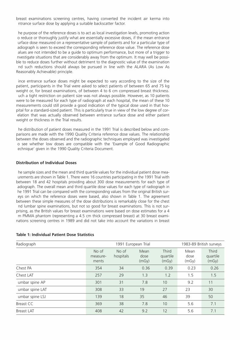
Distribution of Individual Doses
he sample sizes and the mean and third quartile values for the individual patient dose mea-urements are shown in Table 1. There were 16 countries participating in the 1991 Trial with
between 18 and 42 hospitals providing about 300 dose measurements for each type ofadiograph. The overall mean and third quartile dose values for each type of radiograph inhe 1991 Trial can be compared with the corresponding values from the original British sur-eys on which the reference doses were based, also shown in Table 1. The agreement
between these simple measures of the dose distributions is remarkably close for the chestnd lumbar spine examinations, but not so good for breast examinations. This is not sur-
prising, as the British values for breast examinations were based on dose estimates for a 4m PMMA phantom (representing a 4.5 cm thick compressed breast) at 30 breast exami-
nations screening centres in 1989 and did not take into account the variations in breast
Table 1: Individual Patient Dose Statistics
Radiograph 1991 European Trial 1983-89 British surveys
No of No of Mean Third Mean Thirdmeasure- hospitals dose quartile dose quartile
ments (mGy) (mGy) (mGy) (mGy)
Chest PA 354 34 0.36 0.39 0.23 0.26
Chest LAT 257 29 1.3 1.2 1.5 1.5
umbar spine AP 301 31 7.8 10 9.2 11
umbar spine LAT 308 33 19 27 23 30
umbar spine LSJ 139 18 35 46 39 50
Breast CC 369 38 7.8 10 5.6 7.1
Breast LAT 408 42 9.2 12 5.6 7.1

thickness seen in practice. Participants in the Trial were asked to select patients with com-pressed breast thickness between 4 and 6 cm, and in fact achieved this for 90% of thepatients. There was a slight tendency for breasts to be thicker when compressed laterally(mean thickness = 5.3 cm) than when compressed cranio-caudally (mean thickness 5.1 cm).
Comparison of Hospital Mean Doses With Reference Dose Values
The range of the hospital mean doses for each type of radiograph and the percentage ofhospitals for which the mean dose exceeded the corresponding 1990 Quality Criteria ref-erence dose value are shown in Table 2. It can be seen that the mean doses range overfactors of between 5 and 17 depending on the type of radiograph, with PA chests show-ing the lowest spread. Table 2 also shows that between 14 and 69% of hospitals in theTrial have mean dose values in excess of the 1990 Quality Criteria reference values. In theearlier surveys, on which the reference dose values were based, the corresponding figurewas, of course, 25%. Lateral chest and lateral lumbar spine radiographs in the 1991 Trialshow an improvement on this earlier figure whereas the other chest and lumbar spineprojections show a slightly worse performance. These relatively small differences in per-formance observed in a fairly small sample of hospitals are not thought to provide suffi-cient evidence for changing the reference dose values for these two types of examination.
However, for the breast radiographs, over half the hospitals in the 1991 Trial exceeded thereference dose values. The reference dose for breast radiographs consequently needsrevising to a higher value to allow for the variations in breast thickness and the averagethickness higher than 4.5 cm, encountered in a sample of patients when they are select-ed to be within the most commonly occurring range of 4 to 6 cm.
The third quartile values for the hospital mean entrance surface doses are 9 mGy for thecranio-caudal projection and 12 mGy for the lateral projection (close to the correspond-ing third quartile values for the individual entrance surface dose measurements of 10mGy for the cranio-caudal projection and 12 mGy for the lateral projection shown in Table1). Consequently, the 1991 Trial lends support to a new reference value for directly mea-sured breast entrance surface doses on patients of about 10 mGy for either projection(Fig. 3).
There is no need for the reference dose values to be precise or specific as they are intend-ed to act as a trigger to investigation and corrective action only for situations in mosturgent need of better quality control. A rounded value of 10 mGy for both projections istherefore considered to be suitable.
The European Protocol on Dosimetry in Mammography (Zoetelief et al. (1996)) also rec-ommends a reference Entrance Surface Air Kerma (ESAK) of 10 mGy for the mean of 10measurements made on a sample of patients with breast thickness of between 4 and 6cm. ESAK is defined in the Protocol as not to include backscattered radiation from the
Table 2: Compliance with 1990 Quality Criteria Reference Dose Levels
Radiograph 1990 Quality Hospital mean dose values Hospitals withCriteria mean dose
Reference Dose Range Ratio > Reference Dose(mGy) (mGy) max/min (%)
Chest PA 0.3 0.1-0.5 5 29
Chest LAT 1.5 0.3-3.2 11 14
umbar spine AP 10 2-20 10 26
umbar spine LAT 30 4-54 14 15
umbar spine LSJ 40 10-80 8 33
Breast CC 7 2-22 11 53
Breast LAT 7 1.5-2.6 17 69

patient, and is consequently derived from the measured entrance surface dose by divid-ng by an appropriate backscatter factor. However, the backscatter factor is typically onlybout 1.09 for breast examinations, so that the difference between the measuredntrance surface dose and the ESAK is considered to be insufficient to warrant numeri-ally different reference values for the two quantities.
Relationship Between Patient Dose and Radiographic Technique
or each type of radiographic examination included in the 1990 Quality Criteria there isn Example of Good Radiographic Technique in which values are recommended for a list
of radiographic technique parameters which should enable the image and dose criteria tobe met. Those radiographic technique parameters which, if acting independently, wouldbe expected to have an effect on patient entrance surface doses, are:
— speed class of the screen film system;
— radiographic voltage ;
— total filtration;
— focus-to-film distance (FFD);
— type of anti-scatter grid;
— automatic exposure control (AEC) or manual;
he information collected in the 1991 Trial on these technique parameters was analysed toee if their impact on patient entrance surface dose could be observed. Unfortunately, it
was not possible to observe the effect of each parameter independently, by selecting sub-ets of the data in which the effects of all other confounding factors had been removed by
holding their values constant, without reducing the sample to an insignificantly small size.nstead, all the available data for each type of radiograph were analysed together by plot-ing scatter diagrams and calculating the correlation coefficients between the entrance sur-ace doses and the first four of the technique factors listed above. However, little correla-ion was evident in the scatter diagrams and the correlation coefficients were low; most
being below 0.2 and sometimes of the opposite sign to that expected; no doubt due to theonfounding influence of other parameters. There was a disappointingly low correlationeen, for example, between the nominal speed class of the screen film system and dose forll projections, and the expected relationship between radiographic voltage and dose was
only apparent to a slight degree for the chest radiographs.
Ent
ranc
e su
rfac
e do
se
Compressed breast thickness (cm)
(mGy)
number of films = 346correlation coefficient r = 0.31solid line: best fit regression line to data points
0
10
20
30
40
50
60
86420
Figure 3: Scatter diagram of entrance surface dose for different compressed breast thicknesses.(Lateral projection)

An analysis of the technique parameters used by the hospitals at the top and bottom ofthe dose distributions did, however, reveal some clear causes for their bad or good per-formance. For example, the highest dose hospital for PA chest radiographs was using anexceptionally low level of tube voltage (mean value = 49 kV) together with a low FFD of100 cm. The lowest dose hospital for PA chest used a fast screen film system (800) togeth-er with a high tube voltage (mean value = 125 kV) and the second lowest dose hospitalused the longest FFD recommended in the 1990 Quality Criteria Document (200 cm). Forthe AP and lateral lumbar spine projections, one of the highest dose hospitals was usinga slower nominal speed class of the screen film system than recommended in the 1990Quality Criteria and another was using a lower than recommended tube voltage. The low-est dose hospital for the AP lumbar spine projection used the highest FFD of all hospitalsin the Trial (130 cm) and all its other technique parameters were within recommended lev-els. For the lumbo-sacral joint (LSJ) projection the highest dose hospital used a lower thanrecommended tube voltage (mean = 73 kV).
However, no consistent trends were seen in the mean entrance surface dose as a functionof the number of the radiographic technique criteria in the 1990 Quality Criteria whichwere fulfilled. There was, however, clear evidence that higher doses were obtained whenthere was little or no compliance with the criteria given in the Example of GoodRadiographic Technique (Fig. 4).
CONCLUSIONS
The distribution of patient doses measured in the 1991 Trial, from 83 X-ray departmentsin Europe, is sufficiently similar to that seen in earlier surveys for the chest and lumbarspine projections not to warrant any changes in the relevant reference dose values. Forbreast examinations, on the other hand, entrance surface doses measured in the Trial onrepresentative samples of patients, were sufficiently different from those derived in thepast from standard phantom measurements to warrant a revision in the reference dosevalue from 7 mGy to 10 mGy.
It is difficult to observe the influence of individual radiographic technique parameters onpatient entrance surface dose in surveys of this nature which were not designed primari-ly with this purpose in mind. The Trial has demonstrated, however, that the meanentrance surface dose to a representative sample of patients for a particular typeof radiograph, provides a useful measure of the level of patient protectionachieved in an X-ray department and that there still exist wide variations in per-formance throughout Europe.
There was, moreover, clear evidence from the limited analyses performed that it was notdifficult to meet the entrance surface dose criteria in the 1990 Quality Criteria for chestand lumbar spine radiography, while complying with the Example of Good RadiographicTechnique. Conversely, many hospitals failing to meet the dose criteria were found not tobe following the Example of Good Radiographic Technique in its entirety. In particular,increasing the nominal speed class of the screen film system, the radiographic voltage andthe FFD to the upper values given in the Example of Good Radiographic Technique willgenerally result in lower doses to the patient while retaining satisfactory image quality.
Mea
n en
tran
ce s
urfa
ce d
ose
Number of technical criteria fulfilled
(mGy)
0
10
20
30
54321
9.26+10.9-
18.71+10.7 -
14.7+8.64-
29.29+17.70-
22.1+5.95-
0
Figure 4: Impact of good radiographic technique on entrance surface dose.(Lateral Lumbar Spine)

PART 3 — IMAGE QUALITY
One of the most important objectives of the 1991 Trial was to validate and demonstratehe usefulness of the image criteria, for the chest, lumbar spine and breast examinations,elected from the 1990 Quality Criteria Working Document.
n order to achieve this goal, a panel of 15 independent European radiologists (five radi-ologists for each examination) met for one week and reviewed the original X-ray films col-ected during the Trial. In this way, they provided independent analysis of the image qual-ty of these examinations using the same Quality Criteria and questionnaires which hadbeen used by the field radiologists (see Chapter 3: Quality Criteria Implementation andAudit Guidelines). Each member of the panel, working separately, received sets of filmswhich were reorganized randomly between each reading. The panel members completeds many film readings as possible within the week, with the objective of eventually review-
ng all collected films in their particular speciality (chest, lumbar spine or breast). Thus eachilm was checked once on a local level, and from two to five times by independent paneladiologists.
RESULTS AND DISCUSSION
Relevance of the Image Criteria
he compliance rates with the 1990 Quality Criteria for each type of film as assessed byboth the field and panel radiologists are presented in Table 3.
As can be seen, the greater the number of criteria to be met then, generally, the lowerhe percentage of films which met all of them. Thus the PA chest projection with nine riteria showed the lowest percentage of films meeting all criteria for both field and paneladiologists.
However, the fact is that, overall, a high percentage of criteria were met (see final column,able 3). Thus all films met between 85.8% and 93% of criteria. The 5th and 6th columns
of Table 3 indicate that between 33% and 81% of films met all criteria. The criteria are,herefore, not only visible, but the field as well as the panel radiologists confirmed thathey saw most of them.
Obviously, it is important to know whether or not all the panel radiologists saw the sameriteria in that subset of films which had been viewed independently by them all (inter-
Table 3: Compliance Rates with the Image Criteria of the 1990 Quality Criteria
xamination Projection Number Number Films meeting all Image Criteriaype of films of Image Image Criteria met by all films
Criteria (%) as assessed by field
radiologists (%)Field Panel
Radiologists Radiologists
Chest PA 364 9 33.1 35.2 85.8
Lateral 267 4 80.8 80 93
umbar Spine AP/PA 305 7 57.3 59.2 89.2
Lateral 312 7 53.6 51.4 87.4
LSJ 161 4 70.9 70.8 91.9
Breast CC 320 4 72.9 79.3 91.3
Lateral 359 4 67.8 64.3 89.6

viewer reliability). Also, it is important to compare the average response rates of the panelradiologists to those of the field radiologists (inter-group reliability). These considerationsare fundamental in attempting to define relevant and universally applicable criteria.Perfect agreement between the panel and field radiologists would indicate that bothgroups define and apply the criteria in the same way. It would also demonstrate that bothgroups see the criteria in a similar manner, a matter of experience and training. On theother hand, disagreement between the two groups may indicate:
• there is some disagreement about the actual definition of one or more criteria
• judgement is subjective rather than according to stable decision rules common to all
• one group has insufficient experience or training in scoring a criterion reliably
Inter-Viewer Reliability
In order to test the inter-viewer reliability of the panel radiologists, comparisons weremade between their five readings of each projection and examination. In order to ensurethat the viewing conditions were strictly comparable amongst the panel of viewers, newmatched viewing boxes were employed. The inter-viewer reliability is considered sepa-rately for each examination before drawing general conclusions.
Chest
The panel radiologists’ scores for the chest PA projection showed considerably greatervariation than either the lumbar spine or breast assessments. There was a high level ofagreement on only one third of the criteria, namely:
• performed at deep inspiration and with suspended respiration
• reproduction of the vascular pattern in the whole lung, particularly in the peripheralvessels
• visually sharp reproduction of the trachea and proximal bronchi, the borders of theheart and aorta.
It can be recognized that the first criteria concerns the positioning of the patient and co-operation, while the other two depend to a large extent upon the radiographic techniqueitself; field size (second) and resolution (third).
For the remaining criteria there was significant disagreement with up to 100% on certaincriteria. The disagreement highlighted a number of revealing problems associated withthe criteria:
• judgments relating to degree of symmetry and/or completeness, for example:
— symmetrical reproduction of the thorax
— reproduction of the whole rib cage above the diaphragm;
• assessments of technical prowess including good positioning and choice of kV, expo-sure time etc., for example:
— visualization of the retrocardiac lung and mediastinum.
The panel members also made a subjective assessment of film blackening and the chestimages with non-optimal scores for the Image Criteria tended also to be assessed as beingtoo dark. However, roughly 70% of all the chest images were deemed to be of optimalfilm density.
When comparing the panel and field radiologists, both groups scored films similarly.However, the greatest level of disagreement concerned the criterion:

symmetrical reproduction of the thorax.
he only two criteria for which there was agreement between the assessments of bothgroups were:
performed at deep inspiration and with suspended respiration;
visually sharp reproduction of the trachea and proximal bronchi, the borders of theheart and aorta.
he lateral projection is a non-routine examination normally used to confirm findings ofhe PA view. Fewer Image Criteria are employed since less information is normally gath-red from this image. Nevertheless, results for this projection were, in essence, similar tohose noted for the PA projection.
umbar Spine
here were seven Image Criteria for either the AP or PA views when film blackening wasncluded. The panel members agreed that 80% or more of all films fulfilled four out ofhe six anatomical Image Criteria. However, there was considerable disagreement on the
other two criteria:-
visually sharp reproduction of the pedicles;
visualization of the intervertebral joints.
Visualization of the intervertebral joints and reproduction of the spinous and transverseprocesses depend upon careful positioning of the patient, which is not always easy tochieve.
he criterion:
reproduction of the adjacent soft tissues, particularly the psoas shadow
s also difficult to visualize, even on a perfect image. Therefore, it is perhaps not surprisinghat ‘average’ compliance among the panel members for this criterion was roughly 85%,omewhat less than the overall Image Criteria compliance of 89% shown in Table 3.
n respect of film blackening, the panel members tended to prefer a darker film, in gen-ral, in order to ensure adequate contrast between different bony structures. Hence, non-
optimal films were predominantly considered to be too light. Far fewer films, approxi-mately 60%, were considered optimal for this projection. It was interesting to note thatgenerally there was again little disagreement between the average responses of the panelnd field radiologists.
or the lateral projection, the same pattern of responses was found for those criteria inommon with the AP or PA projections. However, for three criteria, there was consider-ble disagreement among the panel members on the degree to which films fulfilled theriteria. For the criterion:
full superposition of the posterior vertebral edges
cceptability ranged between 35 and 90% among the panel members in terms of per-entage of films fulfilling the criterion. Obviously, the panel members had to apply their
own personal definition of ‘full’. This type of problem eventually led the panel memberso devise a scoring mechanism for individual criteria analogous to that often applied inisual detection tests. (See Chapter 3).

The criterion:
• visually sharp reproduction of the cortex and trabecular structures
received the lowest compliance rating of all the criteria for this projection for all panelmembers (on average approximately 72%).
Also, on average, even fewer films were considered to be of optimal optical (film) densi-ty for this view (only approximately 50%). All panel members, on average, considered thatroughly 42% of films were too light.
The panel and field radiologists showed generally good agreement for most criteria.However, the field radiologists in this projection tended to find that criteria were fulfilleda little more often. In the case of an assessment of film blackening, the field radiologistsdeemed radiographs to be of optimal film density in 75% of cases on average, whereasthe panel assessed only 50% to be in this category.
The lateral projection of the lumbo-sacral joint is, in general, a less frequent projectionused to confirm the findings of the other two projections. There are, therefore, fewer cri-teria to be met. However, in general, the criterion:
• reproduction by tangential projection of the inferior end plate of the L5 and the supe-rior end plate of S1
was only deemed to be met on average in approximately 80% of films. This criterion isdependent to a large extent upon careful positioning of the patient. The remaining twocriteria were deemed to be fulfilled in a high percentage of cases. But again, on average,only roughly 75% of images were deemed to be of optimum film density.
For this projection there was good agreement between panel and field radiologists assess-ments.
Breast
The panel radiologists showed almost perfect agreement for the first two criteria of thecranio-caudal projection image. For the third criterion:
• nipple should be parallel to the film
the inter-viewer variability was large (40-80%) among the panel members. Also, the aver-age acceptability (67%) for this criterion, among the whole panel, was poor. It wouldappear that this criterion is too vague, since strict parallelism is hard to verify.
In respect of optimal film blackening, approximately 75% of films were, on average,deemed to be of optimal film density, with the remaining 25% assessed as being toolight.
For this projection, the panel radiologists generally assessed criteria as being fulfilled morefrequently than the field radiologists, including strict parallelism of the nipple. However,for the lateral view, the reverse situation existed.
CONCLUSIONS
The results of the 1991 Trial of the 1990 Quality Criteria highlighted a number of impor-tant aspects concerning the assessment of image quality by means of Image Criteriaemploying anatomical details.
1. Radiologists find it difficult to unequivocally interpret criteria which:

involve some form of assessment of symmetry, for example symmetrical reproductionof the thorax
involve assessment of field coverage, for example reproduction of the whole rib cageabove the diaphragm
involve assessment of fulfilment of technical requirements, for example visualisation ofthe retrocardiac lung and the mediastinum.
2. The set of Image Criteria defined for evaluation of the quality of diagnostic films forthe chest, lumbar spine and breast examinations in general could be applied consis-tently by both a panel of expert radiologists and those working in the field.
3. Seven out of 29 criteria failed to meet validation requirements for inter-viewer reliabil-ity. Three types of weakness were indicated:
definition was too vague, employing words such as ‘full’ and ’symmetric’ without pro-viding limits of acceptable deviation or any measurement technique
criteria are non-exclusive whereby categories of response could be interpreted in atleast two ways
criterion such as film blackening is rather subjective and produced a highly variableassessment.
4. Clearer compartmentalization of Image Criteria into positioning and technical cate-gories is required in order to more easily link the image quality, patient dose and radi-ographic technique.
All of these observations have been taken into account in the revised lists of QualityCriteria presented in Chapter 1.

LIST OF REFERENCES FOR CHAPTER 2
CEC (1987) ‘Quality Criteria for Diagnostic Radiographic Images’, 1st edition, April 1987,Working Document XII/252/87 (CEC, Brussels).
CEC (1990) ‘Quality Criteria for Diagnostic Radiographic Images’, 2nd edition June 1990,Working Document XII/173/90 (CEC, Brussels).
EN/IEC (1993) ‘Medical Electrical Equipment Part 2: Particular Requirements for the Safetyof X-ray Source Assemblies and X-ray Tube Assemblies for Medical Diagnosis’. EN/IEC60601-2-28, CENELEC, Central Secretariat, Rue de Stassart 35, B-1050 Brussels.
Moores B. M., Henshaw E. T., Watkinson S. A. and Pearcy B. J. (1987), Practical Guide toQuality Assurance in Medical Imaging, John Wiley and Sons, Chichester, England.
Maccia C., Wall B. F., Padovani R., Shrimpton P. C. and Husson B. (1989), ‘Results of a TrialSet Up by a Study Group of the Radiation Protection Programme of the CEC’. InOptimization of Image Quality and Patient Exposure in Diagnostic Radiology. BIR Report20, edited by Moores B. M., Wall B. F., Eriskat H. and Schibilla H. British Institute ofRadiology, London.
Maccia C., Moores B. M., Nahrstedt U., Padovani R., and Wall B. F. (1990). ‘CEC QualityCriteria for Diagnostic Radiographic Images and Patient Exposure Trial’, Report EUR 12952(CEC, Brussels).
Shrimpton P. C., Wall B. F., Jones D. G., Fisher E. S., Hillier M. C., Kendall G. M. andHarrison R.M. (1986). A National Survey of Doses to Patients Undergoing a Selection ofRoutine X-ray Examinations in English Hospitals, NRPB-R200 (London, HMSO).
Warren-Forward H. M. and Bradley D. A. (1993) ‘A pilot study of chest X-ray doses anddose variability within the West Midlands Regional Health Authority’., Journal ofRadiological Protection, Vol. 13 No 4, pp. 267-274.
Maccia, C., Moores, B. M., Wall, B. F. (1996), ‘The 1991 Trial on Quality Criteria forDiagnostic Radiographic Images, Detailed Results and Findings’, Report EUR 16635,(Office for Official Publications of the European Communities, Luxembourg) in press.
Zoetelief, J., Fitzgerald, M., Leitz, W. and Säbel, M. (1996), ‘European Protocol onDosimetry in Mammography’ Report EUR 16263, (Office for Official Publications of theEuropean Communities, Luxembourg).

Chapter 3
QUALITY CRITERIA IMPLEMENTATION AND AUDIT GUIDELINES
TABLE OF CONTENTS
QUALITY CRITERIA IMPLEMENTATION AND AUDIT GUIDELINES 48
APPENDIX I Sample Questionnaire for Recording Radiographic
Technique, Equipment and Dose Data 51
APPENDIX II Image Quality Assessment Forms 51
Chest
Skull
Lumbar Spine
Pelvis
Urinary Tract
Breast

Quality Criteria Implementation and Audit Guidelines
The Quality Criteria are designed to be easily applied in practice in any X-ray departmentwithout the need for special equipment apart from a means of measuring or estimatingthe dose to the patient. They are intended to provide a demonstrably achievable standardof good practice both in terms of a satisfactory level of image quality and an acceptablylow radiation dose to the patient.
However, the Quality Criteria will only be of real benefit to an X-ray department if theyallow inadequate levels of performance to be readily identified and corrected. The impactof applying the Quality Criteria in a particular X-ray department in terms of the level ofimprovement in performance achieved, can only be properly assessed through a correctlystructured process of medical audit.
The essential components of the medical audit process can be summarized as:
— Set standards
— Check compliance
— Correct bad practice
— Set new standards
— Repeat.
The Quality Criteria essentially provide the initial ’standards’ for image quality and patientdose audit: a special case of ‘medical’ audit.
More detailed steps in the audit process specific to this special case are:
1. Choose a type of radiograph and X-ray facility (room or individual X-ray unit) to audit.
2. Take a random sample of at least 10 standard-sized patients (60-80 kg or 4-6 cmbreast thickness).
3. Take the chosen type of radiograph on each patient using established techniques.
4. Record all the technique and equipment parameters for each radiograph. (See exam-ple questionnaire in Appendix I to this chapter for relevant details to record.)
5. Measure or estimate the entrance surface dose for each radiograph using the meth-ods described in Appendix I of Chapter 1. Compare the mean value for the sample ofat least 10 standard-sized patients with the corresponding reference dose value in theQuality Criteria.
6. At least two observers should check compliance of each radiograph with the ImageCriteria independently. Appendix II to this chapter contains copies of the Image CriteriaAssessment forms used by the panel radiologists for scoring films in the trials of theQuality Criteria. Observers taking part in this audit process might find these forms use-ful. There is a form or set of forms for each type of radiograph for which QualityCriteria are provided in these Guidelines. As well as providing a system for scoringcompliance with the Image Criteria and the visibility of important image details, theseforms also include a system for scoring more general aspects of the image, such asblackening, contrast, sharpness, beam limitation and diagnostic acceptability.
To help in judging these features, both during this audit process and moregenerally at any time, X-ray departments should consider having available aset of ‘ideal’ films in which all these aspects are optimized and against whichany other films can be directly visually compared. It is essential, of course, thatthe ‘ideal’ film can be produced with a dose to the patient below the corre-sponding reference value.

7. Identify where the standard (image quality or dose criteria) are not being met.
8. Investigate the cause(s) of any consistent non-compliance with the criteria. The‘Example of Good Radiographic Technique’ may be useful to help identify thoseaspects of the established technique or equipment which are responsible.
9. Take corrective action by changing techniques or equipment in a manner likely to rem-edy the non-compliance.
10.After a short period of using the revised techniques or equipment, repeat steps 2-7.
11.If no improvement, repeat steps 7-10.
12.If initial standards (Quality Criteria) are now being met in full, consider improving stan-dards, for example, by setting lower reference dose values in line with the optimiza-tion principle ALARA (As Low as Reasonably Achievable).
o help establish a more uniform and more widespread level of performance in diagnos-ic radiology, it would be desirable to extend the audit process to include independent
observers, external to the X-ray department being audited, and to progressively apply theprocess to larger groupings than individual X-ray departments.


Chest Examination
CHAPTER 3
APPENDIX I
SAMPLE QUESTIONNAIRE FOR
RECORDING RADIOGRAPHIC TECHNIQUE, EQUIPMENT AND DOSE DATA

QUESTIONNAIRE CHEST, LUNGS AND HEART
A) Radiographic Technique u to be filled in by the radiographer
A.1. Is the examination performed on:
• Vertical stand with stationary grid . . . . . . . . . . . . . . . . . . . . . . . . . . . . . . . . . . . . . . . . . . . . . . . . . . . .
• Vertical stand with moving grid . . . . . . . . . . . . . . . . . . . . . . . . . . . . . . . . . . . . . . . . . . . . . . . . . . . . . .
• Other:
A.2. X-ray Generator
• Manufacturer/Type: /
• Wave form: 6 Pulse . . . . . . . . . . . . . . . 12 Pulse . . . . . . . . . . . . . . . . .
Constant Potential . . . . . . . Capacitor Discharge . . . . . . . . .
Other:
A.3. X-Ray tube
• Manufacturer/Type: /
• Inherent filtration mm Al equivalent
mm Cu equivalent
mm other equivalent
mm mm
• Nominal focal spot values
• Is the X-ray unit equipped with
an Automatic exposure control ? Yes No
an Anti-scatter grid? Yes No
If Yes, Grid ratio ‘r‘? Strips per cm?
A.4. Screen-Film System
• Film Manufacturer/Type: /
• Screen Manufacturer/Type: /
In use since (date)
A.5. Film Processor
• Manufacturer/Type: /
• Processing Time: s
• Developer Temperature: °C
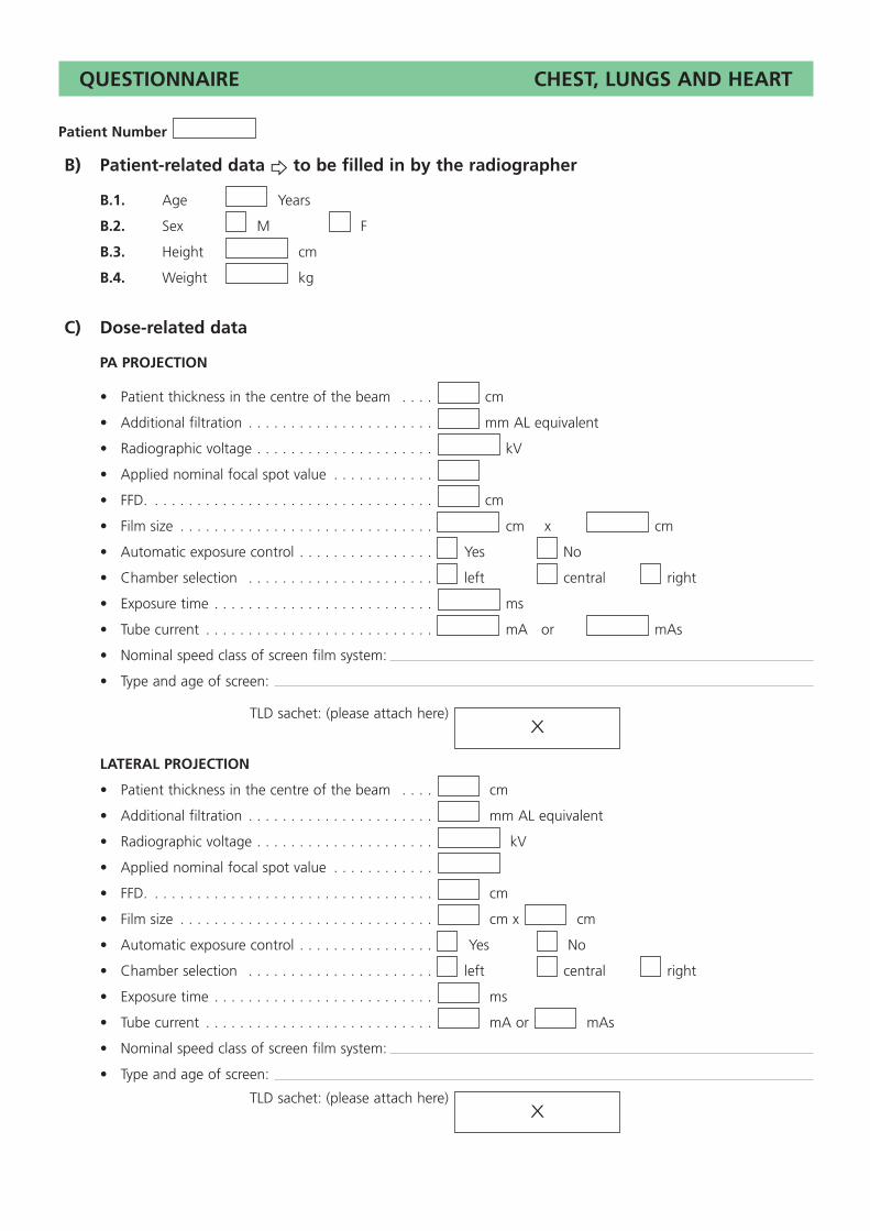
QUESTIONNAIRE CHEST, LUNGS AND HEART
Patient Number
B) Patient-related data u to be filled in by the radiographer
B.1. Age Years
B.2. Sex M F
B.3. Height cm
B.4. Weight kg
C) Dose-related data
PA PROJECTION
• Patient thickness in the centre of the beam . . . . cm
• Additional filtration . . . . . . . . . . . . . . . . . . . . . . mm AL equivalent
• Radiographic voltage . . . . . . . . . . . . . . . . . . . . . kV
• Applied nominal focal spot value . . . . . . . . . . . .
• FFD. . . . . . . . . . . . . . . . . . . . . . . . . . . . . . . . . . cm
• Film size . . . . . . . . . . . . . . . . . . . . . . . . . . . . . . cm x cm
• Automatic exposure control . . . . . . . . . . . . . . . . Yes No
• Chamber selection . . . . . . . . . . . . . . . . . . . . . . left central right
• Exposure time . . . . . . . . . . . . . . . . . . . . . . . . . . ms
• Tube current . . . . . . . . . . . . . . . . . . . . . . . . . . . mA or mAs
• Nominal speed class of screen film system:
• Type and age of screen:
TLD sachet: (please attach here)
LATERAL PROJECTION
• Patient thickness in the centre of the beam . . . . cm
• Additional filtration . . . . . . . . . . . . . . . . . . . . . . mm AL equivalent
• Radiographic voltage . . . . . . . . . . . . . . . . . . . . . kV
• Applied nominal focal spot value . . . . . . . . . . . .
• FFD. . . . . . . . . . . . . . . . . . . . . . . . . . . . . . . . . . cm
• Film size . . . . . . . . . . . . . . . . . . . . . . . . . . . . . . cm x cm
• Automatic exposure control . . . . . . . . . . . . . . . . Yes No
• Chamber selection . . . . . . . . . . . . . . . . . . . . . . left central right
• Exposure time . . . . . . . . . . . . . . . . . . . . . . . . . . ms
• Tube current . . . . . . . . . . . . . . . . . . . . . . . . . . . mA or mAs
• Nominal speed class of screen film system:
• Type and age of screen:
TLD sachet: (please attach here)X
X

Chest
Skull
Lumbar Spine
Pelvis
Urinary Tract
Breast
CHAPTER 3
APPENDIX II
IMAGE QUALITY ASSESSMENT FORMS

Performed at full inspiration (as assessed by the position of the ribs above the diaphragm — either 6 anteriorly or 10 posteriorly) and with suspended respiration
Symmetrical reproduction of the thorax, as shown by the central position of a spinous process between the medial ends of the clavicules
Medial border of the scapulae to be outside the lung fields
Reproduction of the whole rib cage above the diaphragm
Visually sharp reproduction of the vascular pattern of the lungs, particularlythe peripheral vessels
Visually sharp reproduction of the:
(a) trachea and proximal bronchi
(b) borders of the heart and the aorta
(c) diaphragm and lateral costo-phrenic angles
Visualization of the retrocardiac lung and the mediastinum
Visualization of the spine through the heart shadow
Total:
Name of radiologist:Hospital code:
Patient No: Image criteria *
Important image details **
1 2 3 4 5 6 7 8 9 10 11 12 13 14 15
Scoring: * 1: yes; 0: no; where any area is obscured by a pathological condition, then ‘P’ should be placed in the appropriate box.
Maximum total score: 10.
** +: yes; if ‘no’ indicate minimum visible detail (in mm).
Small round details in the whole lung, including the retrocardiac areas:high contrast: 0.7 mm; low contrast: 2 mm diameter
Linear and reticular details out to the lung periphery:high contrast: 0.3 mm; low contrast: 2 mm in width

Performed at full inspiration and with suspended respiration
Arms should be raised clear of the thorax
Superimposition of the posterior lung borders
Reproduction of the trachea
Reproduction of the costo-phrenic angles
Visually sharp reproduction of the:
(a) posterior border of the heart and the aorta
(b) mediastinum
(c) diaphragm
(d) sternum
(e) thoracic spine
Total:
Name of radiologist:Hospital code:
Patient No: Image criteria *
Important image details **
1 2 3 4 5 6 7 8 9 10 11 12 13 14 15
Scoring: * 1: yes; 0: no; where any area is obscured by a pathological condition, then ‘P’ should be placed in the appropriate box.
Maximum total score : 10.
** +: yes; if ‘no’ indicate minimum visible detail (in mm).
Small round details in the whole lung:high contrast: 0.7 mm; low contrast: 2.0 mm diameter
Linear and reticular details out to the lung periphery :high contrast: 0.3 mm; low contrast: 2.0 mm in width

Appropriate film density (blackening): Lungs*
Appropriate film density (blackening): mediastinum*
Contrast **
Sharpness ***
Appropriate beam limitation ****
Film acceptability *****
Name:Hospital code:Complete image annotation (see p.4) must be available on each film
Patient No:
1 2 3 4 5 6 7 8 9 10 11 12 13 14 15
1. Comments specific to an individual film:
2. General comments on a group of films from one source:
Scoring:
* Film density: +: optimum; X: too much; Y: too little
** Contrast: +: optimum; X : too high; Y : too low
*** Sharpness: +: optimum; Y: sub-optimum; 0: unacceptable
**** Beam limitation: +: optimum; X: field size too large; Y: field size too small
***** Film acceptability: 1 = fully acceptable; 2 = probably acceptable; 3 = only acceptable under limited clinical conditions; 4 = unacceptable (give reasons)
Film No Not accepted because of:

Symmetrical reproduction of the skull, particularly cranial vault, orbits andpetrous bones
Projection of the apex of the petrous temporal bone into the centre of theorbits
Visually sharp reproduction of:
(a) the frontal sinus and ethmoid cells
(b) the apex of the petrous temporal bones
(c) the internal auditory canals
Visually sharp reproduction of the outer and inner lamina of the cranial vault
Total:
Name of radiologist:Hospital code:
Patient No: Image criteria *
Important image details **
1 2 3 4 5 6 7 8 9 10 11 12 13 14 15
Scoring: * 1: yes; 0: no; where any area is obscured by a pathological condition, then ‘P’ should be placed in the appropriate box.
Maximum total score : 6.
** +: yes; if ‘no’ indicate minimum visible detail (in mm).
0.3-0.5 mm

Visually sharp reproduction of:
(a) the outer and inner lamina of the cranial vault
(b) the floor of the sella
(c) the apex of the petrous temporal bone
Superimposition respectively of the contours of:
(a) the frontal cranial fossa
(b) the lesser wing of the sphenoid bone
(c) the clinoid processes
(d) the external auditory canals
Visually sharp reproduction of:
(a) the vascular channels
(b) the vertex of the skull
(c) the trabecular structure of the cranium
Superimposition of the mandibular angles and ascending rami
Total:
Name of radiologist:Hospital code:
Patient No: Image criteria *
Important image details **
1 2 3 4 5 6 7 8 9 10 11 12 13 14 15
Scoring: * 1: yes; 0: no; where any area is obscured by a pathological condition, then ‘P’ should be placed in the appropriate box.
Maximum total score : 11.
** +: yes; if ‘no’ indicate minimum visible detail (in mm).
0.3-0.5 mm

Appropriate film density (blackening) *
Contrast **
Sharpness ***
Appropriate beam limitation ****
Film acceptability *****
Name:Hospital code:Complete image annotation (see p.4) must be available on each film
Patient No:
1 2 3 4 5 6 7 8 9 10 11 12 13 14 15
1. Comments specific to an individual film:
2. General comments on a group of films from one source:
Scoring:
* Film density: +: optimum; X: too much; Y: too little
** Contrast: +: optimum; X : too high; Y : too low
*** Sharpness: +: optimum; Y: sub-optimum; 0: unacceptable
**** Beam limitation: +: optimum; X: field size too large; Y: field size too small
***** Film acceptability: 1 = fully acceptable; 2 = probably acceptable; 3 = only acceptable under limited clinical conditions; 4 = unacceptable (give reasons)
Film No Not accepted because of:

Visually sharp reproduction of the upper and lower-plate surfaces,represented as lines in the centred beam area
Visually sharp reproduction of the pedicles
Reproduction of the intervertebral joints
Reproduction of the spinous and transverse processes
Visually sharp reproduction of the cortex and trabecular structures
Reproduction of the adjacent soft tissues, particularly the psoas shadows
Reproduction of the sacro-iliac joints
Total:
Name of radiologist:Hospital code:
Patient No: Image criteria *
Important image details **
1 2 3 4 5 6 7 8 9 10 11 12 13 14 15
Scoring: * 1: yes; 0: no; where any area is obscured by a pathological condition, then ‘P’ should be placed in the appropriate box.
Maximum total score: 7.
** +: yes; if ‘no’ indicate minimum visible detail (in mm).
Image detail at 3rd lumbar vertebral body: 0.3-0.5 mm in width

Visually sharp reproduction of the upper and lower-plate surfaces,represented as lines with the resultant visualization of the intervertebralspaces
Full superimposition of the posterior vertebral edges
Reproduction of the pedicles and intervertebral foramina
Visualization of the spinous processes
Visually sharp reproduction of the cortex and trabecular structures
Total:
Name of radiologist:Hospital code:
Patient No: Image criteria *
Important image details **
1 2 3 4 5 6 7 8 9 10 11 12 13 14 15
Scoring: * 1: yes; 0: no; where any area is obscured by a pathological condition, then ‘P’ should be placed in the appropriate box.
Maximum total score: 5.
** +: yes; if ‘no’ indicate minimum visible detail (in mm).
Image details at 3rd lumbar vertebral body, ventral edge: 0.5 mm in width

Reproduction by tangential projection of the inferior end plate of L5 andthe superior end plate of S1
Visualization of the spinous process of L5
Visualization of the anterior border of the upper sacrum
Reproduction of vertebral pieces of the upper sacrum
Total:
Name of radiologist:Hospital code:
Patient No: Image criteria *
Important image details **
1 2 3 4 5 6 7 8 9 10 11 12 13 14 15
Scoring: * 1: yes; 0: no; where any area is obscured by a pathological condition, then ‘P’ should be placed in the appropriate box.
Maximum total score: 4.
** +: yes; if ‘no’ indicate minimum visible detail (in mm).
Linear and reticular details: 0.5 mm in width

Appropriate film density (blackening): vertebral bone *
Appropriate film density (blackening): soft tissue *
Contrast **
Sharpness ***
Appropriate beam limitation ****
Film acceptability *****
Name Hospital code:Complete image annotation (see p.4) must be available on each film
Patient No:
1 2 3 4 5 6 7 8 9 10 11 12 13 14 15
1. Comments specific to an individual film:
2. General comments on a group of films from one source:
Scoring:
* Film density: +: optimum; X: too much; Y: too little
** Contrast: +: optimum; X : too high; Y : too low
*** Sharpness: +: optimum; Y: sub-optimum; 0: unacceptable
**** Beam limitation: +: optimum; X: field size too large; Y: field size too small
***** Film acceptability: 1 = fully acceptable; 2 = probably acceptable; 3 = only acceptable under limited clinical conditions; 4 = unacceptable (give reasons)
Film No Not accepted because of:

Symmetrical reproduction of the pelvis as judged by the impositionof the symphysis pubis over the midline of the sacrum
Visually sharp reproduction of the sacrum and its intervertebral foramina
Visually sharp reproduction of the pubic and ischial rami
Visually sharp reproduction of the sacroiliac joints
Visually sharp reproduction of the necks of the femora which shouldnot be distorted by foreshortening or rotation
Visually sharp reproduction of the:
(a) spongiosa and corticalis
(b) trochanters
Total:
Name of radiologist:Hospital code:
Patient No: Image criteria *
Important image details **
1 2 3 4 5 6 7 8 9 10 11 12 13 14 15
Scoring: * 1: yes; 0: no; where any area is obscured by a pathological condition, then ‘P’ should be placed in the appropriate box.
Maximum total score: 7.
** +: yes; if ‘no’ indicate minimum visible detail (in mm).
0.5 mm

Appropriate film density (blackening) *
Contrast **
Sharpness ***
Appropriate beam limitation ****
Film acceptability *****
Name:Hospital code:Complete image annotation (see p.3) must be available on each film
Patient No:
1 2 3 4 5 6 7 8 9 10 11 12 13 14 15
1. Comments specific to an individual film:
2. General comments on a group of films from one source:
Scoring:
* Film density: +: optimum; X: too much; Y: too little
** Contrast: +: optimum; X : too high; Y : too low
*** Sharpness: +: optimum; Y: sub-optimum; 0: unacceptable
**** Beam limitation: +: optimum; X: field size too large; Y: field size too small
***** Film acceptability: 1 = fully acceptable; 2 = probably acceptable; 3 = only acceptable under limited clinical conditions; 4 = unacceptable (give reasons)
Film No Not accepted because of :

Reproduction of the area of the whole urinary tract from the upperpole of the kidney to the base of the bladder
Reproduction of the kidneys outlines
Visualization of the psoas outlines
Visually sharp reproduction of the bones
Total:
Name of radiologist:Hospital code:
Patient No: Image criteria *
Important image details **
1 2 3 4 5 6 7 8 9 10 11 12 13 14 15
Scoring: * 1: yes; 0: no; where any area is obscured by a pathological condition, then ‘P’ should be placed in the appropriate box.
Maximum total score: 4.
** +: yes; if ‘no’ indicate minimum visible detail (in mm).
Calcifications: 1.0 mm
Plain film or before administration contrast medium

Increase in parenchymal density (nephrographic effect)
Visually sharp reproduction of the renal pelvis and calyces(pyelographic effect)
Reproduction of the pelvi-ureteric junction
Visualization of the area normally traversed by the ureter
Reproduction of the whole bladder area
Total:
Name of radiologist:Hospital code:
Patient No: Image criteria *
Important image details **
1 2 3 4 5 6 7 8 9 10 11 12 13 14 15
Scoring : * 1: yes; 0: no; where any area is obscured by a pathological condition, then ‘P’ should be placed in the appropriate box.
Maximum total score: 5.
** +: yes; if ‘no’ indicate minimum visible detail (in mm).
Calyceal details : 0.3 mm
Calcifications : 1.0 mm
After administration of contrast medium

Appropriate film density (blackening)*
Contrast **
Sharpness ***
Appropriate beam limitation ****
Film acceptability *****
Name:Hospital code:Complete image annotation (see p.4) must be available on each film
Patient No:
1 2 3 4 5 6 7 8 9 10 11 12 13 14 15
1. Comments specific to an individual film:
2. General comments on a group of films from one source:
Scoring:
* Film density: +: optimum; X: too much; Y: too little
** Contrast: +: optimum; X : too high; Y : too low
*** Sharpness, noise, latitude: +: optimum; Y: sub-optimum; 0: unacceptable
**** Beam limitation: +: optimum; X: field size too large; Y: field size too small
***** Film acceptability: 1 = fully acceptable; 2 = probably acceptable; 3 = only acceptable under limited clinical conditions; 4 = unacceptable (give reasons)
Film No Not accepted because of:

Pectoral muscle at correct angle
Inframammary angle visualized
Visually sharp reproduction of craniolateral glandular tissue
Visually sharp reproduction of retroglandular fat tissue
Nipple in full profile, clear of overlying breast tissue and/or indicated by marker
No skinfolds seen
Symmetrical images of left and right breast
Name of radiologist:Hospital code:
Patient No: Image criteria related to positioning *
Important image details **
1 2 3 4 5 6 7 8 9 10 11 12 13 14 15
Visualization of skin outline with bright light (but barely without it)
Reproduction of vascular structures seen through most dense parenchyma(optical density of no less than 0.5 in most dense parenchyma)
Visually sharp reproduction of all vessels and fibrous strands and pectoralmuscle margin (absence of movement)
Visually sharp reproduction of skin structure (rosettes from pores) alongthe pectoralis muscle
Total:
Image criteria related to exposure parameters * 1 2 3 4 5 6 7 8 9 10 11 12 13 14 15
Scoring: * 1: yes; 0: no; where any area is obscured by a pathological condition, then ‘P’ should be placed in the appropriate box.
Maximum total score: 11.
** +: yes; if ‘no’ indicate minimum visible detail (in mm).
Microcalcifications: 0.2 mm

Visually sharp reproduction of pectoral muscle at image margin
Visually sharp reproduction of retroglandular fat tissue
Visually sharp reproduction of medial breast tissue
Visually sharp reproduction of lateral glandular tissue
No skinfolds seen
Symmetrical images of left and right breast
Name of radiologist:Hospital code:
Patient No: Image criteria related to positioning *
Important image details **
1 2 3 4 5 6 7 8 9 10 11 12 13 14 15
Visualization of skin outline with bright light (but barely without it)
Reproduction of vascular structures seen through most dense parenchyma(optical density of no less than 0.5 in most dense parenchyma)
Visually sharp reproduction of all vessels and fibrous strands and pectoralmuscle margin (absence of movement)
Visually sharp reproduction of skin structure (rosettes from pores) alongthe pectoralis muscle
Total:
Image criteria related to exposure parameters * 1 2 3 4 5 6 7 8 9 10 11 12 13 14 15
Scoring: * 1: yes; 0: no; where any area is obscured by a pathological condition, then ‘P’ should be placed in the appropriate box.
Maximum total score: 10.
** +: yes; if ‘no’ indicate minimum visible detail (in mm).
Microcalcifications: 0.2 mm

Appropriate film density (blackening) *
Contrast **
Sharpness ***
Noise level ***
Latitude (whole tissue density range of breast documented) ***
Maintenance and handling characteristics ****
(a) absence of artefacts in cassette (dust etc.)
(b) absence of processing artefacts
(c) absence of handling artefacts
(d) no visible gridlines
Film acceptability *****
Name:Hospital code:Complete image annotation (see p.4) must be available on each film
Patient No:
1 2 3 4 5 6 7 8 9 10 11 12 13 14 15
1. Comments specific to an individual film:
2. General comments on a group of films from one source:
Scoring:
* Film density: +: optimum; X: too much; Y: too little
** Contrast: +: optimum; X : too high; Y : too low
*** Sharpness, noise, latitude: +: optimum; Y: sub-optimum; 0: unacceptable
**** Maintenance and handling characteristics: +: fulfilled; 0: not fulfilled
***** Film acceptability: 1 = fully acceptable; 2 = probably acceptable; 3 = only acceptable under limited clinical conditions; 4 = unacceptable (give reasons).
Film No Not accepted because of:


hese European Guidelines on Quality Criteria for Radiographic Images result from auropean-wide cooperation between the various professionals and authorities involved in
Diagnostic Radiology.
he services of the European Commission (EC) would like to express their sincere thankso all those mentioned hereafter for their efforts and encouraging support to the
development of the Quality Criteria concept:
First CEC Study Group on Quality Criteria for Radiographic Images
(1986-90)
BROERSE, J. J. . . . . . . Radiobiological Inst, TNO — Rijswijk . . . . . . . . . . . . . . . . . . (NL)
CARMICHAEL, J. H. E. Liverpool . . . . . . . . . . . . . . . . . . . . . . . . . . . . . . . . . . . . . (UK)
CORLOBE, F. . . . . . . . Hôpital Saint Louis — Paris . . . . . . . . . . . . . . . . . . . . . . . . . . (F)
DREXLER, G. . . . . . . . Institut für Strahlenschutz, GSF — Neuherberg . . . . . . . . . . . (D)
LSAKKERS, P. . . . . . . ISSRT — Leiden . . . . . . . . . . . . . . . . . . . . . . . . . . . . . . . . . (NL)
RISKAT, H. . . . . . . . . CEC, DG XI/C/1, Radiation Protection — Luxembourg . . . . . . (L)
ENDEL (+), H. . . . . . . Haunersches Kinderspital, Univ. — Munich . . . . . . . . . . . . . . (D)
AVAL JEANTET, M. . . Hôpital Saint Louis — Paris . . . . . . . . . . . . . . . . . . . . . . . . . . (F)
MACCIA, C. . . . . . . . CAATS — Bourg-la-Reine . . . . . . . . . . . . . . . . . . . . . . . . . . . (F)
MOORES, B. M. . . . . . Integrated Radiological Services Ltd. — Liverpool . . . . . . . . (UK)
ADOVANI, R. . . . . . . Ospedale ’Santa Maria della Misericordia’, USL n° 7 — Udine . (I)
ANZER, W. . . . . . . . . Institut für Strahlenschutz, GSF — Neuherberg . . . . . . . . . . . (D)
CHIBILLA, H. . . . . . . CEC, DG XII/F/6,Radiation Protection Research Action — Brussels (B)
CHMIDT, TH. . . . . . . Klinikum der Stadt Nürnberg — Nuremberg . . . . . . . . . . . . . (D)
TIEVE, F. E. . . . . . . . . Institut für Strahlenschutz, GSF — Neuherberg . . . . . . . . . . . (D)
WALL, B. F. . . . . . . . . National Radiological Protection Board, NRPB — Chilton . . . (UK)
OETELIEF, J. . . . . . . . Radiobiological Inst, TNO — Rijswijk . . . . . . . . . . . . . . . . . . (NL)
Second CEC Study Group on Quality Criteria for Radiographic Images
(1992-95)
CARMICHAEL, J. H. E. Liverpool . . . . . . . . . . . . . . . . . . . . . . . . . . . . . . . . . . . . . (UK)
EONARDI, M. . . . . . . IRCCS, Ospedale Maggiore — Milan . . . . . . . . . . . . . . . . . . . (I)
MACCIA, C. . . . . . . . CAATS — Bourg-la-Reine . . . . . . . . . . . . . . . . . . . . . . . . . . . (F)
MOORES, B. M. . . . . . Integrated Radiological Services Ltd. — Liverpool . . . . . . . . (UK)
OESTMAN, J. W. . . . . Georg August Universität — Göttingen . . . . . . . . . . . . . . . . (D)
ADOVANI, R. . . . . . . Ospedale ’Santa Maria della Misericordia‘, USL n° 7 — Udine . (I)
CHAPTER 4
LIST OF ALL THOSE WHO CONTRIBUTED TO THEESTABLISHMENT, TESTING AND EVALUATION OF THEQUALITY CRITERIA PRESENTED IN THESE GUIDELINES

PANZER, W. . . . . . . . . Institut für Strahlenschutz, GSF — Neuherberg . . . . . . . . . . . (D)
SAURE, D. . . . . . . . . . Hannover . . . . . . . . . . . . . . . . . . . . . . . . . . . . . . . . . . . . . (D)
SCHIBILLA, H. . . . . . . CEC, DG XII/F/6, Radiation Protection Research Action — Brussels (B)
STIEVE, F. E. . . . . . . . . Institut für Strahlenhygiene, JSH-BFS — Neuherberg . . . . . . . (D)
TEUNEN, D. . . . . . . . . CEC, DG XI/C/1, Radiation Protection — Luxembourg . . . . . . (L)
VAN TIGGELEN, R. . . . Queen Astrid Military Hospital — Brussels . . . . . . . . . . . . . . . (B)
WALL, B. F. . . . . . . . . National Radiological Protection Board, NRPB — Chilton . . . (UK)
Independent Experts who evaluated the films collected during the 1991 Trial
BOIJSEN, M. . . . . . . . University of Göteborg, Sahlgren Hospital — Göteborg . . . . . (S)
BOULET, P. . . . . . . . . . Institut Montpelliérain d’Imagerie Médicale — Montpellier . . . (F)
BRANDT, G. H. . . . . . Inst. für Strahlenphysik Klinikum — Berlin-Buch . . . . . . . . . . (D)
CARMICHAEL, J. H. E. Liverpool . . . . . . . . . . . . . . . . . . . . . . . . . . . . . . . . . . . . . (UK)
CORLOBE, F. . . . . . . . Hôpital Saint Louis — Paris . . . . . . . . . . . . . . . . . . . . . . . . . . (F)
FABERGER, G. . . . . . . Dept. of Diagnostic Radiology Regionsjukhuset — Linköping . (S)
GASPARINI, D. . . . . . . Ospedale ’Santa Maria della Misericordia‘, USL n° 7 — Udine . (I)
HOFMANN-PREIS, K. . Chirurgischen Klinik, Univ. Erlangen-Nürnberg — Erlangen . . (D)
LEONARDI, M. . . . . . . IRCCS, Ospedale Maggiore — Milan . . . . . . . . . . . . . . . . . . . (I)
MACCIA, C. . . . . . . . CAATS — Bourg-la-Reine . . . . . . . . . . . . . . . . . . . . . . . . . . . (F)
OESTMAN, J. W. . . . . Georg August Universität — Göttingen . . . . . . . . . . . . . . . . (D)
OLIETE, S. . . . . . . . . . International Ruber Hospital — Madrid . . . . . . . . . . . . . . . . . (E)
PATEROK, E. M. . . . . . Frauenklinik Universität Erlangen-Nürnberg — Erlangen . . . . (D)
SABEL, M. . . . . . . . . Frauenklinik Universität Erlangen-Nürnberg — Erlangen . . . . (D)
STENDER, H. . . . . . . . Isernhagen . . . . . . . . . . . . . . . . . . . . . . . . . . . . . . . . . . . . . (D)
STIEVE, F. E. . . . . . . . . Institut für Strahlenschutz, GSF — Neuherberg . . . . . . . . . . . (D)
VAN TIGGELEN, R. . . . Queen Astrid Military Hospital — Brussels . . . . . . . . . . . . . . . (B)
HITGE-BOETES, C. . . . University Hospital — Nijmegen . . . . . . . . . . . . . . . . . . . . . (NL)
Dosimetry Laboratories
Dipartimento di Fisica Sanitaria, Ospedale ’santa Maria della Misericordia’ — Udine . . (I)
Institut für Strahlenschutz, GSF — Neuherberg . . . . . . . . . . . . . . . . . . . . . . . . . . . . (D)
National Radiological Protection Board, NRPB — Chilton . . . . . . . . . . . . . . . . . . . . (UK)
Hospitals that participated in the 1987 Trial
BELGIUM
C.H.U. de Bavière — Liège
DENMARK
Rigshospitalet — Copenhagen
FRANCE
Hôpital Saint Louis — Paris

GERMANY
Klinik für Frauenheilkunde Universität Erlangen-Nürnberg — Erlangen
Klinikum der Johann Wolfgang Goethe Universität — Frankfurt/M
Klinikum der Stadt Nürnberg — Nuremberg
Krankenhaus Martha Maria — Nuremberg
Medizinische Klinik der Universität, Erlangen-Nürnberg — Erlangen
TALY
Ospedale Civile — Brescia
Ospedale di Gattinara — Trieste
Ospedale Santa Maria della Misericordia — Udine
UXEMBOURG
Clinique Sainte Thérèse — Luxembourg
SPAIN
Hospital Clinico de San Car — Madrid
Hospital de la Princesa — Madrid
Hospital Gomez Ulla — Madrid
Hospital Primero de Octubre — Madrid
stituto Catalan de la Salud — Girona
SWEDEN
National Institute of Radiation Protection — Stockholm
Regional Hospital — Halmstat
University Clinics — Lund
THE NETHERLANDS
Hogeschool Haarlem — Haarlem
UNITED KINGDOM
Broadgreen Hospital — Liverpool
Central Middlesex Hospital — London
Queen Elizabeth Hospital — Birmingham
Victoria Hospital — Blackpool
Hospitals that participated in the 1991 Trial
BELGIUM
Academisch Ziekenhuis U.V.B. — Brussels
Centre de Sénologie SPRL — Liège
Centre Hospitalier Molière — Brussels
aint-Elisabets Hospital — Anvers

DENMARK
Aalborg Sygehus Syd. — Aalborg
Arhus Kommun Hospital — Arhus
Bispebjerg Hospital — Copenhagen
Herning Central Sygehus — Herning
Odense Sygehus — Odense
Sonderborg Sygehus — Sonderborg
Vejle Sygehus — Vejle
FINLAND
Helsinki University Central Hospital — Helsinki
Surgical Hospital Kaserngatan — Helsinki
FRANCE
Centre Alexis Vautrin — Vandoeuvre-les-Nancy
Centre Antoine Lacassagne — Nice
Centre René Gauducheau — Nantes
C.H.R. d’Annecy — Annecy
C.H.U. de Tours — Tours
C.H.R. Hôtel-Dieu Saint-Jacques — Toulouse
Clinique du Mail — Grenoble
Institut Curie — Paris
GERMANY
Charité Hospital — Berlin
Freidrichshain — Berlin
Magdeburg Hospital — Magdeburg
Mannheim Hospital — Mannheim
Martin Luther Universität — Halle-Wittenberg
Medizin. Hochschule — Hannover
Münster Hospital — Münster
Praxis Dr Rottkay — Landshut
Universität Erlangen — Nuremberg
GREECE
Araeteion Hospital — Athens
Evangelismos Hospital — Athens
General Hospital of Nikea — Piraeus
Geniko Kratiko Hospital — Athens
Ippokrateio General Hospital, Kostantinoupoleos — Thessaloniki
Medical Physics Department, Univ. of Patras — Patras
St Savas Hospital — Athens

RELAND
Beaumont Hospital — Dublin
Mater Misericordiae Hospital — Dublin
aint James’s Hospital — Dublin
TALY
stituto di Radiologia, Ospedale Cremonese — Cremona
Ospedale Generale Regionale di Bolzano — Bolzano
Ospedale Santa Maria della Misericordia — Udine
NORWAY
Region sykehuset — Trondheim
PORTUGAL
Centro de Senologia — Lisbon
Hospital de Universidade — Coimbra
Hospital de Santa Maria — Lisbon
stituto Portugues de Oncologia — Lisbon
SPAIN
Hospital General ‘Gregorio Maranon’ — Madrid
Hospital Internacional — Madrid
Hospital La Santa Creu y San Pau — Barcelona
stituto Nacional de la Salud — Madrid
SWEDEN
Central Sygehuset — Holstebro
Danderyd Hospital — Danderyd
Karolinska Sygehuset — Stockholm
ands Kronna Hospital — Lund
inköping Hospital — Linköping
University Hospital — Lund
University Hospital — Uppsala
THE NETHERLANDS
Academic Hospital, Vrije Universiteit — Amsterdam
Academisch Ziekenhuis — Maastricht
Academish Ziekenhuis — Leiden
wenteborg Ziekenhuis — Almelo
uiderziekenhuis — Rotterdam

UNITED KINGDOM
Birmingham Hospital — Birmingham
Hairmyres Hospital — East Kilbride, Glasgow
Ipswich Hospital — Ipswich
Middlesex Hospital — London
Newcastle Hospital — Newcastle
RAF Hospital — Wroughton, Swindon
Romsey Breast Screening Unit — Romsey
Royal London Hospital — White Chapel
Southampton General Hospital (Breast screening unit) — Southampton
Southampton General Hospital (X-ray department) — Southampton
University Hospital of Wales — Cardiff
Western General Hospital — Edinburgh
York District Hospital — York
YUGOSLAVIA
Zavod Republique Slovenije — Ljubljana
The CAATS group (Bourg-la-Reine) that collected and analysed the Trials’ data
ARICHE-COHEN, M.
CASTELLANO, S.
GIAMBELLI, D.
HUSSON, B.
MACCIA, C.
NADEAU, X.
SEVERO, C.
RICHARD, B.
Special thanks are addressed to the representatives of the NationalHealthcare Authorities, professional associations and societies,working parties of international organizations, and manufacturerswho improved considerably the scope of these guidelines by criticaland constructive comments.

The Communities research and development information service
C O R D I S
A vital part of your programme’sdissemination strategy
CORDIS is the information service set up under the VALUE programme to give quick and easy access to informationon European Community research programmes. It is available free-of-charge online via the European Commissionhost organization (ECHO), and now also on a newly released CD-ROM.
CORDIS offers the European R&D community:
— a comprehensive up-to-date view of EC R&TD activities, through a set of databases and related services,
— quick and easy access to information on EC research programmes and results,
— a continuously evolving Commission service tailored to the needs of the research community and industry,
— full user support, including documentation, training and the CORDIS help desk.
The CORDIS Databases are:
R&TD-programmes – R&TD-projects – R&TD-partners – R&TD-resultsR&TD-publications – R&TD-comdocuments - R&TD-acronyms – R&TD-news
Make sure your programme gains the maximum benefit from CORDIS
— Inform the CORDIS unit of your programme initiatives,
— contribute information regularly to CORDIS databases such as R&TD--news, R&TD-publications and R&TD-pro-grammes,
— use CORDIS databases, such as R&TD-partners, in the implementation of your programme,
— consult CORDIS for up-to-date information on other programmes relevant to your activities,
— inform your programme participants about CORDIS and the importance of their contribution to the service aswell as the benefits which they will derive from it,
— contribute to the evolution of CORDIS by sending your comments on the service to the CORDIS Unit.
For more information about contributing to CORDIS,contact the DG XIII CORDIS Unit
Brussels LuxembourgMs I. Vounakis M. B. Niessen
Tel. +(32) 2 299 0464 Tel. +(352) 4301 33638Tel. +(32) 2 299 0467 Tel. +(352) 4301 34989
To register for online access to CORDIS, contact:
ECHO Customer ServiceBP 2373
L-1023 LuxembourgTel. +(352) 3498 1240Fax + (352) 3498 1248
If you are already an ECHO user, please mention your customer number.
C O R D I S

uropean Commission
EUR 16260 – European Guidelines on Quality Criteriafor Diagnostic Radiographic Images
dited by J.H.E. Carmichael, C. Maccia, B.M. Moores, J. W. Oestmann, H. Schibilla, D. Teunen, R. Van Tiggelen and B. Wall
uxembourg, Office for Official Publications of the European Communities
1996 – VIII, 80 pp. – 21.0 x 29.7 cm
SBN 92-827-7284-5
rice (excluding VAT) in Luxembourg: ECU 10
he Quality Criteria concept has proven to be an efficient means for optimizing the useof ionizing radiation in medical imaging procedures. Radiation protection measures basedon the definition and introduction of Quality Criteria for the medical information contents well as for the equipment performance should give guidance in day-to-day practice forhe implementation of Council Directive 84/466/EURATOM laying down basic measuresor the radiation protection of persons undergoing medical examination or treatment.
everal research projects and trials with the Quality Criteria have been carried out at theuropean Union level. The results and the comments collected from experts all around the
world have been analysed with a view to completing the concept of the possible reduc-ion of patient exposure while providing the required clinical information in its optimumorm.
he report presents as an introduction an overview on European actions, cooperativefforts, perspectives on the revision of the Council Directive and on new research priori-ies in the field of Optimization of Radiation Protection of the Patient.
Chapter 1 presents the revised Quality Criteria for Diagnostic Radiographic Images in theorm of tables for six of the most common conventional X-ray examinations chest, skull,umbar spine, pelvis, urinary tract and breast.
Chapter 2 summarizes the evaluation of two European trials with the Quality Criteria, cov-ring the three aspects: radiographic technique and its practice in Europe, radiographicechnique and patient dose, and radiographic technique and image quality in Europe; thevaluation has been summarized by the recommendations for an optimized procedure on
how to get the most pertinent and instructive information from a trial.
Chapter 3 gives Quality Criteria Implementation and Audit Guidelines and a model check-st of the Quality Criteria as used by the radiologists for ranking the image quality of therial’s radiographs.
Chaptre 4 contains the lists of the radiological departments in Europe and the nationaloordinators participating in the trial, the dosimetry laboratories involved, the radiologists
who evaluated the trials radiographs and the members of the Study Group on QualityCriteria Development.
he report will be published first in English, the eight official languages will follow hortly afterwards as they are already partly completed. It will also be published in the newanguages if appropriate (possible number of pages 50, possible date of publicationutumn 1996).

NOTICE TO THE READERAll scientific and technical reports published by the European Commission are announced in the two-monthly periodical ‘euro abstract’. For subscription (1 year: ECU 63) please write to the address below.
Price (excluding VAT) in Luxembourg: ECU 10
OFFICE FOR OFFICIAL PUBLICATIONSOF THE EUROPEAN COMMUNITIES
L-2985 Luxembourg