eurocontrol experimental centre · eurocontrol experimental centre mode-s specific services and...
TRANSCRIPT

EUROPEAN ORGANISATIONFOR THE SAFETY OF AIR NAVIGATION
EUROCONTROL EXPERIMENTAL CENTRE
MODE-S SPECIFIC SERVICES AND DATA LINK TEST BENCH
EEC Note No. 11/98
EEC Task C07EATCHIP Task SUR-3-E1
Issued: April 1998
The information contained in this document is the property of the EUROCONTROL Agency and no part should be reproduced inany form without the Agency’s permission.
The views expressed herein do not necessarily reflect the official views or policy of the Agency.
EUROCONTROL

REPORT DOCUMENTATION PAGE
Reference:EEC Note No. 11/98
Security Classification:Unclassified
Originator:EEC - COM( CoE Communications )
Originator (Corporate Author) Name/Location:EUROCONTROL Experimental CentreB.P.15F - 91222 Brétigny-sur-Orge CEDEXFRANCETelephone : +33 (0)1 69 88 75 00
Sponsor:EATCHIP Development DirectorateDED.3
Sponsor (Contract Authority) Name/Location:EUROCONTROL AgencyRue de la Fusée, 96B -1130 BRUXELLESTelephone : +32 2 729 9011
TITLE:
MODE-S SPECIFIC SERVICES AND DATA LINK TEST BENCH
AuthorP.Hunt / P.Brun
Date
04/98Pages
v + 19Figures
9Tables
-Appendix
1References
5
EATCHIP TaskSpecification
SUR-3-E1
EEC Task No.
C07
Task No. Sponsor
SUR-3-E1
Period
4/97 to 1/98
Distribution Statement:(a) Controlled by: Head of COM(b) Special Limitations: None(c) Copy to NTIS: YES / NO
Descriptors (keywords):
“Mode-S Specific Services” IIMSES DAP “Data Link” ModeS
Abstract:
This note describes a Mode-S test bench and test facility developed at the EUROCONTROL ExperimentalCentre. An aircraft fitted with MODE-S specific services and data link equipment may be fully tested usingthis mobile ground station. Downlink Aircraft Parameters (DAPs) may be validated, uplink and downlinkmessages sent and controlled and all types of Broadcast messages may also be extracted and verified. Thehardware and software used is described within this note.

This document has been collated by mechanical means. Should there be missing pages, please report to:
EUROCONTROL Experimental CentrePublications Office
B.P. 1591222 - BRETIGNY-SUR-ORGE CEDEX
France

iii
EEC Note No. 11/98EEC Task No. C07Issued : April 1998
MODE-S SPECIFIC SERVICESAND
DATA LINK TEST BENCH
by
Patrick HUNTPhilippe BRUN
Summary
This note describes a Mode-S test bench and test facility developed at the EUROCONTROL
Experimental Centre. An aircraft fitted with MODE-S specific services and data link equipment may be
fully tested using this mobile ground station. Downlink Aircraft Parameters (DAPs) may be validated,
uplink and downlink messages sent and controlled and all types of Broadcast messages may also be
extracted and verified. The hardware and software used is described within this note.

Mode-S Specific Services and Data Link Test Bench iv
TABLE OF CONTENTS
1. INTRODUCTION ..................................................................................................................... 1
2. HARDWARE............................................................................................................................ 2
3. SOFTWARE ............................................................................................................................ 3
3.1. FUNCTIONS PERFORMED BY TEST BENCH SOFTWARE.............................................................. 33.1.1. Listen for Mode S acquisition squitters........................................................................... 33.1.2. Listen for Mode S extended squitters............................................................................. 33.1.3. Send all call requests and decode replies UF11/DF11 ................................................. 33.1.4. Send surveillance request and receive replies UF 4/5 DF 4/5 ..................................... 33.1.5. Send Comm A message/requests and receive Comm B replies UF 20/21 DF 20/21 ... 33.1.6. Send Comm C messages up to 16 segments UF 24 ..................................................... 33.1.7. Receive Comm D messages up to 16 segments DF 24................................................. 33.1.8. Extract all GICB messages - BDS 05 to BDS FF .......................................................... 33.1.9. Extract transponder Capability Report - BDS 10............................................................ 43.1.10. Extract Aircraft Identification Report - BDS 20 ............................................................ 43.1.11. Extract TCAS Report - BDS 30 .................................................................................... 43.1.12. Listen for and extract any Broadcast Messages emanating from Aircraft .................... 4
4. OPERATIONAL DETAILS....................................................................................................... 5
4.1. APPLICATION DETAILS ............................................................................................................ 54.1.1. UF 11/DF 11................................................................................................................... 54.1.2. GICB............................................................................................................................... 54.1.3. CommA........................................................................................................................... 54.1.4. CommB........................................................................................................................... 54.1.5. Address Mode S............................................................................................................. 64.1.6. CommC........................................................................................................................... 64.1.7. CommD........................................................................................................................... 64.1.8. Squitter ........................................................................................................................... 64.1.9. Stop Display ................................................................................................................... 64.1.10. ADS-B .......................................................................................................................... 6
5. COSTS .................................................................................................................................... 8
6. CONCLUSION......................................................................................................................... 9
G L O S S A R Y........................................................................................................................ 10
R E F E R E N C E S ................................................................................................................. 10
FIGURE 1 - INITIAL MENU ....................................................................................................... 11
FIGURE 2 - SQUITTER RECEPTION....................................................................................... 12
FIGURE 3 - ALTITUDE AND MODE A CODE RECEPTION .................................................... 13
Mode-S Specific Services and Data Link Test Bench v
FIGURE 4 - COMM C TRANSMISSION.................................................................................... 14
FIGURE 5 - ADS B RECEPTION AND CPR DECODING........................................................ 15
FIGURE 6 - RESULT RECORDING OF GICB CONTENTS AND DECODING INENGINEERING UNITS.............................................................................................................. 16
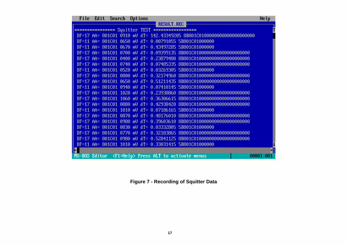
FIGURE 7 - RECORDING OF SQUITTER DATA...................................................................... 17
FIGURE 8 - PHOTO .................................................................................................................. 18
FIGURE 9 - PHOTO .................................................................................................................. 19

Mode-S Specific Services and Data Link Test Bench 1
1. INTRODUCTION
More and more aircraft will be fitted with Mode S data link equipment in the comingyears.
In the context of the Eurocontrol IIMSES programme, Eurocontrol is paying for theequipage of several aircraft with Mode S Specific Services capabilities. This will enablethe enhanced surveillance capability of the POEMS radars to be validated during thepre-operational phase, and at a later stage enable ATN type messages to beexchanged.
As no Test Bench is available on the market at the present time, a small portable TestBench has been developed at the EEC in order to test the Mode S installation of theseaircraft. The installations conform as far as is possible to the “Mode S Specific ServicesManual” issued by SICASP (June 97) and eventually to be included in the ICAO Annex10.
This technical note describes the Test Bench hardware and application software.
This test bench has already been used to verify a Mode S Specific Services installationon the Airbus Inter Transport A300/600ST aircraft (a.k.a. Beluga) at Toulouse airport.

Mode-S Specific Services and Data Link Test Bench 2
2. HARDWARE
A low powered Ground Station developed by Dassault Electronique is used to generateand receive Mode S interrogations and replies.
A PC driven Input/Output card also developed by Dassault enables a standard PC tocommunicate with and control the Mode S Ground Station.An omni-directional or simple directionally fixed antenna is used at the RF output of theTest Bench.
The Test Bench has a range of about 70 Km with this type of antenna.

Mode-S Specific Services and Data Link Test Bench 3
3. SOFTWARE
The application software package for the Test Bench has been developed by EEC.
The application is written in C and runs under the control of a real time multi-taskingsystem already used by us before for several other real time applications on Pcs.
The real time operating system is from On-Time Gmbh. Germany and is called RTKernel.
A library of functions was provided by Dassault [2] to enable control of their PC card.These functions have been updated and extended by Eurocontrol.
3.1. Functions performed by Test Bench Software
3.1.1. Listen for Mode S acquisition squitters
Extract Mode S addressExtract transponder capability
3.1.2. Listen for Mode S extended squitters
Receive Position squittersAirborne position reportsGround position reports
Receive Air Vector SquittersReceive Identification squitters
3.1.3. Send all call requests and decode replies UF11/DF11
3.1.4. Send surveillance request and receive replies UF 4/5 DF 4/5
3.1.5. Send Comm A message/requests and receive Comm B replies UF 20/21 DF 20/21
3.1.6. Send Comm C messages up to 16 segments UF 24
3.1.7. Receive Comm D messages up to 16 segments DF 24
3.1.8. Extract all GICB messages - BDS 05 to BDS FF
Display where relevant the aircraft parameters in engineering units

Mode-S Specific Services and Data Link Test Bench 4
3.1.9. Extract transponder Capability Report - BDS 10
3.1.10. Extract Aircraft Identification Report - BDS 20
3.1.11. Extract TCAS Report - BDS 30
3.1.12. Listen for and extract any Broadcast Messages emanating from Aircraft
Change of Capability ReportChange of Aircraft Identity ReportAir Initiated Comm B message availableComm D message available

Mode-S Specific Services and Data Link Test Bench 5
4. OPERATIONAL DETAILS
The software package produced by Eurocontrol is an executable programme which runsas a stand alone application on a standard IBM compatible PC.
This executable programme can be distributed freely, if further development isenvisaged by a user it would be necessary to purchase a licence from On Time Gmbh.for the RT Kernel system [4].
4.1. Application Details
The main menu of the application allows you to perform the following functions. Duringthe tests all data sent and received by the bench is recorded on the hard disk.
4.1.1. UF 11/DF 11
This function transmits All Call interrogations (UF 11) and listens for the aircraft replies(DF 11). When the Mode S address is acquired, the aircraft is then interrogated at alow rate with DF 4, 5, 20 and 21 interrogations (Rate is about 1/2 Hz). The Mode A codeand barometric altitude provided by the Mode S replies are then displayed on the PCscreen.
4.1.2. GICB
All GICB registers can be extracted and displayed on the PC screen. There is asecondary menu which enables the operator to choose one or more GICB registers or agroup of GICB registers to be extracted consecutively by the bench. The contents ofcertain GICB registers are displayed in engineering units when they have been specifiedby the Mode S Specific Services Manual [1] or by previous Eurocontrol documents [5].As well as the aircraft data GICBs the GICBs 10, 20, 30 are displayed (Capability report,Flight Identity and TCAS status).
4.1.3. CommA
CommA data link messages are sent to the aircraft. A second menu lets you choosefrom an uplink message list or send a free text message. At the present time themessage list contains messages formatted for the “old” data link protocol used byEurocontrol. Mode S Specific Service messages (or ATN message types) could beadded at a later stage. These messages are sent to the ADLP by the transponder andhave to be validated on the aircraft side.
4.1.4. CommB
This function listens during the surveillance phase to detect if the DR (Data Request)field of the Mode S reply has changed, indicating a downlink message has beenannounced by the aircraft and is waiting to be extracted by the ground. The DR field

Mode-S Specific Services and Data Link Test Bench 6
may be 0, 1, 2, 4, or 5 depending on the type of message being downlinked. DR=0means no message waiting, DR=1 means an AICB message is waiting, DR=2 means aTCAS state message is waiting, and DR 4 or 5 means a Broadcast message is waiting.The messages are extracted and displayed on the PC screen, decoding is done whenpossible. CommB closeout messages are sent after successful extraction of the AICBs.Broadcast messages time themselves out after 18 seconds. DR > 16 and < 32 arepossible but indicate CommD messages waiting and are dealt with later on.
4.1.5. Address Mode S
This function is simply to choose a Mode S address from the address list if severalaircraft are within range and it is required to test only one particular aircraft.
4.1.6. CommC
CommC (U-ELMs) are sent uplink to the aircraft. Up to 16 segments may be sent, themessage sent and the acknowledgement from the aircraft are displayed on the screen.If retries are required for some segments the number of retries and the segments resentare indicated.
4.1.7. CommD
CommD (D-ELMs) are extracted from the aircraft transponder and displayed on the PCscreen. Up to 16 downlink segments may be received in one burst.
The DR field is checked during surveillance replies, a DR field between 16 and 31indicates a CommD message is waiting to be extracted and the DR value indicates thenumber of segments to be extracted (Number of segments announced = DR - 15). Aclose out is sent by the bench after each CommD successfully extracted.
4.1.8. Squitter
This function simply listens to aircraft squitters and displays them on the PC screen.The Mode S addresses are decoded showing which country the aircraft is fromaccording to the ICAO Annex 10 list, and if possible the aircraft registration (France,USA) otherwise the Mode S address is shown in hexadecimal code (6 digits - 24 bits).
4.1.9. Stop Display
This function simply toggles the screen updating, it is sometimes useful to hold thescreen display steady whilst checking some parameters or values. The bench continuesto function normally during this time and the screen can be restarted by selecting stopdisplay a second time (toggle).
4.1.10. ADS-B

Mode-S Specific Services and Data Link Test Bench 7
The bench listens for acquisition and extended squitters from aircraft. The number ofboth types of squitter is counted, in order to verify the squitter rates. Extended squitterposition reports are decoded from the CPR data and the aircraft’s position is shown inlatitude and longitude, the altitude is also decoded. The identification squitter is alsodecoded and the aircraft’s flight identification is displayed.
Implementation of all the new extended squitter types will be added at a later stagewhen they have been finalised.

Mode-S Specific Services and Data Link Test Bench 8
5. COSTS
In order to give the reader an idea of the costs involved to develop his own test toolshere are the prices of the main components required.
• Mode S Station + PC I/O card 340 K FRF• Simple omnidirectional antenna 10 K FRF• Standard IBM compatible PC 10 K FRF• Real Time Kernel (RTK C 4.5) 1,5 K DEM• or Real Time Kernel (RTK C (32 bit)) 4 K DEM

Mode-S Specific Services and Data Link Test Bench 9
6. CONCLUSION
This test bench has already proved to be a very useful tool when validating Mode Sdata link installations. We intend to develop other Mode S tools using the test bench.

Mode-S Specific Services and Data Link Test Bench 10
G L O S S A R Y
CPR Compact Position Report [1]
GICB Ground Initiated CommB message
AICB Air Initiated CommB message
BDS CommB Definition Subfield
CommA Short data link uplink message (56 bits)
CommB Short data link downlink message (56 bits)
CommC Long data link uplink message (112 bits)
CommD Long data link downlink message (112 bits)
IIMSES Initial Implementation of Mode S in Europe
POEMS PreOperational European Mode S Stations
ELM Extended Length Message
U-ELM Uplink ELM (a.k.a. Comm C)
D-ELM Downlink ELM (a.k.a. Comm D)
R E F E R E N C E S
[1] - Mode S Specific Services Manual - ICAO Doc 9688-AN/952 June 97
[2] - Mode S Data-Link Ground Station - IRIS Software user’s Manual -Dassault Electronique 1408-903-000 Issue 3
[3] - Mode S Data-Link Ground Station - Supply Description ManualDassault Electronique 1408-902-000 Issue 3
[4] - RTKernel C 4.5 - User’s manual - On Time Gmbh Hamburg
[5] - DLPU Model C2 Aircraft Installation & BDS AllocationEEC Note 25/95 by P.Hunt

11
Figure 1 - Initial Menu

12
Figure 2 - Squitter reception

13
Figure 3 - Altitude and Mode A Code Reception

14
Figure 4 - Comm C Transmission

15
Figure 5 - ADS B Reception and CPR Decoding

16
Figure 6 - Result Recording of GICB Contents and Decoding in Engineering Units
17
Figure 7 - Recording of Squitter Data


A P P E N D I X
CONTENTS
This Appendix shows details of all the GICB registers at present decoded by the test bench.Other registers may be added when they become available.
Eurocontrol FormatBDS 1.0 - Capability ReportBDS 1.7 - Engine No. 1 ReportBDS 2.0 - Flight IdentityBDS 2.1 - Aircraft Referenced State Vector ReportBDS 2.4 - Weight and Balance ReportBDS 2.7 - Engine No. 2 ReportBDS 2.A - Radio System Frequency Report VHFBDS 3.1 - Waypoint InformationBDS 3.7 - Engine No. 3 ReportBDS 4.0 - Path and Attitude ReportBDS 4.1 - Waypoint IdentifierBDS 4.7 - Engine No. 4 ReportBDS 5.0 - Speed and Track ReportBDS 5.1 - Position ReportBDS 6.0 - Ground Referenced State VectorBDS 6.1 - G.M.T. ReportBDS 7.0 - Aircraft Intention 1 ReportBDS 7.1 - Meteorological ReportBDS 8.0 - Aircraft Intention 2 ReportBDS 9.0 - Aircraft Intention 3 ReportBDS A.0 - Deviation ReportBDS B.0 - Airspeeds ReportBDS C.0 - Altitude ReportBDS D.0 - Intention Report 1BDS D.1 - Turn Indication Report 1BDS D.2 - Turn Indication Report 2Mode S Specific Services FormatBDS 0.5 - Extended Squitter Airborne PositionBDS 0.6 - Extended Squitter Surface PositionBDS 0.7 - Extended Squitter StatusBDS 1.0 - Data Link Capability ReportBDS 2.0 - Aircraft IdentityBDS 4.0 - Aircraft IntentionBDS 4.3 - Aircraft IntentionBDS 4.4 - Meteorological Routine ReportBDS 4.5 - Meteorological Hazard ReportBDS 5.0 - Track and Turn ReportBDS 5.1 - Position Report CoarseBDS 5.2 - Position Report FineBDS 5.3 - Air-referenced State VectorBDS 6.0 - Heading and Speed Report
Page No.
123456789
1011121314151617181920212223242526
2728293031323334353637383940

Mode-S Specific Services and Data Link Test Bench EUROCONTROL
1
BDS 1,0 Capability Report
Eurocontrol Format
Purpose: To provide the DLPU status.
Notes:
1) Bite test bit B definition1 = Bite test successful.0 = Bite test failure.
2) DLPU status LED bit definition1 = LED on.0 = LED off
3) BDS 20 output1 = active0 = not active
4) ADI channels active bits c1 to c10. ( 10 channels )1 = channel active.
5) DLT ( cockpit Data Link Terminal ) bit d definition1 = DLT present and on-line
6) MICP ( cockpit printer ) bit m definition1 = printer present and on-line
7) GPFT ( General Purpose File Transfer ) g bit definition1 = GPFT initialised and available0 = GPFT not initialised.
8) Control unit bit u definition1 = control unit connected
9) Aircraft type field tttt definition
Indicates type of aircaft field 0 to 15 which is hard wiredon aircraft. This enables DLPU to process data from 15different types of aircraft installations.
10) SAL Sytem Address Label field ssssssss definition.
The SAL can be hard wired on the aircraft. Value from 00to FF hexadecimal. This is used by the file transfer facility.
BDSbit no.
Databit no.
Description Bit.
1 02 03 04 BDS 1,0 15 06 07 08 09 x10 x11 ( Not used ) x12 x13 x14 Bite test B15 Status LED S16 BDS 20 o/p T17 c 118 c 219 c 320 c 421 ADI c 522 Channels c 623 Active c 724 c 825 c 926 c 1027 DLT d28 MICP m29 GPFT g30 x31 x32 Not used x33 x34 x35 x36 Control unit u37 msb t38 Aircraft type t39 t40 lsb t41 msb s42 s43 s44 System s45 Address s46 Label s47 s48 lsb s49 x50 x51 x52 Not used x53 x54 x55 x56 x

Mode-S Specific Services and Data Link Test Bench EUROCONTROL
2
BDS 1, 7 Engine No. 1 Report
Eurocontrol Format
Status bit = 0 also if data too old.
BDSbit no.
Databit no.
Description ARINCbit no.
1 Status 1 = valid data 30&3123 msb = 128 % 284 275 266 257 N1 ACTUAL 248 Label 346 239 2210 Range = [0,256 %] 2111 2012 1913 lsb = 128/1024 % 1814 Status 1 = Valid data 30&311516 msb = 16384 lb/hr 2817 2718 2619 FUEL FLOW 2520 Label 347 2421 Range = 0, 32768 lb/hr 2322 2223 2124 2025 1926 1827 lsb = 8 lb/hr 1728 Status 1 = Valid data 30&3129 Sign 1 = -ve 2930 msb = 256 C 2831 2732 TOTAL AIR 2633 TEMPERATURE 2534 Label 211 2435 2336 Range = +-512 deg C 2237 2138 2039 msb = 0.5 C 1940 Status 1 = Valid data 30&3141 Sign 1 = -ve 2942 msb = 256 C 2843 2744 2645 STATIC AIR 2546 TEMPERATURE 2447 Label 213 2348 2249 Range = +- 512 C 2150 2051 lsb = 0.5 C 195253545556

Mode-S Specific Services and Data Link Test Bench EUROCONTROL
3
BDS 2,0 Flight Identity
Eurocontrol Format
Purpose: To report aircraft identification to the ground inaccordance with Annex.10 Volume IV, section 3.1.2.9
Notes:
1) Annex 10, Volume IV, section 3.1.2.9 provides a fulldefinition of BDS 2,0
2) The character coding to be used is identical to tahtdefined in Table 3-6 of Chapter 3, Annex 10, Volume IV.
3) This data may be input to ther transponder from sourcesother than the Mode S ADLP.
4) This format is used by the extended squitter application.
BDSbit no.
Data Description Bit
1 02 03 14 BDS 05 Label 2,0 06 07 08 091011 Character 1 see Note 2121314151617 Character 2 see Note 2181920212223 Character 3 see Note 2242526272829 Character 4 see Note 2303132333435 Character 5 see Note 2363738394041 Character 6 see Note 2424344454647 Character 7 see Note 2484950515253 Character 8 see Note 2545556

Mode-S Specific Services and Data Link Test Bench EUROCONTROL
4
BDS 2,1 Aircraft Referenced State Vector Report
Eurocontrol Format
Status bit = 0 also if data too old.
BDSbit no.
Databit no.
Description ARINCbit no.
1 Status 1 = valid data 30&312 Sign 293 284 275 MAGNETIC 266 HEADING 257 248 Label 320 239 2210 Range = [+-180 deg] 2111 2012 lsb = 0.18 deg 1913 Status 30&311415 2816 2717 TRUE AIR SPEED 2618 2519 Label 210 2420 2321 Range = [0,2048 kt] 2222 2123 2024 1925 1826 lsb = 0.5 kt] 1727 Status 30&3128 Sign 2929 ALTITUDE RATE 2730 2631 Label 212 or 365 2532 2433 Range =[+-16384 ft/min] 2334 2235 2136 lsb = 64 ft/min 2037 Status 30&3138 Sign 2939 2840 STATIC AIR 2741 TEMPERATURE 2642 2543 Label 213 2444 2345 Range = [+-512 °C] 2246 2147 2048 lsb = 0.5 °C 19
49 Status 30&3150 Sign 2951 NORMAL BODY 2652 ACCELERATION 2553 Label 333 2454 Range = [+-1g] 2355 2256 lsb = 0.16g 21

Mode-S Specific Services and Data Link Test Bench EUROCONTROL
5
BDS 2,4 Weight and Balance Report
Eurocontrol Format
Status bit = 0 also if data too old.
BDSbit no.
Databit no.
Description ARINCbit no.
1 Status 1 = valid data 30&3123 274 265 256 247 238 229 CENTRE OF GRAVITY 2110 Label 066 ( BCD ) 2011 Range = 0, 99.9 % 1912 1813 1714 1615 1516 Status 1 = valid data 30&311718 msb = 65536 lbs 2819 2720 2621 GROSS WEIGHT 2522 Label 075 2423 2324 Range = 0, 131072 lbs 2225 2126 2027 1928 1829 1730 msb = 16 lbs 163132333435363738394041424344454647484950515253545556

Mode-S Specific Services and Data Link Test Bench EUROCONTROL
6
BDS 2, 7 Engine No. 2 Report
Eurocontrol Format
Status bit = 0 also if data too old.
BDSbit no.
Databit no.
Description ARINCbit no.
1 Status 1 = valid data 30&3123 msb = 128 % 284 275 266 257 N1 ACTUAL 248 Label 346 239 2210 Range = [0,256 %] 2111 2012 1913 lsb = 128/1024 % 1814 Status 1 = Valid data 30&311516 msb = 16384 lb/hr 2817 2718 2619 FUEL FLOW 2520 Label 347 2421 Range = 0, 32768 lb/hr 2322 2223 2124 2025 1926 1827 lsb = 8 lb/hr 1728 Status 1 = Valid data 30&3129 Sign 1 = -ve 2930 msb = 256 C 2831 2732 TOTAL AIR 2633 TEMPERATURE 2534 Label 211 2435 2336 Range = +-512 deg C 2237 2138 2039 msb = 0.5 C 1940 Status 1 = Valid data 30&3141 Sign 1 = -ve 2942 msb = 256 C 2843 2744 2645 STATIC AIR 2546 TEMPERATURE 2447 Label 213 2348 2249 Range = +- 512 C 2150 2051 lsb = 0.5 C 195253545556

Mode-S Specific Services and Data Link Test Bench EUROCONTROL
7
BDS 2,A Radio System Frequency Report VHF
Eurocontrol Format
Status bit = 0 also if data too old.
BDSbit no.
Databit no.
Description ARINCbit no.
1 Status 1 = valid data 30&312 283 10 Mhz 274 265 256 247 1 Mhz 238 229 VHF COM 1 2110 Label 030 ( BCD ) 2011 0.1 Mhz 1912 1813 1714 1615 0.01 Mhz 1516 Status 1 = valid data 30&3117 2818 10 Mhz 2719 2620 2521 2422 1 Mhz 2323 2224 VHF COM 2 2125 Label 030 ( BCD ) 2026 0.1 Mhz 1927 1828 1729 1630 0.01 Mhz 153132333435363738394041424344454647484950515253545556

Mode-S Specific Services and Data Link Test Bench EUROCONTROL
8
BDS 3,1 Waypoint Information
Eurocontrol Format
Status bit = 0 also if data too old.
BDSbit no.
Databit no.
Description ARINCbit no.
1 Status 1 = valid data 30&312 Sign 293 284 BEARING TO WAYPOINT 275 266 Label 115 257 248 Range =[ +-180 deg ] 239 2210 2111 2012 lsb = 0.18 deg ] 1913 Status 30&3114 2915 2816 TIME TO GO 2717 2618 Label 002 2519 BCD 2420 2321 Range = [0,399.9 min] 2222 2123 2024 1925 1826 1727 1628 1529 Status3031 2932 2833 DISTANCE TO GO 2734 BCD 2635 Label 001 2536 2437 2338 2239 Range = [0,3999.9 nm] 2140 2041 1942 1843 1744 1645 1546 1447 1348 1249 1150515253 SPARE545556

Mode-S Specific Services and Data Link Test Bench EUROCONTROL
9
BDS 3, 7 Engine No. 3 Report
Eurocontrol Format
Status bit = 0 also if data too old.
BDSbit no.
Databit no.
Description ARINCbit no.
1 Status 1 = valid data 30&3123 msb = 128 % 284 275 266 257 N1 ACTUAL 248 Label 346 239 2210 Range = [0,256 %] 2111 2012 1913 lsb = 128/1024 % 1814 Status 1 = Valid data 30&311516 msb = 16384 lb/hr 2817 2718 2619 FUEL FLOW 2520 Label 347 2421 Range = 0, 32768 lb/hr 2322 2223 2124 2025 1926 1827 lsb = 8 lb/hr 1728 Status 1 = Valid data 30&3129 Sign 1 = -ve 2930 msb = 256 C 2831 2732 TOTAL AIR 2633 TEMPERATURE 2534 Label 211 2435 2336 Range = +-512 deg C 2237 2138 2039 msb = 0.5 C 1940 Status 1 = Valid data 30&3141 Sign 1 = -ve 2942 msb = 256 C 2843 2744 2645 STATIC AIR 2546 TEMPERATURE 2447 Label 213 2348 2249 Range = +- 512 C 2150 2051 lsb = 0.5 C 195253545556

Mode-S Specific Services and Data Link Test Bench EUROCONTROL
10
BDS 4,0 Path & Attitude Report
Eurocontrol Format
Status bit = 0 also if data too old.
BDSbit
Databit
Description ARINCbit1 Status 1 = valid data 30&31
2 Sign 293 msb=90 deg 284 275 266 FLIGHT PATH ANGLE 257 Label 322 248 239 Range = [+-180 deg ] 2210 2111 2012 lsb=0.18 deg 19
13 Status 1 = valid data 30&3114 Sign 2915 msb = 2g 2816 2717 2618 FLIGHT PATH ACCEL. 2519 Label 323 2420 2321 Range = [+-4g ] 2222 2123 2024 1925 1826 lsb=0.001g 17
27 Status 1 = valid data 30&3128 Sign 2929 msb=90 deg 2830 2731 2632 2533 CORRECTED ANGLE 2434 OF ATTACK 2335 Label 241 2236 2137 Range = [+- 180 ] 2038 1939 1840 lsb=0.044 deg 17
41 Status 1 = valid data 30&3142 Sign 2943 msb=65,536 ft 2844 2745 2646 2547 BARO. CORRECTED 2448 ALTITUDE 2349 Label 204 2250 2151 Range [ 0,131072 ft] 2052 1953 1854 1755 1656 lsb = 8 ft 15

Mode-S Specific Services and Data Link Test Bench EUROCONTROL
11
BDS 4,1 Waypoint Identifier
Eurocontrol Format
Status bit = 0 also if data too old.
BDSbit no.
Databit no.
Description ARINCbit no.
1 Status 1 = valid data 30&312 293 284 275 266 257 248 char 3 239 2210 2111 ACTIVE WAYPOINT 1 2012 Label 356 1913 ISO 5 Characters 1814 1715 char 2 1616 1517 1418 1319 1220 1121 1022 char 1 923 Status 1 = valid data 30&3124 2925 2826 2727 2628 2529 2430 char 6 2331 2232 2133 ACTIVE WAYPOINT 2 2034 Label 357 1935 ISO 5 Characters 1836 1737 char 5 1638 1539 1440 1341 1242 1143 1044 char4 945 Status 1 = valid 30&3146 Sign 1 = west 2947 msb = 90 deg 2848 2749 2650 DESIRED TRACK 2551 Label 114 2452 Range = +- 180 deg 2353 2254 2155 2056 lsb = 90/512 deg 19

Mode-S Specific Services and Data Link Test Bench EUROCONTROL
12
BDS 4, 7 Engine No. 4 Report
Eurocontrol Format
Status bit = 0 also if data too old.
BDSbit no.
Databit no.
Description ARINCbit no.
1 Status 1 = valid data 30&3123 msb = 128 % 284 275 266 257 N1 ACTUAL 248 Label 346 239 2210 Range = [0,256 %] 2111 2012 1913 lsb = 128/1024 % 1814 Status 1 = Valid data 30&311516 msb = 16384 lb/hr 2817 2718 2619 FUEL FLOW 2520 Label 347 2421 Range = 0, 32768 lb/hr 2322 2223 2124 2025 1926 1827 lsb = 8 lb/hr 1728 Status 1 = Valid data 30&3129 Sign 1 = -ve 2930 msb = 256 C 2831 2732 TOTAL AIR 2633 TEMPERATURE 2534 Label 211 2435 2336 Range = +-512 deg C 2237 2138 2039 msb = 0.5 C 1940 Status 1 = Valid data 30&3141 Sign 1 = -ve 2942 msb = 256 C 2843 2744 2645 STATIC AIR 2546 TEMPERATURE 2447 Label 213 2348 2249 Range = +- 512 C 2150 2051 lsb = 0.5 C 195253545556

Mode-S Specific Services and Data Link Test Bench EUROCONTROL
13
BDS 5,0 Speed & Track Report
Eurocontrol Format
Status bit = 0 also if data too old.
BDS Data Description ARINC1 Status 1 = valid data 30&3123 msb = 2.048 284 275 266 257 MACH NUMBER 248 Label 205 239 2210 Range = [ 0, 4.096 ] 2111 2012 1913 1814 lsb = 2.048/2048 = 0.001 1715 Status 1 = valid data 30&311617 msb = 512 kt 2818 2719 2620 COMPUTED AIR 2521 Label 206 2422 2323 Range = [ 0, 1023.5 ] 2224 2125 2026 1927 lsb = 0.5 kt 1828 Status 1 = valid data 30&3129 Sign 1 = westward 2930 msb = 90 deg. 2831 2732 2633 2534 TRACK ANGLE TRUE 2435 Label 313 2336 2237 Range = [ -180,+180 ] 2138 2039 1940 1841 lsb = 0.044 deg 1742 Status 1 = valid data 30&3143 Sign 1 = westward 2944 msb = 90 deg 2845 2746 2647 2548 TRACK ANGLE 2449 MAGNETIC 2350 Label 317 2251 2152 Range = [ -180,+180 ] 2053 1954 1855 lsb = 0.044 deg 1756

Mode-S Specific Services and Data Link Test Bench EUROCONTROL
14
BDS 5,1 Position Report
Eurocontrol Format
Status bit = 0 also if data too old.
BDSbit no.
Databit no.
Description ARINCbit no.
1 Status 1 = valid data 30&312 Sign 293 msb = 90 deg 284 275 266 257 248 239 LATITUDE 2210 Label 310 2111 2012 Range =[ +-180 deg ] 1913 1814 1715 1616 1517 1418 1319 1220 lsb = 90/131072 deg 1121 Status 1 = valid data 30&3122 Sign 2923 msb = 90 deg 2824 2725 2626 2527 2428 2329 LONGITUDE 2230 Label 311 2131 2032 Range =[ +-180 deg ] 1933 1834 1735 1636 1537 1438 1339 1240 lsb = 90/131072 deg 1141 Status 1 = valid data 30&3142 Sign 2943 msb = 65536 ft 2844 2745 2646 ALTITUDE 2547 Label 203 2448 2349 Range = -1000,131072 ft 2250 2151 2052 1953 1854 1755 1656 lsb = 8 ft 15

Mode-S Specific Services and Data Link Test Bench EUROCONTROL
15
BDS 6,0 Ground Referenced State Vector
Eurocontrol Format
Status bit = 0 also if data too old.
BDSbit
Databit
Description ARINCbit1 Status 1 = valid data 30&31
2 Sign 1 = westward 293 msb=90 deg 284 275 266 TRACK ANGLE 257 MAGNETIC 248 Label 317 239 2210 Range = [ -180, +180 ] 2111 2012 lsb=0.18 deg 19
13 Status 1 = valid data 30&311415 msb=1024 kt 2716 2617 2518 2419 GROUND SPEED 2320 Label 312 2221 2122 Range = [ 0, 2048 kt ] 2023 1924 1825 1726 lsb=0.5 kt 16
27 Status 1 = valid data 30&3128 Sign 2929 msb=8192 ft/min 2730 2631 ALTITUDE RATE 2532 Label 212 or 365 2433 Range = [ +-16384 ft/m] 2334 2235 2136 lsb=64 ft/min 20
37 Status 1 = valid data 30&3138 Sign 2939 msb=256 deg 2840 2741 2642 STATIC AIR TEMP. 2543 Label 213 2444 Range = [ +-512 deg ] 2345 2246 2147 2048 lsb=0.5 deg 19
49 Status 1 = valid data 30&3150 Sign 2951 msb=0.5g 2652 BODY NORMAL 2553 ACCELERATION 2454 Label 333 2355 Range = [ +-1g] 2256 msb=0.016g 21

Mode-S Specific Services and Data Link Test Bench EUROCONTROL
16
BDS 6,1 G.M.T. Report
Eurocontrol Format
Status bit = 0 also if data too old.
BDSbit no.
Databit no.
Description ARINCbit no.
1 Status 1 = valid data 30&3123 284 275 Hrs 0 -23 266 257 248 239 2210 GMT Binary Word 2111 Label 150 2012 Minutes 0 - 59 1913 1814 1715 1616 1517 1418 Seconds 0 - 59 1319 1220 Status 1 = valid data 30&3121 2922 2823 2724 2625 2526 FLIGHT NUMBER (BCD) 2427 Label 261 2328 2229 2130 2031 1932 1833 1734 1635 1536 1437 Status 1 = valid data 30&3138 2939 2840 2741 2642 2543 GMT BCD Word 2444 Label 125 2345 2246 2147 2048 1949 1850 1751 1652 1553 1454 1355 1256 11

Mode-S Specific Services and Data Link Test Bench EUROCONTROL
17
BDS 7,0 Aircraft Intention 1 Report
Eurocontrol Format
Status bit = 0 also if data too old.
BDSbit no.
Databit no.
Description ARINCbit no.
1 Status 1 = valid data 30&3123 284 275 SELECTED ALTITUDE 266 Label 102 257 248 Range = [0,65536 ft] 239 2210 2111 2012 1913 1814 lsb = 16 ft 1715 Status 1 = Valid data 30&3116 Sign 2917 2818 SELECTED HEADING 2719 Label 101 2620 Range = [+-180 deg] 2521 2422 2323 2224 lsb = 0.8 deg 2125 Status 30&3126 2527 2428 2329 STATUS WORD 1 2230 Label 270 2131 2032 Discrete data 1933 1834 1735 1636 1537 1438 1339 1240 1141 Status 30&3142 2743 2644 2545 STATUS WORD 2 2446 Label 271 2347 2248 Discrete data 2149 2050 1951 1852 1753 1654 1555 1456 13

Mode-S Specific Services and Data Link Test Bench EUROCONTROL
18
BDS 7,1 Meteorological Report
Eurocontrol Format
Status bit = 0 also if data too old.
BDSbit no.
Databit no.
Description ARINCbit no.
1 Status 1 = valid data 30&312 Sign 1 = left wing down 293 msb = 45 deg 274 265 ROLL ANGLE 256 Label 325 247 238 Range =[ +-90 deg ] 229 2110 lsb = 45/128 deg 2011 Status 1 = valid data 30&3112 Sign 1 = down 2913 msb = 4096 ft/min 2614 ALTITUDE RATE or 2515 INERTIAL VERTICAL VEL. 2416 Label 212 or 365 2317 Range +-8192 ft/min 2218 lsb = 128 ft/min 2119 Status 1 = valid data 30&3120 2921 msb = 128 kt 2822 2723 WIND SPEED 2624 Label 315 2525 2426 Range = 0,256 kt 2327 2228 lsb = 1 kt 2129 Status 1 = valid data 30&3130 Sign 1 = west 2931 msb = 90 deg 2832 2733 WIND ANGLE 2634 Label 316 2535 2436 Range = +-180 deg 2337 2238 lsb = 90/1218 deg 2139 Status 1 = valid data 30&3140 Sign 1 = -ve 2941 msb = 256 C 2842 STATIC AIR 2743 TEMPERATURE 2644 Label 213 2545 2446 Range +- 512 deg C 2347 2248 2149 2050 lsb = 0.5 C 1951 Status 1 = valid data 30&3152 Sign 1 = -ve 2953 msb = 0.5 g 2654 ACCELERATION 2555 Label 333 2456 lsb = 1/16 g 23

Mode-S Specific Services and Data Link Test Bench EUROCONTROL
19
BDS 8,0 Aircraft Intention 2 Report
Eurocontrol Format
Status bit = 0 also if data too old.
BDSbit no.
Databit no.
Description ARINCbit no.
1 Status 1 = valid data 30&3123 msb = 256 kt 284 275 SELECTED AIR SPEED 266 Label 103 257 248 Range = [0,512 kt] 239 2210 2111 2012 1913 lsb = 0.25 kt 1814 Status 1 = Valid data 30&3115 Sign 1 = down 2916 msb = 8192 2817 2718 SELECTED ALTITUDE 2619 RATE 2520 Label 104 2421 Range = [+-16384 ft/min] 2322 2223 2124 2025 lsb = 16 ft/min 1926 Status 30&312728 msb = 32768 ft 2829 2730 2631 SELECTED ALTITUDE 2532 Label 102 2433 2334 Range = 0, 65536 ft 2235 2136 2037 1938 1839 msb = 16 ft 1740 Status 30 & 314142 2543 2444 2345 STATUS WORD 1 2246 Label 270 2047 1548 Discrete data 1449 135051 Status 30 & 3152 STATUS WORD 253 Label 271 2754 2255 Discrete data 2156 20

Mode-S Specific Services and Data Link Test Bench EUROCONTROL
20
BDS 9, 0 Aircraft Intention 3 Report
Eurocontrol Format
Status bit = 0 also if data too old.
BDSbit no.
Databit no.
Description ARINCbit no.
1 Status 1 = valid data 30&3123 msb = 2048 mM 284 275 SELECTED MACH 266 Label 106 257 248 Range = [0,4096 mM] 239 2210 2111 2012 1913 lsb = 2 mM 1814 Status 1 = Valid data 30&3115 Sign 1 = down 2916 msb = 8192 2817 2718 SELECTED ALTITUDE 2619 RATE 2520 Label 104 2421 Range = [+-16384 ft/min] 2322 2223 2124 2025 lsb = 16 ft/min 1926 Status 30&312728 msb = 32768 ft 2829 2730 2631 SELECTED ALTITUDE 2532 Label 102 2433 2334 Range = 0, 65536 ft 2235 2136 2037 1938 1839 msb = 16 ft 1740 Status 30 & 314142 2543 2444 2345 STATUS WORD 1 2246 Label 270 2047 1548 Discrete data 1449 135051 Status 30 & 3152 STATUS WORD 253 Label 271 2754 2255 Discrete data 2156 20

Mode-S Specific Services and Data Link Test Bench EUROCONTROL
21
BDS A,0 Deviation Report
Eurocontrol Format
Status bit = 0 also if data too old.
BDSbit no.
Databit no.
Description ARINCbit no.
1 Status 1 = valid data 30&312 Sign 293 msb = 64 nm 284 275 266 257 CROSS TRACK ERROR 248 Label 116 239 2210 Range =[ 0, 128 mn] ] 2111 2012 1913 1814 1715 1616 1517 lsb =0.004 nm 1418 Status 1 = valid data 30&3119 Sign 1 = low 2920 msb = 1024 ft 2821 2722 VERTICAL DEVIATION 2623 Label 117 2524 2425 Range = 0, 2048 ft 2326 2227 2128 2029 1930 lsb = 1 ft 1831 Status 1 = valid data 30&3132 Sign 1 = -ve 2933 msb = 0.5 g 2634 BODY NORMAL 2535 ACCELERATION 2436 Label 333 2337 Range = +- 1g 2238 lsb = 1/64 g 21394041424344454647484950515253545556

Mode-S Specific Services and Data Link Test Bench EUROCONTROL
22
BDS B,0 Airspeeds Report
Eurocontrol Format
Status bit = 0 also if data too old.
BDSbit no.
Databit no.
Description ARINCbit no.
1 Status 1 = valid data 30&3123 msb = 512 kt 284 275 COMPUTED AIR SPEED 266 Label 206 257 248 Range =[ 0, 1024 kt ] 239 2210 2111 2012 1913 1814 lsb = 0.25 kt 1715 Status 1 = valid data 30&311617 msb = 1024 kt 2818 2719 TRUE AIR SPEED 2620 Label 210 2521 2422 Range =[ 0, 2048 kt ] 2323 2224 2125 2026 1927 1828 lsb = 0.5 kt 1729 Status 1 = valid data 30&313031 msb = 2048 mM 2832 2733 MACH 2634 Label 205 2535 2436 Range =[ 0, 4.096 ] 2337 2238 2139 2040 1941 1842 1743 1644 lsb = 0.00025 1545 Status 1 = valid data 30&3146 Sign 1 = west 2947 msb = 90 deg 2848 2749 MAGNETIC HEADING 2650 Label 320 2551 2452 Range =[+-180 deg ] 2353 2254 2155 2056 lsb = 90/512 deg 19

Mode-S Specific Services and Data Link Test Bench EUROCONTROL
23
BDS C,0 Altitude Report
Eurocontrol Format
Status bit = 0 also if data too old.
BDSbit no.
Databit no.
Description ARINCbit no.
1 Status 1 = valid data 30&3123 msb = 4096 ft 284 275 266 257 RADIO HEIGHT 248 Label 164 239 2210 Range = 0, 8192 ft 2111 2012 1913 1814 1715 lsb = 1 ft 1616 Status 1 = valid data 30&311718 msb = 512 mb 2719 2620 AVERAGE STATIC 2521 PRESSURE 2422 Label 246 2323 2224 Range 0,1024 mb 2125 2026 1927 1828 1729 lsb = 0.25 mb 1630 Status 1 = valid data 30&313132 msb = 65536 ft 2833 2734 2635 2536 2437 2338 ALTITUDE 2239 Label 203 2140 2041 Range = 0, 131072 ft 1942 1843 1744 1645 1546 1447 1348 lsb = 1 ft 124950515253545556

Mode-S Specific Services and Data Link Test Bench EUROCONTROL
24
BDS D,0 Intention Report 1
Eurocontrol Format
Status bit = 0 also if data too old.
BDSbit
Databit
Description ARINCbit1 Status 1 = valid data 30&31
2 Sign 293 msb 90 deg 284 275 266 SELECTED COURSE 257 Label 100 248 Range [+-180 deg ] 239 2210 lsb 0.7 deg 21
11 Status 1 = valid data 30&3112 Sign 2913 msb 90 deg 2814 2715 SELECTED HEADING 2616 Label 101 2517 Range [+-180 deg ] 2418 2319 2220 lsb 0.7 deg 21
21 Status 1 = valid data 30&3122 Sign 2923 msb 32 768 ft 2824 2725 2626 SELECTED ALTITUDE 2527 Label 102 2428 Range [0,65 536 ft] 2329 2230 2131 2032 1933 1834 lsb 16 ft 17
35 Status 1 = valid data 30&3136 Sign 2937 msb 90 deg 2838 2739 DESIRED TRACK 2640 Label 114 2541 Range [+-180 deg ] 2442 2343 2244 lsb 0.7 deg 21
45 Status 1 = valid data 30&3146 Sign 2947 msb 16339 ft/min 2848 2749 INERTIAL VERTICAL 2650 VELOCITY 2551 Label 365 2452 Range [0,32678 ft/min] 2353 2254 2155 2056 lsb = 32 ft/min 19

Mode-S Specific Services and Data Link Test Bench EUROCONTROL
25
BDS D,1 Turn Indication Report 1
Eurocontrol Format
Status bit = 0 also if data too old.
BDSbit no.
Databit no.
Description ARINCbit no.
1 Status 1 = valid data 30&312 Sign 293 msb 22.5 deg 264 ROLL ANGLE 255 Label 325 246 Range [+- 45 deg ] 237 228 lsb 0.7 deg 21
9 Status 1 = valid data 30&3110 Sign 2911 msb 56 deg/sec 2812 2713 ROLL RATE 2614 Label 327 2515 Range [0,128 deg/sec] 2416 2317 lsb 1 deg/sec 22
18 Status 1 = valid data 30&3119 Sign 2920 msb 16 deg/sec 2821 2722 TRACK ANGLE RATE 2623 Label 335 2524 Range [ +- 32 deg/sec 2425 2326 lsb 0.25 deg/sec 22
27 Status 1 = valid data 30&3128 Sign 2929 msb 90 deg 2830 2731 2632 MAGNETIC HEADING 2533 Label 320 2434 Range [+-180 deg] 2335 2236 2137 2038 1939 1840 lsb 0.044 deg 17
41 Status 1 = valid data 30&3142 msb 0.25 g 2543 2444 CROSS TRACK ACCEL 2345 Label 363 2246 Range [0,0.5g] 2147 2048 lsb 0.004g 19
49 Status 1 = valid data 30&3150 msb 0.25 g 2551 2452 CROSS HEAD. ACCEL 2353 Label 376 2254 Range [0,0.5g] 2155 2056 lsb 0.004g 19

Mode-S Specific Services and Data Link Test Bench EUROCONTROL
26
BDS D,2 Turn Indication Report 2
Eurocontrol Format
Status bit = 0 also if data too old.
BDSbit
Databit
Description ARINCbit1 Status 1 = valid data 30&31
2 Sign 293 msb 22.5 deg 264 ROLL ANGLE 255 Label 325 246 Range [+- 45 deg ] 237 228 lsb 0.7 deg 21
9 30&3110 2911 msb 56 deg/sec 2812 2713 ROLL RATE 2614 Label 327 or 337 2515 Range [128 deg/sec] 2416 2317 lsb 1 deg/sec 22
18 Status 1 = valid data 30&3119 Sign 2920 2821 2722 TRACK ANGLE RATE 2623 Label 335 2524 Range [ 0,32 deg/sec] 2425 2326 22
27 Status 1 = valid data 30&3128 Sign 2929 msb 90 deg 2830 2731 2632 2533 TRACK ANGLE TRUE 2434 Label 313 2335 Range [+-180 deg] 2236 2137 2038 1939 1840 lsb 0.044 deg 17
41 Status 1 = valid data 30&3142 msb 0.25 g 2543 2444 CROSS TRACK ACCEL 2345 Label 363 2246 Range [0,0.5g] 2147 2048 lsb 0.004 g 19
49 Status 1 = valid data 30&3150 msb 0.25 g 2551 2452 CROSS HEAD. ACCEL 2353 Label 376 2254 Range [0,0.5g] 2155 2056 lsb 0.004 g 19

Mode-S Specific Services and Data Link Test Bench
EUROCONTROL
27
BDS 0,5 Extended Squitter Airborne Position
ModeS Specific Service Format
PURPOSE: To provide accurate airborne positioninformation.
TYPE coding :0 No position information1 Idenification (aircraft type set D)2 Idenification (aircraft type set C)3 Idenification (aircraft type set B)4 Idenification (aircraft type set A)5 Surface position µ ≤ 2m (0.001 nm)6 Surface position 2m < µ ≤ 18 m (0.01 nm)7 Surface position 18m < µ ≤ 185 m (0.1 nm)8 Surface position 185 m < µ9 Airborne position * µ ≤ 2m (0.001 nm)10 Airborne position * 2m < µ ≤ 18 m (0.01 nm)11 Airborne position * 18m < µ ≤ 185 m (0.1 nm)12 Airborne position * 185 m < µ ≤ 740m (0.4 nm)13 Airborne position * 740m < µ ≤ 1.85km (1 nm)14 Airborne position * 1.85km < µ ≤ 7.4km (4 nm)15 Airborne position * 7.4km < µ ≤ 18.5 km (10 nm)16 Airborne position * 18.5km < µ17 Airborne position # µ ≤ 18 m (0.01nm)18 Airborne position # 18 m < µ19 Airborne velocity information20-28 Unassigned29 Event-driven message C30 Event-driven message B31 Event-driven message A
* = 25/100 ft barometric altitude# = GNSS height ( TBD )µ = Horizontal position accuracy ( 95% containment value)
Surveillance Status:
0 No information1 Emergency conditions (ModeA codes 7700/7600/7500 )2 Special position Identifier (SPI)3 Change in SSR Mode A code
BDSbitno.
Description
123 TYPE456 SURVEILLANCE7 STATUS8 Reseved for ACAS91011 ALTITUDE12 specified by Type field1314 As specified in section15 3.1.2.6.5.4 of Annex 10 vol16 4 but with the M bit
removed17 or GNSS height18192021 Unassigned22 CPR Format/Time23 msb2425262728 ENCODED29 LATITUDE30313233343536373839 lsb40 msb4142434445 ENCODED46 LONGITUDE47484950515253545556 lsb
Mode-S Specific Services and Data Link Test Bench
EUROCONTROL
28
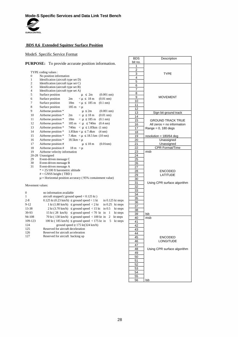
BDS 0,6 Extended Squitter Surface Position
ModeS Specific Service Format
PURPOSE: To provide accurate position information.
TYPE coding values :0 No position information1 Idenification (aircraft type set D)2 Idenification (aircraft type set C)3 Idenification (aircraft type set B)4 Idenification (aircraft type set A)5 Surface position µ ≤ 2m (0.001 nm)6 Surface position 2m < µ ≤ 18 m (0.01 nm)7 Surface position 18m < µ ≤ 185 m (0.1 nm)8 Surface position 185 m < µ9 Airborne position * µ ≤ 2m (0.001 nm)10 Airborne position * 2m < µ ≤ 18 m (0.01 nm)11 Airborne position * 18m < µ ≤ 185 m (0.1 nm)12 Airborne position * 185 m < µ ≤ 740m (0.4 nm)13 Airborne position * 740m < µ ≤ 1.85km (1 nm)14 Airborne position * 1.85km < µ ≤ 7.4km (4 nm)15 Airborne position * 7.4km < µ ≤ 18.5 km (10 nm)16 Airborne position * 18.5km < µ17 Airborne position # µ ≤ 18 m (0.01nm)18 Airborne position # 18 m < µ19 Airborne velocity information20-28 Unassigned29 Event-driven message C30 Event-driven message B31 Event-driven message A
* = 25/100 ft barometric altitude# = GNSS height ( TBD )µ = Horizontal position accuracy ( 95% containment value)
Movement values:
0 no information available1 aircraft stopped ( ground speed < 0.125 kt )2-8 0.125 kt (0.23 km/h) ≤ ground speed < 1 kt in 0.125 kt steps9-12 1 kt (1.80 km/h) ≤ ground speed < 2 kt in 0.25 kt steps13-38 2 kt (3.70 km/h) ≤ ground speed < 15 kt in 0.5 kt steps39-93 15 kt ( 28 km/h) ≤ ground speed < 70 kt in 1 kt steps94-108 70 kt ( 130 km/h) ≤ ground speed < 100 kt in 2 kt steps109-123 100 kt ( 185 km/h) ≤ ground speed < 175 kt in 5 kt steps124 ground speed ≥ 175 kt(324 km/h)125 Reserved for aircraft deceleration126 Reserved for aircraft acceleration127 Reserved for aircraft backing up
BDSbit no.
Description
123 TYPE456789 MOVEMENT10111213 Sign bit ground track1415 GROUND TRACK TRUE16 All zeros = no information17 Range = 0, 180 degs1819 resolution = 180/64 deg20 Unassigned21 Unassigned22 CPR Format/Time23 msb2425262728 ENCODED29 LATITUDE3031 Using CPR surface algorithm3233343536373839 lsb40 msb4142434445 ENCODED46 LONGITUDE4748 Using CPR surface algorithm4950515253545556 lsb

Mode-S Specific Services and Data Link Test Bench
EUROCONTROL
29
BDS 0,7 Extended Squitter Status
ModeS Specific Service Format
PURPOSE: To provide information on thecapability and status of the extended squitter rate ofthe transponder.
Transmission rate subfield coding:
0 = No capability to determine surface squitter rate.1 = High surface squitter rate selected.2 = Low surface squitter rate selected.3 = Unassigned
Altitude type subfield (ATS) coding :
0 = Barometric altitude.1 = GNSS height.
Note : Aircraft determination of surface squitter rate.
For aircraft that have the capability to automatically determine their surface squitter rate, the method that must be used to switch between high and low transmission rates is as follows :
a) Switching from high to low rate:
b) Switching from low to high rate:
I) the aircraft’s position has changed by 10 metres or more since the low rate was selected; or
ii) the aircraft’s ground speed exceeds one knot.
BDSbit no.
Description
1 TRANSMISSION RATE2 SUBFIELD (TRS)3 ATS Altitude type
subfield4567891011121314151617181920212223242526272829303132333435363738394041424344454647484950515253545556

Mode-S Specific Services and Data Link Test Bench
EUROCONTROL
30
BDS 1,0 Data Link Capability Report
ModeS Specific Service Format
Purpose: To report the data link capability of the ModeS transponder /data link installation, in accordance withsection 5.2.9 of the Mode S subnetwork SARPs ( seeparagraph 1.8 ).
Notes :
1) The Mode S subnetwork SARPs must be consulted forthe full definition of BDS 1,0.
2) Bit 25 is used as a status bit for all BDS buffers.
3) Starting from the Msb, each subsequent bit positionrepresents the DTE subaddresses in the range from 0 to15.
4) The enhanced protocol indicator denotes a Level 5transponder when set to 1 and a Level 2 to 4transponder when set to 0.
5) The squitter capability subfield (SCS) is interpretedas follows:0 = squitter registers are not updated1 = squitter registers are being updated.
6) The surveillance identifier (SI) bit is interpreted asfollows:0 = no surveillance identifier code capability1 = surveillance identifier code capability
7) Bit 36 is toggled to indicate that the common usageGICB capability report (BDS 17) has changed. To avoidthe generation of too many broadcast capability reportchanges, BDS 1,7 should be sampled at approximatelyone-minute intervals to check for changes.
BDSbit no.
Data Description Bit
1 02 03 04 BDS 15 Label 1,0 06 07 08 09 Continuation flag10111213141516 Reserved for ACAS171819 Mode S subnetwork20 version number21222324 Transponder enhanced protocol indicator Note 425 ModeS specific services capability
2627 Uplink ELM capability282930 Downlink ELM capability313233 Aircraft Identification capability
34 Squitter capability subfield(SCS) Note 535 Surveillance identifier Note 636 Common usage GICB capability report Note 73738 Reserved for ACAS394041 Msb4243444546 Bit array indicating the support47 status of DTE subaddresses48 0 to 154950515253545556 Lsb

Mode-S Specific Services and Data Link Test Bench
EUROCONTROL
31
BDS 2,0 Aircraft Identity
ModeS Specific Service Format
Purpose: To report aircraft identification to the ground inaccordance with Annex.10 Volume IV, section 3.1.2.9
Notes:
1) Annex 10, Volume IV, section 3.1.2.9 provides a fulldefinition of BDS 2,0
2) The character coding to be used is identical to tahtdefined in Table 3-6 of Chapter 3, Annex 10, Volume IV.
3) This data may be input to ther transponder fromsources other than the Mode S ADLP.
4) This format is used by the extended squitterapplication.
BDSbit no.
Data Description Bit
1 02 03 14 BDS 05 Label 2,0 06 07 08 091011 Character 1 see Note 2121314151617 Character 2 see Note 2181920212223 Character 3 see Note 2242526272829 Character 4 see Note 2303132333435 Character 5 see Note 2363738394041 Character 6 see Note 2424344454647 Character 7 see Note 2484950515253 Character 8 see Note 2545556

Mode-S Specific Services and Data Link Test Bench
EUROCONTROL
32
BDS 4,0 Aircraft intention
Purpose: To provide ready access to information aboutan aircraft’s short-term intentions, in order to improvethe effectiveness of conflict probes and to provideadditional tactical information to controllers.
Notes:
1) The data entered into this register should be derivedfrom the sources that are controlling the aircraft.
2) Selected course/heading and selected airspeed/machare switchable, with an extra switch bit to indicate whichparameter is in use. It is defined as follows:
SWITCH bit 0 1Course/heading Course HeadingAirspeed/Mach Airspeed Mach
BDSbit no.
Data Description ARINCbit no.
1 Status 1 = valid data 30&312 Sign msb = 32768 ft 283 274 SELECTED ALTITUDE 265 Label 102 256 247 238 Range =[ 0, 65520 ft ] 229 2110 2011 1912 1813 lsb = 16 ft 1714 1 = valid data 30&3115 Sign 1 = minus 2916 msb = 8192 ft/min 2717 2618 SELECTED ALTITUDE 2519 RATE 2420 Label 104 2321 2222 Range = [+- 16352 ft/min ] 2123 2024 lsb = 32 ft/min 1925 SWITCH26 STATUS 30&3127 SIGN 2928 msb = 90 deg 2829 2730 SELECTED MAGNETIC 2631 COURSE / HEADING 2532 Label 100 / 101 2433 Range = [+-180 deg] 2334 2235 lsb = 360/512 deg 2136 SWITCH37 STATUS 30&3138 msb = 256 kt/Mach 2048 2739 2640 SELECTED 2541 AIRSPEED/MACH 2442 Label 103 / 106 2343 2244 Range = [ 0,512 kt] 2145 or [0,4.096 Mach] 2046 1947 lsb = 0.5 kt/Mach 0.004 1848 STATUS of MODE Fields49 MODE50 SELECTED ALTITUDE51 MODE52 SELECTED ALTITUDE RATE53 MODE54 SELECT. COURSE/HEADING55 MODE56 SELECTED AIRSPEED/MACH

Mode-S Specific Services and Data Link Test Bench
EUROCONTROL
33
BDS 4,3 Aircraft intention
ModeS Specific Service Format
Purpose: To provide ready access to details about thenext waypoint on an aircraft’s route, without the need toestablish a data link dialogue with the flight managementsystem. This will assist with short and medium termtactical control.
Note:Time to go and Distance to go are Binary CodedDecimal values, where each decimal digit requires 4 bitsof data.
BDSbit no.
Data Description ARINCbit no.
1 Status 1 = valid data 30&312 Sign 293 Msb=90 deg. 284 275 266 BEARING TO WAYPOINT 257 Label 115 248 239 Range=[+-180 deg.] 2210 2111 2012 Lsb= 360/2048 degs. 1913 Status 1 = valid data 30&3114 2915 10 min. digit 2816 2717 2618 TIME TO GO 2519 Label 002 (BCD) 2420 1 min. 2321 Range=[0, 99.9 min] 2222 2123 0.1 min 2024 1925 1826 Status 1 = valid data 30&3127 2928 100 nm. digit 2829 2730 2631 DISTANCE TO GO 2532 10 nm. 2433 Label 001 (BCD) 2334 2235 Range=[0,999.9 nm] 2136 2037 1 nm. 1938 1839 1740 0.1 nm. 1641 1542 1443444546474849 UNASSIGNED50515253545556

Mode-S Specific Services and Data Link Test Bench
EUROCONTROL
34
BDS 4,4 Meteorological Routine Report
Purpose: To allow meteorological data to be collectedby ground systems.
The decimal value of the binary coded ( figure of merit )FOM/SOURCE parameter must be interpreted asfollows:
0 = Invalid1 = INS2 = GNSS3 = DME/DME4 = VOR/DME5-15 = Unassigned
Notes:
1) ARINC 429 label 315 only supplies data with an MSBof 128. When using this data source, bit 6 in the MB fieldis not used and must be set to 0.
2) The interpretation of the two bits assigned toTURBULENCE is as shown in the table for BDS 4,5.
3) The average static pressure is not a requirement ofAnnex 3.
BDSbit no.
Data Description ARINCbit no.
12 FOM/SOURCE345 Status Wind parameters6 MSB = 256 kt 287 278 269 WINDSPEED 2510 Label 315 2411 2312 Range = [0,512 kt ] 2213 2114 lsb = 1 kt 2015 Sign 2916 msb = 90 deg. 2817 2718 2619 WIND DIRECTION 2520 Label 316 2421 Range = [+-180 deg] 2322 2223 lsb = 180/256 deg 2124 Status 30&3125 Sign 2926 msb = 64 deg C 2627 2528 STATIC AIR TEMPERATURE 2429 Label 213 2330 2231 Range = [+-128 C ] 2132 2033 1934 lsb = 0.25 C 1835 Status 30&3136 msb = 1024 hPa 2837 2738 AVERAGE STATIC 2639 PRESSURE 2540 Label 217 2441 2342 2243 Range = [2048 hPa] 2144 2045 1946 lsb = 1 hPa 1847 Status48 TURBULENCE4950 Status51 msb = 100%5253 HUMIDITY545556 lsb = 100/64%
Mode-S Specific Services and Data Link Test Bench
EUROCONTROL
35
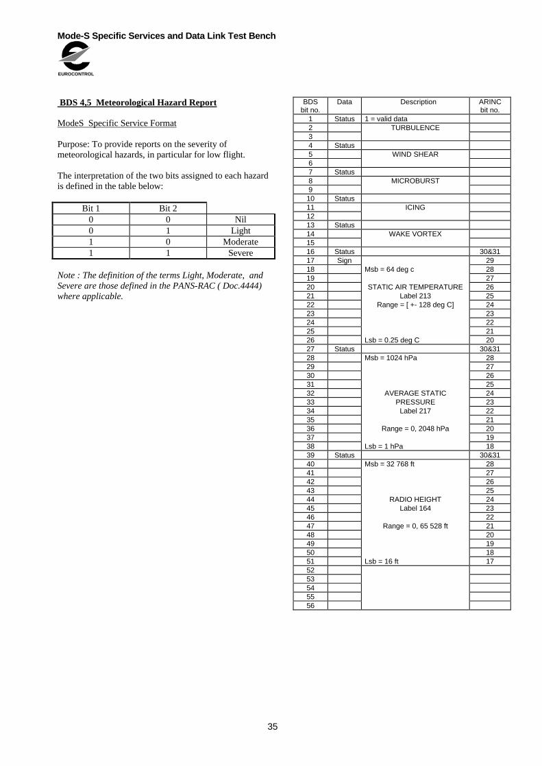
BDS 4,5 Meteorological Hazard Report
ModeS Specific Service Format
Purpose: To provide reports on the severity ofmeteorological hazards, in particular for low flight.
The interpretation of the two bits assigned to each hazardis defined in the table below:
Bit 1 Bit 20 0 Nil0 1 Light1 0 Moderate1 1 Severe
Note : The definition of the terms Light, Moderate, andSevere are those defined in the PANS-RAC ( Doc.4444)where applicable.
BDSbit no.
Data Description ARINCbit no.
1 Status 1 = valid data2 TURBULENCE34 Status5 WIND SHEAR67 Status8 MICROBURST910 Status11 ICING1213 Status14 WAKE VORTEX1516 Status 30&3117 Sign 2918 Msb = 64 deg c 2819 2720 STATIC AIR TEMPERATURE 2621 Label 213 2522 Range = [ +- 128 deg C] 2423 2324 2225 2126 Lsb = 0.25 deg C 2027 Status 30&3128 Msb = 1024 hPa 2829 2730 2631 2532 AVERAGE STATIC 2433 PRESSURE 2334 Label 217 2235 2136 Range = 0, 2048 hPa 2037 1938 Lsb = 1 hPa 1839 Status 30&3140 Msb = 32 768 ft 2841 2742 2643 2544 RADIO HEIGHT 2445 Label 164 2346 2247 Range = 0, 65 528 ft 2148 2049 1950 1851 Lsb = 16 ft 175253545556

Mode-S Specific Services and Data Link Test Bench
EUROCONTROL
36
BDS 5,0 Track and turn report
Mode S Specific Services Format
1. All references to ARINC assume that the ARINC 429standard is used.
2. The BDS servicing process will make a logical ANDof bits 30 & 31 of each ARINC parameter and insert theresult into the status bit for the corresponding parameter.
3. The maximum acceptable data age at time oftransmission to the ground is 1 s for all parameters.
4. The BDS update rate will be sufficient to ensure thatthe maximum acceptable data age of all parameters is notexceeded in normal operation.
5. If maximum acceptable data age is exceeded for anyparameter, then the status bit for that parameter shouldactively be set to 0 by the BDS processing service.
6. If the value of a parameter from the data sourceexceeds the range allowable in the BDS definition, themaximum allowable value in the correct positive ornegative sense will be used instead.
Notes:
1) The data entered into this register should, wheneverpossible, be derived from the sources that arecontrolling the aircraft.
2) This requires active intervention by the BDS servicingprocess.
3) Where ARINC 429 is used, this only relates toparameters where the most significant bit or bits havebeen omitted from the BDS format.
7. If any parameter is not available on the aircraft, all bitscorresponding to that parameter must be actively set to 0by the BDS servicing process.
Note : If any parameter becomes unavailabledue to abnormal operation, then item 5 above applies.
BDSbit no.
Databit no.
Description ARINCbit no.
1 Status 1 = valid data 30&312 Sign 1 = left (left wing down ) 293 msb = 45 deg 274 265 ROLL ANGLE 256 Label 325 247 238 Range =[ +- 90deg ] 229 2110 2011 lsb = 45/256 deg 1912 Status 1 = valid data 30&3113 Sign 1 = west ( e.g. 315 = -45 deg) 2914 msb = 90 deg 2815 2716 2617 TRUE TRACK ANGLE 2518 Label 313 2419 2320 Range =[ +- 180 deg ] 2221 2122 2023 lsb = 90/512 deg 1924 Status 1 = valid data 30&3125 msb = 1024 kts 2726 2627 2528 GROUND SPEED 2429 Label 312 2330 2231 2132 Range = [0,2046 ] 2033 1934 lsb = 2 kt 1835 1 = valid data 30&3136 1 = minus 2937 msb = 8 deg/sec 2738 2639 TRACK ANGLE RATE 2540 Label 335 2441 2342 2243 Range = [-16,+16] 2144 2045 lsb = 8/256 1946 1 = valid data 30&3147 msb = 1024 kt 2848 2749 2650 TRUE AIR SPEED 2551 Label 210 2452 2353 2254 Range =[0,2046] 2155 2056 lsb = 2 kt 19

Mode-S Specific Services and Data Link Test Bench
EUROCONTROL
37
BDS 5, 1 Position Report Coarse
ModeS Specific Service Format
PURPOSE: To provide a three-dimensional report onaircraft position.
Notes :
1) The single status bit ( bit 1 ) is to be set to 0 if any ofthe three parameters are invalid and are identical to thestatus bit in BDS 5,2.
2) The required valid range for latitude is +90 degreesto - 90 degrees, but the parameter is coded with an msbof 90 degrees to allow the use of the same codingalgorithm as for longitude.
3) The source of the information in this buffer is thesame as that indicated in the FOM/SOURCE field ofBDS 5,2.
BDSbit no.
Data Description ARINCbit no.
1 Status 1 = valid data2 Sign3 msb = 90 deg4567 LATITUDE8 Range =[ +-180 deg ]9101112131415161718192021 lsb = 360/1048576 deg22 Sign23 msb = 90 deg24252627 LONGITUDE28 Range =[ +-180 deg ]29303132333435363738394041 lsb = 360/1048576 deg42 Sign43 msb = 65536 ft44454647 PRESSURE48 ALTITUDE4950 Range = 131068 ft515253545556 lsb = 8 ft

Mode-S Specific Services and Data Link Test Bench
EUROCONTROL
38
BDS 5, 2 Position Report Fine
ModeS Specific Service Format
PURPOSE: To provide a high precisionthree-dimensional report on aircraft position, when used inconjunction with BDS 5,1. Information on the source ofdata is included.
The decimalvalue of the binary coded ( figure of merit )FOM/SOURCE parameter is to be interpreted as follows:
0 = Loss of navigational capability.1 = RNP 20 (e.g. INS data) pressure altitude.2 = RNP 5 (e.g. VOR/DME) pressure altitude3 = RNP 1 (e.g DME/DME or GNSS) pressure
altitude4 = Reserved for differential GNSS ( circular
position error (CPE) 10m) pressure altitude.5 = Reserved for differential GNSS (CPE 2.5 m)
pressure altitude.6 - 10 = Unassigned11 = RNP 1 ( e.g. DME/DME or GNSS) GNSS
height12 = Reserved for differential GNSS (CPE 10 m)
height.13 = Reserved for differential DGNSS (CPE 2.5 m)
height14-15 = Unassigned.
where RNP is required navigational performance asdefined by ICAO. Suitable RNP categories have not yetbeen defined for values below 1; therfore CPE is used.
The single status bit (bit 1) is to be set to 0 if any of thethree parameters are invalid and are identical to thestatus bit in BDS 5,1.
Notes :
1) The LATITUDE (fine) and LONGITUDE (fine)parameters are in 2’s complement coding, so they mustbe interpreted in conjunction with the correspondingparameters BDS 5,1.
2) When GNSS height is contained in the altitude field,the pressure altitude can be obtained from BDS 5,1.
BDSbit no.
Databit no.
Description ARINCbit no.
1 Status 1 = valid data23 FOM/SOURCE456 msb = 90/128 deg78910111213 LATITUDE FINE14 Range = 180/128 deg151617181920212223 lsb = 90/16777216 deg24 msb = 90/128 deg25262728293031 LONGITUDE FINE32 Range = 180/128 deg333435363738394041 lsb = 90/16777216 deg42 Sign43 msb = 65536 ft44454647 PRESSURE48 ALTITUDE4950 Range = 131068 ft515253545556 lsb = 8 ft

Mode-S Specific Services and Data Link Test Bench
EUROCONTROL
39
BDS 5,3 Air-referenced State Vector
ModeS Specific Service Format
PURPOSE: To provide the ATC system with the currentmeasured values of magnetic heading, IAS/Mach,altitude rate and TAS.
BDSbit no.
Databit no.
Description ARINCbit no.
1 Status 1 = valid data 30&312 Sign 293 msb = 90 deg 284 275 MAGNETIC HEADING 266 Label 320 257 248 Range =[ +-180 deg ] 239 2210 2111 2012 lsb = 360/2048 deg 1913 Status 1 = valid data 30&3114 msb = 512 kt 2815 2716 2617 INDICATED AIRSPEED (IAS) 2518 Label 206 2419 2320 Range = 0, 1024 kt 2221 2122 2023 lsb = 1 kt 1924 Status 1 = valid data 30&3125 msb = 2.048 2826 2727 2628 MACH NUMBER 2529 Label 205 2430 2331 Range = 0, 4.096 2232 2133 lsb = 0.008 2034 Status 1 = valid data 30&3135 msb = 1024 kt 2836 2737 2638 2539 TRUE AIRSPEED (TAS) 2440 2341 Range = 0,2048 kt 2242 2143 2044 1945 1846 lsb = 0.5 kt 1747 Status 1 = valid data 30&3148 Sign 2949 msb = 8192 ft/min 2850 2751 ALTITUDE RATE 2652 Label 212 2553 2454 Range = +- 16384 ft/min 2355 2256 msb = 64 ft/min 21

Mode-S Specific Services and Data Link Test Bench
EUROCONTROL
40
BDS 6,0 Heading and speed report
ModeS Specific Service Format
1. All references to ARINC assume that the ARINC 429standard is used.
2. The BDS servicing process will make a logical ANDof bits 30 & 31 of each ARINC parameter and insert theresult into the status bit for the corresponding parameter.
3. The maximum acceptable data age at time oftransmission to the ground is 1 s for all parameters.
4. The BDS update rate will be sufficient to ensure thatthe maximum acceptable data age of all parameters is notexceeded in normal operation.
5. If maximum acceptable data age is exceeded for anyparameter, then the status bit for that parameter shouldactively be set to 0 by the BDS processing service.
6. If the value of a parameter from the data sourceexceeds the range allowable in the BDS definition, themaximum allowable value in the correct positive ornegative sense will be used instead.
Notes:
1) The data entered into this register should, wheneverpossible, be derived from the sources that arecontrolling the aircraft.
2) This requires active intervention by the BDS servicingprocess.
3) Where ARINC 429 is used, this only relates toparameters where the most significant bit or bits havebeen omitted from the BDS format.
7. All parameters are required except for InertialVertical Velocity which will be supplied only by aircraftwith a suitable inertial source. If Inertial VerticalVelocity is not available bits 46 to 56 inclusive must beactively set to 0 by the BDS servicing process.
BDSbit no.
Databit no.
Description ARINCbit no.
1 Status 1 = valid data 30&312 Sign 1 = west 293 msb = 90 deg 284 275 MAGNETIC HEADING 266 Label 320 257 248 Range =[ +-180 deg ] 239 2210 2111 2012 lsb = 90/512 deg 1913 Status 1 = valid data 30&3114 msb = 512 kt 2815 2716 2617 INDICATED AIRSPEED 2518 Label 206 2419 2320 Range = [0, 1023] 2221 2122 2023 lsb = 1kt 1924 Status 1 = valid data 30&3125 msb = 2.048 mach 2826 2727 2628 MACH NUMBER 2529 Label 205 2430 2331 Range = [0, 4.096 ] 2232 2133 2034 lsb = 2.048/512 1935 Status 1 = valid data 30&3136 Sign 1 = below 2937 msb = 8192 ft/min 2738 2639 BAROMETRIC ALTITUDE 2540 RATE 2441 Label 212 2342 2243 Range = [-16384, +16352 ] 2144 2045 lsb = 32 ft/min 1946 Status 1 = valid data 30&3147 Sign 1 = below 2948 msb = 8192 ft/min 2749 2650 INERTIAL VERTICAL 2551 VELOCITY 2452 Label 365 2353 2254 Range = [-16384, +16352 ] 2155 2056 lsb = 32 ft/min 19