eurocode example load combinations
TRANSCRIPT

8/2/2019 Eurocode Example Load Combinations
http://slidepdf.com/reader/full/eurocode-example-load-combinations 1/15
Eurocodes – Background and Applications
Eurocode example:
Actions on a six storey building
18-20 February 2008
Prepared by:
Kirstine Bak-Kristensen
Svend Ole Hansen
8/2/2019 Eurocode Example Load Combinations
http://slidepdf.com/reader/full/eurocode-example-load-combinations 2/15
Eurocode example – actions on a six storey building 18-20 February 2008
2
TABLE OF CONTENTS
1. Introduction.................................................................................................................... 3
2. Characteristic permanent actions (G) ............................................................................. 4
3. Characteristic imposed loads (I)..................................................................................... 5
4. Characteristic wind actions (W) ..................................................................................... 8
5. Characteristic snow loads (S) ....................................................................................... 11
6. Combination of actions ................................................................................................ 12
7. Dimensioning combination of actions - STR............................................................... 14
8. Loss of static equilibrium - EQU ................................................................................. 15

8/2/2019 Eurocode Example Load Combinations
http://slidepdf.com/reader/full/eurocode-example-load-combinations 3/15
Eurocode example – actions on a six storey building 18-20 February 2008
3
1. IntroductionThe present example illustrates the Eurocode actions on a six storey building.
The characteristic actions and design actions on a six storey building are determined. The
support reactions are calculated for the actions considered. These cover permanent actions,
imposed loads, wind actions and snow loads.
The building is indefinitely long and supported per 10 m along the building in the points A
and B. The points A and B shown in figure 1.1 illustrate two points, for which the support
reactions are calculated.
The building includes residential and office areas as shown in figure 1.1. This indicates
that medium Consequence Class CC2 may be assumed, see B3.1 in EN 1990:2002.
The following recommended partial safety factors for permanent actions are applied, see
table A1.2(A) and A.1.2(B) in EN 1990:2002.
• EQU: ,supGjγ =1,10 and ,inf Gj
γ =0,90.
• STR 6.10a: ,supGjγ =1,35 and ,inf Gjγ =1,00. Permanent actions only in 6.10a.
• STR 6.10b: ,supGjξγ =1,15 and ,inf Gjγ =1,00.
The recommended partial safety factor of 1.5 is applied for all variable actions, see table
A1.2(A) and A.1.2(B) in EN 1990:2002.The reliability class RC3 with FI K =1,1 is assumed, see B3.3 in EN 1990:2002. The FI K
factor of 1,1 is applied to the partial safety factors of the unfavourable actions.
Figure 1.1 - Six storey building

8/2/2019 Eurocode Example Load Combinations
http://slidepdf.com/reader/full/eurocode-example-load-combinations 4/15
Eurocode example – actions on a six storey building 18-20 February 2008
4
2. Characteristic permanent actions (G)
The characteristic permanent actions are assumed as follows:
Distributed loads: 6,1=roof g kN/m2
4,2= floor g kN/m2
Line loads: 4,2= facadeG kN/m and 8,0 kN/m
4,2=wallG kN/m
Figure 2.1 - Characteristic permanent action
The above-mentioned permanent actions give the characteristic permanent support
reactions specified in table 2.1.
Table 2.1 - Support reactions from characteristic permanent actions
Vertical support reactions [kN]
RA [kN] 652
RB [kN] 2356

8/2/2019 Eurocode Example Load Combinations
http://slidepdf.com/reader/full/eurocode-example-load-combinations 5/15
Eurocode example – actions on a six storey building 18-20 February 2008
5
3. Characteristic imposed loads (I)The characteristic imposed uniformly distributed loads q and the load combination factors
0ψ for residential areas and office areas are as follows:
0,2=resq kN/m2
7,0,0 =resψ
0,3=off q kN/m2
7,0,0 =off ψ
The recommended floor reduction factor Aα is calculated by:
0,17
5 00 ≤+=
A
A A
ψ α
in which 0ψ is the above-mentioned load combination factor, the area 0 A =10,0 m², and A
is the loaded area. For the three cases shown below, the reduced imposed loads are given
in table 3.1 below.
Table 3.1 – Reduced imposed loads
Case no. Aα res A qα off A qα
1 0,571 1,14 1,71
2 0,625 1,25 1,88
3 0,667 1,33 2,00
The recommended multi storey reduction factor nα is calculated by:
n
nn
0)2(2 ψ α
⋅−+=
in which n is the number of storeys. Inserting the number of storeys gives:
85,04
7,0)24(2,4 =
⋅−+=resα
0,12
7,0)22(2,2 =
⋅−+=off
α
8/2/2019 Eurocode Example Load Combinations
http://slidepdf.com/reader/full/eurocode-example-load-combinations 6/15
Eurocode example – actions on a six storey building 18-20 February 2008
6
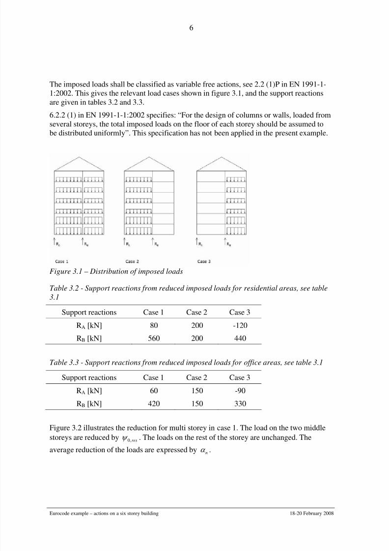
The imposed loads shall be classified as variable free actions, see 2.2 (1)P in EN 1991-1-
1:2002. This gives the relevant load cases shown in figure 3.1, and the support reactionsare given in tables 3.2 and 3.3.
6.2.2 (1) in EN 1991-1-1:2002 specifies: “For the design of columns or walls, loaded from
several storeys, the total imposed loads on the floor of each storey should be assumed to
be distributed uniformly”. This specification has not been applied in the present example.
Figure 3.1 – Distribution of imposed loads
Table 3.2 - Support reactions from reduced imposed loads for residential areas, see table3.1
Support reactions Case 1 Case 2 Case 3
RA [kN] 80 200 -120
RB [kN] 560 200 440
Table 3.3 - Support reactions from reduced imposed loads for office areas, see table 3.1
Support reactions Case 1 Case 2 Case 3
RA [kN] 60 150 -90
RB [kN] 420 150 330
Figure 3.2 illustrates the reduction for multi storey in case 1. The load on the two middle
storeys are reduced by res,0ψ . The loads on the rest of the storey are unchanged. The
average reduction of the loads are expressed by nα .

8/2/2019 Eurocode Example Load Combinations
http://slidepdf.com/reader/full/eurocode-example-load-combinations 7/15
Eurocode example – actions on a six storey building 18-20 February 2008
7
Figure 3.2 – Distribution of imposed loads with reduction for multi storey, case 1

8/2/2019 Eurocode Example Load Combinations
http://slidepdf.com/reader/full/eurocode-example-load-combinations 8/15
Eurocode example – actions on a six storey building 18-20 February 2008
8
4. Characteristic wind actions (W)The indefinitely long facades of the building are assumed to be orientated north-south.
Basic values, see 4.2 in EN 1991-1-4:2005
The fundamental value of the basic wind velocity is assumed to be 0,bv =24 m/s. For
westerly and easterly winds perpendicular to the long facades, the directional factor
squared has been assumed to be 2
dir c =1,0 and 2
dir c =0,8, respectively,
Terrain roughness, see 4.3.2 in EN 1991-1-4:2005
For westerly and easterly winds the upstream terrains are assumed to be a suburban terrain
with a roughness length of 0 z =0,30 m and a lake with a roughness length of 0 z =0,01 m,
respectively.
Wind turbulence and peak velocity pressure, see 4.4-4.5 in EN 1991-1-4:2005
The characteristic peak velocity pressures at building height 22,0 m above terrain are
given in table 4.1 assuming flat terrain. The recommended turbulence factor of I k =1,0 has
been applied.
Table 4.1 – The characteristic peak velocity pressure q p.
Wind direction Directional factor
squared 2
dir c
Terrain
category
z0 [m]r k pq
[kN/m2]
Wind from west 1,0 III 0,30 0,2154 0,810
Wind from east 0,8 I 0,01 0,1698 0,939
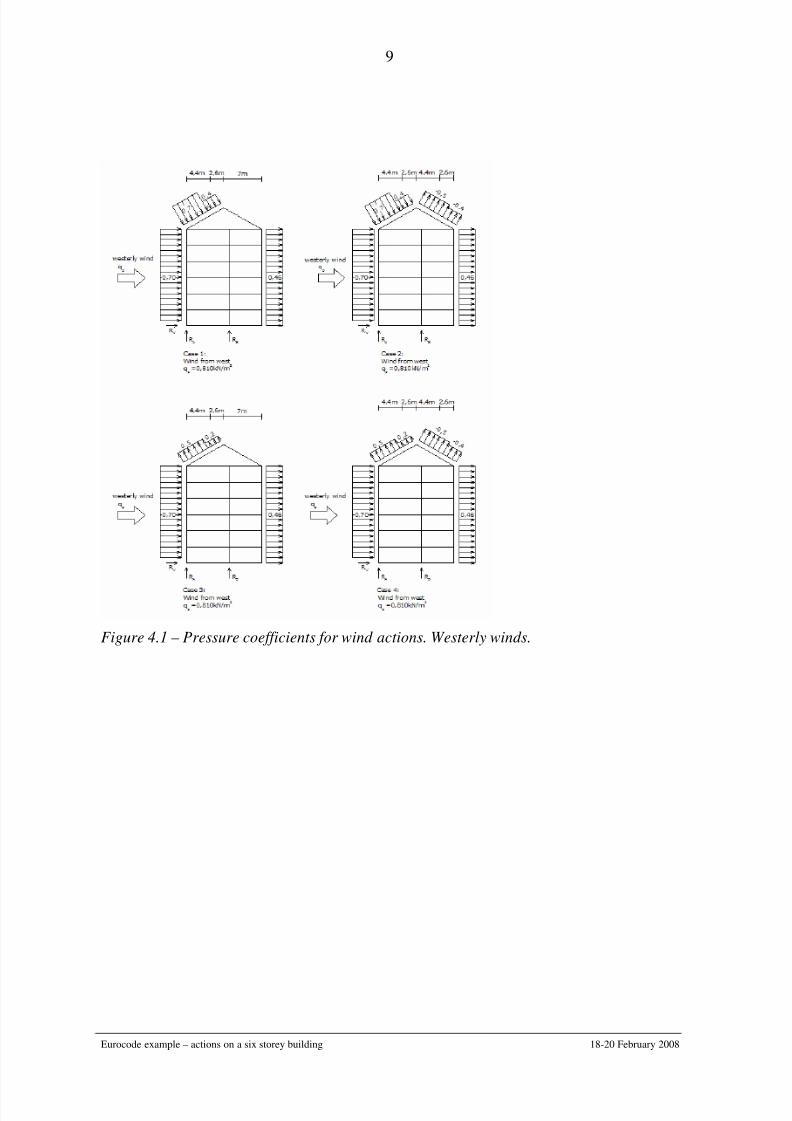
Pressure coefficients, see 7.2.2 and 7.2.5 in EN 1991-1-4:2005
The pressure coefficients for the wind action are given in figure 4.1.The lack of correlationof wind pressures between the windward and leeward side has been taken into account by
the recommended procedure, see the note of 7.2.2 (3), giving a reduction factor of 0,87.
Thus, the pressure coefficients for wind loads on the facades become 70,080,087,0 =⋅
and ( ) 46,053,087,0 −=−⋅ , respectively.
8/2/2019 Eurocode Example Load Combinations
http://slidepdf.com/reader/full/eurocode-example-load-combinations 9/15
Eurocode example – actions on a six storey building 18-20 February 2008
9
Figure 4.1 – Pressure coefficients for wind actions. Westerly winds.
8/2/2019 Eurocode Example Load Combinations
http://slidepdf.com/reader/full/eurocode-example-load-combinations 10/15
Eurocode example – actions on a six storey building 18-20 February 2008
10
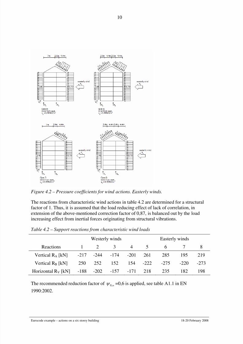
Figure 4.2 – Pressure coefficients for wind actions. Easterly winds.
The reactions from characteristic wind actions in table 4.2 are determined for a structural
factor of 1. Thus, it is assumed that the load reducing effect of lack of correlation, in
extension of the above-mentioned correction factor of 0,87, is balanced out by the load
increasing effect from inertial forces originating from structural vibrations.
Table 4.2 – Support reactions from characteristic wind loads
Westerly winds Easterly windsReactions 1 2 3 4 5 6 7 8
Vertical RA [kN] -217 -244 -174 -201 261 285 195 219
Vertical RB [kN] 250 252 152 154 -222 -275 -220 -273
Horizontal RV [kN] -188 -202 -157 -171 218 235 182 198
The recommended reduction factor of w,0ψ =0,6 is applied, see table A1.1 in EN
1990:2002.

8/2/2019 Eurocode Example Load Combinations
http://slidepdf.com/reader/full/eurocode-example-load-combinations 11/15
Eurocode example – actions on a six storey building 18-20 February 2008
11
5. Characteristic snow loads (S)
The characteristic value of snow load on the ground is assumed to be 9.0=k s kN/m².
The shape coefficient for the snow load are given in figure 5 and the reactions for the
characteristic snow load are given in table 5.1.
Figure 5.1 - Snow load shape coefficients
The recommended load combination factor for ”remainder of CEN Member States, for
sites located at altitude H ≤ 1000 m a.s.l.” is assumed, i.e. S,0ψ =0,50.
Table 5.1 - Support reactions from characteristic snow loads
Support reactions Case 1 Case 2 Case 3
RA [kN] 13 -2 20
RB [kN] 88 77 55

8/2/2019 Eurocode Example Load Combinations
http://slidepdf.com/reader/full/eurocode-example-load-combinations 12/15
Eurocode example – actions on a six storey building 18-20 February 2008
12
6. Combination of actionsExamples of possible load combinations are listed in table 6.1. The following comments
may clarify some of the load combinations:
• When the imposed load is an accompanying action, the load combination factor 0ψ is
applied and not the multi storey reduction factor nα , see 3.3.2 (2)P in EN 1991-1-
1:2002.
• When the imposed loads act simultaneously with the other variable actions due to
wind and / or snow, the total imposed loads considered in the load case shall be
considered as a single action, see 3.3.1 (2)P in EN 1991-1-1: 2002.
• When the imposed loads are the only variable action present, one of the imposed load
categories is dominating and the other is accompanying, see the load combinations
STR (6.10b)-4 and STR (6.10b)-5.
STR load combinations for largest R A and largest R B
STR 6.10b-1: SW I I G swoff off resres ,0,0 5,11,15,11,15,11,15,11,115,11,1 ψ ψ α α ⋅⋅+⋅⋅+⋅⋅+⋅⋅+⋅⋅
STR 6.10b-2: S I I W G Soff off resres ,0,0,0 5,11,15,11,15,11,15,11,115,11,1 ψ ψ ψ ⋅⋅+⋅⋅+⋅⋅+⋅⋅+⋅⋅
STR 6.10b-3: W I I SG W off off resres ,0,0,0 5,11,15,11,15,11,15,11,115,11,1 ψ ψ ψ ⋅⋅+⋅⋅+⋅⋅+⋅⋅+⋅⋅
STR 6.10b-4: off off resres I I G ,05,11,15,11,115,11,1 ψ α ⋅⋅+⋅⋅+⋅⋅
STR 6.10b-5: resresoff off I I G ,05,11,15,11,115,11,1 ψ α ⋅⋅+⋅⋅+⋅⋅
STR 6.10a: G⋅⋅ 35,11,1
STR load combinations for smallest R A (permanent action favourable)
STR 6.10b-6: SW I I G SW off off resres ,0,0 5,11,15,11,15,11,15,11,10,1 ψ ψ α α ⋅⋅+⋅⋅+⋅⋅+⋅⋅+⋅
STR 6.10b-7: S I I W G Soff off resres ,0,0,0 5,11,15,11,15,11,15,11,10,1 ψ ψ ψ ⋅⋅+⋅⋅+⋅⋅+⋅⋅+⋅
STR 6.10b-8: W I I SG W off off resres ,0,0,0 5,11,15,11,15,11,15,11,10,1 ψ ψ ψ ⋅⋅+⋅⋅+⋅⋅+⋅⋅+⋅
STR 6.10b-9: W G ⋅⋅+⋅ 5,11,10,1
STR load combinations for smallest R B (permanent action favourable)
STR 6.10b-10: W G ⋅⋅+⋅ 5,11,10,1
8/2/2019 Eurocode Example Load Combinations
http://slidepdf.com/reader/full/eurocode-example-load-combinations 13/15
Eurocode example – actions on a six storey building 18-20 February 2008
13
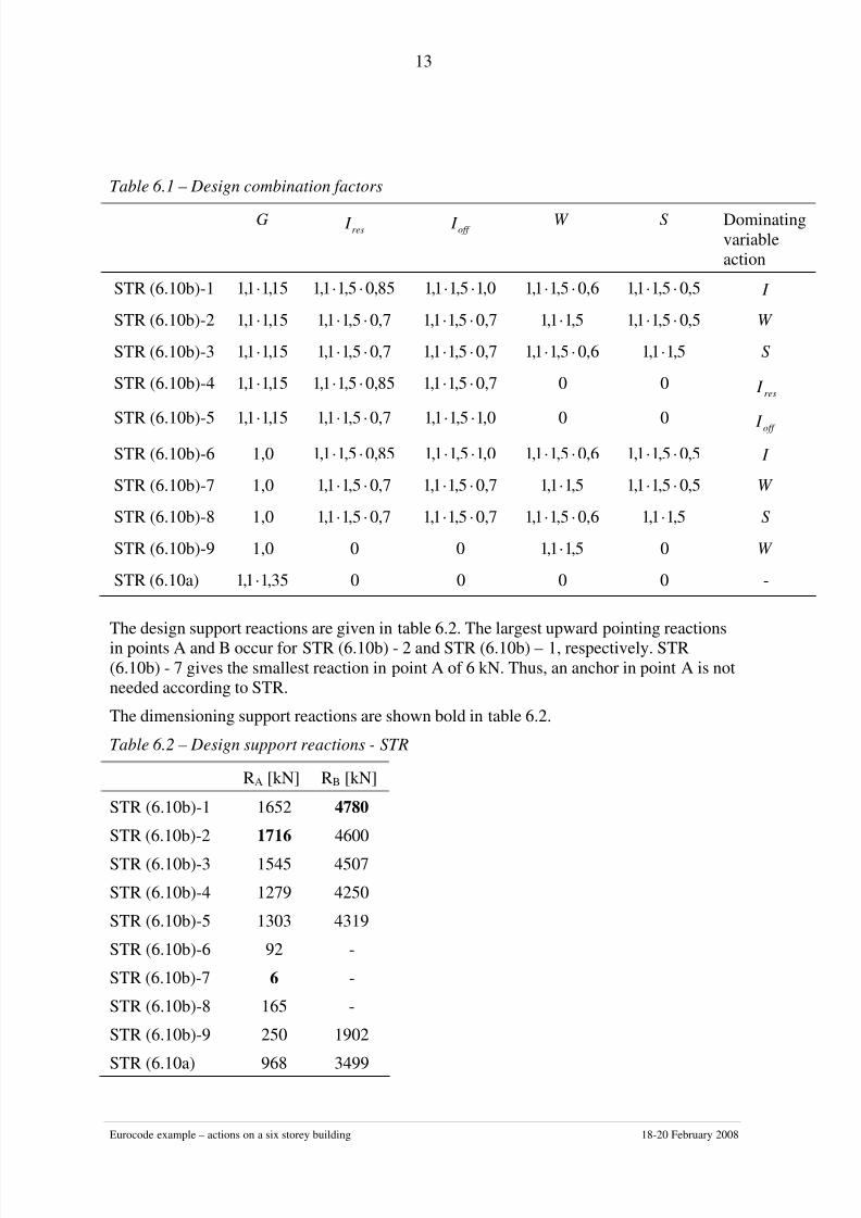
Table 6.1 – Design combination factors
G res I off I W S Dominating
variable
action
STR (6.10b)-1 15,11,1 ⋅ 85,05,11,1 ⋅⋅ 0,15,11,1 ⋅⋅ 6,05,11,1 ⋅⋅ 5,05,11,1 ⋅⋅ I
STR (6.10b)-2 15,11,1 ⋅ 7,05,11,1 ⋅⋅ 7,05,11,1 ⋅⋅ 5,11,1 ⋅ 5,05,11,1 ⋅⋅ W
STR (6.10b)-3 15,11,1 ⋅ 7,05,11,1 ⋅⋅ 7,05,11,1 ⋅⋅ 6,05,11,1 ⋅⋅ 5,11,1 ⋅ S
STR (6.10b)-4 15,11,1 ⋅ 85,05,11,1 ⋅⋅ 7,05,11,1 ⋅⋅ 0 0res I
STR (6.10b)-5 15,11,1⋅
7,05,11,1⋅⋅
0,15,11,1⋅⋅
0 0 off I
STR (6.10b)-6 1,0 85,05,11,1 ⋅⋅ 0,15,11,1 ⋅⋅ 6,05,11,1 ⋅⋅ 5,05,11,1 ⋅⋅ I
STR (6.10b)-7 1,0 7,05,11,1 ⋅⋅ 7,05,11,1 ⋅⋅ 5,11,1 ⋅ 5,05,11,1 ⋅⋅ W
STR (6.10b)-8 1,0 7,05,11,1 ⋅⋅ 7,05,11,1 ⋅⋅ 6,05,11,1 ⋅⋅ 5,11,1 ⋅ S
STR (6.10b)-9 1,0 0 0 5,11,1 ⋅ 0 W
STR (6.10a) 35,11,1 ⋅ 0 0 0 0 -
The design support reactions are given in table 6.2. The largest upward pointing reactions
in points A and B occur for STR (6.10b) - 2 and STR (6.10b) – 1, respectively. STR
(6.10b) - 7 gives the smallest reaction in point A of 6 kN. Thus, an anchor in point A is not
needed according to STR.
The dimensioning support reactions are shown bold in table 6.2.
Table 6.2 – Design support reactions - STR
RA [kN] RB [kN]
STR (6.10b)-1 1652 4780
STR (6.10b)-2 1716 4600
STR (6.10b)-3 1545 4507
STR (6.10b)-4 1279 4250
STR (6.10b)-5 1303 4319
STR (6.10b)-6 92 -
STR (6.10b)-7 6 -
STR (6.10b)-8 165 -
STR (6.10b)-9 250 1902
STR (6.10a) 968 3499
8/2/2019 Eurocode Example Load Combinations
http://slidepdf.com/reader/full/eurocode-example-load-combinations 14/15
Eurocode example – actions on a six storey building 18-20 February 2008
14
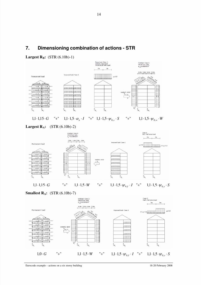
7. Dimensioning combination of actions - STRLargest RB: (STR (6.10b)-1)
G⋅⋅ 15,11,1 ""+ I n ⋅⋅⋅ α 5,11,1 ""+ Ss ⋅⋅⋅ ,05,11,1 ψ ""+ W w ⋅⋅⋅ ,05,11,1 ψ
Largest RA: (STR (6.10b)-2)
G⋅⋅ 15,11,1 ""+ W ⋅⋅ 5,11,1 ""+ I I ⋅⋅⋅ ,05,11,1 ψ ""+ Ss ⋅⋅⋅ ,05,11,1 ψ
Smallest RA: (STR (6.10b)-7)
G⋅0,1 ""+ W ⋅⋅ 5,11,1 ""+ I I ⋅⋅⋅ ,05,11,1 ψ ""+ Ss ⋅⋅⋅ ,05,11,1 ψ

8/2/2019 Eurocode Example Load Combinations
http://slidepdf.com/reader/full/eurocode-example-load-combinations 15/15
Eurocode example – actions on a six storey building 18-20 February 2008
15
8. Loss of static equilibrium - EQU
The design support reaction in EQU is given in table 8.1.
Table 8.1 – Design support reaction - EQU
RA [kN] RB [kN]
EQU -153 -
inf sup 9,010,1 GG ⋅+⋅ ""+ W ⋅⋅ 5,11,1 ""+ I i ⋅⋅⋅ ,05,11,1 ψ ""+ Ss ⋅⋅⋅ ,05,11,1 ψ
6.4.1 (1)P in EN 1990:2002 specifies:
“EQU : Loss of static equilibrium of the structure or any part of it considered as a rigid
body, where:
• minor variations in the value or the spatial distribution of actions from a single source
are significant, and
• the strengths of construction materials or ground are generally not governing”
Is EQU relevant in the present example?
If yes, how should the anchor be designed?
Give STR alone sufficient safety if an anchor is chosen in the first place?