eurocode basis of structural and geotechnical design · • en 1997 eurocode 7: geotechnical design...
TRANSCRIPT
Document type: European Standard Document subtype: Document stage: Working Document Document language: E https://standardnorge1-my.sharepoint.com/personal/by220_standard_no/Documents/Mine Dokumenter/CEN/TC250/SC10/Standard document/prEN 1990 Third revised draft from Management Group 2019_09_11 Clean version.docx STD Version 2.9a
CEN/TC 250 Date: 2019-09
prEN 1990:2019
CEN/TC 250
Secretariat: BSI
Eurocode — Basis of structural and geotechnical design
Eurocode — Grundlagen der Tragwerksplanung
Eurocodes — Bases de calcul des structures
ICS:
Descriptors:
prEN 1990:2019 (E)
2
Contents
Page
European foreword ....................................................................................................................................................... 7
Introduction .................................................................................................................................................................... 7
1 Scope .................................................................................................................................................................... 9 1.1 Scope of EN 1990 ............................................................................................................................................. 9 1.2 Assumptions ...................................................................................................................................................... 9
2 Normative references ................................................................................................................................. 10
3 Terms, definitions and symbols .............................................................................................................. 10 3.1 Terms and definitions ................................................................................................................................ 10 3.1.1 Common terms used in the Eurocodes ................................................................................................. 12 3.1.2 Terms relating to design ............................................................................................................................ 13 3.1.3 Terms relating to actions .......................................................................................................................... 16 3.1.4 Terms relating to material and product properties ........................................................................ 19 3.1.5 Terms relating to geometrical data ....................................................................................................... 20 3.1.6 Terms relating to structural and geotechnical analysis ................................................................ 20 3.2 Symbols and abbreviations ...................................................................................................................... 21 3.2.1 Latin upper-case letters ............................................................................................................................. 21 3.2.2 Latin lower-case letters ............................................................................................................................. 23 3.2.3 Greek upper-case letters ........................................................................................................................... 24 3.2.4 Greek lower-case letters ............................................................................................................................ 24
4 General rules .................................................................................................................................................. 25 4.1 Basic requirements ..................................................................................................................................... 25 4.2 Structural reliability ................................................................................................................................... 25 4.3 Consequences of failure ............................................................................................................................. 26 4.4 Robustness...................................................................................................................................................... 27 4.5 Design service life ........................................................................................................................................ 27 4.6 Durability ........................................................................................................................................................ 28 4.7 Sustainability ................................................................................................................................................. 28 4.8 Quality Management ................................................................................................................................... 28
5 Principles of limit state design ................................................................................................................ 29 5.1 General ............................................................................................................................................................. 29 5.2 Design situations .......................................................................................................................................... 29 5.3 Ultimate limit states (ULS) ........................................................................................................................ 30 5.4 Serviceability limit states (SLS) .............................................................................................................. 30 5.5 Structural and load models ...................................................................................................................... 31
6 Basic variables .............................................................................................................................................. 32 6.1 Actions and environmental influences ................................................................................................. 32 6.1.1 Classification of actions ............................................................................................................................. 32 6.1.2 Representative values of actions ............................................................................................................ 32 6.1.3 Specific types of action ............................................................................................................................... 35 6.1.4 Environmental influences ......................................................................................................................... 37 6.2 Material and product properties ............................................................................................................ 37 6.3 Geometrical parameters ............................................................................................................................ 38
prEN 1990:2019 (E)
3
7 Structural analysis and design assisted by testing ........................................................................... 38 7.1 Structural modelling.................................................................................................................................... 38 7.1.1 General ............................................................................................................................................................. 38 7.1.2 Static actions................................................................................................................................................... 38 7.1.3 Dynamic actions ............................................................................................................................................ 39 7.1.4 Actions inducing fatigue ............................................................................................................................. 39 7.1.5 Fire design ....................................................................................................................................................... 39 7.2 Analysis ............................................................................................................................................................ 40 7.2.1 Linear Analysis .............................................................................................................................................. 40 7.2.2 Non-linear analysis ...................................................................................................................................... 40 7.3 Design assisted by testing .......................................................................................................................... 41
8 Verification by the partial factor method ............................................................................................ 41 8.1 General ............................................................................................................................................................. 41 8.2 Limitations ...................................................................................................................................................... 42 8.3 Verification of ultimate limit states (ULS) ........................................................................................... 42 8.3.1 General ............................................................................................................................................................. 42 8.3.2 Design values of the effects of actions ................................................................................................... 43 8.3.3 Design values of actions ............................................................................................................................. 45 8.3.4 Combination of actions ............................................................................................................................... 47 8.3.5 Design values of resistance ....................................................................................................................... 51 8.3.6 Design values of material properties .................................................................................................... 53 8.3.7 Design values of geometrical data .......................................................................................................... 54 8.4 Verification of serviceability limit states (SLS).................................................................................. 55 8.4.1 General ............................................................................................................................................................. 55 8.4.2 Design values of the effects of actions ................................................................................................... 55 8.4.3 Combinations of actions ............................................................................................................................. 55 8.4.4 Design criteria ............................................................................................................................................... 57 8.4.5 Design values of geometrical data .......................................................................................................... 57
(normative) Application rules ............................................................................................................. 58 A.1 General application and application for buildings ........................................................................... 58 A.1.1 Field of application....................................................................................................................................... 58 A.1.2 Terms and definitions specifically for Annex A.1 ............................................................................. 58 A.1.3 Consequence classes .................................................................................................................................... 58 A.1.4 Design service life ......................................................................................................................................... 59 A.1.5 Actions .............................................................................................................................................................. 59 A.1.6 Combinations of actions ............................................................................................................................. 59 A.1.7 Partial factors for ultimate limit states (ULS) .................................................................................... 63 A.1.8 Serviceability criteria .................................................................................................................................. 66 A.2 Application for bridges ............................................................................................................................... 73 A.2.1 Field of application....................................................................................................................................... 73 A.2.2 Terms and definitions specifically for Annex A.2 ............................................................................. 73 A.2.3 Design service life ......................................................................................................................................... 73 A.2.4 Consequence classes .................................................................................................................................... 73 A.2.5 Actions .............................................................................................................................................................. 73 A.2.6 Combinations of actions (including psi values) ................................................................................. 73 A.2.7 Partial factors ................................................................................................................................................. 73 A.2.8 Serviceability criteria .................................................................................................................................. 73 A.2.9 Fatigue .............................................................................................................................................................. 73 A.3 Application for towers, masts and chimneys ...................................................................................... 73 A.3.1 Field of application....................................................................................................................................... 73 A.3.2 Terms and definitions specifically for Annex A.3 ............................................................................. 73 A.3.3 Consequence classes .................................................................................................................................... 73
prEN 1990:2019 (E)
4
A.3.4 Design service life ........................................................................................................................................ 73 A.3.5 Actions .............................................................................................................................................................. 73 A.3.6 Combinations of actions (including values) ................................................................................... 73 A.3.7 Partial factors ................................................................................................................................................ 73 A.3.8 Serviceability criteria ................................................................................................................................. 73 A.3.9 Fatigue .............................................................................................................................................................. 73 A.4 Application for silos and tanks ................................................................................................................ 74 A.4.1 Field of application ...................................................................................................................................... 74 A.4.2 Terms and definitions specifically for Annex A.4 ............................................................................. 74 A.4.3 Consequence classes ................................................................................................................................... 74 A.4.4 Design service life ........................................................................................................................................ 74 A.4.5 Actions .............................................................................................................................................................. 74 A.4.6 Combinations of actions ............................................................................................................................ 74 A.4.7 Partial factors ................................................................................................................................................ 74 A.4.8 Serviceability criteria ................................................................................................................................. 74 A.4.9 Fatigue .............................................................................................................................................................. 74 A.5 Application for structures supporting cranes ................................................................................... 74 A.5.1 Scope and field of application .................................................................................................................. 74 A.5.2 Terms and definitions specifically for Annex A.5 ............................................................................. 74 A.5.3 Consequence classes ................................................................................................................................... 74 A.5.4 Design service life ........................................................................................................................................ 74 A.5.5 Actions .............................................................................................................................................................. 74 A.5.6 Combinations of actions ............................................................................................................................ 74 A.5.7 Partial factors ................................................................................................................................................ 74 A.5.8 Serviceability criteria ................................................................................................................................. 74 A.5.9 Fatigue .............................................................................................................................................................. 74 A.6 Application for marine coastal structures .......................................................................................... 75 A.6.1 Field of application ...................................................................................................................................... 75 A.6.2 Terms and definitions specifically for Annex A.6 ............................................................................. 75 A.6.3 Design service life ........................................................................................................................................ 75 A.6.4 Consequence Classes ................................................................................................................................... 75 A.6.5 Actions .............................................................................................................................................................. 75 A.6.6 Combinations of actions (including psi values) ................................................................................ 75 A.6.7 Partial Factors ............................................................................................................................................... 75 A.6.8 Serviceability criteria ................................................................................................................................. 75 A.6.9 Fatigue .............................................................................................................................................................. 75
(informative) Technical management measures for design and execution ....................... 76 B.1 Use of this informative Annex .................................................................................................................. 76 B.2 Scope and field of application .................................................................................................................. 76 B.3 Choice of technical management measures........................................................................................ 76 B.4 Design quality ................................................................................................................................................ 76 B.5 Design checking ............................................................................................................................................ 77 B.6 Execution quality .......................................................................................................................................... 78 B.7 Inspection during execution .................................................................................................................... 78 B.8 Technical management measures.......................................................................................................... 79
(informative) Reliability analysis and code calibration ............................................................ 80 C.1 Use of this informative Annex .................................................................................................................. 80 C.2 Scope and field of application .................................................................................................................. 80 C.3 Basis for reliability analysis and partial factor design ................................................................... 80 C.3.1 Overview of reliability verification approaches ............................................................................... 80 C.3.2 Uncertainty representation and modelling ........................................................................................ 82 C.3.3 Reliability-based design ............................................................................................................................ 83
prEN 1990:2019 (E)
5
C.3.4 Reliability requirements ............................................................................................................................ 85 C.4 Approach for calibration of design values ........................................................................................... 87 C.4.1 Reliability requirements for reliability-based code calibration ................................................. 87 C.4.2 Partial factor design format and code parameters .......................................................................... 87 C.4.3 Partial factors ................................................................................................................................................. 88 C.4.4 Basis for calibration of design values .................................................................................................... 89 C.4.5 Combination of variable actions ............................................................................................................. 91
(informative) Design assisted by testing ......................................................................................... 94 D.1 Use of this informative Annex .................................................................................................................. 94 D.2 Scope and field of application .................................................................................................................. 94 D.3 Symbols ............................................................................................................................................................ 94 D.3.1 Latin upper-case letters ............................................................................................................................. 94 D.3.2 Latin lower-case letters .............................................................................................................................. 95 D.3.3 Greek upper-case letters ............................................................................................................................ 96 D.3.4 Greek lower-case letters ............................................................................................................................ 96 D.4 Types of tests .................................................................................................................................................. 96 D.5 Planning of tests ............................................................................................................................................ 97 D.5.1 General ............................................................................................................................................................. 97 D.5.2 Objectives and scope ................................................................................................................................... 98 D.5.3 Influencing parameters and potential failure modes ...................................................................... 98 D.5.4 Specification of test specimens and sampling .................................................................................... 98 D.5.5 Testing arrangement ................................................................................................................................... 99 D.5.6 Loading specifications ................................................................................................................................ 99 D.5.7 Details of measurements ........................................................................................................................... 99 D.5.8 Method of evaluation ................................................................................................................................ 100 D.5.9 Method of reporting test results .......................................................................................................... 100 D.6 Derivation of characteristic or design values .................................................................................. 100 D.7 General principles for statistical evaluations ................................................................................. 101 D.8 Statistical determination of a single property ................................................................................ 102 D.8.1 General .......................................................................................................................................................... 102 D.8.2 Assessment via the characteristic value............................................................................................ 102 D.8.3 Direct assessment of the design value for ULS verifications ...................................................... 103 D.9 Statistical determination of resistance models .............................................................................. 104 D.9.1 General .......................................................................................................................................................... 104 D.9.2 Standard evaluation procedure for Method A ................................................................................. 105 D.9.3 Standard evaluation procedure for Method B ................................................................................. 109 D.9.4 Use of additional prior knowledge ...................................................................................................... 110
(informative) Additional guidance for enhancing the robustness of buildings and bridges ........................................................................................................................................................... 112
E.1 Use of this informative Annex ............................................................................................................... 112 E.2 Scope and field of application ............................................................................................................... 112 E.3 Design strategies ........................................................................................................................................ 113 E.4 Design methods .......................................................................................................................................... 113
(informative) Rain-flow and reservoir counting methods for the determination of stress ranges due to high-cycle fatigue .............................................................................................. 116
F.1 Use of this informative Annex ............................................................................................................... 116 F.2 Scope and field of application ............................................................................................................... 116 F.3 Rain-flow counting method .................................................................................................................... 116 F.4 Reservoir counting method ................................................................................................................... 118
(Normative) Basis of design for bearings ..................................................................................... 120

prEN 1990:2019 (E)
6
(Informative) Verifications concerning vibration of footbridges due to pedestrian traffic .............................................................................................................................................................. 121
Bibliography ............................................................................................................................................................... 122
prEN 1990:2019 (E)
7
European foreword
This document (prEN 1990:2019) has been prepared by Technical Committee CEN/TC 250 “Structural Eurocodes”, the secretariat of which is held by BSI. CEN/TC 250 is responsible for all Structural Eurocodes and has been assigned responsibility for structural and geotechnical design matters by CEN.
This document will supersede EN 1990:2002+A1:2005.
The first generation of EN Eurocodes was published between 2002 and 2007. This document forms part of the second generation of the Eurocodes, which have been prepared under Mandate M/515 issued to CEN by the European Commission and the European Free Trade Association.
The Eurocodes have been drafted to be used in conjunction with relevant execution, material, product and test standards, and to identify requirements for execution, materials, products and testing that are relied upon by the Eurocodes.
The Eurocodes recognise the responsibility of each Member State and have safeguarded their right to determine values related to regulatory safety matters at national level through the use of National Annexes.
Introduction
0.1 Introduction to the Eurocodes
The Structural Eurocodes comprise the following standards generally consisting of a number of Parts:
• EN 1990 Eurocode: Basis of structural and geotechnical design • EN 1991 Eurocode 1: Actions on structures • EN 1992 Eurocode 2: Design of concrete structures • EN 1993 Eurocode 3: Design of steel structures • EN 1994 Eurocode 4: Design of composite steel and concrete structures • EN 1995 Eurocode 5: Design of timber structures • EN 1996 Eurocode 6: Design of masonry structures • EN 1997 Eurocode 7: Geotechnical design • EN 1998 Eurocode 8: Design of structures for earthquake resistance • EN 1999 Eurocode 9: Design of aluminium structures • <New parts>
0.2 Introduction to EN 1990
This document gives the principles and requirements for safety, serviceability, and durability of structures that are common to all Eurocodes parts and are to be applied when using them.
This document is addressed to all parties involved in construction activities (e.g. public authorities, clients, designers, contractors, producers, consultants, etc.).
0.3 Verbal forms used in the Eurocodes

prEN 1990:2019 (E)
8
The verb “shall" expresses a requirement strictly to be followed and from which no deviation is permitted in order to comply with the Eurocodes.
The verb “should” expresses a highly recommended choice or course of action. Subject to national regulation and/or any relevant contractual provisions, alternative approaches could be used/adopted where technically justified.
The verb “may" expresses a course of action permissible within the limits of the Eurocodes.
The verb “can" expresses possibility and capability; it is used for statements of fact and clarification of concepts.
0.4 National Annex for EN 1990
This document gives values within notes indicating where national choices can be made. Therefore, the National Standard implementing EN 1990 can have a National Annex containing all Nationally Determined Parameters to be used for the design of buildings and civil engineering works to be constructed in the relevant country.
National choice is allowed in EN 1990 through the following clauses:
— In main text through 4.2(3) Note 1, 4.3(1) Note Table 4.1, 4.4(2) Note, 4.5(1) Note Table 4.2, 6.1.4.2(4) Notes 1 to 4, 6.1.4.2(5) Note, 7.1.5(7) Note, 8.3.3.1(5) Note, 8.3.3.5(1) Note, 8.3.7.2(2) Notes 1 and 2, 8.3.7.3(2) Note 2;
— In Annex A.1 through A.1.3(1) Note 1 Table A.1.1, A.1.4(1) Notes 1 and 2 Table A.1.2, A.1.6.1(1) Table A.1.3, A.1.6.1(1) Notes 1 and 3, A.1.6.3(1) Note Table A.1.7, A.1.7.1(1) Note 1 Table A.1.8 and Note 2 Table A.1.9, A.1.8.2.2(1) Note 2 Table A.1.10, A.1.8.2.3(1) Note Table A.1.11, A.1.8.4(2) Note Tabla A.1.16, A.1.8.4(3) Note Table A.1.13, Table A.1.14 and Table A.1.15.
National choice is allowed in EN 1990 on the use of the following informative annexes.
— Annex B (informative) Technical management measures for design and execution;
— Annex C (informative) Reliability analysis and code calibration;
— Annex D (informative) Design assisted by testing;
— Annex E (informative) Additional guidance for enhancing the robustness of buildings and bridges ;
— Annex F (informative) Rain-flow and reservoir counting methods for the determination of stress ranges due to high cycle fatigue.
The National Annex can contain, directly or by reference, non-contradictory complementary information for ease of implementation, provided it does not alter any provisions of the Eurocodes.
prEN 1990:2019 (E)
9
1 Scope
1.1 Scope of EN 1990
(1) This document establishes principles and requirements for the safety, serviceability, robustness and durability of structures, including geotechnical structures, appropriate to the consequences of failure.
(2) This document is intended to be used in conjunction with the other Eurocodes for the design of buildings and civil engineering works, including temporary structures.
(3) This document describes the basis for structural and geotechnical design and verification according to the limit state principle.
(4) Design and verification in this document are based primarily on the partial factor method.
NOTE 1 Alternative methods are given in the other Eurocodes for specific applications.
NOTE 2 The Annexes to this document also provide general guidance concerning the use of alternative methods.
(5) This document is also applicable for:
— structural appraisal of existing construction;
— developing the design of repairs, improvements and alterations;
— assessing changes of use.
(6) This document is applicable for the design of structures where materials or actions outside the scope of EN 1991 to EN 1999 are involved.
NOTE In this case additional or amended provisions can be necessary.
1.2 Assumptions
(1) It is assumed that reasonable skill and care appropriate to the circumstances is exercised in the design, based on the knowledge and good practice generally available at the time the structure is designed.
(2) It is assumed that the design of the structure is made by appropriately qualified and experienced personnel.
(3) The design rules provided in the Eurocodes assume that:
— execution will be carried out by personnel having appropriate skill and experience;
— adequate control and supervision will be provided during design and execution of the works, whether in factories, plants, or on site;
— construction materials and products will be used as specified in the Eurocodes, in the relevant product and execution standards, and project specifications;
— the structure will be adequately maintained;
— the structure will be used in accordance with the design assumptions.
prEN 1990:2019 (E)
10
NOTE Guidance on management measures to satisfy the assumptions for design and execution is given in Annex B.
2 Normative references
The following documents are referred to in the text in such a way that some or all of their content constitutes requirements of this document. For dated references, only the edition cited applies. For undated references, the latest edition of the referenced document (including any amendments) applies.
EN 1991 (all parts), Eurocode 1: Actions on structures
EN 1992 (all parts), Eurocode 2: Design of concrete structures
EN 1993 (all parts), Eurocode 3: Design of steel structures
EN 1994 (all parts), Eurocode 4: Design of composite steel and concrete structure
EN 1995 (all parts), Eurocode 5: Design of timber structures
EN 1996 (all parts), Eurocode 6: Design of masonry structures
EN 1997 (all parts), Eurocode 7: Geotechnical design
EN 1998 (all parts), Eurocode 8: Design of structures for earthquake resistance
EN 1999 (all parts), Eurocode 9: Design of aluminium structures
3 Terms, definitions and symbols
3.1 Terms and definitions
For the purposes of this document, the following terms and definitions apply.
— ISO and IEC maintain terminological databases for use in standardization at the following addresses: IEC Electropedia: available at http://www.electropedia.org/
— ISO Online browsing platform: available at http://www.iso.org/obp
NOTE Table 3.1 lists the terms defined hereafter in alphabetical order with reference to the number hereafter where they are defined (different table for each language).
prEN 1990:2019 (E)
11
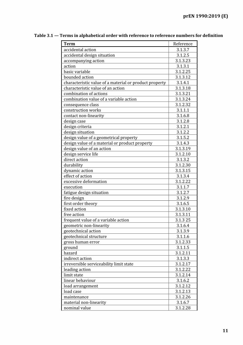
Table 3.1 — Terms in alphabetical order with reference to reference numbers for definition
Term Reference
accidental action 3.1.3.7 accidental design situation 3.1.2.5 accompanying action 3.1.3.23 action 3.1.3.1 basic variable 3.1.2.25 bounded action 3.1.3.12 characteristic value of a material or product property 3.1.4.1 characteristic value of an action 3.1.3.18 combination of actions 3.1.3.21 combination value of a variable action 3.1.3.24 consequence class 3.1.2.32 construction works 3.1.1.1 contact non-linearity 3.1.6.8 design case 3.1.2.8 design criteria 3.1.2.1 design situation 3.1.2.2 design value of a geometrical property 3.1.5.2 design value of a material or product property 3.1.4.3 design value of an action 3.1.3.19 design service life 3.1.2.10 direct action 3.1.3.2 durability 3.1.2.30 dynamic action 3.1.3.15 effect of action 3.1.3.4 excessive deformation 3.1.2.22 execution 3.1.1.7 fatigue design situation 3.1.2.7 fire design 3.1.2.9 first order theory 3.1.6.5 fixed action 3.1.3.10 free action 3.1.3.11 frequent value of a variable action 3.1.3 25 geometric non-linearity 3.1.6.4 geotechnical action 3.1.3.9 geotechnical structure 3.1.1.6 gross human error 3.1.2.33 ground 3.1.1.5 hazard 3.1.2.11 indirect action 3.1.3.3 irreversible serviceability limit state 3.1.2.17 leading action 3.1.2.22 limit state 3.1.2.14 linear behaviour 3.1.6.2 load arrangement 3.1.2.12 load case 3.1.2.13 maintenance 3.1.2.26 material non-linearity 3.1.6.7 nominal value 3.1.2.28

prEN 1990:2019 (E)
12
nominal value of a geometrical property 3.1.5.1 non-linear behaviour 3.1.6.3 non-linearity of the limit state function 3.1.6.9 permanent action 3.1.3.5 persistent design situation 3.1.2.3 quasi-permanent value of a variable action 3.1.3.26 quasi-static action 3.1.3.16 reference period 3.1.3.20 reliability differentiation 3.1.2.24 repair 3.1.2.27 representative value of a material or product property 3.1.4.2 representative value of an action 3.1.3.17 resistance 3.1.2.20 reversible serviceability limit state 3.1.2.18 robustness 3.1.2.29 second order theory 3.1.6.6 seismic action 3.1.3.8 seismic design situation 3.1.2.6 serviceability criterion 3.1.2.19 serviceability limit state 3.1.2.16 single action 3.1.3.13 static action 3.1.3.14 strength 3.1.2.21 stress history 3.1.6.10 structural analysis 3.1.6.1 structural member 3.1.1.3 structural or geotechnical model 3.1.1.4 structural reliability 3.1.2.23 structure 3.1.1.2 sustainability 3.1.2.31 transient design situation 3.1.2.4 ultimate limit state 3.1.2.15 variable action 3.1.3.6
3.1.1 Common terms used in the Eurocodes
3.1.1.1 construction works everything that is constructed or results from construction operations
Note 1 to entry: The term covers both buildings and civil engineering works. It refers to the complete construction works comprising structural members, geotechnical elements and elements other than structural.
3.1.1.2 structure part of the construction works that provides stability, resistance, and rigidity against various actions
Note 1 to entry: This definition includes structures that comprise one member or a combination of connected members.

prEN 1990:2019 (E)
13
3.1.1.3 structural member physically distinguishable part of a structure, e.g. column, beam, plate, foundation
3.1.1.4 structural or geotechnical model physical, mathematical, or numerical idealisation of the structural or geotechnical system used for the purposes of analysis, design, and verification
3.1.1.5 ground soil, rock, and fill existing in place prior to the execution of construction works
[SOURCE: ISO 6707-1:2017, 3.4.2.1]
3.1.1.6 geotechnical structure a structure that includes ground or a structural member that relies on the ground for resistance
3.1.1.7 execution all activities carried out for the physical completion of the work including procurement, the inspection and documentation thereof
Note 1 to entry: The term covers work on site; it can also signify the fabrication of parts off site and their subsequent erection on site.
3.1.2 Terms relating to design
3.1.2.1 design criteria quantitative formulations describing the conditions to be fulfilled for each limit state
3.1.2.2 design situation physical conditions that could occur during a certain time period for which it must be demonstrated, with sufficient reliability, that relevant limit states are not exceeded
3.1.2.3 persistent design situation normal condition of use or exposure of the structure
Note 1 to entry: The duration of a persistent design situation is of the same order as the design service life of the structure.
3.1.2.4 transient design situation temporary conditions of use or exposure of the structure that are relevant during a period much shorter than the design service life of the structure
Note 1 to entry: A transient design situation refers to temporary conditions of the structure, of use, or exposure, e.g. during construction or repair or under dynamic loads.
prEN 1990:2019 (E)
14
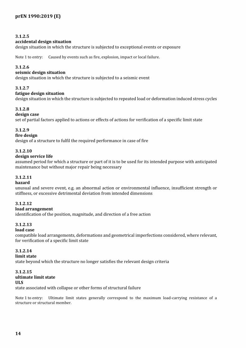
3.1.2.5 accidental design situation design situation in which the structure is subjected to exceptional events or exposure
Note 1 to entry: Caused by events such as fire, explosion, impact or local failure.
3.1.2.6 seismic design situation design situation in which the structure is subjected to a seismic event
3.1.2.7 fatigue design situation design situation in which the structure is subjected to repeated load or deformation induced stress cycles
3.1.2.8 design case set of partial factors applied to actions or effects of actions for verification of a specific limit state
3.1.2.9 fire design design of a structure to fulfil the required performance in case of fire
3.1.2.10 design service life assumed period for which a structure or part of it is to be used for its intended purpose with anticipated maintenance but without major repair being necessary
3.1.2.11 hazard unusual and severe event, e.g. an abnormal action or environmental influence, insufficient strength or stiffness, or excessive detrimental deviation from intended dimensions
3.1.2.12 load arrangement identification of the position, magnitude, and direction of a free action
3.1.2.13 load case compatible load arrangements, deformations and geometrical imperfections considered, where relevant, for verification of a specific limit state
3.1.2.14 limit state state beyond which the structure no longer satisfies the relevant design criteria
3.1.2.15 ultimate limit state ULS state associated with collapse or other forms of structural failure
Note 1 to entry: Ultimate limit states generally correspond to the maximum load-carrying resistance of a structure or structural member.
prEN 1990:2019 (E)
15
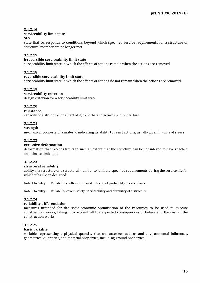
3.1.2.16 serviceability limit state SLS state that corresponds to conditions beyond which specified service requirements for a structure or structural member are no longer met
3.1.2.17 irreversible serviceability limit state serviceability limit state in which the effects of actions remain when the actions are removed
3.1.2.18 reversible serviceability limit state serviceability limit state in which the effects of actions do not remain when the actions are removed
3.1.2.19 serviceability criterion design criterion for a serviceability limit state
3.1.2.20 resistance capacity of a structure, or a part of it, to withstand actions without failure
3.1.2.21 strength mechanical property of a material indicating its ability to resist actions, usually given in units of stress
3.1.2.22 excessive deformation deformation that exceeds limits to such an extent that the structure can be considered to have reached an ultimate limit state
3.1.2.23 structural reliability ability of a structure or a structural member to fulfil the specified requirements during the service life for which it has been designed
Note 1 to entry: Reliability is often expressed in terms of probability of exceedance.
Note 2 to entry: Reliability covers safety, serviceability and durability of a structure.
3.1.2.24 reliability differentiation measures intended for the socio-economic optimisation of the resources to be used to execute construction works, taking into account all the expected consequences of failure and the cost of the construction works
3.1.2.25 basic variable variable representing a physical quantity that characterizes actions and environmental influences, geometrical quantities, and material properties, including ground properties
prEN 1990:2019 (E)
16
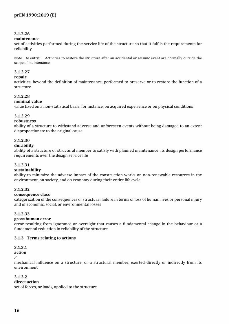
3.1.2.26 maintenance set of activities performed during the service life of the structure so that it fulfils the requirements for reliability
Note 1 to entry: Activities to restore the structure after an accidental or seismic event are normally outside the scope of maintenance.
3.1.2.27 repair activities, beyond the definition of maintenance, performed to preserve or to restore the function of a structure
3.1.2.28 nominal value value fixed on a non-statistical basis; for instance, on acquired experience or on physical conditions
3.1.2.29 robustness ability of a structure to withstand adverse and unforeseen events without being damaged to an extent disproportionate to the original cause
3.1.2.30 durability ability of a structure or structural member to satisfy with planned maintenance, its design performance requirements over the design service life
3.1.2.31 sustainability ability to minimize the adverse impact of the construction works on non-renewable resources in the environment, on society, and on economy during their entire life cycle
3.1.2.32 consequence class categorization of the consequences of structural failure in terms of loss of human lives or personal injury and of economic, social, or environmental losses
3.1.2.33 gross human error error resulting from ignorance or oversight that causes a fundamental change in the behaviour or a fundamental reduction in reliability of the structure
3.1.3 Terms relating to actions
3.1.3.1 action F mechanical influence on a structure, or a structural member, exerted directly or indirectly from its environment
3.1.3.2 direct action set of forces, or loads, applied to the structure

prEN 1990:2019 (E)
17
3.1.3.3 indirect action set of imposed deformations or accelerations caused for example, by temperature changes, moisture variation, uneven settlement or earthquakes
3.1.3.4 effect of action E action-effect resulting effect, on a structural member or on the whole structure, from the application of an action
EXAMPLE Internal forces, moments, stresses, strains, deflections, and rotations.
3.1.3.5 permanent action G action that is likely to act throughout the design service life and for which any variation in magnitude is either small, compared with the mean value, or monotonic; i.e. it either only increases or decreases, until it reaches a limit value
3.1.3.6 variable action Q action that is likely to occur during the design service life for which the variation in magnitude with time is neither negligible nor monotonic
3.1.3.7 accidental action A action, usually of short duration but of significant magnitude, that is unlikely to occur during the design service life
Note 1 to entry: An accidental action can be expected in many cases to cause severe consequences unless appropriate measures are taken.
3.1.3.8 seismic action AE
action that arises due to earthquake
3.1.3.9 geotechnical action action that originates from the self-weight of the ground or groundwater or is transmitted to the structure through the ground or groundwater
3.1.3.10 fixed action action that has a fixed distribution and position over a structure or structural member such as its magnitude and direction are determined unambiguously for the whole structure or structural member when determined at one point on the structure or structural member
3.1.3.11 free action action that can have various arbitrary spatial distributions over the structure
prEN 1990:2019 (E)
18
3.1.3.12 bounded action action that has a limiting value that cannot be exceeded and which is known to a sufficient accuracy
3.1.3.13 single action action that can be assumed to be statistically independent in time and space of any other action acting on the structure
3.1.3.14 static action action that does not cause significant acceleration of the structure or structural members
3.1.3.15 dynamic action action that causes significant acceleration of the structure or structural members
3.1.3.16 quasi-static action dynamic action represented by an equivalent static action in a static model
3.1.3.17 representative value of an action Frep
value of an action used for the verification of a limit state
Note 1 to entry: The representative value can be the characteristic, combination, frequent, or quasi-permanent value (or a nominal value).
3.1.3.18 characteristic value of an action Fk
value of an action chosen, as far as it can be fixed on a statistical basis, to correspond to a prescribed probability of not being exceeded unfavourably during a specified reference period
3.1.3.19 design value of an action Fd
value obtained by multiplying the representative value of an action by a partial factor γF or determined
directly
3.1.3.20 reference period period of time that is used as a basis for statistically assessing extreme realizations of variable actions and possibly for accidental actions
3.1.3.21 combination of actions set of design values of actions used for the verification of the structural reliability for a limit state considering the simultaneous influence of different actions
prEN 1990:2019 (E)
19
3.1.3.22 leading action principal action in a combination
3.1.3.23 accompanying action action that accompanies the leading action in a combination
3.1.3.24 combination value of a variable action Qcomb
value of an accompanying action to be used in the verification of ultimate limit states in persistent or transient design situations and irreversible serviceability limit states
Note 1 to entry: Qcomb can be expressed as a proportion ψ0 of the characteristic value (i.e. Qcomb = ψ0Qk) where
ψ0 ≤ 1.
3.1.3.25 frequent value of a variable action Qfreq
value used in the verification of ultimate limit states involving accidental actions and in the verification of reversible serviceability limit states
Note 1 to entry: Qfreq can be expressed as a proportion ψ1 of the characteristic value (i.e. Qfreq = ψ1Qk), where
ψ1 ≤ 1
3.1.3.26 quasi-permanent value of a variable action Qqper
value used in the verification of ultimate limit states involving accidental or seismic actions; in the verification of reversible serviceability limit states; and in the calculation of long-term effects
Note 1 to entry: Qqper can be expressed as a proportion ψ2 of the characteristic value (i.e. Qqper = ψ2Qk), where
ψ2 ≤ 1.
3.1.4 Terms relating to material and product properties
3.1.4.1 characteristic value of a material or product property Xk
value of a material or product property having a prescribed probability of not being attained in a hypothetical unlimited test series. This value generally corresponds to a specified fractile (superior or inferior) of the assumed statistical distribution of the particular property of the material or product. A nominal value is used as the characteristic value in some circumstances
3.1.4.2 representative value of a material or product property Xrep
value obtained by multiplying the characteristic value of a material or product property by a conversion factor accounting for scale effects, effects of moisture and temperature, effects of ageing of materials, and any other relevant parameters
prEN 1990:2019 (E)
20
3.1.4.3 design value of a material or product property Xd
value obtained by either dividing the inferior representative value of a material or product property by a partial material factor or, when it is more critical, by multiplying the superior representative value by a partial material factor. In special circumstances, it is a value obtained by direct determination
Note 1 to entry: See the other Eurocodes for specific rules.
3.1.5 Terms relating to geometrical data
3.1.5.1 nominal value of a geometrical property anom
value of a geometrical property corresponding to the dimensions specified in the design
Note 1 to entry: Where appropriate, nominal values of geometrical properties may be replaced by a prescribed fractile of their statistical distribution.
3.1.5.2 design value of a geometrical property ad
value of a geometrical property that includes any deviation
Note 1 to entry: Where relevant, it can include possible deviations from nominal value.
3.1.6 Terms relating to structural and geotechnical analysis
3.1.6.1 structural analysis procedure or algorithm for determination of effects of actions in every point of a structure
Note 1 to entry: Structural analyses are sometimes performed at more than one level using different models (e.g. global, member and local analyses).
3.1.6.2 linear behaviour behaviour of a structure or a structural member in which the relationship between actions and their effects is directly proportional
Note 1 to entry: The principle of superposition is applicable to a structure which has a linear behaviour.
3.1.6.3 non-linear behaviour behaviour of a structure or a structural member in which the relationship between actions and their effects is not proportional
3.1.6.4 geometric non-linearity non-linearity caused by changes in geometry from the initial undeformed state
Note 1 to entry: Examples of geometric non-linearity include membranes, cables, flat arches, catenaries, slender columns and beams.
prEN 1990:2019 (E)
21
3.1.6.5 first order theory relationship between actions and effects when the deformations of a structural member or the entire structure do not have significant influence on the equilibrium equation
3.1.6.6 second order theory relationship between actions and effects when the deformations have influence on the equilibrium equation
3.1.6.7 material non-linearity non-linearity caused by a non-linear stress-strain relationship of the material
Note 1 to entry: Examples of material non-linearity include plasticity, cracking in concrete, strain hardening, hysteresis.
3.1.6.8 contact non-linearity non-linearity caused by changes at the contact boundary between structural parts during introduction of actions
Note 1 to entry: Examples of contact non-linearity include friction interface, interface between mortar and masonry elements, soil and footing.
3.1.6.9 non-linearity of the limit state function non-linearity between the resistance and the variables influencing the resistance
Note 1 to entry: This is important for the application of partial factors.
3.1.6.10 stress history stress variation during time
3.2 Symbols and abbreviations
For the purposes of this European Standard, the following symbols apply.
NOTE The notation used is based on ISO 3898:1987.
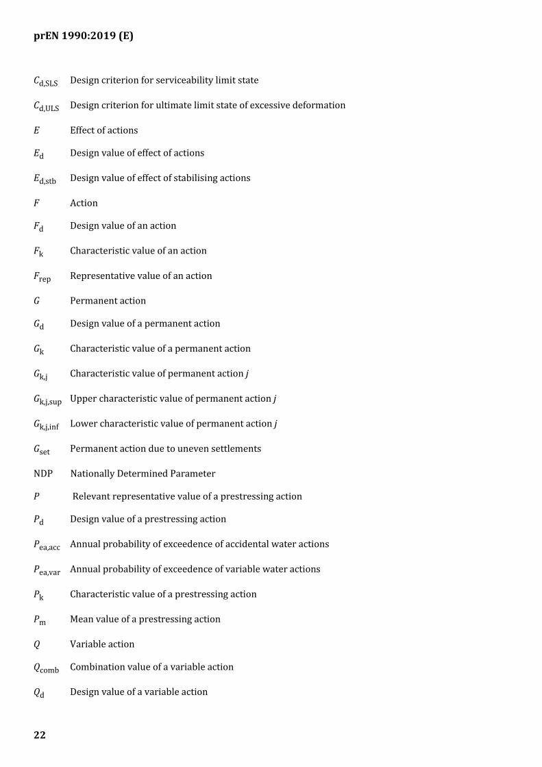
3.2.1 Latin upper-case letters
A Accidental action
Ad Design value of an accidental action
AE Seismic action
AEd Design value of seismic action
AEd,ULS Design value of seismic action in an ultimate limit state
AEd,SLS Design value of seismic action in a serviceability limit state
prEN 1990:2019 (E)
22
Cd,SLS Design criterion for serviceability limit state
Cd,ULS Design criterion for ultimate limit state of excessive deformation
E Effect of actions
Ed Design value of effect of actions
Ed,stb Design value of effect of stabilising actions
F Action
Fd Design value of an action
Fk Characteristic value of an action
Frep Representative value of an action
G Permanent action
Gd Design value of a permanent action
Gk Characteristic value of a permanent action
Gk,j Characteristic value of permanent action j
Gk,j,sup Upper characteristic value of permanent action j
Gk,j,inf Lower characteristic value of permanent action j
Gset Permanent action due to uneven settlements
NDP Nationally Determined Parameter
P Relevant representative value of a prestressing action
Pd Design value of a prestressing action
Pea,acc Annual probability of exceedence of accidental water actions
Pea,var Annual probability of exceedence of variable water actions
Pk Characteristic value of a prestressing action
Pm Mean value of a prestressing action
Q Variable action
Qcomb Combination value of a variable action
Qd Design value of a variable action
prEN 1990:2019 (E)
23
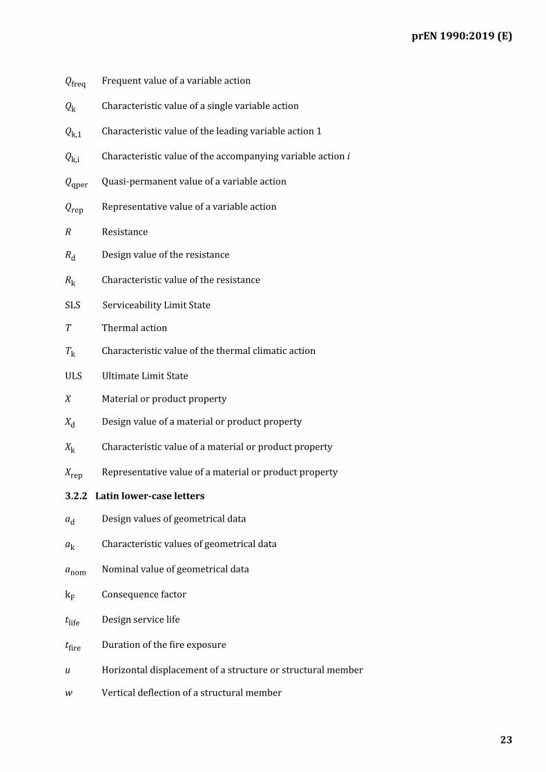
Qfreq Frequent value of a variable action
Qk Characteristic value of a single variable action
Qk,1 Characteristic value of the leading variable action 1
Qk,i Characteristic value of the accompanying variable action i
Qqper Quasi-permanent value of a variable action
Qrep Representative value of a variable action
R Resistance
Rd Design value of the resistance
Rk Characteristic value of the resistance
SLS Serviceability Limit State
T Thermal action
Tk Characteristic value of the thermal climatic action
ULS Ultimate Limit State
X Material or product property
Xd Design value of a material or product property
Xk Characteristic value of a material or product property
Xrep Representative value of a material or product property
3.2.2 Latin lower-case letters
ad Design values of geometrical data
ak Characteristic values of geometrical data
anom Nominal value of geometrical data
kF Consequence factor
tlife Design service life
tfire Duration of the fire exposure
u Horizontal displacement of a structure or structural member
w Vertical deflection of a structural member

prEN 1990:2019 (E)
24
3.2.3 Greek upper-case letters
Δa Change made to nominal geometrical data for particular design purposes, e.g. assessment of
effects of geometrical imperfections
3.2.4 Greek lower-case letters
γ Partial factor (safety or serviceability)
γbt Maximum peak value of bridge deck acceleration for ballasted track
γdf Maximum peak value of bridge deck acceleration for direct fastened track
γGset Partial factor for permanent actions due to settlements, also accounting for model uncertainties
γf Partial factor for actions, which takes account of the possibility of unfavourable deviations of the
action values from the representative values
γF Partial factor for actions, also accounting for model uncertainties and dimensional variations
γG Partial factor for permanent actions, also accounting for model uncertainties and dimensional
variations
γG,j Partial factor for permanent action j
γG,j,sup Partial factor for permanent action j in calculating upper/lower design values
γG,j,inf Partial factor for permanent action j in calculating upper/lower design values
γm Partial factor for a material property
γM Partial factor for a material property, also accounting for model uncertainties and dimensional
variations
γP Partial factor for prestressing actions (see other relevant Eurocodes)
γQ Partial factor for variable actions, also accounting for model uncertainties and dimensional
variations
γQ,i Partial factor for variable action i
γRd Partial factor associated with the uncertainty of the resistance model
γSd Partial factor associated with the uncertainty of the action and/or action effect model
η Conversion factor
ξ Reduction factor
ψ Combination factor applied to a characteristic variable action
prEN 1990:2019 (E)
25
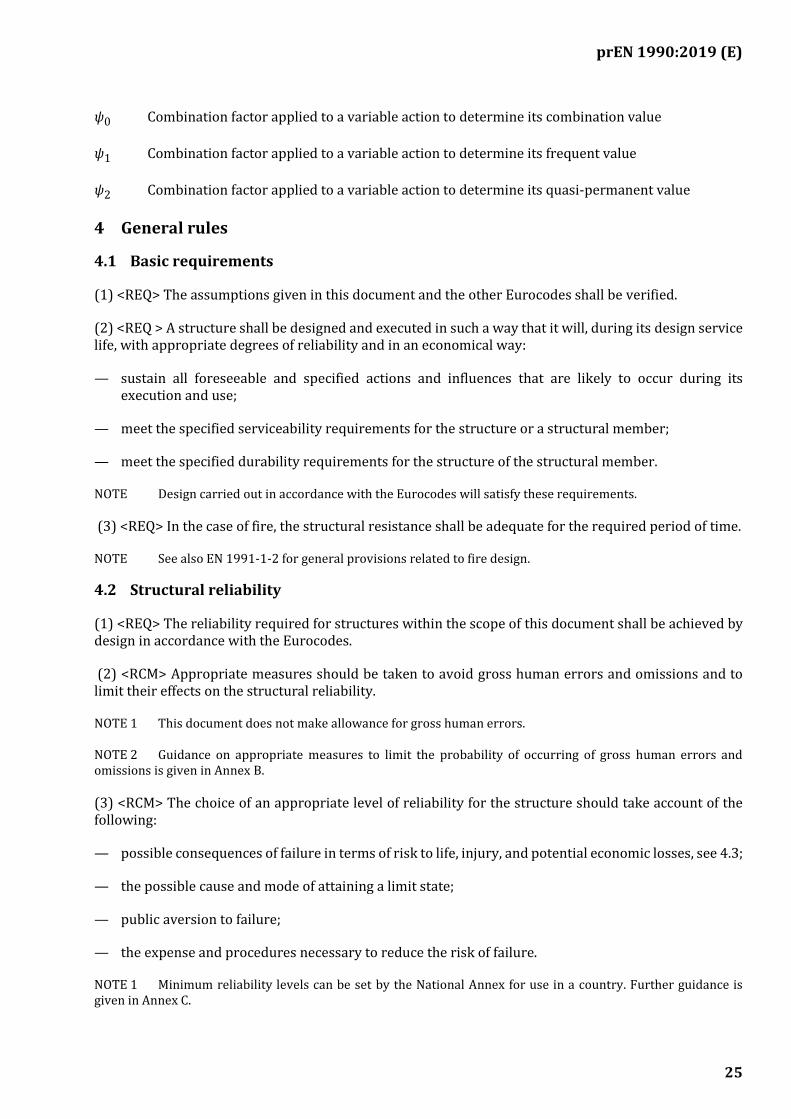
ψ0 Combination factor applied to a variable action to determine its combination value
ψ1 Combination factor applied to a variable action to determine its frequent value
ψ2 Combination factor applied to a variable action to determine its quasi-permanent value
4 General rules
4.1 Basic requirements
(1) <REQ> The assumptions given in this document and the other Eurocodes shall be verified.
(2) <REQ > A structure shall be designed and executed in such a way that it will, during its design service life, with appropriate degrees of reliability and in an economical way:
— sustain all foreseeable and specified actions and influences that are likely to occur during its execution and use;
— meet the specified serviceability requirements for the structure or a structural member;
— meet the specified durability requirements for the structure of the structural member.
NOTE Design carried out in accordance with the Eurocodes will satisfy these requirements.
(3) <REQ> In the case of fire, the structural resistance shall be adequate for the required period of time.
NOTE See also EN 1991-1-2 for general provisions related to fire design.
4.2 Structural reliability
(1) <REQ> The reliability required for structures within the scope of this document shall be achieved by design in accordance with the Eurocodes.
(2) <RCM> Appropriate measures should be taken to avoid gross human errors and omissions and to limit their effects on the structural reliability.
NOTE 1 This document does not make allowance for gross human errors.
NOTE 2 Guidance on appropriate measures to limit the probability of occurring of gross human errors and omissions is given in Annex B.
(3) <RCM> The choice of an appropriate level of reliability for the structure should take account of the following:
— possible consequences of failure in terms of risk to life, injury, and potential economic losses, see 4.3;
— the possible cause and mode of attaining a limit state;
— public aversion to failure;
— the expense and procedures necessary to reduce the risk of failure.
NOTE 1 Minimum reliability levels can be set by the National Annex for use in a country. Further guidance is given in Annex C.
prEN 1990:2019 (E)
26
NOTE 2 Different levels of reliability are commonly adopted for limit states relating to structural failure, serviceability, and durability.
NOTE 3 Levels of reliability for structural failure and serviceability are achieved by:
— appropriate representation of the basic variables, see Clause 6;
— accuracy of the mechanical models used and interpretation of their results;
— prevention of errors in design and execution of the structure, including gross human errors, see also Annex B;
— adequate inspection and maintenance according to procedures specified in the project documentation.
4.3 Consequences of failure
(1) <REQ> The consequences of failure of the structure or a structural member shall be classified into one of the five following consequence classes:
— CC4 – highest consequence;
— CC3 – higher consequence;
— CC2 – normal consequence;
— CC1 – lower consequence;
— CC0 – lowest consequence.
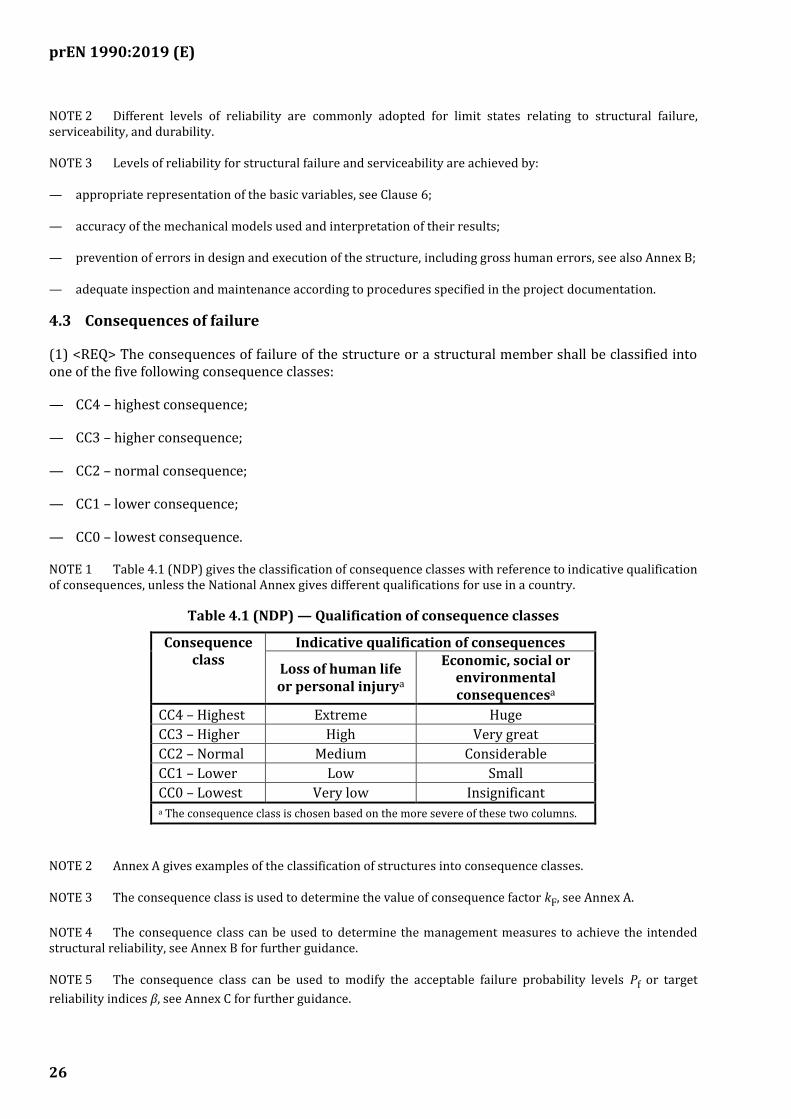
NOTE 1 Table 4.1 (NDP) gives the classification of consequence classes with reference to indicative qualification of consequences, unless the National Annex gives different qualifications for use in a country.
Table 4.1 (NDP) — Qualification of consequence classes
Consequence class
Indicative qualification of consequences
Loss of human life or personal injurya
Economic, social or environmental consequencesa
CC4 – Highest Extreme Huge
CC3 – Higher High Very great
CC2 – Normal Medium Considerable
CC1 – Lower Low Small
CC0 – Lowest Very low Insignificant a The consequence class is chosen based on the more severe of these two columns.
NOTE 2 Annex A gives examples of the classification of structures into consequence classes.
NOTE 3 The consequence class is used to determine the value of consequence factor kF, see Annex A.
NOTE 4 The consequence class can be used to determine the management measures to achieve the intended structural reliability, see Annex B for further guidance.
NOTE 5 The consequence class can be used to modify the acceptable failure probability levels Pf or target
reliability indices β, see Annex C for further guidance.
prEN 1990:2019 (E)
27
NOTE 6 The consequence class can be used in the direct assessment of the design values for ULS verifications, see Annex D for further guidance.
NOTE 7 The consequence class can be used to choose design methods for enhancing robustness, see Annex E for further guidance.
(2) <POS> Consequence classes CC1 to CC3 can be divided into upper and lower sub-classes in other Eurocodes.
NOTE 1 The provisions in Eurocodes cover design rules for structures classified as CC1 to CC3.
NOTE 2 The provisions in the Eurocodes do not entirely cover design rules needed for structures classified as CC4. For these structures additional provisions to those given in the Eurocodes can be needed.
(3) <PER> For consequence class CC0, either the Eurocodes or alternative provisions may be used.
(4) <PER> Elements other than structural may be classified as CC0.
4.4 Robustness
(1) <RCM> A structure should be designed to have an adequate level of robustness so that, during its design service life it will not be damaged by adverse and unforeseen events, such as the failure or collapse of a structural member or part of a structure, to an extent disproportionate to the original cause.
NOTE 1 Progressive collapse is an example of a damage that is disproportionate to the original cause.
NOTE 2 For most structures, design in accordance with the Eurocodes provides an adequate level of robustness without the need for any additional design measures to enhance structural robustness.
(2) <RCM> Design measures to enhance structural robustness should be applied when specified by the relevant authority or agreed for a specific project by the relevant parties.
NOTE Guidance on additional design measures to enhance structural robustness for buildings and bridges is given in Annex E, unless the National Annex gives other guidance for use in a country.
4.5 Design service life
(1) <RCM> The design service life Tlife of the structure should be specified.
NOTE Values of Tlife are given in Annex A for different categories of structures.
(2) <RCM> The design service life should be used to determine the time-dependent performance of the structure.
NOTE Examples of time-dependent performance include durability, fatigue, and deformation due to consolidation of the ground.
(3) <RCM> Structures or parts of structures that can be dismantled in order to be re-used should not be classified as temporary structures.
(4) <PER> A reduced design service life may be used for the verification of fatigue and durability of replaceable structures and parts, provided that the replacement is explicitly taken into account in the design.
NOTE See 4.6 for the verification of durability and 8.3.5.4 for the verification of fatigue.
prEN 1990:2019 (E)
28
4.6 Durability
(1) <REQ> The structure shall be designed such that any deterioration over its design service life does not impair its intended performance, having due regard to its exposure to the environment and its anticipated level of maintenance.
(2) <RCM> To achieve adequate durability, the structural design should take into account:
— the structure's intended or foreseeable use;
— any required design criteria;
— expected environmental conditions;
— composition, properties and performance of structural materials and products, both on their own and in combination with other materials;
— properties of the ground;
— the choice of structure, the shape of structural members, and structural detailing;
— the quality of workmanship and level of control on site;
— any protective measures that are implemented;
— any intended maintenance during the structure's design service life.
NOTE The other Eurocodes specify appropriate measures to increase the durability of the structure.
(3) <REQ> The environmental conditions shall be identified during design so that their impact on durability can be assessed and adequate provisions can be made for protection of the materials used in the structure.
(4) <PER> The degree of any deterioration affecting the capacity of a structure or a structural elment may be estimated using calculation, experimental investigation, experience from earlier constructions, or a combination of these methods.
4.7 Sustainability
(1) <RCM> The structure should be designed to limit its adverse impact on non-renewable environmental resources, on society, and on economy during its entire life cycle, as specified by the relevant authority or agreed for a specific project by the relevant parties.
NOTE The adverse impact of a structure on its environment, on society, and on economy can be minimized by appropriate choice of construction process, environmentally compatible building materials, including their manufacture, design solutions, durability, and recyclability.
4.8 Quality Management
(1) <RCM> Appropriate quality management measures should be implemented to provide a structure that corresponds to the design requirements and assumptions.
prEN 1990:2019 (E)
29
(2) <RCM> The following quality management measures should be implemented:
— organizational procedures in design, execution, use, and maintenance;
— controls at the stages of design, detailing, execution, use, and maintenance.
NOTE See Annex B and the other Eurocodes for guidance on appropriate quality management measures.
5 Principles of limit state design
5.1 General
(1) <REQ> A distinction shall be made between ultimate and serviceability limit states.
(2) <PER> Verification of a particular limit state may be omitted if the verification of another limit state demonstrates that the former will not be exceeded.
(3) <REQ> Limit states shall be verified for all relevant design situations.
(4) <RCM> Limit states that involve the time-dependent performance of the structure should be verified taking into account its design service life.
NOTE Indicative design service lives are given in Table 4.2 (NDP).
5.2 Design situations
(1) <REQ> Design situations shall be selected appropriately for the conditions under which the structure has to meet its requirements.
(2) <REQ> Design situations shall be sufficiently severe and varied so that they encompass all conditions that can reasonably be foreseen to occur during execution and use of the structure.
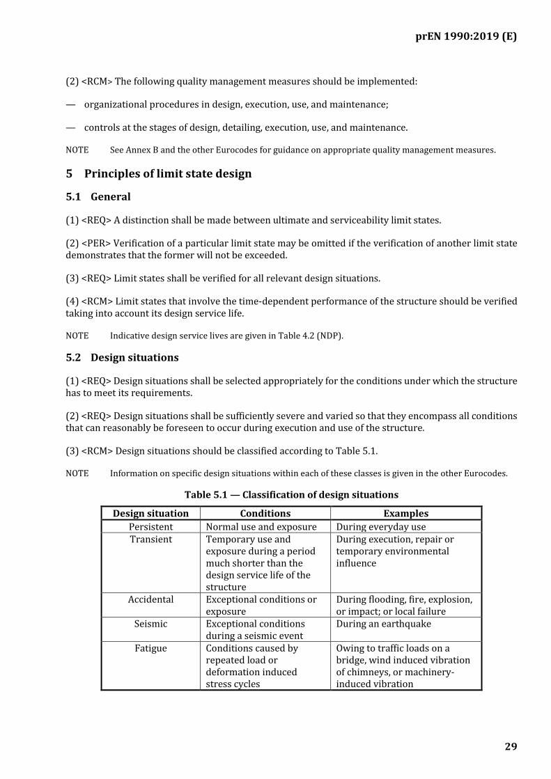
(3) <RCM> Design situations should be classified according to Table 5.1.
NOTE Information on specific design situations within each of these classes is given in the other Eurocodes.
Table 5.1 — Classification of design situations
Design situation Conditions Examples
Persistent Normal use and exposure During everyday use Transient Temporary use and
exposure during a period much shorter than the design service life of the structure
During execution, repair or temporary environmental influence
Accidental Exceptional conditions or exposure
During flooding, fire, explosion, or impact; or local failure
Seismic Exceptional conditions during a seismic event
During an earthquake
Fatigue Conditions caused by repeated load or deformation induced stress cycles
Owing to traffic loads on a bridge, wind induced vibration of chimneys, or machinery-induced vibration
prEN 1990:2019 (E)
30
5.3 Ultimate limit states (ULS)
(1) <REQ> Limit states that concern the safety of the structure to prevent:
— human losses or injury to people;
— unacceptable economic or environmental losses;
shall be classified as ultimate limit states (ULS).
(2) <PER> States prior to structural collapse may be treated as ultimate limit states.
NOTE For example when the structural response is ductile and collapse is difficult to define, it can be convenient to treat a state prior to collapse as the ultimate limit state.
(3) <REQ> The following ultimate limit states shall be verified, if relevant:
— failure of the structure or the ground, or any part of them including supports and foundations, by rupture, excessive deformation, transformation into a mechanism, or buckling;
— loss of static equilibrium of the structure or any part of it;
— failure of the ground by hydraulic heave, internal erosion, or piping caused by excessive hydraulic gradients;
— failure caused by fatigue;
— failure caused by vibration;
— failure caused by other time-dependent effects.
NOTE 1 Details of ultimate limit states caused by fatigue are given in the other Eurocodes.
NOTE 2 Details of ultimate limit states caused by hydraulic gradients are given in EN 1997.
NOTE 3 Loss of static equilibrium includes uplift by water pressure (buoyancy) or other vertical actions.
(4) <RCM> When verifying loss of static equilibrium, variations in the magnitude or spatial distribution of permanent actions from a single-source should be considered.
NOTE The term 'single-source' is explained in 6.1.1.
5.4 Serviceability limit states (SLS)
(1) <REQ> Limit states that concern:
— the functioning of the structure or structural members under normal use;
— the comfort of people;
— the appearance of the construction works;
shall be classified as serviceability limit states (SLS).
prEN 1990:2019 (E)
31
NOTE The term 'appearance' here is concerned with criteria such as large deflections or extensive cracking, rather than aesthetics.
(2) <REQ> A distinction shall be made between reversible and irreversible serviceability limit states.
(3) <RCM> The verification of serviceability limit states should be based on criteria concerning the following:
— deformations that adversely affect the appearance, the comfort of users, or the functioning of the structure (including the functioning of machines or services);
— deformations that cause damage to finishes or elements other than structural;
— vibrations that cause discomfort to people or limit the functional effectiveness of the structure;
— damage that is likely to adversely affect the appearance, durability, or functioning of the structure.
NOTE 1 Elements 'other than structural' refers to partition walls, false ceilings, etc.
NOTE 2 Additional provisions related to serviceability criteria are given in the other Eurocodes.
(4) <RCM> Serviceability requirements should be specified individually for each project.
NOTE Serviceability criteria for some serviceability limit states are given in Annex A.
5.5 Structural and load models
(1) <REQ> Limit states shall be verified using appropriate structural and load models.
(2) <REQ> The structural models and load models that are used to verify limit states shall be based on design values for:
— actions;
— material and product properties;
— geometrical data.
(3) <REQ> All relevant design situations shall be identified.
(4) <REQ> The structure shall be verified for all critical load cases in each relevant design situation.
(5) <RCM> Design values for the basic variables given in (2) should be obtained using the partial factor method, given in Clause 8.
(6) <PER> As an alternative to (5), design based on probabilistic methods may be used when authorized by the relevant authority or agreed for a specific project by the relevant parties.
NOTE Further guidance on probabilistic methods is given in Annex C.
prEN 1990:2019 (E)
32
6 Basic variables
6.1 Actions and environmental influences
6.1.1 Classification of actions
(1) <REQ> Actions F shall be classified by their variation in time as follows:
— permanent (G); or
— variable (Q); or
— accidental (A); or
— seismic (AE).
(2) <PER> Climatic actions, such as wind and snow actions, may be classified as either variable or accidental, depending on site location.
NOTE See EN 1991.
(3) <PER> Actions may also be classified by their:
— origin, as direct or indirect; or
— spatial variation, as fixed or free; or
— nature and/or the structural response, as static or dynamic.
(4) <PER> Actions that, owing to physical reasons, induce effects that are strongly correlated with one another, even when they originate in, or act on, different parts of the structure, or originate from different materials, may be treated as an action arising from a single source.
NOTE 1 This rule is commonly known as the ‘single-source principle’.
NOTE 2 The single-source principle typically applies to the self-weight of the structure or the ground and of components made of different materials as well as for water pressures acting on both sides of a structure with flow passing around or underneath.
(5) <PER> Climatic actions from wind, snow, temperature or water that act on different parts of a structure may be considered to come from a single-source.
6.1.2 Representative values of actions
6.1.2.1 General
(1) <RCM> The principal representative value of an action Frep should be its characteristic value Fk.
NOTE Representative values are not defined for accidental and seismic actions, see Clause 8 for the definition of design values.
(2) <PER> For variable actions (see 6.1.2.3) and actions inducing fatigue (see 6.1.3.3), other representative values may be chosen, depending on the limit state being verified.
prEN 1990:2019 (E)
33
(3) <REQ> The characteristic value of an action shall be chosen according to the methods given in EN 1991, EN 1997, and EN 1998.
NOTE The characteristic value of an action Fk can be:
— a mean value; or
— an upper or lower value; or
— a nominal value.
6.1.2.2 Permanent actions
(1) <REQ> The representative value Grep of a permanent action G shall be taken as its characteristic value
Gk.
(2) <RCM> Provided its coefficient of variation is small, a permanent action G should be represented by a single characteristic value Gk.
(3) <PER> For most structural members, the coefficient of variation of G may be considered small if:
— it is not greater than 5 %, when verifying limit states involving overturning or uplift; or
— it is not greater than 10 %, otherwise.
NOTE See EN 1997 for the assessment of the coefficient of variation of permanent actions from the ground.
(4) <PER> If a single characteristic value of Gk is used, then its value may be taken as the mean value of
G.
(5) <PER> If the self-weight of the structure or structural member is represented by a single characteristic value, it may be calculated from the product of the nominal dimensions of the structure or structural member and its characteristic weight density.
NOTE Values of characteristic mass densities for various materials are given in EN 1991-1-1.
(6) <RCM> If the uncertainty in G is not small, or if the structure is sensitive to variations in its value or spatial distribution, then the permanent action G should be represented by upper and lower characteristic values Gk,sup and Gk,inf respectively.
NOTE Permanent actions are usually assumed to be normally distributed.
(7) <RCM> For materials other than the ground, the upper (or "superior") characteristic value Gk,sup
should be selected as the 95 % fractile and the lower (or "inferior") characteristic value Gk,inf as the 5 %
fractile of the statistical distribution of G.
NOTE 1 For the ground, see EN 1997 for the specification of Gk,sup and Gk,inf.
NOTE 2 See 6.1.3.2 for the specification of permanent water actions.
prEN 1990:2019 (E)
34
6.1.2.3 Variable actions
(1) <REQ> The representative value Qrep of a variable action Q shall be taken as one of the following,
depending on the limit state being verified:
— its characteristic value Qk ; or
— its combination value Qcomb ; or
— its frequent value Qfreq ; or
— its quasi-permanent value Qqper.
(2) <REQ> The characteristic value of a variable action Qk shall correspond to one of the following:
— an upper value with an intended probability of not being exceeded during a specific reference period; or
— a lower value with an intended probability of being exceeded during the same reference period; or
— when the statistical distribution of Q is not known, a nominal value.
NOTE 1 Upper and lower values and nominal values are given in the various Parts of EN 1991.
NOTE 2 The characteristic value of a variable climatic action is based upon a 2 % probability that its time-varying part is exceeded during a one-year reference period. This is equivalent to a mean return period of 50 years.
NOTE 3 All coefficients or models, to derive characteristic values of variable actions are chosen so that the annual probability of exceedance of the calculated characteristic value does not exceed the annual probability of exceedance of the time-varying part of the variable action.
(3) <RCM> The combination, frequent and quasi-permanent values should be determined by multiplying the characteristic values Qk by combination factors ψ0, ψ1 and ψ2 as given in Formulae (6.1) to (6.3):
𝑄comb = 𝜓0𝑄k (6.1)
𝑄freq = 𝜓1𝑄k (6.2)
𝑄qper = 𝜓2𝑄k (6.3)
NOTE 1 The values of ψ0, ψ1, and ψ2 are given in Annex A.
NOTE 2 The characteristic value is used in the verification of ultimate limit states, see 8.3.
NOTE 3 The combination value is used in the verification of ultimate limit states and irreversible serviceability limit states.
NOTE 4 The frequent value is used in the verification of ultimate limit states involving accidental actions and in the verification of reversible serviceability limit states. For buildings, the frequent value is chosen so that the the time it is exceeded is 0,01 of the reference period. For road traffic loads on bridges, the frequent values is assessed on the basis of a return period of one week.
prEN 1990:2019 (E)
35
NOTE 5 The quasi-permanent value is used in the verification of ultimate limit states involving accidental or seismic actions; in the verification of reversible serviceability limit states; and in the calculation of long-term effects. For loads on building floors, the quasi-permanent value is chosen so that the the time it is exceeded is 0,50 of the reference period. It can alternatively be determined as the value averaged over a chosen period of time.
(4) <PER> For some specific types of actions, particularly water actions, representative values may be defined directly, without the use of combination factors.
NOTE See 6.1.3.2 for the specification of variable water actions.
6.1.3 Specific types of action
6.1.3.1 Prestress
(1) <RCM> Prestressing forces P that are caused by the controlled application of forces or deformations to a structure should be classified as permanent actions.
NOTE Prestressing forces acting on a structure can arise from prestressing tendons, imposed deformations at supports, etc.
(2) <RCM> A prestressing force P should be represented by its upper or lower characteristic value, Pk,sup
or Pk,inf respectively.
(3) <PER> For ultimate limit states, if allowed by the other Eurocodes, a prestressing force P may be represented by a single characteristic value Pk.
6.1.3.2 Water actions
(1) <RCM> Actions that arise from water should be classified as permanent, variable, or accidental.
NOTE This paragraph 6.1.3.2 is not applicable to water actions induced by currents and waves. For these actions see Annex A.6 and EN1991-1-8.
(2) <RCM> When a water action is classified as permanent, as defined in 6.1.2.2, its representative value Gw;rep should be selected as either:
— a single characteristic value Gw,k taken as the mean value of Gw; or
— the more onerous of its characteristic upper and lower values Gw,k;sup or Gw,k;inf ; or
— a nominal value.
NOTE Further information can be found in Annex A, EN 1991 and EN 1997.
(3) <RCM> When a water action is classified as variable, it should be represented by two components:
— a permanent component Gw;rep taken as the mean of Gw;
— a variable component Qw;rep equal to the representative value of the variation in water action.
(4) <RCM> The representative value Qw,rep should be selected in line with the definitions of
characteristic, frequent and quasi-permanent values in 6.1.2.3(1).
prEN 1990:2019 (E)
36
NOTE 1 The value of Qw;k is based on an annual probability of exceedance of 2 % (corresponding to a return
period of 50 years), unless the National Annex gives a different value for use in a country.
NOTE 2 The value of Qw;comb is based on an annual probability of exceedance of 5 % (corresponding to a return
period of 20 years), unless the National Annex gives a different value for use in a country.
NOTE 3 The value of Qw;freq is chosen so that the time it is exceeded is 0,01 of the reference period, unless the
National Annex gives a different value for use in a country.
NOTE 4 The value of Qw;qper is chosen so that the time it is exceeded is 0,50 of the reference period, unless the
National Annex gives a different value for use in a country.
NOTE 5 For seismic verifications involving water actions, see EN 1998-5.
(5) <PER> The values of Qw,k and Qw,comb may alternatively be determined taking account of any physical
limitations that affect the actions.
NOTE Physical limitation can include, for example, the top of a retaining wall or the presence of drains.
(6) <RCM> When a water action is classified as accidental, it should be represented by a single value Aw;rep equal to the representative value of the water action.
NOTE The value of Aw;rep is based on an annual probability of exceedance of 0.1 % (corresponding to a return
period of 1000 years), unless the National Annex gives a different value for use in a country.
6.1.3.3 Fatigue actions
(1) <REQ> Models for fatigue actions shall be defined for the action effect spectrum and the expected number of cycles during the design life.
NOTE The action effect spectrum depends on the type of structure.
(2) <RCM> When relevant, the stress variation during time (stress history) should take account of any interaction between the action and the structure.
(3) <PER> The fatigue load models in EN 1991 may be used for fatigue verifications.
NOTE The fatigue load models in EN 1991 include the dynamic action effect, either:
— implicitly in the equivalent and frequent fatigue load values; or
— explicitly by applying dynamic enhancement amplification factors to fatigue loads.
(4) <RCM> For structures outside the field of application of the models given in EN 1991, fatigue actions should be defined from the evaluation of measurements or ad hoc studies devoted to determine the expected action effect spectra.
(5) <PER> Models for fatigue actions may be based on the evaluation of structural response to load fluctuations, expressed in terms of frequent or equivalent fatigue load models.
NOTE 1 The frequent fatigue load models are intended to assess unlimited fatigue life. These models are defined only for materials for which a a constant amplitude fatigue limit is given in the relevant Eurocodes
NOTE 2 The equivalent fatigue load models are intended to produce the same fatigue damage induced by the action spectra, considering relevant S-N curves.
prEN 1990:2019 (E)
37
(6) <RCM> Stress ranges due to high-cycle fatigue should be derived by an appropriate cycle counting method.
(7) <PER> Stress ranges due to high-cycle fatigue may be derived by either the rain-flow or reservoir counting method.
NOTE 1 Rain-flow and reservoir counting methods are equivalent.
NOTE 2 See Annex F.
(8) <RCM> When fatigue damage depends on the mean stress of the cycle, the assessment procedure should be consistent with this dependency.
6.1.3.4 Geotechnical actions
(1) <REQ> Geotechnical actions shall be assessed in accordance with EN 1997-1.
6.1.4 Environmental influences
(1) <RCM> The environmental influences that could affect the durability of the structure should be considered in the choice of structural materials, their specification, the structural concept, and detailed design.
NOTE The other Eurocodes give relevant measures for considering environmental influences.
6.2 Material and product properties
(1) <RCM> Properties of materials and products should be represented by characteristic values.
NOTE Materials in this sub-clause include the ground.
(2) <RCM> Unless otherwise stated in the Eurocodes, when the verification of a limit state is sensitive to the variability of a material property, its characteristic value should be defined as:
— the 5 % fractile value where a low value of material or product property is unfavourable; or
— the 95 % fractile value where a high value of material or product property is unfavourable.
NOTE See EN 1997 for the specification of characteristic values of ground properties.
(3) <RCM> When the verification of a limit state is insensitive to the variability of a material property, its characteristic value should be defined as the mean value, unless otherwise stated in the other Eurocodes.
(4) <RCM> Material properties should be determined from standard tests performed under specified conditions.
(5) <REQ> A conversion factor shall be applied when it is necessary to convert test results into values that represent the behaviour of the material or product in the structure or ground.
NOTE See Annex D and the other Eurocodes for values of the conversion factor, if needed.
(6) <PER> When insufficient statistical data is available to establish the characteristic value of a material or product property, the characteristic value may be taken as a nominal value.
prEN 1990:2019 (E)
38
(7) <RCM> When material or product properties are not specified in the Eurocodes, their values should be chosen to achieve a level of structural reliability no less than that specified in the Eurocodes.
NOTE See Annex C for guidance on structural reliability.
6.3 Geometrical parameters
(1) <RCM> Unless the design of the structure is sensitive to deviations of a geometrical parameter, that parameter should be represented by its nominal value.
(2) <RCM> If the design of the structure is sensitive to deviations of a geometrical parameter, corresponding geometrical imperfections defined in the other Eurocodes should be taken into account.
(3) <PER> When there is sufficient data, the characteristic value of a geometrical parameter may be determined from its statistical distribution and used instead of a nominal value.
(4) <REQ> Connected parts that are made from different materials shall be physically compatible.
(5) <PER> For geotechnical design, geometrical data that affect the mechanical behaviour of the ground should be considered when determining ground properties, as specified in EN 1997.
NOTE For example, the spacing and orientation of discontinuities are taken into account when selecting the characteristic material properties of rock.
7 Structural analysis and design assisted by testing
7.1 Structural modelling
7.1.1 General
(1) <REQ> Calculations shall be carried out using appropriate structural models involving relevant variables.
NOTE Such calculations can be used to model potential failure modes, predict ultimate capacity, or model deformations (provided the results can be verified with satisfactory accuracy).
(2) <REQ> Structural models shall be based on established engineering theory and practice.
7.1.2 Static actions
(1) <REQ> The modelling of static actions shall be based on an appropriate choice of the force-deformation relationships of the members and their connections and between members and the ground.
(2) <REQ> Effects of displacements and deformations shall be taken into account in ultimate limit state verifications if they result in a significant increase of the effects of actions.
NOTE Particular methods for dealing with effects of deformations are given in the other Eurocodes.
(3) <RCM> Indirect actions should be introduced into the analysis as follows:
— in linear elastic analysis, directly or as equivalent forces (using appropriate modular ratios where relevant); or
— in non-linear analysis, directly as imposed deformations.
prEN 1990:2019 (E)
39
7.1.3 Dynamic actions
(1) <RCM> When time-dependent actions cause significant acceleration of the structure, dynamic analysis of the system should be performed.
NOTE 1 Guidance on the need for dynamic analysis is given in EN 1991.
NOTE 2 For seismic actions, see EN 1998.
(2) <PER> Dynamic actions may be expressed by time histories or content in the frequency domain.
(3) <PER> Where relevant, action effects may be defined by a modal analysis.
(4) <PER> For structures that have regular geometry, stiffness, and mass distribution, an explicit modal analysis may be replaced by an analysis with equivalent static actions provided.
NOTE Examples of relevant actions are wind induced vibrations or seismic actions.
(5) <PER> When it is appropriate to consider a dynamic action as quasi-static, its dynamic part may be considered either by including it in the quasi-static value or by applying an equivalent dynamic amplification factor to the static action.
NOTE 1 Quasi-static actions are defined in EN 1991.
NOTE 2 For limitations to verifications by the partial factor method, see 8.2.
(6) <RCM> When dynamic action causes vibrations of magnitude or frequency that could exceed serviceability requirements, a specific serviceability limit state verification should be carried out.
NOTE Guidance for assessing these limits is given in Annex A and the other Eurocodes.
7.1.4 Actions inducing fatigue
(1) <RCM> The parameters needed for fatigue verification should be consistent with the S-N curve used.
(2) <RCM> Stress history should be determined in terms of nominal stresses, hot spot stresses or effective notch stresses at locations of stress concentrations.
7.1.5 Fire design
(1) <REQ> Structural fire design analysis shall be based on design fire scenarios and shall consider models for the temperature evolution within the structure as well as models for the mechanical behaviour of the structure exposed to fire.
NOTE See EN 1991-1-2 for guidance on selecting design fire scenarios.
(2) <REQ> The behaviour of a structure exposed to fire shall be assessed by taking into account the accompanying actions and either:
— nominal fire exposure; or
— physically-based fire exposure.
(3) <RCM> The required performance of a structure exposed to fire should be verified by either:
prEN 1990:2019 (E)
40
— global analysis; or
— analysis of parts of the structure; or
— member analysis by means of one or more of the following design methods:
— tabulated design data;
— simplified design methods;
— advanced design methods.
(4) <PER> As an alternative to design by calculation, fire resistance assessment may be based on the results of fire tests or on fire tests in combination with calculations.
(5) <RCM> In case of design by calculation, the behaviour of the structure exposed to fire shall be assessed according to relevant clauses in the other Eurocodes concerning thermal and mechanical models for analysis.
(6) <RCM> The mechanical models of the structure exposed to fire should take account of both temperature-dependant mechanical properties and non-linear behaviour, where relevant.
(7) <RCM> With physically-based fire exposure, the behaviour of the structure should be assessed for a minimum time period Tfire.
NOTE The value of Tfire is the full duration of the fire (including the cooling phase) unless the National Annex
or national regulations give a different value for use in a country.
7.2 Analysis
7.2.1 Linear Analysis
(1) <PER> Linear analysis may be used when the relation between stresses and strains is linear and deformations do not influence the equilibrium of the structure.
NOTE The law of superposition is valid for linear analysis.
(2) <PER> Linear analysis may also be used as a simplification of real behaviour of the structure, as specified in the other Eurocodes.
7.2.2 Non-linear analysis
(1) <RCM> Non-linear analysis should be used when the behaviour of the structure or members has a significant influence on forces in and deformations of the structure.
NOTE The law of superposition is not valid for non-linear analysis.
(2) <RCM> Non-linear analysis should take into account the relevant type of non-linearity.
NOTE Non-linearity can occur in loading, material behaviour, and geometry.
(3) <RCM> Numerical models that describe material properties and their interaction should capture all significant and relevant aspects of mechanical behaviour for the specific problem being considered.
prEN 1990:2019 (E)
41
(4) <RCM> Non-linear numerical models should be validated by tests, to establish whether the numerical model correctly reproduces the necessary physical phenomena.
NOTE Depending on the physical phenomena being investigated, validation tests can include basic material tests, physical reference tests, and mesh sensitivity tests.
(5) <RCM> A sensitivity study should be carried out when a non-linear limit state function is used or, when no explicit limit state function is given, to determine the most sensitive input parameter and how to apply the partial factors given in the Eurocodes.
7.3 Design assisted by testing
(1) <PER> Physical or numerical testing may be used to determine parameters for use in design.
(2) <PER> Testing may be used to determine the performance of a structure or structural member as specified by the relevant authority or agreed for a specific project by the relevant parties.
NOTE Testing is carried out, for example, in the following circumstances:
— if adequate calculation models are not available;
— to confirm by control checks assumptions made in the design;
— to define S-N curves;
— to determine shape factors for snow load;
— to determine pressure or force coefficients for wind actions;
— if a large number of similar components are to be used.
(3) <REQ> Design assisted by test results shall achieve the level of reliability required for the relevant design situation, taking into account the statistical uncertainty due to a limited number of test results and the uncertainty of the model.
NOTE Further information about the application of probabilistic methods is given in Annex C. Further information about design assisted by testing and related statistical uncertainty is given in Annex D.
(4) <RCM> The partial factors (including those for model uncertainties) derived from testing for use in design, should provide a level of reliability that is consistent with that set out in 4.2.
(5) <RCM> The test procedure that is used to determine S-N curves should specify:
— if nominal or peak stresses are to be measured at locations of stress concentrations;
— the method to be used to evaluate the nominal or peak stresses.
8 Verification by the partial factor method
8.1 General
(1) <REQ> When using the partial factor method, it shall be verified that no relevant limit state is exceeded in any applicable design situation.
NOTE This Clause provides general requirements, while Annex A provides specific application rules for different types of structures.
prEN 1990:2019 (E)
42
(2) <REQ> Calculation models shall be based on design values of actions, geometrical parameters, and material properties or on design values of effects of actions and resistances.
NOTE See 8.3 for ultimate limit state verifications and 8.4 for serviceability limit state verifications.
(3) <PER> Design values may be determined directly provided the resulting level of reliability is no less than that required by this document.
NOTE Guidance on the direct determination of design values is given in Annex D and in the other Eurocodes.
8.2 Limitations
(1) <RCM> The design rules given in Clause 8 should be used for structures subject to static loading.
(2) <PER> The design rules given in this document may be used where dynamic effects are represented by quasi-static loading using dynamic amplification factors, as specified in the other Eurocodes.
NOTE Wind and traffic loads are examples of dynamic loads that are commonly represented by quasi-static loading.
(3) <RCM> Additional rules that are given in other Eurocodes should be used for design situations that require:
— non-linear analysis; or
— explicit consideration of dynamic loading; or
— consideration of fatigue.
8.3 Verification of ultimate limit states (ULS)
8.3.1 General
(1) <REQ> When checking ultimate limit states, the inequality given by Formula (8.1) shall be verified:
𝐸d ≤ 𝑅d (8.1)
where
Ed is the design value of the effect of actions, defined in 8.3.2;
Rd is the design value of the corresponding resistance, defined in 8.3.5.
NOTE Verification of ULS can be carried out both at member level and at system level.
(2) <REQ> When checking ultimate limit states caused by excessive deformation, the inequality given by Formula (8.2) shall be verified:
𝐸d ≤ 𝐶d,ULS (8.2)
where, in addition to the symbols defined for Formula (8.1)
Cd,ULS is the design value of the excessive deformation that is considered to cause an ultimate limit
state.
prEN 1990:2019 (E)
43
NOTE 1 In Formula (8.2), Ed is a displacement or strain, rather than a force or stress.
NOTE 2 In ductile materials, in particular, an ultimate limit state of excessive deformation can occur before rupture of the material.
NOTE 3 See the other Eurocodes for guidance on the selection of Cd,ULS.
8.3.2 Design values of the effects of actions
8.3.2.1 General
(1) <RCM> The design value of the effect of actions Ed for a specific combination of actions should be
calculated from Formula (8.3):
𝐸d = 𝛾Sd𝐸{𝛴(𝛾f𝜓𝐹k); 𝑎d; 𝑋Rd} (8.3)
where
γSd is a partial factor that takes account of uncertainties in modelling the effects of actions;
E{…} denotes the combined effect of the enclosed variables;
Σ(…) denotes the combination of actions;
γf is a partial factor that takes account of unfavourable deviation of an action from its characteristic
value;
ψ is a combination factor either equal to 1,0 for permanent actions or as defined in 6.1.2.3 for variable actions;
Fk is the characteristic value of an action;
ad denotes design values of geometrical parameters, defined in 8.3.7;
XRd denotes the values of material properties used in the assessment of Rd, see 8.3.6.
NOTE 1 The term XRd appears in Formula (8.3) because, in general, effects of actions depend on material
properties; for example, in design situations involving earth pressure.
NOTE 2 XRd can be a design value (Xd) or a representative value (Xrep) depending on the method used to
determine Rd.
(2) <PER> For simplicity, the partial factors γf and γSd given in Formula (8.3) may be combined and then
applied as a single partial factor on actions (γF = γf γSd) or on effects of actions (γE = γf γSd).
NOTE Although the formulations of γF and γE are identical, because of the simplifications made, the values of
γF and γE are not necessarily the same.
prEN 1990:2019 (E)
44
(3) <RCM> Partial factors on actions (γF) should be used for the design of:
— linear structural systems;
— non-linear structural systems in which an increase in action causes a disproportionally larger increase in the effects of actions;
— certain types of geotechnical structure, as specified in EN 1997.
NOTE A simplified version of Formula (8.3) with partial factors applied to actions is given in 8.3.2.2.
(4) <RCM> Partial factors on effects of actions (γE) should be used for the design of:
— non-linear structural systems involving a single predominant action in which an increase in action causes a disproportionally smaller increase in its effect;
— certain types of geotechnical structure, as specified in EN 1997.
NOTE A simplified version of Formula (8.3) with partial factors applied to effects of actions is given in 8.3.2.3.
8.3.2.2 Factors on actions
(1) <RCM> When applying factors to actions, the design value of the effect of actions Ed should be
calculated from Formula (8.4):
𝐸d = 𝐸{Σ𝐹d; 𝑎d; 𝑋d} = 𝐸{Σ(𝛾F𝜓𝐹k); 𝑎d; 𝑋Rd} (8.4)
where, in addition to the symbols defined for Formula (8.3)
Fd denotes the design values of actions, defined in 8.3.3;
γF is defined in 8.3.2.1(2).
NOTE See 8.3.4 for the details of combinations of actions when applying factors to actions.
8.3.2.3 Factors on effects of actions
(1) <RCM> When applying factors to the effects of actions, their design value Ed should be calculated from
Formula (8.5):
𝐸d = 𝛾E𝐸{Σ𝐹rep; 𝑎d; 𝑋rep} = 𝛾E𝐸{Σ(𝜓𝐹k); 𝑎d; 𝑋rep} (8.5)
where, in addition to the symbols defined for Formula (8.3)
Frep denotes the representative values of actions, defined in 6.1.2;
Xrep denotes representative values of material properties, defined in 8.3.5.3;
γE is defined in 8.3.2.1(2).
(2) <PER> γE may be taken as the highest of the applicable factors on actions (γF).
prEN 1990:2019 (E)
45
NOTE Further guidance can be found in other Eurocodes.
8.3.2.4 High-cycle fatigue
(1) <RCM> Fatigue actions should be represented according to 6.1.3.3.
(2) <RCM> The fatigue actions should be supplemented by additional specifications concerning fatigue strength curves, cycle counting methods and damage calculation formulae to be used in the assessment.
NOTE For the assessment of low-cycle fatigue and for consideration of material specific effects, see the relevant Eurocodes.
(3) <RCM> Spectra of effects of actions and number of cycles should be derived from stress histories in accordance with 6.1.3.3(2), considering the relevant influence surfaces and fatigue actions at locations that give the largest design value of the fatigue damage.
8.3.3 Design values of actions
8.3.3.1 Permanent actions
(1) <RCM> The design value of a permanent action that produces an unfavourable effect (Gd) should be
calculated from Formula (8.6):
𝐺d = 𝛾G × 𝐺k (8.6)
where
γG is the partial factor for permanent actions specified in Annex A;
Gk is the characteristic value of the permanent action.
NOTE The value of Gk in Formula (8.6) can be a mean value or an upper value (Gk,sup). See 6.1.2.2 for further
guidance.
(2) <RCM> The design value of a permanent action that produces a favourable effect (Gd,fav) should be
calculated from Formula (8.7):
𝐺d,fav = 𝛾G,fav × 𝐺k (8.7)
where, in addition to the symbols defined for Formula (8.6)
γG,fav is a partial factor specified in Annex A.
NOTE The value of Gk in Formula (8.7) can be a mean value or a lower value (Gk,inf). See 6.1.2.2 for further
guidance.
(3) <PER> Permanent actions that have both unfavourable and favourable effects may be considered as coming from a single-source, see 6.1.1, provided the design is not sensitive to spatial variation of those permanent actions.
NOTE For example, all actions originating from the self-weight of the structure, or the self-weight of different materials in the ground, are commonly considered to come from a single-source.
prEN 1990:2019 (E)
46
(4) <PER> Except as specified in (5) below, permanent actions from a single-source may be multiplied by a single partial factor, using Formula (8.6) if the resulting action-effect is unfavourable or Formula (8.7) if the resulting effect is favourable.
NOTE For example, the self-weight of the structure or ground can produce simultaneously both unfavourable and favourable effects. For simplicity and economy of design, the self-weight can be considered as coming from a single source and therefore treated as a single action for design purposes.
(5) <RCM> When verifying limit states involving overturning or uplift, if a permanent action that arises from a single-source (see 6.1.1) has both favourable and unfavourable effects, the design value of the unfavourable (destabilizing) part should be calculated from Formula (8.6) and the design value of the favourable (stabilizing) part should be calculated from Formula (8.7), replacing γG,fav with the partial
factor γG,stb given by Formula (8.8 ):
𝛾𝐺,𝑠𝑡𝑏 = 𝛾𝐺 × 𝜌 (8.8)
where
ρ is a reduction factor.
NOTE The value of ρ is 0,85 unless the National Annex gives a different value for use in a country.
8.3.3.2 Prestress
(1) <RCM> The design value of prestressing force that produces an unfavourable effect (Pd) should be
calculated from Formula (8.9):
𝑃𝑑 = 𝛾𝑃 × 𝑃𝑘 (8.9)
where
γP is the partial factor for the prestressing force specified in Annex A or in the relevant Eurocodes;
Pk is the characteristic value of the prestressing force, see 6.1.3.1.
8.3.3.3 Variable actions
(1) <RCM> The design value of a variable action that has an unfavourable effect Qd should be calculated
from Formula (8.10):
𝑄d = 𝛾Q × 𝑄rep (8.10)
where
γQ is a partial factor specified in Annex A;
Qrep is the representative value of the variable action defined in 6.1.2.3.
8.3.3.4 Accidental actions
(1) <RCM> The design value Ad of an accidental action A should be specified directly.
NOTE 1 See EN 1991, and in particular EN 1991-1-7, for the specification of accidental actions.

prEN 1990:2019 (E)
47
NOTE 2 See 6.1.3.2 for the specification of accidental water actions.
8.3.3.5 Seismic actions
(1) <REQ> The design value AEd of a seismic action AE shall be determined according to EN 1998.
8.3.3.6 Fatigue actions
(1) <RCM> Design stress spectra should be derived from appropriate time histories considering design stress ranges Δσi,d given by Formula (8.11):
Δ𝜎𝑖,d = 𝛾𝐹,𝑓Δ𝜎𝑖 (8.11)
where
Δσi is the i-th stress range of the stress spectrum;
γF,f is a partial factor for fatigue actions.
NOTE The value of γF,f is 1,0 unless the National Annex gives a different value for use in a country.
8.3.3.7 Partial factors
(1) <RCM> The values of partial factors on actions should be chosen as follows:
— for general application and for buildings, from Annex A.1;
— for bridges, from Annex A.2;
— for towers, masts and chimneys, from Annex A.3;
— for silos and tanks, from Annex A.4;
— for structures supporting cranes and other machineries, from Annex A.5;
— for marine coastal structures, from Annex A.6.
[Drafting note: Annexes A.2, A.3, A.4, A.5 and A.6 will be published in subsequent amendments]
8.3.4 Combination of actions
8.3.4.1 General
(1) <REQ> For each critical load case, the design values of the effects of actions Ed shall be determined by
combining the values of actions that are considered to occur simultaneously.
(2) <RCM> Each combination of actions should include, in addition to any permanent actions and accompanying variable actions, either:
— a leading variable action; or
— an accidental action; or
— a seismic action;
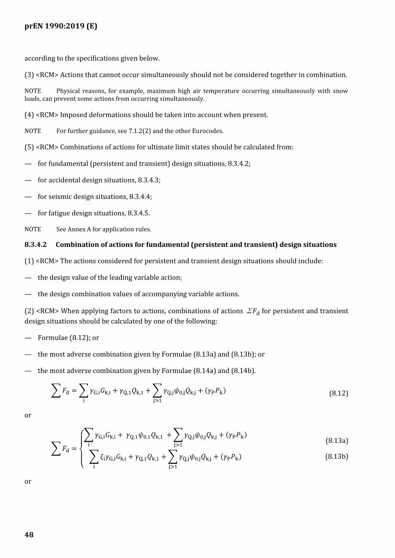
prEN 1990:2019 (E)
48
according to the specifications given below.
(3) <RCM> Actions that cannot occur simultaneously should not be considered together in combination.
NOTE Physical reasons, for example, maximum high air temperature occurring simultaneously with snow loads, can prevent some actions from occurring simultaneously.
(4) <RCM> Imposed deformations should be taken into account when present.
NOTE For further guidance, see 7.1.2(2) and the other Eurocodes.
(5) <RCM> Combinations of actions for ultimate limit states should be calculated from:
— for fundamental (persistent and transient) design situations, 8.3.4.2;
— for accidental design situations, 8.3.4.3;
— for seismic design situations, 8.3.4.4;
— for fatigue design situations, 8.3.4.5.
NOTE See Annex A for application rules.
8.3.4.2 Combination of actions for fundamental (persistent and transient) design situations
(1) <RCM> The actions considered for persistent and transient design situations should include:
— the design value of the leading variable action;
— the design combination values of accompanying variable actions.
(2) <RCM> When applying factors to actions, combinations of actions ΣFd for persistent and transient
design situations should be calculated by one of the following:
— Formulae (8.12); or
— the most adverse combination given by Formulae (8.13a) and (8.13b); or
— the most adverse combination given by Formulae (8.14a) and (8.14b).
∑𝐹d =∑𝛾G,i𝐺k,ii
+ 𝛾Q,1𝑄k,1 +∑𝛾Q,j𝜓0,j𝑄k,jj>1
+ (𝛾P𝑃k) (8.12)
or
∑𝐹d =
{
∑𝛾G,i𝐺k,i
i
+ 𝛾Q,1𝜓0,1𝑄k,1 +∑𝛾Q,j𝜓0,j𝑄k,jj>1
+ (𝛾P𝑃k)
∑𝜉i𝛾G,i𝐺k,ii
+ 𝛾Q,1𝑄k,1 +∑𝛾Q,j𝜓0,j𝑄k,jj>1
+ (𝛾P𝑃k)
(8.13a)
(8.13b)
or
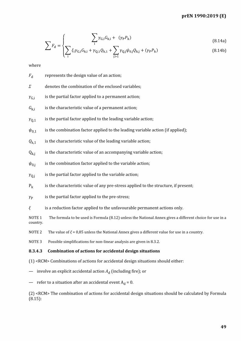
prEN 1990:2019 (E)
49
∑𝐹d =
{
∑𝛾G,i𝐺k,i
i
+ (𝛾P𝑃k)
∑𝜉i𝛾G,i𝐺k,ii
+ 𝛾Q,1𝑄k,1 +∑𝛾Q,j𝜓0,j𝑄k,jj>1
+ (𝛾P𝑃k)
(8.14a)
(8.14b)
where
Fd represents the design value of an action;
Σ denotes the combination of the enclosed variables;
γG,i is the partial factor applied to a permanent action;
Gk,i is the characteristic value of a permanent action;
γQ,1 is the partial factor applied to the leading variable action;
ψ0,1 is the combination factor applied to the leading variable action (if applied);
Qk,1 is the characteristic value of the leading variable action;
Qk,j is the characteristic value of an accompanying variable action;
ψ0,j is the combination factor applied to the variable action;
γQ,j is the partial factor applied to the variable action;
Pk is the characteristic value of any pre-stress applied to the structure, if present;
γP is the partial factor applied to the pre-stress;
ξ is a reduction factor applied to the unfavourable permanent actions only.
NOTE 1 The formula to be used is Formula (8.12) unless the National Annex gives a different choice for use in a country.
NOTE 2 The value of ξ = 0,85 unless the National Annex gives a different value for use in a country.
NOTE 3 Possible simplifications for non-linear analysis are given in 8.3.2.
8.3.4.3 Combination of actions for accidental design situations
(1) <RCM> Combinations of actions for accidental design situations should either:
— involve an explicit accidental action Ad (including fire); or
— refer to a situation after an accidental event Ad = 0.
(2) <RCM> The combination of actions for accidental design situations should be calculated by Formula (8.15):
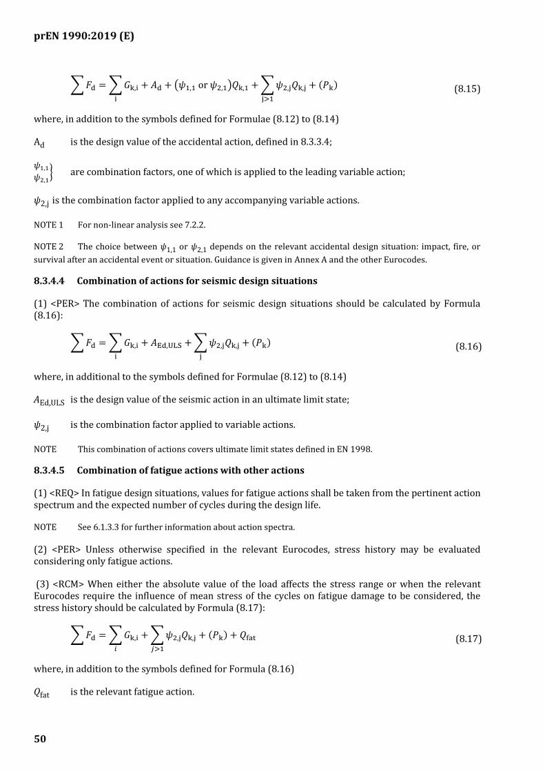
prEN 1990:2019 (E)
50
∑𝐹d =∑𝐺k,ii
+ 𝐴d + (𝜓1,1 or 𝜓2,1)𝑄k,1 +∑𝜓2,j𝑄k,jj>1
+ (𝑃k) (8.15)
where, in addition to the symbols defined for Formulae (8.12) to (8.14)
Ad is the design value of the accidental action, defined in 8.3.3.4;
𝜓1,1𝜓2,1
} are combination factors, one of which is applied to the leading variable action;
ψ2,j is the combination factor applied to any accompanying variable actions.
NOTE 1 For non-linear analysis see 7.2.2.
NOTE 2 The choice between ψ1,1 or ψ2,1 depends on the relevant accidental design situation: impact, fire, or
survival after an accidental event or situation. Guidance is given in Annex A and the other Eurocodes.
8.3.4.4 Combination of actions for seismic design situations
(1) <PER> The combination of actions for seismic design situations should be calculated by Formula (8.16):
∑𝐹d =∑𝐺k,ii
+ 𝐴Ed,ULS +∑𝜓2,j𝑄k,jj
+ (𝑃k) (8.16)
where, in additional to the symbols defined for Formulae (8.12) to (8.14)
AEd,ULS is the design value of the seismic action in an ultimate limit state;
ψ2,j is the combination factor applied to variable actions.
NOTE This combination of actions covers ultimate limit states defined in EN 1998.
8.3.4.5 Combination of fatigue actions with other actions
(1) <REQ> In fatigue design situations, values for fatigue actions shall be taken from the pertinent action spectrum and the expected number of cycles during the design life.
NOTE See 6.1.3.3 for further information about action spectra.
(2) <PER> Unless otherwise specified in the relevant Eurocodes, stress history may be evaluated considering only fatigue actions.
(3) <RCM> When either the absolute value of the load affects the stress range or when the relevant Eurocodes require the influence of mean stress of the cycles on fatigue damage to be considered, the stress history should be calculated by Formula (8.17):
∑𝐹d =∑𝐺k,i𝑖
+∑𝜓2,j𝑄k,j𝑗>1
+ (𝑃k) + 𝑄fat (8.17)
where, in addition to the symbols defined for Formula (8.16)
Qfat is the relevant fatigue action.
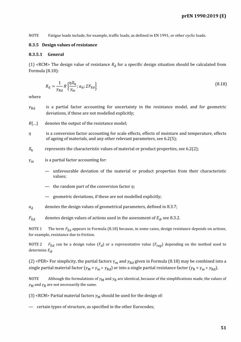
prEN 1990:2019 (E)
51
NOTE Fatigue loads include, for example, traffic loads, as defined in EN 1991, or other cyclic loads.
8.3.5 Design values of resistance
8.3.5.1 General
(1) <RCM> The design value of resistance Rd for a specific design situation should be calculated from
Formula (8.18):
𝑅d =1
𝛾Rd𝑅 {𝜂𝑋k𝛾m
; 𝑎d; 𝛴𝐹Ed} (8.18)
where
γRd is a partial factor accounting for uncertainty in the resistance model, and for geometric
deviations, if these are not modelled explicitly;
R{…} denotes the output of the resistance model;
η is a conversion factor accounting for scale effects, effects of moisture and temperature, effects of ageing of materials, and any other relevant parameters, see 6.2(5);
Xk represents the characteristic values of material or product properties, see 6.2(2);
γm is a partial factor accounting for:
— unfavourable deviation of the material or product properties from their characteristic values;
— the random part of the conversion factor η;
— geometric deviations, if these are not modelled explicitly;
ad denotes the design values of geometrical parameters, defined in 8.3.7;
FEd denotes design values of actions used in the assessment of Ed, see 8.3.2.
NOTE 1 The term FEd appears in Formula (8.18) because, in some cases, design resistance depends on actions,
for example, resistance due to friction.
NOTE 2 FEd can be a design value (Fd) or a representative value (Frep) depending on the method used to
determine Ed.
(2) <PER> For simplicity, the partial factors γm and γRd given in Formula (8.18) may be combined into a
single partial material factor (γM = γm γRd) or into a single partial resistance factor (γR = γm γRd).
NOTE Although the formulations of γM and γR are identical, because of the simplifications made, the values of
γM and γR are not necessarily the same.
(3) <RCM> Partial material factors γM should be used for the design of:
— certain types of structure, as specified in the other Eurocodes;
prEN 1990:2019 (E)
52
— certain types of geotechnical structure, as specified in EN 1997.
NOTE A simplified version of Formula (8.18) with factors applied to material properties is given in 8.3.5.2.
(4) <RCM> Partial resistance factors γR should be used for the design of:
— certain types of structure, as specified in the other Eurocodes;
— certain types of geotechnical structure, as specified in EN 1997.
NOTE A simplified version of Formula (8.18) with factors applied to resistance is given in 8.3.5.3.
8.3.5.2 Factors on material properties (the “material factor approach”, MFA)
(1) <RCM> When applying factors to material properties, the design value of resistance Rd should be
calculated from Formula (8.19):
𝑅d = 𝑅{𝑋d; 𝑎d; Σ𝐹Ed} = 𝑅 {𝜂𝑋k𝛾M
; 𝑎d; Σ𝐹Ed} (8.19)
where, further to symbols already defined for Formula (8.18)
Xd denotes the design values of material properties, defined in 8.3.6;
γM is defined in 8.3.5.1(3).
(2) <RCM> The values of the partial factors on material properties γM that are used in the verification of
ultimate limit states should be taken from the other Eurocodes.
8.3.5.3 Resistance factor approach (the "resistance factor approach", RFA)
(1) <RCM> When applying partial factors to resistance, its design value Rd should be calculated from
Formula (8.20):
𝑅d =𝑅{𝑋rep; 𝑎d; Σ𝐹Ed}
𝛾R=𝑅{𝜂𝑋k; 𝑎d; Σ𝐹Ed}
𝛾R (8.20)
where, further to symbols already defined for Formula (8.18)
Xrep denotes the representative values of material properties, defined as Xk;
γR is defined in 8.3.5.1(4).
(2) <PER> For structures or structural members that are analysed by non-linear methods and comprise more than one material, the design resistance Rd may be calculated from Formula (8.21):
𝑅d =1
𝛾R,1𝑅 {𝜂1𝑋k,1;
𝜂i𝑋k,i𝛾m,i 𝛾m,1⁄
; 𝑎d; 𝐹Ed} (8.21)
where, further to symbols already defined for Formula (8.18)
prEN 1990:2019 (E)
53
1 denotes factors applied to material 1;
i denotes factors applied to material i.
NOTE In some cases, the design resistance can be expressed by applying partial factors directly to individual resistances. See the other Eurocodes for further guidance.
(3) <RCM> The values of the partial factors on resistance γR that are used in the verification of ultimate
limit states should be taken from the other Eurocodes.
(4) <POS> Alternatively, in geotechnical design, the design value of resistance may be determined using prescriptive measures, as specified in EN 1997.
8.3.5.4 Fatigue
(1) <RCM> Using S-N curves given in the relevant Eurocodes, the design value of fatigue resistant stress range ΔσC,d should be calculated from Formula (8.22):
Δ𝜎C,d =Δ𝜎C𝛾Mf
(8.22)
where
ΔσC is the fatigue resistance corresponding to NC cycles to failure;
γMf is the partial factor for fatigue resistance.
NOTE 1 Values for γMf are given in the relevant Eurocodes.
NOTE 2 The partial factor for fatigue resistance accounts for the consequence of fatigue failure and the ease of inspection and repair of fatigue-sensitive members.
(2) <RCM> The relevant parties should be informed that structural members that are designed for a reduced fatigue life should be reassessed, repaired or replaced at the end of that fatigue life.
8.3.6 Design values of material properties
(1) <RCM> The design value of a material property Xd should be calculated from Formula (8.23):
𝑋d =𝑋rep
𝛾M=𝜂𝑋k𝛾M
(8.23)
where, in addition to the symbols defined for Formulae (8.19) and (8.20)
Xrep is the representative value of material or product property.
NOTE Values for η and γM are given in the other Eurocodes.
(2) <PER> Provided that the level of reliability is no less than that implied by the use of Formula (8.23), the design value of a material property may be determined directly from:
— empirical or theoretical relations with measured physical properties;

prEN 1990:2019 (E)
54
— physical and chemical composition;
— from previous experience;
— in geotechnical design, prescriptive measures;
— in geotechnical design, the most unfavourable value that the parameter could practically adopt;
— values given in European Standards or other documents that are specified in the other Eurocodes;
— reliability analysis, see Annex C; or
— results of tests, see Annex D.
NOTE Guidance on the assessment of design values of ground properties is given in EN 1997. Permission to use specific prescriptive measures is given in EN 1997.
(3) <RCM> When material or product properties are established directly, the more adverse of the upper and lower design values should be used in the verification of the limit state.
8.3.7 Design values of geometrical data
(1) <RCM> When the design of the structure is sensitive to deviations in a geometrical parameter, the design value of that parameter ad should be calculated from Formula (8.24):
𝑎d = 𝑎nom ±Δ𝑎 (8.24)
where
anom is the nominal value of the geometrical parameter;
Δa is a deviation that takes account of:
— unfavourable deviations from the nominal value;
— the cumulative effect of a simultaneous occurrence of several geometrical deviations.
NOTE 1 Examples of deviations in geometrical parameters include inaccuracy in the positioning of loads, location of supports, and dimensions of structural members.
NOTE 2 Effects of deviations in geometrical parameters can be important when second order effects are significant.
NOTE 3 The deviation of a geometrical parameter that is within tolerance is assumed to be catered for by the
partial factors γF, γM, γE, and γR.
NOTE 4 Tolerances are defined in the other Eurocodes or in the execution standards they refer to.
(2) <PER> When the design of the structure is not significantly sensitive to deviations in a geometrical parameter, the design value of parameter ad may be calculated from Formula (8.25):
𝑎𝑑 = 𝑎𝑛𝑜𝑚 (8.25)
prEN 1990:2019 (E)
55
(3) <PER> The design value of a geometrical imperfection id may be calculated from Formula (8.26):
𝑖𝑑 =Δ𝑎 (8.26)
NOTE The value of Δa can be given in the other Eurocodes.
8.4 Verification of serviceability limit states (SLS)
8.4.1 General
(1) <REQ> When checking serviceability limit states, the inequality given by Formula (8.27) shall be verified:
𝐸d ≤ 𝐶d,SLS (8.27)
where
Ed is the design value of the effects of actions specified in the serviceability criterion, determined
on the basis of the relevant combination;
Cd,SLS is the limiting design value of the relevant serviceability criterion.
8.4.2 Design values of the effects of actions
(1) <RCM> The design value of the effects of actions Ed for a specific combination of actions should be
calculated by Formula (8.28):
𝐸d = 𝐸{𝐹d; 𝑎d; 𝑋d} (8.28)
where
E{…} denotes the combined effect of the enclosed variables;
Fd represents the design values of actions, see 8.3.2.1, where, the value of γF = 1,0;
ad represents the design values of geometrical parameters, see 8.3.7;
Xd represents the design values of material properties, see 8.3.6.
NOTE 1 The term Xd appears in Formula (8.28) because, in general, effects of actions depend on material
properties, e.g. stiffness.
NOTE 2 The term ad appears in Formula (8.28) because effects of actions typically depend on the dimensions of
the structure.
8.4.3 Combinations of actions
8.4.3.1 General
(1) <RCM> The combinations of actions to be taken into account in the relevant design situations should be appropriate for the serviceability requirements and performance criteria being verified.
prEN 1990:2019 (E)
56
(2) <REQ> For each critical load case, the design values of the effects of actions Ed shall be determined by
combining the values of actions that are considered to occur simultaneously.
(3) <RCM> Combinations of actions ΣFd for serviceability limit states should be calculated from:
— for the characteristic combinations, 8.4.3.2;
— for the frequent combinations, 8.4.3.3;
— for quasi-permanent combinations, 8.4.3.4.
NOTE See Annex A for application rules.
(4) <RCM> Each combination of actions should include a leading variable action and any accompanying variable actions.
(5) <RCM> Imposed deformations should be taken into account where relevant.
NOTE For further guidance, see 7.1.2(3) and the other Eurocodes.
8.4.3.2 Characteristic combination of actions
(1) <RCM> For the characteristic combination, Formula (8.29) should be used:
∑𝐹d =∑𝐺k,ii
+ 𝑄k,1 +∑𝜓0,j𝑄k,jj>1
+ (𝑃k) (8.29)
where the symbols are as defined for Formulae (8.12) to (8.14).
NOTE Irreversible serviceability limit states are generally assessed using this combination of actions.
8.4.3.3 Frequent combination of actions
(1) <RCM> For the frequent combination, Formula (8.30) should be used:
∑𝐹d =∑𝐺k,ii
+ 𝜓1,1𝑄k,1 +∑𝜓2,j𝑄k,jj>1
+ (𝑃k) (8.30)
where, in addition to the symbols defined for Formula (8.29)
ψ1,j is the combination factor applied to the leading variable action;
ψ2,j is the combination factor applied to the accompanying variable actions.
NOTE 1 Reversible serviceability limit states are generally assessed using this combination of actions.
NOTE 2 The other Eurocodes can specify when this combination of actions is to be used.
prEN 1990:2019 (E)
57
8.4.3.4 Quasi-permanent combination of actions
(1) <RCM> For the quasi-permanent combination, Formula (8.31) should be used:
∑𝐹d =∑𝐺k,ii
+∑𝜓2,j𝑄k,jj
+ (𝑃k) (8.31)
where symbols are as defined for Formula (8.30).
NOTE 1 Long-term effects and the appearance of the structure are generally assessed using this combination of actions.
NOTE 2 The other Eurocodes can specify when this combination of actions is to be used.
8.4.3.5 Combination of actions in seismic design situations
(1) <RCM> For seismic design situations, Formula (8.32) should be used:
∑𝐹d =∑𝐺k,ii
+ 𝐴Ed,SLS +∑𝜓2,j𝑄k,jj
+ (𝑃k) (8.32)
where, in addition to the symbols defined for Formula (8.29)
AEd,SLS is the design value of the seismic action in a serviceability limit state, defined in EN 1998.
NOTE Depending on the magnitude of AEd,SLS, this combination of actions covers both the damage limitation
(DL) and fully operational (OP) serviceability limit states defined in EN 1998.
8.4.4 Design criteria
(1) <RCM> The deformations to be taken into account in relation to serviceability requirements should be either:
— as given in Annex A for different types of construction works; or
— as agreed with by the relevant authority or agreed for a specific project by the relevant parties.
NOTE 1 For other specific serviceability criteria such as crack width, stress or strain limitation, or slip resistance, see the other Eurocodes.
NOTE 2 Serviceability criteria for seismic design are given in EN 1998.
8.4.5 Design values of geometrical data
(1) <RCM> Design values of geometrical data for serviceability limit states should be chosen in accordance with 8.3.7, except as specified below.
(2) <PER> The deviation Δa may be taken as zero in the verification of serviceability limit states, unless the other Eurocodes specify differently.
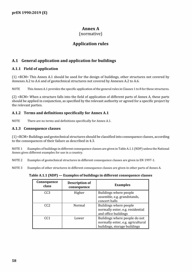
prEN 1990:2019 (E)
58
(normative)
Application rules
A.1 General application and application for buildings
A.1.1 Field of application
(1) <RCM> This Annex A.1 should be used for the design of buildings, other structures not covered by Annexes A.2 to A.6 and of geotechnical structures not covered by Annexes A.2 to A.6.
NOTE This Annex A.1 provides the specific application of the general rules in Clauses 1 to 8 for these structures.
(2) <RCM> When a structure falls into the field of application of different parts of Annex A, these parts should be applied in conjunction, as specified by the relevant authority or agreed for a specific project by the relevant parties.
A.1.2 Terms and definitions specifically for Annex A.1
NOTE There are no terms and definitions specifically for Annex A.1.
A.1.3 Consequence classes
(1) <RCM> Buildings and geotechnical structures should be classified into consequence classes, according to the consequences of their failure as described in 4.3.
NOTE 1 Examples of buildings in different consequence classes are given in Table A.1.1 (NDP) unless the National Annex gives different examples for use in a country.
NOTE 2 Examples of geotechnical structures in different consequence classes are given in EN 1997-1.
NOTE 3 Examples of other structures in different consequence classes are given in other parts of Annex A.
Table A.1.1 (NDP) — Examples of buildings in different consequence classes
Consequence class
Description of consequence
Examples
CC3 Higher Buildings where people assemble, e.g. grandstands, concert halls
CC2 Normal Buildings where people normally enter, e.g. residential and office buildings
CC1 Lower Buildings where people do not normally enter, e.g. agricultural buildings, storage buildings
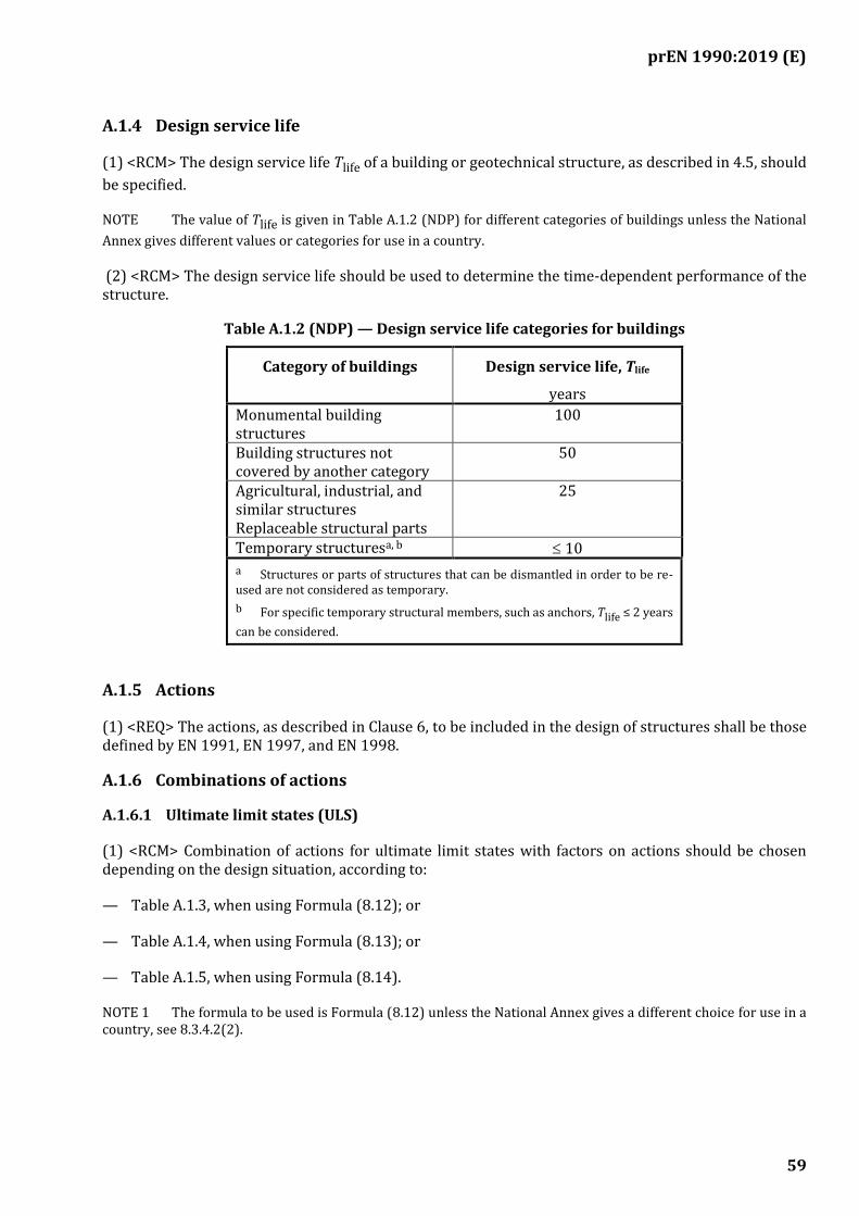
prEN 1990:2019 (E)
59
A.1.4 Design service life
(1) <RCM> The design service life Tlife of a building or geotechnical structure, as described in 4.5, should
be specified.
NOTE The value of Tlife is given in Table A.1.2 (NDP) for different categories of buildings unless the National
Annex gives different values or categories for use in a country.
(2) <RCM> The design service life should be used to determine the time-dependent performance of the structure.
Table A.1.2 (NDP) — Design service life categories for buildings
Category of buildings Design service life, Tlife
years
Monumental building structures
100
Building structures not covered by another category
50
Agricultural, industrial, and similar structures Replaceable structural parts
25
Temporary structuresa, b 10
a Structures or parts of structures that can be dismantled in order to be re-used are not considered as temporary.
b For specific temporary structural members, such as anchors, Tlife ≤ 2 years
can be considered.
A.1.5 Actions
(1) <REQ> The actions, as described in Clause 6, to be included in the design of structures shall be those defined by EN 1991, EN 1997, and EN 1998.
A.1.6 Combinations of actions
A.1.6.1 Ultimate limit states (ULS)
(1) <RCM> Combination of actions for ultimate limit states with factors on actions should be chosen depending on the design situation, according to:
— Table A.1.3, when using Formula (8.12); or
— Table A.1.4, when using Formula (8.13); or
— Table A.1.5, when using Formula (8.14).
NOTE 1 The formula to be used is Formula (8.12) unless the National Annex gives a different choice for use in a country, see 8.3.4.2(2).
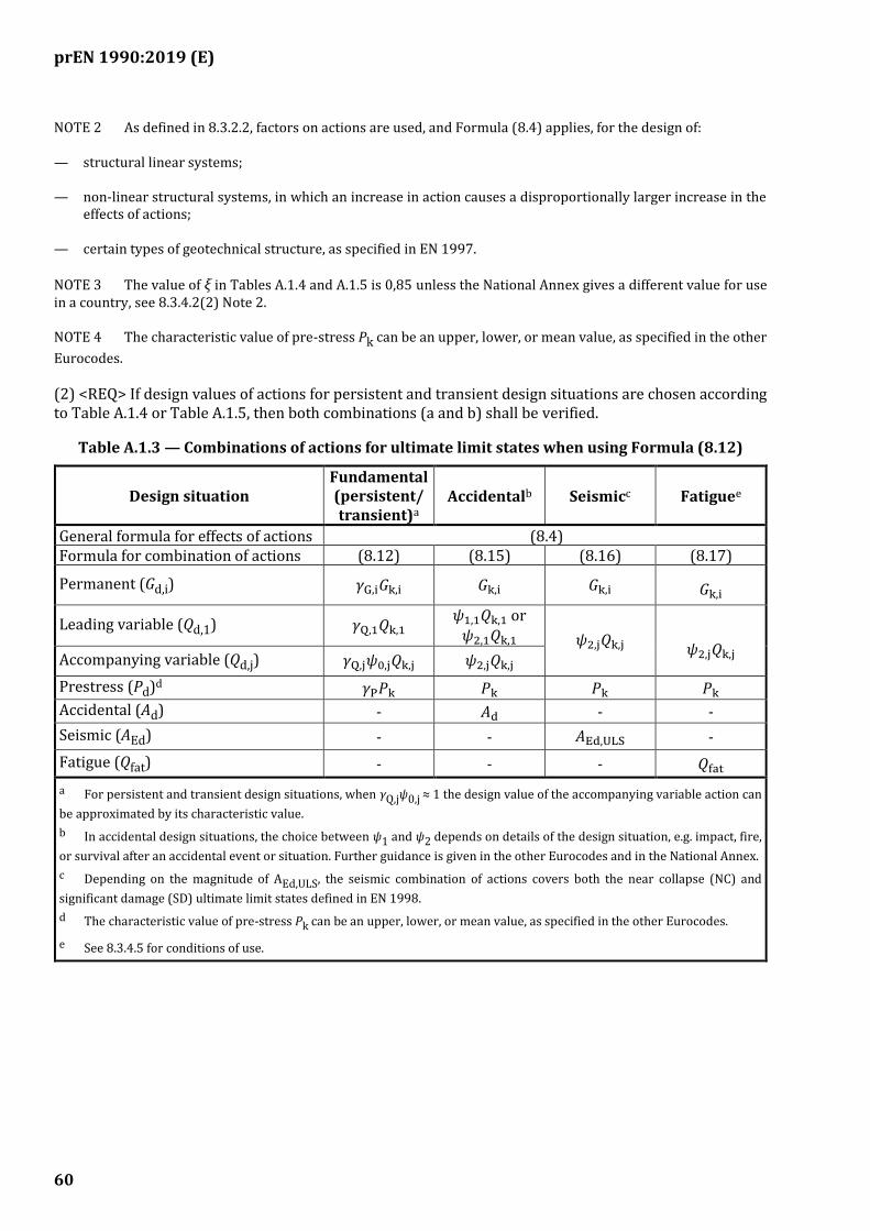
prEN 1990:2019 (E)
60
NOTE 2 As defined in 8.3.2.2, factors on actions are used, and Formula (8.4) applies, for the design of:
— structural linear systems;
— non-linear structural systems, in which an increase in action causes a disproportionally larger increase in the effects of actions;
— certain types of geotechnical structure, as specified in EN 1997.
NOTE 3 The value of ξ in Tables A.1.4 and A.1.5 is 0,85 unless the National Annex gives a different value for use in a country, see 8.3.4.2(2) Note 2.
NOTE 4 The characteristic value of pre-stress Pk can be an upper, lower, or mean value, as specified in the other
Eurocodes.
(2) <REQ> If design values of actions for persistent and transient design situations are chosen according to Table A.1.4 or Table A.1.5, then both combinations (a and b) shall be verified.
Table A.1.3 — Combinations of actions for ultimate limit states when using Formula (8.12)
Design situation Fundamental (persistent/ transient)a
Accidentalb Seismicc Fatiguee
General formula for effects of actions (8.4) Formula for combination of actions (8.12) (8.15) (8.16) (8.17)
Permanent (Gd,i) 𝛾G,i𝐺k,i 𝐺k,i 𝐺k,i 𝐺k,i
Leading variable (Qd,1) 𝛾Q,1𝑄k,1 𝜓1,1𝑄k,1 or 𝜓2,1𝑄k,1 𝜓2,j𝑄k,j
𝜓2,j𝑄k,j Accompanying variable (Qd,j) 𝛾Q,j𝜓0,j𝑄k,j 𝜓2,j𝑄k,j
Prestress (Pd)d 𝛾P𝑃k 𝑃k 𝑃k 𝑃k
Accidental (Ad) - 𝐴d - -
Seismic (AEd) - - 𝐴Ed,ULS -
Fatigue (Qfat) - - - 𝑄fat
a For persistent and transient design situations, when γQ,jψ0,j ≈ 1 the design value of the accompanying variable action can
be approximated by its characteristic value.
b In accidental design situations, the choice between ψ1 and ψ2 depends on details of the design situation, e.g. impact, fire,
or survival after an accidental event or situation. Further guidance is given in the other Eurocodes and in the National Annex.
c Depending on the magnitude of AEd,ULS, the seismic combination of actions covers both the near collapse (NC) and
significant damage (SD) ultimate limit states defined in EN 1998.
d The characteristic value of pre-stress Pk can be an upper, lower, or mean value, as specified in the other Eurocodes.
e See 8.3.4.5 for conditions of use.
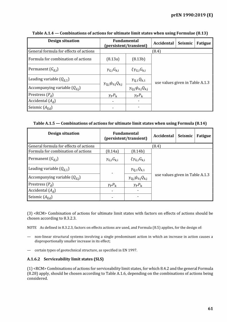
prEN 1990:2019 (E)
61
Table A.1.4 — Combinations of actions for ultimate limit states when using Formulae (8.13)
Table A.1.5 — Combinations of actions for ultimate limit states when using Formula (8.14)
Design situation Fundamental (persistent/transient)
Accidental Seismic Fatigue
General formula for effects of actions (8.4) Formula for combination of actions (8.14a) (8.14b)
use values given in Table A.1.3
Permanent (Gd,i) 𝛾G,i𝐺k,i 𝜉𝛾G,i𝐺k,i
Leading variable (Qd,1) -
𝛾Q,1𝑄k,1
Accompanying variable (Qd,j) 𝛾Q,j𝜓0,j𝑄k,j
Prestress (Pd) 𝛾P𝑃k 𝛾P𝑃k
Accidental (Ad) - -
Seismic (AEd) - -
(3) <RCM> Combination of actions for ultimate limit states with factors on effects of actions should be chosen according to 8.3.2.3.
NOTE As defined in 8.3.2.3, factors on effects actions are used, and Formula (8.5) applies, for the design of:
— non-linear structural systems involving a single predominant action in which an increase in action causes a disproportionally smaller increase in its effect;
— certain types of geotechnical structure, as specified in EN 1997.
A.1.6.2 Serviceability limit states (SLS)
(1) <RCM> Combinations of actions for serviceability limit states, for which 8.4.2 and the general Formula (8.28) apply, should be chosen according to Table A.1.6, depending on the combinations of actions being considered.
Design situation Fundamental (persistent/transient)
Accidental Seismic Fatigue
General formula for effects of actions (8.4)
Formula for combination of actions (8.13a) (8.13b)
use values given in Table A.1.3
Permanent (Gd,i) 𝛾G,i𝐺k,i 𝜉𝛾G,i𝐺k,i
Leading variable (Qd,1) 𝛾Q,j𝜓0,j𝑄k,j
𝛾Q,1𝑄k,1
Accompanying variable (Qd,j) 𝛾Q,j𝜓0,j𝑄k,j
Prestress (Pd) 𝛾P𝑃k 𝛾P𝑃k
Accidental (Ad) - -
Seismic (AEd) - -
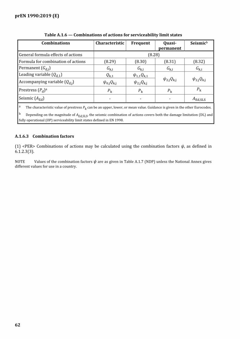
prEN 1990:2019 (E)
62
Table A.1.6 — Combinations of actions for serviceability limit states
Combinations Characteristic Frequent Quasi-permanent
Seismicb
General formula effects of actions (8.28)
Formula for combination of actions (8.29) (8.30) (8.31) (8.32)
Permanent (Gd,i) 𝐺k,i 𝐺k,i 𝐺k,i 𝐺k,i
Leading variable (Qd,1) 𝑄k,1 𝜓1,1𝑄k,1 𝜓2,j𝑄k,j 𝜓2,j𝑄k,j Accompanying variable (Qd,j) 𝜓0,j𝑄k,j 𝜓2,j𝑄k,j
Prestress (Pd)a 𝑃k 𝑃k 𝑃k 𝑃k
Seismic (AEd) - - - 𝐴Ed,SLS
a The characteristic value of prestress Pk can be an upper, lower, or mean value. Guidance is given in the other Eurocodes.
b Depending on the magnitude of AEd,SLS, the seismic combination of actions covers both the damage limitation (DL) and
fully operational (OP) serviceability limit states defined in EN 1998.
A.1.6.3 Combination factors
(1) <PER> Combinations of actions may be calculated using the combination factors ψ, as defined in 6.1.2.3(3).
NOTE Values of the combination factors ψ are as given in Table A.1.7 (NDP) unless the National Annex gives different values for use in a country.
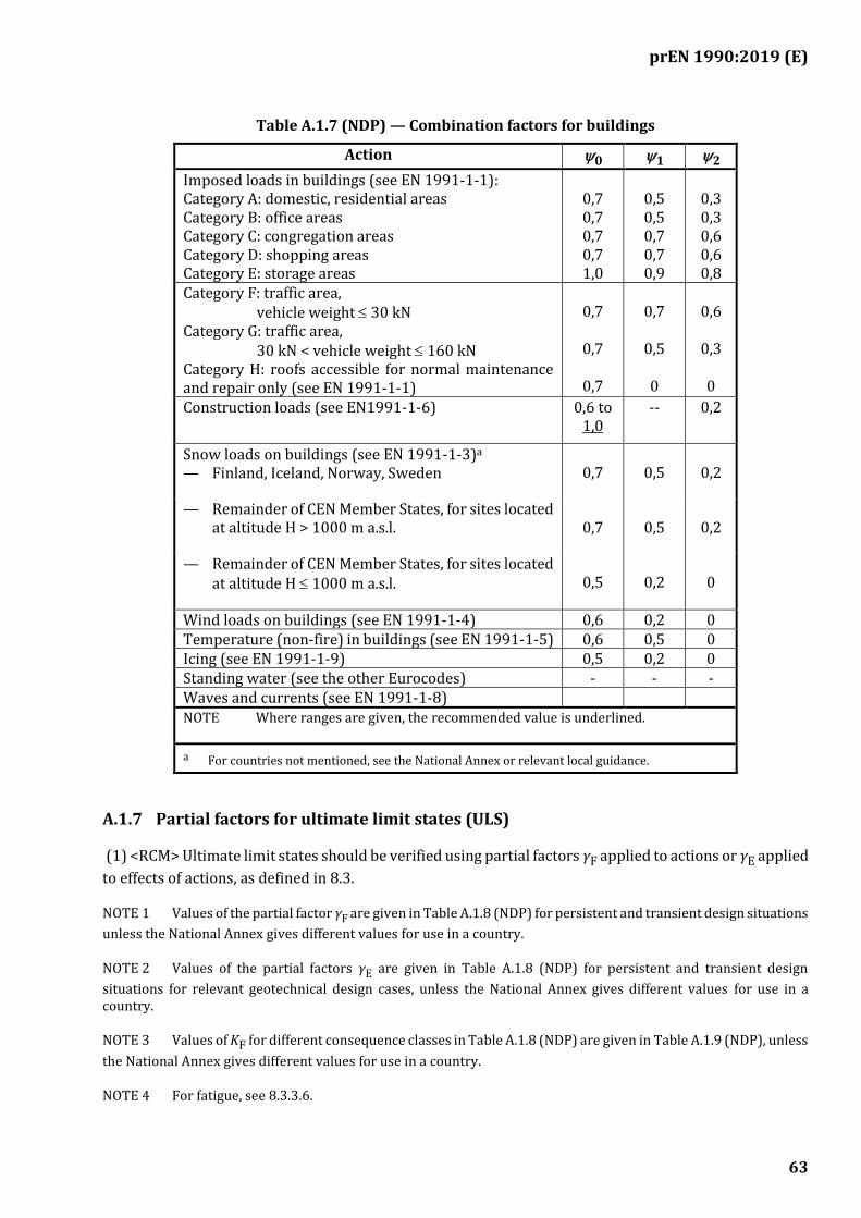
prEN 1990:2019 (E)
63
Table A.1.7 (NDP) — Combination factors for buildings
Action 0 1 2
Imposed loads in buildings (see EN 1991-1-1): Category A: domestic, residential areas Category B: office areas Category C: congregation areas Category D: shopping areas Category E: storage areas
0,7 0,7 0,7 0,7 1,0
0,5 0,5 0,7 0,7 0,9
0,3 0,3 0,6 0,6 0,8
Category F: traffic area, vehicle weight 30 kN Category G: traffic area, 30 kN < vehicle weight 160 kN Category H: roofs accessible for normal maintenance and repair only (see EN 1991-1-1)
0,7
0,7
0,7
0,7
0,5
0
0,6
0,3
0
Construction loads (see EN1991-1-6) 0,6 to 1,0
-- 0,2
Snow loads on buildings (see EN 1991-1-3)a — Finland, Iceland, Norway, Sweden
0,7
0,5
0,2
— Remainder of CEN Member States, for sites located at altitude H > 1000 m a.s.l.
0,7
0,5
0,2
— Remainder of CEN Member States, for sites located at altitude H 1000 m a.s.l.
0,5
0,2
0
Wind loads on buildings (see EN 1991-1-4) 0,6 0,2 0 Temperature (non-fire) in buildings (see EN 1991-1-5) 0,6 0,5 0 Icing (see EN 1991-1-9) 0,5 0,2 0 Standing water (see the other Eurocodes) - - - Waves and currents (see EN 1991-1-8) NOTE Where ranges are given, the recommended value is underlined.
a For countries not mentioned, see the National Annex or relevant local guidance.
A.1.7 Partial factors for ultimate limit states (ULS)
(1) <RCM> Ultimate limit states should be verified using partial factors γF applied to actions or γE applied
to effects of actions, as defined in 8.3.
NOTE 1 Values of the partial factor γF are given in Table A.1.8 (NDP) for persistent and transient design situations
unless the National Annex gives different values for use in a country.
NOTE 2 Values of the partial factors γE are given in Table A.1.8 (NDP) for persistent and transient design
situations for relevant geotechnical design cases, unless the National Annex gives different values for use in a country.
NOTE 3 Values of KF for different consequence classes in Table A.1.8 (NDP) are given in Table A.1.9 (NDP), unless
the National Annex gives different values for use in a country.
NOTE 4 For fatigue, see 8.3.3.6.

prEN 1990:2019 (E)
64
(2) <REQ> The value of the partial factors γF when applied to unfavourable actions or actions effects shall
not be less than 1,0.
(3) <REQ> When using Formulae (8.13b) and (8.14b), the value of ξγG shall not be less than 1,0.
(4) <RCM> Ultimate limit states that involve structural resistance should be verified using partial factors for Design Case 1.
(5) <RCM> When variations in the magnitude or spatial variation of permanent actions from the same source are significant, ultimate limit states that involve loss of static equilibrium should be verified using partial factors for Design Cases 2(a) and 2(b), using the whichever gives the less favourable design outcome.
(6) <PER> Verification of Design Case 2(b) may be omitted when it is obvious that verification using Design Case 2(a) governs the design outcome.
(7) <RCM> Ultimate limit states that involve failure of ground should be verified using partial factors for Design Cases 1, 2, 3 and 4, as specified in EN 1997.
NOTE EN 1997 gives guidance on which Design Cases to use for different geotechnical structures.
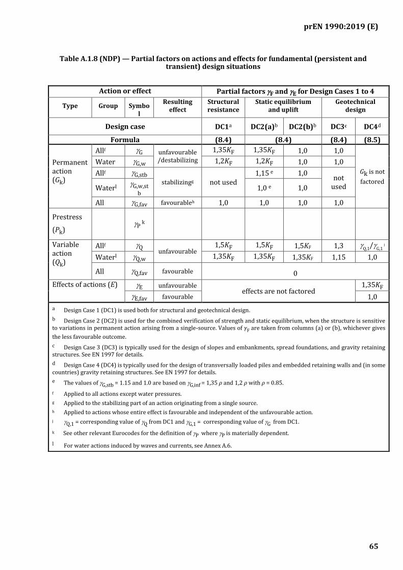
prEN 1990:2019 (E)
65
Table A.1.8 (NDP) — Partial factors on actions and effects for fundamental (persistent and transient) design situations
Action or effect Partial factors F and E for Design Cases 1 to 4
Type Group Symbol
Resulting effect
Structural resistance
Static equilibrium and uplift
Geotechnical design
Design case DC1a DC2(a)b DC2(b)b DC3c DC4d
Formula (8.4) (8.4) (8.4) (8.5)
Permanent action (Gk)
Allf G unfavourable /destabilizing
1,35KF 1,35KF 1,0 1,0
Gk is not
factored
Water G,w 1,2KF 1,2KF 1,0 1,0
Allf G,stb
stabilizingg not used 1,15
e 1,0 not
used Waterl G,w,st
b 1,0 e 1,0
All G,fav favourableh 1,0 1,0 1,0 1,0
Prestress
(Pk)
P k
Variable action (Qk)
Allf Q unfavourable
1,5KF 1,5KF 1,5KF 1,3 Q,1
/G,1 j
Waterl Q,w 1,35KF 1,35KF 1,35KF 1,15 1,0
All Q,fav favourable 0
Effects of actions (E) E unfavourable effects are not factored
1,35KF
E,fav favourable 1,0
a Design Case 1 (DC1) is used both for structural and geotechnical design.
b Design Case 2 (DC2) is used for the combined verification of strength and static equilibrium, when the structure is sensitive to variations in permanent action arising from a single-source. Values of γF are taken from columns (a) or (b), whichever gives
the less favourable outcome.
c Design Case 3 (DC3) is typically used for the design of slopes and embankments, spread foundations, and gravity retaining structures. See EN 1997 for details.
d Design Case 4 (DC4) is typically used for the design of transversally loaded piles and embedded retaining walls and (in some countries) gravity retaining structures. See EN 1997 for details.
e The values of G,stb = 1.15 and 1.0 are based on G,inf = 1,35 ρ and 1,2 ρ with ρ = 0.85.
f Applied to all actions except water pressures.
g Applied to the stabilizing part of an action originating from a single source.
h Applied to actions whose entire effect is favourable and independent of the unfavourable action.
j Q,1 = corresponding value of Q from DC1 and G,1 = corresponding value of G from DC1.
k See other relevant Eurocodes for the definition of P where P is materially dependent.
l For water actions induced by waves and currents, see Annex A.6.
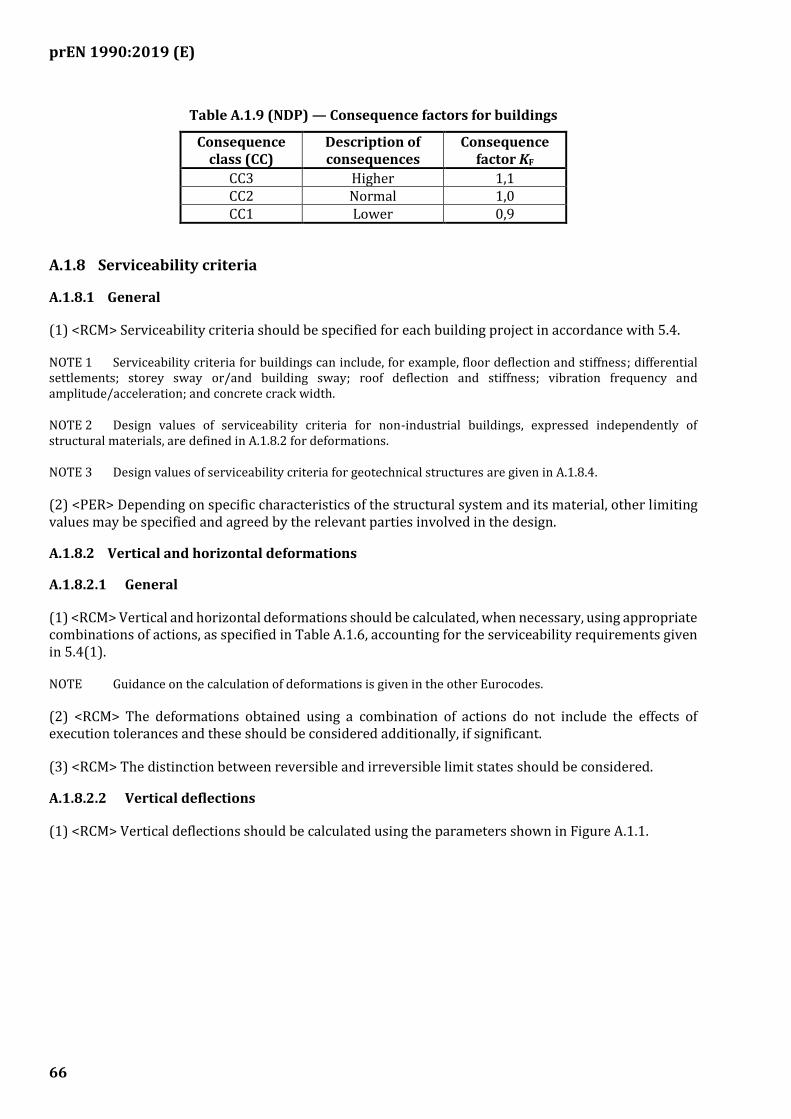
prEN 1990:2019 (E)
66
Table A.1.9 (NDP) — Consequence factors for buildings
Consequence class (CC)
Description of consequences
Consequence factor KF
CC3 Higher 1,1 CC2 Normal 1,0 CC1 Lower 0,9
A.1.8 Serviceability criteria
A.1.8.1 General
(1) <RCM> Serviceability criteria should be specified for each building project in accordance with 5.4.
NOTE 1 Serviceability criteria for buildings can include, for example, floor deflection and stiffness; differential settlements; storey sway or/and building sway; roof deflection and stiffness; vibration frequency and amplitude/acceleration; and concrete crack width.
NOTE 2 Design values of serviceability criteria for non-industrial buildings, expressed independently of structural materials, are defined in A.1.8.2 for deformations.
NOTE 3 Design values of serviceability criteria for geotechnical structures are given in A.1.8.4.
(2) <PER> Depending on specific characteristics of the structural system and its material, other limiting values may be specified and agreed by the relevant parties involved in the design.
A.1.8.2 Vertical and horizontal deformations
A.1.8.2.1 General
(1) <RCM> Vertical and horizontal deformations should be calculated, when necessary, using appropriate combinations of actions, as specified in Table A.1.6, accounting for the serviceability requirements given in 5.4(1).
NOTE Guidance on the calculation of deformations is given in the other Eurocodes.
(2) <RCM> The deformations obtained using a combination of actions do not include the effects of execution tolerances and these should be considered additionally, if significant.
(3) <RCM> The distinction between reversible and irreversible limit states should be considered.
A.1.8.2.2 Vertical deflections
(1) <RCM> Vertical deflections should be calculated using the parameters shown in Figure A.1.1.
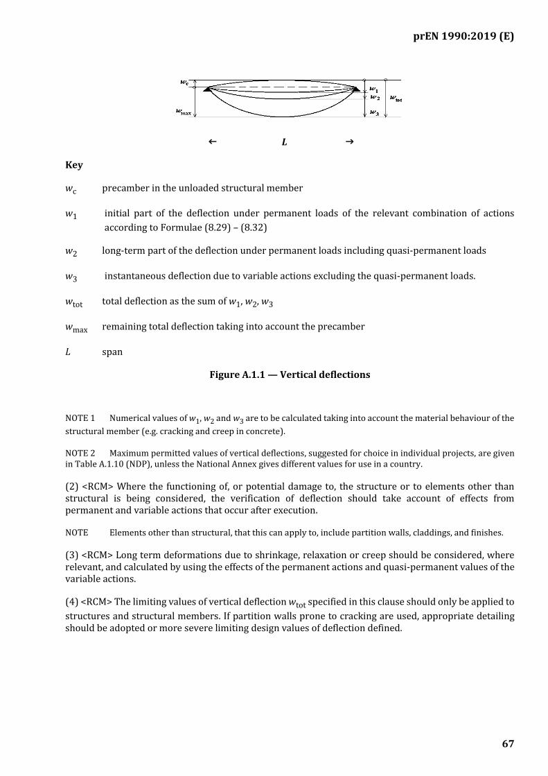
prEN 1990:2019 (E)
67
L
Key
wc precamber in the unloaded structural member
w1 initial part of the deflection under permanent loads of the relevant combination of actions
according to Formulae (8.29) – (8.32)
w2 long-term part of the deflection under permanent loads including quasi-permanent loads
w3 instantaneous deflection due to variable actions excluding the quasi-permanent loads.
wtot total deflection as the sum of w1, w2, w3
wmax remaining total deflection taking into account the precamber
L span
Figure A.1.1 — Vertical deflections
NOTE 1 Numerical values of w1, w2 and w3 are to be calculated taking into account the material behaviour of the
structural member (e.g. cracking and creep in concrete).
NOTE 2 Maximum permitted values of vertical deflections, suggested for choice in individual projects, are given in Table A.1.10 (NDP), unless the National Annex gives different values for use in a country.
(2) <RCM> Where the functioning of, or potential damage to, the structure or to elements other than structural is being considered, the verification of deflection should take account of effects from permanent and variable actions that occur after execution.
NOTE Elements other than structural, that this can apply to, include partition walls, claddings, and finishes.
(3) <RCM> Long term deformations due to shrinkage, relaxation or creep should be considered, where relevant, and calculated by using the effects of the permanent actions and quasi-permanent values of the variable actions.
(4) <RCM> The limiting values of vertical deflection wtot specified in this clause should only be applied to
structures and structural members. If partition walls prone to cracking are used, appropriate detailing should be adopted or more severe limiting design values of deflection defined.
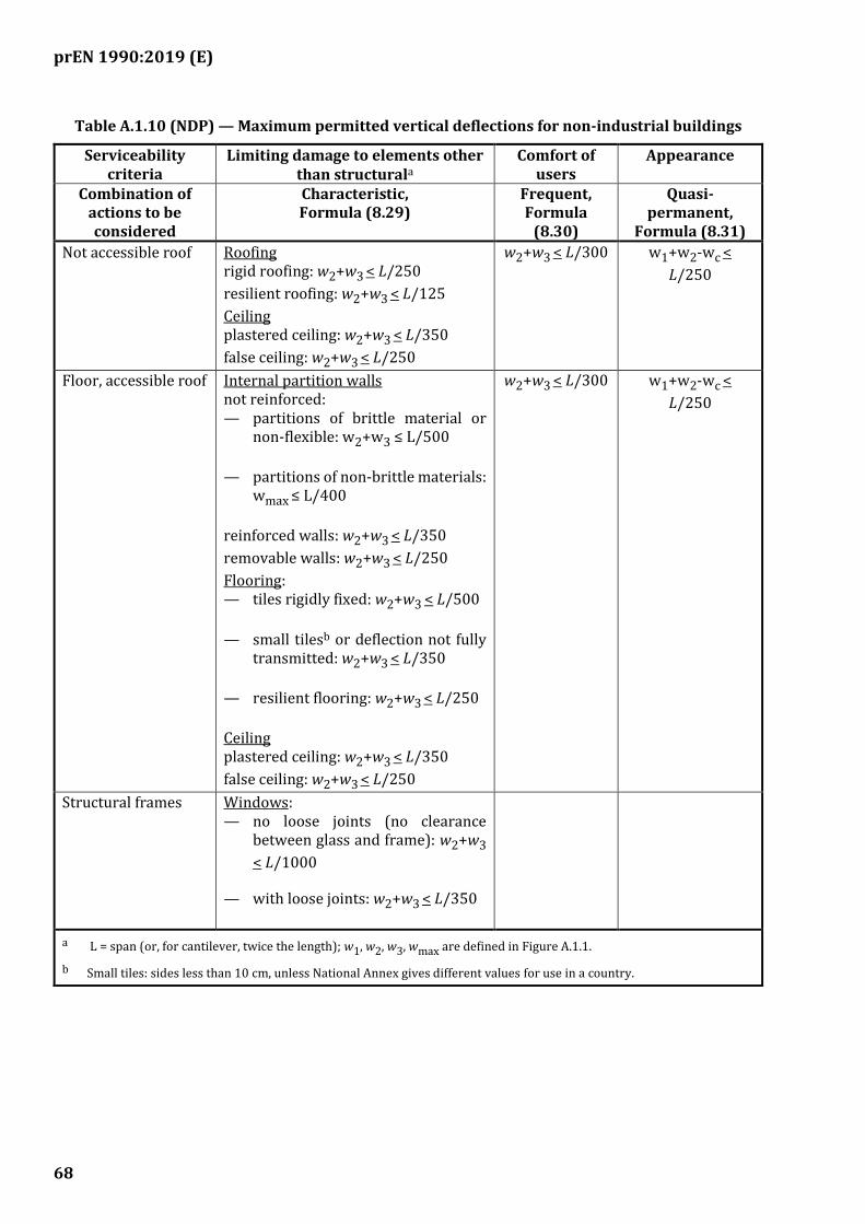
prEN 1990:2019 (E)
68
Table A.1.10 (NDP) — Maximum permitted vertical deflections for non-industrial buildings
Serviceability criteria
Limiting damage to elements other than structurala
Comfort of users
Appearance
Combination of actions to be considered
Characteristic, Formula (8.29)
Frequent, Formula
(8.30)
Quasi-permanent,
Formula (8.31)
Not accessible roof Roofing rigid roofing: w2+w3 < L/250
resilient roofing: w2+w3 < L/125
Ceiling plastered ceiling: w2+w3 < L/350
false ceiling: w2+w3 < L/250
w2+w3 < L/300 w1+w2-wc <
L/250
Floor, accessible roof Internal partition walls not reinforced: — partitions of brittle material or
non-flexible: w2+w3 ≤ L/500
— partitions of non-brittle materials: wmax ≤ L/400
reinforced walls: w2+w3 < L/350
removable walls: w2+w3 < L/250
Flooring: — tiles rigidly fixed: w2+w3 < L/500
— small tilesb or deflection not fully transmitted: w2+w3 < L/350
— resilient flooring: w2+w3 < L/250
Ceiling plastered ceiling: w2+w3 < L/350
false ceiling: w2+w3 < L/250
w2+w3 < L/300 w1+w2-wc <
L/250
Structural frames Windows: — no loose joints (no clearance
between glass and frame): w2+w3
< L/1000
— with loose joints: w2+w3 < L/350
a L = span (or, for cantilever, twice the length); w1, w2, w3, wmax are defined in Figure A.1.1.
b Small tiles: sides less than 10 cm, unless National Annex gives different values for use in a country.
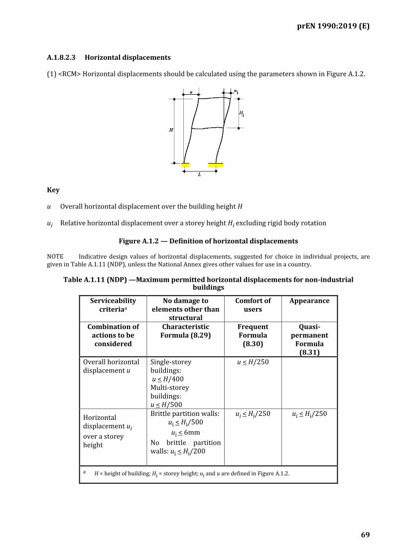
prEN 1990:2019 (E)
69
A.1.8.2.3 Horizontal displacements
(1) <RCM> Horizontal displacements should be calculated using the parameters shown in Figure A.1.2.
Key
u Overall horizontal displacement over the building height H
ui Relative horizontal displacement over a storey height Hi excluding rigid body rotation
Figure A.1.2 — Definition of horizontal displacements
NOTE Indicative design values of horizontal displacements, suggested for choice in individual projects, are given in Table A.1.11 (NDP), unless the National Annex gives other values for use in a country.
Table A.1.11 (NDP) —Maximum permitted horizontal displacements for non-industrial buildings
Serviceability criteriaa
No damage to elements other than
structural
Comfort of users
Appearance
Combination of actions to be considered
Characteristic Formula (8.29)
Frequent Formula
(8.30)
Quasi-permanent
Formula (8.31)
Overall horizontal displacement u
Single-storey buildings: u < H/400 Multi-storey buildings: u < H/500
u < H/250
Horizontal displacement ui
over a storey height
Brittle partition walls: ui < Hi/500
ui < 6mm
No brittle partition walls: ui < Hi/200
ui < Hi/250
ui < Hi/250
a H = height of building; Hi = storey height; ui and u are defined in Figure A.1.2.

prEN 1990:2019 (E)
70
A.1.8.3 Vibrations
(1) <RCM> To achieve satisfactory vibration behaviour of buildings and their structural members under serviceability conditions, the following aspects, amongst others, should be considered:
— the comfort of the user;
— the functioning of the structure or its structural members, e.g. resulting from cracks in partitions, damage to cladding, sensitivity of building contents to vibrations;
— other aspects agreed with the relevant authority or agreed for a specific project by the relevant parties.
(2) <RCM> For the serviceability limit states of a structure or a structural member not to be exceeded when subjected to vibrations, the natural frequency of vibrations of the structure or structural member should be kept above appropriate values (which depend upon the function of the building, the structural materials and the source of the vibration), as specified by the relevant authority or agreed for the project by the relevant parties.
NOTE 1 SLS due to vibrations are to be considered e.g. for hospitals, laboratories, gymnasia and sport halls, dance rooms, concert halls, and for floors, stircases and balconies in general.
NOTE 2 Further guidance is given in the other Eurocodes.
(3) <RCM> If a natural vibration frequency of the structure is lower than the appropriate value, a more refined analysis of the dynamic response of the structure, including the consideration of damping, should be performed.
NOTE For further guidance, see EN 1991-1-1, EN 1991-1-4, and ISO 10137.
(4) <RCM> The sources of vibration should be specified for each project and agreed with the relevant authority or parties.
NOTE Possible sources of vibration include walking, synchronised movements of people, machinery, ground borne vibrations from traffic, and wind actions.
A.1.8.4 Limiting foundation movements
(1) <REQ> The design value of the serviceability criteria Cd,SLS for foundation movement beneath a
building shall be selected during the design of the supported structure.
(2) <RCM> The sensitivity of a structure to foundation movement should be classified according to Table A.1.12, separately for different modes of foundation movement.
NOTE Examples of buildings in different structural sensitivity classes are given in Table A.1.16 (NDP) unless the National Annex gives different examples.
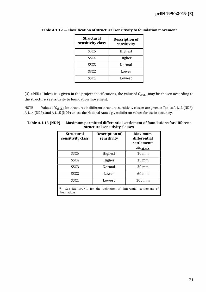
prEN 1990:2019 (E)
71
Table A.1.12 —Classification of structural sensitivity to foundation movement
Structural sensitivity class
Description of sensitivity
SSC5 Highest
SSC4 Higher
SSC3 Normal
SSC2 Lower
SSC1 Lowest
(3) <PER> Unless it is given in the project specifications, the value of Cd,SLS may be chosen according to
the structure’s sensitivity to foundation movement.
NOTE Values of Cd,SLS for structures in different structural sensitivity classes are given in Tables A.1.13 (NDP),
A.1.14 (NDP), and A.1.15 (NDP) unless the National Annex gives different values for use in a country.
Table A.1.13 (NDP) — Maximum permitted differential settlement of foundations for different structural sensitivity classes
Structural sensitivity class
Description of sensitivity
Maximum differential settlementa
sCd,SLS
SSC5 Highest 10 mm
SSC4 Higher 15 mm
SSC3 Normal 30 mm
SSC2 Lower 60 mm
SSC1 Lowest 100 mm
a See EN 1997-1 for the definition of differential settlement of foundations.
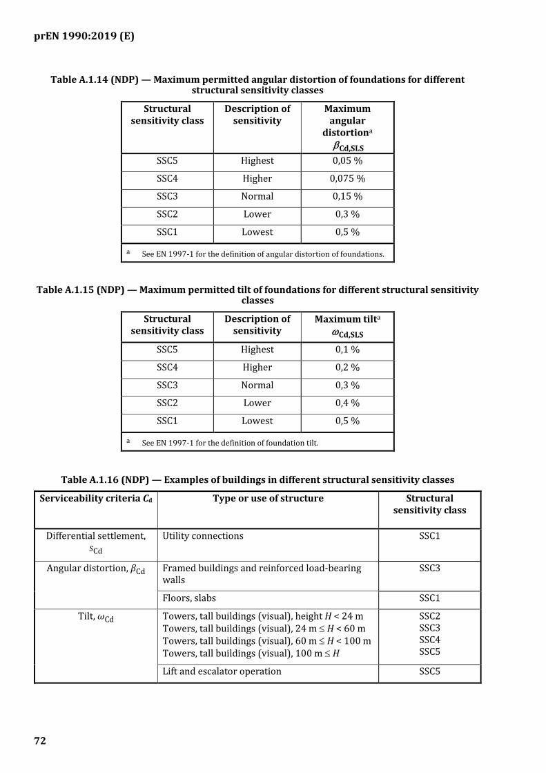
prEN 1990:2019 (E)
72
Table A.1.14 (NDP) — Maximum permitted angular distortion of foundations for different structural sensitivity classes
Structural sensitivity class
Description of sensitivity
Maximum angular
distortiona
Cd,SLS
SSC5 Highest 0,05 %
SSC4 Higher 0,075 %
SSC3 Normal 0,15 %
SSC2 Lower 0,3 %
SSC1 Lowest 0,5 %
a See EN 1997-1 for the definition of angular distortion of foundations.
Table A.1.15 (NDP) — Maximum permitted tilt of foundations for different structural sensitivity classes
Structural sensitivity class
Description of sensitivity
Maximum tilta Cd,SLS
SSC5 Highest 0,1 %
SSC4 Higher 0,2 %
SSC3 Normal 0,3 %
SSC2 Lower 0,4 %
SSC1 Lowest 0,5 %
a See EN 1997-1 for the definition of foundation tilt.
Table A.1.16 (NDP) — Examples of buildings in different structural sensitivity classes
Serviceability criteria Cd Type or use of structure Structural sensitivity class
Differential settlement, sCd
Utility connections SSC1
Angular distortion, βCd Framed buildings and reinforced load-bearing walls
SSC3
Floors, slabs SSC1
Tilt, ωCd Towers, tall buildings (visual), height H < 24 m Towers, tall buildings (visual), 24 m H < 60 m Towers, tall buildings (visual), 60 m H < 100 m Towers, tall buildings (visual), 100 m H
SSC2 SSC3 SSC4 SSC5
Lift and escalator operation SSC5
prEN 1990:2019 (E)
73
A.2 Application for bridges
[Drafting note: Annex A.2 will be included in a subsequent amendment]
A.2.1 Field of application
A.2.2 Terms and definitions specifically for Annex A.2
A.2.3 Design service life
A.2.4 Consequence classes
A.2.5 Actions
A.2.6 Combinations of actions (including psi values)
A.2.7 Partial factors
A.2.8 Serviceability criteria
A.2.9 Fatigue
A.3 Application for towers, masts and chimneys
[Drafting note: Annex A.3 will be included in a subsequent amendment]
A.3.1 Field of application
A.3.2 Terms and definitions specifically for Annex A.3
A.3.3 Consequence classes
A.3.4 Design service life
A.3.5 Actions
A.3.6 Combinations of actions (including values)
A.3.7 Partial factors
A.3.8 Serviceability criteria
A.3.9 Fatigue
prEN 1990:2019 (E)
74
A.4 Application for silos and tanks
[Drafting note: Annex A.4 will be included in a subsequent amendment]
A.4.1 Field of application
A.4.2 Terms and definitions specifically for Annex A.4
A.4.3 Consequence classes
A.4.4 Design service life
A.4.5 Actions
A.4.6 Combinations of actions
A.4.7 Partial factors
A.4.8 Serviceability criteria
A.4.9 Fatigue
A.5 Application for structures supporting cranes
[Drafting note: Annex A.5 will be included in a subsequent amendment]
A.5.1 Scope and field of application
A.5.2 Terms and definitions specifically for Annex A.5
A.5.3 Consequence classes
A.5.4 Design service life
A.5.5 Actions
A.5.6 Combinations of actions
A.5.7 Partial factors
A.5.8 Serviceability criteria
A.5.9 Fatigue
prEN 1990:2019 (E)
75
A.6 Application for marine coastal structures
[Drafting note: Annex A.6 will be included in a subsequent amendment]
A.6.1 Field of application
A.6.2 Terms and definitions specifically for Annex A.6
A.6.3 Design service life
A.6.4 Consequence Classes
A.6.5 Actions
A.6.6 Combinations of actions (including psi values)
A.6.7 Partial Factors
A.6.8 Serviceability criteria
A.6.9 Fatigue

prEN 1990:2019 (E)
76
(informative)
Technical management measures for design and execution
B.1 Use of this informative Annex
(1) This informative Annex provides supplementary guidance to that given in 4.8, for technical management measures covering design and execution to meet the assumptions given in 1.2.
NOTE 1 National choice on the application of this Informative Annex is given in the National Annex. If the National Annex contains no information on the application of this informative annex, it can be used.
NOTE 2 Special requirements regarding the roles and responsibilities, qualifications and experience of personnel involved in the construction process, can be specified in the National Annex for use in a country or for a specific project.
B.2 Scope and field of application
(1) This informative Annex covers technical management measures for:
— design quality;
— design checking;
— execution quality;
— inspection during execution;
in order for the intended level of structural reliability of a structure (or part of structure) designed and executed according to the Eurocodes to be achieved.
NOTE The implementation of this informative Annex depends on the legal system in force in each country. This Annex is provided as guidance to the writers of the National Annexes to enable a consistent approach across Europe.
B.3 Choice of technical management measures
(1) <RCM> The technical management measures should be chosen relevant to the selected consequence classes (see 4.3).
NOTE See B.8 for the selection of appropriate technical management measures.
B.4 Design quality
(1) The term 'quality', as used within the design and execution process of structures, deals with use of adequate technical knowledge and its correct application to achieve the required mechanical resistance, stability, serviceability, and durability of a structure.
(2) <RCM> The personnel responsible for the design of a structure should have appropriate qualification and experience, depending on the consequences of failure of the structure and the complexity of its design.

prEN 1990:2019 (E)
77
NOTE 1 Appropriate qualification and experience of personnel designing structures can be defined in the National Annex for use in a country and/or for a specific project or types of project.
NOTE 2 Requirements can be added related to the establishment of project specific and detailed routines, and clearly defined roles and responsibilities of personnel, where relevant. The requirements to be added can be specified in the National Annex for use in a country.
(3) <PER> Design qualification and experience levels (DQLs) may be used to determine the method of establishing that the personnel responsible for the design of a structure meet the corresponding assumptions given in 1.2.
NOTE The minimum qualification and experience of personnel for each DQL are given in Table B.1 (NDP) unless the National Annex gives different design qualification and experience levels for us in a country.
Table B.1 (NDP) — Design qualification and experience levels (DQL)
B.5 Design checking
(1) <REQ> The design shall be checked to reduce the risk of human errors that might have arisen during the design process.
(2) <PER> Design check levels (DCLs) may be used to determine the method of establishing that the design meets the corresponding assumptions given in 1.2.
NOTE 1 The level of design checking for each DCL is given in Table B.2 (NDP) unless the National Annex gives different design check levels for use in a country.
NOTE 2 The minimum design checking can be specified for a specific project or types of project.
Table B.2 (NDP) — Design check levels (DCL)
DCL Design checking Required level
DCL3 Independent extended checkinga Can be defined nationally
DCL2 Independent normal checkinga Can be defined nationally
DCL1 Self-checking Can be defined nationally
a The term can be defined nationally.
(3) <REQ> Self-checking shall be performed for all designs.
DQL Design qualification and experience of personnel Required level
DQL3 Have the required level of design qualification and experience to perform complex design works
Can be defined nationally
DQL2 Have the required level of design qualification and experience
to perform advanced design works
Can be defined
nationally
DQL1 Have the required level of design qualification and experience to perform simple design works
Can be defined nationally

prEN 1990:2019 (E)
78
(4) <RCM> Design checking should include:
— loads, models for calculation of loads and design situations;
— structural models, calculation of load effects and design verification;
— adequate knowledge of ground conditions and the design parameters;
— where appropriate, separate calculations as alternatives to reviewing the design calculations;
— consistency of calculations, drawings, detailing and the execution specification.
(5) <RCM> Measures for design checking should concentrate on those parts of a structure where failure would have larger consequences with respect to structural resistance, durability, and function.
B.6 Execution quality
(1) <REQ> Execution and execution quality assurance for structures and structural products shall be in accordance with the European standards on execution.
(2) <RCM> When no European standards on execution exist, the contractor should have a management system that provides appropriate levels of skill and experience and qualifications for the execution of the works.
NOTE 1 The assumptions given in 1.2(3), assume personnel to have the appropriate skill and experience to execute the works.
NOTE 2 The required level of skill and experience and the qualifications for the execution of the works can be defined nationally.
(3) <RCM> Where an Assessment of Verification of Consistency of Products (AVCP)-System is required in harmonised technical specifications (European Product Standard (EN) or European Assessment Document (EAD)) for products or materials used in the structure, the manufacturer should carry out, under a system of a Production Quality Management (PQM), a factory production control based on a quality assurance plan and following the AVCP-System.
(4) <RCM> For any material or product used in the structure for which the AVCP-System is unknown or not established, a comparable control procedure should be applied.
B.7 Inspection during execution
(1) <REQ> Inspection during execution shall be undertaken to check the compliance of the execution with the design and the execution specification and to reduce human errors during execution.
NOTE The term “execution specification” covers e.g. calculations, drawings, descriptions of the works, choice of the products, execution classes, tolerance classes, etc.
(2) <PER> Inspection levels (ILs) may be used to determine the method of establishing that the execution meets the corresponding assumptions given in 1.2.
NOTE 1 The level of inspection for each IL is given in Table B.3 (NDP) unless the National Annex gives different inspection levels for use in a country.
NOTE 2 The minimum inspection during execution can be specified for a specific project or types of project.

prEN 1990:2019 (E)
79
Table B.3 (NDP) — Inspection levels (IL)
IL Inspection Required level
IL3 Independent extended inspectiona Can be defined nationally
IL2 Independent normal inspectiona Can be defined nationally
IL1 Self inspection Can be defined nationally
a The term can be defined nationally.
(3) <REQ> Self-inspection shall be carried out for all execution.
(4) <RCM> Inspection should ensure that:
— the execution specifications are available during manufacturing and execution;
— the execution is performed according to the execution specification;
— the personnel have the skills and training required for the work;
— inspection is properly documented;
— materials and construction products used are as specified.
(5) <RCM> Measures for inspection should concentrate on those parts of a structure where failure would have larger consequences with respect to structural resistance, durability, and function.
B.8 Technical management measures
(1) <RCM> The DQL, DCL, and IL should be chosen according to the consequences of failure.
NOTE The minimum DQL, DCL, and IL are given in Table B.4 (NDP) unless the National Annex gives different minima for use in a country.
(2) <RCM> For geotechnical structures, the DQL, DCL, and IL should be chosen according to the consequences of failure and the complexity of the ground, as specified in EN 1997-1.
Table B.4 (NDP) — Minimum design quality level, design check level, execution class and inspection level for different consequence classes
Consequence class
Minimum design quality
level (DQL)
Minimum design check level (DCL)
Minimum execution
class (EXC)
Minimum inspection level (IL)
CC3 DQL3 DCL3 See relevant execution and
product standards
IL3
CC2 DQL2 DCL2 IL2
CC1 DQL1 DCL1 IL1
prEN 1990:2019 (E)
80
(informative)
Reliability analysis and code calibration
C.1 Use of this informative Annex
(1) This informative Annex provides guidance on reliability-based methods of analysis and on the calibration of partial factors.
NOTE National choice on the application of this Informative Annex is given in the National Annex. If the National Annex contains no information on the application of this informative annex, it can be used.
C.2 Scope and field of application
(1) Annex C.3 provides the basis for the reliability verification formats that can be used within the Eurocodes. Information and theoretical background and the reliability-based calibration of the partial factor method described in Clause 5 and Annex A are given. This Annex also provides the background to Annex D, and is relevant to the contents of Annex B.
(2) Annex C.3 also provides information on:
— structural reliability assessment;
— application of reliability-based methods to determine design values of partial factors in design formulae by calibration.
NOTE The majority of structures can be designed according to the Eurocodes without applying the methods presented in this Annex. These methods can, however, be useful for design situations that are not well covered and for possible extensions of the standard.
(3) Annex C.4 sets out principles for reliability-based code-calibration and corresponding guidance for possible extensions and developments of the partial factor design method.
NOTE Calibration and verification of partial factors is done by national competent authorities.
C.3 Basis for reliability analysis and partial factor design
C.3.1 Overview of reliability verification approaches
(1) <REQ> In order to verify whether a structure complies with reliability requirements for all design and assessment situations, one of the following approaches, with corresponding criteria, shall be chosen:
— Semi-probabilistic, in which the structure fulfils a set of inequalities using specified design values of the basic variables; or
— Reliability-based, in which the structure fulfils a set of reliability requirements; or
— Risk-informed, in which the sum of all costs (building, maintenance, etc.) and economic risks (with respect to failure or malfunctioning) is minimized while ensuring that aspects of human safety are consistent with the preferences of the society.

prEN 1990:2019 (E)
81
NOTE The choice between these approaches is made according to (3) – (6).
(2) <RCM> In order to assess structural performance, structural responses should be divided into two domains: desirable and undesirable states. The boundary between these domains is called the limit state. ‘Failure’ is defined as entering the undesirable state (see 5.2).
NOTE According to this definition, ‘failure’ can also refer to limit states, where structural capacity is not involved, e.g. a serviceability limit state.
(3) <RCM> Except where stated otherwise in the Eurocodes, the semi-probabilistic approach via a partial factor design format should be applied in all design situations.
(4) <PER> The reliability-based approach may be applied to design situations where uncertainties in the representation of loads, load effects, material resistances, and system-effects mean that the reliability-based approach gives a significantly better representation of reality than the partial factor design format.
NOTE 1 The relevant authority can authorize the use of the reliability-based approach and give specific conditions for its use.
NOTE 2 Design situations that are not covered by the partial factor design format can include:
— situations where relevant loads or hazard scenarios are not covered by EN 1991;
— the use of building materials or combination of different materials outside the usual application domain, e.g. new materials, behaviour at very high temperatures;
— ground conditions, such as rock, which are strongly affected by discontinuities and other geometrical phenomena.
(5) <RCM> The reliability based approach should also be used for the calibration of partial factors in the semi-probabilistic approach, see Annex C.4.
NOTE Calibration of partial factors is performed by National Standards Bodies, not designers.
(6) <PER> The use of the risk-informed approach may apply to design situations where both the uncertainties and the consequences are outside common ranges.
NOTE 1 Design situations where the uncertainties and the consequences are outside common ranges include, for example, those associated with accidents and those which clearly deviate from situations generally covered by the Eurocodes.
NOTE 2 No further guidance on the risk-informed approach is given in this Annex. Relevant guidance can be found in ISO 2394:2015.
NOTE 3 Figure C.3.1 presents a diagrammatic overview of the various methods for the verification of the adequate reliable performance of structures.
(7) <REQ> Risk-informed and reliability-based approaches shall only be employed if uncertainties are represented consistently based on unbiased assumptions.
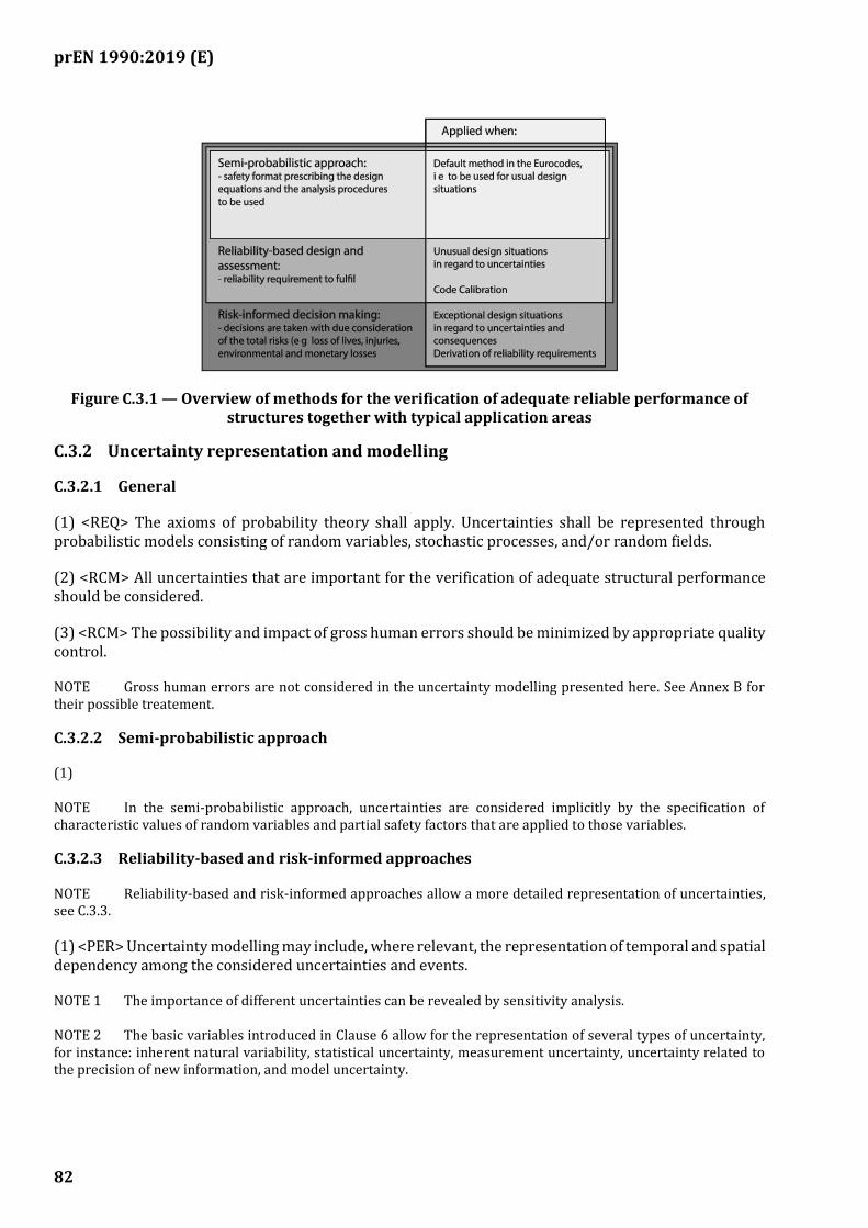
prEN 1990:2019 (E)
82
Figure C.3.1 — Overview of methods for the verification of adequate reliable performance of structures together with typical application areas
C.3.2 Uncertainty representation and modelling
C.3.2.1 General
(1) <REQ> The axioms of probability theory shall apply. Uncertainties shall be represented through probabilistic models consisting of random variables, stochastic processes, and/or random fields.
(2) <RCM> All uncertainties that are important for the verification of adequate structural performance should be considered.
(3) <RCM> The possibility and impact of gross human errors should be minimized by appropriate quality control.
NOTE Gross human errors are not considered in the uncertainty modelling presented here. See Annex B for their possible treatement.
C.3.2.2 Semi-probabilistic approach
(1)
NOTE In the semi-probabilistic approach, uncertainties are considered implicitly by the specification of characteristic values of random variables and partial safety factors that are applied to those variables.
C.3.2.3 Reliability-based and risk-informed approaches
NOTE Reliability-based and risk-informed approaches allow a more detailed representation of uncertainties, see C.3.3.
(1) <PER> Uncertainty modelling may include, where relevant, the representation of temporal and spatial dependency among the considered uncertainties and events.
NOTE 1 The importance of different uncertainties can be revealed by sensitivity analysis.
NOTE 2 The basic variables introduced in Clause 6 allow for the representation of several types of uncertainty, for instance: inherent natural variability, statistical uncertainty, measurement uncertainty, uncertainty related to the precision of new information, and model uncertainty.
prEN 1990:2019 (E)
83
(2) <RCM> The quantification of uncertainties and their probabilistic representation should incorporate both subjective information and available evidence. Bayesian probability theory, which provides a consistent framework for the treatment of different types of information, should be used.
(3) <RCM> The description of uncertain quantities by probabilistic models should correspond to well-defined sets of populations.
NOTE The results of the application of risk-informed or reliability-based approaches are only valid for the same sets.
C.3.3 Reliability-based design
C.3.3.1 General
(1) <REQ> Following the reliability-based approach, decisions with respect to the design of structures shall take basis in reliability assessments, which ensure that the structure meets defined reliability requirements.
NOTE Reliability assessment involves the estimation of the probability of adverse events. Adverse events are events that include consequences and are conventionally termed 'failure events'.
(2) <RCM> Failure events should be represented by limit states.
(3) <PER> Where analytical models for the representation of adverse events or failure events are available, the limit state function g() may be represented by Formula (C.3.1):
( ( )) 0g t =X (C.3.1)
The time-variant basic variables X(t) may be represented by Formula (C.3.2):
1 2( ) ( ), ( ),...t X t X t=X (C.3.2)
The domain of adverse (failure), events ( )( )t x is given by Formula (C.3.3):
( ) ( ) ( ( )) 0t g t = x x (C.3.3)
(4) <PER> When failure events are represented by numerical models such as finite element models,
surrogate models as response surfaces ( )( )r tx may be used for analytical representation
( ) ( )( ) ( )g t r tx x
C.3.3.2 Reliability estimation
C.3.3.2.1 General
(1) <RCM> The calculation of the probability of failure should account for all available knowledge, and the uncertainty representation shall follow the provisions in C.3.4.
(2) <RCM> The specific type of reliability analysis that should be used depends on the failure event being analysed, as specified in C.3.3.2.2 to C.3.3.2.3.
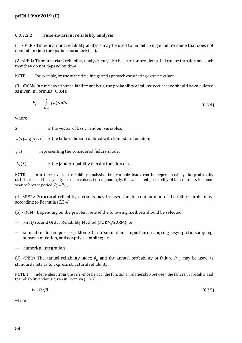
prEN 1990:2019 (E)
84
C.3.3.2.2 Time-invariant reliability analysis
(1) <PER> Time-invariant reliability analysis may be used to model a single failure mode that does not depend on time (or spatial characteristics).
(2) <PER> Time-invariant reliability analysis may also be used for problems that can be transformed such that they do not depend on time.
NOTE For example, by use of the time-integrated approach considering extreme values.
(3) <RCM> In time-invariant reliability analysis, the probability of failure occurrence should be calculated as given in Formula (C.3.4):
( )
( )fP f d
= X
x
x x (C.3.4)
where
x is the vector of basic random variables;
( ) ( ) 0g = x x is the failure domain defined with limit state function;
( )g x representing the considered failure mode;
( )fX x is the joint probability density function of x.
NOTE In a time-invariant reliability analysis, time-variable loads can be represented by the probability distributions of their yearly extreme values. Correspondingly, the calculated probability of failure refers to a one-
year reference period ,1f f yP P= .
(4) <PER> Structural reliability methods may be used for the computation of the failure probability, according to Formula (C.3.4).
(5) <RCM> Depending on the problem, one of the following methods should be selected:
— First/Second Order Reliability Method (FORM/SORM); or
— simulation techniques, e.g. Monte Carlo simulation, importance sampling, asymptotic sampling, subset simulation, and adaptive sampling; or
— numerical integration.
(6) <PER> The annual reliability index βa and the annual probability of failure Pf,a may be used as
standard metrics to express structural reliability.
NOTE 1 Independent from the reference period, the functional relationship between the failure probability and the reliability index is given in Formula (C.3.5):
( )fP = − (C.3.5)
where
prEN 1990:2019 (E)
85
( ). is the standard normal cumulative probability distribution function.
NOTE 2 Numerical values of β for indicative values of Pf are given in Table C.3.1.
Table C.3.1 — Relation between Pf and β
fP 10-1 10-2 10-3 10-4 10-5 10-6 10-7
( )1
fP −= − 1,28 2,33 3,09 3,72 4,26 4,75 5,20
C.3.3.2.3 Time-variant reliability analysis
(1) <RCM> A time-variant reliability analysis should be used when a single failure mechanism is being analyzed and its occurrence probability does depend on the point in time.
C.3.4 Reliability requirements
C.3.4.1 General
(1) <REQ> Reliability requirements shall be as prescribed by the relevant national authority.
NOTE 1 In the partial factor method, reliability requirements are implicitly satisfied through the use of partial factors specified in the Eurocodes.
NOTE 2 The following clauses are addressed to the relevant national authorities to assist them define the reliability requirements.
(2) <POS> Reliability requirements can be established by a risk assessment.
(3) <POS> Reliability requirements can be formulated in terms of minimum reliability requirements and/or service life cost optimal target reliability requirements:
— the minimum reliability requirements depend on the societal capacity and preferences to invest into life safety (minimum reliability requirements are normally compulsory);
— Target reliability requirements depend on the expected failure consequences and on all costs associated with the design, operation, inspection, maintenance and renewal of structures over the time period for which they are needed.
(4) <REQ> Reliability requirements shall be fulfilled for all relevant failure events including single member failure, partial structural failure, and full structural-system collapse.
NOTE 1 The specified reliability requirements relevant for ultimate and serviceability limit state design do not account for human errors. Therefore, failure probabilities are not directly related to the observed failure rates, which are highly influenced by failures involving some effects of human errors.
NOTE 2 Requirements to minimize, detect and mitigate human errors are given in Annex B.
prEN 1990:2019 (E)
86
(5) <PER> Explicit reliability requirements may be used to:
— establish criteria for the reliability based design and assessment;
— support design assisted by testing;
— facilitate the calibration of partial safety factor design formats.
NOTE For the first two cases, the requirements are relevant to the designer. For the last case, the requirements are relevant to the relevant national authorities, see Annex C.4.
C.3.4.2 Criterion for reliability based design and assessment
(1) <RCM> If the design situation can be directly related to a similar reference design situation that is covered by the partial safety factor design format, it should be demonstrated that the same reliability level as the reference design is obtained.
NOTE This relative comparison should be made based on similar probabilistic models.
(2) <RCM> When it is stated in the Eurocodes that a design and assessment situation is not covered by the partial safety factor design format, target reliability values should be defined.
NOTE Table C.3.2 gives the target values β for the 50 years reference period assumed within this standard for non-seismic design situations for structures included in the scope of Annexes A.1 and A.2. Different target reliability values β for different reference periods can be set by the National Annex for use in a country.
Table C.3.2 (NDP) — Target values for reliability index β for different consequence classes (for non-seismic ultimate limit state) relevant to structures in the scope of Annexes A.1 and A.2
Consequence class
β (50 years reference period)
CC3 4,3 CC2 3,8 CC1 3,3
C.3.4.3 Reliability requirements for reliability-based code calibration
(1) <RCM> For the purpose of code calibration of partial safety factors and other reliability elements in semi-probabilistic safety formats, the reliability requirement should be defined as a target value for reliability levels, taken as representative averages over the considered design situations.
NOTE Code calibration is performed by national competent authorities.
(2) <RCM> If the partial factor design format that is being calibrated can be related to an existing partial factor design format for which the safety level is considered satisfactory, the corresponding average reliability level should be used as a target value for calibration.
(3) <RCM> If the partial factor design format being calibrated cannot be related to an existing design format, the reliability targets specified in C.3.4.2(2) should be used.
prEN 1990:2019 (E)
87
C.3.4.4 Reliability requirements for design assisted by testing
(1) <RCM> The reliability level to be used for the determination of design values based on data from tests or observations based on D.8.2 should correspond to a one-year reference period and should be chosen as specified in C.3.4.2(2).
C.4 Approach for calibration of design values
C.4.1 Reliability requirements for reliability-based code calibration
(1) <RCM> For the purpose of code calibration of partial safety factors and other reliability elements in semi-probabilistic safety formats, the reliability requirement should be defined as a target value.
(2) <PER> When the reliability of a representative set of comparable structures designed according to existing codes is considered satisfactory, target value of the reliability level for structures similar to those included in this set may be derived from the reliability assessment of this set.
NOTE Comparable structures means that they are made with the same material and have similar destinations, similar structural schemes and design dominated by the same actions.
(3) <RCM> As the numerical values of the reliability depend on the structure layout, on the material and on the limit state equation as well as on the assumed statistical properties of the relevant variables, code calibration of partial safety factors should be performed according the same assumptions as adopted in the definition of target values.
NOTE Probabilistic models for loads and resistances are given in the technical report.
(4) <PER> The reliability targets specified according to C.3.4.2(2) may be used.
C.4.2 Partial factor design format and code parameters
(1) <PER> The principle form of the design formula (Formula (8.1)) may be rearranged as given in Formula (C.4.1):
0d dR E− (C.4.1)
where the design values for the load bearing capacity Rd and the effect of action Ed are obtained from
Formulae (C.4.2) and (C.4.3):
( ; ; ; )d dR R= dd d d,RX a θ F (C.4.2)
( ; ; ; )d dE E= dd d d,EF a θ X (C.4.3)
where
dF are vectors of design values of actions independent on the material properties;
d,RF are vectors of design values of actions depending on the material properties, when relevant;
𝑿𝑑 are vectors of design values of material properties independent on the combination of actions;
prEN 1990:2019 (E)
88
𝑿𝑑 are vectors of design values of material properties depending on the combination of actions, when relevant;
da is a vector of design values of geometrical properties;
dθ is a vector of design values of model uncertainties.
NOTE Formulae (C.4.1) to (C.4.3) are applicable for time-invariant reliability problems represented by linear limit state functions with independent variables, see 8.2.1. For some particular design situations (e.g. fatigue, geotechnics) a more general formulation may be necessary to express a limit state.
C.4.3 Partial factors
(1) <RCM> Partial safety factors for actions, γF, and for resistance, γM, should include model uncertainties.
(2) <PER> The design value of a basic variable related to loads (Fd) may be defined as the multiplication
of the characteristic value Fk by a corresponding partial safety factor γF (i.e. Fd = γFFk).
(3) <PER> The design value of a basic variable related to resistance (Xd) may be defined as the division
of the characteristic value Xk by a corresponding partial safety factor γM (i.e. Xd = Xk / γM).
NOTE More specific formats for the determination of design values for actions and resistances are given in Clause 8.
(4) <PER> When model uncertainties are considered separately, partial safety factors may be derived from Formula (C.4.4) or Formula (C.4.5):
𝛾𝐹 = 𝛾𝑆𝑑𝛾𝑓 (C.4.4)
𝛾𝑀 = 𝛾𝑅𝑑𝛾𝑚 (C.4.5)
where
γf covers uncertainty in representative values of actions;
γSd covers the model uncertainty in actions and action effects;
γm covers uncertainty in basic variables describing the resistance;
γRd covers the model uncertainty in structural resistance, also accounting, when relevant, the bias
in resistance model, see Annex D.
(5) <PER> The characteristic value Yk may be taken as a specified p-fractile value from the statistical
distribution FY chosen to represent the basic variable, as given in Formula (C.4.6):
( )1
k YY F p−= (C.4.6)
where
prEN 1990:2019 (E)
89
FY is the cumulative probability distribution function of the basic variable Y.
NOTE Typical values for p are:
— resistance related variables: p = 0,05;
— permanent actions: p = 0,5;
— time-variable actions: p = 0,98, referring to the distribution of the yearly extreme values.
(6) <RCM> The partial safety factors for the various actions and materials characteristics entering the design formulae should be determined by calibration to satisfy Formula (C.4.1) and be consistent with the reliability requirements.
C.4.4 Basis for calibration of design values
C.4.4.1 General
(1) <PER> The design value method, see C.4.4.2, may be used to determine partial safety factors.
(2) <PER> For the calibration of design formats that cover a multitude of design situations the guidelines in C.4.5 may be followed.
C.4.4.2 The design value method
(1) <PER> For simple cases, a direct correspondence between the design value and the reliability requirements may be established by the so-called ‘design value method’ in Formula (C.4.7):
( )( )1
Y YdY F −= − (C.4.7)
where
dY is the design value;
YF is the cumulative probability distribution function of the basic variable Y;
Y with 1Y ) is a sensitivity factor indicating the importance of Y in the reliability estimation;
β = βtgt is the target value for the 50 year reliability index according to the reliability requirement in C.3.4.
(2) <PER> Design values Yd and characteristic values Yk for some common distributions may be
determined according Table C.4.1.
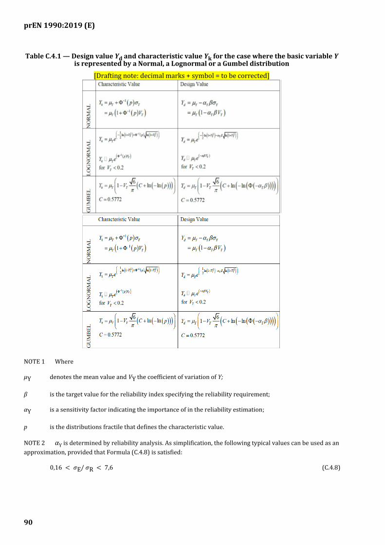
prEN 1990:2019 (E)
90
Table C.4.1 — Design value Yd and characteristic value Yk for the case where the basic variable Y is represented by a Normal, a Lognormal or a Gumbel distribution
[Drafting note: decimal marks + symbol = to be corrected]
NOTE 1 Where
μY denotes the mean value and VY the coefficient of variation of Y;
β is the target value for the reliability index specifying the reliability requirement;
αY is a sensitivity factor indicating the importance of in the reliability estimation;
p is the distributions fractile that defines the characteristic value.
NOTE 2 αY is determined by reliability analysis. As simplification, the following typical values can be used as an
approximation, provided that Formula (C.4.8) is satisfied:
0,16 < 𝜎E/ 𝜎R < 7,6 (C.4.8)
prEN 1990:2019 (E)
91
where
— if Y represents a strength related variable: αY = 0,8;
— if Y represents a leading load related variable: αY = -0,7;
— If Y is dominating the reliability problem: αY = 1 (resistance); αY = -1 (load).
NOTE 3 Self-weight is usually represented by a Normal distribution; Resistance variables are often represented by a Lognormal distribution; the extreme values per reference period of time-variable actions are represented by the Gumbel distribution.
(3) <RCM> When the action model contains several basic variables, Formula (C.4.5) should be used for the leading variable only. For the accompanying actions the design values can be defined by Formula (C.4.9):
𝑃 (𝐸 > 𝐸_d) = 𝛷 (−0,4x0,7x𝛽) = 𝛷(−0,28𝛽) (C.4.9)
(4) The target value for the reliability index and the extreme value distribution used to represent time-
variable actions are defined based on the same reference period, i.e. with β = βtgt the reference period is 50 years, with 𝛽 = 𝛽𝑞𝑦
𝑡𝑔𝑡 the reference period is one year.
C.4.4.3 Code optimization
(1) <RCM> The reliability elements, including partial factors γ and combination factors Ψ, should be
calibrated in such a way that the target reliability index βtgt, chosen according to C.3.4.2, is best achieved.
NOTE 1 The calibration procedure given in Figure C.4.1, involves the following steps:
— selecting of a set of comparable reference structures;
— selecting and specifying a set of reliability elements, e.g. partial factors, Ψ factors;
— designing the structures according to the selected set of reliability elements;
— calculating the reliability indices βi for the designed structures;
— calculating the difference: 𝐷 = ∑ 𝑤𝑖𝑖 (𝛽𝑖 − 𝛽𝑡𝑔𝑡)2where wi is the weight factor i;
— repeating steps to minimize D.
NOTE 2 A more detailed procedure how to provide this optimisation is described in several sources, e.g. in ISO 2394.
C.4.5 Combination of variable actions
(1) <RCM> When two or more time-varying loads act simultaneously on a structure, its combination should be considered.
NOTE 1 In the semi-probabilistic design format, load combination is accounted by the load reduction factors Ψ0
which are calibrated considering the statistical properties of the processes.
NOTE 2 Table C.4.2 gives formulae for obtaining the factors Ψ0 in the case of two variable actions.
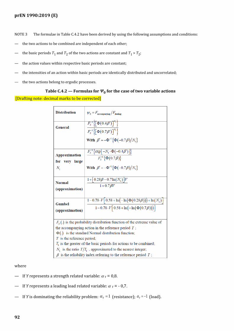
prEN 1990:2019 (E)
92
NOTE 3 The formulae in Table C.4.2 have been derived by using the following assumptions and conditions:
— the two actions to be combined are independent of each other;
— the basic periods T1 and T2 of the two actions are constant and T1 > T2;
— the action values within respective basic periods are constant;
— the intensities of an action within basic periods are identically distributed and uncorrelated;
— the two actions belong to ergodic processes.
Table C.4.2 — Formulas for Ψ0 for the case of two variable actions
[Drafting note: decimal marks to be corrected]
where
— If Y represents a strength related variable: Y = 0,8.
— If Y represents a leading load related variable: Y = - 0,7.
— If Y is dominating the reliability problem: 1Y = (resistance); 1Y = − (load).

prEN 1990:2019 (E)
93
NOTE 4 Self-weight is usually represented by a Normal distribution; Resistance variables are often represented by a Lognormal distribution; the extreme values per reference period of time-variable actions are represented by the Gumbel distribution.
(2) <RCM> The target value for the reliability index and the extreme value distribution used to represent time-variable actions should be defined based on the same reference period, i.e. with
1
tgt
y = the
reference period is one year.

prEN 1990:2019 (E)
94
(informative)
Design assisted by testing
D.1 Use of this informative Annex
(1) This informative Annex provides additional guidance to that given in 7.3, on design assisted by testing.
NOTE National choice on the application of this Informative Annex is given in the National Annex. If the National Annex contains no information on the application of this informative annex, it can be used.
D.2 Scope and field of application
(1) This Annex gives guidance on the procedure to be followed to directly determine by testing either the resistance-side parameters of the design equation or structures that lead to a reliability level not less than that required by this document.
NOTE 1 Tests may be carried out to determine the representative or design values of actions, relations between actions and actions effects and, directly, the reliability of structures. Statistical considerations and analyses necessary for these, which can depend on the type of action, i.e. waves, currents, wind and friction/drag forces, etc., can be found in the relevant EN1991 parts or in specialist literature.
NOTE 2 This Annex covers statistical uncertainties involved in converting test measurements to representative or design values. Where direct measurement of the parameter of interest is either not possible or not carried out, it is required to convert the measurements via models. Uncertainty in these models, called ‘model uncertainty’, needs to be considered and may be incorporated in the coefficient of variation. For details, specialist literature may be consulted.
NOTE 3 The methods given in this Annex do not cover testing of geotechnical materials for which EN 1997 should be consulted.
NOTE 4 The application of reliability requirements for design assisted by testing should be in accordance with the legal system in force in each country.
(2) This Annex provides guidance on the application of 7.3(3), 8.1(3), and 8.3.6(2).
NOTE This Annex is not intended to replace acceptance rules given in harmonised European product specifications, other product specifications or execution standards.
D.3 Symbols
In this Annex, the following symbols apply.
D.3.1 Latin upper-case letters
E(.) Mean value of (.)
V Coefficient of variation, V = (standard deviation)/(mean value)
VX Coefficient of variation of X
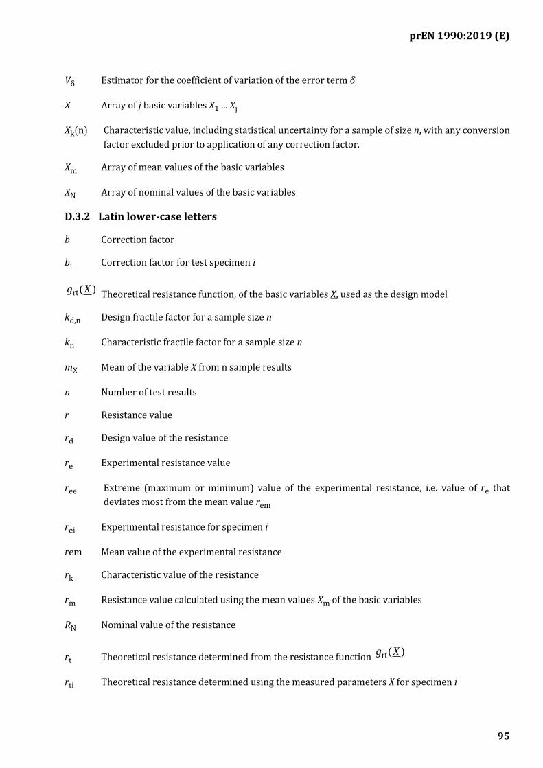
prEN 1990:2019 (E)
95
Vδ Estimator for the coefficient of variation of the error term δ
X Array of j basic variables X1 ... Xj
Xk(n) Characteristic value, including statistical uncertainty for a sample of size n, with any conversion
factor excluded prior to application of any correction factor.
Xm Array of mean values of the basic variables
XN Array of nominal values of the basic variables
D.3.2 Latin lower-case letters
b Correction factor
bi Correction factor for test specimen i
)(rt Xg Theoretical resistance function, of the basic variables X, used as the design model
kd,n Design fractile factor for a sample size n
kn Characteristic fractile factor for a sample size n
mX Mean of the variable X from n sample results
n Number of test results
r Resistance value
rd Design value of the resistance
re Experimental resistance value
ree Extreme (maximum or minimum) value of the experimental resistance, i.e. value of re that
deviates most from the mean value rem
rei Experimental resistance for specimen i
rem Mean value of the experimental resistance
rk Characteristic value of the resistance
rm Resistance value calculated using the mean values Xm of the basic variables
RN Nominal value of the resistance
rt Theoretical resistance determined from the resistance function )(rt Xg
rti Theoretical resistance determined using the measured parameters X for specimen i
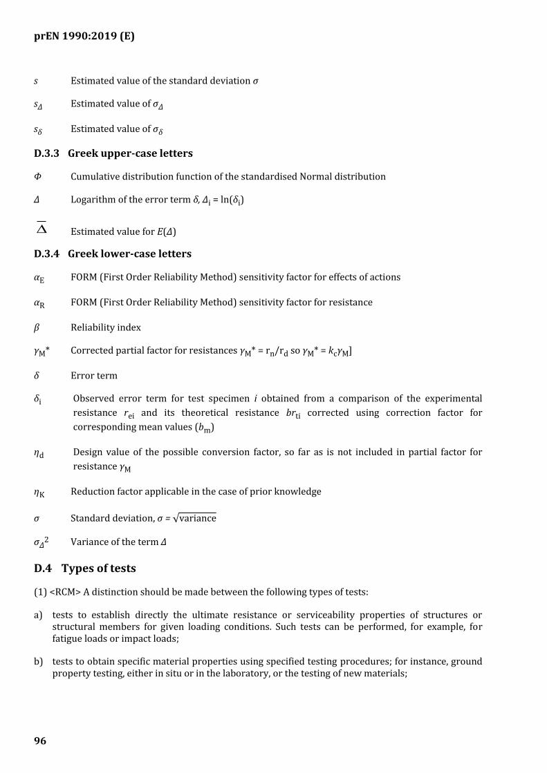
prEN 1990:2019 (E)
96
s Estimated value of the standard deviation σ
sΔ Estimated value of σΔ
sδ Estimated value of σδ
D.3.3 Greek upper-case letters
Φ Cumulative distribution function of the standardised Normal distribution
Δ Logarithm of the error term δ, Δi = ln(δi)
Estimated value for E(Δ)
D.3.4 Greek lower-case letters
αE FORM (First Order Reliability Method) sensitivity factor for effects of actions
αR FORM (First Order Reliability Method) sensitivity factor for resistance
β Reliability index
γM* Corrected partial factor for resistances γM* = rn/rd so γM* = kcγM]
δ Error term
δi Observed error term for test specimen i obtained from a comparison of the experimental
resistance rei and its theoretical resistance brti corrected using correction factor for
corresponding mean values (bm)
ηd Design value of the possible conversion factor, so far as is not included in partial factor for
resistance γM
ηK Reduction factor applicable in the case of prior knowledge
σ Standard deviation, σ = √variance
σΔ2 Variance of the term Δ
D.4 Types of tests
(1) <RCM> A distinction should be made between the following types of tests:
a) tests to establish directly the ultimate resistance or serviceability properties of structures or structural members for given loading conditions. Such tests can be performed, for example, for fatigue loads or impact loads;
b) tests to obtain specific material properties using specified testing procedures; for instance, ground property testing, either in situ or in the laboratory, or the testing of new materials;
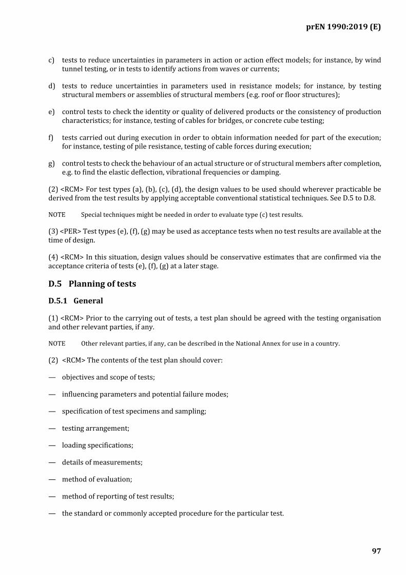
prEN 1990:2019 (E)
97
c) tests to reduce uncertainties in parameters in action or action effect models; for instance, by wind tunnel testing, or in tests to identify actions from waves or currents;
d) tests to reduce uncertainties in parameters used in resistance models; for instance, by testing structural members or assemblies of structural members (e.g. roof or floor structures);
e) control tests to check the identity or quality of delivered products or the consistency of production characteristics; for instance, testing of cables for bridges, or concrete cube testing;
f) tests carried out during execution in order to obtain information needed for part of the execution; for instance, testing of pile resistance, testing of cable forces during execution;
g) control tests to check the behaviour of an actual structure or of structural members after completion, e.g. to find the elastic deflection, vibrational frequencies or damping.
(2) <RCM> For test types (a), (b), (c), (d), the design values to be used should wherever practicable be derived from the test results by applying acceptable conventional statistical techniques. See D.5 to D.8.
NOTE Special techniques might be needed in order to evaluate type (c) test results.
(3) <PER> Test types (e), (f), (g) may be used as acceptance tests when no test results are available at the time of design.
(4) <RCM> In this situation, design values should be conservative estimates that are confirmed via the acceptance criteria of tests (e), (f), (g) at a later stage.
D.5 Planning of tests
D.5.1 General
(1) <RCM> Prior to the carrying out of tests, a test plan should be agreed with the testing organisation and other relevant parties, if any.
NOTE Other relevant parties, if any, can be described in the National Annex for use in a country.
(2) <RCM> The contents of the test plan should cover:
— objectives and scope of tests;
— influencing parameters and potential failure modes;
— specification of test specimens and sampling;
— testing arrangement;
— loading specifications;
— details of measurements;
— method of evaluation;
— method of reporting of test results;
— the standard or commonly accepted procedure for the particular test.
prEN 1990:2019 (E)
98
D.5.2 Objectives and scope
(1) <RCM> The objective of the tests should be clearly stated and should include aspects mentioned in D.5.1. In addition, the parameters to be varied during the test and the intended range of validity of the test results should be described. Limitations of the test and required conversions, e.g. scaling effects, should be specified.
D.5.3 Influencing parameters and potential failure modes
(1) <RCM> All properties and circumstances that can influence the results of the tests performed to check the theoretical predictions should be taken into account, including:
— geometrical parameters and their variability;
— geometrical imperfections;
— material properties;
— parameters influenced by fabrication and execution procedures;
— ambient environmental conditions;
— scale effects;
— relevant, any sequencing related to fabrication and testing.
(2) <RCM> The expected modes of failure and/or calculation models, together with the corresponding variables should be described. If more than one failure mode might be critical, then the test plan should be preceded by pilot tests intended to identify the critical one.
NOTE Attention needs to be given to the fact that a structural member can possess several different failure modes.
D.5.4 Specification of test specimens and sampling
(1) <RCM> Test specimens should be specified, or obtained by sampling, in such a way as to represent the conditions of the real structure.
NOTE Factors to be taken into account include:
— dimensions and tolerances;
— material and fabrication of prototypes;
— number of test specimens;
— sampling procedures;
— restraints.
(2) <RCM> The objective of the sampling procedure should be to obtain a statistically representative sample.
(3) <RCM> Any differences between the test specimens and the product population that could influence the test results should be noted and considered.
prEN 1990:2019 (E)
99
D.5.5 Testing arrangement
(1) <RCM> The test equipment should be relevant for the type of tests and the expected range of measurements. Special attention should be given to measures to obtain sufficient strength and stiffness of the loading and supporting rigs, and clearance for deflections, etc.
D.5.6 Loading specifications
(1) <RCM> The loading and environmental conditions to be specified for the test should include:
— loading points;
— loading history;
— restraints;
— temperatures;
— relative humidity;
— loading by deformation or force control, etc.
(2) <RCM> Load sequencing should be selected to represent the anticipated use of the structural member, under both normal and severe conditions of use. Interactions between the structural response and the apparatus used to apply the load should be taken into account where relevant.
(3) <RCM> Where structural behaviour depends upon the effects of one or more actions that do not be vary systematically, then those actions or effects should be specified by their representative values.
D.5.7 Details of measurements
(1) <RCM> Prior to the testing, all relevant properties to be measured for each individual test specimen should be listed.
(2) <RCM> Additionally, a list should be made of:
— measurement-locations,
— of procedures for recording results, including if relevant:
— time histories of displacements;
— velocities;
— accelerations;
— strains;
— forces and pressures;
— frequency of measurement;
— accuracy of measurements;
— appropriate measuring devices.
prEN 1990:2019 (E)
100
(3) <RCM> Measurement devices should be calibrated prior to tests, be sufficiently sensitive to the data being acquired and provide sufficient accuracy.
(4) <RCM> The data acquisition system should be able to record all data at the required frequency.
D.5.8 Method of evaluation
NOTE For specific guidance, see D.6 to D.9.
D.5.9 Method of reporting test results
(1) <RCM> Any standards on which the tests are based should be reported.
(2) <RCM> Where agreed with relevant parties, sufficient data that could enable an independent assessment should be provided within the report.
(3) <RCM> The results presented should demonstrate the achievement of the objectives of the tests.
D.6 Derivation of characteristic or design values
(1) <RCM> The derivation from tests of the design values for a material property, a model parameter or a resistance should be carried out according to one of the following methods:
— Method A: by assessing a characteristic value, which is then divided by a partial factor and possibly multiplied if necessary by an explicit conversion factor, see D.8.2 and D.9.2; or
— Method B: by direct determination of the design value, implicitly or explicitly accounting for the conversion of results and the total reliability required, see D.8.3 and D.9.3.
NOTE In general, method a) is preferred provided the value of the partial factor is determined from the normal design procedure, see (3).
(2) <RCM> The derivation of a characteristic value using Method A should take into account:
— the scatter of test data;
— statistical uncertainty associated with the number of tests;
— prior statistical knowledge.
(3) <RCM> The partial factor to be applied to a characteristic value should be taken from the appropriate Eurocode provided there is sufficient similarity between the tests and the usual field of application of the partial factor as used in numerical verifications.
(4) <RCM> If the response of the structure or structural member or the resistance of the material depends on influences not sufficiently covered by the tests such as:
— time and duration effects;
— scale and size effects;
— different environmental, loading and boundary conditions;
— resistance effects;
prEN 1990:2019 (E)
101
then the calculation model should take such influences into account, as appropriate.
(5) <RCM> Where method B is used, the following should be taken into account when determining design values:
— the relevant limit states;
— the required level of reliability;
— compatibility with the assumptions relevant to the actions side;
— where appropriate, the required design service life;
— prior knowledge from similar situations.
NOTE Further information may be found in D.7, D.8 and D.9.
D.7 General principles for statistical evaluations
(1) <RCM> When evaluating test results, the behaviour of test specimens and failure modes should be compared with theoretical predictions and previous similar experience.
(2) <RCM> If significant deviations from a prediction occur, an explanation should be sought and additional testing under different conditions, or modification of the theoretical model, should be considered.
(3) <RCM> The evaluation of test results should be based on statistical methods, with the use of available (statistical) information about the type of distribution to be used and its associated parameters.
(4) <PER> The methods given in this Annex may be used when the following conditions are satisfied:
— the statistical data (including prior information) are taken from identified populations which are sufficiently homogeneous;
— a sufficient number of observations is available.
NOTE At the level of interpretation of tests results, three main categories can be distinguished:
— Where one test only, or very few tests, is/are performed, no classical statistical interpretation is possible. Only the use of extensive prior information, associated with hypotheses about the relative degrees of importance of this information and of the test results, makes it possible to present a statistical interpretation using Bayesian procedures, see ISO 12491;
— If a larger series of tests is performed to evaluate a parameter, a classical statistical interpretation might be possible. The commoner cases are treated, as examples, in D.7. This interpretation still needs to use some prior information about the parameter; however, the amount of information required is normally less than for the previous situation;
— When a series of tests is carried out in order to calibrate a model, as described in terms of a function, and one or more associated parameters, a classical statistical interpretation is possible.
(5) <RCM> The result of a test evaluation should be considered valid only for the specifications and load characteristics considered in the tests.
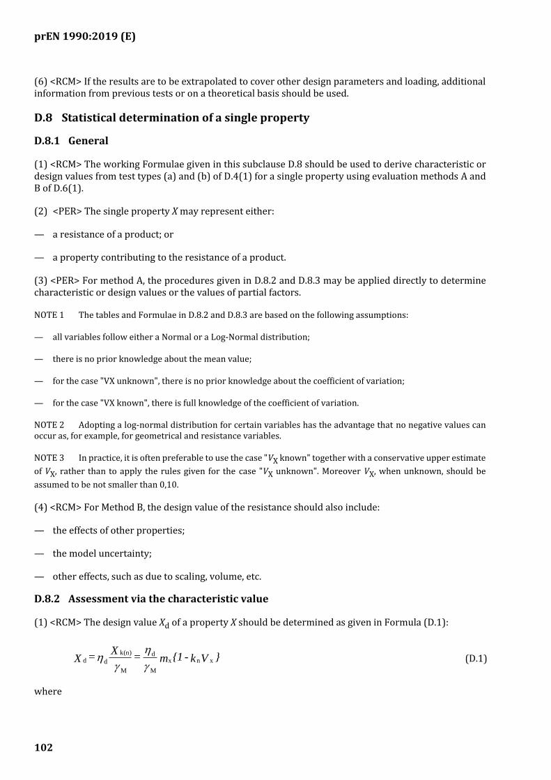
prEN 1990:2019 (E)
102
(6) <RCM> If the results are to be extrapolated to cover other design parameters and loading, additional information from previous tests or on a theoretical basis should be used.
D.8 Statistical determination of a single property
D.8.1 General
(1) <RCM> The working Formulae given in this subclause D.8 should be used to derive characteristic or design values from test types (a) and (b) of D.4(1) for a single property using evaluation methods A and B of D.6(1).
(2) <PER> The single property X may represent either:
— a resistance of a product; or
— a property contributing to the resistance of a product.
(3) <PER> For method A, the procedures given in D.8.2 and D.8.3 may be applied directly to determine characteristic or design values or the values of partial factors.
NOTE 1 The tables and Formulae in D.8.2 and D.8.3 are based on the following assumptions:
— all variables follow either a Normal or a Log-Normal distribution;
— there is no prior knowledge about the mean value;
— for the case "VX unknown", there is no prior knowledge about the coefficient of variation;
— for the case "VX known", there is full knowledge of the coefficient of variation.
NOTE 2 Adopting a log-normal distribution for certain variables has the advantage that no negative values can occur as, for example, for geometrical and resistance variables.
NOTE 3 In practice, it is often preferable to use the case "VX known" together with a conservative upper estimate
of VX, rather than to apply the rules given for the case "VX unknown". Moreover VX, when unknown, should be
assumed to be not smaller than 0,10.
(4) <RCM> For Method B, the design value of the resistance should also include:
— the effects of other properties;
— the model uncertainty;
— other effects, such as due to scaling, volume, etc.
D.8.2 Assessment via the characteristic value
(1) <RCM> The design value Xd of a property X should be determined as given in Formula (D.1):
}Vk - {1m = X
= X xnx
M
d
M
k(n)
dd
(D.1)
where
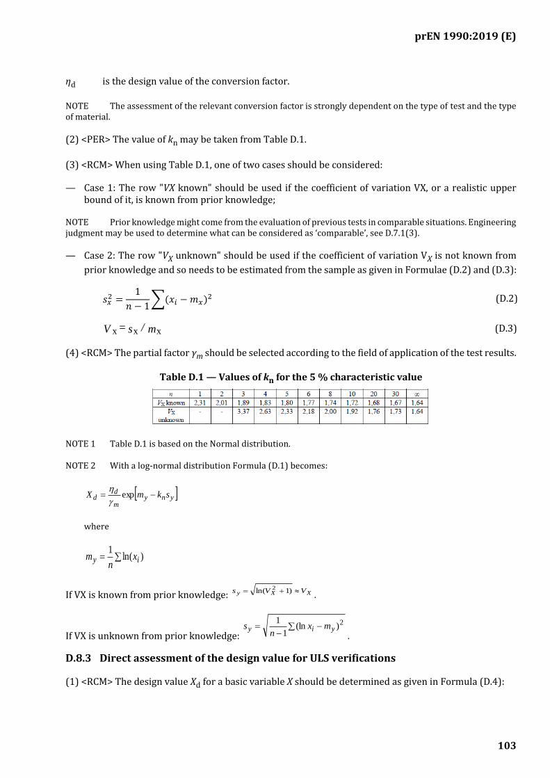
prEN 1990:2019 (E)
103
ηd is the design value of the conversion factor.
NOTE The assessment of the relevant conversion factor is strongly dependent on the type of test and the type of material.
(2) <PER> The value of kn may be taken from Table D.1.
(3) <RCM> When using Table D.1, one of two cases should be considered:
— Case 1: The row "VX known" should be used if the coefficient of variation VX, or a realistic upper bound of it, is known from prior knowledge;
NOTE Prior knowledge might come from the evaluation of previous tests in comparable situations. Engineering judgment may be used to determine what can be considered as ‘comparable’, see D.7.1(3).
— Case 2: The row "VX unknown" should be used if the coefficient of variation VX is not known from
prior knowledge and so needs to be estimated from the sample as given in Formulae (D.2) and (D.3):
𝑠𝑥2 =
1
𝑛 − 1∑(𝑥𝑖 −𝑚𝑥)
2 (D.2)
m / s = V xxx (D.3)
(4) <RCM> The partial factor γm should be selected according to the field of application of the test results.
Table D.1 — Values of kn for the 5 % characteristic value
NOTE 1 Table D.1 is based on the Normal distribution.
NOTE 2 With a log-normal distribution Formula (D.1) becomes:
ynym
dd skmX −= exp
where
= )ln(1
iy xn
m
If VX is known from prior knowledge: XXy VVs += )1ln( 2
.
If VX is unknown from prior knowledge: −
−= 2)(ln
1
1yiy mx
ns
.
D.8.3 Direct assessment of the design value for ULS verifications
(1) <RCM> The design value Xd for a basic variable X should be determined as given in Formula (D.4):
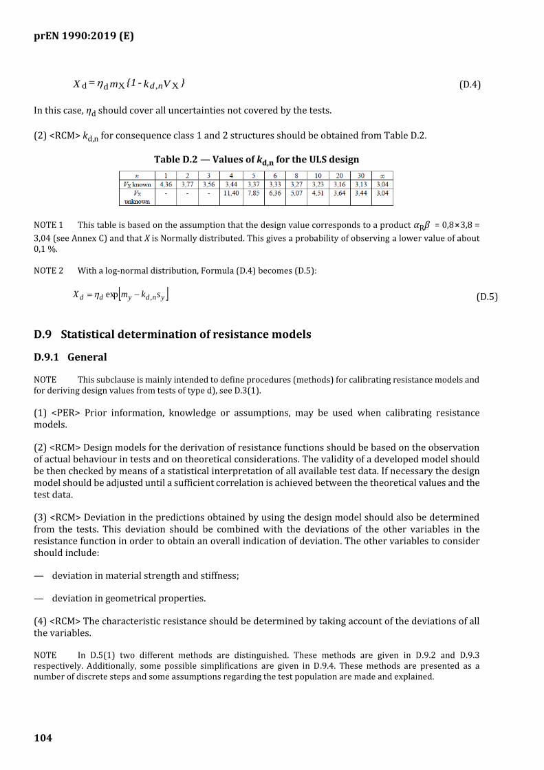
prEN 1990:2019 (E)
104
}Vk - {1 m = X nd X,Xdd (D.4)
In this case, ηd should cover all uncertainties not covered by the tests.
(2) <RCM> kd,n for consequence class 1 and 2 structures should be obtained from Table D.2.
Table D.2 — Values of kd,n for the ULS design
NOTE 1 This table is based on the assumption that the design value corresponds to a product αRβ = 0,8⨯3,8 =
3,04 (see Annex C) and that X is Normally distributed. This gives a probability of observing a lower value of about 0,1 %.
NOTE 2 With a log-normal distribution, Formula (D.4) becomes (D.5):
yndydd skmX ,exp −= (D.5)
D.9 Statistical determination of resistance models
D.9.1 General
NOTE This subclause is mainly intended to define procedures (methods) for calibrating resistance models and for deriving design values from tests of type d), see D.3(1).
(1) <PER> Prior information, knowledge or assumptions, may be used when calibrating resistance models.
(2) <RCM> Design models for the derivation of resistance functions should be based on the observation of actual behaviour in tests and on theoretical considerations. The validity of a developed model should be then checked by means of a statistical interpretation of all available test data. If necessary the design model should be adjusted until a sufficient correlation is achieved between the theoretical values and the test data.
(3) <RCM> Deviation in the predictions obtained by using the design model should also be determined from the tests. This deviation should be combined with the deviations of the other variables in the resistance function in order to obtain an overall indication of deviation. The other variables to consider should include:
— deviation in material strength and stiffness;
— deviation in geometrical properties.
(4) <RCM> The characteristic resistance should be determined by taking account of the deviations of all the variables.
NOTE In D.5(1) two different methods are distinguished. These methods are given in D.9.2 and D.9.3 respectively. Additionally, some possible simplifications are given in D.9.4. These methods are presented as a number of discrete steps and some assumptions regarding the test population are made and explained.
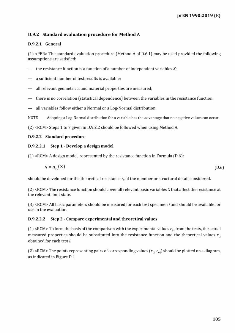
prEN 1990:2019 (E)
105
D.9.2 Standard evaluation procedure for Method A
D.9.2.1 General
(1) <PER> The standard evaluation procedure (Method A of D.6.1) may be used provided the following assumptions are satisfied:
— the resistance function is a function of a number of independent variables X;
— a sufficient number of test results is available;
— all relevant geometrical and material properties are measured;
— there is no correlation (statistical dependence) between the variables in the resistance function;
— all variables follow either a Normal or a Log-Normal distribution.
NOTE Adopting a Log-Normal distribution for a variable has the advantage that no negative values can occur.
(2) <RCM> Steps 1 to 7 given in D.9.2.2 should be followed when using Method A.
D.9.2.2 Standard procedure
D.9.2.2.1 Step 1 - Develop a design model
(1) <RCM> A design model, represented by the resistance function in Formula (D.6):
( )Xrtgrt = (D.6)
should be developed for the theoretical resistance rt of the member or structural detail considered.
(2) <RCM> The resistance function should cover all relevant basic variables X that affect the resistance at the relevant limit state.
(3) <RCM> All basic parameters should be measured for each test specimen i and should be available for use in the evaluation.
D.9.2.2.2 Step 2 - Compare experimental and theoretical values
(1) <RCM> To form the basis of the comparison with the experimental values rei from the tests, the actual
measured properties should be substituted into the resistance function and the theoretical values rti
obtained for each test i.
(2) <RCM> The points representing pairs of corresponding values (rti, rei) should be plotted on a diagram,
as indicated in Figure D.1.
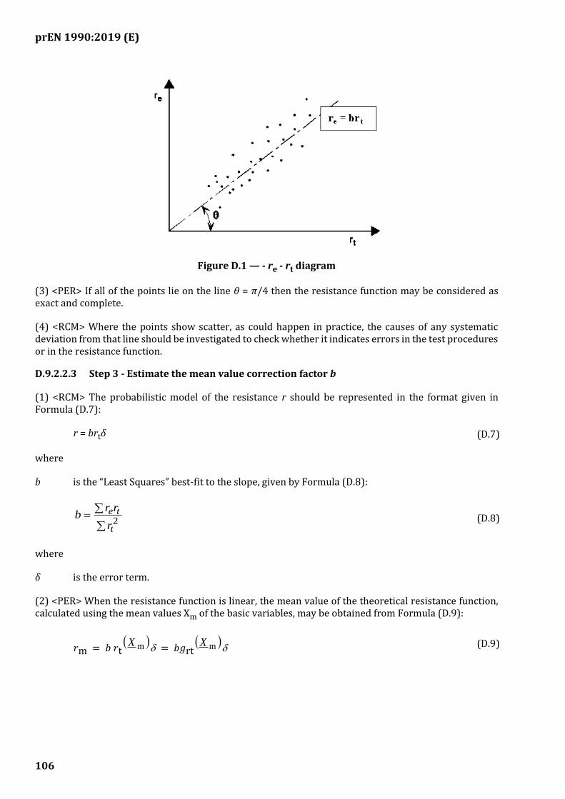
prEN 1990:2019 (E)
106
Figure D.1 — - re - rt diagram
(3) <PER> If all of the points lie on the line θ = π/4 then the resistance function may be considered as exact and complete.
(4) <RCM> Where the points show scatter, as could happen in practice, the causes of any systematic deviation from that line should be investigated to check whether it indicates errors in the test procedures or in the resistance function.
D.9.2.2.3 Step 3 - Estimate the mean value correction factor b
(1) <RCM> The probabilistic model of the resistance r should be represented in the format given in Formula (D.7):
r = brtδ (D.7)
where
b is the “Least Squares” best-fit to the slope, given by Formula (D.8):
=
2t
te
r
rrb
(D.8)
where
δ is the error term.
(2) <PER> When the resistance function is linear, the mean value of the theoretical resistance function, calculated using the mean values Xm of the basic variables, may be obtained from Formula (D.9):
𝑟m = 𝑏 𝑟t( )mX
= 𝑏𝑔rt( )mX
(D.9)
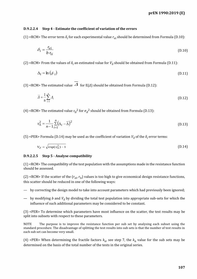
prEN 1990:2019 (E)
107
D.9.2.2.4 Step 4 - Estimate the coefficient of variation of the errors
(1) <RCM> The error term δi for each experimental value rei should be determined from Formula (D.10):
ti
eii
r b
r=
(D.10)
(2) <RCM> From the values of δi an estimated value for Vδ should be obtained from Formula (D.11):
( ) i i ln = (D.11)
(3) <RCM> The estimated value for E(Δ) should be obtained from Formula (D.12):
=
=n
1i
in
1
(D.12)
(4) <RCM> The estimated value sΔ2 for σΔ
2 should be obtained from Formula (D.13):
( ) −−
==
n
iin
s1
22
1
1
(D.13)
(5) <PER> Formula (D.14) may be used as the coefficient of variation Vδ of the δi error terms:
1)exp( 2 −= sV (D.14)
D.9.2.2.5 Step 5 - Analyse compatibility
(1) <RCM> The compatibility of the test population with the assumptions made in the resistance function should be assessed.
(2) <RCM> If the scatter of the (rei, rti) values is too high to give economical design resistance functions,
this scatter should be reduced in one of the following ways:
— by correcting the design model to take into account parameters which had previously been ignored;
— by modifying b and Vδ by dividing the total test population into appropriate sub-sets for which the
influence of such additional parameters may be considered to be constant.
(3) <PER> To determine which parameters have most influence on the scatter, the test results may be split into subsets with respect to these parameters.
NOTE The purpose is to improve the resistance function per sub set by analysing each subset using the standard procedure. The disadvantage of splitting the test results into sub sets is that the number of test results in each sub set can become very small.
(4) <PER> When determining the fractile factors kn, see step 7, the kn value for the sub sets may be
determined on the basis of the total number of the tests in the original series.
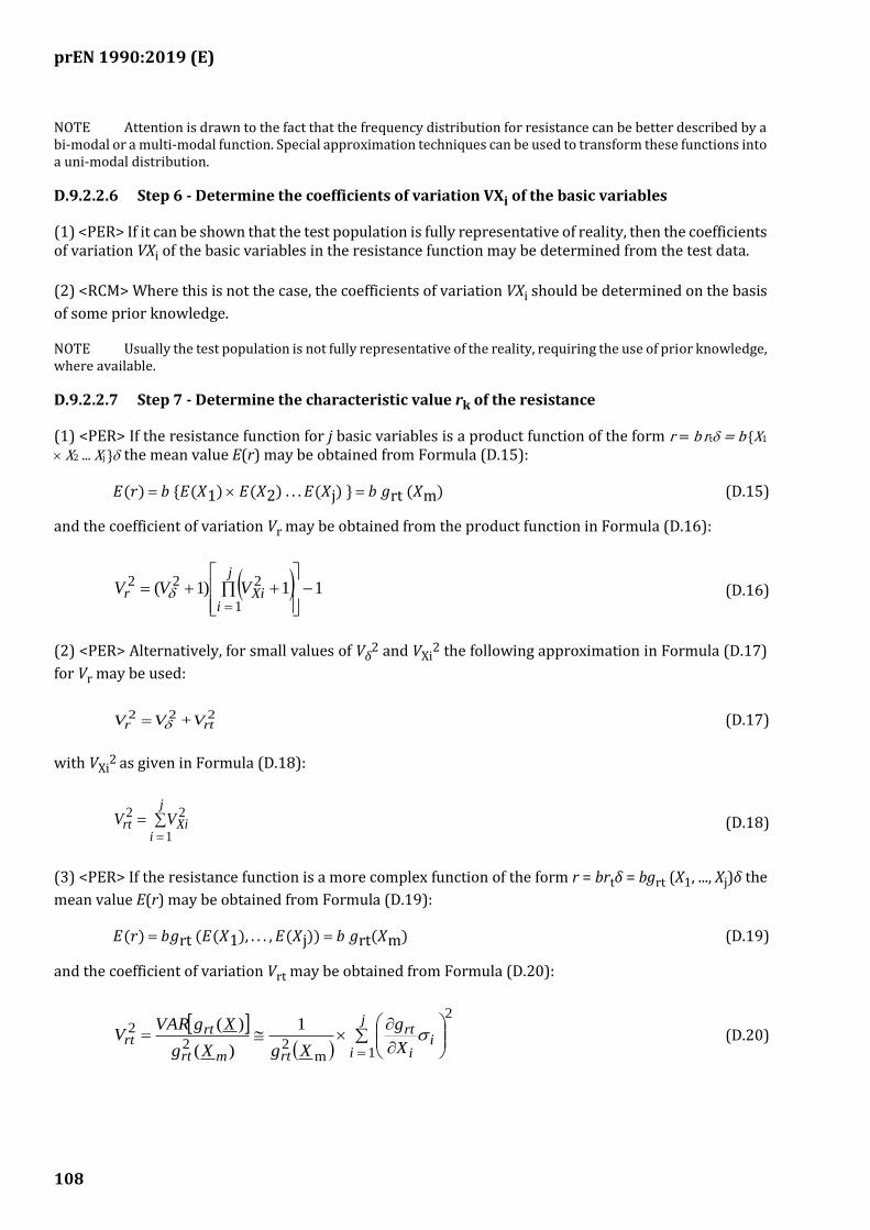
prEN 1990:2019 (E)
108
NOTE Attention is drawn to the fact that the frequency distribution for resistance can be better described by a bi-modal or a multi-modal function. Special approximation techniques can be used to transform these functions into a uni-modal distribution.
D.9.2.2.6 Step 6 - Determine the coefficients of variation VXi of the basic variables
(1) <PER> If it can be shown that the test population is fully representative of reality, then the coefficients of variation VXi of the basic variables in the resistance function may be determined from the test data.
(2) <RCM> Where this is not the case, the coefficients of variation VXi should be determined on the basis
of some prior knowledge.
NOTE Usually the test population is not fully representative of the reality, requiring the use of prior knowledge, where available.
D.9.2.2.7 Step 7 - Determine the characteristic value rk of the resistance
(1) <PER> If the resistance function for j basic variables is a product function of the form r = b rt = b {X1
X2 ... Xj } the mean value E(r) may be obtained from Formula (D.15):
𝐸(𝑟) = 𝑏 {𝐸(𝑋1) 𝐸(𝑋2) . . . 𝐸(𝑋j) } = 𝑏 𝑔rt (𝑋m) (D.15)
and the coefficient of variation Vr may be obtained from the product function in Formula (D.16):
( ) 11)1(1
222 −
++==
j
iXir VVV
(D.16)
(2) <PER> Alternatively, for small values of Vδ2 and VXi
2 the following approximation in Formula (D.17)
for Vr may be used:
222rtr V + VV = (D.17)
with VXi2 as given in Formula (D.18):
==
j
iXirt VV
1
22
(D.18)
(3) <PER> If the resistance function is a more complex function of the form r = brtδ = bgrt (X1, ..., Xj)δ the
mean value E(r) may be obtained from Formula (D.19):
𝐸(𝑟) = 𝑏𝑔rt (𝐸(𝑋1), . . . , 𝐸(𝑋j)) = 𝑏 𝑔rt(𝑋m) (D.19)
and the coefficient of variation Vrt may be obtained from Formula (D.20):
( )
=
=
j
ii
i
rt
rtmrt
rtrt
X
g
XgXg
XgVARV
1
2
m22
2 1
)(
)(
(D.20)
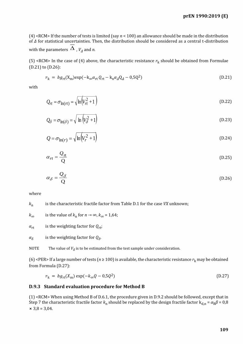
prEN 1990:2019 (E)
109
(4) <RCM> If the number of tests is limited (say n < 100) an allowance should be made in the distribution of Δ for statistical uncertainties. Then, the distribution should be considered as a central t-distribution
with the parameters , VΔ and n.
(5) <RCM> In the case of (4) above, the characteristic resistance rk should be obtained from Formulae
(D.21) to (D.26):
𝑟k = 𝑏𝑔rt(Xm)exp(−k∞𝛼rt 𝑄rt− kn𝛼𝛥Q𝛥− 0,5Q
2) (D.21)
with
( ) 1+ln 2)ln( rtrtrt VQ ==
(D.22)
( )1+ ln 2)ln( V Q ==
(D.23)
( )1+ln 2)ln( rr VQ ==
(D.24)
Q
rtQrt =
(D.25)
Q
Q =
(D.26)
where
kn is the characteristic fractile factor from Table D.1 for the case VX unknown;
k∞ is the value of kn for n → ∞, k∞ = 1,64;
αrt is the weighting factor for Qrt;
αδ is the weighting factor for Qδ.
NOTE The value of Vδ is to be estimated from the test sample under consideration.
(6) <PER> If a large number of tests (n ≥ 100) is available, the characteristic resistance rk may be obtained
from Formula (D.27):
𝑟k = 𝑏𝑔rt(𝑋m) exp(−𝑘∞𝑄 − 0,5𝑄2) (D.27)
D.9.3 Standard evaluation procedure for Method B
(1) <RCM> When using Method B of D.6.1, the procedure given in D.9.2 should be followed, except that in Step 7 the characteristic fractile factor kn should be replaced by the design fractile factor kd,n = αRβ = 0,8
⨯ 3,8 = 3,04.
prEN 1990:2019 (E)
110
NOTE The above values are those commonly used to obtain the design value rd of the resistance, see Annex C.
(2) <RCM> For the case of a limited number of tests the design value rd should be obtained from Formula
(D.28):
𝑟d = 𝑏𝑔rt(𝑋m) exp(−𝑘d, ∞𝛼rt𝑄rt − 𝑘d, n
𝛼𝛿𝑄𝛿− 0,5 𝑄2) (D.28)
where
kd,n is the design fractile factor from Table D.2 for the case “VX unknown”;
kd,∞ is the value of kd,n for n → ∞, k d,∞ = 3,04.
NOTE The value of Vδ is to be estimated from the test sample under consideration.
(3) <PER> For the case of a large number of tests the design value rd may be obtained from Formula
(D.29):
𝑟d = 𝑏𝑔rt(𝑋m) exp(−𝑘d, ∞𝑄 − 0,5𝑄2) (D.29)
D.9.4 Use of additional prior knowledge
(1) <PER> If the validity of the resistance function rt and an upper bound (conservative estimate) for the
coefficient of variation Vr are already known from a significant number of previous tests, the following
simplified procedure may be adopted when further tests are carried out.
(2) <PER> If only one further test is carried out, the characteristic value rk may be determined from the
result re of this test by applying Formula (D.30):
rk = ηkre (D.30)
where
ηk is a reduction factor applicable in the case of prior knowledge that may be obtained from
Formula (D.31):
𝜂k = 0,9 exp(−2,31𝑉r− 0,5𝑉r2) (D.31)
where
Vr is the maximum coefficient of variation observed in previous tests.
(3) <PER> If two or three further tests are carried out, the characteristic value rk may be determined from
the mean value rem of the test results by applying Formula (D.32):
𝑟k = 𝜂k𝑟em (D.32)
where
ηk is a reduction factor applicable in the case of prior knowledge that may be obtained from
Formula (D.33):
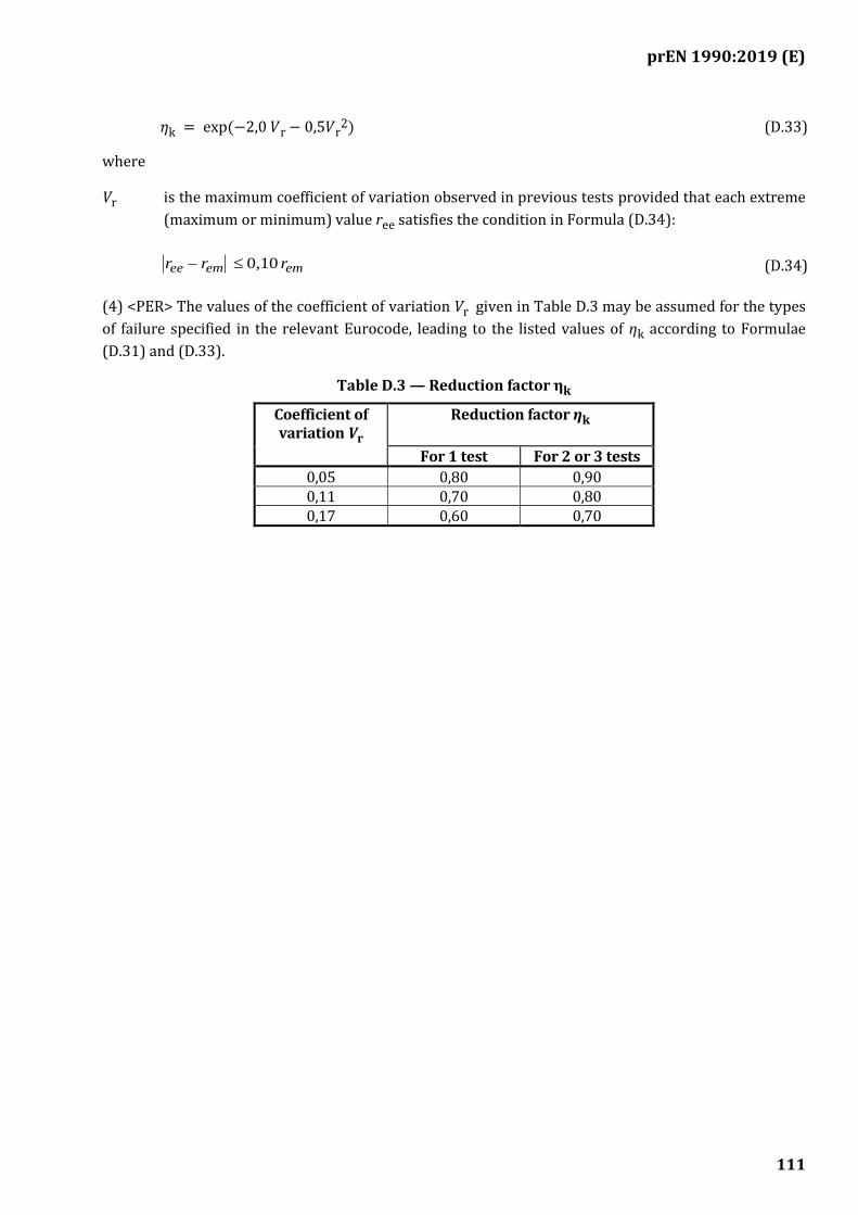
prEN 1990:2019 (E)
111
𝜂k = exp(−2,0 𝑉r− 0,5𝑉r2) (D.33)
where
Vr is the maximum coefficient of variation observed in previous tests provided that each extreme
(maximum or minimum) value ree satisfies the condition in Formula (D.34):
ememee rrr 0,10 − (D.34)
(4) <PER> The values of the coefficient of variation Vr given in Table D.3 may be assumed for the types
of failure specified in the relevant Eurocode, leading to the listed values of ηk according to Formulae
(D.31) and (D.33).
Table D.3 — Reduction factor ηk
Coefficient of variation Vr
Reduction factor ηk
For 1 test For 2 or 3 tests
0,05 0,80 0,90 0,11 0,70 0,80 0,17 0,60 0,70

prEN 1990:2019 (E)
112
(informative)
Additional guidance for enhancing the robustness of buildings and bridges
E.1 Use of this informative Annex
(1) This informative Annex provides additional guidance to that given in 4.4, for enhancing the robustness of buildings and bridges.
NOTE 1 National choice on the application of this informative annex is given in the National Annex. If the National Annex contains no information on the application of this informative annex, it can be used.
NOTE 2 Although the guidance contained in this Annex is for buildings and bridges, its principles can be applied to other types of structure.
E.2 Scope and field of application
(1) The aim of enhancing the robustness in accordance with this Annex is either to prevent disproportionate consequences as a result of hazardous event such as the failure or collapse of a structural member or part of a structure, or to provide some additional structural resistance to reduce the likelihood and extent of such an event.
(2) Design for identified accidental actions should be undertaken in accordance with EN 1991 and other relevant Eurocodes.
NOTE 1 An identified accidental action is one against which a structure is explicitly designed on having been identified as possible to occur during its design service life. Such an action is considered known, either in terms of its relevant statistics or a specified design value.
NOTE 2 The distinction between designing for robustness in accordance with this Annex and designing for identified accidental actions in accordance with EN 1991, which also contributes to the structural performance in terms of robustness (see Note 3), is shown in Figure E.1.
NOTE 3 In the case of design for identified accidental actions in accordance with EN 1991 a target level of reliability is expected to be achieved. Whilst the strategies and methods given in this Annex enhance structural performance regarding robustness, they are not generally associated with a target level of reliability as in structural member design against identified actions and could involve consideration of a conditional reliability.
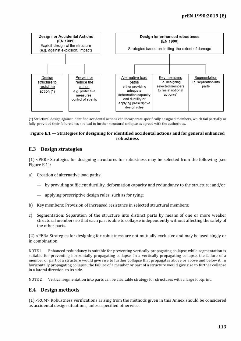
prEN 1990:2019 (E)
113
(*) Structural design against identified accidental actions can incorporate specifically designed members, which fail partially or
fully, provided their failure does not lead to further structural collapse as agreed with the authorities.
Figure E.1 — Strategies for designing for identified accidental actions and for general enhanced robustness
E.3 Design strategies
(1) <PER> Strategies for designing structures for robustness may be selected from the following (see Figure E.1):
a) Creation of alternative load paths:
— by providing sufficient ductility, deformation capacity and redundancy to the structure; and/or
— applying prescriptive design rules, such as for tying;
b) Key members: Provision of increased resistance in selected structural members;
c) Segmentation: Separation of the structure into distinct parts by means of one or more weaker structural members so that each part is able to collapse independently without affecting the safety of the other parts.
(2) <PER> Strategies for designing for robustness are not mutually exclusive and may be used singly or in combination.
NOTE 1 Enhanced redundancy is suitable for preventing vertically propagating collapse while segmentation is suitable for preventing horizontally propagating collapse. In a vertically propagating collapse, the failure of a member or part of a structure would give rise to further collapse that propagates above or above and below it. In horizontally propagating collapse, the failure of a member or part of a structure would give rise to further collapse in a lateral direction, to its side.
NOTE 2 Vertical segmentation into parts can be a suitable strategy for structures with a large footprint.
E.4 Design methods
(1) <RCM> Robustness verifications arising from the methods given in this Annex should be considered as accidental design situations, unless specified otherwise.
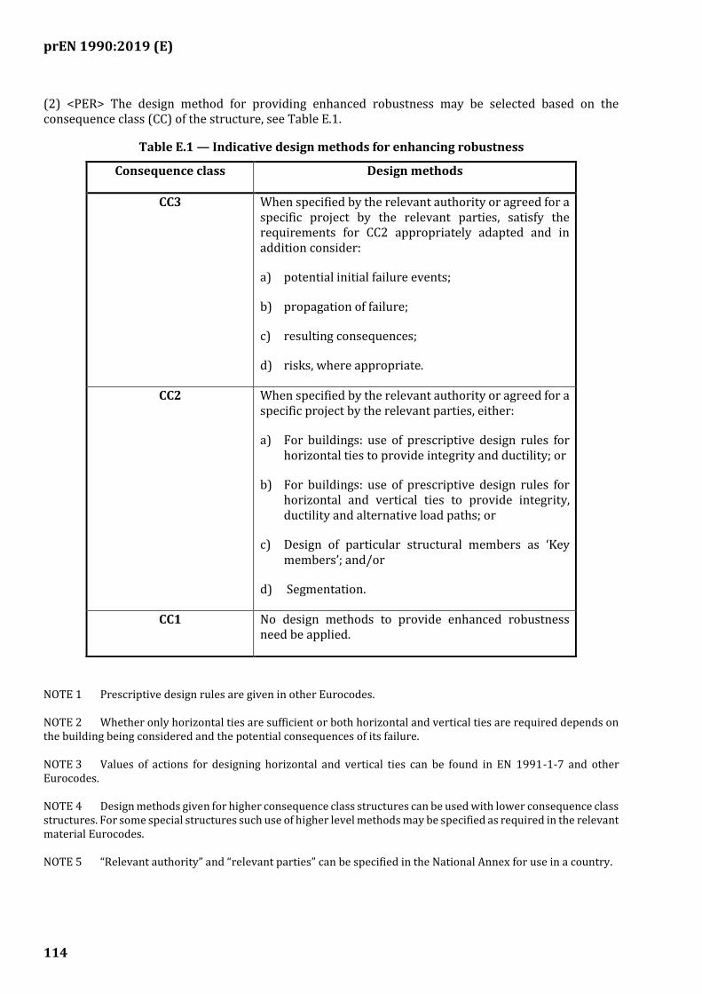
prEN 1990:2019 (E)
114
(2) <PER> The design method for providing enhanced robustness may be selected based on the consequence class (CC) of the structure, see Table E.1.
Table E.1 — Indicative design methods for enhancing robustness
Consequence class Design methods
CC3 When specified by the relevant authority or agreed for a specific project by the relevant parties, satisfy the requirements for CC2 appropriately adapted and in addition consider:
a) potential initial failure events;
b) propagation of failure;
c) resulting consequences;
d) risks, where appropriate.
CC2 When specified by the relevant authority or agreed for a specific project by the relevant parties, either:
a) For buildings: use of prescriptive design rules for horizontal ties to provide integrity and ductility; or
b) For buildings: use of prescriptive design rules for horizontal and vertical ties to provide integrity, ductility and alternative load paths; or
c) Design of particular structural members as ‘Key members’; and/or
d) Segmentation.
CC1 No design methods to provide enhanced robustness need be applied.
NOTE 1 Prescriptive design rules are given in other Eurocodes.
NOTE 2 Whether only horizontal ties are sufficient or both horizontal and vertical ties are required depends on the building being considered and the potential consequences of its failure.
NOTE 3 Values of actions for designing horizontal and vertical ties can be found in EN 1991-1-7 and other Eurocodes.
NOTE 4 Design methods given for higher consequence class structures can be used with lower consequence class structures. For some special structures such use of higher level methods may be specified as required in the relevant material Eurocodes.
NOTE 5 “Relevant authority” and “relevant parties” can be specified in the National Annex for use in a country.
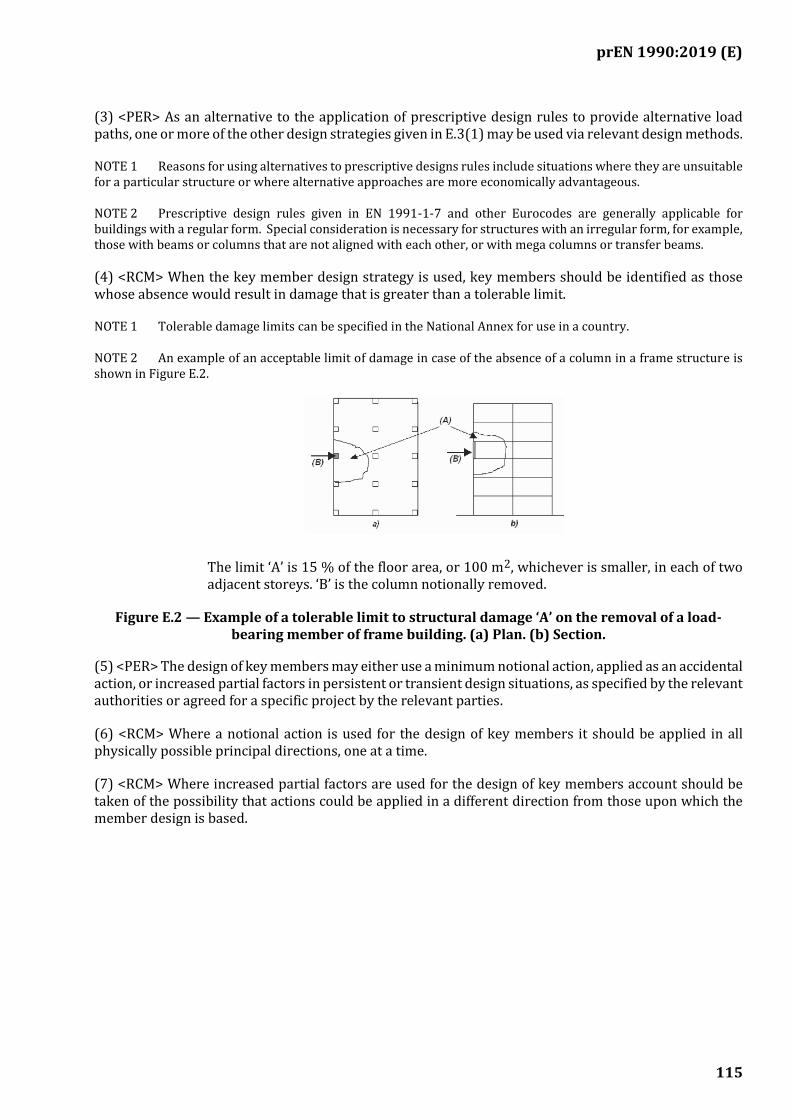
prEN 1990:2019 (E)
115
(3) <PER> As an alternative to the application of prescriptive design rules to provide alternative load paths, one or more of the other design strategies given in E.3(1) may be used via relevant design methods.
NOTE 1 Reasons for using alternatives to prescriptive designs rules include situations where they are unsuitable for a particular structure or where alternative approaches are more economically advantageous.
NOTE 2 Prescriptive design rules given in EN 1991-1-7 and other Eurocodes are generally applicable for buildings with a regular form. Special consideration is necessary for structures with an irregular form, for example, those with beams or columns that are not aligned with each other, or with mega columns or transfer beams.
(4) <RCM> When the key member design strategy is used, key members should be identified as those whose absence would result in damage that is greater than a tolerable limit.
NOTE 1 Tolerable damage limits can be specified in the National Annex for use in a country.
NOTE 2 An example of an acceptable limit of damage in case of the absence of a column in a frame structure is shown in Figure E.2.
The limit ‘A’ is 15 % of the floor area, or 100 m2, whichever is smaller, in each of two adjacent storeys. ‘B’ is the column notionally removed.
Figure E.2 — Example of a tolerable limit to structural damage ‘A’ on the removal of a load-bearing member of frame building. (a) Plan. (b) Section.
(5) <PER> The design of key members may either use a minimum notional action, applied as an accidental action, or increased partial factors in persistent or transient design situations, as specified by the relevant authorities or agreed for a specific project by the relevant parties.
(6) <RCM> Where a notional action is used for the design of key members it should be applied in all physically possible principal directions, one at a time.
(7) <RCM> Where increased partial factors are used for the design of key members account should be taken of the possibility that actions could be applied in a different direction from those upon which the member design is based.
prEN 1990:2019 (E)
116
(informative)
Rain-flow and reservoir counting methods for the determination of stress
ranges due to high-cycle fatigue
F.1 Use of this informative Annex
(1) This informative Annex provides guidance on rain-flow and reservoir counting methods for the determination of stress ranges due to high-cycle fatigue.
NOTE National choice on the application of this Informative Annex is given in the National Annex. If the National Annex contains no information on the application of this informative annex, it can be used.
F.2 Scope and field of application
(1) This informative annex applies to structures subjected to high-cycle fatigue.
F.3 Rain-flow counting method
(1) The rain-flow counting method consists in the steps given in the example in Figure F.1.
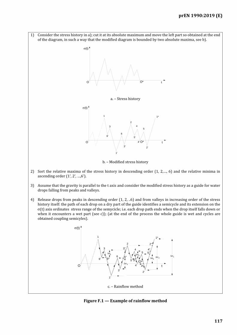
prEN 1990:2019 (E)
117
1) Consider the stress history in a); cut it at its absolute maximum and move the left part so obtained at the end of the diagram, in such a way that the modified diagram is bounded by two absolute maxima, see b).
a. – Stress history
b. – Modified stress history
2) Sort the relative maxima of the stress history in descending order (1, 2,…, 6) and the relative minima in ascending order (1’, 2’, …,6’).
3) Assume that the gravity is parallel to the t axis and consider the modified stress history as a guide for water drops falling from peaks and valleys.
4) Release drops from peaks in descending order (1, 2, ..6) and from valleys in increasing order of the stress history itself: the path of each drop on a dry part of the guide identifies a semicycle and its extension on the (t) axis ordinates stress range of the semycicle; i.e. each drop path ends when the drop itself falls down or when it encounters a wet part (see c)); (at the end of the process the whole guide is wet and cycles are obtained coupling semicyles).
c. – Rainflow method
Figure F.1 — Example of rainflow method
(t)
tO*O
3 4
2'
6'
(t)
1'
5
3'
t
6
1*
4'O
1
2
O*
5'
5'
6"
O
1
2
O*6' 4
5
5"
1
3 4
2'
6
(t)
2"
1'
4*
5
6*
3'
3"
t
4"
6
3
1*
5*
4'
2

prEN 1990:2019 (E)
118
F.4 Reservoir counting method
(1) The reservoir counting method consists in the steps given in the example in Figure F.2.
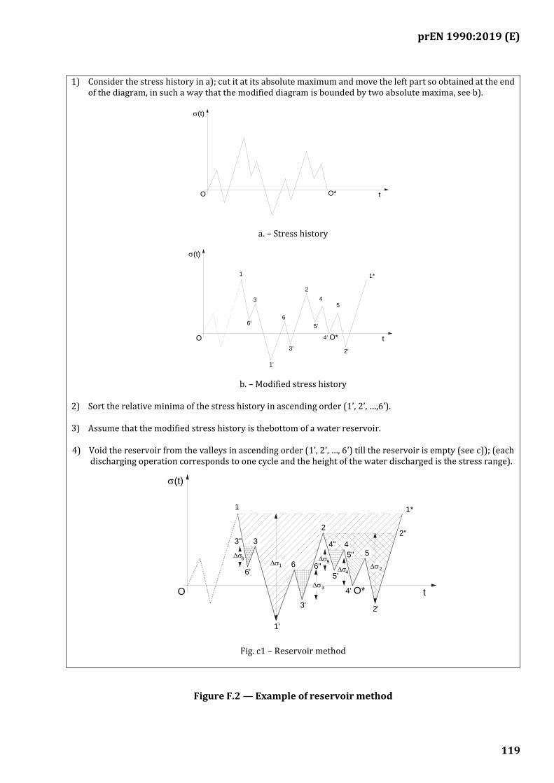
prEN 1990:2019 (E)
119
1) Consider the stress history in a); cut it at its absolute maximum and move the left part so obtained at the end of the diagram, in such a way that the modified diagram is bounded by two absolute maxima, see b).
a. – Stress history
b. – Modified stress history
2) Sort the relative minima of the stress history in ascending order (1’, 2’, …,6’).
3) Assume that the modified stress history is thebottom of a water reservoir.
4) Void the reservoir from the valleys in ascending order (1’, 2’, …, 6’) till the reservoir is empty (see c)); (each discharging operation corresponds to one cycle and the height of the water discharged is the stress range).
Fig. c1 – Reservoir method
Figure F.2 — Example of reservoir method
(t)
tO*O
3 4
2'
6'
(t)
1'
5
3'
t
6
1*
4'O
1
2
O*
5'
6
3
O
4
2'
6'2
3"
1'
2"
5
1
3'
3
46"
(t)
6
4"
1*
4'
1
5"
t
2
O*
5'
5

prEN 1990:2019 (E)
120
(Normative)
Basis of design for bearings
[Drafting note: Annex G will be included in a subsequent amendment]

prEN 1990:2019 (E)
121
(Informative)
Verifications concerning vibration of footbridges due to pedestrian traffic
[Drafting note: Annex H will be included in a subsequent amendment]

prEN 1990:2019 (E)
122
Bibliography
ISO 2394, General principles on reliability for structures
ISO 2631:1997, Mechanical vibration and shock – Evaluation of human exposure to whole-body vibration
ISO 3898, Basis for design of structures – Notations – General symbols
ISO 6707-1, Building and civil engineering – Vocabulary – Part 1: General terms
ISO 8930, General principles on reliability for structures - List of equivalent terms
EN ISO 9001:2000, Quality management systems – Requirements (ISO 9001:2000)
ISO 10137, Basis for design of structures – Serviceability of buildings against vibrations
ISO 8402, Quality management and quality assurance – Vocabulary