eurocode 1: actions on structures – part 1-2: general...
TRANSCRIPT

Brussels, 18-20 February 2008 – Dissemination of information workshop 1
Background and ApplicationsEUROCODES
Eurocode 1: Actions on structures – Part 1-2: General actions – Actions on structures
exposed to fire
Tom LennonPrincipal Consultant, BRE, UK

Brussels, 18-20 February 2008 – Dissemination of information workshop 2
EUROCODESBackground and Applications Scope of presentation
Introduction to structural fire engineering design
Section 3 Thermal actions for temperature analysis3.2 Nominal temperature-time curves3.3 Natural fire models
Section 4 Mechanical actions for structural analysis4.2 Simultaneity of actions4.3 Combination rules for actions
Annex A Parametric time-temperature curvesAnnex B Thermal actions for external membersAnnex C Localised firesAnnex D Advanced fire modelsAnnex E Fire load densitiesAnnex F Equivalent time of fire exposureAnnex G Configuration factor
Worked example – Equivalent time of fire exposure

Brussels, 18-20 February 2008 – Dissemination of information workshop 3
EUROCODESBackground and Applications Introduction to structural fire engineering design
Why structural fire engineering?
What is structural fire engineering design?
How do we do it?

Brussels, 18-20 February 2008 – Dissemination of information workshop 4
EUROCODESBackground and Applications Structural fire engineering design – Do we need it?
Existing body of data
Tried and tested solutions
Accepted levels of safety and reliability
Tabulated data generally conservative

Brussels, 18-20 February 2008 – Dissemination of information workshop 5
EUROCODESBackground and Applications
Structural fire engineering design – Do we need it? –YES!
Levels of safety unknownDegree of conservatism unknownNo account of interaction between structural
elementsNo account of alternative load carrying
mechanismsNo account of alternative modes of failure

Brussels, 18-20 February 2008 – Dissemination of information workshop 6
EUROCODESBackground and Applications Structural fire engineering design – Do we need it? – YES!
Complex structures not covered by existing regulatory requirement – “fire engineering may be the only suitable approach”
Provides for a more rational approach to the design of buildings for fire if undertaken as part of an overall fire safety strategy
Change of use or renovation of existing structure – possible increased fire resistance requirement, removal of existing means of ensuring fire resistance
Uncertainties in existing prescriptive approach

Brussels, 18-20 February 2008 – Dissemination of information workshop 7
EUROCODESBackground and Applications
Structural fire engineering design – what is it?
Time
FLASHOVER Natural fire curve
Tem
pera
ture
Ignition - Smouldering Heating Cooling
Standard fire curve
Life safety Structural damage – risk of collapse – structural fire engineering only concerned with this phase of the fire

Brussels, 18-20 February 2008 – Dissemination of information workshop 8
EUROCODESBackground and Applications
Performance-Based Code (Physically based Thermal Actions)
Selection of Simple or Advanced Fire Development Models
Prescriptive Rules (Thermal Actions by Nominal Fire
Calculation of Mechanical Actions at Boundaries
Member Analysis
Project Design
Analysis of Part of the Structure
Analysis of Entire
Structure
Calculation of Mechanical Actions at Boundaries
Selection of Mechanical
Actions
Advanced Calculation
Models
Simple Calculation
Models If available
Calculation of Mechanical Actions at Boundaries
Member Analysis
Analysis of Part of the Structure
Analysis of Entire
Structure
Calculation of Mechanical Actions at Boundaries
Selection of Mechanical
Actions
Advanced Calculation
Models
Simple Calculation
Models If available
Tabulated Data
General - Design Procedures

Brussels, 18-20 February 2008 – Dissemination of information workshop 9
EUROCODESBackground and Applications Structural fire design procedure
Structural fire design procedure takes into account:
Selection of relevant design fire scenariosDetermination of corresponding design firesCalculation of temperature within the
structural membersCalculation of mechanical behaviour of the
structure exposed to fireEN1991-1-2 is principally concerned with the
first two above. Fire parts of the material codes cover the remaining two.

Brussels, 18-20 February 2008 – Dissemination of information workshop 10
EUROCODESBackground and Applications Consider relevant design fire scenario
Building fire / tunnel fire / petrochemical fireLocalised fire / fully developed fireIdentification of suitable compartment
size/occupancy/ventilation condition for subsequent analysis – representative of “reasonable worst case scenario”
The choice of the design fire scenario will dictate the choice of the design fire to be used in subsequent analysis.
The choice of a particular fire design scenario should be based on a risk assessment taking into account the likely ignition sources and any fire detection/suppression systems available.

Brussels, 18-20 February 2008 – Dissemination of information workshop 11
EUROCODESBackground and Applications Choose appropriate design fire
For fully developed post-flashover building (compartment) fires the usual choice is between nominal and natural fire exposures
Nominal fires are representative fires for the purposes of classification and comparison but bear no relationship to the specific characteristics (fire load, thermal properties of compartment linings, ventilation condition) of the building considered
Natural fires are calculation techniques based on a consideration of the physical parameters specific to a particular building.

Brussels, 18-20 February 2008 – Dissemination of information workshop 12
EUROCODESBackground and Applications Modelling compartment fires
In compartment fires it is often assumed that the whole compartment is fully involved in the fire at the same time and the same temperature applies throughout. Such a scenario is the basis of a one zone model.
Two zone models exist in which the height of the compartment is separated into two gaseous layers each with their own thermal environment
Three zone models exist in which there is a mixed gas layer separating the upper and lower gas levels
Computational Fluid Dynamics (CFD) may be used to analyse fires in which there are no definite boundaries to the gaseous state. This type of analysis would be suitable for very large compartments such as airport terminals, atria and sports stadia. It is often used to model smoke movement.

Brussels, 18-20 February 2008 – Dissemination of information workshop 13
EUROCODESBackground and Applications Post-Flashover Fire Models
In a compartment flashover occurs when sustained flaming from combustibles reach the ceiling and the temperature of the hot gas layer is between 550°C and 600°C.
After flashover the rate of heat release will increase rapidly until it reaches a maximum value for the enclosure. To simplify design, the growth period between the onset of flashover and the maximum heat release rate is usually ignored and it may be assumed that when flashover occurs the rate of heat release instantaneously increases to the maximum value set by the available air.

Brussels, 18-20 February 2008 – Dissemination of information workshop 14
EUROCODESBackground and Applications Section 3 Thermal actions for temperature analysis
Thermal actions are given by the net heat flux:
rnetcnetnet hhh ,, +=
Convective heat flux
Radiative heat flux

Brussels, 18-20 February 2008 – Dissemination of information workshop 15
EUROCODESBackground and Applications 2.2 Nominal temperature-time curves
Standard temperature-time curve
0
200
400
600
800
1000
1200
0 10 20 30 40 50 60 70 80 90 100 110 120
945ºC
θg = 20+log10345(8t+1)

Brussels, 18-20 February 2008 – Dissemination of information workshop 16
EUROCODESBackground and Applications Nominal fire curves
Other nominal curves include:Smouldering fire curve
“Semi-Natural” fire curve
External fire exposure curve*
Hydrocarbon curve*
Modified hydrocarbon curve
Tunnel lining curves – RWS/RABT
* Included in the Eurocode

Brussels, 18-20 February 2008 – Dissemination of information workshop 17
EUROCODESBackground and Applications External fire temperature-time curve
0
100
200
300
400
500
600
700
800
0 10 20 30 40 50 60 70 80 90 100 110 120
Θg = 660(1 – 0.687e-0.32t – 0.313e-3.8t) + 20
Temperature constant after 22 mins at 660ºC
Brussels, 18-20 February 2008 – Dissemination of information workshop 18
EUROCODESBackground and Applications
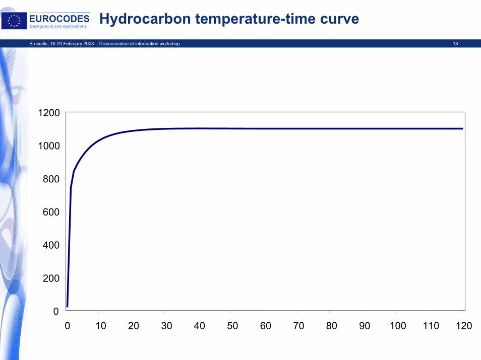
Hydrocarbon temperature-time curve
0
200
400
600
800
1000
1200
0 10 20 30 40 50 60 70 80 90 100 110 120

Brussels, 18-20 February 2008 – Dissemination of information workshop 19
EUROCODESBackground and Applications 2.3 Natural fire models
Natural fire models are based on specific physical parameters with a limited field of application
For compartment fires a uniform temperature distribution as a function of time is generally assumed
For localised fires a non-uniform temperature distribution as a function of time is assumed

Brussels, 18-20 February 2008 – Dissemination of information workshop 20
EUROCODESBackground and Applications Natural fire models
Simplified fire models – compartment fires
Any appropriate fire model may be used considering at least the fire load density and the ventilation conditions
The parametric approach in Annex A of the code is one example of a simplified natural fire model

Brussels, 18-20 February 2008 – Dissemination of information workshop 21
EUROCODESBackground and Applications Natural fire models
Simplified fire models – external members
For external members the radiative heat flux should be calculated from the sum of the radiation from the compartment and from the flames emerging from the opening
An example of a simplified calculation method for external members is given in Annex B of the Code

Brussels, 18-20 February 2008 – Dissemination of information workshop 22
EUROCODESBackground and Applications Natural fire models
Simplified fire models – localised fires
In many cases flashover is unlikely to occur. In such cases a localised fire should be considered.
Annex C presents an example of a procedure for calculating temperatures in the event of a localised fire

Brussels, 18-20 February 2008 – Dissemination of information workshop 23
EUROCODESBackground and Applications Section 4 Mechanical actions for structural analysis
If they are likely to occur during a fire the same actions assumed for normal design should be considered.
Indirect actions can occur due to constrained expansion and deformation caused by temperature changes within the structure caused by the fire.

Brussels, 18-20 February 2008 – Dissemination of information workshop 24
EUROCODESBackground and Applications Section 4 Mechanical actions for structural analysis
INDIRECT thermal actions should be considered. EXCEPT where the resulting actions are:
recognized a priori to be negligible or favourable.
accounted for by conservatively chosen models and boundary conditions or implicitly considered by conservatively specified fire safety requirements.

Brussels, 18-20 February 2008 – Dissemination of information workshop 25
EUROCODESBackground and Applications Section 4 Mechanical actions for structural analysis
The indirect actions should be determined using the thermal and mechanical properties given in the fire parts of EN1992 to EN1996 and EN1999.
For member design subjected to the standard fire only indirect actions arising from the thermal distribution through the cross-section needs to be considered.

Brussels, 18-20 February 2008 – Dissemination of information workshop 26
EUROCODESBackground and Applications Section 4 Mechanical actions for structural analysis
Actions considered for ‘normal’ design should also be considered for fire design if they are likely to act at the time of a possible fire.
Variable actions should be defined for the accidental design situation, with associated partial load factors, as given in EN1990.

Brussels, 18-20 February 2008 – Dissemination of information workshop 27
EUROCODESBackground and Applications Section 4 Mechanical actions for structural analysis
Simultaneous action with other independent accidental actions does not need to be considered
Additional actions (i.e partial collapse) may need to be considered during the fire exposure
Fire walls may be required to resist horizontal impact loading according to EN1363-2

Brussels, 18-20 February 2008 – Dissemination of information workshop 28
EUROCODESBackground and Applications Section 4 Mechanical actions for structural analysis
When indirect actions do not need to be considered, and there is no prestressing force, the total design action (load) considering permanent and the leading variable action is given by;
( )∑≥
+1
11211j
,k,,j,k Qor""G ψψ
The use of ψ1,1 or ψ2,1 is defined in the National Annex

Brussels, 18-20 February 2008 – Dissemination of information workshop 29
EUROCODESBackground and Applications
The values of ψ1,1 and ψ2,1 are given in Annex A of EN1990:2002

Brussels, 18-20 February 2008 – Dissemination of information workshop 30
EUROCODESBackground and Applications Mechanical actions for structural analysis
As a simplification, the effect of actions in the fire conditioncan be determined from those used in normal temperature design
dfid,fit,d,fi EEE η==
d
t,d,fifi R
E=ηWhere

Brussels, 18-20 February 2008 – Dissemination of information workshop 31
EUROCODESBackground and Applications Annex A Parametric Temperature-Time Curves
EN 1991-1-2 Annex A- Parametric Equation
θg = 1325(1-0.324e-0.2t*-0.204e-1.7t*-0.472e-19t*)where t* = t.Γ
and Γ = (O/b)²/(0.04/1160)²O is the opening factor
and b relates to the thermal inertia √(ρcλ)Where ρ = density (kg/m³)c = specific heat (J/kgK)
Λ = thermal conductivity (W/mK)

Brussels, 18-20 February 2008 – Dissemination of information workshop 32
EUROCODESBackground and Applications Parametric equation (contd)
O = opening factor Av√h/At (m½)
Av = area of vertical openings (m²)
h = height of vertical openings (m)
At = total area of enclosure – walls, ceiling and floor including openings (m²)

Brussels, 18-20 February 2008 – Dissemination of information workshop 33
EUROCODESBackground and Applications Parametric Equation
Scope of Equation
- 0.02 ≤ O ≤ 0.2 (m½) (lower limit of 0.01 in UK NA)- 100 ≤ b ≤ 2000 (J/m² s½ °K)- Af ≤ 500m² (No restriction in UK NA)
- mainly cellulosic fire loads- maximum compartment height = 4m (No restriction in UK NA)- concept of limiting duration (20 minutes for offices)

Brussels, 18-20 February 2008 – Dissemination of information workshop 34
EUROCODESBackground and Applications EC1 Parametric exposure
Cooling phaseΘg = θmax – 625(t*-t*max.x) for t*max ≤ 0.5Θg = θmax – 250(3-t*max)(t*-t*max.x) for t*max < 2Θg = θmax – 250(t*-t*max.x) for t*max ≥ 2
Where t*max = (0.2x10⁻³. qt,d/O).ΓAnd tmax = maximum of (0.2x10⁻³. qt,d/O) and tlimWith tlim = 25 minutes for slow fire growth rate,
20 minutes for medium fire growth rate and 15 minutes for fast fire growth rate

Brussels, 18-20 February 2008 – Dissemination of information workshop 35
EUROCODESBackground and Applications
comparison between EC1 parametric calculation and measured values
0
200
400
600
800
1000
1200
0 10 20 30 40 50 60 70
time (mins)
tem
pera
ture
(deg
C)
test 1 prediction test 2

Brussels, 18-20 February 2008 – Dissemination of information workshop 36
EUROCODESBackground and Applications
Time temperature curves
0
200
400
600
800
1000
1200
0 15 30 45 60 75 90 105 120 135 150 165 180
Time [mins]
Tem
pera
ture
[deg
C] Average temperature TEST 1
Average temperature TEST 2Parametric time temperatureISO curve

Brussels, 18-20 February 2008 – Dissemination of information workshop 37
EUROCODESBackground and Applications
Annex B Thermal actions for external members – Simplified calculation method
Allows for the determination of:
Maximum temperatures of a compartment fire
The size and temperatures of the flames emerging from the openings
Radiation and convection parameters
Takes into account effect of wind through inclusion of forced draught and no forced draught calculations

Brussels, 18-20 February 2008 – Dissemination of information workshop 38
EUROCODESBackground and Applications Annex C Localised fires
Where a fully developed fire is not possible the thermal input from a localised fire source to the structural member should be considered.
Annex C provides one possible method – The UK NA specifies an alternative methodology based on existing National information

Brussels, 18-20 February 2008 – Dissemination of information workshop 39
EUROCODESBackground and Applications Annex D Advanced Fire Models
Annex D sets out general principles associated with advanced fire models (One zone, two zone or CFD)
There is no detailed guidance and such methods should only be used by experts

Brussels, 18-20 February 2008 – Dissemination of information workshop 40
EUROCODESBackground and Applications Annex E Fire load densities
Annex E presents a method for calculating design fire load densities based on characteristic values from survey data for different occupancies
The characteristic values are modified according to the risk of fire initiation and the consequence of failure related to occupancy and compartment floor area
Active fire safety measures are taken into account through a reduction in the design fire load density
This approach is not accepted in the UK NA

Brussels, 18-20 February 2008 – Dissemination of information workshop 41
EUROCODESBackground and Applications Annex F Equivalent time of fire exposure
Provides a quick and easy method of relating a real fire exposure to an equivalent period in a standard fire resistance furnace
Mainly based on work on protected steel specimens
Recent analysis extended the use of the concept to unprotected steel for low fire resistance periods

Brussels, 18-20 February 2008 – Dissemination of information workshop 42
EUROCODESBackground and Applications
0
200
400
600
800
1000
1200
0 15 30 45 60 75 90
Time [mins]
Tem
pera
ture
[o C]
Max. Steel Temp
Te
Atmosphere(fire)
Atmosphere(furnace)
Steel(fire)
Steel(Furnace)

Brussels, 18-20 February 2008 – Dissemination of information workshop 43
EUROCODESBackground and Applications Time equivalent – calculation methods
CIB W14: te = qf c wLaw: te = kL/√(AvAt)Pettersson: te = 0.067qf(Av√h/At)-½
EC1: te,d = qf,d kb wf
Where qf,d = design fire load densitykb = factor to take into account the
thermal properties of the enclosurewf = ventilation factor to take into
account vertical and horizontal openings

Brussels, 18-20 February 2008 – Dissemination of information workshop 44
EUROCODESBackground and Applications
Time equivalent – what is it? How does it work? How do you do it?
Worked example – fire compartment within an office buildingGeometric data
Floor area (m²) 36 (6m x 6m)
Ventilation area Av (m²)
7.2 (3.6m wide by 2m high)
Height of ventilation opening h (m)
2
Height of compartment H (m)
3.6
Area of horizontal opening (roof light) Ah
0

Brussels, 18-20 February 2008 – Dissemination of information workshop 45
EUROCODESBackground and Applications
Time equivalent – thermal properties
Element Material Thermal inertia (b value –J/m²s½K)
Area (m²)
Roof Concrete 2280 36
Floor Plasterboard 520 36
Walls Plasterboard 520 76.8

Brussels, 18-20 February 2008 – Dissemination of information workshop 46
EUROCODESBackground and Applications Time equivalent worked example
te,d = (qf,d.kb.wf)kc
Where qf,d = design fire load density (MJ/m²)
kb is a factor dependent on thermal properties of the lining materialsAnd wf is a ventilation factor given by:
wf = (6/H)0.3 [0.62 + 90(0.4-αv)4] in the absence of vertical openingsWhere H is the height of the compartment (m) and αv = Av/Af
kc = factor dependent on material = 1.0 for protected steel

Brussels, 18-20 February 2008 – Dissemination of information workshop 47
EUROCODESBackground and Applications
Time equivalent worked example
b = (ρcλ)½
(J/m²s½K)kb (min.m²/MJ)
b > 2500 0.04 (0.055)
720≤b≤2500 0.055 (0.07)
b<720 0.07 (0.09)

Brussels, 18-20 February 2008 – Dissemination of information workshop 48
EUROCODESBackground and Applications
Time equivalent worked example
Occupancy Characteristic fire load density (MJ/m²) 80% fractile
Dwelling 948 (400)
Hospital 280 (350)
Hotel 377 (400)
Office 511 (570)
School classroom 347 (360)

Brussels, 18-20 February 2008 – Dissemination of information workshop 49
EUROCODESBackground and Applications
Time equivalent worked example
qf,d = 570 MJ/m²
wf = 0.863 (αv = 0.2)
kb = 0.07 (b = 945 (Σ(bjAj/Aj))
kc = 1.0 (protected steel beam)
te,d = 570 x 0.863 x 0.07 = 34 minutes therefore 60 minutes fire protection would be appropriate

Brussels, 18-20 February 2008 – Dissemination of information workshop 50
EUROCODESBackground and Applications Time equivalent – important questions to ask
Have sensitivity studies been carried out on % glazing removed during the fire. Breaking of glass during a fire is very difficult to predict. In reality the ventilation area will vary with time during the fire process.
What value has been used for the fire load density
What confidence is there in the final configuration of the compartment linings? In the absence of definite data then a figure of kb = 0.09 should be used (UK National Annex)

Brussels, 18-20 February 2008 – Dissemination of information workshop 51
EUROCODESBackground and Applications Annex G Configuration Factor
Text book information on general principles for radiative heat transfer
Specific guidance for external members

Brussels, 18-20 February 2008 – Dissemination of information workshop 52
EUROCODESBackground and Applications
Thank you for your attention!