eum hr9002-001_a (2009.7.2)
DESCRIPTION
nooooTRANSCRIPT

Rev. A
HR9002-001 48V/5.8kW/2.9kW Energy System
All
right
s re
serv
ed. P
assi
ng o
n an
d co
pyin
g of
this
do
cum
ent,
use
and
com
mun
icat
ion
of it
s co
nten
ts
not p
erm
itted
with
out w
ritte
n au
thor
izat
ion
from
AcB
el.
HR9002-001
Energy System
User Manual

All
right
s re
serv
ed. P
assi
ng o
n an
d co
pyin
g of
this
do
cum
ent,
use
and
com
mun
icat
ion
of it
s co
nten
ts
not p
erm
itted
with
out w
ritte
n au
thor
izat
ion
from
AcB
el.
Rev. A
HR9002-001 48V/5.8kW/2.9kW Energy System
Contents
Chapter 1 Introduction
1.1 System Introduction 1-11.2 System Key Features 1-21.3 Main Applications 1-2
Chapter 2 Overview of the System
2.1 System Architecture 2-12.2 Electrical Specification 2-22.3 Environmental Specification 2-32.4 Safety Specification 2-32.5 Mechanical Specification 2-32.6 System Internal Layout 2-42.7 System Major Component List 2-52.8 System Alarm 2-52.9 System Protection 2-62.10 Battery Management 2-6
Chapter 3 Installation
3.1 Transporting 3-13.2 System Unpacking 3-13.3 General Installation Guide 3-23.4 Connection of Cables 3-3 3.4.1 Cable Entry Into System 3-3 3.4.2 Connection of AC Input and Ground Cables 3-3 3.4.3 Connection of Load Cables 3-4 3.4.4 Connection of Battery Cables 3-4 3.4.5 Connection of Signal Cables 3-5 3.4.6 Temperature Sensors Connection 3-5
3.4.7 Local and remote control and monitoring communication link 3-6
3.5 Rectifier Installation 3-73.6 Final Installation Check 3-83.7 System Power Up Procedure 3-8
Chapter 4 Maintenance & Fault Tracing
4.1 Maintenance 4-1 4.2 Recommended Spare Parts List 4-1 4.3 Fault Tracing 4-1 4.4 Replacing The Rectifier Procedure 4-3

All
right
s re
serv
ed. P
assi
ng o
n an
d co
pyin
g of
this
do
cum
ent,
use
and
com
mun
icat
ion
of it
s co
nten
ts
not p
erm
itted
with
out w
ritte
n au
thor
izat
ion
from
AcB
el.
Rev. A
HR9002-001 48V/5.8kW/2.9kW Energy System
Chapter 5 Important Notices
5.1 General Guidelines 5-1 5.1.1 Installation 5-1 5.1.2 System Operation 5-1 5.1.3 Environmental and Airflow Considerations 5-1 5.1.4 Maintenance and Repair 5-15.2 Warranty Constraints 5-2
Appendix :
1. Conductor Size Requirement for DC Applications A-12. Maintenance Record A-2

All
right
s re
serv
ed. P
assi
ng o
n an
d co
pyin
g of
this
do
cum
ent,
use
and
com
mun
icat
ion
of it
s co
nten
ts
not p
erm
itted
with
out w
ritte
n au
thor
izat
ion
from
AcB
el.
Rev. A
HR9002-001 48V/5.8kW/2.9kW Energy System 1-1
1. Introduction 1.1 System Introduction The rectifier system is specially designed for the -48V telecommunication power applications. By incorporating state-of-the-art switched mode rectifier and advanced microprocessor technology, the system is able to perform efficient AC to DC power conversion and at the same time, carry out intelligent monitoring and control functions. The system can be divided into 4 major functional blocks. They are the 1. Control and Supervisory Module 6 (CSM6)
(Refer to Fig. 1.1 for the CSM block diagram) 2. AC Power Distribution Unit (AC PDU), 3. Rectifier Modules 4. DC Power Distribution Unit (DC PDU).
The Control and Supervisory Module 6 (CSM6) consists of the CSM6-1 and CSM6-2. The CSM6 is the central supervisory unit, which monitors and controls the operating parameters of the entire system. The CSM6-1 is equipped with LCD panel and soft keypads which serve as a user-friendly interface to monitor or program various system parameters and the CSM6-2 is the Data collector which collects and processes system data before passes to CSM6-1 for display. The CSM6 supports Local and Remote Monitoring & Control functions, for local monitoring & Control, the link between the system and the PC is made through the RS-232. However for the Remote Control and Monitoring, it can be achieved through Public Switch Telephone Network (PSTN) and Ethernet(TCP/IP). The CSM6 also has the battery management function which ensures proper charging of batteries so as to maximize energy storage and to prolong the life of batteries.
Fig. 1.1 CPS Block Diagram
Control & Supervisory Module(CSM 6)
LoadAC Power
ACPDU Rectifiers DCPDU
BatteryPower pathSignal path
Control & Supervisory Module(CSM 6)
LoadAC Power
ACPDU Rectifiers DCPDU
BatteryPower pathSignal path
All
right
s re
serv
ed. P
assi
ng o
n an
d co
pyin
g of
this
do
cum
ent,
use
and
com
mun
icat
ion
of it
s co
nten
ts
not p
erm
itted
with
out w
ritte
n au
thor
izat
ion
from
AcB
el.
Rev. A
HR9002-001 48V/5.8kW/2.9kW Energy System 1-2
The AC PDU distributes AC power to the rectifiers and other portions of the system. A single pole MCB (Miniature Circuit Breaker) is available within the AC PDU to isolate the system from the mains. The AC PDU is also installed with an array of Surge Protection Device which protect the system against line surge. The rectifier modules carry out AC to DC power conversion in the system. Each rectifier is able to deliver a rated output power of 2900W at a nominal output voltage of -54V. Therefore, when the system is expanded to its fullest capacity of two rectifiers, it is capable of delivering a maximum power of 5800W to external loads and batteries. The rectifiers are modular in design, hot-swappable and exhibit excellent current share performance when operated in parallel configuration. The system is hence flexibly configurable to meet different power consumption requirements and to achieve N+1 redundancy. Control of rectifiers can be carried out in a centralized manner on the CSM6. In addition, the operating conditions of individual rectifier can also be easily monitored on the CSM6. The DC PDU distributes DC power from the rectifiers to external loads and batteries. Within the DC PDU, there are MCBs protected distribution ways to be connected to external loads. The DC PDU also incorporates two battery connections, which are equipped with two MCBs for protection purposes. The battery connections allow the system to have power backup capability in the event of an AC failure. 1.2 System Key Features Wide input voltage range High power factor and efficiency Modular rectifier design with current share and hot-swappable capability Swift and convenient rectifier installation Microprocessor based intelligent monitoring and control Equipped with user friendly LCD and keypad interface Support remote monitoring and control Intelligent battery management system Comprehensive fault protection and detection schemes Low noise and electromagnetic interference level Efficient forced air cooling ensures low component thermal stress Front access air filter leading to easy maintenance
1.3 Main Applications PBX, PABX station GSM station CDMA, TDMA, AMPS station Microwave communication station Railway switching control station Other -48V telecommunication systems

All
right
s re
serv
ed. P
assi
ng o
n an
d co
pyin
g of
this
do
cum
ent,
use
and
com
mun
icat
ion
of it
s co
nten
ts
not p
erm
itted
with
out w
ritte
n au
thor
izat
ion
from
AcB
el.
Rev. A
HR9002-001 48V/5.8kW/2.9kW Energy System 1-3
Fig. 1.2 Power system outline
465.0482.6
57.2
132.
6
441.0
400.
016
.0
100A LVDS
100A SHUNT
B1 B2
BATT. MCB
L1 L2
LOAD MCBSPDAC MCB
L3 L4 TCP/IP
CSMPower
TOP VIEW
FRONT VIEW
SIDE VIEW TOP VIEW 3D VIEW
3D VIEW
(Without Top Cover)
(Without Top Cover)
2900W SMR 2EA
CSM6
RJ45 Port
AC MCB SPD DC MCB Batt. MCB
150.
0
MBS
Alarm dry contact T.B.
AC INPUT T.B.
BACK VIEW
NG L
AC INPUT
NCCOMNO
AC Fail
LVDS AlarmLV Alarm
COMNO
Common Alarm
NCCOMNONONC COM NC
DC(+) OUTPUT
L4+B1+B2+ L3+ L2+ L1+
DC(-) OUTPUT
L4-B1-B2- L3- L2- L1-
DC(-) OUTPUT T.B.
DC(+) OUTPUT T.B.

All
right
s re
serv
ed. P
assi
ng o
n an
d co
pyin
g of
this
do
cum
ent,
use
and
com
mun
icat
ion
of it
s co
nten
ts
not p
erm
itted
with
out w
ritte
n au
thor
izat
ion
from
AcB
el.
Rev. A
HR9002-001 48V/5.8kW/2.9kW Energy System 2-1
2. Overview of the System 2.1 System Architecture The ACPDU is fed by AC cables which are terminated at the AC input terminal block. Within the ACPDU, there is a single pole 40A MCB, which serve as the mains isolator, and a two pole 20KA Surge Protection Device (SPD) module, which provide protection against incoming line surge. The DC PDU distributes DC power from the rectifiers to external distributed loads and batteries. A positive and a negative busbar carries DC power from the rectifiers to the DC PDU. DC power is then distributed to the load MCBs. The MCB provides output overload protection and serves as a switch to isolate a load from the system when necessary. There are also two battery connections within the DC PDU which is equipped with two 50A MCBs and one 100A LVDS. The MCBs and LVDS provide protection against overload and over discharge of batteries. In the event of an AC failure, energy from the batteries will flow through the DC PDU to the external distributed loads. Hence, the loads will not experience power interruption. The energy system has two rectifier compartments. Rectifier installation is swift, straightforward and does not require further connection of cables. Since the LPR rectifier is modular and hot-swappable in design, different number of rectifiers can be installed onto the system to meet varying power consumption requirements. This allows incremental system expansion to be realized easily. Maintenance work can also conveniently carried out as any rectifier can be removed and replaced without interrupting system operation.

All
right
s re
serv
ed. P
assi
ng o
n an
d co
pyin
g of
this
do
cum
ent,
use
and
com
mun
icat
ion
of it
s co
nten
ts
not p
erm
itted
with
out w
ritte
n au
thor
izat
ion
from
AcB
el.
Rev. A
HR9002-001 48V/5.8kW/2.9kW Energy System 2-2
2.2 Electrical Specification Table 2.1 Electrical Specification
System model HR9002-001
Rectifier Model OT7014
AC input
Nominal voltage 220Vac single phase
Operating voltage range (full output power) 176Vac ~ 286Vac
Operating voltage range (derated output power) 90Vac ~ 176Vac; 286Vac ~ 300Vac
Frequency 45 ~ 65Hz
Rated current (220Vac input; 54Vdc, 100% load) 29A
Maximum current (176Vac input; 54Vdc, 100% load) 37A
Efficiency (220Vac input; 54Vdc, 100% load) >91%
Power factor (220Vac input; 54Vdc, 100% load) >0.99
DC output
Nominal voltage 54Vdc
Float voltage adjustable range 40 ~ 60Vdc
Equalize voltage adjustable range 40 ~ 60Vdc
Nominal Power (100% load) 5.8kW
Soft start time > 3s
Line regulation (176 ~ 286Vac input) < ±0.1%
Load regulation (0% ~ 100% load) < ±0.5%
Current share (50% ~ 100% load) ±3% deviation from mean current
Audible noise 55dBA (1 meter)
Psophometric noise < 2mV
Load MCB 20A x 2; 40A x 2
Battery MCB 50A x 2

All
right
s re
serv
ed. P
assi
ng o
n an
d co
pyin
g of
this
do
cum
ent,
use
and
com
mun
icat
ion
of it
s co
nten
ts
not p
erm
itted
with
out w
ritte
n au
thor
izat
ion
from
AcB
el.
Rev. A
HR9002-001 48V/5.8kW/2.9kW Energy System 2-3
2.3 Environmental Specification Operating temperature : -20°C ∼ +70°C (ideal operating temperature : 25°C) Storage temperature : -40°C ∼ +80°C Relative humidity : 10%RH ∼ 90%RH (non-condensing) Altitude : < 3000 meter Illumination requirement : 750LX (even illumination)
Note : The operating environment must not contain corrosive and inflammable gas.
Good ventilation and air-conditioning is highly recommended.
2.4 Safety Specification Designed to meet UL1950, EN60950 requirements Hi-pot : Input to output 1500Vac, 50Hz for 1 minute
Input to chassis (FG) 1500Vac, 50Hz for 1 minute
Output to chassis (FG) 500Vac, 50Hz for 1 minute
Earth continuity : Safety earth to chassis (FG) 25A for 1 minute (Earth resistance < 0.1Ω)
2.5 Mechanical Specification System dimensions (Shelf): 482.6mm x 441.0mm x 132.6mm (WxDxH) Weight : 11.2kg (excluding rectifiers and batteries)
Each rectifier weights: 4.2kg

All
right
s re
serv
ed. P
assi
ng o
n an
d co
pyin
g of
this
do
cum
ent,
use
and
com
mun
icat
ion
of it
s co
nten
ts
not p
erm
itted
with
out w
ritte
n au
thor
izat
ion
from
AcB
el.
Rev. A
HR9002-001 48V/5.8kW/2.9kW Energy System 2-4
2.6 System Internal Layout
Fig. 2.1 System Internal Layout
CSM6
Fig. 2.2 Outline Drawing of CSM6-1
CSM6
Fig. 2.3 Outline Drawing of CSM6-2
B1 B2
BATT. MCB
L1 L2
LOAD MCBSPDAC MCB
L3 L4 TCP/IP
CSMPower
FRONT VIEW
TOP VIEW 3D VIEW(Without Top Cover)
MBS
BACK VIEW
NG L
AC INPUT
NCCOMNO
AC Fail
LVDS AlarmLV Alarm
COMNO
Common Alarm
NCCOMNONONC COM NC
DC(+) OUTPUT
L4+B1+B2+ L3+ L2+ L1+
DC(-) OUTPUT
L4-B1-B2- L3- L2- L1-
1 2 3
5 4 6 7
8
10
9
11

All
right
s re
serv
ed. P
assi
ng o
n an
d co
pyin
g of
this
do
cum
ent,
use
and
com
mun
icat
ion
of it
s co
nten
ts
not p
erm
itted
with
out w
ritte
n au
thor
izat
ion
from
AcB
el.
Rev. A
HR9002-001 48V/5.8kW/2.9kW Energy System 2-5
2.7 System Major Component List
2.8 System Alarm The system is equipped with various fault detection schemes and alarms to keep users informed in the event of fault conditions. When a fault occurs, the buzzer will sound and the LCD panel on the CSM6 will clearly indicate the nature of the fault. Some main fault conditions which activate alarms include AC input or DC output abnormal, rectifier fail, system temperature high, MCB tripped etc. Display of fault messages on the LCD panel is explained in the CSM6 User Manual. The system is also equipped with four voltage free relay contacts (dry contacts) to keep remote users informed when a fault occurs. The relay contacts will respond to normal and fault conditions as indicated in the table below: -
Operating Conditions COM, NO contacts COM, NC contacts
Normal condition Opened Shorted
Fault condition Shorted Opened
Item Component Specifications Q’ty
1 Rectifier Rectifier 48V/2900W 2
2 CSM6-1 CSM6-1 CARD DISPLAY UNIT FOR CSM6 1
3 CSM6-2 CSM6-2 CARD CONTROL UNIT FOR CSM6 1
4 SPD SURGE ARRESTERS 275V 20KA 2P 1
5 AC MCB AC Input MCB 40A/1P 1
MCB 20A 1P 2 6 Load MCB
MCB 40A 1P 2
7 Battery MCB Battery MCB 50A/1P 2
8 LVDS 100A LVDS 1
9 Dry contact TB Alarm Terminal Block/12P 1
10 AC input terminal block AC I/P TB 40A/1P 1
11 Shunt Shunt 100A 2

All
right
s re
serv
ed. P
assi
ng o
n an
d co
pyin
g of
this
do
cum
ent,
use
and
com
mun
icat
ion
of it
s co
nten
ts
not p
erm
itted
with
out w
ritte
n au
thor
izat
ion
from
AcB
el.
Rev. A
HR9002-001 48V/5.8kW/2.9kW Energy System 2-6
2.9 System Protection The system is equipped with various protection schemes to ensure no damage occurs in the event of abnormal conditions. Some of the main protection schemes are explained below : - Overcurrent protection (OCP) : At the AC input, the system is protected against overcurrent by a MCB. The load MCBs at the DC PDU protect the system against overcurrent drawn by external distributed loads. The battery MCBs prevents overload of the battery bank. Overcurrent limit of rectifiers can be programmed in a centralized manner on the CSM6. Rectifier overload current will not exceed the preset limit. Overvoltage protection (OVP) : When the AC input exceeds 308Vac, the rectifiers will cease to operate to prevent component damage caused by overvoltage stress. The rectifiers will resume normal operation upon removal of abnormal condition. Output OVP will be activated when the system output voltage cannot be regulated and exceeds 60V ± 0.5V. Rectifiers at fault will be forced to shutdown. Manual reset is required to restart a rectifier which has been shutdown due to output OVP fault.
Over temperature protection (OTP) : The system over temperature alarm will be activated when the ambient temperature in the system raises above a preset level. The default preset level is 40°C. In addition, when the rectifier heatsink temperature raises above a default preset level of 90°C, the rectifier fault alarm will be activated. If the heatsink temperature raises further and reaches 100°C, the rectifier will be forced to shutdown. The rectifier will resume normal operation when the heatsink temperature reduces below 75°C. Surge protection : At the AC input, the system is protected against line surge by an array of 20KA/275Vac SPD module.
2.10 Battery Management The CSM6 carries out battery management functions according to the user preset parameter values. Details on the battery management parameters can be found in the CSM6 User Manual. In the event of an AC failure, the CSM6 will calculate the discharge Ampere-Hour (AH) of the batteries. When AC recovers, the batteries will be recharged automatically in equalize mode according to the preset charging coefficient (CC) or automatic charging time (ACT). One critical aspect of battery management is temperature compensation. The IC LM335 converts the battery temperature sensed into a current signal. The signal is then processed by the CSM6-2. Based on the temperature information obtained, the CSM6 will adjust the output voltage of the rectifiers accordingly. The desired temperature compensation characteristic can be obtained by changing the temperature reference point (TBP), temperature rise rate (TS) and voltage decrease rate (VS) settings. Low Voltage Disconnect (LVD) Protection :
The Load LVDS is to disconnect load, The disconnect and reconnect voltages are preset at 43.0V
and 50V respectively.

All
right
s re
serv
ed. P
assi
ng o
n an
d co
pyin
g of
this
do
cum
ent,
use
and
com
mun
icat
ion
of it
s co
nten
ts
not p
erm
itted
with
out w
ritte
n au
thor
izat
ion
from
AcB
el.
Rev. A
HR9002-001 48V/5.8kW/2.9kW Energy System 3-1
3. Installation 3.1 Transporting During shipment, the power shelves and rectifier modules are packed separate in cartons. Then, they are packed and shipped on separate pallets. The pallets are heavy and large in sizes. Hence, suitable transporting machines will be needed for transporting. Plan in advance on the transport route and the location to unpack and to assemble the system. 3.2 System Unpacking 3.2.1 Before dismantling the packing, inspect for damages, shape distortion or any trace of
moisture on the package. Pictures should be taken and lodge a report immediately if any abnormal condition is observed.
3.2.2 To unpack the system, please refer to Fig. 3.1. Step 1, 2 and 3. 3.2.3 Upon completion on the unpack process, inspect the contents to ensure that no transit
damage has occurred and check the completion of the contents 3.2.4 System Packing List
Compare the contents in the crates with the attached packing list. Contact our sales representatives if there is any shortage or damaged item.
Package
No. Part
Description Q’ty (pcs)
Crate Dimension (mm x mm x mm)
1 Power Shelve 1 W545*H215*D510
Fig. 3.1 Unpacking
Step 1 Step 2 Step 3
All
right
s re
serv
ed. P
assi
ng o
n an
d co
pyin
g of
this
do
cum
ent,
use
and
com
mun
icat
ion
of it
s co
nten
ts
not p
erm
itted
with
out w
ritte
n au
thor
izat
ion
from
AcB
el.
Rev. A
HR9002-001 48V/5.8kW/2.9kW Energy System 3-2
3.3 General Installation Guide 3.3.1 Installation and Safety Guidelines
System installation and wiring must only be carried out by qualified electrician. The floor loading capacity must be checked to ensure the floor can withstand the system weight (>20.0kg, including the rectifier modules). The floor must be flat so that the cabinets can be positioned firmly. AC mains must be switched off when connecting and examining system wiring. It must be ensured that there is no short circuit at the DC PDU, battery and distributed load terminals. During installation, check the polarity of batteries before connecting the battery cables. The batteries can be isolated from the system by switching off the battery breakers.
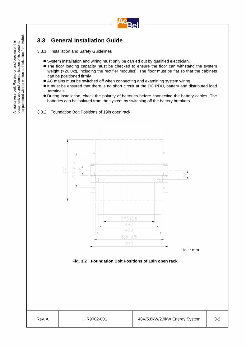
3.3.2 Foundation Bolt Positions of 19in open rack.
Fig. 3.2 Foundation Bolt Positions of 19in open rack
Unit : mm

All
right
s re
serv
ed. P
assi
ng o
n an
d co
pyin
g of
this
do
cum
ent,
use
and
com
mun
icat
ion
of it
s co
nten
ts
not p
erm
itted
with
out w
ritte
n au
thor
izat
ion
from
AcB
el.
Rev. A
HR9002-001 48V/5.8kW/2.9kW Energy System 3-3
3.4 Connection of Cables 3.4.1 Cable Entry Into System
Incoming AC cables, remote signal (dry contact) cables and outgoing DC cables are to be
terminated at the terminal blocks. Please refer to the Fig.3.3 for the cable connections of the
power shelve.
1 AC Input cables to the AC terminal block 40A/3P. 2 Load(+) and battery(+) cables to the DC(+) output terminal block. 3 Dry contact cables to the dry contact terminal block 10A/12P. 4 Load(-) and battery(-) cables to the DC(-) output terminal block.
3.4.2 Connection of AC Input and Ground Cables For single phase input, incoming AC cables are to be terminated at the AC input terminal block., which is as shown in Fig. 3.5 below: -
Fig. 3.3 Cables Connections
Fig. 3.4 AC input terminal block connection for single phase system
BACK VIEW
NG L
AC INPUT
NCCOMNO
AC Fail
LVDS AlarmLV Alarm
COMNO
Common Alarm
NCCOMNONONC COM NC
DC(+) OUTPUT
L4+B1+B2+ L3+ L2+ L1+
DC(-) OUTPUT
L4-B1-B2- L3- L2- L1-
1
3 2
4
NG L
AC INPUT
NCCOMNO
AC Fail
LVDS AlarmLV Alarm
COMNO
Common Alarm
NCCOMNONONC COM NC
DC(+) OUTPUT
L4+B1+B2+ L3+ L2+ L1+
DC(-) OUTPUT
L4-B1-B2- L3- L2- L1-
LNG

All
right
s re
serv
ed. P
assi
ng o
n an
d co
pyin
g of
this
do
cum
ent,
use
and
com
mun
icat
ion
of it
s co
nten
ts
not p
erm
itted
with
out w
ritte
n au
thor
izat
ion
from
AcB
el.
Rev. A
HR9002-001 48V/5.8kW/2.9kW Energy System 3-4
3.4.3 Connection of Load Cables Incoming Load cables are to be connected to the DC output terminal block. Positive load cables are to be terminated at the common (+) and negative load cables are to be terminated at the load (-) DC output terminal blocks, The connection of Load cables as shown in Fig. 3.6 respectively below: -
3.4.4 Connection of Battery Cables Positive battery cables are to be connected to the battery (+) terminal block and negative battery cables are to be connected to the battery (-) terminal block. The connection of battery cables is as shown in Fig. 3.7 below: -
Fig. 3.7 Connection for battery cables
Fig. 3.6 Connection for load cables
NG L
AC INPUT
NCCOMNO
AC Fail
LVDS AlarmLV Alarm
COMNO
Common Alarm
NCCOMNONONC COM NC
DC(+) OUTPUT
L4+B1+B2+ L3+ L2+ L1+
DC(-) OUTPUT
L4-B1-B2- L3- L2- L1-
L1-L2-L3-L4-
L1+L2+L3+L4+
NG L
AC INPUT
NCCOMNO
AC Fail
LVDS AlarmLV Alarm
COMNO
Common Alarm
NCCOMNONONC COM NC
DC(+) OUTPUT
L4+B1+B2+ L3+ L2+ L1+
DC(-) OUTPUT
L4-B1-B2- L3- L2- L1-
B1-B2-
B1+B2+

All
right
s re
serv
ed. P
assi
ng o
n an
d co
pyin
g of
this
do
cum
ent,
use
and
com
mun
icat
ion
of it
s co
nten
ts
not p
erm
itted
with
out w
ritte
n au
thor
izat
ion
from
AcB
el.
Rev. A
HR9002-001 48V/5.8kW/2.9kW Energy System 3-5
Caution: Please switch off the battery MCBs before connecting the battery cable. Please confirm whether the polarity of incoming battery cables connected to the
MCBs right or not before this system works. 3.4.5 Connection of Signal Cables Cables of warning signals are to be terminated at the upper terminals of the voltage free relay contact terminal block. There are three contact points for each signal namely the NO, COM and NC. The four dry contact warning signals are arranged in the order of Battery LV Alarm, Common Alarm, AC Fail Alarm and LVDS Alarm. Refer to Fig.3.8 below : - 3.4.6 Temperature Sensors Connection
Attach the temperature sensor on one of the battery blocks. To ensure good contact, clean the surface of the battery before attaching the battery
temperature sensor. Do not use the corrosive solvent during cleaning process.
Fig. 3.8 Voltage free relay contact terminal block
Fig. 3.9 Temperature sensor and cable connection
Adhesive strip
NG LAC INPUT
NCCOMNO
AC Fail
LVDS AlarmLV Alarm
COMNO
Common Alarm
NCCOMNONONC COM NC
DC(+) OUTPUT
L4+B1+B2+ L3+ L2+ L1+
DC(-) OUTPUT
L4-B1-B2- L3- L2- L1-

All
right
s re
serv
ed. P
assi
ng o
n an
d co
pyin
g of
this
do
cum
ent,
use
and
com
mun
icat
ion
of it
s co
nten
ts
not p
erm
itted
with
out w
ritte
n au
thor
izat
ion
from
AcB
el.
Rev. A
HR9002-001 48V/5.8kW/2.9kW Energy System 3-6
3.4.7 Local and Remote Control and Monitoring Communication Link CSM6 provides RS-232 and TCP/IP communication ports for the local and remote control and monitoring function. Local Control and Monitoring : connect a dedicated RS-232 cable to a local PC. Remote Control and Monitoring : (a) Dial-up by using Modem via PSTN (b) TCI/IP connection via Ethernet network Notes: TCP/IP address default setting: 192.168.128.244
TCP/IP port default setting: 4001
CSM6
RS-232
Communication cable
CSM6-2
TCP/IP PortTCP/IP
Communication cable
Fig. 3.10 Local and Remote control and monitoring communication cable connection

All
right
s re
serv
ed. P
assi
ng o
n an
d co
pyin
g of
this
do
cum
ent,
use
and
com
mun
icat
ion
of it
s co
nten
ts
not p
erm
itted
with
out w
ritte
n au
thor
izat
ion
from
AcB
el.
Rev. A
HR9002-001 48V/5.8kW/2.9kW Energy System 3-7
3.5 Rectifier Installation Unpack the rectifier. Insert the rectifier into the rectifier compartment in the power system.
Push the rectifier along the rail in the compartment. The rectifier must be pushed until the
rear side of its front panel fully touches the cabinet. Secure the rectifier onto the power system with retaining screw provided.
Fig. 3.11 Insert rectifier into the rectifier compartment
Fig. 3.12 Tighten the rectifier with retaining screw
Push

All
right
s re
serv
ed. P
assi
ng o
n an
d co
pyin
g of
this
do
cum
ent,
use
and
com
mun
icat
ion
of it
s co
nten
ts
not p
erm
itted
with
out w
ritte
n au
thor
izat
ion
from
AcB
el.
Rev. A
HR9002-001 48V/5.8kW/2.9kW Energy System 3-8
3.6 Final Installation Check Use the checklist below to complete checks before progressing further. Ensure the system is positioned firmly Ensure all specified ground cables are connected and firmly tightened Ensure the ground resistance meets all specified requirements Ensure all AC and DC cable connections are correct and firmly tightened Ensure the battery polarities are correct at all connections Ensure all battery cable connections are firmly tightened Ensure all signal connections are correctly and firmly connected Ensure the correct cable size and number of cables are selected to carry the rated load
correct and to ensure low voltage drop 3.7 System Power Up Procedure Before turning on the AC mains, ensure the following breakers and switches are off : -
AC MCB at the AC PDU Load MCBs at the DC PDU Battery MCBs at the DC PDU
Turn on the AC mains. Measure the AC input voltage at the AC terminal block. Turn on the AC MCB if the input voltage is normal. Set up the system according to the CSM User Manual. Check the system output voltage displayed on the LCD panel of the CSM. Turn on the battery MCB at the DC PDU if the system output voltage is normal. Turn on the load MCBs at the DC PDU. Check the LEDs status on the CSM and rectifiers. (1) No alarm (no red LED lighted) should
occur. (2) Power normal (green LED lighted).

All
right
s re
serv
ed. P
assi
ng o
n an
d co
pyin
g of
this
do
cum
ent,
use
and
com
mun
icat
ion
of it
s co
nten
ts
not p
erm
itted
with
out w
ritte
n au
thor
izat
ion
from
AcB
el.
Rev. A
HR9002-001 48V/5.8kW/2.9kW Energy System 4-1
4. Maintenance & Fault Tracing 4.1 Maintenance Hazardous voltages exist within the system cabinet. Hence, test before touching any
conducting part. Perform regular inspection on the system at time intervals recommended below : -
Check the environmental conditions (temperature, humidity level, air quality, ventilation etc.) every month. Wash the dust filter of the rectifier modules with clean water every month. Check the condition of the fans in the rectifier modules every half a year. Clean the surface of the cabinets once every year.
An example of a maintenance record is given in Appendi 2 of this manual.
4.2 Recommended Spare Parts List
No. Part Description Quantity
1 Rectifier 1 pcs per ≤10 system
2 CSM6-1 1 pcs per ≤20 system
3 CSM6-2 1 pcs per ≤20 system
4.3 Fault Tracing When a fault message is displayed on the LCD panel of the CSM6-1, the following guide can be used for fault tracing : -
Alarm POWM ENVM
Description of Fault Check Items
DCV ▼ AC FQ ▼
LVA AU COMMXX SMR COMMXX
RS-485 communication breakdown between CSM6-1, CSM6-2 or rectifiers.
1. Check if any RS-485(USB line) connector is disconnected.
AC FQ ▼ MAJOR ALARM SMR ALARMXX AC FAIL 01
AC power failure or loss of phase
1. Check if the AC MCCB/MCB is off. 2. Check if AC power failure or loss of
phase occurs.
- - - SMR ALARMXX Rectifier fault or failure
1. Check if AC power failure or loss of phase occurs.
2. Check if any rectifier fails. 3. Check if the AC INPUT switch of any
rectifier is off or tripped. When the AC INPUT switch of a rectifier is off, its LCD will continue to display the output bus voltage. However, the green LED on the rectifier will be off and the red LED will be on.

All
right
s re
serv
ed. P
assi
ng o
n an
d co
pyin
g of
this
do
cum
ent,
use
and
com
mun
icat
ion
of it
s co
nten
ts
not p
erm
itted
with
out w
ritte
n au
thor
izat
ion
from
AcB
el.
Rev. A
HR9002-001 48V/5.8kW/2.9kW Energy System 4-2
4. Check if the DC OUTPUT switch of any rectifier is off or tripped.
5. Check if the address of any rectifier is incorrectly set.
6. Check if any rectifier is in OCP, OTP, OVP or UVP mode by observing whether the red LED on any rectifier is on or any fault message is displayed on the LCD of any rectifier. Refer to the Rectifier User Manual for more details.
DCV ▲ - - - DC output voltage high 1. Check if the DC output voltage is
higher than the preset DCV▲ alarm level in the CSM “ALMS” subscreen.
DCV ▼ MAJOR ALARM SMR ALARMXX
DC output voltage low, battery voltage low
1. Check if the DC output voltage is lower than the preset DCV ▼ alarm level in the CSM “ALMS” subscreen.
2. Check if the battery is discharged to a voltage lower than the preset DCV ▼ alarm level in the CSM “ALMS” subscreen during an AC failure.
DCV ▼ LVA
MAJOR ALARM SMR ALARMXX
DC output voltage low, battery voltage low.
1. Check if the DC output voltage is lower than the preset LVA alarm level in the CSM “ALMS” subscreen.
2. Check if the battery is discharged to a voltage lower than the preset LVA alarm level in the CSM “ALMS” subscreen during an AC failure.
ETEMPxx ▲ BTEMPxx ▲
- - - Internal ambient / battery temperature high
1. Check if the internal ambient / battery temperature is higher than the preset TEMP ▲ alarm level in the CSM “ALMS” subscreen.
- - - LOAD MCBXX
BATT MCBXX Load or battery MCBs tripped and opened
1. Check if any load or battery MCB on the DCPDU is tripped or open.
- - - LVDSxx LVDS tripped 1. Check if the LVDS is off, tripped or
fail.
Arresters damage checking procedure Whenever a lightning surge occurs and causes damage to the surge arrester at the site AC mains distribution board, check is to be conducted on the SPD on the rectifier system, if a SPD is fractured or shattered, replace it with a new one.

All
right
s re
serv
ed. P
assi
ng o
n an
d co
pyin
g of
this
do
cum
ent,
use
and
com
mun
icat
ion
of it
s co
nten
ts
not p
erm
itted
with
out w
ritte
n au
thor
izat
ion
from
AcB
el.
Rev. A
HR9002-001 48V/5.8kW/2.9kW Energy System 4-3
4.4 Replacing The Rectifier Procedure 4.4.1 Removing a rectifier
. Loosen the rectifier retaining screw.
Pull out the rectifier.
Fig. 4.1 Loosen the rectifier retaining screw
Fig. 4.2 Pull out the rectifier
Pull

All
right
s re
serv
ed. P
assi
ng o
n an
d co
pyin
g of
this
do
cum
ent,
use
and
com
mun
icat
ion
of it
s co
nten
ts
not p
erm
itted
with
out w
ritte
n au
thor
izat
ion
from
AcB
el.
Rev. A
HR9002-001 48V/5.8kW/2.9kW Energy System 4-4
4.4.2 Inserting a rectifier
Insert the new rectifier with the burst-out guides in the shelf.
Push the rectifier along the rail in the compartment. The rectifier must be pushed until the
rear side of its front panel fully touches the cabinet. Secure the rectifier onto the power system with retaining screw on the front panel.
Check the LEDs status on the CSM and rectifiers. (1) No alarm (no red LED lighted) should occur. (2) power normal (green LED lighted).
Fig. 4.3 Insert the new rectifier
Fig. 4.4 Tighten the rectifier with retaining screw
Push

All
right
s re
serv
ed. P
assi
ng o
n an
d co
pyin
g of
this
do
cum
ent,
use
and
com
mun
icat
ion
of it
s co
nten
ts
not p
erm
itted
with
out w
ritte
n au
thor
izat
ion
from
AcB
el.
Rev. A
HR9002-001 48V/5.8kW/2.9kW Energy System 5-1
5. Important Notices 5.1 General Guidelines The following guidelines must be observed during system installation, system operation or when maintenance work is carried out. 5.1.1 Installation
System installation must only be carried out by qualified personnel. Ground resistance must meet local requirements. Any equipment connected to the system must be properly grounded. The conductors connecting external surge arresters must be as short as possible and the
resistance must be less than 10Ω. If metal tube is used to protect the conductors, both sides of the tube must be properly grounded. External surge arresters must be located far from inflammable materials. For safety
reasons, surge arresters must be installed in protective case. The distance between any metallic part and exposed conductor must meet relevant
safety clearance requirements. 5.1.2 System Operation
Before operating the system, it must be ensured that the input voltage, input frequency and other operating conditions are within the specification. The rectifier module must only be operated with its pin housing mated with AMP
211149-1 housing. Refer to the rectifier user manual for more details. When using sealed lead acid batteries, attention must paid to the charge data and
warning notices provided by the battery manufacturer. If any part of the system is damaged, it must undergo maintenance immediately.
5.1.3 Environmental and Airflow Considerations
Operating the system in dusty environment may result in damage. Excessive dust settling inside the rectifier may result in poor heat dissipation and degradation of product performance. It is recommended to operate the system in air conditioned environment. The system must be operated in properly ventilated environment. Do not impede airflow
through the system and rectifier modules by blocking or covering the ventilation holes on the front and back panel of the system. Do not operate the system in environment containing inflammable gas or material. Batteries produce combustible gas. Hence, the room must be properly ventilated.
5.1.4 Maintenance and Repair
Maintenance work must only be carried out by qualified personnel. During maintenance or repair, do not touch any conducting part in the system while the
system is in operation. Before carrying out repair work on the rectifiers, wait for at least 5 minutes after switching
off the power to allow the internal capacitors to discharge.

All
right
s re
serv
ed. P
assi
ng o
n an
d co
pyin
g of
this
do
cum
ent,
use
and
com
mun
icat
ion
of it
s co
nten
ts
not p
erm
itted
with
out w
ritte
n au
thor
izat
ion
from
AcB
el.
Rev. A
HR9002-001 48V/5.8kW/2.9kW Energy System 5-2
5.2 Warranty Constraints This equipment is guaranteed for one year. During the warranty period, the equipment is guaranteed against defective material and faulty manufacture. The equipment has been carefully inspected and undergone comprehensive test at the factory prior to delivery. If, within the warranty period, any material or workmanship related defect is discovered in the equipment, we undertake to make good the defect at our own expense subject to the standard conditions of sale. Our responsibility is in all cases limited to the cost of making good the defect in the equipment itself. The guarantee does not extend to third parties, nor does it apply to defects caused by improper installation, unauthorized alteration, abnormal working conditions, accident, natural disaster, misuse, or wear and tear.

All
right
s re
serv
ed. P
assi
ng o
n an
d co
pyin
g of
this
do
cum
ent,
use
and
com
mun
icat
ion
of it
s co
nten
ts
not p
erm
itted
with
out w
ritte
n au
thor
izat
ion
from
AcB
el.
Rev. A
HR9002-001 48V/5.8kW/2.9kW Energy System
Appendix : 1. Conductor Size Requirement for DC Applications 2. Maintenance Record

All
right
s re
serv
ed. P
assi
ng o
n an
d co
pyin
g of
this
do
cum
ent,
use
and
com
mun
icat
ion
of it
s co
nten
ts
not p
erm
itted
with
out w
ritte
n au
thor
izat
ion
from
AcB
el.
Rev. A
HR9002-001 48V/5.8kW/2.9kW Energy System A-1
1. Conductor Size Requirement for DC Applications
Current Rating (A) Wire Size (mm x mm) Copper Busbar Size (mm x mm)
≤ 20 3.5
30 5.5
40 8
50 ∼ 60 14
70 ∼ 75 22
90 ∼ 100 38
125 50
150 ∼ 175 60
200 80
225 100
250 ∼ 275 125
300 150 or 50 x 2
350 200 or 60 x 2
400 250 or 80 x 2
500 325 or 125 x 2
600 150 x 2 50 x 6t
700 ∼ 800 125 x 3 50 x 10t
1000 150 x 3 60 x 10t
1250 200 x 3 80 x 10t
1600 200 x 4 100 x 10t
2000 2 x 80 x 10t
2500 2 x 100 x 10t
3000 2 x 120 x 10t
4000 3 x 120 x 10t
5000 3 x 150 x 10t Note : Follow local requirements if specified otherwise.

All
right
s re
serv
ed. P
assi
ng o
n an
d co
pyin
g of
this
do
cum
ent,
use
and
com
mun
icat
ion
of it
s co
nten
ts
not p
erm
itted
with
out w
ritte
n au
thor
izat
ion
from
AcB
el.
Rev. A
HR9002-001 48V/5.8kW/2.9kW Energy System A-2
2. Maintenance Record System Serial No. : Month : Inspector :
Date System Alarm Check
EnvironmentalCondition
Check
Dust Filter
Cleaning
Fan Rectifier Check
Cabinet Cleaning
1 2 3 4 5 6 7 8 9 10 11 12 13 14 15 16 17 18 19 20 21 22 23 24 25 26 27 28 29 30 31