eu-us cooperation on satellite navigation
TRANSCRIPT

1
EU-U.S. Cooperation on Satellite Navigation
Working Group C, ARAIM Technical Subgroup
Interim Report
Issue 1.0
December 19th, 2012
The technical information contained in this note does not represent any official U.S. Government, FAA, EU, ESA or EU Member States position or policy. Neither organisation from the U.S. or the EU makes any warranty or guarantee, or promise, expressed or implied concerning the content or accuracy of the views expressed herein. This report only reflects the current status of the ongoing ARAIM discussion in the frame of the EU/U.S. WG-C. Technical aspects will naturally evolve as the work progresses. Any quantitative system characterizations made use of in this report and derived performance estimates are only for ARAIM simulation purposes and need not necessarily represent the performance obtained by the future GNSS systems.

2
Executive Summary
Origin and Objectives of the ARAIM Subgroup The U.S.-EU Agreement on GPS-Galileo Cooperation signed in 2004 established the principles for the cooperation activities between the United States of America and the European Union in the field of satellite navigation. The Agreement foresaw a working group to promote cooperation on the design and development of the next generation of civil satellite-based navigation and timing systems. This work became the focus of Working Group C (WG-C). One of the objectives of WG-C is to develop GPS-Galileo integrated applications for Safety-of-Life services. To this end, WG-C established the ARAIM Technical Subgroup (ARAIM SG) on July 1, 2010. The objective of the ARAIM SG is to investigate ARAIM (Advanced Receiver Autonomous Integrity Monitoring) on a bilateral basis. The further goal is to establish whether ARAIM can be the basis for a multi-constellation concept to support air navigation worldwide. Specifically, ARAIM should support enroute and terminal area flight; it should also support lateral and vertical guidance during approach operations. Amongst these objectives, global vertical guidance for aviation is the most ambitious goal. These aircraft operations are called localizer precision vertical or LPV. LPV-200 indicates that this guidance should support approach operations down to 200-foot altitudes, and the ARAIM SG focuses on ARAIM architectures to support LPV-200 globally. This document is the first milestone report in a three-phase effort. It provides: an ARAIM Overview, Achievements During Phase 1, and Next Steps. This report has been prepared by the ARAIM SG members from the U.S. Federal Aviation Administration (FAA), Stanford University (SU), the MITRE Corporation, Illinois Institute of Technology (IIT), German Aerospace Center (DLR), University FAF Munich (UniBW), the European Space Agency (ESA) and the European Commission (EC). ARAIM Overview As described above, ARAIM must ensure navigation integrity for enroute flight, terminal and approach operations. For the latter, it must detect all hazardous faults in the underlying Global Navigation Satellite Systems (GNSS) within seconds. In the language of air navigation, ARAIM must ensure that the pilot is warned within six seconds of any hazardous misleading information (HMI) before the navigation sensor error is greater than a certain amount (currently 35 meters for LPV-200). Other auxiliary conditions are identified in section 2 of the report. ARAIM is intended to support air navigation for several decades. As such, ARAIM must be flexible, so that air navigation will not have a brittle dependence on the health of the underlying Global Navigation Satellite Systems (e.g. GPS, Galileo, GLONASS, BeiDou/Compass, etc.). Thus, ARAIM must allow new satellites and constellations to come into use by aviators. It must automatically compensate for the fault rates of those new satellites and constellations. These fault rates are expected to be high for new

3
constellations and decrease as the constellation matures. ARAIM must also automatically remove troublesome satellites if they are no longer suitable for air navigation. ARAIM is depicted in Figure 1. It is based on the multiplicity of GNSS constellations shown in the upper left of the figure. The satellite signals are received on the aircraft (blue arrows) and on the ground (red arrows). A reference air algorithm is described in Section 3 of the subject report. This algorithm is based on a residuals test that uses the over-determined nature of the navigation solution to detect and isolate faults contained in the satellite measurements. As such, ARAIM is an advanced version of receiver autonomous integrity monitoring (RAIM), which has been known to the aviation community since the late 1980s. The original version of RAIM was based on a set of fixed assertions regarding the nominal performance and fault rates of the Global Positioning System (GPS). In contrast, ARAIM relies on a ground system to provide periodic updates regarding the nominal performance and fault rates of the multiplicity of contributing constellations. This integrity data is contained in the Integrity Support Message (ISM) that is developed on the ground and broadcast to the airborne fleet. The red arrows in Figure 1 show the development and delivery of the ISM. As shown, an independent reference network shall monitor the participating GNSS constellations. This network must assess the nominal performance and detect faults. Using secure communication lines, it sends this information to the ISM cache. ARAIM requires this monitoring function and data for any GNSS constellation to be used for LPV-200. ARAIM supports a variety of communication links from the ISM cache to the aircraft. For example, it enables the nation-state to draw current ISMs from the cache to support departing or arriving aircraft. The nation-state may choose to broadcast these in the airport area using line-of-sight radio links such as the VHF data broadcast. Alternatively, the nation-state may choose to make the ISMs available continuously throughout its airspace. In this case, it can broadcast the ISMs from a geostationary satellite (e.g. SBAS), a medium Earth orbit satellite (e.g. GNSS) or a low Earth orbit satellite (LEO). The different communication links will be further consolidated during the progress of the work, and the final candidates will depend not only on the suitability of the link but also on the latency allowed by the robustness of GNSS constellations used in ARAIM. For global coverage, ARAIM will enable a set of overlapping Radio Frequency (RF) coverage volumes to allow seamless transition between different operations (e.g. en-route, terminal and precision approach). Within these coverage volumes, nation-state requirements will define service volumes where various performance requirements are guaranteed via approved state procedures. This will likely include a requirement to receive ISM updates from a state within a minimum time prior to executing certain procedures. ARAIM compensates for the delay in the ISM generation and delivery path (red arrows) by relying on the residuals test in the aircraft to detect significant faults quickly. Thus the over-specified nature of a multi-constellation system is leveraged to provide the flexible ISM generation needed to incorporate multiple constellations and multiple delivery protocols.

4
Achievements During Phase One Performance Requirements The ARAIM SG focused on evaluating the feasibility of LPV-200 operations using ARAIM. Section 2 of this report explains how these requirements were interpreted by the ARAIM SG and applied to the present analysis. The requirements include four vertical positioning error criteria at different probability levels ranging from 95% to 99.99999%. The ARAIM SG expended appreciable effort on the interpretation and analysis of these requirements. To date, LPV-200 is only provided by Satellite Based Augmentation Systems (SBAS). Requirements that are readily met by SBAS may not be met by ARAIM, because ARAIM has different error characteristics than SBAS. In fact, SBAS only requires the aircraft to make one test to determine the availability of suitable integrity. This SBAS test examines the so-called Vertical Protection Level (VPL). ARAIM will likely require that the avionics conduct three tests to determine the availability of ARAIM for LPV: the VPL test (99.99999%), the effective monitor threshold test (99.999%) and accuracy test (95% accuracy and 99.99999% fault-free accuracy).
ARAIM Reference Algorithm for the Aircraft
As described in Section 3, the ARAIM reference algorithm for the aircraft can cope with multiple faults. Section 3 also describes the additional availability criteria mentioned above and a preliminary description of the exclusion function. In Section 3, the algorithm is described in the order it is executed, starting with the calculation of the nominal error models and ending with the exclusion function. Section 3 also provides a list of possible
5
improvements that will be considered in the upcoming phase of work. Importantly, the ARAIM reference algorithm described in this report is entirely based on papers that ARAIM SG workers have placed in the public domain. These references are given in Section 3.
Performance Results
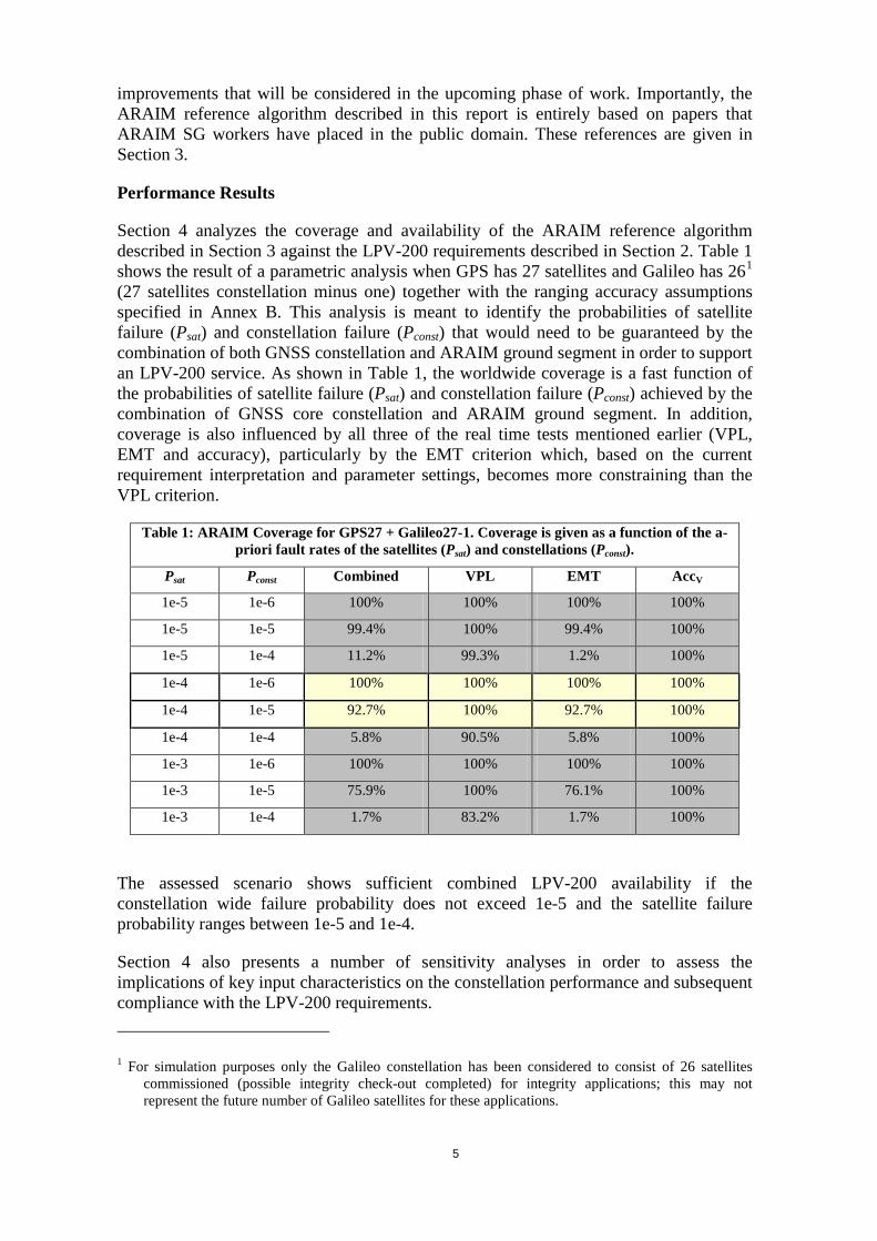
Section 4 analyzes the coverage and availability of the ARAIM reference algorithm described in Section 3 against the LPV-200 requirements described in Section 2. Table 1 shows the result of a parametric analysis when GPS has 27 satellites and Galileo has 261 (27 satellites constellation minus one) together with the ranging accuracy assumptions specified in Annex B. This analysis is meant to identify the probabilities of satellite failure (Psat) and constellation failure (Pconst) that would need to be guaranteed by the combination of both GNSS constellation and ARAIM ground segment in order to support an LPV-200 service. As shown in Table 1, the worldwide coverage is a fast function of the probabilities of satellite failure (Psat) and constellation failure (Pconst) achieved by the combination of GNSS core constellation and ARAIM ground segment. In addition, coverage is also influenced by all three of the real time tests mentioned earlier (VPL, EMT and accuracy), particularly by the EMT criterion which, based on the current requirement interpretation and parameter settings, becomes more constraining than the VPL criterion.
Table 1: ARAIM Coverage for GPS27 + Galileo27-1. Coverage is given as a function of the a-priori fault rates of the satellites (Psat) and constellations (Pconst).
Psat Pconst Combined VPL EMT AccV
1e-5 1e-6 100% 100% 100% 100%
1e-5 1e-5 99.4% 100% 99.4% 100%
1e-5 1e-4 11.2% 99.3% 1.2% 100%
1e-4 1e-6 100% 100% 100% 100%
1e-4 1e-5 92.7% 100% 92.7% 100%
1e-4 1e-4 5.8% 90.5% 5.8% 100%
1e-3 1e-6 100% 100% 100% 100%
1e-3 1e-5 75.9% 100% 76.1% 100%
1e-3 1e-4 1.7% 83.2% 1.7% 100%
The assessed scenario shows sufficient combined LPV-200 availability if the constellation wide failure probability does not exceed 1e-5 and the satellite failure probability ranges between 1e-5 and 1e-4.
Section 4 also presents a number of sensitivity analyses in order to assess the implications of key input characteristics on the constellation performance and subsequent compliance with the LPV-200 requirements. 1 For simulation purposes only the Galileo constellation has been considered to consist of 26 satellites
commissioned (possible integrity check-out completed) for integrity applications; this may not represent the future number of Galileo satellites for these applications.

6
Alignment of Simulation Tools Different service volume simulation software tools exist at the ARAIM SG participating entities: Stanford University, Illinois Institute of Technology, European Space Agency, German Aerospace Center and the University FAF Munich. Fortunately, these tools are independent. In order to establish a common reference for future ARAIM development, these tools were crosschecked. As described in Section 4, this crosscheck was successful. This crosscheck also fostered an information exchange on ARAIM and the interpretation of its input parameters and assumptions. ARAIM Threats Section 5 lists and characterizes the navigation threats (feared events) that would be hazardous to a GNSS based service for worldwide LPV-200. Navigation threats are considered to be all possible events (i.e. of natural, systemic or operational nature) that can cause the computed navigation solution to deviate from the true position, regardless of whether a specific fault can be identified in one of the navigation systems or not. ARAIM threats are those which can impact the performance of the ARAIM algorithm and whose probability of occurrence is larger than a required integrity risk.
Section 5 includes the identification of threats and their classification into different categories. It identifies the following ARAIM threat classes: satellite clock and ephemeris, signal deformation, code-carrier incoherence, inter-frequency bias, satellite antenna bias, ionospheric, tropospheric, and receiver noise and multipath. Section 5 also partitions the entire threat space into: a nominal error model, plus an uncorrelated fault / residual error per satellite. The remaining correlated and uncharacterized errors can all be grouped into a final “wide fault” subset. Section 5 applies this partition to the fault classes listed above, and provides a comprehensive threat table (Table 5.2). This table also provides preliminary information on the magnitude and onset probability of the threats that needs to be further consolidated.
Next Steps
In the next phase, the ARAIM SG will sharpen the current description of ARAIM. After all, Figure 1 may allow many different system implementations. Table 2 describes the breadth of the possible ARAIM trade space.
It shows that the ARAIM SG must make decisions about: the span and multiplicity of the monitoring networks; the bounding strategy used by the ground network; assertions regarding constellation (wide) faults; the contents of the ISM; the concept of operation for the delivery of the ISM to the aircraft; and the overall time from fault onset to the delivery of the ISM to the aircraft (time-for-ISM alert or TIA).
Table 2 constitutes a nearly unmanageably large set of alternatives. To provide a manageable path forward, three ARAIM representatives were posited that are based on the time-for-ISM-alert (TIA). These alternatives are: rapid time-to-alert (TIA of minutes to hours); offline monitoring (TIA of one day or more); and rapid time-to-alert for arrivals. The ARAIM SG keyed on TIA, because it is directly connected to the constellation-wide failures that have proven to be the most nettlesome aspect of ARAIM development. Thus, the above listed ARAIM representatives will allow us to more deeply understand our sensitivity to constellation-wide threats, and illuminate the best way forward. This set of ARAIM representatives will be augmented or modified as facts

7
reveal themselves. With these representatives, the ARAIM SG will perform the tasks described below.
Table 2: Summary of ARAIM Trade Space Ground Monitoring Network. The density of the ground system needed to support ARAIM can vary from sparse to dense. It can also span the globe or be confined to single sites. This reference network may be purpose built for ARAIM or drawn from existing SBAS or GNSS networks. Bounding Methodology. Our bounding methodology is categorized by the amount of time that the monitors collect data before updating their estimates of the GNSS constellation health. The ground monitors may be allowed to collect data for one or more days before updating estimates. On the other hand, the ground network may be required to conduct more rapid bounding of these parameters. Assertions Regarding Constellation Faults (i.e. wide faults). The wide faults may be associated with a variety of assertions. These assertions range from: wide faults do not exist to wide faults can simultaneously effect more than one constellation. Content of the Integrity Support Messages (ISM). The ISM may use only one bit per satellite to state whether that satellite is suitable for use. At the other extreme, it may broadcast a full set of replacement parameters for the ephemeris of every useable satellite. Concept of ISM Operation. The ISM may be broadcast continuously to the fleet (e.g. broadcast from SBAS or GNSS). Near the other extreme, it may only reach the aircraft at the time of dispatch. Time Between Integrity Support Messages (i.e. Time to ISM Alert, TIA). The TIA measures the end-to-end delay from the onset of an integrity fault to the alert in the aircraft. As such, it is strongly connected to the bounding methodology and the concept of ISM operation. Performance Evaluation. The ARAIM SG shall conduct an end-to-end evaluation inclusive of the reference ARAIM algorithm and the ISM message associated with each of the ARAIM representatives described above. If warranted, the Working Group shall use actual GPS and GLONASS measurements to validate the various designs. The results shall be evaluated in the user position domain and used to evaluate integrity risk and availability for each ARAIM representative.
Maturation of GNSS Threat Characterization. The ARAIM SG shall mature the preliminary characterization presented herein (Table 5.2). They shall scrutinize the preliminary threat space partition (nominal, uncorrelated, and wide faults). They shall also conduct analyses and use engineering judgment to mature the present information on the magnitude and onset probability of the listed threats. The threat dynamic may be also subject of further analysis. ARAIM Threat Allocation and Mitigation. The ARAIM SG shall allocate the identified threats to the different ARAIM system elements (GNSS space segment, GNSS ground segment, user segment, ARAIM ground segment) and identify corresponding threat mitigations. This allocation shall be conducted for the ARAIM representatives.
Definition of Ground Monitoring. The ARAIM SG shall propose, study and recommend ground monitoring approaches for each ARAIM representative. For each of the ARAIM representatives, the SG shall determine the most likely reference network properties including: the number of stations, the geographical spread of the network, and the level of redundancy and reliability at each station. The SG shall also consider the operation and maintenance of the network. The SG shall recommend whether the ground networks must be dedicated to ARAIM, or might be shared with other systems.
Definition of ISM Requirements. The ARAIM SG shall analyze ISM content for each of the ARAIM representatives. In each case, one or two broadcast channels shall be considered for the ISM design. For example, SBAS and suitable GNSS data channels

8
(e.g. L5/E5a or L1C/E1OS) are reasonably associated with the rapid TISM class, because the connectivity is continuous.

9
TABLE OF CONTENTS
0 INTRODUCTION AND PURPOSE ......................................................................... 13
1 ARAIM WORKING ASSUMPTIONS..................................................................... 14
1.1 ARAIM Concept ............................................................................................. 14 1.2 GEAS Phase II Report Assumptions ............................................................... 15 1.3 Operational Goals ............................................................................................ 17 1.4 Subsystem Roles and Responsibilities ............................................................ 18 1.5 Minimum Constellation Requirements ............................................................ 19
2 PERFORMANCE REQUIREMENTS ...................................................................... 19
3 ARAIM USER ALGORITHMS AND IMPROVEMENTS ..................................... 22
3.1 Reference Solution Separation ARAIM Algorithm ........................................ 22 3.1.1 List of inputs ...................................................................................... 22 3.1.2 List of constants ................................................................................. 23 3.1.3 Pseudorange covariance matrices Cint and Cacc ................................. 24 3.1.4 All-in-view position solution ............................................................. 24 3.1.5 Determination of the faults that need to be monitored and the
associated probabilities of fault ......................................................... 25 3.1.6 Fault-tolerant positions and associated standard deviations
and biases ........................................................................................... 26 3.1.7 Solution separation threshold tests and chi-square test ..................... 27 3.1.8 Protection Levels ............................................................................... 28 3.1.9 Accuracy, the fault free position error bound, and Effective
Monitor Threshold ............................................................................. 29 3.1.10 Fault exclusion (preliminary) ............................................................ 29 3.1.11 Monitoring previously excluded satellites (preliminary) .................. 30
3.2 List of possible improvements......................................................................... 30 3.2.1 Improvements in the calculation of the Protection Level .................. 30 3.2.2 Threat model modifications ............................................................... 31 3.2.3 Ground validated long term ephemeris for EOP fault
mitigation ........................................................................................... 32 3.2.4 Improvements in the position solution .............................................. 33 3.2.5 Test simplification ............................................................................. 33
4 PERFORMANCE EVALUATION. ......................................................................... 35
4.1 Scenario Definition .......................................................................................... 35 4.1.1 GNSS Constellation Characteristics .................................................. 35 4.1.2 User Ranging Characteristics ............................................................ 36 4.1.3 Satellite Fault and Constellation Fault Probabilities ......................... 36 4.1.4 Requirements ..................................................................................... 36
4.2 Performance Prediction ................................................................................... 36 4.3 Simulation Tool Crosscheck............................................................................ 39

10
4.3.1 Scenario Definition ............................................................................ 39 4.3.2 Crosscheck Results ............................................................................ 39
5 ARAIM THREATS ................................................................................................... 41
5.1 ARAIM Threat Identification .......................................................................... 41 5.1.1 Satellite Clock and Ephemeris Threats .............................................. 43 5.1.2 Signal Deformation Threats .............................................................. 44 5.1.3 Code-Carrier Incoherence Threats .................................................... 44 5.1.4 IFB Threats ........................................................................................ 45 5.1.5 Antenna Bias Threats ........................................................................ 45 5.1.6 Ionospheric Threats ........................................................................... 45 5.1.7 Tropospheric Threats ......................................................................... 46 5.1.8 Receiver Noise and Multipath Threats .............................................. 46
5.2 ARAIM Threat Characterization ..................................................................... 46
6 PROGNOSIS FOR ARAIM ...................................................................................... 48
7 NEXT STEPS ............................................................................................................ 50
7.1 The next section describes the ARAIM representatives. ARAIM Representatives ................................................................................................ 50
7.2 Next Tasks ....................................................................................................... 54
ANNEX A: LIST OF REFERENCES .............................................................................. 57
ANNEX B: ERROR MODELS ........................................................................................ 63
ANNEX C: METHOD TO SOLVE PL EQUATION ....................................................... 65
ANNEX D: CHARACTERIZATION OF ARAIM ARCHITECTURES ........................ 66
D.3.0 ANNEX E: TASKS COMPLETED PRIOR TO JUNE 2012 ......................... 71
ANNEX F: TASKS TO BE COMPLETED AFTER JUNE 2012 .................................... 72
F.1 - Tasks to be completed between June 2012 and June 2013 [TBC] ................... 72 F.2 - Tasks to be completed between June 2013 and December 2013 [TBC] .......... 72
ANNEX G: MILESTONES .............................................................................................. 72
ANNEX H: THREAT CHARACTERISATION TABLE ................................................ 73
11
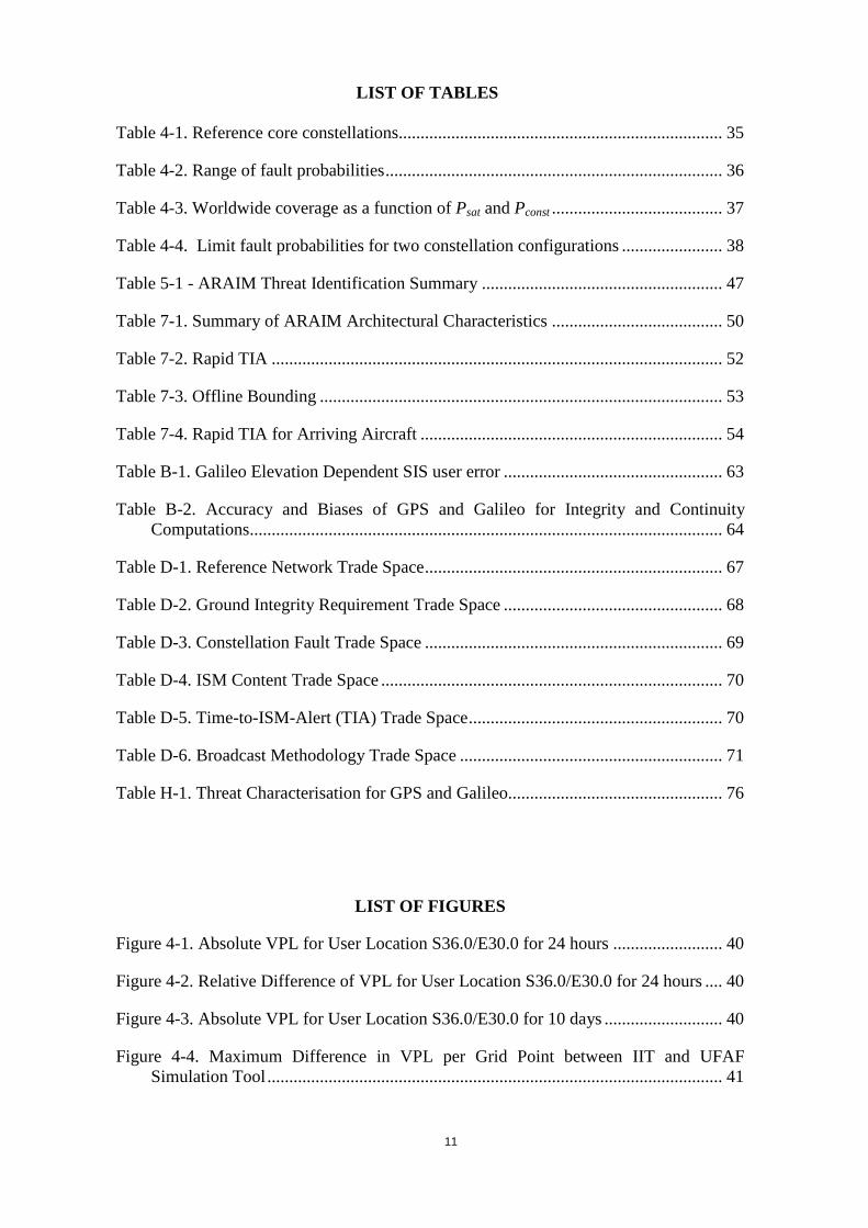
LIST OF TABLES
Table 4-1. Reference core constellations.......................................................................... 35
Table 4-2. Range of fault probabilities ............................................................................. 36
Table 4-3. Worldwide coverage as a function of Psat and Pconst ....................................... 37
Table 4-4. Limit fault probabilities for two constellation configurations ....................... 38
Table 5-1 - ARAIM Threat Identification Summary ....................................................... 47
Table 7-1. Summary of ARAIM Architectural Characteristics ....................................... 50
Table 7-2. Rapid TIA ....................................................................................................... 52
Table 7-3. Offline Bounding ............................................................................................ 53
Table 7-4. Rapid TIA for Arriving Aircraft ..................................................................... 54
Table B-1. Galileo Elevation Dependent SIS user error .................................................. 63
Table B-2. Accuracy and Biases of GPS and Galileo for Integrity and Continuity Computations ............................................................................................................ 64
Table D-1. Reference Network Trade Space .................................................................... 67
Table D-2. Ground Integrity Requirement Trade Space .................................................. 68
Table D-3. Constellation Fault Trade Space .................................................................... 69
Table D-4. ISM Content Trade Space .............................................................................. 70
Table D-5. Time-to-ISM-Alert (TIA) Trade Space .......................................................... 70
Table D-6. Broadcast Methodology Trade Space ............................................................ 71
Table H-1. Threat Characterisation for GPS and Galileo................................................. 76
LIST OF FIGURES
Figure 4-1. Absolute VPL for User Location S36.0/E30.0 for 24 hours ......................... 40
Figure 4-2. Relative Difference of VPL for User Location S36.0/E30.0 for 24 hours .... 40
Figure 4-3. Absolute VPL for User Location S36.0/E30.0 for 10 days ........................... 40
Figure 4-4. Maximum Difference in VPL per Grid Point between IIT and UFAF Simulation Tool ........................................................................................................ 41

12

13
0 INTRODUCTION AND PURPOSE
The U.S.-EU Agreement on GPS-Galileo Cooperation signed in 2004 established the principles for the cooperation activities between the United States of America and the European Union in the field of satellite navigation. The Agreement foresaw "a working group to promote cooperation on the design and development of the next generation of civil satellite-based navigation and timing systems", which is the focus of Working Group C. One of the objectives of Working Group C is to develop GPS-Galileo integrated applications for Safety-of-Life services and describe their performances. Within this context, on 1st July 2010 the Group established the ARAIM Technical Subgroup (ARAIM SG), with the mandate to investigate ARAIM (Advanced Receiver Autonomous Integrity Monitoring) on a bilateral basis and the objective of defining a reference multi-constellation ARAIM concept allowing vertical guidance (LPV, LPV-200 and beyond). The ARAIM SG, in its Terms of Reference [RD-01], defined a work schedule including a set of tasks and three milestones with the aim to accomplish its objective by the end of 2013 [TBC]. This Interim Report corresponds to Milestone 1, which is associated to the completion of the following tasks:
• Task 0: Performance Requirements • Task 1: ARAIM User Algorithms and Improvements • Task 2: Performance Evaluation (partially) • Task 3.1: ARAIM Threat Identification • Task 3.2: ARAIM Threat Characterisation (partially)
The next tasks foreseen in the Terms of Reference that will be finalised in the next milestones are:
• Task 2: Performance Evaluation (completion) • Task 3.2: ARAIM Threat Characterisation (partially) • Task 3.3: ARAIM Threat Allocation and Mitigation Identification • Task 4: ISM Generation, Design and Dissemination • Task 5: Ground Monitoring • Task 6: Relationship ARAIM/SBAS • Task 7: Roadmap • Task 8: Report
In the following section, the document presents the ARAIM working assumptions and constraints used by the group. The next sections report on the progress for each of the tasks linked to Milestone 1 (Task 0 to Task 3.2). At the end of the document, a section called 'Next Steps' presents the work performed to date for the rest of the tasks (the remaining Task 2 and Task 4 to Task 8) as well as the activities foreseen, and proposes a framework based on different ARAIM classes for the next phases. It should be noted that Task 1 (ARAIM User Algorithms and Improvements) is considered as 'completed' for Milestone 1 in the sense that a reference user algorithm including some recommendations for improvements is already proposed. However, the ARAIM SG will continue working

14
on ARAIM user algorithm improvements derived from the remaining tasks of the work plan before any proposal for user avionics standardisation is made. It needs to be noted that this report recalls the current status of the work conducted by the group and that further work will be carried out in the next period of time which might also re-visits some of the statements given in this report. Therefore it can not be excluded that the final report will differ in some aspects from this Interim Report. This document has been prepared by the ARAIM SG with the contributions of the US Federal Aviation Administration (FAA), Stanford University (SU), the MITRE Corporation, Illinois Institute of Technology (IIT), German Aerospace Center (DLR), University FAF Munich (UniBW), CNES, the European Space Agency (ESA) and the European Commission (EC).
1 ARAIM WORKING ASSUMPTIONS
This section identifies the basic ARAIM concept and the assumptions used by the ARAIM SG to develop the concepts, analysis, and preliminary conclusions discussed within this report. The ARAIM concept was originally proposed within the U.S. GPS Evolutionary Architecture Study (GEAS) report [RD-02]. The GEAS results and conclusions were reviewed and incorporated into the ARAIM SG’s own work.
1.1 ARAIM Concept
As specified in the GEAS report and envisioned by the ARAIM SG, ARAIM contains three system segments: airborne, space and ground [RD-03]. The airborne segment contains algorithms that are based upon current Receiver Autonomous Integrity Monitoring (RAIM) algorithms. Measurement redundancy is used to identify and remove inconsistent satellite range estimates. Confidence bounds are formed around the position estimate based upon different subset position solutions and specified performance parameters for the measurements that are found to be consistent. The space segment consists of one or more constellations of global navigation satellites. The satellites are assumed to comply with a certain level of performance that may be specific to each constellation or even satellite. Finally, unlike today’s RAIM, there is a ground segment to assure that the assumed levels of performance continue to be met. The ARAIM ground segment may consist of monitoring reference stations, a central collection and decision-making entity (i.e. to verify constellation and satellite performance), and a data channel to the aircraft to communicate information about each satellite. ARAIM is intended to operate similar to RAIM, but there are some very key differences that arise from the higher level of accuracy and integrity required for the intended operation. RAIM provides only horizontal guidance and provides protection regions that are measured in hundreds of meters. Therefore, RAIM has only one significant threat to consider: a large-scale clock/ephemeris error on any one of the satellites in view. All other error sources are too small to threaten such a large protection radius. ARAIM seeks to provide vertical guidance and its accuracy must be better than 4 meters and its protection bound is measured in tens of meters. Therefore, there are many more threats that can make ARAIM performance unacceptable. Further, the consequences of exceeding the position bound are much more significant for the intended ARAIM operations than for lateral navigation as supported by RAIM. ARAIM will also make use of dual-frequency pseudorange measurements for an ionosphere-free position solution.

15
This removes the first order ionospheric delay effect and eliminates a very significant threat source. Section 2 of this report describes the performance requirements to support LPV-200 in more detail. The smaller integrity limits, tighter accuracy requirements, and more stringent design assurance level all lead to a need to more carefully evaluate the potential fault modes and airborne algorithm for mitigating their effect. Section 5 provides details about the threats that ARAIM must consider. These are the same threats that can affect other satellite radio navigation systems designed to meet vertical guidance such as Satellite Based Augmentation Systems (SBAS) and Ground Based Augmentation Systems (GBAS). Section 3 describes an example airborne algorithm to mitigate the effects of these threats. Although it shares much in common with conventional RAIM, there are also many additional components to address the additional threats and more stringent requirements. The final piece is the assured performance level of the satellites, given constellation service provider commitments and ground monitoring (core-constellation but more specifically ARAIM dedicated ground monitoring). This is a topic of study for the upcoming year. Section 4 provides ARAIM performance results for a range of possible values. However, it is yet to be determined which values are likely to be supported and how best to achieve the monitoring. Section 6 describes some of the preliminary work done in this area and outlines the next steps to further investigate this issue. To summarize the concept: one or more constellations will provide satellite ranging measurements that meet a minimum level of performance. There will be an ARAIM ground monitoring network to observe these satellites and identify which satellites are suitable for use and at what level they are performing. This information will be transmitted to the aircraft as part of an Integrity Service Message (ISM). The aircraft will use this information to determine which combinations of satellite faults must be checked and to what probability of missed detection. The ARAIM algorithm will then evaluate all of the relevant subsets, appropriate position estimates and integrity bounds. Any erroneous satellite measurements will be identified and isolated from further use.
1.2 GEAS Phase II Report Assumptions
This section includes important assumptions originally developed by the GEAS group and documented in their Phase II report. Assumptions critical to the ARAIM SG work are reproduced and summarized here to highlight these dependencies. In some cases, the original GEAS assumptions were modified based on ARAIM SG discussions and conclusions.
Satellite Ranging Error Characteristics Historically, fault-free satellite ranging errors have been characterized using overbounding, zero-mean Gaussian distributions to bound their effect on SBAS guidance. ARAIM will additionally accommodate nominal, non-zero mean Gaussian errors to more accurately reflect the actual satellite errors.
User Range Error (URE)/Signal in Space Error (SISE) The URE/SISE is the standard deviation of a Gaussian error distribution modelling the range component of the signal-in-space error, suitable for the evaluation of system accuracy and continuity performance.

16
User Range Accuracy (URA)/Signal in Space Accuracy (SISA) URA/SISA is the standard deviation of a Gaussian error distribution that bounds the distributions of the range component of signal-in-space error in the absence of a fault condition and is used to evaluate availability of the integrity monitoring function.
Nominal Bias in Range Measurements The GEAS Phase II report allowed for the possibility of fault-free biases, both to account for near-constant uncorrected errors (signal deformation and antenna biases) and non-Gaussian behaviour. With respect to availability assessments, the ARAIM SG will use similar assumptions used by the GEAS.
Probability of Satellite Fault (Psat) In certain states, a satellite may not be well described by the combination of the maximum and nominal biases, the URE/SISE, and the URA/SISA. It may have a larger bias or a higher probability of larger error. Psat describes the probability that the four parameters will not correctly describe the satellite’s current expected error distribution. This fault probability applies to a specific satellite, and it is used to describe faults that occur independently on each satellite relative to any other.
Probability of Constellation Fault (Pconst) There is also a probability that an error could lead to faults on multiple satellites within a constellation due to a common cause. Pconst describes the probability that URE/SISE, URA/SISA and maximum nominal bias will not correctly describe the current expected error distribution for more than one satellite simultaneously within a constellation.
Airborne Error Model In addition to URA/SISA or URE/SISE, the error in the user receiver range measurement includes tropospheric error, airborne multipath error, and user receiver noise. These models are described in [RD-04], [RD-05] and summarized in Annex B.
Satellite Integrity Fault Models The GEAS Phase II report focused its analysis on known GPS faults and assumed prior probability faults consistent with that system. The ARAIM SG has expanded its analysis to include Galileo threats and defined the threat in a manner which could be extended to cover also GLONASS and other GNSS constellations planned for International Civil Aviation Organization (ICAO) standardization (e.g. BeiDou). The group has defined a set of high-level threat categories, which are traceable to Galileo and GPS faults. These threats and the associated prior probability assumptions used as working assumptions by the group are detailed in subsequent sections.
Integrity Risk Allocation

17
For classical RAIM, the allowed probability of HMI requirement (P{HMI}) is allocated equally among faults for all satellites in view. The probability of a hazardous fault-free error and the probability of multiple satellite faults are neglected. From this previous work, the conditional probability of a missed detection (Pmd) requirement of 0.001 was derived assuming a P{HMI} requirement of 10-7 and a fault a priori probability of 10-4/hr for the set of satellites used in the user position solution.
In contrast, for ARAIM, the probability of a hazardous fault-free position error and the probability of multiple faults are not neglected. The fault-free error is given an allocation and multiple faults may have to be monitored by the receiver. The total allowable P{HMI} requirement is allocated among the fault-free case and all the faulted cases. The Pmd concept used by classical RAIM algorithms are no longer needed in the context of the ARAIM algorithm described in Section 3. Since in ARAIM flexible integrity allocations are employed in computing a VPL, regardless of whether detection takes place or not, the corresponding concept employed in the framework of multiple hypothesis solution separation ARAIM algorithms is the “integrity risk (PHMI) allocation”.
The fault-free case: This case covers the causes of HMI that are due to large random errors that can occur with small probability in the normal operation of the system, such as those caused by receiver noise, multipath and inaccurate tropospheric delay estimation along with an unfortunate combination of bias errors.
The faulted cases can be divided in two classes: independent faults – single or multiple satellite faults due to simultaneous independent satellite faults, and correlated faults –multiple simultaneous satellite faults due to a common cause:
Independent faults: These are satellite faults that do not have a common cause. ARAIM accounts for the possibility of single or multiple independent satellites faults occurring simultaneously, even across different constellations.
Correlated faults: This may occur because a single faulted action at the satellite constellation control segment can lead to simultaneous faults on multiple satellites. Other potential causes for correlated faults may intrinsically lie within identical blocks of hardware or software aboard the satellites.
In all faulted cases, the integrity risk is the product of the assumed prior probability of a fault, and the conditional probability that it is not detected by ARAIM and causes HMI to be passed to the user. The explicit consideration of multiple satellite faults is the most significant change with respect to the ARAIM concept outlined in the GEAS Phase II report.
1.3 Operational Goals
ARAIM is an airborne application supported by the satellite and ground infrastructure intended to ensure navigation integrity for various aircraft operations. It is capable of supporting global operations across many States, constellations and service providers. This current report focuses on evaluating the feasibility of LPV-200 operations [RD-02]. These operations are considered the most stringent precision approach operations currently supported by SBAS and provide a useful measure of ARAIM performance. Performance targets for LPV-200 were proposed at the ICAO and adopted as guidance material to Annex 10, Amendment 85. Section 2 of this report explains how these requirements were interpreted by the ARAIM SG and applied to the present analysis.

18
The ARAIM concept relies on ground infrastructure to periodically update the aircraft of certain key performance assumption. These updates will take the form of an Integrity Support Message (ISM); however, the mechanisms and interfaces for delivering to the aircraft have yet to be determined. Possible dissemination mechanisms could include ground transmitters, satellite links or aircraft data links. For ARAIM to remain a truly global concept, a range of complimentary mechanisms with overlapping RF coverage volumes will likely be necessary to allow seamless transition between different operations (e.g. en-route, terminal and precision approach). Within these coverage volumes, state requirements will define service volumes where various performance requirements are guaranteed via approved state procedures. This will likely include a requirement to receive ISM updates from a state within a minimum rate prior to executing certain procedures.
1.4 Subsystem Roles and Responsibilities
Aircraft ARAIM will operate in a similar manner as traditional RAIM. It includes an avionics function implemented on the aircraft being the real-time source of mitigation against faults. The proposed reference algorithm is based on a Solution Separation (SS) approach. For each possible fault, a subset solution is computed and compared to the all-in-view position solution. If this difference is within a predetermined threshold, a Protection Level is computed. Otherwise, exclusion is attempted. This method is discussed further in the Section 3 of this document.
The aircraft algorithm is responsible for meeting the integrity and continuity targets necessary to mitigate each fault. However, it is expected the aircraft will achieve this by relying on certain assumptions about the faults through the ISM, where the ISM will most likely be provided by from the Air Navigation Service Providers (ANSPs) in coordination with the GNSS System Operator. These assumptions and external inputs may take different forms.
GNSS Satellites and Constellation GNSS Systems supporting ARAIM will broadcast an Annex 10 compliant signal-in-space (SIS) that meets certain minimum performance requirements. Specific integrity and continuity probabilities will be required for global ARAIM, implying this specific ARAIM System requirements including the potential for additional ground monitoring infrastructure to verify satellite and constellation performance. Certain architectures variants being considered involve broadcasting the ISM over a GNSS constellation. This would effectively incorporate some responsibilities of the ANSP into the GNSS constellation and/or the ARAIM ground monitoring infrastructure.
Ground Monitoring GNSS-external ground monitoring will likely be necessary to verify GNSS System performance assumptions. As mentioned above, the results of ground monitoring will be broadcast to the aircraft via the ISM. These functions maybe achieved by a variety of means and are discussed briefly in Section 6. The actual capability of a GNSS-external ground monitoring to verify GNSS System performance assumptions is to be evaluated as part of the ARAIM SG. Further definition of ground monitoring functions and their requirements are the subject of future work by the ARAIM SG.
19
1.5 Minimum Constellation Requirements
In general, the GEAS Phase II results have shown that two constellations are likely required to meet minimum availability requirements globally for LPV-200 using ARAIM. It may be possible to support ARAIM with a single constellation; however, this would only be possible with a robust constellation (> 30 satellites in optimized orbital geometry) and would assume that the probability of constellation wide faults (i.e. Pconst) are below the total allowable integrity budget. Even with these conditions, there would be little sufficient availability margin for a robust aviation landing system. Therefore, the ARAIM SG has focused their assessments on using at least two constellations in conjunction to support the ARAIM algorithm.
Ranging signals provided in two Aeronautical Radio Navigation Service (ARNS) frequency bands are required for ARAIM to enable an ionosphere-free position solution. Each satellite supporting ARAIM must therefore broadcast on the same two frequency bands L5/E5a (center frequency = 1176.45 MHz) and L1/E1 (center frequency = 1575.42 MHz.
The primary purpose of these constraints is to moderate aircraft equipment costs by fixing the center frequencies and bandwidths that ARAIM avionics must support. Exact power levels and signal modulation schemes may vary slightly by GNSS provider as long as they can support an ionosphere-free position solution, however, a high level of interoperability is encouraged.
All GNSS Systems would need to conform to standard integrity and continuity performance requirements to enable the current ARAIM concept. It is assumed that such requirements will be defined in ICAO Annex 10, and that GNSS service providers wishing to support ARAIM will verify their designs comply with those requirements. Documentation of this compliance at a high level is likely required for avionics manufacturers, aircraft manufacturers, ANSPs and State regulatory organizations certifying ARAIM, and any required ground infrastructure.
2 PERFORMANCE REQUIREMENTS
In order to assess the performance of ARAIM, it is necessary to understand the requirements needed to support the intended level of service. The target operational level is LPV-200, which is a relatively new operation and one that is incompletely specified in the ICAO Standards And Recommended Practices (SARPs) [RD-06]. Currently, LPV-200 is only supported by SBAS. The SARPs contain both requirements and guidance material on the desired operational performance, including positioning performance, continuity, and availability. However, ARAIM has different characteristics than current SBAS, and it is important to understand how these differences may affect operational behaviour. SBAS is a differential system that has better expected accuracy. There was further concern that the solution separation evaluations in ARAIM could allow larger errors to remain undetected. Therefore, there was an effort to understand the operational requirements of LPV-200 and ensure the final ARAIM algorithm would address these concerns.
For continuity, the SARPs specify a continuity risk requirement of 8x10⁻⁶ per 15 s. For ARAIM, the airborne algorithm tests have a finite probability of false alert, therefore causing a loss of continuity. For this reason, a fraction Pfa of the total continuity budget must be allocated to the airborne algorithm.

20
The SARPs describe four vertical positioning performance criteria:
• 4 m, 95% accuracy;
• 10 m, 99.99999% fault-free accuracy;
• 15 m, 99.999% Effective Monitoring Threshold (EMT); and
• 35 m, 99.99999% limit on the position error, called the Vertical Protection Level (VPL).
Two of the criteria: 95% accuracy and VPL, are described in Chapter 3 of Annex 10, Volume 1, of the ICAO SARPs [RD-06]. The other two criteria: fault-free accuracy and EMT, are only described in the guidance material in Attachment D to Annex 10 which also provides more information on the previous two criteria. For the Wide Area Augmentation System (WAAS), it was determined by the Federal Aviation Administration (FAA) that if the VPL requirement is met, the other conditions are also all met. This is because of the inherent accuracy of WAAS and that the VPL is driven by rare fault-modes. Any condition that supports a VPL below 35 m is also assured to meet the accuracy requirements and EMT.
ARAIM will have different error characteristics than SBAS. Unlike any SBAS, ARAIM makes use of the dual-frequency ionosphere-free pseudorange combination. Additionally, ARAIM does not use differential corrections. Therefore, it will likely not have the same accuracy as that provided by current SBAS systems. Further, its method of error detection may allow fault modes to create larger position errors before they are identified and removed. Thus, conditions that support an ARAIM VPL below 35 may not always lead to error characteristics that support LPV-200 operations.
Therefore it is recommended to investigate implementing other real-time tests in the aircraft to ensure that every supported condition has error characteristics that meet the intent of the SARPs. Specifically an accuracy test and an EMT test are described in Section 3. A single accuracy test assures that both the 4 m 95% and the 10 m 99.99999% test are met (since the tests are of identical form, but the 10 m test is more stringent). The EMT test prevents faults that are not large enough to ensure detection, from creating vertical position errors greater than 15 m more often than 0.00001% of the time.
Initial investigations used the URA/SISA for all tests. However, it was found that while the URA/SISA serves as a good integrity overbound, it severely overestimates the accuracy values leading to significant loss of availability. It was determined that the URE/SISE provides a much better estimate of accuracy, one that conservatively reflects actual observations. Therefore the URA/SISA is used for the VPL and the URE/SISE is used for the accuracy and EMT. Similarly, different interpretations and evaluations of the EMT were proposed. More conservative versions placed severe restrictions on the allowable geometry. However, the original authors of the EMT were consulted and it was determined that the intent was to apply the limit separately to each fault and that the prior probability of the fault was to be taken into account. More details can be found in the white paper [RD-07].
The ARAIM algorithm, including airborne tests, needs to be evaluated with real data. The tests may then be assessed to see how they influence position error distribution.

21
These tests need to be evaluated because the ARAIM SG does not yet know enough about the error characteristics of ARAIM. It may be that one or two tests dominate and all three tests are not strictly required. It is also possible that there will be unexpected behaviours that require changes to the proposed tests or entirely new ones in order to achieve the desired operational behaviour. However, the three recommended tests represent the current best estimate for a set of constraints that should lead to error characteristics that match the required performance to meet LPV-200.

22
3 ARAIM USER ALGORITHMS AND IMPROVEMENTS
Section 3.1 describes the main elements of the reference user algorithm for ARAIM, and is an extension of the one described in the GEAS Phase II Report [RD-02]. Section 3.2 summarizes possible improvements of the reference investigated by the ARAIM SG.
3.1 Reference Solution Separation ARAIM Algorithm
Since the GEAS Phase II Report, it has become apparent that multiple simultaneous faults cannot be ruled out, and therefore might need to be mitigated by the airborne receiver. The user algorithm described in [RD-02] only covered the single fault case. Although it was indicated that the algorithm could be generalized to multiple failures, the exact implementation was not made explicit. Methods to compute the Protection Levels with threat models including multiple faults are described in [RD-04], [RD-08], [RD-09]. The algorithm described here is based on these references.
In addition to the generalization of the threat model to multiple faults, the description below includes the formulation of additional availability criteria and a preliminary description of the exclusion function. The algorithm is described in the order it is executed, starting with the calculation of the nominal error models and ending with the exclusion function.
3.1.1 List of inputs
Name Description Source
PRi Pseudorange for satellite i after dual frequency correction, tropospheric correction, and smoothing are performed
Receiver
σURA,i standard deviation of the clock and ephemeris error of satellite i used for integrity
ISM
σURE,i standard deviation of the clock and ephemeris error of satellite i used for accuracy and continuity
ISM
bnom,i maximum nominal bias for satellite i used for integrity
ISM
Psat,i prior probability of fault in satellite i per approach ISM
Pconst,j prior probability of a fault affecting more than one satellite in constellation j per approach
ISM
Iconst,j index of satellites belonging to constellation j Receiver
Nsat number of satellites Receiver
Nconst number of constellations Receiver

23
The reference version of the Integrity Support Message contains σURA,i, σURE,i, bnom,i, and Psat,i for each satellite i; and Pconst,j for each constellation j.
3.1.2 List of constants
Name Description Value (preliminary)
PHMI total integrity budget 10-7
PHMIVERT integrity budget for the vertical component
9.8 x 10⁻⁸
PHMIHOR integrity budget for the horizontal component
2 x 10⁻⁹
PCONST_THRES threshold for the integrity risk coming from unmonitored constellation faults
4 x 10⁻⁸
PSAT_THRES threshold for the integrity risk coming from unmonitored satellite faults
4 x 10⁻⁸
PFA continuity budget allocated to disruptions due to false alert. The total continuity budget is 8 x 10⁻⁶ per 15 s [RD-06].
4 x 10⁻⁶
PFA_VERT continuity budget allocated to the vertical mode
3.9 x 10⁻⁶
PFA_HOR continuity budget allocated to the horizontal mode
9 x 10⁻⁸
PFA_CHI2 continuity budget allocated to the chi-square test
10-8
TOLPL tolerance for the computation of the Protection Level
5 x 10⁻² m
KACC number of standard deviations used for the accuracy formula
1.96
KFF number of standard deviations used for the 10-7 fault free vertical position error
5.33
PEMT probability used for the calculation of the Effective Monitor Threshold
10-5
TCHECK Time constant between consistency checks of excluded satellites
300 s
TRECOV Minimum time period a previously excluded satellite remains out of the all-in-view position solution
600 s

24
3.1.3 Pseudorange covariance matrices Cint and Cacc
The first step of the reference ARAIM algorithm proposed consists in computing the pseudorange error diagonal covariance matrices Cint and Cacc. They are defined by:
(1)
Preliminary error models for σtropo, and σuser,i are given in Annex B.
Results of this step: Cint and Cacc
3.1.4 All-in-view position solution
To be included in the all-in-view position solution, a satellite must not have been flagged in the last TRECOV period and have a valid ISM set of parameters.
The all-in-view position solution is computed as defined in Appendix E of [RD-10]. At each iteration, a weighted least squares estimation is performed. The update for is given by:
(2)
The geometry matrix G is a Nsat by 3+Nconst matrix, where Nconst is the number of independent constellations. The first three columns of G are defined as in [RD-10] Appendix E. Each of the remaining columns corresponds to the clock reference of each constellation. Labeling the constellations from 1 to Nconst, we define:
(3)
The weighting matrix W is defined as:
(4)
ΔPR is the vector of pseudorange measurements minus the expected ranging values based on the location of the satellites and the position solution given by the previous iteration. When the position solution has converged, the last is labeled y.
Results of this step: y, G,
( ) 2 2 2int , , ,, URA i tropo i user iC i i σ σ σ= + +
( ) 2 2 2, , ,,acc URE i tropo i user iC i i σ σ σ= + +
( )0x̂x̂∆
( ) 1ˆ T Tx G WG G W PR
−∆ = ∆
,3
,3
1 if satellite belongs to constellation
0 otherwisei j
i j
G i jG
+
+
=
=
1intW C−=
PR∆
( )0x̂

25
3.1.5 Determination of the faults that need to be monitored and the associated probabilities of fault
The Integrity Support Message does not specify directly which faults need to be monitored, and which prior probability needs to be assigned. This determination must be made by the receiver based on the contents of the ISM. [RD-11] describes an algorithm that forms the list of faults (indexed by k) and their probabilities pfault,k as a function of the ISM. Index k=0 corresponds to the fault free case, and pfault,0=1. A summary of the approach is provided below.
Independent simultaneous satellite faults
First, the maximum size Nsat,max of the subsets that need to be monitored is determined. The contribution to the integrity budget of all unmonitored subsets of size r and more is noted Psat,not monitored(r,Psat,1,…, ,Psat,Nsat). The number Nsat,max is defined by:
(5)
[RD-11] provides an explicit way of determining the above number and an upper bound of Psat,not monitored(r,Psat,1,…, ,Psat,Nsat). Once Nsat ,max is determined, all subsets with Nsat,max or less satellites are formed. Let idxk be the indices of the satellites included in subset k. For subset idxk = {i1, …, i2} the corresponding probability is given by:
(6)
To illustrate this step, assume there are 20 satellites (Nsat = 20), all with Psat= 10-4. We have:
(7)
The maximum number of simultaneous satellites Nsat,max is therefore two, because the contribution of all subset faults with three or more satellites is only a fraction of the total integrity budget. There are 20 one-satellite subsets and 190 two-satellite subsets. The contribution from all three-or-more fault cases is below 1.33 10-9.
Constellation faults
The maximum number Nconst,max of simultaneous faults that need to be monitored is determined in a similar way. Although it is very unlikely that Nconst,max would exceed one, [RD-11] indicates here how to determine it for arbitrary values. As with satellite faults, we must have:
(8)
26
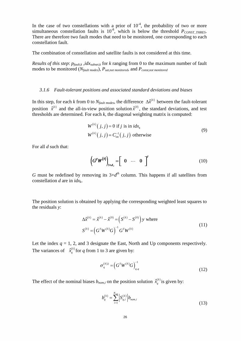
In the case of two constellations with a prior of 10-4, the probability of two or more simultaneous constellation faults is 10-8, which is below the threshold PCONST_THRES. There are therefore two fault modes that need to be monitored, one corresponding to each constellation fault.
The combination of constellation and satellite faults is not considered at this time.
Results of this step: pfault,k ,idxsubset,k for k ranging from 0 to the maximum number of fault modes to be monitored (Nfault modes), Psat,not monitored, and Pconst,not monitored
3.1.6 Fault-tolerant positions and associated standard deviations and biases
In this step, for each k from 0 to Nfault modes, the difference between the fault-tolerant position and the all-in-view position solution ( )0x̂ , the standard deviations, and test thresholds are determined. For each k, the diagonal weighting matrix is computed:
( ) ( )( ) ( ) ( )1
int
, 0 if is in
, , otherwise
kk
k
W j j j idx
W j j C j j−
=
= (9)
For all d such that:
(10)
G must be redefined by removing its 3+dth column. This happens if all satellites from constellation d are in idxk.
The position solution is obtained by applying the corresponding weighted least squares to the residuals y:
(11)
Let the index q = 1, 2, and 3 designate the East, North and Up components respectively. The variances of ( )ˆ k
qx for q from 1 to 3 are given by:
(12)
The effect of the nominal biases bnom,i on the position solution ( )ˆ kqx is given by:
(13)
( )ˆ kx∆( )ˆ kx
( ) ( ) ( ) ( ) ( )( )( ) ( )( ) ( )
0 0
1
ˆ ˆ ˆ wherek k k
k k kT T
x x x S S y
S G W G G W−
∆ = − = −
=
( ) ( )( ) 12
,
k kTq q q
G W Gσ−
=
( ) ( ), ,
1
satNk k
q q i nom ii
b S b=
=∑

27
The variance of the difference, ( )ˆ kqx∆ , between the all-in-view and the fault tolerant
position solutions is computed:
(14)
Results of this step: , , for k from 0 to Nfault modes, and from q from 1, 2, and 3.
3.1.7 Solution separation threshold tests and chi-square test
Solution Separation Test
There are three threshold tests for each fault. The thresholds are indexed by the fault index k and the coordinate q and noted Tk,q. They are defined by:
(15)
where:
_1,1 ,2 4
FA HORfa fa
faults
PK K Q
N−
= =
(16)
_1,3 2
FA VERTfa
faults
PK Q
N−
=
(17)
Q is the left side of the cumulative distribution function of a zero mean unit Gaussian distribution. Protection Levels can be computed only if for all k and q we have:
(18)
If any of the tests fails, exclusion must be attempted (Section 3.1.10).
χ2 statistic and threshold
The chi-square statistic is computed as follows:
(19)
In this equation, 1acc accW C−= . The threshold is given by:
(20)
( ) ( ) ( )( ) ( ) ( )( )2 0 0, ,. ,. ,. ,.
Tk k kss q q q acc q qS S C S Sσ = − −
( )kqσ
( ),
kss qσ ( )k
qb
( ), , ,
kk q fa q ss qT K σ=
( ) ( )0
,,
ˆ ˆ1
kq q
k qk q
x x
Tτ
−= ≤
( )( )12 T T Tacc acc acc accy W W G G W G G W yχ
−= −
( )22 1
3 _ 21constn N FA CHIT P
χχ −
− −= −
28
In the above equation the operator ( ) 12deg .χ − is the inverse of the cdf of a chi-square
distribution with deg degrees of freedom. If , but , the PL cannot be
considered valid and exclusion cannot be attempted. In this case, the chi-square statistic is larger than expected, but none of the solution separation tests have failed, which suggests that the fault is outside the threat model. This test is a sanity check and is not expected to happen.
Results of this step: Thresholds Tk,q, decision on whether to continue with Protection Level calculation, attempt fault exclusion, or declare the VPL invalid.
3.1.8 Protection Levels
Vertical Protection Level (VPL)
The VPL is the solution to the equation:
(21)
The output VPL must be within TOLPL of the solution of this equation. There are several methods available to solve this equation. Annex C proposes one of them, as well as a tight upper bound. The formal proof of safety associated to this Protection Level can be found in [RD-12].
Horizontal Protection Level (HPL)
For the HPL computations, first compute HPLq for q=1 and 2. HPLq is the solution to the equation:
( )
( )
( )
( )
0,
,01
122
fault modes kNq q q k q q
fault k HORkkq q
HPL b HPL T bQ p Q PHMI
σ σ=
− − −+ =
∑ (22)
The output HPLq must be within TOLPL of the solution of this equation. As for the VPL, this equation can be solved using a half interval search. The initial lower and upper bounds are given in Annex C. The HPL is given by:
(23)
22 T
χχ > , 1k qτ ≤
2 21 2HPL HPL HPL= +
29
Results of this step: VPL and HPL
3.1.9 Accuracy, the fault free position error bound, and Effective Monitor Threshold
The standard deviation of the position solution used for these two criteria is given by:
(24)
The formulas for the two accuracy requirements are given by:
(25)
(26)
Because 10 m / Kff is smaller than 4 m / KACC, (26), the latter of these two tests is the only one that needs to be evaluated by the aircraft.
The EMT takes into account the faults with a prior that is equal or larger than PEMT. It is computed as follows:
(27)
(28)
( )( ),
,3 , , ,|maxfaul k EMT
kk md EMT k v EMTk p P
EMT T K σ≥
= + (29)
Results of this step: 95% accuracy, the 10-7 fault free position error bound, and EMT
3.1.10 Fault exclusion (preliminary)
Fault exclusion is performed based on the test results τk,q from Section 3.1.7. Fault exclusion can only be performed if one of these test statistics has exceeded its threshold. We define:
(30)
(31)
( ) ( )0 0, 3,. 3,.
Tv acc accS C Sσ =
( ) _95% ACC v accaccuracy K σ=
( )7,10 FF v accfault free K σ−− =
1, ,
,2EMT
md EMT kfault k
PK Qp
−
=
( ) ( ) ( ), 3,. 3,.k k k T
v EMT accS C Sσ =
{ }min ,min | 1k k qN idx τ= >
{ }min_ _ min ,| , 1failed subsets k k qindex k idx N τ= = >

30
In the above equation, the notation kidx is the number of elements in idxk. Then, among the subsets with the least satellites that have failed, the index kex,cand corresponding to the one that exceeded the threshold with the largest margin is determined:
(32)
The subset kex,cand is a candidate for exclusion. Steps 2, 3, 4, and 5 (described in Sections 3.1.4 to 3.1.7) are performed on the remaining satellites. If the remaining satellites pass the consistency checks in 5,step 5 (in Section 3.1.7), then the excluded satellites are flagged and steps 6, 7, and 8(in Sections 3.1.8 to 3.1.10) can be performed. If not, then the subset with the next largest τk,q and Nmin satellites is tested. The subsets are tested from the smallest to the largest subset size (the subset size is the number of satellites in the subset). Among the subsets of the same size, they are tested from largest τk,q to the smallest. If none of the subsets are found to be consistent, all satellites must be flagged.
Result of this step: Index of faulted satellites or constellations
3.1.11 Monitoring previously excluded satellites (preliminary)
Satellites previously excluded must be monitored every TCHECK. This is done by comparing the measured range to the expected range. The expected range PRexpected is based on the position and clock solution using the healthy satellites. The excluded satellite can only be included in the solution once it has passed a threshold test for the last TRECOV. The threshold test is not yet defined.
Result of this step: consistency of previously excluded satellites (flags)
3.2 List of possible improvements
Possible improvements of the reference algorithm were considered and studied to varying degrees by the ARAIM subgroup. These improvements are briefly described in this sub-section. They can be classified by where they differ from the reference algorithm.
3.2.1 Improvements in the calculation of the Protection Level
,min_ _
maxex cand
failed subsets
k kk index
τ τ∈
=

31
The Protection Level defined in 3.1.8 may be reduced by refining the calculation of the integrity risk. A description of this approach can be found in [RD-13]. In the reference algorithm, the upper bound of the contribution is used:
(33)
In this proposed change, a finer upper bound is defined as a function of two parameters instead of one:
(34)
The function F is defined as:
(35)
The Protection Level is then the solution of the modified equation:
( )
( )
( )
( ) ( )
( )
( ) ( )
0 0,3 33 3
,0 2 0 2 2 0 213 3 3 3 3
, ,
2 ,fault modes kN
kfault k k kk
VERT sat not monitored const not monitored
VPL T bVPL bQ p F
PHMI P P
σσ σ σ σ σ=
− −− + − − = − −
∑ (36)
A similar idea is exploited in the Q-method [RD-14]. In the Q-method, a two dimensional function, or map, is pre-computed. For a given probability of misdetection, this map provides the PL as a function of two parameters related to the geometry.
3.2.2 Threat model modifications
The threat model can be refined by limiting the potential effect of constellation-wide faults [RD-15], [RD-16]. Constellation-wide faults caused by erroneous Earth Orientation Parameters (EOP)/ Earth Orientation Prediction Parameters (EOPPs) would mostly affect the position error in the horizontal plane, and in a consistent way. This constraint can be expressed by writing that a fault mode is the addition of a nuisance parameter bEOP. The measurement model in the faulted case is given by:
(37)
In this equation yi is the vector of measurements from constellation i. The variable x is the actual position and clock offsets. The matrix [G1
T G2T]T is the matrix G defined
above. is defined by:
( )( )
( ),3 3
3
| fault k
kk
VPL T bP HMI k Q
σ
− −≤
( )( )
( ) ( )
( )
( ) ( )
0,3 3 3
2 0 2 2 0 23 3 3 3
| fault ,k
k
k k
VPL T bP HMI k F σ
σ σ σ σ
− − ≤ − −
( ) ( ) ( )2, max 1u
F Q u Q uγ ρ ρ γ ρ= + −

32
(38)
If only the East West coordinate is affected then:
(39)
This modified constellation fault can be handled either with a chi-squared approach as outlined in [RD-15], or within the framework of the reference solution separation algorithm [RD-17], by computing a position solution tolerant to this fault. The algorithm then proceeds identically.
It is possible to relax the constraint that the error only affects the horizontal coordinates by allowing the vertical position error due to the fault to be non-zero, but by bounding its magnitude by the magnitude of the error in the horizontal plane [RD-16].
These approaches are very appealing because they lessen the effect of constellation wide faults on availability, to the point where they barely affect it. However, it is not known to the subgroup at this time whether it can be assumed that the vertical error caused by constellation wide faults is always no larger than the horizontal errors. Additionally, it is not clear that EOP/EOPP faults can only affect one constellation at a time
3.2.3 Ground validated long term ephemeris for EOP fault mitigation
As in the previous section, the objective of this proposed improvement is to mitigate the effect of constellation wide faults. The idea consists of sending to the user a validated source for the computation of satellite position, which can either be used directly in the positioning process or for detection of faults in the current broadcast ephemerides. A method of the second type, which is directly applicable to the detection of EOP/EOPP faults, is described in [RD-18]. The method uses adjacent ephemerides to detect EOP/EOPP faults introduced at ephemeris data set cutovers. It is significant that this method, unlike the ARAIM methods described in the sections above, does not depend on independence of EOP/EOPP faults across GNSS core constellations. The drawback is that EOP/EOPP faults that are solely growing relative to the specified GPS fault exposure limit of 6 hours [RD-19] cannot be reliably detected using adjacent ephemeris tests. An alternative method, based on long-term projection of validated ephemerides is briefly introduced in [RD-20] and is currently being investigated. Related methods have exhibited good performance for long-term orbit propagation in mobile phone positioning applications [RD-21]. The role of the ARAIM ground segment (which determines the ISM) would be to create projection model parameters using a series of previously ground-validated ephemerides.
Using auxiliary methods like these to eliminate EOP/EOPP faults would allow the receiver ARAIM algorithms to assume a very low probability of constellation fault Pconst, and it would alleviate the need to prove independence of EOP/EOPP faults across constellations. Such methods would also be effective in a single constellation reversionary mode.

33
3.2.4 Improvements in the position solution
The reference algorithm computes an all-in-view position solution based on a least squares approach using Cint as the covariance of the pseudorange errors. The Protection Level may be reduced by choosing a different position solution. This approach has been exploited within the framework of slope-based RAIM, where single faults are assumed and accuracy constraints are not considered [RD-22]. It has also been exploited in the case of a simplified threat model where only constellation faults are assumed [RD-23].
It is possible to simultaneously optimize the integrity allocation and the position solution, take into account additional constraints when generating the position solution (for example the accuracy), and do it for any threat model (in particular multiple faults). This is done by casting the problem as a convex optimization problem. The algorithm is described in [RD-24]. To illustrate the algorithm, the Vertical Protection Level equation is rewritten to make the threshold explicit:
( )
( )
( ) ( )( ) ( ) ( )( ) ( )
( )
0 00 ,3 3,. 3,. 3,. 3,. 3
3,0
13 3
, ,
2fault modes
Tk k kNfa acc
fault k kk
VERT sat not monitored const not monitored
VPL K S S C S S bVPL bQ p Q
PHMI P P
σ σ=
− − − − −
+ =
− −
∑ (40)
The approach consists on modifying the all-in-view position solution coefficients so that the VPL is minimized (that is, is no longer calculated using a weighted least-squares) while meeting the accuracy and EMT constraints.
3.2.5 Test simplification
It is possible to bypass the computation of all subsets positions at the expense of a slightly degraded performance, by using the following inequality:
(41)
The only test to be performed is to check whether:
(42)
If the test passes, the Protection Levels are computed taking:
(43)
More details on this simplification can be found in Appendix F of [RD-11].
( )03,.S
( )03,.S
( ) ( ) ( ) ( ) ( )( )( )2 2 10 2,ˆ ˆ ˆk k k T T T
q q q ss q acc acc acc accx x x y W W G G W G G W yσ−
∆ = − ≤ −
( )( ) ( )2
1 2 13,
1const
T T Tacc acc acc acc n N FAalternate
y W W G G W G G W y T Pχ
χ− −
− −− ≤ = −
( )2, , ,
kk q ss q alternate
T Tχ
σ=

34

35
4 PERFORMANCE EVALUATION.
Service volume simulations are one important element in the definition of a future ARAIM architecture. The obtained results allow a prediction of the performance that can be expected under a number of conditions concerning constellation size, characteristics and performances of participating constellations and satellites. Parametric service volume simulations also allow an assessment of the sensitivity of key parameters and their impact on the overall compliance against the LPV-200 requirements that were set as target for a future ARAIM architecture. The performance evaluation against the LPV-200 requirements follows the interpretation given in Sections 2 of this document.
This section provides an overview of a set of service volume simulations and the estimated performance for an ARAIM architecture under a number of assumptions and error models (see section 5).
In addition this section also presents a number of sensitivity analyses in order to assess the implications of key input characteristics on the constellation performance and subsequent compliance with the LPV-200 requirements.
4.1 Scenario Definition
4.1.1 GNSS Constellation Characteristics
Three different constellations are considered for the ARAIM performance analysis. For GPS the nominal constellation with 24 satellites (GPS24) is assessed as well as the expanded 24-slot GPS constellation containing 27 active satellites (GPS27). Both constellations are identified in [RD-01]. For Galileo the nominal constellation consisting of 27 active satellites in a Walker 27/3/1 (Galileo27) formation is considered.
Constellation Characterization Reference
GPS24 24-slot nominal GPS constellation SPS 2008
GPS27 Expanded 24-slot GPS constellation SPS 2008
Galileo27 Walker 27/3/1,56º inclination, SMA 29601.3 km
Table 4-1. Reference core constellations
For both GPS and Galileo a user elevation masking angle of 5 degrees is applied. Two dual constellations configurations were tested: GPS with 24 satellites plus Galileo with 27, and GPS with 27 satellites plus Galileo with 27. To account for some uncertainty in the future constellations, each constellation was degraded by removing one satellite in
The parameters characterizing the performance of both GPS and Galileo dual frequency E1/L1, E5a/L5 services were set in a manner to resemble a possible future performance. However these system characteristics should be taken as indicative and typical values that might not be guaranteed by the core constellations itself and therefore need to be assured by the ARAIM architecture (ground and user segment).

36
each constellation in the first case, and by removing one satellite in the Galileo constellation in the second case. The degraded constellations are described in [RD-25].
4.1.2 User Ranging Characteristics
The pseudorange error accounts for the nominal errors inherent to every ranging source. These errors are caused by the accuracy limits of the ground segment’s orbit and clock determination process, by the modelling limits of the navigation message format (e.g. selected set of orbit and clock parameters), and mainly by the accuracy limits of the on-board clock prediction model. In addition tropospheric error, code noise and multipath are also considered as nominal errors. Reference UERE budgets for both GPS and Galileo are specified in Annex B. For each pseudorange, the error is characterized by a Gaussian distribution and a maximum bias.
4.1.3 Satellite Fault and Constellation Fault Probabilities
Generally both single faults (Psat) and constellation wide faults (Pconst) are considered by the reference algorithm as outlined in section 3. Given the fact that the feared event characterization to be handled within Task 3.2 of the Terms of Reference [RD-01] is still ongoing, only preliminary results are provided in this report – a parametric approach is analysing the sensitivity of the LPV-200 availability with respect to satellite and constellation wide faults. The following range for satellite and constellation faults was considered:
Psat Pconst
1e-3, 1e-4, 1e-5 1e-4, 1e-5, 1e-6
Table 4-2. Range of fault probabilities
4.1.4 Requirements
The applied LPV-200 requirements follow the description in Section 2 and are implemented as described in Section 3. A continuity risk of 4x10⁻⁶ is allocated to the avionics algorithm, and an allowed probability of HMI of 1x10⁻⁷ is assumed. In the simulation, only the VPL, EMT and accuracy are used to assess availability. [RD-02] suggests that that horizontal integrity for LPV-200 can already be assumed using only 2% of the complete budget, while 98% remains in the vertical allocation sub-tree.
4.2 Performance Prediction
This section provides the possible ARAIM performance and its compliance against the LPV-200 target performance level. As already mentioned a parametric analysis approach was selected as this approach will also give further insight on the minimum performance levels that the combination of GNSS core constellation supported by the ARAIM elements (ground and user segment) need to provide. Therefore the Psat and Pconst values identified in the following tables need to be seen as the probabilities of failure for satellite and constellation after augmentation by an ARAIM ground segment. This will provide a clearer insight on the failure probability that the GNSS core system and
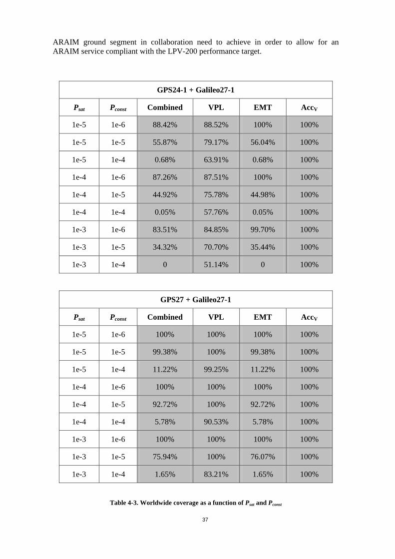
37
ARAIM ground segment in collaboration need to achieve in order to allow for an ARAIM service compliant with the LPV-200 performance target.
GPS24-1 + Galileo27-1
Psat Pconst Combined VPL EMT AccV
1e-5 1e-6 88.42% 88.52% 100% 100%
1e-5 1e-5 55.87% 79.17% 56.04% 100%
1e-5 1e-4 0.68% 63.91% 0.68% 100%
1e-4 1e-6 87.26% 87.51% 100% 100%
1e-4 1e-5 44.92% 75.78% 44.98% 100%
1e-4 1e-4 0.05% 57.76% 0.05% 100%
1e-3 1e-6 83.51% 84.85% 99.70% 100%
1e-3 1e-5 34.32% 70.70% 35.44% 100%
1e-3 1e-4 0 51.14% 0 100%
GPS27 + Galileo27-1
Psat Pconst Combined VPL EMT AccV
1e-5 1e-6 100% 100% 100% 100%
1e-5 1e-5 99.38% 100% 99.38% 100%
1e-5 1e-4 11.22% 99.25% 11.22% 100%
1e-4 1e-6 100% 100% 100% 100%
1e-4 1e-5 92.72% 100% 92.72% 100%
1e-4 1e-4 5.78% 90.53% 5.78% 100%
1e-3 1e-6 100% 100% 100% 100%
1e-3 1e-5 75.94% 100% 76.07% 100%
1e-3 1e-4 1.65% 83.21% 1.65% 100%
Table 4-3. Worldwide coverage as a function of Psat and Pconst
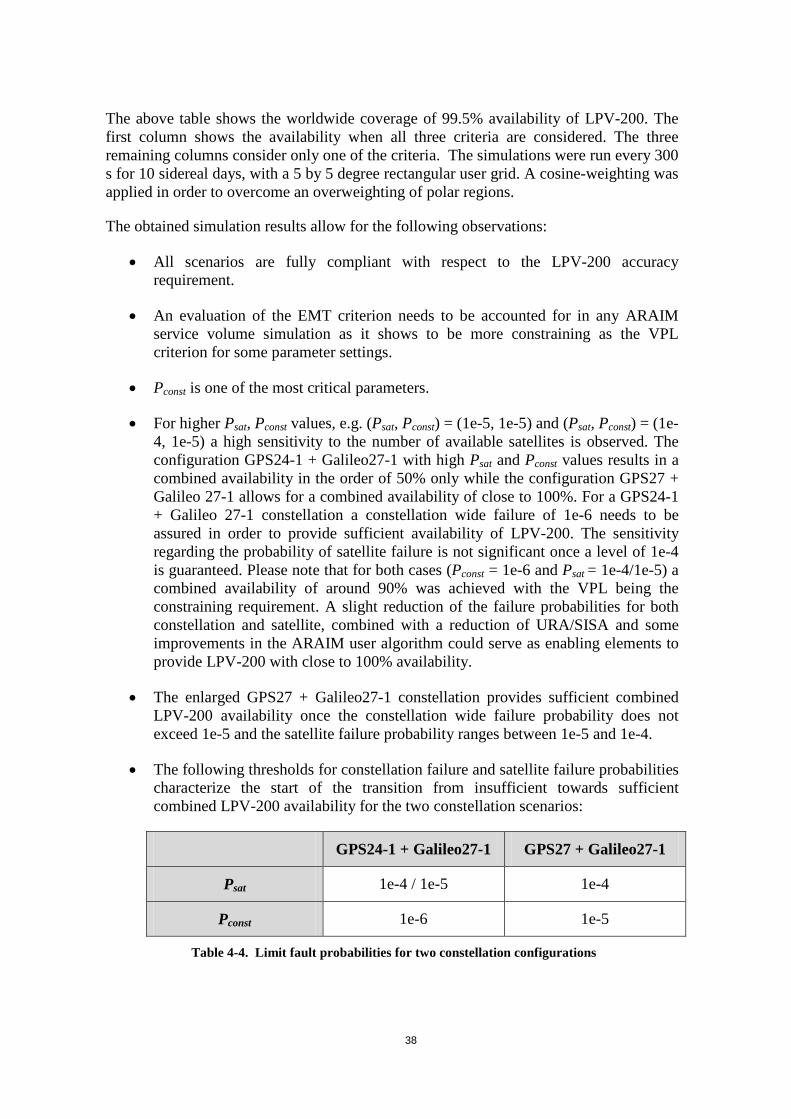
38
The above table shows the worldwide coverage of 99.5% availability of LPV-200. The first column shows the availability when all three criteria are considered. The three remaining columns consider only one of the criteria. The simulations were run every 300 s for 10 sidereal days, with a 5 by 5 degree rectangular user grid. A cosine-weighting was applied in order to overcome an overweighting of polar regions.
The obtained simulation results allow for the following observations:
• All scenarios are fully compliant with respect to the LPV-200 accuracy requirement.
• An evaluation of the EMT criterion needs to be accounted for in any ARAIM service volume simulation as it shows to be more constraining as the VPL criterion for some parameter settings.
• Pconst is one of the most critical parameters.
• For higher Psat, Pconst values, e.g. (Psat, Pconst) = (1e-5, 1e-5) and (Psat, Pconst) = (1e-4, 1e-5) a high sensitivity to the number of available satellites is observed. The configuration GPS24-1 + Galileo27-1 with high Psat and Pconst values results in a combined availability in the order of 50% only while the configuration GPS27 + Galileo 27-1 allows for a combined availability of close to 100%. For a GPS24-1 + Galileo 27-1 constellation a constellation wide failure of 1e-6 needs to be assured in order to provide sufficient availability of LPV-200. The sensitivity regarding the probability of satellite failure is not significant once a level of 1e-4 is guaranteed. Please note that for both cases (Pconst = 1e-6 and Psat = 1e-4/1e-5) a combined availability of around 90% was achieved with the VPL being the constraining requirement. A slight reduction of the failure probabilities for both constellation and satellite, combined with a reduction of URA/SISA and some improvements in the ARAIM user algorithm could serve as enabling elements to provide LPV-200 with close to 100% availability.
• The enlarged GPS27 + Galileo27-1 constellation provides sufficient combined LPV-200 availability once the constellation wide failure probability does not exceed 1e-5 and the satellite failure probability ranges between 1e-5 and 1e-4.
• The following thresholds for constellation failure and satellite failure probabilities characterize the start of the transition from insufficient towards sufficient combined LPV-200 availability for the two constellation scenarios:
GPS24-1 + Galileo27-1 GPS27 + Galileo27-1
Psat 1e-4 / 1e-5 1e-4
Pconst 1e-6 1e-5
Table 4-4. Limit fault probabilities for two constellation configurations

39
4.3 Simulation Tool Crosscheck
Different service volume simulation software tools existed at the ARAIM SG participating entities. Each of these simulation tools was developed independently. In order to establish a common reference for future ARAIM development, evolution and fine-tuning the ARAIM SG agreed to crosscheck and harmonize all these tools such that in the future a thorough level of confidence can be placed on the results generated by the different group members. In addition this exercise deepened the mutual knowledge and understanding in the field of ARAIM and the interpretation of its input parameters and assumptions. Additionally, important aspects regarding the interpretation of the assumptions taken in the GEAS Phase II report [RD-02] were clarified.
The ARAIM service volume simulation tools used in the crosscheck included tools provided by:
• Stanford University (SU) • Illinois Institute of Technology (IIT) • European Space Agency (ESA) • German Aerospace Centre (DLR) • University FAF Munich (UFAF)
4.3.1 Scenario Definition
For crosschecking purposes a specific scenario was defined characterizing all relevant parameters for both GPS and Galileo that can be found in [RD-25]. The scenario definition as given in section 4.1 and Annex B of this document resembles to a large extent the scenario definition used for the crosscheck exercise. However slight deviations were considered, in particular regarding the constellation characterization, in order to check the functional behaviour of the simulation tools.
4.3.2 Crosscheck Results
A step-by-step approach for all five simulation tools involved in the crosscheck ensured a very good level of coherency between the simulation results for all five simulation tools involved in the crosscheck.
The following figures identify the calculated VPL and the relative differences of the calculated VPL for all the simulation tools over a simulation period of 24 hours for one of 3 identified user locations. Comparable results for the VPL over time were obtained for the other two user grid points.

40
Figure 4-1. Absolute VPL for User Location S36.0/E30.0 for 24 hours
Figure 4-2. Relative Difference of VPL for User Location S36.0/E30.0 for 24 hours
As shown in Figure 4-2 the relative differences in the VPL between the different simulation tools are well below 5 cm which was considered sufficient for the simulation tool crosscheck exercise.
Additional simulations covered an entire simulation period of 10 days in order to eliminate longer term drift effects. The obtained absolute VPLs of all simulation tools can be seen in Figure 4-3.
Figure 4-3. Absolute VPL for User Location S36.0/E30.0 for 10 days
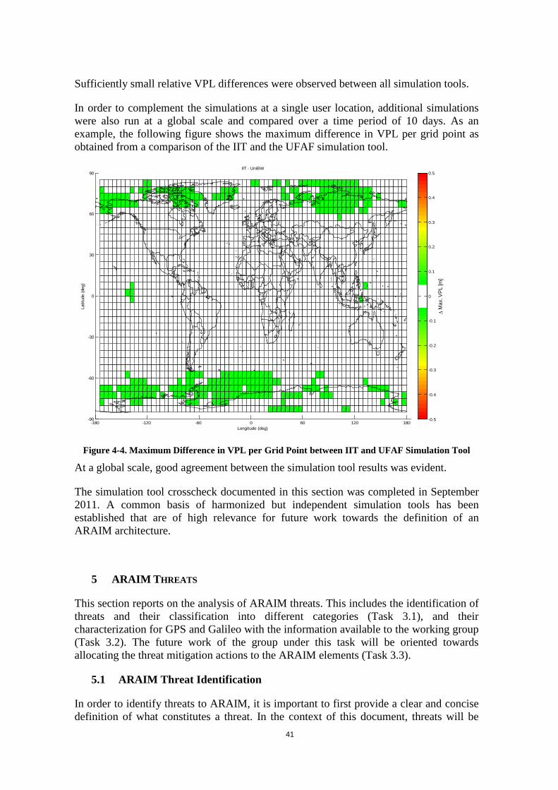
41
Sufficiently small relative VPL differences were observed between all simulation tools.
In order to complement the simulations at a single user location, additional simulations were also run at a global scale and compared over a time period of 10 days. As an example, the following figure shows the maximum difference in VPL per grid point as obtained from a comparison of the IIT and the UFAF simulation tool.
Figure 4-4. Maximum Difference in VPL per Grid Point between IIT and UFAF Simulation Tool
At a global scale, good agreement between the simulation tool results was evident.
The simulation tool crosscheck documented in this section was completed in September 2011. A common basis of harmonized but independent simulation tools has been established that are of high relevance for future work towards the definition of an ARAIM architecture.
5 ARAIM THREATS
This section reports on the analysis of ARAIM threats. This includes the identification of threats and their classification into different categories (Task 3.1), and their characterization for GPS and Galileo with the information available to the working group (Task 3.2). The future work of the group under this task will be oriented towards allocating the threat mitigation actions to the ARAIM elements (Task 3.3).
5.1 ARAIM Threat Identification
In order to identify threats to ARAIM, it is important to first provide a clear and concise definition of what constitutes a threat. In the context of this document, threats will be
-180 -120 -60 0 60 120 180-90
-60
-30
0
30
60
90IIT - UniBW
Longitude (deg)
Latit
ude
(deg
)
∆ M
ax. V
PL [m
]
-0.5
-0.4
-0.3
-0.2
-0.1
0
0.1
0.2
0.3
0.4
0.5

42
defined with the aviation user in mind, but attempting to avoid a loss of generality so that the current framework might accommodate the needs of other navigation users as well.
Navigation threats are considered to be all possible events (i.e. of natural, systemic or operational nature) that can drive the computed navigation solution to deviate from the true position, regardless of whether a specific fault can be identified in one of the navigation systems or not. ARAIM threats are those which can impact the performance of the ARAIM algorithm and whose probability of occurrence is larger than a required integrity risk. Based on the current methods for error modeling, the entire possible threat space can be covered by a nominal error model, plus an uncorrelated fault / residual error per satellite. The remaining correlated and uncharacterized errors can all be grouped into a final “wide fault” term. The set of possible events can be partitioned in the following three categories:
1. nominal errors, i.e. errors under nominal conditions, when all systems (space, ground and user segments) operate normally. These threats are inherent to the system (e.g. receiver noise, multipath, tropospheric delay, inter-frequency bias, nominal signal deformation, code noise, nominal orbit determination and satellite clock errors)). These nominal errors may be overbounded using Gaussian probability distributions (potentially with inflated variances and/or non-zero means).
2. single (narrow) faults, i.e. uncorrelated errors affecting satellites individually and which do not enter into the first category. They can be induced by space or ground segment faults, and affect the navigation signals/message of just one satellite. This type of fault also reflects the situation where small errors induced on the satellite could occur with a greater frequency than errors that would be expected for the corresponding URE/SISE, URA/SISA, and maximum nominal bias terms. The fault origin can be e.g. satellite clock run-offs, code-carrier incoherence, signal deformations, GNSS loss of signal, etc.
3. wide (multiple) faults, i.e. correlated errors induced by space or ground segment faults, that affect navigation signals/messages from multiple satellites and which do not enter into the first two categories. For example, EOP/EOPP faults and other threats that originate from possible software or operator errors at the ground segment that are passed on to users through erroneous data uploads.
Based on definitions above, the following classes of ARAIM threats were identified by the WG-C ARAIM Subgroup:
1) Satellite Clock and Ephemeris 2) Signal Deformation 3) Code-Carrier Incoherence 4) Inter-Frequency Bias (IFB) 5) Satellite Antenna Bias 6) Ionospheric 7) Tropospheric 8) Receiver Noise and Multipath
This classification of the threats by source exhausts all possible segments of the navigation system where these errors could originate. As such, any other fault causes (e.g. user error) are not meant to be covered by the ARAIM integrity guarantee and should be factored appropriately in any fault tree analysis.

43
5.1.1 Satellite Clock and Ephemeris Threats
The nominal satellite clock and ephemeris errors are caused by the accuracy limits of the ground segment orbit and clock determination process, by the modeling limits of the navigation message format (e.g. selected set of orbit and clock parameters), and mainly by the accuracy limits of the on-board clock prediction model, given that the navigation message may not be refreshed by the ground segment for a few hours. Under nominal conditions the Master Control Station (MCS), or the equivalent for each constellation, can accurately compute clock and orbit corrections and correspondingly mitigate this error source. After applying the corrections, the residual errors can be bounded using standard statistical techniques. Information regarding nominal GPS ephemeris and clock nominal errors can be found in [RD-26], [RD-27], [RD-28], [RD-29]. Information regarding Galileo ephemeris and clock foreseen nominal errors can be found in [RD-30]. Clock and ephemeris threats are expected to affect the code and carrier signals on all frequencies equally. However the clock and ephemeris navigation data may differ from one frequency to another.
A system fault, either on the ground or in the satellites, may create jumps, ramps, or higher order errors in the satellite clock, ephemeris, or both [RD-31], [RD-32], [RD-33], [RD-34], [RD-35]. Such faults may be created by changes in state of the satellite orbit or clock, or simply due to the broadcasting of erroneous information. Constellation MCS routinely generate ephemeris and clock corrections and estimate the EOP/EOPPs. The EOPPs are used for a mathematical description of the relationship between the Earth Centered Earth Fixed (ECEF) and International Celestial Reference Frame (ICRF) coordinate systems. As a result, possible externally induced ground segment faults (e. g. wrong EOPP used by MCS and transmitted to the users) would affect all satellites within a given GNSS constellation:
a. Erroneous EOP and EOPP – In principle, if such erroneous EOP and EOPP faults are not detected by the GNSS ground system, the satellite ephemerides could be corrupted in a consistent way, rendering existing ARAIM algorithms ineffective. The initial credibility of the EOP/EOPP threat is established by the fact that it is, for instance, explicitly listed as a potential integrity fault mode in the current GPS Standard Positioning Service Performance Standard [RD-19]. It is distinguished from other postulated consistent faults because it is the only consistent fault specifically identified in GPS SPS-PS. It is possible to separate potential EOP threats into two basic types (analogous to GBAS ephemeris fault types):
1. Type A: EOPPs used in Orbit Determination process are good, but Earth motion has changed since upload (e.g. due to a strong earthquake).
2. Type B: EOPPs used in Orbit Determination process are bad, and the situation is not detected by MCS prior to upload.
These two types of EOP threats can have the same general impact on ephemeris parameters and user positioning errors, but can differ in magnitude and also in what concerns the methods of detection. Type A faults can only be detected by monitoring real-time ground station data, e.g., civil monitoring network, GPS Master Station monitoring, or Galileo GMS. (None of the methods described in Section 3 would be effective against this type of fault.) However, given that EOP updates are used daily or even weekly, any abrupt changes in Earth angular rate would need to be extremely large to accumulate significant orientation errors between EOP update periods. In turn, these rotation changes could only be caused by abrupt changes in the Earth mass distribution, for which only two potential mechanisms are known: geological events

44
and large-scale metrological phenomena. Fortunately, geological events, which include earthquakes or volcanic eruptions, are far too small to cause a measurable impact on Earth rotation2. In contrast, large-scale meteorological phenomena can certainly cause measurable Earth rotation changes, but these develop very slowly over timescales of several months and would be directly accounted for in the EOPs/EOPPs used in constellation orbit determination. Therefore the ARAIM SG has ruled out Type A events and will focus only on Type B from this point forward.
b. Other faults, e.g. displacement of the monitor station antenna phase centers due to earthquakes, intentional/ unintentional interference at the ground monitor stations. Wrong Solar Radiation Pressure (SRP) models can also be considered in this category, if the information comes from an external source.
5.1.2 Signal Deformation Threats
Nominal signal deformation errors are caused by the satellite-to-satellite variability of the small imperfections of the broadcast of pseudo-random ranging signal created by the end-to-end onboard signal generation chain. This chain encompasses the navigation signal generation in the baseband, its up-conversion from baseband to L-band, its amplification, its filtering (e.g. to limit out-of-band emissions), and its feeding to the L-band antenna including its subsequent radiation. The induced tracking errors are user receiver dependent (e.g. on the pre-correlation bandwidth and on the code-loop discriminator). The amount of nominal signal deformation that is situated within the equipment design specs will cause small errors at the user level [RD-36], [RD-37]
Additionally, faulted signal distortions may occur in any or all of the L1/E1 or L5/E5a signals. For the GPS L1 C/A code, the ICAO adopted a threat model in year 2000 to describe the possible faulted signal distortions [RD-06]. These faulted distortions also lead to biases that depend upon the correlator spacing and bandwidth of the observing receivers. Signal deformation may occur independently on any of the code measurements. It does not affect all receivers identically. It is not expected to affect the carrier measurements significantly.
5.1.3 Code-Carrier Incoherence Threats
A satellite may fail to maintain the coherency between the broadcast code and carrier. This fault mode has never been observed on the GPS L1 signals, but has been observed on WAAS geostationary signals and on the GPS L5 signal [RD-38], [RD-39]. This fault mode occurs on the satellite and is unrelated to incoherence caused by the ionosphere. This threat may cause a step or a rate of change between the code and carrier broadcast from the satellite.
2NASA models estimate < 10 µsec change in day length following recent major earthquakes (8.8 - 9.1 mag). This would lead to a user position error growth < 5 mm/day. According to the U.S. Naval Observatory (USNO) earthquake impact on EOPs is so small that it has not thus far been possible to measure. They have never seen any physical evidence of an earthquake affecting the rotation rate of the Earth.

45
5.1.4 IFB Threats
The inter-frequency biases (IFB) are defined as the delay differences relative to the signal paths and the signal modulation type. There is a nominal bias term that will be estimated and broadcast to the user, but there will be a small residual bias remaining. The inter-frequency bias can suddenly change due to an equipment fault on board the GNSS satellite. IFBs are effectively timing differences between one frequency and another. Unlike signal deformation all receivers are affected identically and it only comes into play when comparing one frequency (or frequency combination) to another.
5.1.5 Antenna Bias Threats
Look-angle dependent biases in the code phase and carrier phases on both L1/E1 and L5/E5a are present on GNSS L-band antennas. For the GPS satellites, these biases may be up to several decimeters [RD-40], [RD-41]. These biases will also affect ground reference station antennas and the aircraft antennas. Given that the spacecraft position and attitude relative to a fixed user repeat every sidereal day for GPS spacecraft (excluding long-term drifts) and approximately every 10 days for the Galileo spacecraft, the effect of the antenna biases could be considered as a periodic systematic error for a fixed user. Therefore, there might be some points in the service volume where the biases tend to more consistent across multiple satellites. Although calibration may be applied, the possibility of temporal changes (due to thermal effects or aging) hampers its practicality. Moreover, any correction scheme based on calibration data would require the GNSS spacecraft attitude relative to the user to be determined at the user receiver level. However, this systematic error can be accounted for within the maximum nominal bias term to be broadcast to ARAIM users. These biases depend on the look angle of the signal through the antenna and may be different for each frequency and for code and carrier.
5.1.6 Ionospheric Threats
Signals from low-elevation satellites experience much more refraction on their longer way through the atmosphere in comparison to the signals from high-elevation satellites. The ionosphere is a dispersive medium that leads to code and carrier divergence. The ionospheric error consists of first-, second- and third order effects and the effect of the bending of the signal. These effects are all functions of the Total Electron Content (TEC) along the signal path between the receiver and satellite. In a dual-frequency environment, the first-order ionospheric errors can be removed by measuring the code-carrier divergence at each frequency. In ARAIM the use of the signals in L1 and L5 allows the user receiver to cancel the effect of the first order effect. The residual noise introduced through first order ionospheric error removal as well as the second order effects are modeled and accounted for in the ARAIM algorithm.
During periods of high solar storm activity, especially for boreal and subtropical latitudes, a process known as scintillation affect signals for a short period of time. The ionosphere refractive index can fluctuate on a localized basis from second to second causing cycle slips or losses of lock that may degrade position accuracy. Severe scintillation may even lead to complete loss of the navigation service. For the dual-frequency ionosphere-free combination used by ARAIM, the ionosphere is no longer a significant source of error. The nominal error is negligible and even under severe ionospheric conditions the residual higher order errors would only be a few centimeters.

46
5.1.7 Tropospheric Threats
Tropospheric errors are typically small compared to satellite faults. For SBAS, historical observations were used to formulate a model and analyze deviations from that model [RD-42]. A conservative bound was applied to the distribution of those deviations. The user protects against the direct effect using the specified formulas [RD-06], [RD-10]. As the troposphere is a relatively more homogenous and predictable medium than the ionosphere in the propagation of the L-band radio waves, no specific threats related to the signal propagation in this region are considered, other than the nominal errors in the tropospheric delay estimation. The troposphere affects all frequencies and code and carrier identically. Its magnitude depends strongly on elevation angle and also on local meteorological conditions.
5.1.8 Receiver Noise and Multipath Threats
Multipath can be categorized according to the causing phenomenon as the result of signal diffraction, specular reflection or diffuse reflection. The dynamics of a reflector and receiver affects the characteristics (amplitude, delay in whole cycles, phase delay and angular speed) of the multipath signal and results in time varying or fixed offset multipath signal. The receiver tracking loop follows the composite signal. The offset in the PVT solution between the composite multipath signal tracking and the direct line-of-sight signal tracking forms the resulting multipath error. Different multipath models are available to describe various environments of nominal operation, applicable to aviation (and other) users. In each operational phase, the user will have to employ an appropriate model based on the severity of the environmental effects (e.g. airborne – Airborne Accuracy Designator-A or B (AAD-A / AAD-B), ground movements, rural / suburban / urban settings and etc.). Multipath will have different instantaneous errors on the code and carrier and on the different frequencies. However environments that lead to large multipath on one signal will also create large multipath on the other signals.
5.2 ARAIM Threat Characterization
This section presents the work performed by the ARAIM SG on ARAIM threat characterization through Milestone 1. Based on the ARAIM threat identification exercise described in the previous section, any threat to the ARAIM system can be categorized according to two properties: (a) as a nominal error or fault impacting one or multiple satellites, and (b) according to the nature of the fault. As not all possible combinations correspond to real threats, before starting any quantitative characterization, the categories were qualitatively analyzed so that those not representing any real threat are removed (appearing as N/A in the table below).

47
Nominal Narrow fault Wide fault
1-Clock and Ephemeris Orbit/clock estimation and prediction and broadcast limits
Includes clock runoffs, bad ephemeris, unflagged manoeuvres
Erroneous EOPP, inadequate manned ops, ground-inherent failures
2-Signal Deformation Nominal differences in signals due to RF components, filters, and antennas waveform distortion
Failures in satellite payload signal generation components. Faulted signal model as described in ICAO
N/A
3-Code-Carrier Incoherence e.g. incoherence observed in IIF L5 signal or GEO L1 signals
e.g. incoherence observed in IIF L5 signal or GEO L1 signals TBC
N/A
4-IFB Delay differences in satellite payload signal paths
Delay differences in satellite payload signal paths TBC
N/A
5-Satellite Antenna Bias Look-angle dependent biases caused at satellite antennas
Look-angle dependent biases caused at satellite antennas TBC
N/A
6-Ionospheric N/A Scintillation Multiple scintillations at solar storms in certain latitudes
7-Tropospheric Nominal troposphere error (after applying SBAS MOPS model for tropo correction)
N/A N/A
8-Receiver Noise and Multipath
Nominal noise and multipath terms in airborne model (TBC Gailleo BOC(1,1) and L5/E5a))
e.g.: receiver tracking failure or multipath from onboard reflector. TBC
e.g.: receiver tracking multiple failure or multipath from onboard reflector. TBC
Table 5-1 - ARAIM Threat Identification Summary
The intent of Task 3.2 is to characterize the identified threats (at least preliminarily at Milestone 1), including its magnitude, duration and likelihood, for GPS and Galileo. The intent of the ARAIM SG participants is however to develop a framework that can be extended to other GNSS as well.
The threats are characterized in the context of GNSS, signal propagation and receiver errors/faults, i.e. threats before the ARAIM system is put into place. In the next step (Task 3.3, "ARAIM Threat Allocation and Mitigation Identification"), the identified threats will be allocated to the ARAIM system blocks (ground, air and potentially GNSS), further defining the ARAIM ground architecture.
It should be noted that, at this stage, there are some intrinsic limitations to the threat characterization process (and, more generally, to the ARAIM SG):
- Galileo deployment is starting and its actual performance has not yet been extensively measured and characterized.
- The threat characterization exercise for GPS is based on performance observation and existing commitments and does not incorporate at this stage information relative to future GPS generations (e.g. GPS III) that could be more reliable and provide improved performance.
- Although some relevant information about the GNSS design and operations has been made available to the group (e.g. concerning EOPP treatment by GPS Ops Squadron), not all GPS and Galileo design and operations information that could

48
be relevant for the threat characterization may have been used, either because it is not publically available or because it is under definition.
In spite of the potential limitations, this threat identification and characterization work supports several objectives that are relevant for the ARAIM SG:
- To provide a global framework in which all possible threats can be systematically traced, to which other constellations can adhere, and which can incorporate more detailed information about Galileo or GPS in the future.
- To identify any potential ARAIM weaknesses or risky areas to be further researched or clarified from constellation service providers.
- To present suggestions to GNSS service providers on the incorporation of mitigation actions at GNSS level or the performance levels required for ARAIM.
- To characterize more realistically input parameter values to the ARAIM algorithm from different constellations (Psat, Pconst, URA/SISA, URE/SISE, bias)
- To provide inputs to the following "threat allocation and mitigation" phase, and the later definition of ARAIM elements.
- To anticipate potential issues towards a future certification of ARAIM for safety applications.
Each threat item in the table refers a single combination of two threat properties mentioned (nominal/narrow/wide and nature) and GNSS (GPS or Galileo). For example, NOM1GPS refers to Nominal errors from clock and ephemeris (1) for GPS, and so on.
Apart from 'GPS' and 'GAL', few threat items are identified as 'ALL' (e.g. WF1ALL). These relate to cross-constellation faults, that is, faults potentially leading to simultaneous errors from both constellations (as e.g. wrong EOPP input parameters), which are of significant relevance for ARAIM as explained throughout the report.
It should be noted that some threats appearing as a single category may result from different causal factors, as e.g. clock runoffs, incorrect operations, unflagged maneuvers, in threat item NF1GAL. In this case, the threat characterization is supposed to account for the aggregate effect of all causes included in the threat item. Further details are provided separately as required.
For readability purposes, the threat characterization table has been moved to Annex H.
6 PROGNOSIS FOR ARAIM
The outlook for ARAIM is favourable, but not yet decisive.
The technical goals for multi-constellation air navigation remain feasible under ARAIM. Specifically, since the life cycle of avionics is twenty years or more, air navigation should not have a brittle dependence on the strength of any individual constellation (i.e. the number of satellites on orbit), nor be overly sensitive to the failure rates of any constellation. For example, new constellations can have dramatically higher failure rates than a mature constellation. Finally, airborne mitigations for radio frequency interference

49
(RFI) may include antennas that attenuate signals from low elevation angles. These antennas effectively raise the mask angle, and multi-constellation navigation compensates for the loss of low-lying satellites. ARAIM is not yet sharply defined, but the ARAIM variants all support the technical goals listed above.
The institutional goals for multi-constellation air navigation also remain feasible under ARAIM. Several GNSS providers may offer their constellations for use by aviators. While technically welcome, these offers must be subject to certain requirements. The GNSS providers in combination with the ARAIM ground segment operator must periodically communicate data needed to support an airborne determination of integrity (error bounding). In addition, nation-states may wish to use a variety of radio systems to broadcast this integrity-critical data to aircraft in their airspace. The broadcast systems will be selected by the ARAIM providers considering re-use of existing radio systems and the potential to enhance the market acceptance of the ARAIM architecture. ARAIM has begun to articulate the rules for GNSS participation in aviation, and the ARAIM architectures continue to afford flexibility with respect to broadcast systems.
Recent progress on the work program has been encouraging. Specifically, progress on the ARAIM airborne integrity processing has provided a widely accepted reference algorithm. In addition, the performance of this algorithm in terms of worldwide coverage with 99.5% availability under specific performance expectations for the contributing GNSS constellations possibly supported by an ARAIM ground segment has been analyzed and found to be favorable with respect to the goal of worldwide LPV-200. Moreover, techniques for treating constellation wide failures introduced by faulty Earth orientation parameters have been presented. This latter issue had troubled ARAIM workers for more than two years, and resolution seems close at hand.
However appreciable work remains. The work includes: identify the level of trust that can be placed in the core GNSS constellations for aviation allowing for future certification of the resulting integrity service; define the monitoring infrastructure and processing; specify the content and tolerable latency for the integrity data from the ground to the air; authoritatively characterize the feared events relevant to ARAIM; and provide a final allocation of the feared events to the various ARAIM and GNSS elements. All of these challenges can be resolved technically, but the cost of the mitigations cannot be reasonably estimated at this time. Therefore, the prospect of ARAIM should not influence current efforts to add an L5 capability to WAAS, nor should it slow efforts to add GPS L5 and Galileo capabilities to EGNOS V3.

50
7 NEXT STEPS
This section provides a path for completing this work based on the ARAIM characteristics described in "Characterizations of ARAIM Architectures" by T. Walter, 2012. This paper (provided as Annex D to this report) identifies the six architecture characteristics summarized in Table 7.1 below.
Ground Monitoring Network. The density of the ground system needed to support ARAIM can vary from sparse to dense. It can also span the globe or be confined to single sites. This reference network may be purpose built for ARAIM or drawn from existing SBAS or GNSS networks.
Single Site Sparse Regional Dense Regional Sparse Global Dense Global
Bounding Methodology. The bounding methodology is categorized by the amount of time that the monitors collect data before updating their estimates of the GNSS constellation health. The ground monitors may be allowed to collect data for one or more days before updating its estimates. On the other hand, the ground network may be responsible for much more rapid bounding of these parameters.
Off-Line (e.g. daily) Rapid Bounding (e.g. minutes)
Assertions Regarding Constellation Faults (i.e. wide faults). The wide faults may be associated with a variety of assertions. These assertions range from: wide faults do not exist to wide faults can simultaneously effect more than one constellation.
None Slow, Independent, and/or One or Two Dimensional
Fast, Independent, and Three Dimensional
Common Across All Constellations
Content of the Integrity Support Messages (ISM). If present, the ISM may need only one bit per satellite to indicate whether that satellite is suitable for use. At the other extreme, it may broadcast a full set of replacement parameters for the ephemeris of every useable satellite.
One Health Bit per Satellite
One Health Bit per Satellite, Other Parameters per
Constellation
Parameters per Satellite, & Pconst per Constellation
All Parameters Plus Ephemeris per
Satellite
Concept of ISM Operation. The ISM may be broadcast continuously to the fleet (e.g. broadcast from SBAS or GNSS). Near the other extreme, it may only reach the aircraft at the time of dispatch.
At Dispatch At Arrival Intermittently Enroute Continuously
Time Between Integrity Support Messages (i.e. Time to ISM Alert, TIA). The TIA measures the end-to-end delay from the onset of an integrity fault to the alert in the aircraft. As such, it is strongly connected to the bounding methodology and the concept of ISM operation.
Months Days Hours Minutes
Table 7-1. Summary of ARAIM Architectural Characteristics
Table 7-1 spans the broad set of ARAIM alternatives that were discussed by the working group. Unfortunately, this table also constitutes a nearly unmanageably large set of alternatives. To provide a manageable path, the ARAIM SG now posits three ARAIM representatives that are based on the time-for-ISM-alert (TIA). The ARAIM SG keyed on TIA, because it is directly connected to the constellation-wide failures that have proven to be the most nettlesome aspect of ARAIM development. Thus, these ARAIM “representatives” will allow us to more deeply understand our sensitivity to constellation-wide threats, and illuminate the best way forward. This set of ARAIM representatives can be augmented or modified as facts reveal themselves.
7.1 The next section describes the ARAIM representatives. ARAIM Representatives
As mentioned above, five tasks are to be completed during the next phase. Three ARAIM Representatives are now posited to focus this work. These will be refined and/or additional representatives may be added during the investigation. The present

51
representatives are described by their nominal update time for the integrity support message (ISM). This key variable is called the time-for-ISM alert or TIA. Classification based on TIA is not immediately sensible or intuitive. However, it enables the SG to explore and treat our main source of uncertainty: constellation-wide faults (also known as wide faults). Moreover, this key characteristic from the table above strongly influences our choice for the other characteristics. Thus, it efficiently decreases the size of our rather unmanageable trade space.
Rapid Time-to-Alert: This first representative (or ARAIM class) is based on rapid bounding and an ISM delivery mechanism that is continuous or nearly continuous. Relative to the alternatives described below, it guarantees a short latency for the Integrity Support Message (TIA measured in minutes). This short TIA class assumes that constellation-wide faults are detected rapidly on the ground and communicated to the aircraft before any appreciable navigation risk accumulates. One may write:
Pr(NSE > PL for precision approach) = TIA ×Rwide
TIA= latency of the Integrity Support Message
NSE = navigation system error
PL = protection level
Rwide = constellation fault rate
In this case, 10-7/hr < Rwide < 10-6/hr, because we target 1 hour > TIA > 0.1 hour for this ARAIM class.
This short TIA representative is reasonably robust to the details of the constellation-wide fault, because we could change the ground algorithms to handle wide faults with new characteristics. In addition, alternatives within this class assume that the ARAIM ground segment can communicate with the airborne fleet after dispatch. Thus, this class is naturally aligned with ISM broadcast by SBAS, GNSS or future ground-to-air data links that have continuous connectivity to the aircraft. These alignments are depicted in the table below.

52
Ground Monitoring Network Single Site Sparse Regional Dense Regional Sparse Global Dense Global
Bounding Methodology
Off-Line (e.g. daily) Rapid Bounding (e.g. minutes)
Assertions Regarding Constellation Faults (i.e. wide faults) None Slow, Independent, and/or
One or Two Dimensional Fast, Independent, and
Three Dimensional Common Across All
Constellations
Content of the ISM One Health Bit per
Satellite One Health Bit per Satellite,
Other Parameters per Constellation
Parameters per Satellite, & Pconst per Constellation
All Parameters Plus Ephemeris per
Satellite
Concept of ISM Operation At Dispatch At Arrival Intermittently Enroute Continuously
Time to ISM Alert (TIA) Months Days Hours Minutes
Table 7-2. Rapid TIA
Offline Determination (long TIA): This representative is based on offline monitoring of the constellations and is compatible with ISM broadcast channels that may reach the aircraft only at dispatch. More specifically, TIA = 1 day or longer. It does not need a real-time or continuous data broadcast. Thus this ARAIM representative admits a greater number of communication alternatives than the short TIA class.
However, the class based on offline monitoring must make at least one of the following assertions regarding constellation-wide faults:
• The a priori probability of constellation-wide faults is low compared to 10-7. • Two or more GNSS constellations are available to support a constellation-to-
constellation test in the aircraft and the faults are independent from one constellation to another.
• The effect of the constellation-wide fault is to move the position fix in no more than one (e.g. longitudinally) or two dimensions (e.g. laterally). In this case, ARAIM only needs to protect against this limited set of fault effects. For example, a fault in the UTC offset in the Earth orientation parameters introduces a longitudinal fault. The a priori probability of constellation-wide faults that introduce three or four dimensions of error is below 10-7.
• The ground can provide enough information to mitigate constellation-wide faults that occur during the flight. For example, consider constellation-wide faults that disturb the ephemeris information contained in the navigation message. For mitigation, the ground system could derive independent ephemerides based on a worldwide monitoring system and central processing system. The monitoring system could be an aggregation of SBAS reference stations, or it could be based on independent receivers sited at GNSS ground stations. The monitoring system would send GNSS measurements to a central hub that would estimate ephemerides with a validity of 24 hours. These substitute ephemerides would be able to support the protection levels needed for vertical guidance worldwide. The ground system would communicate these ephemerides to the aircraft upon

53
dispatch. The aircraft could compare the substitute ephemerides to the data broadcast from the GNSS satellites. Alternatively, the aircraft could navigate based on the substitute ephemerides.
These likely characteristics for offline determination are shown in Annex D.
Ground Monitoring Network Single Site Sparse Regional Dense Regional Sparse Global Dense Global
Bounding Methodology
Off-Line (e.g. daily) Rapid Bounding (e.g. minutes)
Assertions Regarding Constellation Faults (i.e. wide faults) None Slow, Independent, and/or
One or Two Dimensional Fast, Independent, and
Three Dimensional Common Across All
Constellations
Content of the ISM One Health Bit per
Satellite One Health Bit per Satellite,
Other Parameters per Constellation
Parameters per Satellite, & Pconst per Constellation
All Parameters Plus Ephemeris per
Satellite
Concept of ISM Operation At Dispatch At Arrival Intermittently Enroute Continuously
Time to ISM Alert (TIA) Months Days Hours Minutes
Table 7-3. Offline Bounding
Near Real-Time Determination for Arrival (short TIA for arrival): This final example representative augments ARAIM for the arrival procedure. The aircraft may use solutions from either of the above-described classes for enroute and terminal area flight, if necessary. However, in this option, the aircraft must receive a local ISM, in principle from the sovereign air traffic control system, prior to airport approach and landing. This class assumes that constellation-wide faults are detected in near real-time on the ground and communicated to the aircraft before any appreciable arrival risk accumulates. One may write:
Pr(NSE > PL for enroute flight) = TIAenroute×Rwide
Pr(NSE > PL for arrival) = TIAarrival×Rwide
TIAenroute= ISM latency supported during enroute flight
TIAarrival = ISM latency supported during arrival flight
NSE = navigation system error
PL = protection level
Rwide = constellation fault rate
In this case, the Rwide can be quite large. After all, the enroute faults must cause errors that are greater than the enroute protection levels. In addition, the arrival faults are mitigated by the small TIAarrival provided by the local data link.

54
This class is naturally aligned with ISM broadcast by VDB or other line-of-sight broadcast systems that operate near airports (although a near-real time satellite link could also be envisaged). It would also be well aligned with a sovereign wish for control of the overhead airspace. These alignments are depicted in Annex D.
Ground Monitoring Network Single Site Sparse Regional Dense Regional Sparse Global Dense Global
Bounding Methodology
Off-Line (e.g. daily) Rapid Bounding (e.g. minutes)
Assertions Regarding Constellation Faults (i.e. wide faults). None Slow, Independent, and/or
One or Two Dimensional Fast, Independent, and
Three Dimensional Common Across All
Constellations
Content of the Integrity Support Messages (ISM) One Health Bit per
Satellite One Health Bit per Satellite,
Other Parameters per Constellation
Parameters per Satellite, & Pconst per Constellation
All Parameters Plus Ephemeris per
Satellite
Concept of ISM Operation At Dispatch for
Departing & Enroute Aircraft
At Arrival for Arriving Aircraft
Intermittently Enroute Continuously
TIA for Departing & Enroute Aircraft Months Days Hours Minutes
TIA for Arriving Aircraft
Months Days Hours Minutes
Table 7-4. Rapid TIA for Arriving Aircraft
7.2 Next Tasks
Task 2. Performance Evaluation: Define input for ARAIM and a list of all parameters and assumptions necessary to evaluate ARAIM performance against all fault-free and faulted conditions. Agree on common procedure and parameters for performance evaluation and analyse the performance of the proposed ARAIM concept.
Prior to June 2012, Task 2 crosschecked the ARAIM tools built by the different research teams. These crosschecks were based on: single satellite faults; the earliest form of ARAIM; and an equal allocation of integrity across the satellites.
In order to complete Task 2, the working group shall focus on the performance of the ARAIM representatives. The Working Group shall conduct an end-to-end evaluation inclusive of the reference ARAIM algorithm and the ISM message associated with each of the ARAIM representatives described above. If warranted, the Working Group shall use actual GPS and GLONASS measurements to validate the various designs. The results shall be evaluated in the user position domain. The SG shall evaluate integrity risk and availability for one architecture from each of the above-described ARAIM classes and lay down guidelines for evaluating additional architecture classes, should they be considered in the future.

55
As part of this effort, the SG shall ensure that the characterization of airborne multipath is mature. Airborne multipath is important, because dual frequency estimators multiply the L1/E1 and L5/E5 errors. The SG shall also better characterize the impact of satellites that are lost due to scintillation or banking. These loss mechanisms compound multipath, because the multipath error curve must be reset to account for post-loss transient response. Thus integrity needs to be maintained even when one or two of the satellites in view are not being tracked and cannot be used.
Task 3.3. ARAIM Threat Allocation and Mitigation Identification: Allocate the identified threats to the different ARAIM system elements (GNSS space segment, GNSS ground segment, user segment, ARAIM ground segment) and identify corresponding threat mitigations commiserate with the safety risk.
This allocation shall be conducted for the ARAIM representatives. In all cases, the airborne algorithm will include subset treatment based on the threats and associated probabilities. For example, the satellite fault probability (Psat) would determine the size of the excluded satellite sets. The constellation-wide fault probability (Pconst) would determine the mitigation strategy for faults in the Earth orientation parameters (EOP) for the three ARAIM representatives.
Task 4. ISM Generation, Design and Dissemination: Analyze the need for additional information required by the ARAIM algorithm to achieve its target specifications for vertical guidance. In case additional information is necessary, the group shall propose, study and recommend the requirements, the generation, the design and possible dissemination of an Integrity Support Message (ISM) to provide any such external information deemed necessary for the ARAIM algorithm to achieve its design requirements.
An ISM data format shall be designed for each of the ARAIM representatives. In each case, one or two likely broadcast channels shall be identified for the ISM design. For example, SBAS (new L5 standard) and suitable GNSS data channels (e.g. L5/E5a or L1C/E1OS) are reasonably associated with the rapid TISM class, because the connectivity is continuous. The long TISM class is very flexible with respect to broadcast channel, and so greater bandwidth could well be available. The rapid bounding representative is reasonably associated with VHF Data Broadcast (VDB) and L-band Digital Aeronautical Communication System (LDACS).
For all examples, ISM bandwidth shall be approximated. ISM bandwidth is a strong function of whether the Psat and URAs are satellite-specific or regarded as constants across the available constellations. ISM bandwidth is also a very strong function of the need to send the satellite ephemeris data that may be needed for the long TISM architecture. Thus ISM bandwidth shall be a function of ARAIM class.
Task 5. Ground Monitoring: Propose, study and recommend ground monitoring approaches for each constellation service performance. Make use of measurement data to characterize the performance of each constellation. Define requirements and candidate methods for the establishment of ISM content, including specifications for civil monitoring of service performance and any necessary assurances to be provided by GNSS core constellation service providers. Ways and benefits of international monitoring data exchange shall be assessed as well.

56
As shown in Annex D, ground monitoring has a weak relationship to the ARAIM SG’s three ARAIM representatives. The ground network collects the raw data from the core GNSS constellations. As shown in the tables, the alternatives are varied from single site monitoring to dense global coverage. For each of the ARAIM representatives, the SG shall propose the most likely reference network properties potentially including: the number of stations, the geographical spread of the network, and the level of redundancy and reliability at each station. The SG can also consider the operation and maintenance aspects of the network, and whether the ground networks are ARAIM dedicated, or shared with other systems.
Task 6. Relationship ARAIM/SBAS: Carefully consider the relationship between ARAIM and Satellite Based Augmentation Systems (SBAS). Both ARAIM and SBAS seem to target the same level of performance (LPV-200), so clarify the operational, technical and other advantages that ARAIM may offer. In addition, define potential SBAS interface with ARAIM necessary to maximize its benefits and if necessary, identify aspects requiring further consolidation and define tasks addressing them, also considering test campaigns if necessary.
ARAIM has two important advantages relative to SBAS. First, it enables the use of all GNSS constellations that provide a reliable and proven ISM. As such, it establishes the rules for the incorporation of new constellations, and provides a path to the availability benefits of multi-constellation navigation for aviation. Second, it does not need every sovereign State to have access to a geostationary satellite. The first and third ARAIM classes are based on a rapid bounding strategy that would be provided by the responsible state, although sovereignty issues of ARAIM require a closer look that will also be part of the SGs subsequent work.
Under Task 6, the Technical Subgroup shall determine whether the promise of ARAIM relative to SBAS has survived the design process with its attendant complications to address new integrity threats.

57
ANNEX A: LIST OF REFERENCES
[RD-01] Terms of Reference of the WG-C ARAIM subgroup
[RD-02] Phase II of the GNSS Evolutionary Architecture Study, February 2010
http://www.faa.gov/about/office_org/headquarters_offices/ato/service_units/techops/navservices/gnss/library/documents/media/GEASPhaseII_Final.pdf
[RD-03] Blanch et al., “A Proposal for Multi-Constellation Advanced RAIM for Vertical Guidance”, submitted to the ION Navigation Journal, December 2011
[RD-04] Blanch, J., Ene, A., Walter, T., Enge, P. “An Optimized Multiple Solution Separation RAIM Algorithm for Vertical Guidance”. Proceedings of the ION GNSS 2007, Fort Worth, TX, September 2007.
[RD-05] Lee, Y. and McLaughlin, M. P., “Feasibility Analysis of RAIM to Provide LPV 200 Approaches with Future GPS,” in Proceedings of ION GNSS-2007, Fort Worth, TX, September 2007.
[RD-06] ICAO, Annex 10, Aeronautical Telecommunications, Volume 1 (Radio Navigation Aids), Amendment 86, effective 17 November 2011. GNSS standards and recommended practices (SARPs) are contained in Section 3.7 and subsections, Appendix B, and Attachment D.
[RD-07] Blanch, J. and Walter, T., “LPV-200 Requirements Interpretation,” Report to ARAIM subgroup, version 4, November, 2011.
[RD-08] Blanch, J., Walter, T., Enge, P. “RAIM with Optimal Integrity and Continuity Allocations Under Multiple failures” IEEE Transactions on Aerospace and Electronic Systems, Vol. 46, No. 3, July 2010.
[RD-09] Ene, A., “Utilization of Modernized Global Navigation Satellite Systems for Aircraft-Based Navigation Integrity,” Doctoral Research Dissertation, VDM VerlagDr. Müller, June 2009.
[RD-10] WAAS Minimum Operational Performance Specification (MOPS), RTCA document DO-229D

58
[RD-11] Blanch, J. “Solution Separation ARAIM Algorithm Description”, white paper, May 2012.
[RD-12] Blanch, J. “Solution Separation ARAIM algorithm: proof of safety for the one-sided cumulative distribution”, white paper, March 2012.
[RD-13] Blanch, J. “ Potential ARAIM Improvements”, Briefing presented at the EU-U.S. Cooperative WG-C ARAIM Subgroup Meeting in Munich, January 2012.
[RD-14] Amarillo, F. “MHSS RAIM with Q transformation” Briefing presented at the EU-US Cooperative WG-C ARAIM Subgroup Meeting in Munich, January 2012.
[RD-15] Lee, Y., “RAIM Using Two Constellations to Provide Integrity for LPV-200 In the Presence of an EOP Fault,” Briefing Presented at the EU-US Cooperative WG-C ARAIM Subgroup Meeting, Stanford University, California, June 20, 2011
[RD-16] Lee, Y., "New Advanced ARAIM with Improved Availability for Detecting Constellation-wide Faults, Using two Independent Constellations," Proceedings of the 2012 International Technical Meeting of The Institute of Navigation, Newport Beach, CA, January 2012, pp. 1708-.
[RD-17] Blanch, J., “MHSS ARAIM Algorithm and Constrained Constellation Faults,” Briefing Presented at the EU-US Cooperative WG-C ARAIM Subgroup Meeting, Portland, September 2011.
[RD-18] B. Pervan, S. Langel, J. Meno, M. Joerger, and F.-C. Chan, “Maturation of EOP Threat Model,” Briefing presented at the WG-C ARAIM SG meeting in Munich, January 18, 2012
[RD-19] Global Positioning System Standard Position Service Performance Standard, , 4th Edition, September 2008
59
[RD-20] B. Pervan, “Maturation of EOP Threat Model,” Briefing presented at the WG-C ARAIM SG teleconference, March 20, 2012
[RD-21] Garrison and Eichel, “An Extended Propagation Ephemeris for GNSS,” NAVIGATION, Vol. 53, No. 3, Fall 2006.
[RD-22] Hwang, P., Brown, R. G., "RAIM FDE Revisited: A New Breakthrough In Availability Performance With NIORAIM (Novel Integrity-Optimized RAIM)," Proceedings of the 2005 National Technical Meeting of The Institute of Navigation, San Diego, CA, January 2005, pp. 654-665.
[RD-23] Lee, Y., "Two New RAIM Methods Based on the Optimally Weighted Average Solution (OWAS) Concept", NAVIGATION, Vol. 54, No. 4, Winter 2007-2008, pp. 333-345.
[RD-24] Blanch, J., Walter, T., Enge, P., "Optimal Positioning for Advanced RAIM," Proceedings of the 2012 International Technical Meeting of The Institute of Navigation, Newport Beach, CA, January 2012, pp. 1624-0.
[RD-25] EU/U.S. ARAIM Subgroup, Scenario Definition for Simulation Tool Crosscheck, Issue 1.4d, July 28, 2011
[RD-26] Jefferson, D. C. and Bar-Sever, Y. E., “Accuracy and Consistency of GPS Broadcast Ephemeris Data,” in Proceedings of ION GPS-2000, Salt Lake City, UT, September 2000.
[RD-27] Warren, D. L. M. and Raquet, J. F., “Broadcast vs. Precise GPS Ephemerides: A Historical Perspective,” Proceedings of the 2002 National Technical Meeting of The Institute of Navigation, San Diego, CA, January 2002, pp. 733-741.
[RD-28] Creel, T., Dorsey, A. J., Mendicki, P. J., Little, J., Mach, R. G., Renfro, B. A., “Summary of Accuracy Improvements from the GPS Legacy Accuracy Improvement Initiative (L-AII),” Proceedings of the 20th International Technical Meeting of the Satellite Division of The Institute of Navigation (ION GNSS 2007), Fort Worth, TX, September 2007, pp. 2481-2498.
60
[RD-29] Heng, L., Gao, G. X., Walter, T., Enge, P., “Statistical Characterization of GPS Signal-In-Space Errors,” Proceedings of the 2011 International Technical Meeting of The Institute of Navigation, San Diego, CA, January 2011, pp. 312-319.
[RD-30] Amarillo-Fernandez, F., Crisci, M., Ballereau, A., John Dow, J., Hollreiser, M., Hahn, J., Gerner, J.L., “The Galileo Ground Mission Segment Performances” International GNSS Service Workshop IGS 2008, Miami, USA
[RD-31] Hansen, A., Walter, T., Lawrence, D., and Enge, P., “GPS Satellite Clock Event of SV#27 and Its Impact on Augmented Navigation Systems,” in Proceedings of ION GPS-98, Nashville, TN, September 1998.
[RD-32] Shank, C. M. and Lavrakas, J. “GPS Integrity: An MCS Perspective,” in Proceeding of ION GPS-1993, Salt Lake City, UT, September 1993.
[RD-33] Rivers, M. H., “2 SOPS Anomaly Resolution on an Aging Constellation,” Proceedings of the 13th International Technical Meeting of the Satellite Division of The Institute of Navigation (ION GPS 2000), Salt Lake City, UT, September 2000, pp. 2547-2550.
[RD-34] Gratton, L., Pramanik, R., Tang, H., Pervan, B., “Ephemeris Failure Rate Analysis and its Impact on Category I LAAS Integrity,” Proceedings of the 20th International Technical Meeting of the Satellite Division of The Institute of Navigation (ION GNSS 2007), Fort Worth, TX, September 2007, pp. 386-394.
[RD-35] Heng, L., Gao, G. X., Walter, T., Enge, P., “GPS Signal-in-Space Anomalies in the Last Decade: Data Mining of 400,000,000 GPS Navigation Messages,” Proceedings of the 23rd International Technical Meeting of The Satellite Division of the Institute of Navigation (ION GNSS 2010), Portland, OR, September 2010, pp. 3115-3122.
[RD-36] Wong, G., Phelts, R.E., Walter, T., Enge, P., “Alternative Characterization of Analog Signal Deformation for GNSS-GPS Satellites,” Proceedings of the 2011 International Technical Meeting of The Institute of Navigation, San Diego, CA, January 2011, pp. 497-507.

61
[RD-37] Wong, G., Phelts, R. E., Walter, T., Enge, P., “Bounding Errors Caused by Nominal GNSS Signal Deformations,” Proceedings of the 24th International Technical Meeting of The Satellite Division of the Institute of Navigation (ION GNSS 2011), Portland, OR, September 2011.
[RD-38] Gordon, S., Sherrell, C., Potter, B.J., “WAAS Offline Monitoring,” Proceedings of the 23rd International Technical Meeting of The Satellite Division of the Institute of Navigation (ION GNSS 2010), Portland, OR, September 2010, pp. 2021-2030.
[RD-39] Montenbruck, O., Hauschild, A., Steigenberger, P., and Langley, R. B., “Three’s the Challenge,” GPS World, July, 2010.
[RD-40] Shallberg, K. and Grabowski, J., “Considerations for Characterizing Antenna Induced Range Errors,” Proceedings of the 15th International Technical Meeting of the Satellite Division of The Institute of Navigation (ION GPS 2002), Portland, OR, September 2002, pp. 809-815.
[RD-41] Haines, B., Yoaz B.-S., Bertiger, W., Desai, S., and Weiss, J., “New GRACE-Based Estimates of the GPS Satellite Antenna Phase- and Group-Delay Variations,” 2010 International GNSS Service (IGS) Workshop, Newcastle upon Tyne, England, 28 June to July 2010, ftp://stella.ncl.ac.uk/pub/IGSposters/Haines.pdf
[RD-42] Collins, J. P. and Langley, R. B., “The residual tropospheric propagation delay: How bad can it get?,” in Proceedings of ION GPS-98, Nashville, TN, September 1998.
[RD-43] Murphy, T., Harris, M., Geren, P., Pankaskie, T., Clark, B., Burns, J., “More Results from the Investigation of Airborne Multipath Errors,” Proceedings of the 18th International Technical Meeting of the Satellite Division of The Institute of Navigation (ION GNSS 2005), Long Beach, CA, September 2005, pp. 2670-2687.
[RD-44] RTCA/DO-208, “Minimum Operational Performance Standards for Airborne Supplemental Navigation Equipment Using Global Positioning System (GPS),” RTCA/DO-208, July 1991, prepared by RTCA Special Committee 159
62
[RD-45] McGraw et. al, “Development of the LAAS Accuracy Models, “ Proceedings of the ION GPS 2000, Salt Lake City, UT
[RD-46] “Airborne Supplemental Navigation Equipment Using the Global Positioning System (GPS),” Technical Standard Order (TSO) C-129, 10 December 1992, U.S. Federal Aviation Administration, Washington, D.C.

63
ANNEX B: ERROR MODELS
Two error budgets for GPS and Galileo were used to allow for a performance prediction in the frame of ARAIM. The Galileo user contribution to the error budget is identified in tabular form next.
(meters) Galileo
,Galn userσ
(vs elevation)
5° 0.4529m 50° 0.2359 m
10° 0.3553 m 55° 0.2339 m
15° 0.3063 m 60° 0.2302 m
20° 0.2638 m 65° 0.2295 m
25° 0.2593 m 70° 0.2278 m
30° 0.2555 m 75° 0.2297 m
35° 0.2504 m 80° 0.2310 m
40° 0.2438 m 85° 0.2274 m
45° 0.2396 m 90° 0.2277 m
Table B-1. Galileo Elevation Dependent SIS user error3
The ,n userσ for GPS follows the formula provided in [RD-44] for the Airborne Accuracy Designator – Model A (AAD-A) [RD-45]:
( )( ) ( )
4 42 21 5
, 22 21 5
GPS L Ln user MP Noise
L L
f f
f fσ σ σ+
= +−
( ) 0.13[m] 0.53[m]exp( /10[deg])MPσ θ θ= + −
( ) 0.15[m] 0.43[m]exp( / 6.9[deg])Noiseσ θ θ= + −
where is given in degrees and relates to the elevation angle.
The following table specifies the accuracy and biases for integrity and continuity calculations for both GPS and Galileo.
3 The quantitative user error performance characterization as given in Table B-1 is meant for ARAIM
simulation purposes only and may not necessarily be fully representative of the performance of the future system.
,Galn userσ
θ

64
(meters) GPS Galileo
URE 0.5 N/A
SISE N/A 0.67
URA 0.75 N/A
SISA N/A 0.87*1.14=0.957 m
Nominal_Bias 0 0
Maximum_Bias 0.75 1.0
Table B-2. Accuracy and Biases of GPS and Galileo for Integrity and Continuity Computations5
The tropospheric delay ,n tropoσ can be modelled according to [RD-46] as
where is given in degrees and relates to the elevation angle.
4 Accounting for 10% of margin
5 The quantitative performance characterization as given in Table B-2 is meant for ARAIM simulation purposes only and may not necessarily be fully representative of the performance of the future system.
( ), 2
1.0010.12[m]
0.002001 sin180
n tropoσ θπθ
= +
θ

65
ANNEX C: METHOD TO SOLVE PL EQUATION
This equation can be solved using a half interval search to solve the equation:
(44)
where:
( )( )
( )
( )
( )
0,3 33
,013 3
2fault modes kN
kfault k k
k
VPL T bVPL bf VPL Q p Qσ σ=
− −−= +
∑ (45)
This search can be started with the lower and upper bounds given by:
(46)
( )( ) ( )
( )( ) ( )0 01 1
, 3 3 3 ,3 3,
_ _max ,max2 1 1
k kup init kk
faults fault k faults
PHMI VERT PHMI VERTVPL Q b Q T bN p N
σ σ− − = + + + + +
(47)
The iterations stop when:
(48)
In the case of HPL1 and HPL2, the approach is identical, but the appropriate parameters must be changed [RD-11].
Approximation not requiring an iterative algorithm
Tight upper and lower bounds are given by:
(49)
(50)
( ) VERTf VPL PHMI=
_up lowVPL VPL PL TOL− ≤
( )( ) ( ) ( ), ,
, , ,, ,
upper init low initapprox upper low init VERT low init
upper init low init
VPL VPLVPL VPL PHMI f VPL
f VPL f VPL−
= + −−
( )( ) ( ) ( ), ,
, , ,, ,
log loglog log
upper init low initapprox low low init VERT low init
upper init low init
VPL VPLVPL VPL PHMI f VPL
f VPL f VPL−
= + −−

66
ANNEX D: CHARACTERIZATION OF ARAIM ARCHITECTURES
D.1. Introduction
Over the last two years, the EU-U.S. ARAIM subgroup has identified key issues affecting the potential use of ARAIM. This section highlights several of the key characteristics that need to be evaluated by any architecture intended to support ARAIM. These characteristics also demonstrate how different architectures may compare against each other based on their approaches to addressing the key issues. All ARAIM architectures contain three distinct elements: the space component, the ground component, and the airborne component. The space component consists of the core Global Navigation Satellite System (GNSS) constellations and accompanying performance commitments. The ground component consists of the reference-monitoring network, a coordinating facility that collects the raw data, processes it, and sends the results to the aircraft. The airborne component collects its own raw data and processes it with the ground information to determine the aircraft position and confidence bounds. Different architectures may make different choices about how to spread responsibility across the components as well as how to utilize and distribute the data. This section seeks to identify these key choices allowing for a direct comparison of similarities and differences.
There are several common elements across all considered architectures that are not specifically studied as part of this section. Included in these are the threats that must be mitigated by the system. A separate effort has been made to identify a high level list of threats that any architecture needs to evaluate. An obvious exception is in the case where a particular architecture introduces a unique vulnerability that isn’t present for other architectures. Other parameters that are considered external to the architecture are: constellation strength, satellite bias and confidence parameters, and fault probabilities. While these parameters have an important influence over the performance and viability of each architecture, they are considered input parameters rather than architectural properties.
Because these parameters will have a significant impact on evaluating the relative merits of the architectures, it is worth describing each in more detail. Constellation strength refers to the total number and distribution of useful satellites available to the user. It is often measured in number of constellations, numbers of satellites per constellation, and geometrical diversity. Although more constellations and more satellites are generally considered favorable, the satellite locations relative to each other are important also. It is not automatic that more satellites lead to better availability, although such should be the case if the satellites are well distributed.
Each satellite has an expected error distribution that can be characterized by four values: a nominal bias, an accuracy bound, an integrity bound, and a probability of fault. The nominal bias is an upper bound on nominal, uncorrectable errors present on the satellite’s ranging signal. The bias arises primarily from satellite antenna group delay variations and small deformations in the signal structure. The nominal one-sigma error about this bias bound is known as the User Range Error (URE). The URE is typically valid for 95% or more of the observed errors and is useful for indicating satellite accuracy. The User Range Accuracy (URA) is a one-sigma number that typically bounds 99.99% or more of the errors and is used to indicate confidence in the integrity of the satellite. The probability of satellite fault (Psat) describes the probability that a fault may exist on the satellite (independently from one satellite to another). A final parameter is one that

67
describes the probability that a fault mode may affect more than one satellite within a constellation (Pconst). To be conservative it is often assumed that all satellites in the constellation may be faulted. These parameters may have a significant effect on the performance of the evaluated architectures.
D.2 Key Architectural Properties
The key architectural properties identified in this paper are:
• Reference network • Bounding methodology • Handling of constellation faults • Integrity Service Message (ISM) contents • Communication and computation latency • Broadcast methodology
These properties are strongly interconnected to one another. Making a particular choice in one may strongly encourage particular choices in others. These properties were selected because different solutions have been discussed for each during our ARAIM investigations. In some cases, there may be multiple valid approaches, but further analysis is required. These properties are useful in distinguishing the different architectures and are described in greater detail below
D.2.1 Reference Network
This property describes the overall approach to collecting the raw data from the core GNSS constellations. The reference network properties includes aspects such as: the number of stations, the geographical spread of the network, and the level of redundancy and reliability at each station. Other important considerations include the maintenance of the network, i.e., if it is a dedicated network for ARAIM, or if these are shared receivers that primarily serve another function. ARAIM architectures could span a wide range of possible densities. As shown in Table D-1, the range could go from having no dedicated real-time ground monitoring all the way to having very dense global coverage.
None
Single
Sparse Regional
Dense Regional
Sparse Global
Dense Global
Table D-1. Reference Network Trade Space

68
D.2.2 Bounding Methodology
The first property examined the collection of GNSS data, this property examines how the data is used to support the airborne algorithm. The bounding methodology analyzes the trade among the integrity responsibility of the space, ground, and the airborne components. As more trust is placed in the space segment, the less the ground segment is needed to determine integrity. Conversely, if less trust can be placed in the space segment, then the ground segment is needed to meet the target level of reliability assumed by the airborne segment. As there may be four independently operated core GNSS constellations, each at different levels of maturity, and with different performance commitments, there may be differing levels of ground monitoring required within the same system.
Table D-2 illustrates the range of potential ground integrity bounding requirements. At one extreme, the space segment could be trusted to fulfil the ARAIM requirements on its own, without any ground monitoring. At the other extreme, the space segment is only trusted for a relatively short interval and it requires real-time ground monitoring to ensure that the assumed satellite performance characteristics continue to be met. In between the two extremes, the space segment is trusted to operate as expected for relatively long intervals. However, some performance changes may be expected to occur slowly as the GNSS ages and evolves over time. The ARAIM provider has the ability to monitor performance, but does not need to react in real-time to potential changes. All ARAIM architectures require some level of trust in the space segment, at least in the short-term.
None
Off-Line Determination
Real-Time Determination
Table D-2. Ground Integrity Requirement Trade Space
D.2.3 Handling of constellation faults
An important aspect of the integrity methodology is the handling of constellation wide faults. Although this can be seen as a subset of the overall integrity approach above, it is of sufficient importance to warrant its own discussion. Constellation wide faults are faults that may affect more than one satellite within a core constellation. Such faults are opposed to satellite faults, which affect each satellite independently. In a constellation fault, a single cause will lead to significant errors on more than one satellite. Several potential mechanisms for constellation faults affecting only a single satellite have been identified. These are in the process of being evaluated for their likelihood and effect, but if accepted will require some special actions on the ground, in the air, or at both.
Of even greater concern is the potential for cross-constellation faults, that is, a single fault leading to common errors across all constellations. To date, only a single cross-constellation fault was identified: errors in the Earth Orientation Predication Parameters (EOPP). This fault is particularly damaging because there is no means to detect it in the

69
air if all satellites are identically affected. The simultaneous EOPP fault must either be ruled out a viable threat or there must be some form of ground monitoring to eliminate it.
Certain fault properties were identified as more easily detected by one component vs. another. Depending on which faults are accepted as valid and on their behavior, certain architectural choices may become preferable. Some key features that were identified are the rate of growth of the error (sufficiently slowly growing errors may effectively be mitigated by the ground), whether they affect just one constellation or can affect all, and if they can have any error signature or if their impact is limited (e.g. to a rotation about the Earth’s axis rotation). Table D-3 illustrates this range of possibilities.
None
Slow, Independent, and/or < 3D
Fast, Independent, and 3D
Common Across All Constellations
Table D-3. Constellation Fault Trade Space
D.2.4 Integrity Service Message (ISM) contents
Another important aspect of the ground monitoring is the integrity information that is to be broadcast from the ground to the aircraft. This will be closely tied to the level of ground responsibility in providing integrity. The greater the responsibility, the more information will likely need to be broadcast (and, as we will see in the next section, the more often the data will need to be updated). Table D-4 shows the range of options for message content. At the simplest level nothing needs to be broadcast because all of the data coming from the satellites themselves have sufficient trust. One step up from that, the ground monitoring either confirms or rejects that the satellite data is currently valid. The next two options potentially enhance performance by sending more information about current level of performance supported by the ground monitoring (a slightly degraded satellite can be so indicated rather than forcing a binary yes/no decision). Finally, certain threat modes may be eliminated altogether (e.g. EOPP) if the full ephemeris for each satellite originates from a trusted source (at the cost of greater required bandwidth and ground processing).

70
None
1 bit Health per Satellite
Health per Satellite, Other Parameters per Constellation
Parameter Per satellite, & Pconst
per Constellation
All Parameters Plus Ephemeris
per Satellite
Table D-4. ISM Content Trade Space
D.2.5 Communication and Computation Latency
This property concerns the data collection frequency and rate at which data is returned for processing. This in turn affects the overall delay of the Integrity Service Message (ISM). We define a new term here, called the Time-to-ISM-Alert (TIA). This is the time it takes for the ground network to identify an issue in the space segment and alert the aircraft to that issue. This is distinct from the normal Time-To-Alert (TTA) which is the amount of time it takes for the system as a whole to identify and remove a problem or to alert the pilot that the system can no longer safely meet its function. The TTA for the targeted operations of ARAIM is 6 seconds. This will most likely be met through actions in the airborne component. However, the ground segment does support the air component in performing its function. The airborne component may need to assume that certain error sources can persist for only so long, that the assumed parameters are valid, or that certain slowly-growing errors are detected on the ground before their magnitude becomes a concern. The time it takes the ground to alert the aircraft of such problems is the TIA.
Table D-5 illustrates the trade space for the TIA ranging from essentially no ISM update (years) to a six second value. This latter value essentially places the entire integrity burden on the ground and the communication channel making the ISM fully responsible for meeting the TTA.
Years
Months
Days
Hours
Minutes
6 Seconds
Table D-5. Time-to-ISM-Alert (TIA) Trade Space
D.2.6 Broadcast Methodology
The final key property outlined in this document is closely related to the previous two. This property is the method for broadcasting the ISM to the aircraft. The method chosen will have an impact on TIA. Also affected will be the coverage area. Further there may be sovereignty issues as the aircraft may originate in one country and land in another. Several possible methods for broadcast were discussed including: cockpit communication data channels, local area VHF broadcasts, geostationary satellite

71
downloads, etc. In all likelihood more than one broadcast channel may be chosen. In this case, it is important to define message packets for the ISM that may be easily accommodated on different channels. Table D-6 describes some potential broadcast strategies for the ISM.
None
At Dispatch
At Arrival
Intermittently Enroute
Continuously
Table D-6. Broadcast Methodology Trade Space
D.3.0 ANNEX E: TASKS COMPLETED PRIOR TO JUNE 2012
Task 0. Performance Requirements: Identify and gain detailed understanding of the performance level requirements to be achieved (e.g. the required VAL, accuracy requirements, other integrity requirements for LPV-200).
Task 1. ARAIM User Algorithms and Improvements: Study and review existing ARAIM user algorithms and recommend improvements with respect to the current ARAIM algorithm reference.
Task 2. Performance Evaluation: Define input for ARAIM and a list of all parameters and assumptions necessary to evaluate ARAIM performance against all fault-free and faulted conditions. Agree on common procedure and parameters for performance evaluation and analyse the performance of the proposed ARAIM concept.
Task 3.1. ARAIM Threat Identification: Identify a threat framework common to any GNSS -system to be considered for ARAIM to achieve its target performance. Threats may be allocated according to the following categories:
• wide fault errors, i.e. errors affecting multiple satellites, • narrow fault errors, i.e. errors affecting satellites individually, • nominal errors, i.e. errors in nominal conditions.
Task 3.2. ARAIM Threat Characterization: Characterize as far as possible the threats identified in Task 3.1 resulting in a threat model (including likelihood, magnitude and if possible duration of the individual threats).
72
ANNEX F: TASKS TO BE COMPLETED AFTER JUNE 2012
F.1 - Tasks to be completed between June 2012 and June 2013 [TBC]
The list of tasks to be completed in the next phase is presented in section 7.2.
F.2 - Tasks to be completed between June 2013 and December 2013 [TBC]
Task 7. Roadmap: Build a schedule for the following years that identifies the key milestones and activities to ultimately a worldwide integrity service (LPV-200 capability) based on ARAIM.
Task 8. Report: Once a consolidated ARAIM concept has been established the group shall compile a report on the achievements of the group outlining the agreed reference concept for ARAIM. This report shall be provided to WG-C for further dissemination.
`
ANNEX G: MILESTONES
Milestone 1. ARAIM concept consolidation by June 2012. By this milestone Task 0, Task 1, Task 2 preliminarily, Task 3.1 and Task 3.2 shall be completed. A draft report summarizing the work of the ARAIM subgroup shall be compiled by this milestone and be made available to WG-C.
Milestone 2. Proposal of the candidate ARAIM system concept (ground, space, user), architecture description, functional descriptions and interface definition(s) by June 2013 [TBC]. A deliverable including this information will be used by standards organizations to develop more detailed requirements for ICAO SARPS and RTCA/EUROCAE MOPS. By this milestone Task 2, Task 3.3, Task 4, Task 5 and Task 6 shall be completed.
Milestone 3. Report generation as identified in Task 8 including the definition of an ARAIM roadmap according to Task 7 shall be accomplished by December 2013 [TBC].

73
ANNEX H: THREAT CHARACTERISATION TABLE
ID Name Error source
Threat category [Nominal Error /Narrow Fault /Wide Fault]
GPS-Galileo-All
Onset Probability Duration Magnitude Description Potential ARAIM mitigation
action Comments & references
NOM1GPS Nominal clock and ephemeris error
Clock and Ephemeris Nominal error GPS 1 continuous 0.9 – 7.8 m
RMS
Accuracy limits of clock and orbit determination, nominal clock error, limits of navigation format
described by fault-free URE/URA
Presentations, Table A.5-1 for most common URA index value, Table 3.4-1 GPS SPS PS 2008 [RD-19]
NOM1GAL Nominal clock and ephemeris error
Clock and Ephemeris Nominal error Galileo 1 continuous
[0.8, 1.5] m RMS (worst case)
Accuracy limits of clock and orbit determination, nominal clock error, limits of navigation format
no mitigation action
NF1GPS Single clock or ephemeris fault
Clock and Ephemeris Narrow Fault GPS
< 1x10⁻⁵ /hour/sat (note 2)
< 6 hours Unlimited Includes clock runoffs, bad ephemeris, unflagged manoeuvres
Single satellite subset backed by ground
Table 3.5-1, GPS SPS PS 2008 [RD-19]
NF1GAL Single clock or ephemeris fault
Clock and Ephemeris Narrow Fault Galileo
[1E-4, 1E-5] per SV /hour (TBC)
<48 hours (TBC) Unlimited
Includes clock runoffs, bad ephemeris, unflagged manoeuvres
WF1GPS Wide clock or ephemeris fault
Clock and Ephemeris Wide Fault GPS < 1x10⁻⁵ /hour
(note 2) < 6 hours Unlimited
* EOPP type B: wrong EOPP used by GPS MCS and transmitted to users * Inadequate manned operations * Ground segment inherent faults * others TBD
• Constellation subset backed by ground
If 2nd constellation not available (i.e., reversionary mode of operation) EOPP type B events can also be detected using ISM-aided method noted in WF1ALL.
Table 3.5-1, GPS SPS PS 2008 [RD-19]
WF1GAL Wide clock or ephemeris fault
Clock and Ephemeris Wide Fault Galileo [1E-4, 1E-6]
/hour (TBC) < 48 hours (TBC) Unlimited
* EOPP type B: wrong EOPP used by Galileo GMS and transmitted to users * Inadequate manned operations * Ground segment inherent faults * others TBD.
WF1ALL Wide clock or ephemeris fault
Clock and Ephemeris Wide Fault All TBD TBD TBD
• Earth motion since last EOPPs (type A) • EOPPs generated using faulty international data: can cause consistent type B fault on multiple constellations
• Type A: Negligible effect foreseen. No mitigation action • Type B: Requires additional means of ephemeris validation with aid of ISM (both ground and airborne monitoring components are possible).

74
ID Name Error source
Threat category [Nominal Error /Narrow Fault /Wide Fault]
GPS-Galileo-All
Onset Probability Duration Magnitude Description Potential ARAIM mitigation
action Comments & references
others TBD
NOM2GPS Nominal signal deformation error
Signal Deformation Nominal error GPS 1 continuous
0.1 - 0.5 m (upper bound)
Nominal differences in signals due to RF components, filters, and antennas
described by fault-free bias term [RD-37] [Wong]
NOM2GAL Nominal signal deformation error
Signal Deformation Nominal error Galileo 1 continuous
Included in budget NOM1GAL
NF2GPS Single signal deformation fault
Signal Deformation Narrow Fault GPS
<< 1x10⁻⁵ /hour/sat (note 2)
? (note 3) < 30 m Faulted signal model as described in ICAO Air & ground Table 3.5-1, GPS SPS
PS 2008 [RD-19]
NF2GAL Single signal deformation fault
Signal Deformation Narrow Fault Galileo Included in
budget NF1GAL TBD unknown
NOM3GPS Nominal code-carrier incoherence
Code-Carrier Incoherence Nominal error GPS 1 continuous
< 0.15 m (upper bound)
Normally negligible, but present of IIF SVs
described by fault-free bias and or URE/URA
NOM3GAL Nominal code-carrier incoherence
Code-Carrier Incoherence Nominal error Galileo 1 continuous
Included in budget NON1GAL
NF3GPS
Single code-carrier incoherence fault
Code-Carrier Incoherence Narrow Fault GPS
< 1x10⁻⁵ /hour/sat (note 2)
< 6 hours Unlimited Air & ground Table 3.5-1, GPS SPS PS 2008 [RD-19]
NF3GAL
Single code-carrier incoherence fault
Code-Carrier Incoherence Narrow Fault Galileo Included in
budget NF1GAL (TBD) Unlimited
NOM4GPS Nominal IFB Inter-Frequency Bias
Nominal error GPS 1 continuous -< 0.1 m (upper bound)
described by fault-free bias and or URE/URA
Table A.5-1 &Table 3.4-1 GPS SPS PS 2008 [RD-19]
NOM4GAL Nominal IFB Inter-Frequency Bias
Nominal error Galileo 1 continuous Included in budget NOM1GAL
NF4GPS Single IFB fault
Inter-Frequency Bias
Narrow Fault GPS < 1x10⁻⁵ /hour/sat (note 2)
< 6 hours Unlimited Air & ground Table 3.5-1, GPS SPS PS 2008 [RD-19]
NF4GAL Single IFB fault
Inter-Frequency Bias
Narrow Fault Galileo Included in budget NF1GAL (TBD) Unlimited
NOM5GPS Nominal antenna bias Antenna Bias Nominal error GPS 1 continuous 0.2 - 0.8 m described by fault-free bias [RD-41]

75
ID Name Error source
Threat category [Nominal Error /Narrow Fault /Wide Fault]
GPS-Galileo-All
Onset Probability Duration Magnitude Description Potential ARAIM mitigation
action Comments & references
(upper bound)
and or URE/URA
NOM5GAL Nominal antenna bias Antenna Bias Nominal error Galileo 1 continuous
Included in budget NOM1GAL
NF5GPS Antenna bias fault Antenna Bias Narrow Fault GPS
< 1x10⁻⁵ /hour/sat (note 2)
? (note 3) limited Air & ground Table 3.5-1, GPS SPS PS 2008 [RD-19]
NF5GAL Antenna bias fault Antenna Bias Narrow Fault Galileo Included in
budget NF1GAL (TBD) limited
NOM6GPS Nominal ionospheric error
Ionosphere Errors Nominal error GPS NA NA negligible Not applicable for iono-free
user
NOM6GAL Nominal ionospheric error
Ionosphere Errors Nominal error Galileo 1 continuous <0.05 m
NF6GPS Single ionospheric error fault
Ionosphere Errors Narrow Fault GPS NA NA
< 0.15 m (upper bound)
Neglected higher order effect
NF6GAL Single ionospheric error fault
Ionosphere Errors Narrow Fault Galileo TBD vs
environment TBD vs environment
TBD vs environment
WF6ALL Wide ionospheric error fault
Ionosphere Errors Wide Fault All NA NA < Neglected higher order
effects
NOM7GPS Nominal tropospheric error
Troposphere Errors Nominal error GPS 1 continuous
< 0.05 – 0.5 m (one sigma)
described by σtropo term Typically very small error [RD-42]
NOM7GAL Nominal tropospheric error
Troposphere Errors Nominal error Galileo 1 continuous < 0.12
(vertical)
NF7GPS Single tropospheric error fault
Troposphere Errors Narrow Fault GPS ? (note 4) ? (note 4) <5 m (upper
bound) described by σtropo term Faults limited and included in nominal error term
NF7GAL Single tropospheric error fault
Troposphere Errors Narrow Fault Galileo TBD vs
environment TBD vs environment
TBD vs environment
NOM8GPS Nominal code noise and mp error
Code Noise and Multipath Errors
Nominal error GPS 1 continuous < 1 m described by σtair term [RD-43]
NOM8GAL Nominal code noise and mp error
Code Noise and Multipath Errors
Nominal error Galileo 1 continuous < 1 m
NF8GPS Receiver noise Code Noise Narrow Fault GPS ? (note 5) ? (note 5) < 10 m

76
ID Name Error source
Threat category [Nominal Error /Narrow Fault /Wide Fault]
GPS-Galileo-All
Onset Probability Duration Magnitude Description Potential ARAIM mitigation
action Comments & references
and mp error fault
and Multipath Errors
NF8GAL Receiver noise and mp error fault
Code Noise and Multipath Errors
Narrow Fault Galileo TBD vs environment.
TBD vs environment.
TBD vs environment.
WF8GPS Receiver noise and mp error fault
Code Noise and Multipath Errors
Wide Fault GPS ? (note 5) ? (note 5) < 10 m
WF8GAL Receiver noise and mp error fault
Code Noise and Multipath Errors
Wide Fault Galileo TBD vs environment
TBD vs environment
TBD vs environment
WF8ALL Receiver noise and mp error fault
Code Noise and Multipath Errors
Wide Fault All
Table H-1. Threat Characterisation for GPS and Galileo Note 1: Based on real service performance measurements after the initial deployment of the Galileo system the quantitative threat characterization of Galileo may be subject of consolidation and tightening.
Note 2: The GPS SPS PS does not distinguish fault probabilities among the various modes. The total probability of all faults is 1e-5/hour or no more than 3 satellite faults per year. It does not further sub-allocate this probability among the faults for different rows. Thus the GPS fault probabilities should not be summed across the rows to a probability greater than 1e-5/hour. Historically the most common faults by far have been clock errors.
Note 3: Although the GPS SPS PS mentions a 6 hour time limit on fault duration, it is not clear what fault detection capability exists for these fault types at the master control segment.
Note 4 Narrow faults are not described for troposphere in the literature. The sigma bound in the SBAS MOPS covers all known variations. The tropospheric error is bounded.
Note 5 Airborne multipath faults are not described in the literature. The overall effect is limited given the onboard reflectors, but this should be investigated further.