etsi ts 103 410-1 v1.1 · 2017-01-27 · etsi 6 etsi ts 103 410-1 v1.1.1 (2017-01) 3 definitions...
TRANSCRIPT

ETSI TS 103 410-1 V1.1.1 (2017-01)
SmartM2M; Smart Appliances Extension to SAREF;
Part 1: Energy Domain
TECHNICAL SPECIFICATION
ETSI
ETSI TS 103 410-1 V1.1.1 (2017-01)2
Reference DTS/SmartM2M-103410-1-SAREF4EN
Keywords data sharing, IoT, M2M, ontology, SAREF, smart
appliance
ETSI
650 Route des Lucioles F-06921 Sophia Antipolis Cedex - FRANCE
Tel.: +33 4 92 94 42 00 Fax: +33 4 93 65 47 16
Siret N° 348 623 562 00017 - NAF 742 C
Association à but non lucratif enregistrée à la Sous-Préfecture de Grasse (06) N° 7803/88
Important notice
The present document can be downloaded from: http://www.etsi.org/standards-search
The present document may be made available in electronic versions and/or in print. The content of any electronic and/or print versions of the present document shall not be modified without the prior written authorization of ETSI. In case of any
existing or perceived difference in contents between such versions and/or in print, the only prevailing document is the print of the Portable Document Format (PDF) version kept on a specific network drive within ETSI Secretariat.
Users of the present document should be aware that the document may be subject to revision or change of status. Information on the current status of this and other ETSI documents is available at
https://portal.etsi.org/TB/ETSIDeliverableStatus.aspx
If you find errors in the present document, please send your comment to one of the following services: https://portal.etsi.org/People/CommiteeSupportStaff.aspx
Copyright Notification
No part may be reproduced or utilized in any form or by any means, electronic or mechanical, including photocopying and microfilm except as authorized by written permission of ETSI.
The content of the PDF version shall not be modified without the written authorization of ETSI. The copyright and the foregoing restriction extend to reproduction in all media.
© European Telecommunications Standards Institute 2017.
All rights reserved.
DECTTM, PLUGTESTSTM, UMTSTM and the ETSI logo are Trade Marks of ETSI registered for the benefit of its Members. 3GPPTM and LTE™ are Trade Marks of ETSI registered for the benefit of its Members and
of the 3GPP Organizational Partners. GSM® and the GSM logo are Trade Marks registered and owned by the GSM Association.
ETSI
ETSI TS 103 410-1 V1.1.1 (2017-01)3
Contents
Intellectual Property Rights ................................................................................................................................ 4
Foreword ............................................................................................................................................................. 4
Modal verbs terminology .................................................................................................................................... 4
1 Scope ........................................................................................................................................................ 5
2 References ................................................................................................................................................ 5
2.1 Normative references ......................................................................................................................................... 5
2.2 Informative references ........................................................................................................................................ 5
3 Definitions and abbreviations ................................................................................................................... 6
3.1 Definitions .......................................................................................................................................................... 6
3.2 Abbreviations ..................................................................................................................................................... 6
4 SAREF4ENER ontology and semantics .................................................................................................. 6
4.1 Introduction and overview .................................................................................................................................. 6
4.2 SAREF4ENER ................................................................................................................................................... 7
4.2.1 General Overview ......................................................................................................................................... 7
4.2.2 Device ......................................................................................................................................................... 10
4.2.3 Power Profile and Alternatives Group ........................................................................................................ 10
4.2.4 Power Sequence .......................................................................................................................................... 12
4.2.5 Slot .............................................................................................................................................................. 14
4.2.6 Load control ................................................................................................................................................ 16
4.3 Observations about SAREF4ENER ................................................................................................................. 17
Annex A (informative): Approach ........................................................................................................ 19
Annex B (informative): Additional concepts........................................................................................ 21
Annex C (informative): Bibliography ................................................................................................... 26
History .............................................................................................................................................................. 27
ETSI
ETSI TS 103 410-1 V1.1.1 (2017-01)4
Intellectual Property Rights IPRs essential or potentially essential to the present document may have been declared to ETSI. The information pertaining to these essential IPRs, if any, is publicly available for ETSI members and non-members, and can be found in ETSI SR 000 314: "Intellectual Property Rights (IPRs); Essential, or potentially Essential, IPRs notified to ETSI in respect of ETSI standards", which is available from the ETSI Secretariat. Latest updates are available on the ETSI Web server (https://ipr.etsi.org/).
Pursuant to the ETSI IPR Policy, no investigation, including IPR searches, has been carried out by ETSI. No guarantee can be given as to the existence of other IPRs not referenced in ETSI SR 000 314 (or the updates on the ETSI Web server) which are, or may be, or may become, essential to the present document.
Foreword This Technical Specification (TS) has been produced by ETSI Technical Committee Smart Machine-to-Machine communications (SmartM2M).
The present document is part 1 of a multi-part deliverable covering SmartM2M; Smart Appliances Extension to SAREF, as identified below:
Part 1: "Energy Domain";
Part 2: "Environment Domain";
Part 3: "Building Domain".
Modal verbs terminology In the present document "shall", "shall not", "should", "should not", "may", "need not", "will", "will not", "can" and "cannot" are to be interpreted as described in clause 3.2 of the ETSI Drafting Rules (Verbal forms for the expression of provisions).
"must" and "must not" are NOT allowed in ETSI deliverables except when used in direct citation.
ETSI
ETSI TS 103 410-1 V1.1.1 (2017-01)5
1 Scope The present document presents SAREF4ENER, the SAREF extension for EEBus and Energy@Home in the energy domain.
2 References
2.1 Normative references References are either specific (identified by date of publication and/or edition number or version number) or non-specific. For specific references, only the cited version applies. For non-specific references, the latest version of the referenced document (including any amendments) applies.
Referenced documents which are not found to be publicly available in the expected location might be found at https://docbox.etsi.org/Reference/.
NOTE: While any hyperlinks included in this clause were valid at the time of publication, ETSI cannot guarantee their long term validity.
The following referenced documents are necessary for the application of the present document.
[1] EEBus, SPINE.
NOTE: Available at https://www.eebus.org/en/specifications/.
2.2 Informative references References are either specific (identified by date of publication and/or edition number or version number) or non-specific. For specific references, only the cited version applies. For non-specific references, the latest version of the referenced document (including any amendments) applies.
NOTE: While any hyperlinks included in this clause were valid at the time of publication, ETSI cannot guarantee their long term validity.
The following referenced documents are not necessary for the application of the present document but they assist the user with regard to a particular subject area.
[i.1] TNO, EEBus, Energy@Home: "SAREF4EE".
NOTE: Available at https://w3id.org/saref4ee and http://ontology.tno.nl/saref4ee_Documentation_v0.1.pdf.
[i.2] Energy@home Data Model, v2.1, October 2015.
NOTE: Available at http://www.energy-home.it/Documents/Technical%20Specifications/E@h_data_model_v2.1.pdf.
[i.3] IEC TR 62746-2:2015: "Systems interface between customer energy management system and the power management system - Part 2: Use cases and requirements".
NOTE: Available at https://webstore.iec.ch/publication/22279.
[i.4] ETSI TR 103 411: "SmartM2M Smart Appliances SAREF extension investigation".
ETSI
ETSI TS 103 410-1 V1.1.1 (2017-01)6
3 Definitions and abbreviations
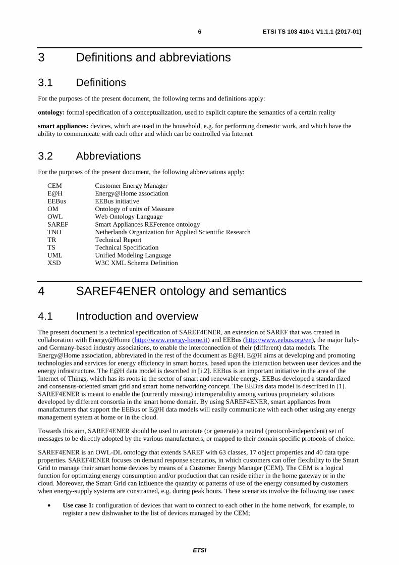
3.1 Definitions For the purposes of the present document, the following terms and definitions apply:
ontology: formal specification of a conceptualization, used to explicit capture the semantics of a certain reality
smart appliances: devices, which are used in the household, e.g. for performing domestic work, and which have the ability to communicate with each other and which can be controlled via Internet
3.2 Abbreviations For the purposes of the present document, the following abbreviations apply:
CEM Customer Energy Manager E@H Energy@Home association EEBus EEBus initiative OM Ontology of units of Measure OWL Web Ontology Language SAREF Smart Appliances REFerence ontology TNO Netherlands Organization for Applied Scientific Research TR Technical Report TS Technical Specification UML Unified Modeling Language XSD W3C XML Schema Definition
4 SAREF4ENER ontology and semantics
4.1 Introduction and overview The present document is a technical specification of SAREF4ENER, an extension of SAREF that was created in collaboration with Energy@Home (http://www.energy-home.it) and EEBus (http://www.eebus.org/en), the major Italy- and Germany-based industry associations, to enable the interconnection of their (different) data models. The Energy@Home association, abbreviated in the rest of the document as E@H. E@H aims at developing and promoting technologies and services for energy efficiency in smart homes, based upon the interaction between user devices and the energy infrastructure. The E@H data model is described in [i.2]. EEBus is an important initiative in the area of the Internet of Things, which has its roots in the sector of smart and renewable energy. EEBus developed a standardized and consensus-oriented smart grid and smart home networking concept. The EEBus data model is described in [1]. SAREF4ENER is meant to enable the (currently missing) interoperability among various proprietary solutions developed by different consortia in the smart home domain. By using SAREF4ENER, smart appliances from manufacturers that support the EEBus or E@H data models will easily communicate with each other using any energy management system at home or in the cloud.
Towards this aim, SAREF4ENER should be used to annotate (or generate) a neutral (protocol-independent) set of messages to be directly adopted by the various manufacturers, or mapped to their domain specific protocols of choice.
SAREF4ENER is an OWL-DL ontology that extends SAREF with 63 classes, 17 object properties and 40 data type properties. SAREF4ENER focuses on demand response scenarios, in which customers can offer flexibility to the Smart Grid to manage their smart home devices by means of a Customer Energy Manager (CEM). The CEM is a logical function for optimizing energy consumption and/or production that can reside either in the home gateway or in the cloud. Moreover, the Smart Grid can influence the quantity or patterns of use of the energy consumed by customers when energy-supply systems are constrained, e.g. during peak hours. These scenarios involve the following use cases:
• Use case 1: configuration of devices that want to connect to each other in the home network, for example, to register a new dishwasher to the list of devices managed by the CEM;
ETSI
ETSI TS 103 410-1 V1.1.1 (2017-01)7
• Use case 2: smart energy management/ (re-)scheduling appliances in certain modes and preferred times using power profiles to optimize energy efficiency and accommodate the customer's preferences;
• Use case 3: monitoring and control of the start and status of the appliances;
• Use case 4: reaction to special requests from the Smart Grid, for example, incentives to consume more or less depending on current energy availability, or emergency situations that require temporary reduction of the power consumption.
These use cases are associated with the user stories described in [i.3], which include, among others, the following examples:
• User wants to do basic settings of his/her devices;
• User wants to know when the washing machine has finished working;
• User wants the washing done by 5:00 p.m. with least electrical power costs;
• User likes to limit his/her own energy consumption up to a defined limit;
• User allows the CEM to reduce the energy consumption of his/her freezer in a defined range for a specific time, if the grid recognizes (severe) stability issues;
• Grid related emergency situations (blackout prevention).
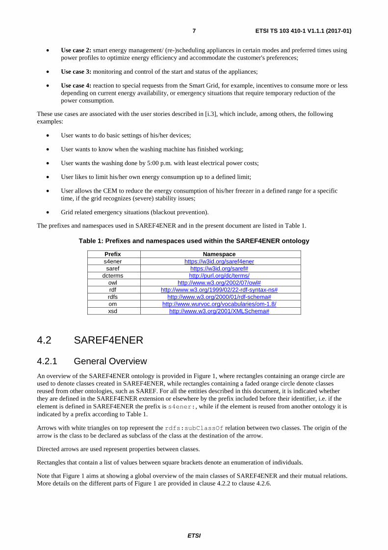
The prefixes and namespaces used in SAREF4ENER and in the present document are listed in Table 1.
Table 1: Prefixes and namespaces used within the SAREF4ENER ontology
Prefix Namespace s4ener https://w3id.org/saref4ener saref https://w3id.org/saref#
dcterms http://purl.org/dc/terms/ owl http://www.w3.org/2002/07/owl# rdf http://www.w3.org/1999/02/22-rdf-syntax-ns# rdfs http://www.w3.org/2000/01/rdf-schema# om http://www.wurvoc.org/vocabularies/om-1.8/ xsd http://www.w3.org/2001/XMLSchema#
4.2 SAREF4ENER
4.2.1 General Overview
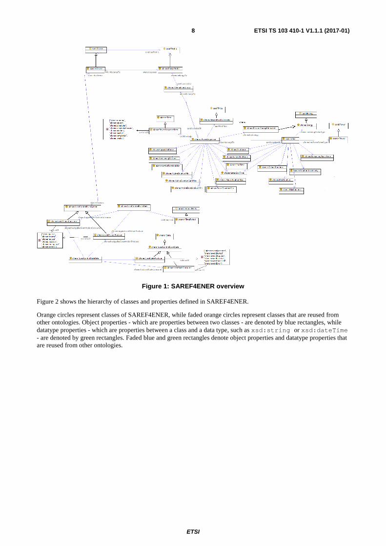
An overview of the SAREF4ENER ontology is provided in Figure 1, where rectangles containing an orange circle are used to denote classes created in SAREF4ENER, while rectangles containing a faded orange circle denote classes reused from other ontologies, such as SAREF. For all the entities described in this document, it is indicated whether they are defined in the SAREF4ENER extension or elsewhere by the prefix included before their identifier, i.e. if the element is defined in SAREF4ENER the prefix is s4ener:, while if the element is reused from another ontology it is indicated by a prefix according to Table 1.
Arrows with white triangles on top represent the rdfs:subClassOf relation between two classes. The origin of the arrow is the class to be declared as subclass of the class at the destination of the arrow.
Directed arrows are used represent properties between classes.
Rectangles that contain a list of values between square brackets denote an enumeration of individuals.
Note that Figure 1 aims at showing a global overview of the main classes of SAREF4ENER and their mutual relations. More details on the different parts of Figure 1 are provided in clause 4.2.2 to clause 4.2.6.
ETSI
ETSI TS 103 410-1 V1.1.1 (2017-01)8
Figure 1: SAREF4ENER overview
Figure 2 shows the hierarchy of classes and properties defined in SAREF4ENER.
Orange circles represent classes of SAREF4ENER, while faded orange circles represent classes that are reused from other ontologies. Object properties - which are properties between two classes - are denoted by blue rectangles, while datatype properties - which are properties between a class and a data type, such as xsd:string or xsd:dateTime - are denoted by green rectangles. Faded blue and green rectangles denote object properties and datatype properties that are reused from other ontologies.

ETSI
ETSI TS 103 410-1 V1.1.1 (2017-01)9
Figure 2: SAREF4ENER class and property hierarchy

ETSI
ETSI TS 103 410-1 V1.1.1 (2017-01)10
4.2.2 Device
A s4ener:Device is a subclass of a saref:Device, i.e. it inherits the properties of the more general saref:Device and extends it with additional properties that are specific for SAREF4ENER. The s4ener:Device class is shown in Figure 3.
Figure 3: Device
Table 2 summarizes the properties that characterize a s4ener:Device.
Table 2: Properties of a Device
Property Definition s4ener:exposes min 0 s4ener:PowerProfile A relationship between a device and its power profile. s4ener:receives min 0 s4ener:LoadControlEventData
A relationship between a device (e.g. an appliance or a smart meter) and a load control event.
s4ener:brandName max 1 xsd:string The name of the brand of a device. Useful where the name of the brand and the vendor differs.
s4ener: deviceCode max 1 xsd:string Device code for the device as defined by the manufacturer. s4ener: s4ee:deviceName max 1 xsd:string Name of the device as defined by the manufacturer. s4ener: hardwareRevision max 1 xsd:string Hardware revision of the device as defined by the
manufacturer. s4ener:manufacturerDescription max 1 xsd:string A description for the device as defined by the manufacturer. s4ener:manufacturerLabel max 1 xsd:string A short label of the device as defined by the manufacturer. s4ener:manufacturerNodeIdentification max 1 xsd:string
A node identification for the device as defined by the manufacturer. This could be used for the identification of a device, even if it was removed from the network and re-joined later with changed node address.
s4ener:powerSource min 0 xsd:string The power source of a device. Possible values are {"unknown", "mainsSinglePhase", "mains3Phase", "battery", "dc"}.
s4ener:serialNumber max 1 xsd:string Serial number of a device as defined by the manufacturer. Usually the same as printed on the case.
s4ener:softwareRevision max 1 xsd:string Software revision of a device as defined by the manufacturer. s4ener:vendorCode max 1 xsd:string Code for the vendor of the device as defined by the
manufacturer. s4ener:vendorName max 1 xsd:string Name of the vendor of the device as defined by the
manufacturer.
4.2.3 Power Profile and Alternatives Group
This clause presents the classes of interest for smart energy management. These classes are used to schedule devices in certain modes and preferred times using power profiles to optimize energy efficiency and accommodate the customer's preferences (i.e. use case 2). These classes are s4ener:PowerProfile, s4ener:Alternative, s4ener:PowerSequence and s4ener:Slot, which are shown in Figure 4.

ETSI
ETSI TS 103 410-1 V1.1.1 (2017-01)11
A s4ener:PowerProfile is a subclass of a saref:Profile, i.e. it inherits the properties of the more general saref:Profile extending it with additional properties that are specific for SAREF4ENER. The s4ener:PowerProfile is used by a s4ener:Device to expose the power sequences that are potentially relevant for the CEM. A s4ener:Device can expose a s4ener:PowerProfile, which consists of one or more alternative plans (s4ener:AlternativesGroup class). A s4ener:AlternativesGroup consists of one or more power sequences (s4ener:PowerSequence class), and a s4ener:PowerSequence consists of one or more slots (s4ener:Slot class). Inversely, a s4ener:Slot belongs to only and exactly one s4ener:PowerSequence, which, in turn, belongs to only and exactly one s4ener:AlternativesGroup, which, in turn, belongs to only and exactly one s4ener:PowerProfile. A s4ener:PowerProfile belongs to only and exactly one s4ener:Device.
Figure 4: Power Profile and Alternatives Group
Table 3 summarizes the properties that characterize a s4ener:PowerProfile and an s4ener:AternativesGroup.

ETSI
ETSI TS 103 410-1 V1.1.1 (2017-01)12
Table 3: Properties of a Power Profile and an AlternativesGroup
Property Definition s4ener:alternativesGroupID exactly 1 xsd:unsignedInt
The endpoint-wide unique identifier for the alternatives group instances provided by a power profile.
s4ener:alternativesCount exactly 1 xsd:integer Number of "alternatives" groups provided by a power profile.
s4ener:nodeRemoteControllable exactly 1 xsd:boolean
Whether the device is configured for remote control by the CEM. This refers to the selection chosen by the user on the remote control feature of the device.
s4ener:supportsReselection exactly 1 xsd:boolean Whether the device restricts the number of sequence re-selections by the CEM. If set to TRUE, there is no restriction, i.e. within a given alternative the CEM may first choose one sequence, alter the selection by configuring another sequence later on, then alter the selection again, etc. If set to FALSE, the device permits the CEM to select a sequence of an alternative only one time.
s4ener:supportsSingleSlotSchedulingOnly exactly 1 xsd:boolean
Whether the device permits the modification of more than one slot per configuration command. If set to TRUE the device does NOT permit this modification.
s4ener:totalSequencesCountMax exactly 1 xsd:unsignedInt
Total number of sequences supported by the device, i.e. the sum of all power sequences across all alternatives.
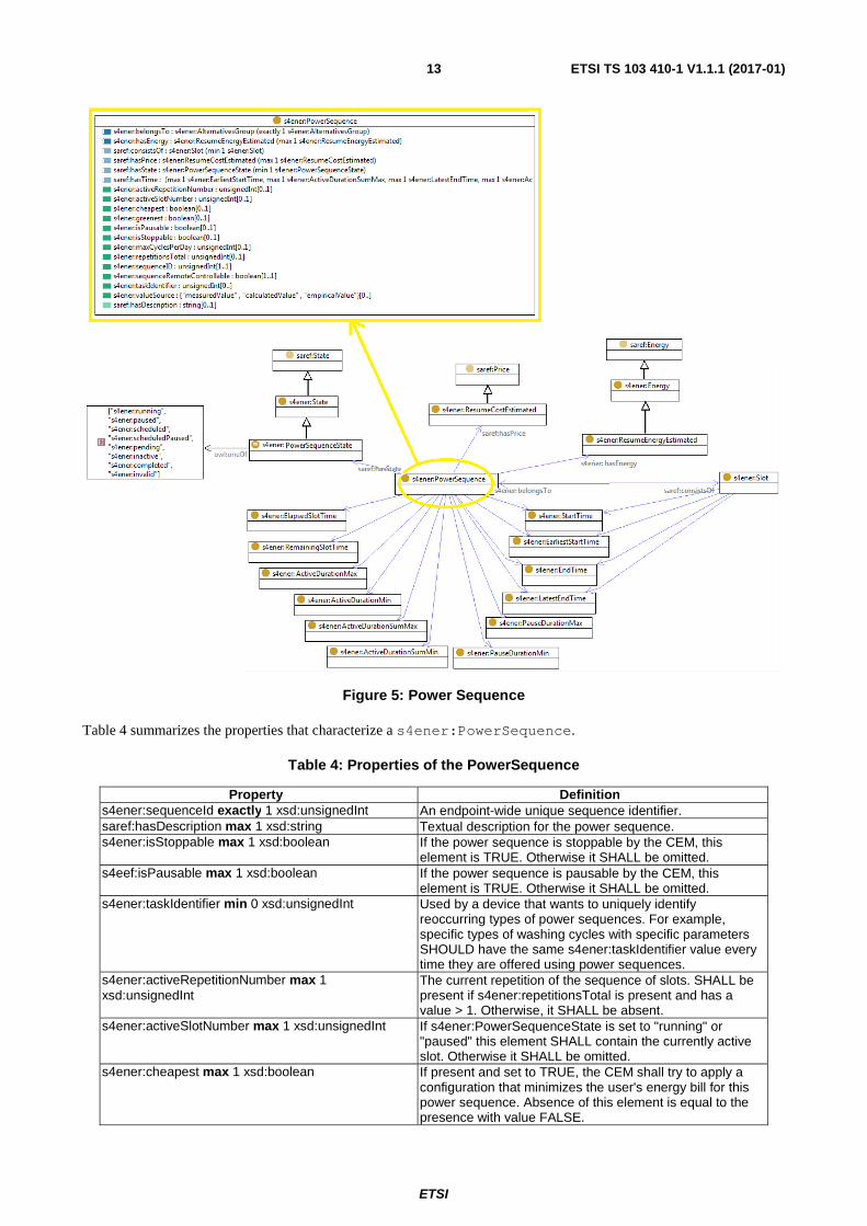
4.2.4 Power Sequence
The s4ener:AlternativesGroup described in clause 4.2.3 consists of one or more power sequences (s4ener:PowerSequence class) and, inversely, a s4ener:PowerSequence belongs to only and exactly one s4ener:AlternativesGroup. Figure 5 shows the details of the s4ener:PowerSequence class.
ETSI
ETSI TS 103 410-1 V1.1.1 (2017-01)13
Figure 5: Power Sequence
Table 4 summarizes the properties that characterize a s4ener:PowerSequence.
Table 4: Properties of the PowerSequence
Property Definition s4ener:sequenceId exactly 1 xsd:unsignedInt An endpoint-wide unique sequence identifier. saref:hasDescription max 1 xsd:string Textual description for the power sequence. s4ener:isStoppable max 1 xsd:boolean If the power sequence is stoppable by the CEM, this
element is TRUE. Otherwise it SHALL be omitted. s4eef:isPausable max 1 xsd:boolean If the power sequence is pausable by the CEM, this
element is TRUE. Otherwise it SHALL be omitted. s4ener:taskIdentifier min 0 xsd:unsignedInt Used by a device that wants to uniquely identify
reoccurring types of power sequences. For example, specific types of washing cycles with specific parameters SHOULD have the same s4ener:taskIdentifier value every time they are offered using power sequences.
s4ener:activeRepetitionNumber max 1 xsd:unsignedInt
The current repetition of the sequence of slots. SHALL be present if s4ener:repetitionsTotal is present and has a value > 1. Otherwise, it SHALL be absent.
s4ener:activeSlotNumber max 1 xsd:unsignedInt If s4ener:PowerSequenceState is set to "running" or "paused" this element SHALL contain the currently active slot. Otherwise it SHALL be omitted.
s4ener:cheapest max 1 xsd:boolean If present and set to TRUE, the CEM shall try to apply a configuration that minimizes the user's energy bill for this power sequence. Absence of this element is equal to the presence with value FALSE.
ETSI
ETSI TS 103 410-1 V1.1.1 (2017-01)14
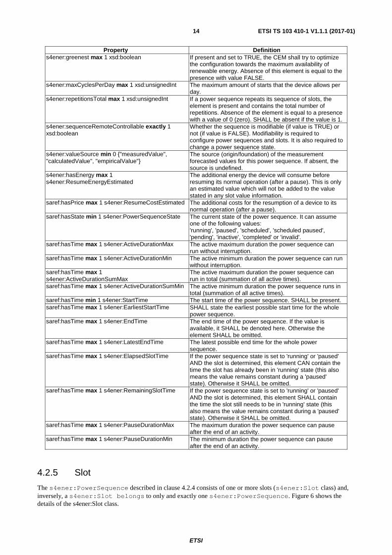
Property Definition s4ener:greenest max 1 xsd:boolean If present and set to TRUE, the CEM shall try to optimize
the configuration towards the maximum availability of renewable energy. Absence of this element is equal to the presence with value FALSE.
s4ener:maxCyclesPerDay max 1 xsd:unsignedInt The maximum amount of starts that the device allows per day.
s4ener:repetitionsTotal max 1 xsd:unsignedInt If a power sequence repeats its sequence of slots, the element is present and contains the total number of repetitions. Absence of the element is equal to a presence with a value of 0 (zero). SHALL be absent if the value is 1.
s4ener:sequenceRemoteControllable exactly 1 xsd:boolean
Whether the sequence is modifiable (if value is TRUE) or not (if value is FALSE). Modifiability is required to configure power sequences and slots. It is also required to change a power sequence state.
s4ener:valueSource min 0 {"measuredValue", "calculatedValue", "empiricalValue"}
The source (origin/foundation) of the measurement forecasted values for this power sequence. If absent, the source is undefined.
s4ener:hasEnergy max 1 s4ener:ResumeEnergyEstimated
The additional energy the device will consume before resuming its normal operation (after a pause). This is only an estimated value which will not be added to the value stated in any slot value information.
saref:hasPrice max 1 s4ener:ResumeCostEstimated
The additional costs for the resumption of a device to its normal operation (after a pause).
saref:hasState min 1 s4ener:PowerSequenceState
The current state of the power sequence. It can assume one of the following values: 'running', 'paused', 'scheduled', 'scheduled paused', 'pending', 'inactive', 'completed' or 'invalid'.
saref:hasTime max 1 s4ener:ActiveDurationMax The active maximum duration the power sequence can run without interruption.
saref:hasTime max 1 s4ener:ActiveDurationMin The active minimum duration the power sequence can run without interruption.
saref:hasTime max 1 s4ener:ActiveDurationSumMax
The active maximum duration the power sequence can run in total (summation of all active times).
saref:hasTime max 1 s4ener:ActiveDurationSumMin The active minimum duration the power sequence runs in total (summation of all active times).
saref:hasTime min 1 s4ener:StartTime The start time of the power sequence. SHALL be present. saref:hasTime max 1 s4ener:EarliestStartTime SHALL state the earliest possible start time for the whole
power sequence. saref:hasTime max 1 s4ener:EndTime The end time of the power sequence. If the value is
available, it SHALL be denoted here. Otherwise the element SHALL be omitted.
saref:hasTime max 1 s4ener:LatestEndTime The latest possible end time for the whole power sequence.
saref:hasTime max 1 s4ener:ElapsedSlotTime If the power sequence state is set to 'running' or 'paused' AND the slot is determined, this element CAN contain the time the slot has already been in 'running' state (this also means the value remains constant during a 'paused' state). Otherwise it SHALL be omitted.
saref:hasTime max 1 s4ener:RemainingSlotTime If the power sequence state is set to 'running' or 'paused' AND the slot is determined, this element SHALL contain the time the slot still needs to be in 'running' state (this also means the value remains constant during a 'paused' state). Otherwise it SHALL be omitted.
saref:hasTime max 1 s4ener:PauseDurationMax The maximum duration the power sequence can pause after the end of an activity.
saref:hasTime max 1 s4ener:PauseDurationMin The minimum duration the power sequence can pause after the end of an activity.
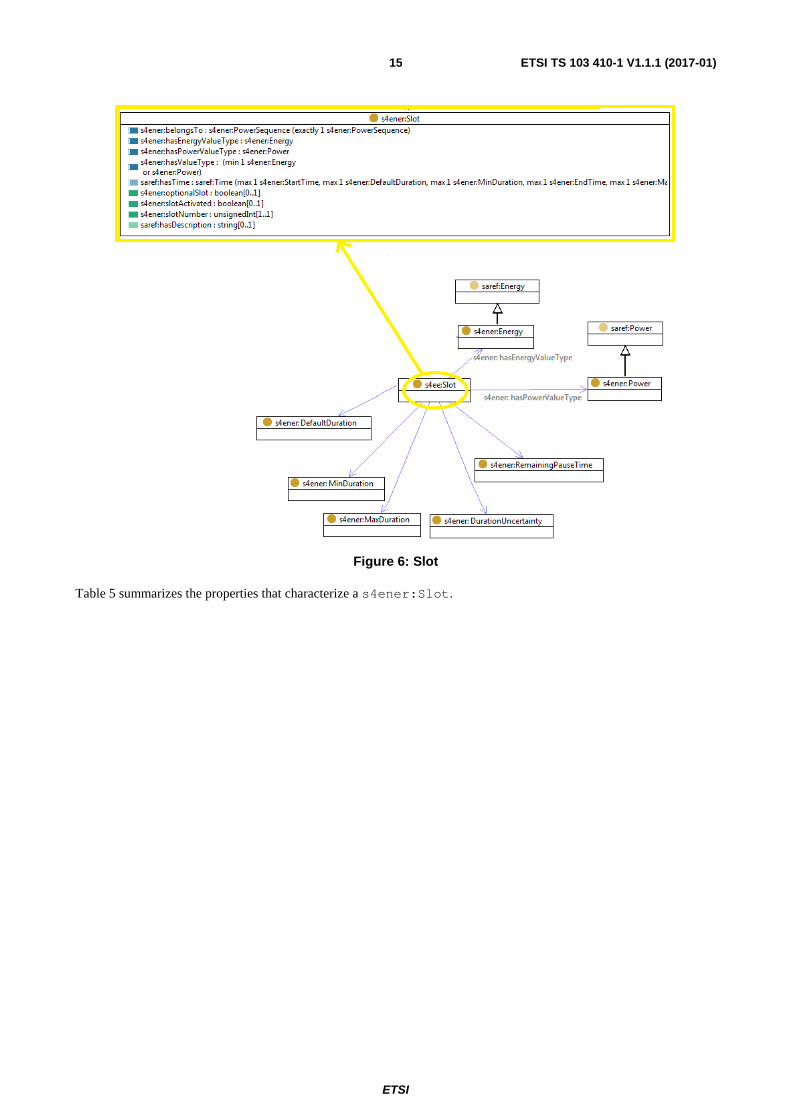
4.2.5 Slot
The s4ener:PowerSequence described in clause 4.2.4 consists of one or more slots (s4ener:Slot class) and, inversely, a s4ener:Slot belongs to only and exactly one s4ener:PowerSequence. Figure 6 shows the details of the s4ener:Slot class.
ETSI
ETSI TS 103 410-1 V1.1.1 (2017-01)15
Figure 6: Slot
Table 5 summarizes the properties that characterize a s4ener:Slot.

ETSI
ETSI TS 103 410-1 V1.1.1 (2017-01)16
Table 5: Properties of a Slot
Property Definition s4ener:slotNumber exactly 1 A power sequence Id-wide unique slot identifier. saref:hasDescription max 1 Textual description for the slot. s4ener:optionalSlot max 1 It is set to TRUE if the slot can be omitted, otherwise the
element SHALL be omitted or set to FALSE. See note 1. s4ener:slotActivated max 1 If the slot is optional, i.e. s4ener:optionalSlot is set to
TRUE, this element reflects the current status of the slot (TRUE = the slot will be executed, FALSE = the slot will not be executed). If the slot is not optional, this element SHALL be absent.
s4ener:hasValueType min 1 (s4ener:Energy or s4ener:Power)
The type of energy or power (subclasses of saref:Energy and saref:Power). The energy can be of type s4ener:EnergyMin, s4ener:EnergyMax, s4ener:EnergyExpected, s4ener:EnergyStandardDeviation or s4ener:EnergySkewness. The power can be of type s4ener:PowerMin, s4ener:PowerMax, s4ener:PowerExpected, s4ener:PowerStandardDeviation or s4ener: Power Skewness.
saref:hasTime max 1 s4ener:DefaultDuration The duration of the slot (in case of 'determined slot'). If the slot has a configurable length, this element SHALL reflect the currently configured length.
saref:hasTime max 1 s4ener:MaxDuration The maximum supported configuration (if the slot has a configurable duration).
saref:hasTime max 1 s4ener:MinDuration The minimum supported configuration (if the slot has a configurable duration). Note: this element applies to the first repetition of the slot number only.
saref:hasTime max 1 s4ener:DurationUncertainty The uncertainty of the duration given in the s4ener:Duration class.
saref:hasTime max 1 s4ener:StartTime The start time of the slot. SHALL be present. saref:hasTime max 1 s4ener:EarliestStartTime SHALL state the earliest possible start time for the slot. saref:hasTime max 1 s4ener:EndTime The end time of the slot. The following equation SHALL
apply: EndTime - StartTime = DefaultDuration. saref:hasTime max 1 s4ener:LatestEndTime The latest possible end time for the slot. saref:hasTime max 1 s4ener:RemainingPauseTime The duration that the current slot permits being paused.
This element SHALL ONLY be present if the power sequence is interruptible (pausable), i.e. saref:isInterrupionPossible has value TRUE.
NOTE 1: This element applies to every repetition of the slot number. NOTE 2: This element applies to the first repetition of the slot number only.
4.2.6 Load control
This clause presents the part of SAREF4ENER that defines how to model events used in, for example, a direct load management and power curtailing scenarios (i.e. use case 4). The classes of interest are s4ener:LoadControlEventData, s4ener:LoadControlEventAction, s4ener:LoadControlStateData and s4ener:LoadControlState, as shown in Figure 7.

ETSI
ETSI TS 103 410-1 V1.1.1 (2017-01)17
Figure 7: Load Control
The s4ener: LoadControlEventData class is used to represent overload warning severity level and related load control commands to a device. It is characterized by an event ID and a timestamp that represents the time the event information instance was created or received, and the time period that denotes the period of validity of the event. For example, 5 minutes ago an event was received which says that it shall take effect tomorrow from 14:00 to 15:30. In this event the timestamp is "5 minutes ago" and time period is "tomorrow from 14:00 to 15:30".
The s4ener:LoadControlEventAction class expresses the type of actions to be performed as a consequence of a load control event. A s4ener:LoadControlEventAction can be of type "consume" or "produce" to denote consumption or production of energy or power. Values for both consume and produce actions can be s4ener:emergency, s4ener:increase, s4ener:normal, s4ener:pause, s4ener:reduce, s4ener:resume.
The s4ener: LoadControlStateData class expresses the data about the state of an event and is characterized by the same event ID used in the s4ener:LoadControlEventData class, as well as a timestamp, and it is associated to the class s4ener:LoadControlState, which can be of type "consume" or "produce" - analogously to a load control event action – and expresses the possible states of a load control event. Values for both consume and produce load control states can be s4ener:eventAccepted, s4ener:eventStarted, s4ener:eventStopped, s4ener:eventRejected, s4ener:eventCancelled, or s4ener:eventError.
4.3 Observations about SAREF4ENER The extension for the energy domain presented in the present document was originally called SAREF4EE, since it was created for the Energy@Home and EEBus associations [i.1]. However, in the present document the extension has been renamed to SAREF4ENER according to the naming convention for SAREF extensions adopted in the ETSI TR 103 411 [i.4] (i.e. SAREF4XXXX, where XXXX are letters that describe the domain for which the extension was created).
ETSI
ETSI TS 103 410-1 V1.1.1 (2017-01)18
The present document describes the concepts for the use case 2 (smart energy management), and the use case 4 (representation of events in case of direct load management and power curtailing) elaborated in clause 5.1.1 in ETSI TR 103 411 [i.4]. However, the present document does not include the concepts for the use case 1 (exchange configuration information of devices in order to connect to each other) and the use case 3 (monitor and control the start and status of the appliances), since these concepts at the time of publication are under discussion between the Energy@Home and EEBus associations and NOT yet included in the SPINE specification in [1]. For the sake of completeness, these concepts are included in the annex B of the present document as informative, but they are NOT part of the current release of SAREF4ENER.
ETSI
ETSI TS 103 410-1 V1.1.1 (2017-01)19
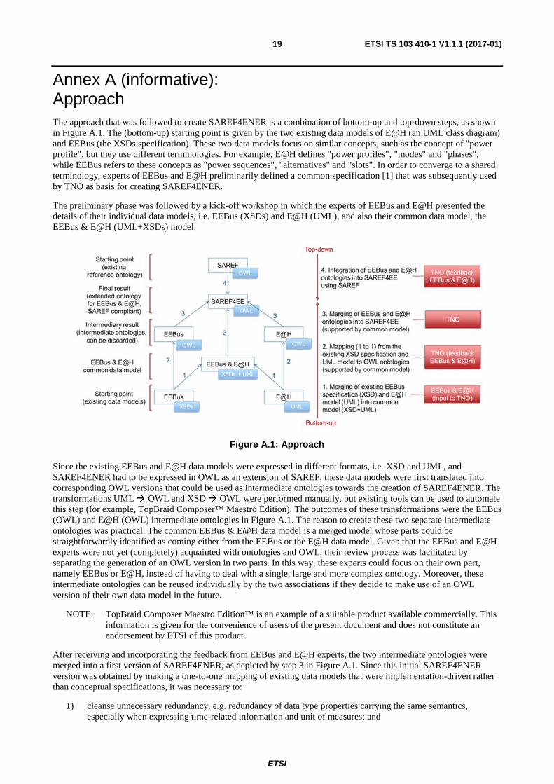
Annex A (informative): Approach The approach that was followed to create SAREF4ENER is a combination of bottom-up and top-down steps, as shown in Figure A.1. The (bottom-up) starting point is given by the two existing data models of E@H (an UML class diagram) and EEBus (the XSDs specification). These two data models focus on similar concepts, such as the concept of "power profile", but they use different terminologies. For example, E@H defines "power profiles", "modes" and "phases", while EEBus refers to these concepts as "power sequences", "alternatives" and "slots". In order to converge to a shared terminology, experts of EEBus and E@H preliminarily defined a common specification [1] that was subsequently used by TNO as basis for creating SAREF4ENER.
The preliminary phase was followed by a kick-off workshop in which the experts of EEBus and E@H presented the details of their individual data models, i.e. EEBus (XSDs) and E@H (UML), and also their common data model, the EEBus & E@H (UML+XSDs) model.
Figure A.1: Approach
Since the existing EEBus and E@H data models were expressed in different formats, i.e. XSD and UML, and SAREF4ENER had to be expressed in OWL as an extension of SAREF, these data models were first translated into corresponding OWL versions that could be used as intermediate ontologies towards the creation of SAREF4ENER. The transformations UML � OWL and XSD � OWL were performed manually, but existing tools can be used to automate this step (for example, TopBraid Composer™ Maestro Edition). The outcomes of these transformations were the EEBus (OWL) and E@H (OWL) intermediate ontologies in Figure A.1. The reason to create these two separate intermediate ontologies was practical. The common EEBus & E@H data model is a merged model whose parts could be straightforwardly identified as coming either from the EEBus or the E@H data model. Given that the EEBus and E@H experts were not yet (completely) acquainted with ontologies and OWL, their review process was facilitated by separating the generation of an OWL version in two parts. In this way, these experts could focus on their own part, namely EEBus or E@H, instead of having to deal with a single, large and more complex ontology. Moreover, these intermediate ontologies can be reused individually by the two associations if they decide to make use of an OWL version of their own data model in the future.
NOTE: TopBraid Composer Maestro Edition™ is an example of a suitable product available commercially. This information is given for the convenience of users of the present document and does not constitute an endorsement by ETSI of this product.
After receiving and incorporating the feedback from EEBus and E@H experts, the two intermediate ontologies were merged into a first version of SAREF4ENER, as depicted by step 3 in Figure A.1. Since this initial SAREF4ENER version was obtained by making a one-to-one mapping of existing data models that were implementation-driven rather than conceptual specifications, it was necessary to:
1) cleanse unnecessary redundancy, e.g. redundancy of data type properties carrying the same semantics, especially when expressing time-related information and unit of measures; and

ETSI
ETSI TS 103 410-1 V1.1.1 (2017-01)20
2) create axioms that were absent in the original data models. While doing so, a top-down approach starting from SAREF was taken, as depicted by step 4 in Figure A.1. SAREF contains concepts that are rather high-level and needed further specialization into a finer-grained level of detail to accommodate the specific requirements of the EEBus and E@H use cases.
Therefore, when creating SAREF4ENER, classes and properties of SAREF were reused and specialized where possible, while SAREF was extended with new classes and properties where it did not suffice for the purpose.
In particular:
• Only a subset of concepts defined in SAREF was reused, i.e. saref:Device, saref:Profile, saref:State, saref:Energy, saref:Power, saref:UnitOfMeasure and saref:Time.
• The saref:Device and saref:Profile classes were specialized in the more specific s4ener:Device and s4ener:PowerProfile subclasses, respectively. Devices and power profiles in SAREF4ENER have specific properties for EEbus and E@H that do not apply to all SAREF devices and profiles.
ETSI
ETSI TS 103 410-1 V1.1.1 (2017-01)21
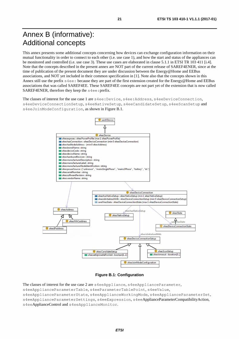
Annex B (informative): Additional concepts This annex presents some additional concepts concerning how devices can exchange configuration information on their mutual functionality in order to connect to each other (i.e. use case 1), and how the start and status of the appliances can be monitored and controlled (i.e. use case 3). These use cases are elaborated in clause 5.1.1 in ETSI TR 103 411 [i.4]. Note that the concepts described in the present annex are NOT part of the current release of SAREF4ENER, since at the time of publication of the present document they are under discussion between the Energy@Home and EEBus associations, and NOT yet included in their common specification in [1]. Note also that the concepts shown in this Annex still use the prefix s4ee: because they are part of the first extension created for the Energy@Home and EEBus associations that was called SAREF4EE. These SAREF4EE concepts are not part yet of the extension that is now called SAREF4ENER, therefore they keep the s4ee:prefix.
The classes of interest for the use case 1 are s4ee:Device, s4ee:Address, s4eeDeviceConnection, s4eeDeviceConnectionSetup, s4eeNativeSetup, s4eeCandidateSetup, s4eeScanSetup and s4eeJoinModeConfiguration, as shown in Figure B.1.
Figure B.1: Configuration
The classes of interest for the use case 2 are s4eeAppliance, s4eeApplianceParameter, s4eeApplianceParameterTable, s4eeParameterTablePoint, s4eeValue, s4eeApplianceParameterState, s4eeApplianceWorkingMode, s4eeApplianceParameterSet, s4eeApplianceParameterSettings, s4eeExpression, s4eeApplianceParameterCompatibilityAction, s4eeApplianceControl and s4eeApplianceMonitor.
ETSI
ETSI TS 103 410-1 V1.1.1 (2017-01)22
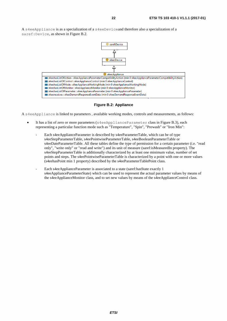
A s4eeAppliance is as a specialization of a s4eeDeviceand therefore also a specialization of a saref:Device, as shown in Figure B.2.
Figure B.2: Appliance
A s4eeAppliance is linked to parameters , available working modes, controls and measurements, as follows:
• It has a list of zero or more parameters (s4eeApplianceParameter class in Figure B.3), each representing a particular function mode such as "Temperature", "Spin", "Prewash" or "Iron Min":
- Each s4eeApplianceParameter is described by s4eeParameterTable, which can be of type s4eeStepParameterTable, s4eePointwiseParameterTable, s4eeBooleanParameterTable or s4eeDateParameterTable. All these tables define the type of permission for a certain parameter (i.e. "read only", "write only" or "read and write") and its unit of measure (saref:isMeasuredIn property). The s4eeStepParameterTable is additionally characterized by at least one minimum value, number of set points and steps. The s4eePointwiseParameterTable is characterized by a point with one or more values (s4eehasPoint min 1 property) described by the s4eeParameterTablePoint class.
- Each s4eeApplianceParameter is associated to a state (saref:hasState exactly 1 s4eeApplianceParameterState) which can be used to represent the actual parameter values by means of the s4eeApplianceMonitor class, and to set new values by means of the s4eeApplianceControl class.

ETSI
ETSI TS 103 410-1 V1.1.1 (2017-01)23
Figure B.3: ApplianceParameter
• It has a list of zero or more working modes (s4eeApplianceWorkingMode class in Figure B.4) each representing a particular working mode such as "Synthetics", "Mix 30" or "Super Cool":
- A working mode has an ID (s4eeworkingModeId exactly 1 property), a name (saref:hasName exactly 1 property) and a list of zero or more sets (s4eeApplianceParameterSet class) representing the sets of enabled parameters for that working mode. A s4ee:ApplianceParameterSet can have zero or more settings (s4eeApplianceParameterSettings class)and is selected according to certain conditions defined in the s4eeExpression class. The set "0" is the default set and is selected when no condition is true:
� The s4ee:ApplianceParameterSettings class is characterized by the parameter ID (s4eeparameterId exactly 1 property) and a number of values for that parameter that are subclass of the s4eeValue class, i.e. s4eeAvoidedValue (list of not admitted values), s4ee:DefaultValue (default value of the parameter), s4eeMaxValue (maximum value that the parameter could be set) and s4eeMinValue classes (minimum value that the parameter could be set). The s4eeApplianceParameterSettings class also has a boolean property to specify whether the settings under consideration are active or not (s4eeisActive property).
� The s4ee:Expression class is characterized by a value (s4eehasValueType exactly 1 property), the parameter ID (s4eeparameterId exactly 1 property) that identifies the parameter whose current set point has to be compared, a math operator s4eemathOperator exactly 1 property) such as "==" , "!=" , ">" , "<" to define set points equal, different, above or below the expression value, and logical connectives (s4eelogicalConnective min 0 property) such as "AND" and "OR" that could be used to connect different expressions.

ETSI
ETSI TS 103 410-1 V1.1.1 (2017-01)24
Figure B.4: ApplianceWorkingMode
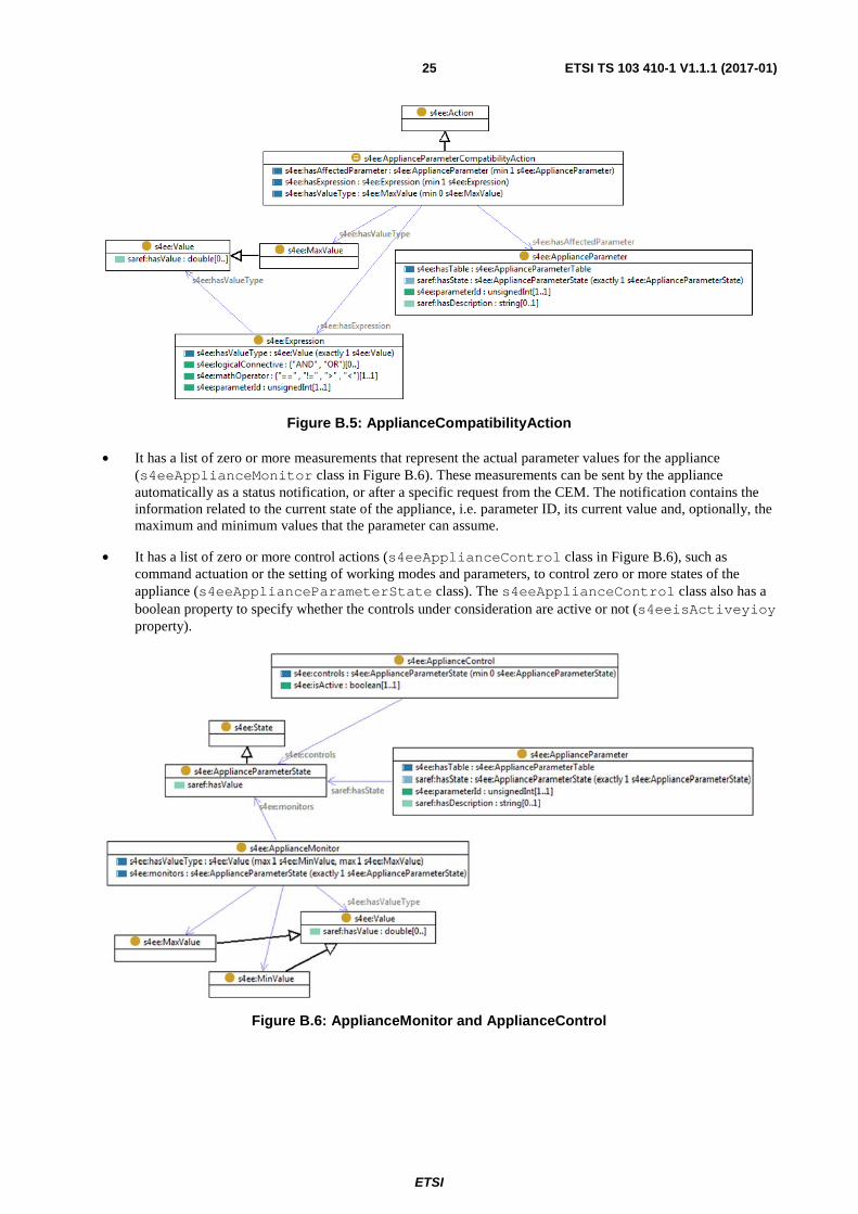
• It has a list of zero or more actions to be executed in case of incompatibility with other parameters (s4ee:ApplianceParameterCompatibilityAction class in Figure B.5):
- The s4eeApplianceParameterCompatibilityAction class specifies incompatible parameters (s4eehasAffectedParameter min 1 property), and has at least one expression (s4eehasExpression min 1 property). If this expression turns TRUE, then one of the following types of actions will be executed:
� s4eeaction_1_reset_to_OFF_value (reset).
� s4eeaction_2_disabled (disabled).
� s4eeaction_3_set_to_MaxValue (set to maximum value).
� s4eeaction_4_set_to_default_value (set to default value).
The property s4eehasValue min 0 s4eeMaxValue expresses the maximum value to be used in case of s4eeaction_3_set_to_MaxValue.
ETSI
ETSI TS 103 410-1 V1.1.1 (2017-01)25
Figure B.5: ApplianceCompatibilityAction
• It has a list of zero or more measurements that represent the actual parameter values for the appliance (s4eeApplianceMonitor class in Figure B.6). These measurements can be sent by the appliance automatically as a status notification, or after a specific request from the CEM. The notification contains the information related to the current state of the appliance, i.e. parameter ID, its current value and, optionally, the maximum and minimum values that the parameter can assume.
• It has a list of zero or more control actions (s4eeApplianceControl class in Figure B.6), such as command actuation or the setting of working modes and parameters, to control zero or more states of the appliance (s4eeApplianceParameterState class). The s4eeApplianceControl class also has a boolean property to specify whether the controls under consideration are active or not (s4eeisActiveyioy property).
Figure B.6: ApplianceMonitor and ApplianceControl
ETSI
ETSI TS 103 410-1 V1.1.1 (2017-01)26
Annex C (informative): Bibliography
• ETSI TS 103 264: "SmartM2M; Smart Appliances; Reference Ontology and oneM2M mapping".
• ETSI TS 103 267: "SmartM2M; Smart Appliances; Communication Framework".
• ETSI TS 102 689: "Machine-to-Machine communications (M2M); M2M Service Requirements".
• oneM2M TS-0001: "Functional Architecture".
• oneM2M TS-0002: "Requirements".
• ETSI, European Commission and TNO: "Study on Semantic Assets for Smart Appliances Interoperability", final report, April 2015.
NOTE: Available at https://sites.google.com/site/smartappliancesproject/deliverables.
ETSI
ETSI TS 103 410-1 V1.1.1 (2017-01)27
History
Document history
V1.1.1 January 2017 Publication