etsi etr 019 technical august 1996 report · page 2 etr 019: august 1996 whilst every care has been...
TRANSCRIPT
ETSI ETR 019
TECHNICAL August 1996
REPORT Second Edition
Source: ETSI/TC-TM Reference: RTR/TM-04030
ICS: 33.060.30
Key words: DRRS, SDH, STM, radio, transmission
Transmission and Multiplexing (TM);Specification of new generation high capacity digital radio
systems carrying 2xSTM-1 Synchronous Digital Hierarchy (SDH)signals in frequency bands with 40 MHz
channel spacing
ETSI
European Telecommunications Standards Institute
ETSI Secretariat
Postal address: F-06921 Sophia Antipolis CEDEX - FRANCEOffice address: 650 Route des Lucioles - Sophia Antipolis - Valbonne - FRANCEX.400: c=fr, a=atlas, p=etsi, s=secretariat - Internet: [email protected]
Tel.: +33 92 94 42 00 - Fax: +33 93 65 47 16
Copyright Notification: No part may be reproduced except as authorized by written permission. The copyright and theforegoing restriction extend to reproduction in all media.
© European Telecommunications Standards Institute 1996. All rights reserved.

Page 2ETR 019: August 1996
Whilst every care has been taken in the preparation and publication of this document, errors in content,typographical or otherwise, may occur. If you have comments concerning its accuracy, please write to"ETSI Editing and Committee Support Dept." at the address shown on the title page.

Page 3ETR 019: August 1996
Contents
Foreword .......................................................................................................................................................5
1 Scope ..................................................................................................................................................7
2 References..........................................................................................................................................7
3 Symbols and abbreviations .................................................................................................................83.1 Symbols ...............................................................................................................................83.2 Abbreviations .......................................................................................................................8
4 Considerations regarding the system proposals .................................................................................94.1 General system characteristics............................................................................................94.2 Specific system characteristics..........................................................................................13
4.2.1 System A .......................................................................................................134.2.1.1 Compatibility requirements ..................................................13
4.2.1.1.1 Compatibility with analogue channelson the same route.................................13
4.2.1.1.2 Compatibility with 16 QAM systems onthe same route......................................13
4.2.1.1.3 Compatibility with analogue/digitalsystems at radio node...........................13
4.2.2 System B .......................................................................................................144.2.2.1 Compatibility requirements ..................................................14
4.2.2.1.1 Compatibility with analogue channelson the same route.................................14
4.2.2.1.2 Compatibility with 16 QAM systems onthe same route......................................14
4.2.2.1.3 Compatibility with analogue/digitalsystems at radio node...........................15
4.2.3 System C.......................................................................................................154.2.3.1 Compatibility requirements ..................................................15
4.2.3.1.1 Compatibility with analogue channelson the same route.................................15
4.2.3.1.2 Compatibility with 16 QAM systems onthe same route......................................15
4.2.3.1.3 Compatibility with analogue/digitalsystems at radio node...........................15
4.2.3.2 Branching arrangement in frequency re-use operation .......164.2.3.3 Frequency re-use system configuration ..............................17
5 Remarks on performance of CCDP systems....................................................................................185.1 Cross-Polar Interference Canceller (XPIC) Improvement Factor (XIF) .............................185.2 Antenna XPD .....................................................................................................................185.3 Characterisation and measurement of XPIC performance................................................19
6 Technical parameters........................................................................................................................216.1 Generality...........................................................................................................................216.2 Network and system considerations ..................................................................................216.3 Table of technical parameters ...........................................................................................226.4 Informative notes ...............................................................................................................30
6.4.1 Branching/feeder/antenna requirements.......................................................306.4.1.1 Cross Polar Discrimination (XPD) .......................................306.4.1.2 Intermodulation products .....................................................306.4.1.3 Interport isolation .................................................................306.4.1.4 Return loss...........................................................................30
6.4.2 Automatic Transmit Power Control (ATPC) ..................................................306.5 Figures ...............................................................................................................................31

Page 4ETR 019: August 1996
6.5.1 Figures relevant to system A ........................................................................ 316.5.2 Figures relevant to system B ........................................................................ 346.5.3 Figures relevant to system C ........................................................................ 36
Annex A: Bibliography............................................................................................................................ 38
History ......................................................................................................................................................... 39
Page 5ETR 019: August 1996
Foreword
This ETSI Technical Report (ETR) has been produced by the Transmission and Multiplexing (TM)Technical Committee of the European Telecommunications Standards Institute (ETSI).
ETRs are informative documents resulting from ETSI studies which are not appropriate for EuropeanTelecommunication Standard (ETS) or Interim European Telecommunication Standard (I-ETS) status. AnETR may be used to publish material which is either of an informative nature, relating to the use or theapplication of ETSs or I-ETSs, or which is immature and not yet suitable for formal adoption as an ETS oran I-ETS.

Page 6ETR 019: August 1996
Blank Page
Page 7ETR 019: August 1996
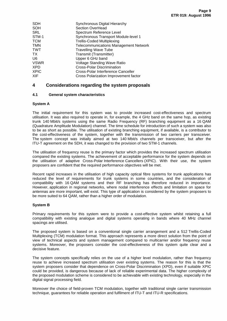
1 Scope
This ETSI Technical Report (ETR) provides proposals for a new generation of high capacity Digital RadioRelay Systems (DRRS) carrying 2 Synchronous Transport Module -1 (2xSTM-1) Synchronous DigitalHierarchy (SDH) signals in frequency bands with 40 MHz channel spacing.
Three different system concepts have been proposed.
The main aspects of each of these systems are described in clause 4, in order to provide a betterunderstanding of commonalities and differences among them.
In clause 5 remarks on performance of Co-Channel Dual Polar (CCDP) systems are reported, becausetwo systems among the proposed ones make use of frequency reuse.
A list of systems parameters and the values which have been proposed for the three systems are given inclause 6.
The topics mentioned "under study" identify areas needing further investigation.
2 References
This ETR incorporates by dated or undated reference, provisions from other publications. Theseinformative references are cited at the appropriate places in the text and the publications are listedhereafter. For dated references, subsequent amendments to or revisions of any of these publicationsapply to this ETR only when incorporated in it by amendment or revision. For undated references, thelatest edition of the publication referred to applies.
[1] ITU-R Recommendation F. 635: "Radio frequency channel arrangements basedon a homogeneous pattern for radio relay systems operating in the 4 GHzband".
[2] ITU-R Recommendation F. 384: "Radio frequency channel arrangements formedium and high capacity analogue or digital radio relay systems operqating inthe upper 6GHz band".
[3] ITU-R Recommendation F. 387: "Radio frequency channel arrangements forradio relay systems operating in the 11 GHz band".
[4] ITU-R Recommendation F.750: "Architectures and functional aspects ofradio-relay systems for SDH-based networks".
[5] ITU-R Recommendation F. 751: "Transmission characteristics and performancerequirements of radio-relay systems for SDH-based networks".
[6] ETS 300 019, Parts 1 and 2: "Equipment Engineering (EE); Environmentalconditions and environmental tests for telecommunications equipment Part 1:Classification of environmental conditions and Part 2: Specification ofenvironmental tests".
[7] ETS 300 132: "Equipment Engineering (EE); Power supply interface at the inputto telecommunications equipment".
[8] CEPT Recommendation T/L 04-04: "Harmonisation of 140 Mbit/s digital radiorelay systems for operation below 10 GHz utilising 64 QAM at about 30 MHzspacing".
[9] ITU-T Recommendation G.708 (1990): "Network node interface for thesynchronous digital hierarchy".
[10] ITU-T Recommendation G.709 (1990): "Synchronous multiplexing structure".

Page 8ETR 019: August 1996
[11] ITU-T Recommendation G.773: "Protocol suites for Q-Interfaces formanagement of transmission systems".
[12] ITU-T Recommendation G.784: "Synchronous Digital Hierarchy (SDH)management".
[13] ITU-R Recommendation F. 1099: "Radio frequency channel arrangements forhigh capacity digital radio relay systems in the 5 GHz (4 400 - 5 000 MHz)band".
[14] prETS 300 635: "Transmission and Multiplexing (TM); Synchronous DigitalHierarchy (SDH); Radio specific functional blocks for transmission ofMx STM-N".
[15] ITU-T Recommendation G.703: "Physical/electrical characteristics ofhierarchical digital interfaces".
[16] ETS 300 119: "Equipment Engineering (EE); European telecommunicationstandard for equipment practice".
[17] ETS 300 234: "Transmission and Multiplexing (TM); High capacity digital radiorelay systems carrying 1 x STM-1 signals and operating in frequency trends withabout 30 MHz channel spacing and alternated arrangements".
3 Symbols and abbreviations
3.1 Symbols
For the purposes of this ETR, the following symbols apply:
dB decibeldBm decibel relative to 1 mWGHz GigaHertzkm kilometreMbit/s Mega-bit per secondMHz MegaHertzm/s metres per secondns nanosecondppm parts per millionW/m² Watts per square metre
3.2 Abbreviations
For the purposes of this ETR, the following abbreviations apply:
ACDP Adjacent Channel Dual PolarATPC Automatic Transmit Power ControlBB BaseBandBER Bit Error RateCCDP Co-Channel Dual PolarC/I Carrier to Interference (ratio)DRRS Digital Radio Relay SystemETS European Telecommunication StandardETSI European Telecommunications Standards InstituteIF Intermediate FrequencyIF/RF Intermediate Frequency/Radio FrequencyLO Local OscillatorL4 Lower 4 GHz bandPRBS Pseudo-Random Binary SequenceQAM Quadrature Amplitude ModulationRF Radio FrequencyRX Receive (Receiver)
Page 9ETR 019: August 1996
SDH Synchronous Digital HierarchySOH Section OverHeadSRL Spectrum Reference LevelSTM-1 Synchronous Transport Module-level 1TCM Trellis-Coded MultiplexingTMN Telecommunications Management NetworkTWT Travelling Wave TubeTX Transmit (Transmitter)U6 Upper 6 GHz bandVSWR Voltage Standing Wave RatioXPD Cross-Polar DiscriminationXPIC Cross-Polar Interference CancellerXIF Cross Polarization Improvement factor
4 Considerations regarding the system proposals
4.1 General system characteristics
System A
The initial requirement for this system was to provide increased cost-effectiveness and spectrumutilisation. It was also required to operate in, for example, the 4 GHz band on the same hop, as existingtrunk 140 Mbit/s systems using the same Radio Frequency (RF) branching equipment as a 16 QAM(Quadrature Amplitude Modulation) channel. The time schedule for introduction of such a system was alsoto be as short as possible. The utilisation of existing branching equipment, if available, is a contributor tothe cost-effectiveness of the system, together with the transmission of two carriers per transceiver.The system concept was initially aimed at two 140 Mbit/s channels per transceiver, but after theITU-T agreement on the SDH, it was changed to the provision of two STM-1 channels.
The utilisation of frequency reuse is the primary factor which provides the increased spectrum utilisationcompared the existing systems. The achievement of acceptable performance for the system depends onthe utilisation of adaptive Cross-Polar Interference Cancellers (XPIC). With their use, the systemproposers are confident that the required performance objectives will be met.
Recent rapid increases in the utilisation of high capacity optical fibre systems for trunk applications hasreduced the level of requirements for trunk systems in some countries, and the consideration ofcompatibility with 16 QAM systems and their RF branching has therefore reduced in importance.However, application in regional networks, where nodal interference effects and limitation on space forantennas are more important, will exist. This type of application is considered by the system proposers tobe more suited to 64 QAM, rather than a higher order of modulation.
System B
Primary requirements for this system were to provide a cost-effective system whilst retaining a fullcompatibility with existing analogue and digital systems operating in bands where 40 MHz channelspacings are utilised.
The proposed system is based on a conventional single carrier arrangement and a 512 Trellis-CodedMultiplexing (TCM) modulation format. This approach represents a more direct solution from the point ofview of technical aspects and system management compared to multicarrier and/or frequency reusesystems. Moreover, the proposers consider the cost-effectiveness of this system quite clear and adecisive feature.
The system concepts specifically relies on the use of a higher level modulation, rather than frequencyreuse to achieve increased spectrum utilisation over existing systems. The reason for this is that thesystem proposers consider that dependence on Cross-Polar Discrimination (XPD), even if suitable XPICcould be provided, is dangerous because of lack of reliable experimental data. The higher complexity ofthe proposed modulation scheme is considered to be achievable with existing technology, especially in thedigital signal processing field.
Moreover the choice of field-proven TCM modulation, together with traditional single carrier transmissiontechnique, guarantees for reliable operation and fulfilment of ITU-T and ITU-R specifications.
Page 10ETR 019: August 1996
System C
Primary requirements of this system are to provide 2xSTM-1 capacity for each 40 MHz channel, where therelative channel plans in the previous generation equipment provide a transmission capacity of 140 Mbit/swith alternated polarization, whilst retaining the following objectives:
- full compatibility with existing analogue and digital systems;- accordance with ITU-R Recommendations;- same performance on the same hops of the previous generation equipment.
The system concept specifically relies on the use of the relatively low level modulation scheme 32 QAM,used together with a baseband cross-polar interference canceller to obtain frequency reuse.
The most relevant advantage of this solution is that a 32 QAM system has a slightly lower system gain(using same RF devices) with respect to a 16 QAM system of the same capacity, whereas the signaturecharacteristic may be also better. This fact allows the possibility of the reuse of same infrastructures andsites of the 16 QAM/140 Mbit/s systems with, as a consequence, a very effective impact on the cost of thecomplete link.
Moreover, in principle, this system allows the reuse of already installed transceivers of the previousgeneration.
All the previous advantages are achievable on the assumption that the XPIC device gives a cross-polarinterference reduction factor high enough to cancel the effect of the reused cross-polar channel adversepropagation conditions.
This assumption is now confirmed not only by many laboratory tests, but also by means of successfulexperimental hop results already available.
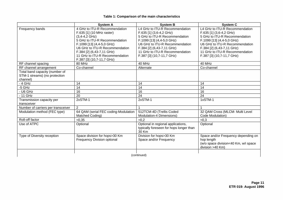
The main aspects of each of this systems are listed in table 1, in order to provide a better understandingof commonalities and differences among them.
Page 11ETR 019: August 1996
Table 1: Comparison of the main characteristics
System A System B System CFrequency bands 4 GHz to ITU-R Recommendation
F.635 [1] (10 MHz raster)(3,4-4,2 GHz)5 GHz to ITU-R RecommendationF.1099 [13] (4,4-5,0 GHz)U6 GHz to ITU-R RecommendationF.384 [2] (6,43-7,11 GHz)11 GHz to ITU-R RecommendationF.387 [3] (10,7-11,7 GHz)
L4 GHz to ITU-R RecommendationF.635 [1] (3,6-4,2 GHz)5 GHz to ITU-R RecommendationF.1099 [13] (4,4-5,0 GHz)U6 GHz to ITU-R RecommendationF.384 [2] (6,43-7,11 GHz)11 GHz to ITU-R RecommendationF.387 [3] (10,7-11,7 GHz)
L4 GHz to ITU-R RecommendationF.635 [1] (3,6-4,2 GHz)5 GHz to ITU-R RecommendationF.1099 [13] (4,4-5,0 GHz)U6 GHz to ITU-R RecommendationF.384 [2] (6,43-7,11 GHz)11 GHz to ITU-R RecommendationF.387 [3] (10,7-11,7 GHz)
RF channel spacing 80 MHz 40 MHz 40 MHzRF channel arrangement Co-channel Alternate Co-channelTotal band capacity (number ofSTM-1 streams) (no protectionchannel)- 4 GHz 14 14 14-5 GHz 14 14 14- U6 GHz 16 16 16- 11 GHz 20 24 24Transmission capacity pertransceiver
2xSTM-1 2xSTM-1 1xSTM-1
Number of carriers per transceiver 2 1 1Modulation method (FEC type) 64 QAM (serial FEC coding-Modulation
Matched Coding)512TCM-4D (Trellis CodedModulation-4 Dimensions)
32 QAM Cross (MLCM- Multi LevelCode Modulation)
Roll-off factor ≈0,35 ≈0,2 ≈0,3Use of ATPC Optional Optional in regional applications,
typically foreseen for hops longer than30 Km
Optional
Type of Diversity reception Space division for hops>30 KmFrequency Division optional
Division for hops>30 KmSpace and/or Frequency
Space and/or Frequency depending onhop length(w/o space division<40 Km, w/i spacedivision >40 Km)
(continued)

Page 12ETR 019: August 1996
Table 1 (concluded): Comparison of the main characteristics
System A System B System CType of combiner IF (one common for the 2 subcarriers
per RX)IF IF or Baseband
XPIC Yes No (Not applicable) YesProtection switching Optional per subcarrier Per carrier One STBY channel per polarizationSystem available for networkintroduction
1992, 1st quarter 1996 1995
Date of the introduction of thesystem concept into the draft report
Thessaloniki 11/89 Thessaloniki 11/89 Athens 12/91
Date of the last revision of systemparameters
Vouliagmeni 5/95 Chester 10/94 Chester 10/94

Page 13ETR 019: August 1996
4.2 Specific system characteristics
4.2.1 System A
4.2.1.1 Compatibility requirements
Relevant system parameters assumed are:
Digital system: 2x155 Mbit/sTransmit spectrum: figure A2
Output power per carrier: +28 dBmAnalogue system: 2 700 voice channels
Transmit power: +43 dBm
4.2.1.1.1 Compatibility with analogue channels on the same route
- 4 GHz band: not relevant;- U6 GHz and 11 GHz bands: yes for RF channel separation > 80 MHz.
The following interference levels result for parallel operation in the highest base band channel of theanalog system:
Channel separation (MHz) 60 80Noise power (pW0p) 16 <0,1
For the less critical case of analogue into digital interference the following values for C/I result:
Channel separation (MHz) 60 80C/I (dB) 66 123
4.2.1.1.2 Compatibility with 16 QAM systems on the same route
80 MHz separation between 16 QAM carrier and centre frequency for new channels.
4.2.1.1.3 Compatibility with analogue/digital systems at radio node
Nodal interference considerations are based on a permissible noise level in the analogue system of10 pW0p and a maximum threshold degradation for the digital system of 1 dB (minimum C/I=27 dB).
The required isolation values (to be provided by antenna angular discrimination) are given in the tablebelow versus RF channel separation assuming identical path length and antenna gain for the interferinglinks.
The distorted analogue signal is assumed to suffer up to 5 dB relative fading. For the digital signal, relativefading as high as the fade margin of 35 dB is assumed.
Channel separation (MHz) 0 40 60 802xSTM-1 64 QAM → FM 2 700 63 63 3 02xSTM-1 64 QAM → 16 QAM 62 62 27 0

Page 14ETR 019: August 1996
4.2.2 System B
4.2.2.1 Compatibility requirements
4.2.2.1.1 Compatibility with analogue channels on the same route
The compatibility of the system with analogue and digital systems has been examined with the followinginput parameters:
Max output power of 2xSTM-1 system 34 dBmOutput power of a 1 800 t.c. analogue
system33 dBm
Output power of a 2 700 t.c. analoguesystem
38 dBm
ATPC range 10 dBXPD 28 dB
Noise interference levels are:
a) 2xSTM-1 512 TCM → Analogue radio system.
Assuming the RF output spectrum mask reported in figure 10, the following values of noise, introducedinto adjacent (40 MHz) cross-polar analogue systems, have been evaluated with ATPC activated:
< 2 pW0p for 1 800 t.c.< 55 pW0p for 2 700 t.c.
A more realistic computation with a typical transmitted spectrum leads to the following values:
< 2 pW0p for 1 800 t.c. (at the maximum transmit power)< 27 pW0p for 2 700 t.c. (with ATPC activated)
b) Analogue radio system → 2xSTM-1 512 TCM.
This case is less severe than the previous one. The level of interference is so low with respect to thedigital signal to cause no degradation.
4.2.2.1.2 Compatibility with 16 QAM systems on the same route
40 MHz separation between cross-polar 16 QAM and 512TCM systems are considered. For 8-1' channelsof U6 GHz band, suitable TX and RX filtering have to be used.
a) 2xSTM-1 512 TCM → 140 Mbit/s-16 QAM.
NFD values of 15 to 20 dB have been computed.
b) 140 Mbit/s-16 QAM → 2xSTM-1 512 TCM.
NFD values of 26 dB have been computed.
In both cases different power levels are to be taken into account. ATPC use may be helpful.

Page 15ETR 019: August 1996
4.2.2.1.3 Compatibility with analogue/digital systems at radio node
The following hypotheses are assumed:
Nominal received signal levels 2xSTM-1 512TCM: - 26 dBm16 QAM 140 Mbit/s: -30 dBm
2 700 t. ch.: -22 dBm1 800 t. ch .:-27 dBm
ATPC range 10 dBDegradation at BER=10-3 threshold 2xSTM-1 512TCM: 2 dB
140 Mbit/s 16 QAM: 1 dBAdditional noise level on analogue systems 10 pW0p
The following compatibility cases have been examined:
a) 2 700 analog channels ↔ 2xSTM-1 512 TCMb) 1 800 analog channels ↔ 2xSTM-1 512 TCMc) 2xSTM-1 512 TCM ↔ 140 Mbit/s 16 QAMd) 2xSTM-1 512 TCM ↔ 2xSTM-1 512 TCM
The antenna discrimination required to meet the assumed values of degradation ranges from 57 dB to78,5 dB.
4.2.3 System C
4.2.3.1 Compatibility requirements
4.2.3.1.1 Compatibility with analogue channels on the same route
2xSTM-1↔ 2 700 analog channels
40 MHz 60 MHz 80 MHz(Same level)Noise power
140 000 pW0p 7 pW0p <0,2 pW0p
(Analog +10 dB)Noise power
14 000 pW0p 0,7 pW0p <0,02 pW0p
(Analog + 10 dB)1xSTM-1 crosspolar + XPD=33 dB (*)
7 pW0p negligible negligible
(*) That means that compatibility with a 40 MHz analog system is achievable excluding the co-polarreused digital channel.
The effect of analog on digital in this situation is negligible.
4.2.3.1.2 Compatibility with 16 QAM systems on the same route
For digital 16 QAM at 40 MHz, compatibility is obtained by excluding the co-polar reused channel andusing a proper high XPD antenna.
At 80 MHz we have full compatibility.
4.2.3.1.3 Compatibility with analogue/digital systems at radio node
Hypothesis of received level: - 2 700 analog = -25 dBm- 2xSTM-1 = -35 dBm- 140 Mbit/s = -35 dBm
Page 16ETR 019: August 1996
a) 2 700 analog channels ↔ 2xSTM-1
For the analog system <10 pW0p are obtained with 62 dB of antenna discrimination.
For the digital system a value <2 dB degradation of the threshold (i.e. -75 dBm, 40 dB margin) requires75 dB of antenna discrimination.
b) 140 Mbit/s 16 QAM ↔ 2xSTM-1
A degradation <2 dB for the 2xSTM-1 system and <1 dB for the 16 QAM system is obtained for 65 dB ofantenna discrimination.
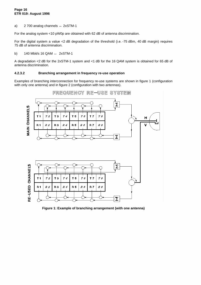
4.2.3.2 Branching arrangement in frequency re-use operation
Examples of branching interconnection for frequency re-use systems are shown in figure 1 (configurationwith only one antenna) and in figure 2 (configuration with two antennas).
Figure 1: Example of branching arrangement (with one antenna)

Page 17ETR 019: August 1996
Figure 2: Example of branching arrangement (with two antennas)
4.2.3.3 Frequency re-use system configuration
In the following figure is shown a block diagram of a typical frequency re-use system operating with aCross Polar Interference Canceller (XPIC) according with System C general description.
Figure 3: Frequency reuse system operating with an XPIC (System C)
Page 18ETR 019: August 1996
5 Remarks on performance of CCDP systems
5.1 Cross-Polar Interference Canceller (XPIC) Improvement Factor (XIF)
XIF is defined by the ratio between the C/I-threshold (for a defined BER) measured without XPIC to theC/XPI-threshold (same BER) measured with XPIC.
XIF = (C/I)th - (C/XPI)th
(C/I)th is defined as the value of the co-channel interference that generate the separation of 1 dB from theBER curve without interference.
(C/XPI)th is defined as the value of the co-channel cross-polar interference that generate the separation of1 dB from the BER curve without interference.
According with the model described as "System C", with a 32 MLCM modulation scheme, we can assume,for example, for a BER = 10-3:
- (C/I)th = 24 dB;- (C/XPI)th = 4 dB (using XPIC operation);- The XPIC Improvement Factor results: XIF = 20 dB.
Regarding the estimation of the factor (C/XPI)th, it depends on the phase-relationship between the directchannel HH (or VV) and the interference cross-polar contribution of the channel HV (or VH), according tothe model of the interfering test set described in figure 4.
In this case, we can assume that the estimation of the factor (C/XPI)th depends on a "best case" or a"worst case" in relation to the phase-position of SF4 and SF1 (or SF2 and SF3) in the described model.Consequently, we can define two values for the XIF, depending on the phase-relationship between thedirect and interference way into the interfering test set.
5.2 Antenna XPD
The measured effective cross-polar discrimination XPD0 should be at least the same as specified inETS 300 234 [17] subclause 10.1.1 for Adjacent Channel Dual Polar (ACDP) systems. That isXPD > 28 dB on typical hops, i.e. 50 km at frequencies below 11 GHz.
Remarks:
It must be noted that critical hops may require higher values of XPD.
Modern XPD-improved antennas provide XPD > 35 dB within the 1 dB contour of the pattern. Experienceshows (compare [A],[B]) that with these antennas typically XPD0+Q= 50 dB can be achieved.In connection with a (C/XPI)-threshold of 7 dB an interference fade margin of 43 dB results which isapproximately not dependent on hop length. Obviously the Interference Fade Margin (IFM) tends to behigher than typical thermal fade margins (normally below 40 dB for 50 km hop length and decreasing withincreasing length). So we can expect that frequency reuse gives rise to only marginal decrease of systemperformance.
A direct comparison between ACDP systems and CCDP systems is possible and interesting. Obviouslythe parameter "net filter discrimination (NFD)" (typical 19 dB in ACDP using 16 QAM) which is relevant inACDP systems is replaced by XIF (as seen, 20 dB in CCDP using 32MLCM) which is of the samerelevance for IFM in a CCDP-system. Due to the C/N threshold difference of about 1 dB between 16 QAMand 32MLCM, the figures NFD = 19 dB and XIF = 20 dB are equivalent in term of in-field performance.Therefore the positive experience with BER-performance gained in ACDP-systems already in use make italmost sure that CCDP systems with the parameters specified here will perform equally well.
Page 19ETR 019: August 1996
5.3 Characterisation and measurement of XPIC performance
As said before, an XPIC may be used to combat depolarization effects caused by multipath propagationand/or rain attenuation. The XPIC behaviour is proposed to be described by three characteristic values.
1. The asymptotic (or residual) XPD which is the limiting value of C/I achieved at the output of theXPIC for large values of C/I at the receiver inputs.
2. The XPD improvement factor XIF in case of flat crosstalk and co-channel fading (rain model).
3. The XPD improvement factor XIF in case of dispersive co-channel fading and dispersive crosstalk(multipath model).
The flat-fading model is just described in subclause 5.1 for the definition of the XIF parameter.
In case of multipath propagation the "flat model" is no longer applicable. An XIF value which isconservative with respect to planning calculations ca be defined and measured as follows:
In both transmission channels (HH and VV) a notch depth is adjusted to find the depth of signaturespecified for the system and used to estimate outage due to dispersive fading. The notch frequencies arevaried over the signal band and shifted parallel with the same frequency difference as compared to carrierfrequency.
In these conditions we can have a family of signature curves depending on the C/I value fixed inno-dispersive conditions.
We can define as XIF the difference between the (C/XPI)sign value (obtained for a variation of 1 dB of thelimit of the signature area ) in case of XPIC operation and the (C/I)sign value (obtained for the samevariation of the signature) in normal operation without XPIC.
According with the same 32 MLCM modulation scheme of the System C used into the considerations forthe flat-fading model (cap. 3.1), we can consider the following results:
(C/I)sign = 35 dB for a signature degradation of 1 dB at the central frequency.
(C/XPI)sign = 17 dB for a signature degradation of 1 dB at the central frequency with XPIC.
So in this case we have: XIF = (C/I)sign - (C/XPI)sign = 18 dB.
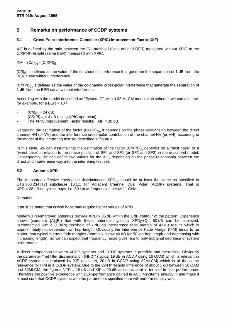
Also in this case, the results depends from the phase-relationship between the direct channel HH (or VV)and the interference cross-polar contribution of the channel HV (or VH), according with the model of theinterfering test set described in the figure below.
The following figure shows the test set for the estimation of the performances of the XPIC operation.

Page 20ETR 019: August 1996
Figure 4: XPIC performance interfering test set
Page 21ETR 019: August 1996
6 Technical parameters
6.1 Generality
This ETR specifies parameters for digital radio-relay systems with a channel capacity of 2xSTM-1designed to operate in defined bands up to 11 GHz utilising alternate or co-channel dual polarisedarrangements with about 40 MHz channel spacing.
The parameters listed fall into two categories:
a) those required to provide compatibility between channels from different sources of equipment onthe same route, connected either to separate antennas, or to separate polarizations of the sameantenna. This category also includes parameters providing compatibility with the existing radio-relaynetwork;
b) parameters defining the transmission quality of the proposed systems.
The task of defining compatibility requirements with analogue and digital systems on the same hop and atnodes is made complex by the fact that analogue systems and some digital systems are not standardised.Compatibility requirements are, therefore, limited to allowing the operation of digital and analoguechannels on separate ports of the same antenna.
The standardisation includes the following specifications:
- transmitter and receiver characteristics;- baseband and RF interface characteristics;- diversity system characteristics.
Two possible baseband interfaces have to be considered:
- one for Synchronous Transport Module-level 1 (STM-1) signals (electrical and/or optical) inaccordance with ITU-R Recommendation F. 750 [4]; and
- one for 140 Mbit/s plesiochronous signals (only electrical), according to ITU-T RecommendationG.703 [15].
The 140 Mbit/s signals should be carried "open-port", i.e. in a transparent manner independent of theircontent. They should be mapped into a 155 Mbit/s STM-1 signal as described in ITU-T RecommendationsG.708 [9] and G.709 [10].
As regards the STM-1 signal the Section Overhead (SOH) processing is covered inITU-R Recommendation F. 750 [4].
6.2 Network and system considerations
The area of application of these digital radio-relay systems is foreseen to be in regional and trunknetworks. Consideration is given to the special requirement in the case of a regional network, e.g. simplertowers with less space for antenna, different network structures with high density nodes. Application mayalso be envisaged for local links and unidirectional connections.
Systems considered in this ETR should be able to respect ITU-R high grade performance objectives.
The systems considered should operate in these networks having regard for existing hop lengths, whichare considered to be normally up to about 30 km - 40 km for regional and about 60 km for trunk networks,respectively. Hop lengths greater than this latter length, up to about 100 km, are used in specialapplications.
Page 22ETR 019: August 1996
6.3 Table of technical parameters
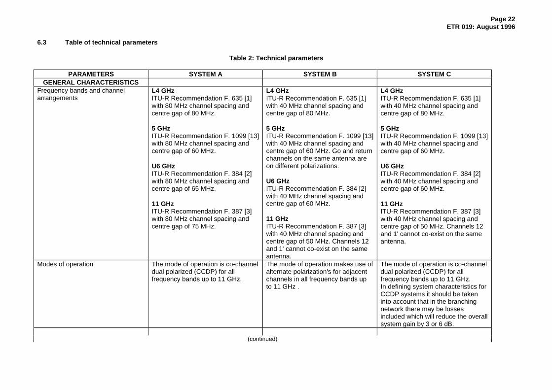
Table 2: Technical parameters
PARAMETERS SYSTEM A SYSTEM B SYSTEM CGENERAL CHARACTERISTICS
Frequency bands and channelarrangements
L4 GHzITU-R Recommendation F. 635 [1]with 80 MHz channel spacing andcentre gap of 80 MHz.
5 GHzITU-R Recommendation F. 1099 [13]with 80 MHz channel spacing andcentre gap of 60 MHz.
U6 GHzITU-R Recommendation F. 384 [2]with 80 MHz channel spacing andcentre gap of 65 MHz.
11 GHzITU-R Recommendation F. 387 [3]with 80 MHz channel spacing andcentre gap of 75 MHz.
L4 GHzITU-R Recommendation F. 635 [1]with 40 MHz channel spacing andcentre gap of 80 MHz.
5 GHzITU-R Recommendation F. 1099 [13]with 40 MHz channel spacing andcentre gap of 60 MHz. Go and returnchannels on the same antenna areon different polarizations.
U6 GHzITU-R Recommendation F. 384 [2]with 40 MHz channel spacing andcentre gap of 60 MHz.
11 GHzITU-R Recommendation F. 387 [3]with 40 MHz channel spacing andcentre gap of 50 MHz. Channels 12and 1' cannot co-exist on the sameantenna.
L4 GHzITU-R Recommendation F. 635 [1]with 40 MHz channel spacing andcentre gap of 80 MHz.
5 GHzITU-R Recommendation F. 1099 [13]with 40 MHz channel spacing andcentre gap of 60 MHz.
U6 GHzITU-R Recommendation F. 384 [2]with 40 MHz channel spacing andcentre gap of 60 MHz.
11 GHzITU-R Recommendation F. 387 [3]with 40 MHz channel spacing andcentre gap of 50 MHz. Channels 12and 1' cannot co-exist on the sameantenna.
Modes of operation The mode of operation is co-channeldual polarized (CCDP) for allfrequency bands up to 11 GHz.
The mode of operation makes use ofalternate polarization's for adjacentchannels in all frequency bands upto 11 GHz .
The mode of operation is co-channeldual polarized (CCDP) for allfrequency bands up to 11 GHz.In defining system characteristics forCCDP systems it should be takeninto account that in the branchingnetwork there may be lossesincluded which will reduce the overallsystem gain by 3 or 6 dB.
(continued)

Page 23ETR 019: August 1996
Table 2 (continued): Technical parameters
Type of installation Only indoor installations areforeseen.
Only indoor installations areforeseen.
Only indoor installations areforeseen.
Environmental condition The equipment will meet theenvironmental conditions set out inETS 300 019, Part 1-2 [6].For equipment designed forstationary use in weatherprotectedlocations (indoor installation), onlyclasses 3.1 or 3.2 apply.
The equipment will meet theenvironmental conditions set out inETS 300 019, Part 1-2 [6].For equipment designed forstationary use in weatherprotectedlocations (indoor installation), onlyclasses 3.1 or 3.2 apply.
The equipment will meet theenvironmental conditions set out inETS 300 019, Part 1-2 [6].For equipment designed forstationary use in weatherprotectedlocations (indoor installation), onlyclasses 3.1 or 3.2 apply.
Electromagnetic compatibilityconditions
Equipment is designed to operateunder the conditions specified inrelevant standards produced by theappropriate European standardorganisations (under study inETSI RES 9).For enclosure emissions andimmunity to RF electromagneticfields, the range of frequencies isextended to cover frequencies up to2 GHz.
Equipment is designed to operateunder the conditions specified inrelevant standards produced by theappropriate European standardorganisations (under study inETSI RES 9).For enclosure emissions andimmunity to RF electromagneticfields, the range of frequencies isextended to cover frequencies up to2 GHz.
Equipment is designed to operateunder the conditions specified inrelevant standards produced by theappropriate European standardorganisations (under study inETSI RES 9).For enclosure emissions andimmunity to RF electromagneticfields, the range of frequencies isextended to cover frequencies up to2 GHz.
Mechanical dimensions Slim rack version 120 mm.Height ≤ 2 200 mm
The mechanical dimensions forindoor installations are in agreementwith ETS 300 119 [16].
The mechanical dimensions forindoor installations are in agreementwith ETS 300 119 [16].
Power supply The equipment operates from any ofthe primary supplies within theranges specified in draftprETS 300 132 [7].
The equipment operates from any ofthe primary supplies within theranges specified in draftprETS 300 132 [7].
The equipment operates from any ofthe primary supplies within theranges specified in draftprETS 300 132 [7].
Safety considerations Maximum radiated power densityunder normal operating conditions isin accordance with current WorldHealth Organisation figures.
Maximum radiated power densityunder normal operating conditions isin accordance with current WorldHealth Organisation figures.
Maximum radiated power densityunder normal operating conditions isin accordance with current WorldHealth Organisation figures.
TMN interface A TMN interface will follow relevantITU-T and ITU-R Recommendationsand ETSI Standard.
A TMN interface will follow relevantITU-T and ITU-R Recommendationsand ETSI Standard.
A TMN interface will follow relevantITU-T and ITU-R Recommendationsand ETSI Standard.
(continued)

Page 24ETR 019: August 1996
Table 2 (continued): Technical parameters
System block diagram The system block diagram includingreference points is shown in figure 4.
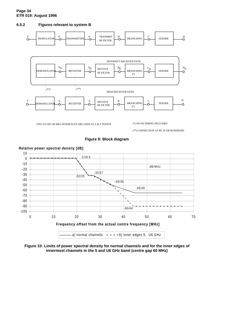
The system block diagram includingreference points is shown in figure 9.
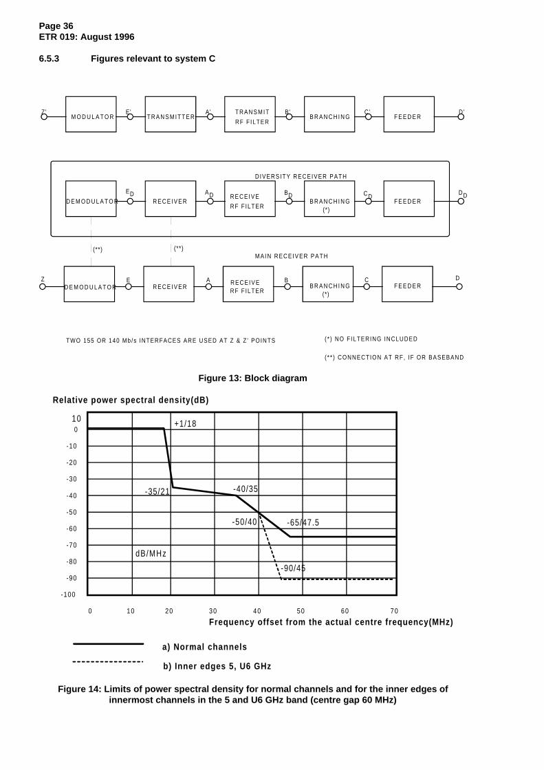
The system block diagram includingreference points is shown infigure 13.
Intermediate Frequency (IF) The If centre frequency fo is 140MHz, the subcarriers frequencies aresymmetrically arranged around 140MHz ∆f ≈ ± 17.5 MHz
If any, the IF should preferably be70 MHz.
If any, the IF should be 70 MHz or140 MHz.
Local oscillator arrangements The local oscillator frequencies forboth, transmitters and receivers, is inthe same half-band as theirassociated transmitter or receivercarrier frequencies.
The local oscillator frequencies forboth, transmitters and receivers, is inthe same half-band as theirassociated transmitter or receivercarrier frequencies.
The local oscillator frequencies forboth, transmitters and receivers, is inthe same half-band as theirassociated transmitter or receivercarrier frequencies.
TRANSMITTERCHARACTERISTICS
Output power Referred to point B' the value of theoutput power is less or equal to+38 dBm and greater or equal to+25 dBm, all tolerances included.For the purpose of systemengineering three classes of nominaloutput power are defined:Class A: +26 dBm/+31 dBmClass B: +29 dBm/+34 dBmClass C: +34 dBm/ +38 dBm
Referred to point B' the value of theoutput power is less or equal to+38 dBm and greater or equal to+25 dBm, all tolerances included.For the purpose of systemengineering three classes of nominaloutput power are defined:Class A: +26 dBm/+31 dBmClass B: +29 dBm/+34 dBmClass C: +34 dBm/ +38 dBm
Referred to point B' the value of theoutput power is less or equal to+38 dBm and greater or equal to+25 dBm, all tolerances included.For the purpose of systemengineering three classes of nominaloutput power are defined:Class A: +26 dBm/+31 dBmClass B: +29 dBm/+34 dBmClass C: +34 dBm/ +38 dBm
ATPC ATPC is an optional feature,information on ATPC is given in theinformative notes.
ATPC is an optional feature,information on ATPC is given in theinformative notes.
ATPC is an optional feature,information on ATPC is given in theinformative notes.
RF spectrum masks The spectrum mask is given in figure6 for all frequency bands considered.
The spectrum mask is given in figure10 for all frequency bandsconsidered.
The spectrum mask is given in figure14 for all frequency bandsconsidered.
Spectrum line at the symbol rate To facilitate sharing with analoguesystems the power level of spectrallines at a distance from thesubcarrier frequencies equal to thesymbol rate is less than or equal to -37 dBm.
To facilitate sharing with analoguesystems the power level of spectrallines at a distance from the channelcentre frequency equal to the symbolrate is less than or equal to -37 dBm.
To facilitate sharing with analoguesystems the power level of spectrallines at a distance from the channelcentre frequency equal to the symbolrate is less than or equal to -37 dBm.
(continued)
Page 25ETR 019: August 1996
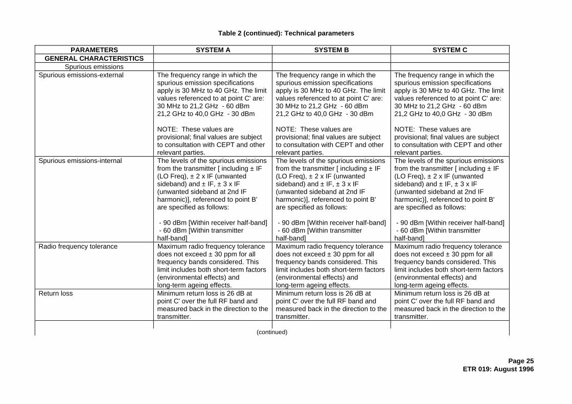
Table 2 (continued): Technical parameters
PARAMETERS SYSTEM A SYSTEM B SYSTEM CGENERAL CHARACTERISTICS
Spurious emissionsSpurious emissions-external The frequency range in which the
spurious emission specificationsapply is 30 MHz to 40 GHz. The limitvalues referenced to at point C' are:30 MHz to 21,2 GHz - 60 dBm21,2 GHz to 40,0 GHz - 30 dBm
NOTE: These values areprovisional; final values are subjectto consultation with CEPT and otherrelevant parties.
The frequency range in which thespurious emission specificationsapply is 30 MHz to 40 GHz. The limitvalues referenced to at point C' are:30 MHz to 21,2 GHz - 60 dBm21,2 GHz to 40,0 GHz - 30 dBm
NOTE: These values areprovisional; final values are subjectto consultation with CEPT and otherrelevant parties.
Spurious emissions-internal The levels of the spurious emissionsfrom the transmitter [ including ± IF(LO Freq), ± 2 x IF (unwantedsideband) and ± IF, ± 3 x IF(unwanted sideband at 2nd IFharmonic)], referenced to point B'are specified as follows:
- 90 dBm [Within receiver half-band] - 60 dBm [Within transmitterhalf-band]
The levels of the spurious emissionsfrom the transmitter [ including ± IF(LO Freq), ± 2 x IF (unwantedsideband) and ± IF, ± 3 x IF(unwanted sideband at 2nd IFharmonic)], referenced to point B'are specified as follows:
- 90 dBm [Within receiver half-band] - 60 dBm [Within transmitterhalf-band]
The levels of the spurious emissionsfrom the transmitter [ including ± IF(LO Freq), ± 2 x IF (unwantedsideband) and ± IF, ± 3 x IF(unwanted sideband at 2nd IFharmonic)], referenced to point B'are specified as follows:
- 90 dBm [Within receiver half-band] - 60 dBm [Within transmitterhalf-band]
Radio frequency tolerance Maximum radio frequency tolerancedoes not exceed ± 30 ppm for allfrequency bands considered. Thislimit includes both short-term factors(environmental effects) andlong-term ageing effects.
Maximum radio frequency tolerancedoes not exceed ± 30 ppm for allfrequency bands considered. Thislimit includes both short-term factors(environmental effects) andlong-term ageing effects.
Maximum radio frequency tolerancedoes not exceed ± 30 ppm for allfrequency bands considered. Thislimit includes both short-term factors(environmental effects) andlong-term ageing effects.
Return loss Minimum return loss is 26 dB atpoint C' over the full RF band andmeasured back in the direction to thetransmitter.
Minimum return loss is 26 dB atpoint C' over the full RF band andmeasured back in the direction to thetransmitter.
Minimum return loss is 26 dB atpoint C' over the full RF band andmeasured back in the direction to thetransmitter.
(continued)

Page 26ETR 019: August 1996
Table 2 (continued): Technical parameters
RECEIVER CHARACTERISTICSReceiver image rejection For the frequency bands as given in
the following, the receiver imagerejection is: 120 dB at L4 and 5 GHz band 100 dB at U6 GHz band
For the 11 GHz band the limit is: 90 dB.
For the frequency bands as given inthe following, the receiver imagerejection is: 95 dB at L4 and 5 GHz band 80 dB at U6 and 11 GHz band
For the frequency bands as given inthe following, the receiver imagerejection is: 120 dB at L4 and 5 GHz band 100 dB at U6 GHz band
For the 11 GHz band the limit is: 90 dB.
Spurious emissionsSpurious emissions-external The frequency range in which the
spurious emission specificationsapply is 30 MHz to 40 GHz. The limitvalues measured at point C are:30 MHz to 21,2 GHz - 60 dBm21,2 GHz to 40,0 GHz - 30 dBm
NOTE: These values areprovisional; final values are subjectto consultation with CEPT and otherrelevant parties.
The frequency range in which thespurious emission specificationsapply is 30 MHz to 40 GHz. The limitvalues measured at point C are:30 MHz to 21,2 GHz - 60 dBm21,2 GHz to 40,0 GHz - 30 dBm
NOTE: These values areprovisional; final values are subjectto consultation with CEPT and otherrelevant parties.
The frequency range in which thespurious emission specificationsapply is 30 MHz to 40 GHz. The limitvalues measured at point C are:30 MHz to 21,2 GHz - 60 dBm21,2 GHz to 40,0 GHz - 30 dBm
NOTE: These values areprovisional; final values are subjectto consultation with CEPT and otherrelevant parties.
Spurious emissions-internal For spurious emissions at the localoscillator frequency a provisionallimit of < - 110 dBm for all bandsapplies (referenced to point B).
For spurious emissions at the localoscillator frequency a provisionallimit of < - 110 dBm for all bandsapplies (referenced to point B).
For spurious emissions at the localoscillator frequency a provisionallimit of < - 110 dBm for all bandsapplies (referenced to point B).
Input level range The lower limit for the receiver inputlevel is given by the threshold levelfor Bit Error Ratio (BER) = 10-3. Theupper limit for the receiver inputlevel, where a BER of 10-3 is notexceeded is -17 dBm; a BER of10-10 may only be exceeded forlevels greater than -21 dBm. Theselimits apply without "external"interference and are referenced topoint B.
The lower limit for the receiver inputlevel is given by the threshold levelfor Bit Error Ratio (BER) = 10-3. Theupper limit for the receiver inputlevel, where a BER of 10-3 is notexceeded is -17 dBm; a BER of10-10 may only be exceeded forlevels greater than -21 dBm. Theselimits apply without interference andare referenced to point B.
The lower limit for the receiver inputlevel is given by the threshold levelfor Bit Error Ratio (BER) = 10-3. Theupper limit for the receiver inputlevel, where a BER of 10-3 is notexceeded is -17 dBm; a BER of10-10 may only be exceeded forlevels greater than -21 dBm. Theselimits apply without "external"interference and are referenced topoint B.
(continued)
Page 27ETR 019: August 1996
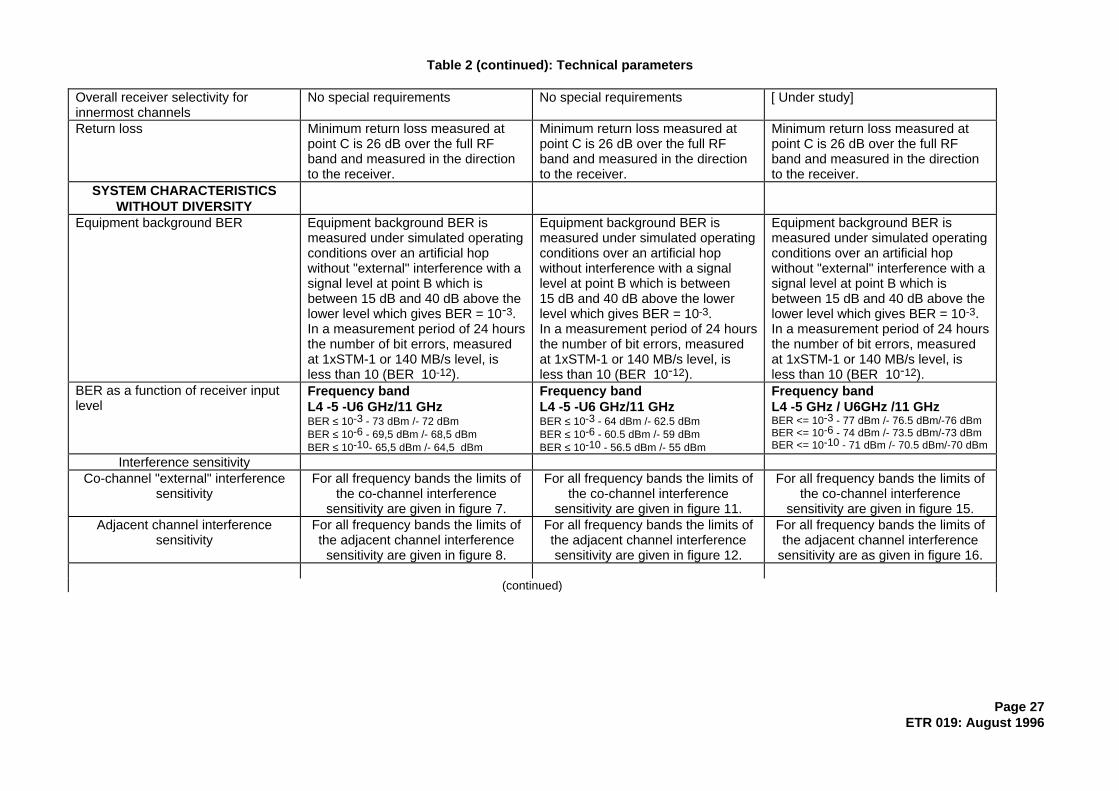
Table 2 (continued): Technical parameters
Overall receiver selectivity forinnermost channels
No special requirements No special requirements [ Under study]
Return loss Minimum return loss measured atpoint C is 26 dB over the full RFband and measured in the directionto the receiver.
Minimum return loss measured atpoint C is 26 dB over the full RFband and measured in the directionto the receiver.
Minimum return loss measured atpoint C is 26 dB over the full RFband and measured in the directionto the receiver.
SYSTEM CHARACTERISTICSWITHOUT DIVERSITY
Equipment background BER Equipment background BER ismeasured under simulated operatingconditions over an artificial hopwithout "external" interference with asignal level at point B which isbetween 15 dB and 40 dB above thelower level which gives BER = 10-3.In a measurement period of 24 hoursthe number of bit errors, measuredat 1xSTM-1 or 140 MB/s level, isless than 10 (BER 10-12).
Equipment background BER ismeasured under simulated operatingconditions over an artificial hopwithout interference with a signallevel at point B which is between15 dB and 40 dB above the lowerlevel which gives BER = 10-3.In a measurement period of 24 hoursthe number of bit errors, measuredat 1xSTM-1 or 140 MB/s level, isless than 10 (BER 10-12).
Equipment background BER ismeasured under simulated operatingconditions over an artificial hopwithout "external" interference with asignal level at point B which isbetween 15 dB and 40 dB above thelower level which gives BER = 10-3.In a measurement period of 24 hoursthe number of bit errors, measuredat 1xSTM-1 or 140 MB/s level, isless than 10 (BER 10-12).
BER as a function of receiver inputlevel
Frequency bandL4 -5 -U6 GHz/11 GHzBER ≤ 10-3 - 73 dBm /- 72 dBmBER ≤ 10-6 - 69,5 dBm /- 68,5 dBmBER ≤ 10-10- 65,5 dBm /- 64,5 dBm
Frequency bandL4 -5 -U6 GHz/11 GHzBER ≤ 10-3 - 64 dBm /- 62.5 dBmBER ≤ 10-6 - 60.5 dBm /- 59 dBmBER ≤ 10-10 - 56.5 dBm /- 55 dBm
Frequency bandL4 -5 GHz / U6GHz /11 GHzBER <= 10-3 - 77 dBm /- 76.5 dBm/-76 dBmBER <= 10-6 - 74 dBm /- 73.5 dBm/-73 dBmBER <= 10-10 - 71 dBm /- 70.5 dBm/-70 dBm
Interference sensitivityCo-channel "external" interference
sensitivityFor all frequency bands the limits of
the co-channel interferencesensitivity are given in figure 7.
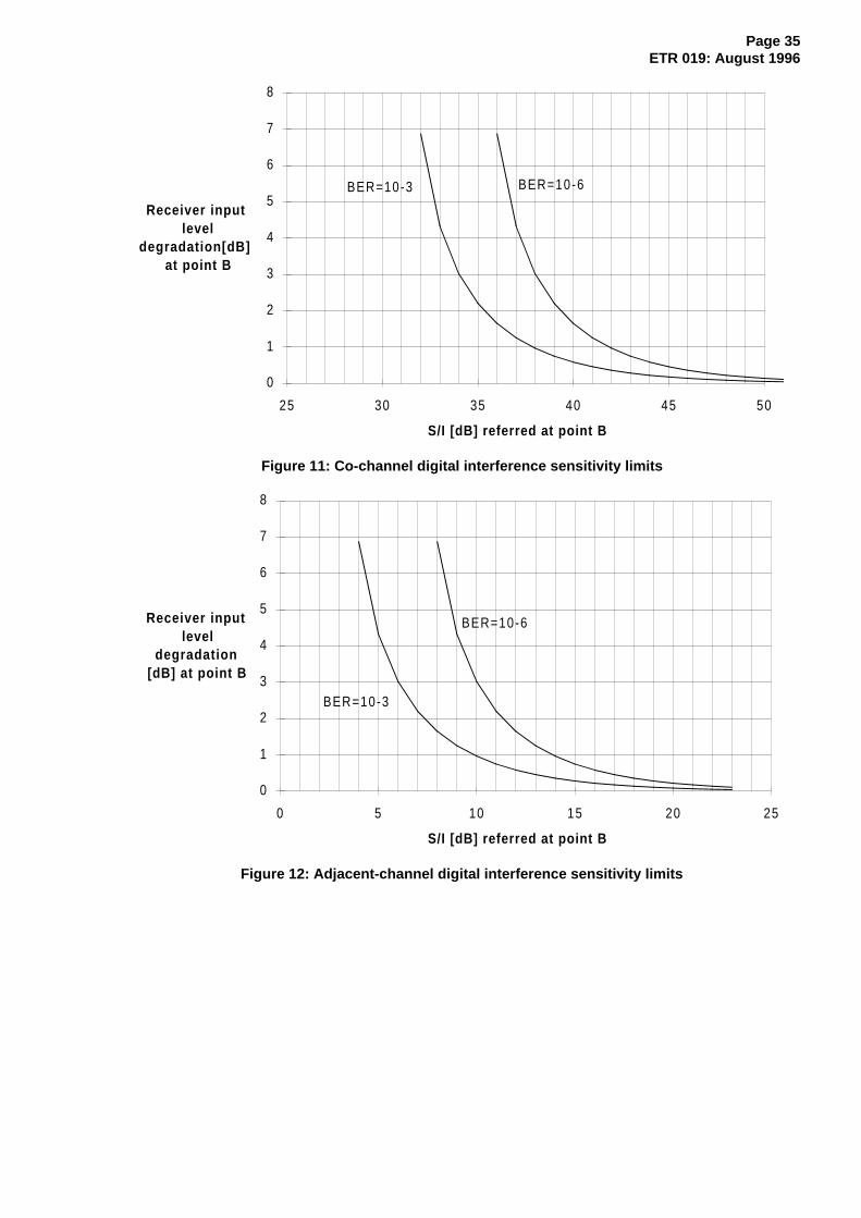
For all frequency bands the limits ofthe co-channel interference
sensitivity are given in figure 11.
For all frequency bands the limits ofthe co-channel interference
sensitivity are given in figure 15.Adjacent channel interference
sensitivityFor all frequency bands the limits ofthe adjacent channel interference
sensitivity are given in figure 8.
For all frequency bands the limits ofthe adjacent channel interferencesensitivity are given in figure 12.
For all frequency bands the limits ofthe adjacent channel interference
sensitivity are as given in figure 16.
(continued)
Page 28ETR 019: August 1996
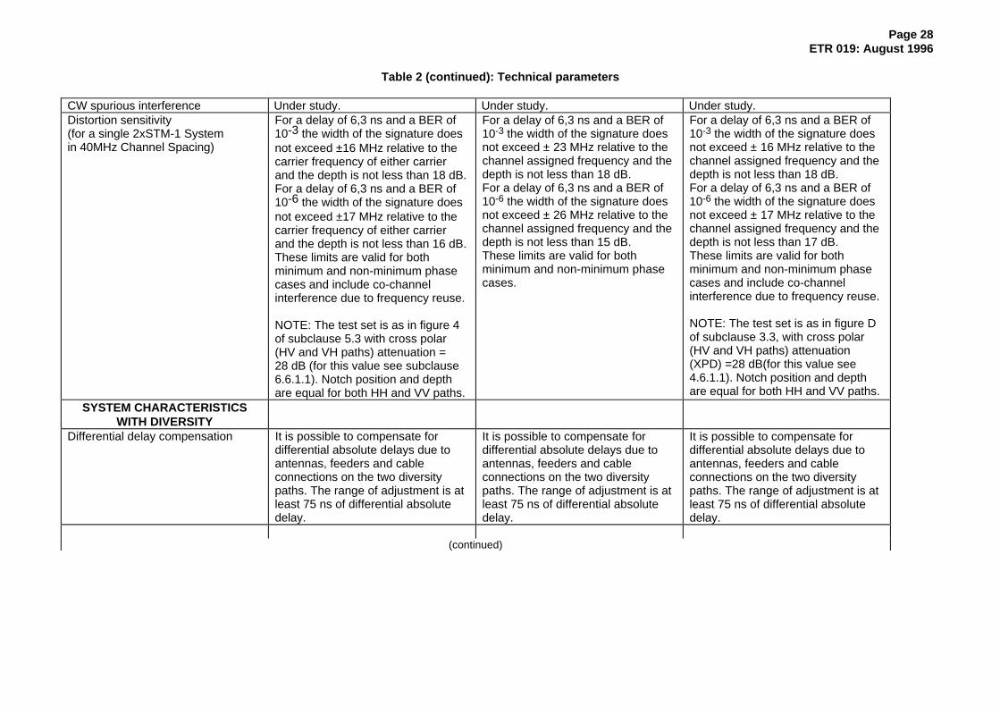
Table 2 (continued): Technical parameters
CW spurious interference Under study. Under study. Under study.Distortion sensitivity(for a single 2xSTM-1 Systemin 40MHz Channel Spacing)
For a delay of 6,3 ns and a BER of10-3 the width of the signature doesnot exceed ±16 MHz relative to thecarrier frequency of either carrierand the depth is not less than 18 dB.For a delay of 6,3 ns and a BER of10-6 the width of the signature doesnot exceed ±17 MHz relative to thecarrier frequency of either carrierand the depth is not less than 16 dB.These limits are valid for bothminimum and non-minimum phasecases and include co-channelinterference due to frequency reuse.
NOTE: The test set is as in figure 4of subclause 5.3 with cross polar(HV and VH paths) attenuation =28 dB (for this value see subclause6.6.1.1). Notch position and depthare equal for both HH and VV paths.
For a delay of 6,3 ns and a BER of10-3 the width of the signature doesnot exceed ± 23 MHz relative to thechannel assigned frequency and thedepth is not less than 18 dB.For a delay of 6,3 ns and a BER of10-6 the width of the signature doesnot exceed ± 26 MHz relative to thechannel assigned frequency and thedepth is not less than 15 dB.These limits are valid for bothminimum and non-minimum phasecases.
For a delay of 6,3 ns and a BER of10-3 the width of the signature doesnot exceed ± 16 MHz relative to thechannel assigned frequency and thedepth is not less than 18 dB.For a delay of 6,3 ns and a BER of10-6 the width of the signature doesnot exceed ± 17 MHz relative to thechannel assigned frequency and thedepth is not less than 17 dB.These limits are valid for bothminimum and non-minimum phasecases and include co-channelinterference due to frequency reuse.
NOTE: The test set is as in figure Dof subclause 3.3, with cross polar(HV and VH paths) attenuation(XPD) =28 dB(for this value see4.6.1.1). Notch position and depthare equal for both HH and VV paths.
SYSTEM CHARACTERISTICSWITH DIVERSITY
Differential delay compensation It is possible to compensate fordifferential absolute delays due toantennas, feeders and cableconnections on the two diversitypaths. The range of adjustment is atleast 75 ns of differential absolutedelay.
It is possible to compensate fordifferential absolute delays due toantennas, feeders and cableconnections on the two diversitypaths. The range of adjustment is atleast 75 ns of differential absolutedelay.
It is possible to compensate fordifferential absolute delays due toantennas, feeders and cableconnections on the two diversitypaths. The range of adjustment is atleast 75 ns of differential absolutedelay.
(continued)
Page 29ETR 019: August 1996
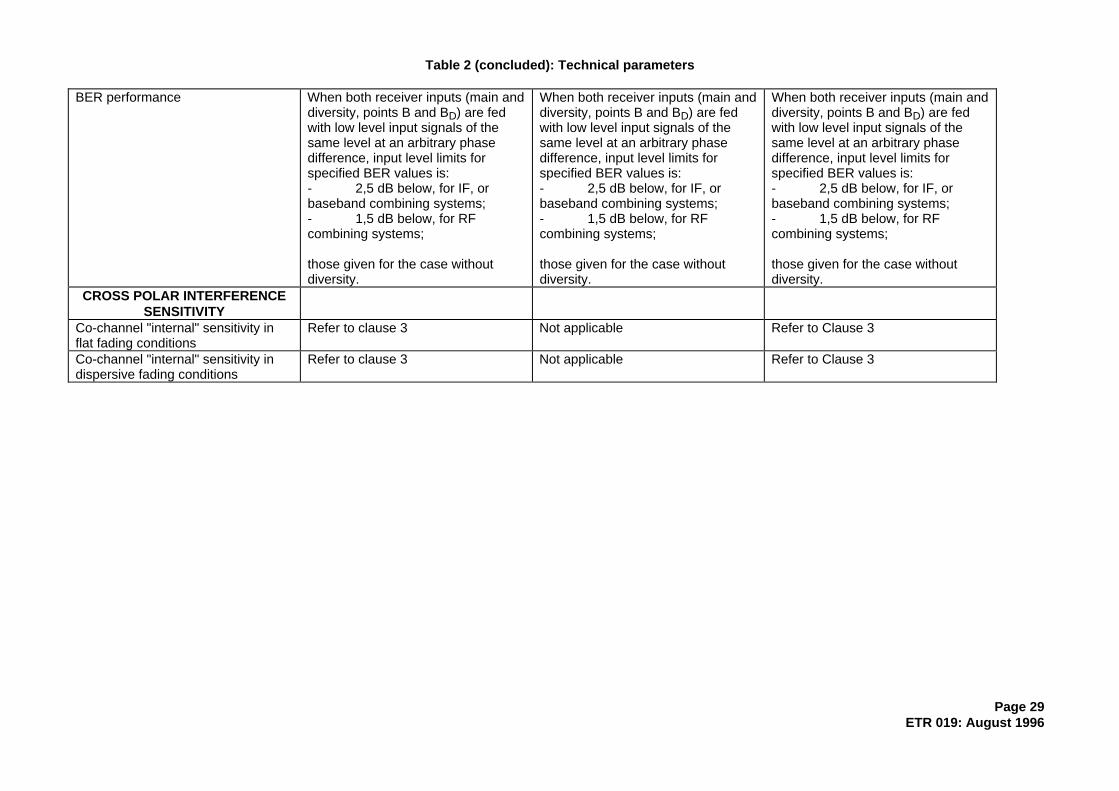
Table 2 (concluded): Technical parameters
BER performance When both receiver inputs (main anddiversity, points B and BD) are fedwith low level input signals of thesame level at an arbitrary phasedifference, input level limits forspecified BER values is:- 2,5 dB below, for IF, orbaseband combining systems;- 1,5 dB below, for RFcombining systems;
those given for the case withoutdiversity.
When both receiver inputs (main anddiversity, points B and BD) are fedwith low level input signals of thesame level at an arbitrary phasedifference, input level limits forspecified BER values is:- 2,5 dB below, for IF, orbaseband combining systems;- 1,5 dB below, for RFcombining systems;
those given for the case withoutdiversity.
CROSS POLAR INTERFERENCESENSITIVITY
Co-channel "internal" sensitivity inflat fading conditions
Refer to clause 3 Not applicable Refer to Clause 3
Co-channel "internal" sensitivity indispersive fading conditions
Refer to clause 3 Not applicable Refer to Clause 3
Page 30ETR 019: August 1996
6.4 Informative notes
6.4.1 Branching/feeder/antenna requirements
The parameters and values specified below are essential prerequisites for the system specification givenin this ETR.
6.4.1.1 Cross Polar Discrimination (XPD)
The measured effective XPD over a typical hop under no-fading conditions should not be less than 28 dB.
6.4.1.2 Intermodulation products
Each intermodulation product caused by different transmitters linked to the same antenna is less than- 110 dBm referenced to point B with an output power of about 28 dBm per transmitter.
6.4.1.3 Interport isolation
This should not be less than 40 dB.
6.4.1.4 Return loss
This should not be less than 26 dB (Voltage Standing Wave Ratio (VSWR) = 1.10:1) at the antenna flange(points D, D').
6.4.2 Automatic Transmit Power Control (ATPC)
ATPC can be useful in many circumstances, especially:
- to improve analogue-digital compatibility in the case of antennas with poor cross-polarizationdiscrimination performance or in the case of high nominal output power for the Digital Radio RelaySystems (DRRS);
- to reduce digital to digital distant interference between hops which re-use the same frequency;
- to improve compatibility with both digital and analog systems at nodal stations;
- to reduce the effects of up-fading propagation conditions on the system.
ATPC is an optional feature which is aimed at driving the Transmit (TX) power amplifier output level froma proper minimum which is calculated to facilitate the radio network planning and which is used in thecase of normal propagation up to a maximum value which is defined by the relative class of output powerand the complete fulfilment of all the specifications defined in this ETR.
The ATPC range is the power interval from the nominal output power level to the lowest power amplifieroutput level (at point B') with ATPC.
The ATPC range should not exceed 25 dB. When compatibility with analogue systems is required, thelowest power amplifier output level should not be less than + 10 dBm; this may result in a reduced ATPCrange.

Page 31ETR 019: August 1996
6.5 Figures
6.5.1 Figures relevant to system A
MODULATOR TRANSMITTERZ' E' A' TRANSMIT
RF FILTER
B'BRANCHING
C' D'FEEDER
FEEDER
FEEDER
BRANCHING
BRANCHING
RF FILTER
RF FILTER
RECEIVERRECEIVE
DEMODULATOR
ED AD DB
(*)
CDDD
D
(*)
CBRECEIVEARECEIVER
(**)(**)
EDEMODULATOR
Z
MAIN RECEIVER PATH
DIVERSITY RECEIVER PATH
TWO 155 OR 140 Mb/s INTERFACES ARE USED AT Z & Z' POINTS (*) NO FILTERING INCLUDED
(**) CONNECTION AT RF, IF OR BASEBAND
Figure 5: Block diagram

Page 32ETR 019: August 1996
-30
-40
-70
0
-10
-20
-50
-60
-80
+1
-90
-100
-110
200 4010 30 60 70 80 90 100 110 120 130 14050
+ 1/35
-45/40
-65/50
-120/80
-125/140
-90/80
dB /MHz
norm al channel
innerm ost channel
-120
-130
Relative power spectral density (dB)
Frequency offset from the actual centre frequency (MHz)
NOTE: The mask does not include the frequency tolerance
Figure 6: Limits of power spectral density for normal channels and for the inner edges ofinnermost channels referred to point B'

Page 33ETR 019: August 1996
BER 10E-6
BER 10E-3
0
2
6
8
4
21 23 25 27 29 31 33 35 37
Receiver input level degradation (dB)
Signal to interference ratio (dB)
Figure 7: Co-channel "external" digital interference sensitivity limits referred to point B'
Signal to interference ratio (dB)
BER 10E-6
BER 10E-3
0
2
6
8
4
-44 -42 -40 -38 -36 -34 -32 -30 -28
Receiver input level degradation (dB)
Figure 8: Adjacent-channel digital interference sensitivity limits referred to point B'
Page 34ETR 019: August 1996
6.5.2 Figures relevant to system B
MODULATOR TRANSMITTERZ' E' A' TRANSMIT
RF FILTER
B'BRANCHING
C' D'FEEDER
FEEDER
FEEDER
BRANCHING
BRANCHING
RF FILTER
RF FILTER
RECEIVERRECEIVE
DEMODULATOR
ED AD DB
(*)
CDDD
D
(*)
CBRECEIVEARECEIVER
(**)(**)
EDEMODULATOR
Z
MAIN RECEIVER PATH
DIVERSITY RECEIVER PATH
TWO 155 OR 140 Mb/s INTERFACES ARE USED AT Z & Z' POINTS (*) NO FILTERING INCLUDED
(**) CONNECTION AT RF, IF OR BASEBAND
Figure 9: Block diagram
-100-90-80
-70-60-50-40-30-20
-100
10
0 10 20 30 40 50 60 70
Frequency offset from the actual centre frequency [MHz]
a) normal channels b) inner edges 5, U6 GHz
1/19.5
-32/25-32/27
-50/35
-65/45
-90/44
dB/MHz
Relative power spectral density [dB]
Figure 10: Limits of power spectral density for normal channels and for the inner edges ofinnermost channels in the 5 and U6 GHz band (centre gap 60 MHz)
Page 35ETR 019: August 1996
S/I [dB] referred at point B
Receiver inputlevel
degradation[dB]at point B
0
1
2
3
4
5
6
7
8
25 30 35 40 45 50
BER=10-3 BER=10-6
Figure 11: Co-channel digital interference sensitivity limits
S/I [dB] referred at point B
Receiver inputlevel
degradation[dB] at point B
0
1
2
3
4
5
6
7
8
0 5 10 15 20 25
BER=10-3
BER=10-6
Figure 12: Adjacent-channel digital interference sensitivity limits
Page 36ETR 019: August 1996
6.5.3 Figures relevant to system C
M O D U L A T O R T R A N S M I T T E RZ' E' A' T R A N S M I T
RF F ILTER
B'B R A N C H I N G
C' D'F E E D E R
F E E D E R
F E E D E R
B R A N C H I N G
B R A N C H I N G
RF F ILTER
RF F ILTER
R E C E I V E RR E C E I V E
D E M O D U L A T O R
ED AD DB
(*)
CDDD
D
(*)
CBR E C E I V EAR E C E I V E R
(**)(**)
ED E M O D U L A T O R
Z
M A I N R E C E I V E R P A T H
D I V E R S I T Y R E C E I V E R P A T H
TWO 155 OR 140 Mb/s INTERFACES ARE USED AT Z & Z ' POINTS ( * ) NO F ILTERING INCLUDED
(* * ) CONNECTION AT RF , IF OR BASEBAND
Figure 13: Block diagram
10 0
-10
-20
-30
-40
-50
-60
-70
-80
-90
-100
0 10 20 30 40 50 60 70
Relative power spectral density(dB)
Frequency offset from the actual centre frequency(MHz)
a) Normal channels
b) Inner edges 5, U6 GHz
+1/18
-35/21 -40/35
-50/40 -65/47.5
-90/45
dB/MHz
Figure 14: Limits of power spectral density for normal channels and for the inner edges ofinnermost channels in the 5 and U6 GHz band (centre gap 60 MHz)

Page 37ETR 019: August 1996
Received input level(dB)
S/I (dB)Reference point B 19 21 23 25 27 29 31
XX
XX+2
XX+4
XX+6
XX+8
BER 10E-6
BER 10E-3
XX = -77,0 dBm for L4 and 5 G Hz System s
XX = -76,5 dBm for U6 G Hz System
XX = -76,0 dBm for 11 G H z System
Figure 15: Co-channel "external" digital interference sensitivity limits
Received input level(dB)
S/I (dB)Reference point B -21 -19 -17 -15 -13 -11 -9
XX
XX+2
XX+4
XX+6
XX+8
BER 10E-6
BER 10E-3
XX = -77,0 dBm for L4 and 5 G H z System s
XX = -76,5 dBm for U 6 G H z System
XX = -76 ,0 dBm for 11 G Hz System
Figure 16: Adjacent-channel digital interference sensitivity limits

Page 38ETR 019: August 1996
Annex A: Bibliography
- M. Glauner, M. Biester, "Performance of co-channel dual polarized systems with modern antennadesign. Influence antenna XPD and XPIC improvement factor", 1993 SBMO InternationalMicrowave Conf./BRAZIL, Sao Paulo, August 2-5, VOL I, pp 167-172
- K. Vogel, K.J. Friederichs, "The benefit of cross-polar co-channel operation in digital radionetworks", 4th ECRR, Edinburgh, UK, Oct. 11-14, 1993, pp 167-174
- P. Balducci, M. Bolla, L. Rossi, A. Spalvieri, "A new 32 QAM modem for doubling transmissioncapacity in 40 MHz channelling plans", GLOBECOM '92 - Sect. 53.2
- M. Biester, E. Douverne, U. Hulsen, K. Ruthemann, W. Zimmer, "Hardware realization of an XPICsystem / Measurement method and results", Fourth European Conference on Radio RelaySystems. Oct. '93. Edinburgh.
Page 39ETR 019: August 1996
History
Document history
March 1991 First Edition
August 1996 Second Edition
ISBN 2-7437-0829-8Dépôt légal : Août 1996