ethisalat ftth design guide
TRANSCRIPT
8/18/2019 Ethisalat FTTH Design Guide
http://slidepdf.com/reader/full/ethisalat-ftth-design-guide 1/51
Design Guide For Fibre-To-The-Home (FTTH)
Requirements in New Buildings
January 2013
www.etisalat.ae/FTTHguides

8/18/2019 Ethisalat FTTH Design Guide
http://slidepdf.com/reader/full/ethisalat-ftth-design-guide 2/51
Table of contents
Introduction 2
General telecom requirements 3
Civil requirements applicable for all types of buildings 3
Entry box 3
Entry pipes 3Main telecom room 4
Floor telecom space 5
Roof-top telecom room 5
Risers from main telecom room to individual floors 6
Floor distribution box 6
Indoor equipment cabinet 7
Flat distribution 7
Villa distribution 8
Structure Identification Plate 8
Mobile requirements 8
FTTH Requirements 9
Fiber distribution hub at main telecom room 9
Fibre optic cable 9

8/18/2019 Ethisalat FTTH Design Guide
http://slidepdf.com/reader/full/ethisalat-ftth-design-guide 3/51
Fibre optic cables in buildings 9Fibre optic cables in single villas & complex villas 10
Fibre optic cable in mobile service rooms 10
Micro ODF 10
Etisalat telecom requirements 11
Etisalat telecom requirements - Table 1 11
Structured Cabling System (SCS) 15
Cabling & termination 15
Telecommunication cabling 15
Telecommunication socket 15
Accessories 16
Horizontal subsystem (UTP Cables) 16
Labeling 19
Under-floor systems 19
Main elements of under-floor raceway systems 19
Protection from electromagnetic interference 20
Private Branch Exchange (PBX) 21
Important notes 23
List of annexures 26

8/18/2019 Ethisalat FTTH Design Guide
http://slidepdf.com/reader/full/ethisalat-ftth-design-guide 4/51
1

8/18/2019 Ethisalat FTTH Design Guide
http://slidepdf.com/reader/full/ethisalat-ftth-design-guide 5/51
Introduction
Telecommunication is now an integral part of social,economic and political issues of the world. Networks ofthe future will be digital and intelligent and will offerhigh transmission capacity and flexible bandwidth; inaddition, they will be easily accessed and connected
while its services will be personal and tailored toindividual needs. These will allow us to interact in wayspreviously not possible - available at any time andany place. In addition to providing entertainment andbusiness services, networks of the future will provideeducation, health and other public services.
Major advances in communications technology havesubstantially widened the range of services carried
by the network. Satellites, microwave radio, opticalcable links, digital switching and transmission, offer apotential for the improvement of quality and for theextension of access to the most remote areas. Thepace of technological change is increasing while themagnitude of demands the future will make on ourcreativity and capacity to adapt is great. Customers willdemand more than just state of-the-art technology;
they will want convenience and increased controlin their lives that affordable information accesscan provide. While businesses will look for totaltelecommunications solutions that will not only enablethem to remain productive and compete globally butwill also give them a competitive edge.
Etisalat can be well-placed to meet these challengesahead and meet the varied needs of our local andinternational customers and pave the way for the region’snew dynamism in the telecommunications industry wellinto the 21st century.
As technology and mode of transport are changingfast, a broad approach to suit all future type ofservices will have to be borne in mind, while designingthe infrastructures for buildings. A properly designedbuilding with clear Access
Path supports the triple play services, viz telephony,data and video services. Also, supports future advanced
services, warranting higher speeds and higherbandwidth, planned to be available in near future, forfaster provision of services.
The present booklet is to provide guidelines forconsultants, contractors and the details on the in-building facilities required to be considered at thedesign stage. The details provided are a general insight
and the minimum requirements of Etisalat for the newbuildings, primarily to develop and deploy FTTH (Fibreto the Home), based on GPON technology.
2

8/18/2019 Ethisalat FTTH Design Guide
http://slidepdf.com/reader/full/ethisalat-ftth-design-guide 6/51
General telecom requirementsTo provide telecom services, the internal concealed pipe and other associated requirements vary for the different
building types. The various types of buildings are grouped as commercial buildings, residential towers, warehouses, medium high-rise buildings, shopping complexes, retail houses, row houses, independent villas, campusvillas, labour camps, mosques, petrol pumps, etc.
The building owners, builders, property developers, consultants and contractors are advised to provide the variousin–building requirements, as applicable, to ensure timely provision of services.
Civil requirements applicable for all types of buildings
Entry boxEntry box is an underground joint box built, exclusively to allow installation of Etisalat underground cable networkto the customer’s premises.• The entry box is a reinforced concrete structure, with a heavy duty Ductile Iron Frame and Cover of rating
grade ‘A’ and size is 600mm X 600mm X 800mm. The cover shall have marking as “Telephones”
• The location of the entry box depends on the location of existing/proposed Etisalat external line plant
• The entry box should be constructed at a maximum distance of 1 meter from plot line. Make sure it touchesthe boundary wall. However, if such provision is not feasible due to site conditions, Etisalat must be consultedfor further advice
• The entry box should be exclusive for Etisalat use and no other services shall be allowed to use the same
• Due to the variables involved, it is essential to consult Etisalat at the design stage, to decide the location ofthe entry box and entry pipe. The consultants/contractors must not deviate from the stipulated location
• An earth rod must be provided at the entry box. The required earth resistance should not exceed more than5 ohms
• For entry box size details please refer to Table No. 1
Entry pipes (Lead-in ducts)The entry pipes are uPVC ducts. These ducts are to be extended from the entry box towards premises and towards
Etisalat line plant location.• Entry pipes should be laid at a depth of 600mm from the proposed nished paving level. The entry pipe mustbe protected with concrete to prevent damages, especially at points where pipes cross with other services
3

8/18/2019 Ethisalat FTTH Design Guide
http://slidepdf.com/reader/full/ethisalat-ftth-design-guide 7/51
• Entry pipe should be extended to the entry box and beyond to the nearestexisting Etisalat plant location, or 1meter from plot limit or as advisedby Etisalat
• The entry pipe should be of uPVC material and of black color• The open ends of the entry pipe must be properly sealed, to prevent entry of sub-soil
materials and ingress of water
• Location of entry pipes must be clearly marked, above ground especially pipe ends outsidethe plot for easy location
• Building contractors shall be responsible to locate the installed entry pipes on site, ifrequested by Etisalat
• No right-angled sharp bends should be installed throughout the duct length, exceptone wide-angle, long radius bend (factory made) at the terminating end of the duct,inside the main telecom room. Alternatively, at the location of the wide angle bend, a cable pull boxof minimum size 600mm (L) X 600mm (W) X 800mm (D) must be provided
• Entry pipes must be assigned, exclusively for Etisalat telecommunication services
• Entry pipes must be provided with a draw rope made of nylon of minimum 6mm diameter
• For the number and size of entry pipes, for the various types of buildings, please refer to Table 1
Main telecom roomMain telecom room should be a dedicated room. This is to be provided either on the ground floor or basement ofthe building for the purpose of terminating telecommunication cables and to house the present & future telecomequipment. If in any case, the main telephone room will be in different floors other than recommended Etisalatmust be consulted. The room must be reserved exclusively for Etisalat use.
• The room must be easily accessible to Etisalat Personnel 24 hr./day, (all days including weekends). The room
must be clean, dry and free from dust and secured from unauthorized entry.• The room location must not be beneath or next to kitchens, washrooms, garbage areas, swimming pools and
other wet areas.
• Adequate lighting and minimum of four 20 amp. and 240 volt A.C. Mains outlet from a dedicated circuitbreaker should be provided.
• The room must be air-conditioned.
• A “raised oor” of minimum 300mm should be provided if required, depending on the telecom room usage.
• The room must be provided with a good earth set with resistance of less than 1 ohms.• The door opening for the room should swing outwards.
4

8/18/2019 Ethisalat FTTH Design Guide
http://slidepdf.com/reader/full/ethisalat-ftth-design-guide 8/51
• The oor, roof and surrounding wall of the telecom room, should be free of any concealed water/drainagepipes and air-conditioning ducts passing through.
• The room must be provided with an emergency light, a smoke detector and a re alarm including two hand
held CO2 fire extinguishers of minimum 10KG capacity.• If the telecom room is proposed in the basement, an automatic sump draining system must be provided to
handle water seepages.
• The duct entry to building must be sealed air and water tight.
• For the main telecom room size, please refer Table No. 1
Floor telecom space
Floor telecom space is a dedicated area, and required on each oor for the purpose of routing and/or terminatingtelecommunication cables, and it should be exclusively for Etisalat use.
• The room must readily be accessible to Etisalat personnel and equipment 24 hr./day, all the days, round theclock and it must be clean, dry, free from dust and secured from unauthorized entry.
• The door opening for the room should swing outwards, when opened.
• For the oor telecom space, please refer Table No. 1
Roof-top telecom roomRoof-top telecom room is a dedicated room to be provided on the roof-top of the proposed multi-storey buildings,exclusively for Etisalat use and secured from unauthorized entry. The minimum roof-top telecom room sizeshould be 3m (L) X 3m (W) X 3m (H).
• The oor loading of this area must be maximum possible, to support future installation of
telecommunications equipment
• An opening of size 600mm X 400mm to be provided on the wall of the room, facing the terrace, 500mm below
the room ceiling
• The location of the room should be within the vertical structure of the building, with due considerationsfor load safety provisions and to extend related facilities required such as air-conditioning, 3-phase powerDistribution Board (DB), earthing less than 1 ohms, adequate lighting, two 13 amp. 240V AC power socket andone telephone socket
• The room must be provided with an emergency light, a smoke detector and afire alarm
• The room must be free from any water pipes to prevent equipment damage in case of water leakage• The room must readily be accessible to Etisalat personnel and equipment 24 hr every day, all the days, round
the clock and the room must be clean, dry and free from dust5

8/18/2019 Ethisalat FTTH Design Guide
http://slidepdf.com/reader/full/ethisalat-ftth-design-guide 9/51
Risers from main telecom room to individual oorsThe risers are required in multiple-storey buildings for the installation of fibre optic cables from main telecomroom to other floors, as detailed below:
• Galvanized slotted iron cable trays minimum 200mm X 50mm Heavy Duty, Return Flange (HDRF) should beprovided from the main telephone room, to each typical floor telecom room and extended up to the roof-toptelecom room.
• The risers to each oor must be symmetrical and vertically in line with the main telecom room. However,where the main telecom room, floor telecom space and roof-top telecom room are to be located one belowthe other in vertical line, a continuous cable tray must be provided up to the main telecom room.
• If a building consists of more than one tower, all the above specied requirements are required in each tower.
The towers must be inter-connected at the main telecom room, by separate cable trays of minimum 2 nos. andsize 200mm X 50mm or through floor raceways passing through a common area between the two buildings.
The size of the floor raceways is to be decided at the design stage by Etisalat. The same requirements alsoapply to mezzanine and penthouse floors. The telecom cable trays should have adequate separation fromelectrical cable trays. Electrical cable trays should not cross the telecom cable trays.
Floor distribution box
Floor distribution boxes are either PVC made or metallic boxes, concealed, located on the wall, where the internalconduit from every flat is terminated. These empty boxes should be located close to the risers and can be morethan one, depending upon the number of flats and conduits proposed to be terminated. These distribution boxesfacilitate to route the fibre optic cables to the premises directly and where the number of cables corresponds tothe number of at/premises.
However, floor distribution box may not be required for cases where horizontal distributionleading to each at/premises is through cable tray.
• The distribution boxes should be of size not less than 300mm (L) X 300mm (H) X150mm (D) flush mounted on wall. A suitable hinged cover must be provided
• It should be installed at a height of 600mm to 1200mm from nished oor level
• Adequate safe working space is to be provided around each location
• The distribution boxes on a oor, should not be linked to or serve anyother floor of the building
• The distribution boxes location should never be near any electrical
junction box or bus bars
6

8/18/2019 Ethisalat FTTH Design Guide
http://slidepdf.com/reader/full/ethisalat-ftth-design-guide 10/51
• A single conduit of at least 25mm (1 inch) internal diameter, black and of uPVC material should be providedfrom each floor distribution box up to the indoor equipment cabinet of each office, residence, flat and otherindependent areas in the same floor
• Etisalat should be consulted to enhance the requirements, if the building is designed for commercial use
Indoor equipment cabinetIndoor equipment cabinet must be provided in each flat, villa or office and must be installed in a secured place.The cabinet specified will house Optical Network Units (ONU) & its accessories and must be located as per thefollowing conditions.
• The cabinet should be at a common point where all internal conduits meet in support of SCS on a star topology
• The cabinet should be in central and accessible locations and shall house the following• RJ45 patch panel/IDC modules
• Micro ODF for bre termination
• Power sockets
• Should have sufcient space around the cabinet to allow access to installation and maintenance
• The cabinet should be installed at a height of 1200mm above nished oor level for better working positionand to prevent accidental access by children
• Should be located where the farthest telecom socket must not exceed 90 meters from the indoor equipment cabinet
• Should be installed in an air-conditioned environment.
• Should not be installed adjacent to any electrical distribution or bus bars.
• Should not be installed in the kitchen or near to washroom and other wet areas.
Details and specification of indoor equipment cabinet in residential and commercial buildings are provided inAnnexure 3.
Flat distributionAll UTP cables inside the flat must be through a PVC conduit from indoor equipment cabinet to individualtelecom socket.
• Internal conduit must run from indoor equipment cabinet up to individual socket in each room
• All internal conduits should meet at the cabinet where the SCS on a star topology can be installed
• The farthest socket must not exceed 90m from the cabinet• All internal conduits should be of a diameter not less than 25mm
7

8/18/2019 Ethisalat FTTH Design Guide
http://slidepdf.com/reader/full/ethisalat-ftth-design-guide 11/51
Villa distribution• Indoor equipment cabinet must be installed at ground oor of the villa for distributing internal cables
• A secured oor distribution box of size 300mm (L) X 300mm (H) X 150mm (W) ush mounted on wall is
required in every floor of the villa, for distributing SCS, from the indoor equipment cabinet• The distribution box should be kept at a convenient and easily accessible location where the oor distribution
conduits are terminated. It should be installed at a height between 600mm and 1200mm above the finishedfloor level
• The distribution boxes on different oors of a villa should be connected through a 1 X 50mm black PVC conduit. Ifthe conduit space will exceed the standard fill-in capacity, then additional conduit of same size may be provided
• The distribution box should have 1 X 50mm (2 inch) conduit to the roof-top of the villa, from the cabinet or
from the telephone entry duct location, in order to provide access to cables from the antenna Installation ofin-building fibre drop cables
Structure Identication PlateStructure identification plate will hold Etisalat FTTH details in each villa and building. Building owner mustprovide and install the plate in a location where it is clearly visible and can be easily seen. The plate musthave minimum dimensions of 100mmx70mm (LxW) and thickness of 1mm. it must be made from PVC withaluminium coating or equivalent materials where Etisalat ID (EID) will be laser-printed or engraved. Theinformation to be printed on the plate must be obtained from Etisalat. Details are provided in annexure 9.
Mobile requirementsA number of telecom mobile rooms will be required in a development depending on the characteristic of thebuildings. During NOC issuance, Etisalat Mobile Development team shall determine the need for mobile telecomrooms in the building.
Details and requirements are provided in separate document “FTTH Network Installation Guide and MobileRequirements”.
8

8/18/2019 Ethisalat FTTH Design Guide
http://slidepdf.com/reader/full/ethisalat-ftth-design-guide 12/51
Fiber to the Home (FTTH) requirements
The following FTTH components must be supplied and installed by the building owner or building developer.
It must be installed according to manufacturer’s specification using the proper tools and testing equipments, toensure quality, high performance of the system and to meet expected standards. All cables and equipments mustbe provided with suitable labels for easy identification.
Fibre Distribution Hub (FDH) at main telephone roomFDH serves as termination point of bulk fibre optic drop cables or multicore riser cables. Its dimensions and typevaries depending on the number of cables to be terminated.
FDH should be installed with sufficient space around the cabinet to allow access to installation and maintenance.
Free standing type FDHThis type of FDH cabinet is recommended for high rise and multi-storey buildings, shopping malls, hospitals,airports, large commercial establishments, etc. with more than 100 tenancies.
Wall-mount type FDHLow-rise buildings including complex of villas may use wall-mount FDH cabinet. This cabinet is recommended forless than 100 tenancies.
For more details of FDH requirements for various types of buildings, you may refer to Table-1. Also, FDH details &requirements, specifications are provided in Annexure 4.
Fibre optic cableAll bre optic cables must be provided and installed by the building owner/developer including termination onboth ends. As-built drawings must be submitted along with the test reports showing the performance of thecabling system. The test should be performed through the use of Optical Time Domain Reflectometer (OTDR).
Fiber test result must be submitted in format provided in Annexure 6.
Fibre optic cable- in buildings
Depending on the building size and number of tenancies, in-building optical network system should be deployedbased on the following topology. For more details of optical fibre cable requirements for different types ofbuildings, you may refer to Table-1.
9

8/18/2019 Ethisalat FTTH Design Guide
http://slidepdf.com/reader/full/ethisalat-ftth-design-guide 13/51
Direct FibreA minimum of 1 core fibre drop cable (2 cores fibre, optional) or as approved design shall be pulled from themain telecom room FDH location up to indoor equipment cabinet in each ats/ofces, with no cut and splice in
between and where both ends must be terminated using SC/APC connector or through fusion splicing.
Multicore FibreIn multicore fibre system, the cable must be installed from FDH up to mini ODF which is strategically located inoor telecom room. The cable must be terminated on both ends using SC/APC connector. Multicore riser mustbe planned with 25% spare fibers in each riser cable for future service.
In addition, a minimum of 1 core fibre drop cable (2 cores fibre, optional) shall be pulled from the mini ODF up toindoor equipment cabinet in each ats/ofces.
Optical fibre cable details and specifications are provided in Annexure 5.
Fibre optic cable- in single & complex of villasFor single villa, Etisalat to provide the bre drop cable. However, in case of complex of villas, building owner/developer must provide, install and terminate outdoor fibre distribution cables & drop closures if required,
including 1 core fibre drop cable (2 cores fibre, optional).
Fibre optic cable- in mobile service roomsFor buildings with mobile service rooms, multicore bre optic cable must be provided by the building owner/developer. It must be installed from the main telecom room and must be terminated on both ends in a mini-ODF.Number of fiber cores and termination point to be determine during planning stage. Details and requirements areprovided in separate doucments “FTTH network installation guide and mobile requirements”.
Micro ODFInside the customer premises, termination of fibre drop cable must be through micro ODF also known as Rosetteand it must be installed inside the indoor equipment cabinet.
Specifications for micro ODF are provided in Annexure 5.
10
E i l l i

8/18/2019 Ethisalat FTTH Design Guide
http://slidepdf.com/reader/full/ethisalat-ftth-design-guide 14/51
Single Villa Complex of Villas
Buildings up to (B+G+5)
oors or building area up to
3000m2
Buildings from (B+G+6) to
(B+G+10) oors, or building of
100 tenants, or building area up
to 7000m2
Entry Box*
Size: 600mmX600mmX800mm
Location: Within the
compound
Notes: Entry box must have
grade «A» cover
Size: JRC-4/JRC-12
(Etisalat standard) for plot entry,and 600mm X 600mm X 800mm
per Villa
Location: Plot entry box must be
within the compound
Notes: Size of joint box is based
on number of villas, blocks and
position Entry box for each villa
must have grade «A» cover
Size: JRC-4/JRC-12
(Etisalat standard)**
Location: Within the plot
Notes: Additional boxes must be
provided at all turning points of
lead-in, if necessary
Size: JRC-12 (Etisalat standard)**
Location: Within the plot
Notes: Additional boxes must be
provided at all turning points of
lead-in, if necessary
Entry Pipes/
Ducts
Qty. & Size: 2X50mmNotes: The same duct quantity
and size to be extended
towards the villa and outside
the plot line towards Etisalat
network.
Qty. & Size:1-2X100mm for plot
entry, and 2X50mm per Villa
Notes: For plot entry duct, the
same quantity and size to be
extended 1 meter outside the plot
line towards Etisalat network.
Internal distribution within the
plot to be in accordance with Etisalat
advise.
Qty. & Size: 1-2X100mm
Notes: The same duct quantity
and size to be extended towards
the building and towards
Etisalat network.
Qty. & Size: 2X100mm & 4X100mm
to be provided towards the building
and towards the Etisalat network
respectively
Notes: A diversity entry route may
also be provisioned
Main Telecom
RoomNo Requirements
Size: 1.5mX2mX3m (LxWxH) or as
per approval for 20 villas or more.Telecom space 1.5mX2m (LxW) for
miniODF is required for less than 20
villa. 2mX3mX3m (LxWxH) or as
per approval for 100 villas or more
Location: To be decided during
planning stage
Size: 1.5mX2mX3m (LxWxH) or
as per approval
Location: In the ground floor
common area
Size: 3mX3mX3m (LxWxH) or
as per approval
Location: In the ground floor
common area
Rooftop mobile-
service roomNo Requirements No Requirements Size: 3m X 3m X 3m Size: 3m X 3m X 3m
Mobile Service
RoomNo Requirements No Requirements No Requirements No Requirements
Floor Telecom
SpaceNo Requirements No Requirements
Size: 0.6mX1m (LxW) or as
per approval
Location: In common area
Size: 0.6mX1m (LxW) or as
per approval
Location: In common area
Riser Cable
Containment
Type: Pipe/duct Qty. & Size: 1X50mm
Remarks: To be provided
between distribution boxes
Type: Pipe/duct per single villa Qty. & Size: 1X50mm
Remarks: To be provided between
distribution boxes
Type: HDRF cable traySize: 200mmX50mm or
as per approval
Type: HDRF cable traySize: 200mmX50mm or
as per approval
Etisalat telecom requirementsThe Table No. 1 below, details the different requirements for the various types of buildings and types.
11
T bl 1 T l R i t

8/18/2019 Ethisalat FTTH Design Guide
http://slidepdf.com/reader/full/ethisalat-ftth-design-guide 15/51
Building (B+G+10) oors and
more, or building of over 100
tenants, or building area more
than 7000m2
Shopping Mall Palaces and Hospitals Factories and Warehouses Group of Shops and Sheds
Size: JRC-12
(Etisalat standard)**
Location: Within the plot
Notes: Additional boxes must be
provided at all turning points of
lead-in, if necessary
Size: JRC-12
(Etisalat standard)
Location: Depending on
the layout
Size: JRC-12
(Etisalat standard)
Location: Depending on
the layout
Size: JRC-12 (Etisalatstandard) for plot entry, and
600mmX 600mmX800mm per
factory/warehouse
Location: Plot entry box must
be within the compound
Size: JRC-12 (Etisalat standard) for plot
entry, and 600mmX600mmX800mm per
shop/shed
Location: Plot entry box must be within
the plot
Notes: Entry box per shop/shed must
have grade «A» cover
Qty. & Size: 2X100mm & 4X
100mm to be provided towards
the building and towards the
Etisalat network respectively
Notes: A diversity entry route
may also be provisioned
Qty. & Size: 2X100mm & 4X100mm to be provided
towards the building
and towards the Etisalat
network respectively
Notes: A diversity
entry route may also be
provisioned
Qty. & Size: 2X100mm &4X100mm to be provided
towards the building
and towards the Etisalat
network respectively
Notes: A diversity
entry route may also be
provisioned
Qty. & Size: 2X100mm for
plot entry, and 2X50mm perfactory/warehouse
Notes: For plot entry duct, the
same quantity and size to be
extended towards the building
and towards Etisalat network.
Internal distribution within
the plot to be in accordance
with Etisalat advise.
Qty. & Size: 2X100mm for plot entry,and 2X50mm per shop/shed
Notes: For plot entry duct, the same
quantity and size to be extended one
meter outside the plot line towards
Etisalat network.
Internal distribution within the plot to
be in accordance with Etisalat advise.
Size: 3mX4mX3m (LxWxH) or
as per approval
Location: In the ground floor
common area
Size: 3mX4mX3m (LxWxH)
or as per approval
Location: In the ground
floor common area
Size: 3mX4mX3m
(LxWxH) or as per
approval
Location: In the ground
floor common area
Size: 1.5mX2mX3m (LxWxH)
or as per approval
Location: In ground floor
common area away from
machinery.
Size: 1.5mX2mX3m (LxWxH) or as
per approval for 20 shops/shed or more Telecom space 1.5mX2m (LxW) for
miniODF is required for less than
20 shops/sheds. 2mX3mX3m (LxWxH)
or as per approval for 100 shops/sheds
or more
Location: To be decided during
planning stage
To be determined during
design stage
To be determined during
design stage
To be determined during
design stageNo Requirements No Requirements
Size: 2m X 3m X 3m (LxWxH) oras per approval.
Location: every 10 floors starting
from the lowest basement.
To be determined during
design stage
To be determined during
design stageNo Requirements No Requirements
Size: 1mX1.5m (LxW) or as
per approval
Location: In common area
Size:1mX2mX3m(LxWxH)
or as per approval
Notes: Dedicated floor
telecom room to be
provided or as per advise
Location: In common area
Size:1mX2mX3m(LxWxH)
or as per approval
Notes: Dedicated floor
telecom room to be
provided or as per advise
Location: In common area
To be determined during
design stageNo Requirements
Type: HDRF cable traySize: 200mmX50mm or
as per approval
Type: HDRF cable traySize: 200mmX50mm or
as per approval
Type: HDRF cable traySize: 200mmX50mm or
as per approval
No Requirements No Requirements
Table 1 - Telecom Requirements
12

8/18/2019 Ethisalat FTTH Design Guide
http://slidepdf.com/reader/full/ethisalat-ftth-design-guide 16/51
Single Villa Complex of VillasBuildings up to (B+G+5)oors or building area up to3000m2
Buildings from (B+G+6) to(B+G+10) oors, or building of100 tenants, or building area upto 7000m2
FloorDistribution Box
Size: 300mmX300mmX150mm
Location: convenient locationwith 1 meter free wall spacearound
Notes: The box must berecessed inside the wallfor each floor, and must beinstalled at a height between600-1200mm above finishedfloor level.
Size: 300mmX300mmX150mm persingle Villa
Location: Convenient location with1 meter free wall space around
Notes: The box must be recessedinside the wall for each floor,and must be installed at a heightbetween 600-1200mm abovefinished floor level.
Size: 300mmX300mmX150mm
Notes: To be provided in eachfloor telecom room, flush to wall
Size: 300mmX300mmX150mm
Notes: To be provided in each floortelecom room, flush to wall
IndoorEquipment Cabinet
Size: 600mm(H)X425mm(W)
X120mm(D)
Location: Common andaccessible areas
Size: 600mm(H)X425mm (W)
X120mm (D)
Location: Common and accessibleareas in each villa
Size: 600mm(H)X425mm(W)
X120mm(D)
Location: Common andaccessible areas in each flat
Size: 600mm(H)X425mm(W)
X120mm(D)
Location: Common and accessibleareas in each flat
Fibre DistributionHub
No RequirementsTo be determined during designstage
Type: Free-standing FDH for 100tenancies or moreWall-mount FDH for 100tenancies or less
Location: To be provided in themain telecom room
Type: Free-standing FDH
Location: To be provided in the maintelecom room
Fibre NetworkArchitecture
No Requirements
Direct fibre for 20 villas or less,where distance from FDH is lessthan 200 meters
Outdoor fibre distribution for morethan 20 villas. Then direct fibre toeach villa
Direct fibre Direct fibre
Fibre Cable Drop No Requirements
Type: 1 core indoor-type or outdoor-type as per application(2 cores, optional).
Notes: To be provided from maintelecom room or joint box (as peradvise) up to indoor equipmentcabinet to each villa
Type: 1 core indoor-type(2 cores, optional)
Notes: To be provided frommain telecom room up to indoorequipment cabinet to each flat
Type: 1 core indoor-type(2 cores, optional)
Notes: To be provided from maintelecom room up to indoorequipment cabinet to each flat
*Entry box size and location may vary depending on area Engineer/Planner assessment.
**If proposed Entry Box (EB) location cannot accomodate the standard EB size, 600mm x 600mm x 800mm EB maybe considered, subject to Etisalat approval
13
Table 1 - Telecom Requirements

8/18/2019 Ethisalat FTTH Design Guide
http://slidepdf.com/reader/full/ethisalat-ftth-design-guide 17/51
Building (B+G+10) oors andmore, or building of over 100tenants, or building area morethan 7000m2
Shopping Mall Palaces and HospitalsFactoriesand Warehouses
Group of Shops and Sheds
Qty. & Size: 1- 300X300X150mmflush to wall
Notes: To be provided in eachfloor telecom room
Size: 300mmX300mmX150mm
Notes: To be provided ineach floor telecom room,flush to wall
Size: 300mmX300mmX150mm
Notes: To be provided ineach floor telecom room,flush to wall
Size: 300mmX300mmX150mm
Notes: To be provided forremote buildings, flush towall
Size: 300mmX300mmX150mm
Notes: To be provided in each floortelecom room, flush to wall
Size: 600mm(H)X425mm(W)
X120mm(D)
Location: Common and accessibleareas in each flat
To be determined duringdesign stage
To be determined duringdesign stage
Size: 600mm(H)X425mm(W)
X 120mm(D)Location: Common andaccessible areas in eachfactory/warehouse
Size: 600mm(H)X425mm(W)
X120mm(D)
Location: Common and accessibleareas in each Shop/Sheds
Type: Free-standing FDH
Location: To be provided in themain telecom room
Type: Free-standing FDH
Location: To be provided in themain telecom room
Type: Free-standing FDH
Location: To be providedin the main telecomroom
To be determined duringdesign stage
To be determined during design stage
Direct fibre or multicore riserNotes: For multicore riser,mini-ODF to be provided in floor
telecom room. Refer to Annexure
5 to determine the mini-ODFlocation based on tenancies.
Direct fibre or multicore riserNotes: For multicore riser,mini-ODF to be provided infloor telecom room. Refer toAnnexure 5 to determine themini-ODF location based ontenancies.
To be determined duringdesign stage
To be determined duringdesign stage
Direct bre for 20 shops/sheds or less,where distance from FDH is less than200 meters
Outdoor fibre distribution for morethan 20 shops/sheds. Then direct breto each shop/shed
Type: 1 core indoor-type(2 cores, optional)
Notes: For direct fibre, fibre cabledrop to be provided from themain telecom room up to indoorequipment cabinet to each flat.
While for multicore riser the fibre
cable drop to be provided fromthe mini-ODF in floor telecomroom up to indoor equipmentcabinet
Type: 1 core indoor-type(2 cores, optional)
Notes: For direct fibre, fibrecable drop to be provided fromthe main telecom room up toindoor equipment cabinet toeach flat.
While for multicore riser thefibre cable drop to be providedfrom the mini-ODF in floortelecom room up to indoorequipment cabinet
Type: 1 core indoor-type(2 cores, optional)
Notes: For direct fibre,
fibre cable drop to beprovided from the maintelecom room up toindoor equipment cabinetto each flat.
While for multicore riserthe fibre cable drop to beprovided from the mini-ODF in floor telecomroom up to indoorequipment cabinet
Type: 1 core indoor-type or outdoor-
type as per application(2 cores, optional).
Notes: For direct fibre, fibrecable drop to be providedfrom the main telecom roomor joint box (as per adivse)up to each ONU in remotelocations.
Type: 1 core indoor-type oroutdoor- type as per application(2 cores, optional).
Notes: To be provided from maintelecom room or joint box (as peradvise) up to indoor equipmentcabinet to each shop and sheds
14

8/18/2019 Ethisalat FTTH Design Guide
http://slidepdf.com/reader/full/ethisalat-ftth-design-guide 18/51
Structured Cabling System (SCS)To deliver the services from the ONU, an SCS System on star topology is required. The minimum requirementis EIA/TIA standard CAT 6 cable with RJ45 connectivity. An SCS design being project specic, a discussion with
complete details is recommended with system designers and Etisalat.
However, the following are the general minimum requirements of structured cabling systems for provision of service.
Cabling & termination
Telecommunication cabling
• The cables used for these wiring must comply with minimum CAT 6 standards.
• The planned SCS cable should meet the designed service requirements within the particular at level andshould have built-in flexibility, to meet growing needs of the tenants.
• All SCS cables are to be properly labeled and terminated, in the RJ45 sockets and in patch panel or in CAT 6compliant Insulation Displacement Connector (IDC) modules by the owners/building contractor.
• Building owner is responsible for replacement of in-building cables and other xtures, if these become faulty.
• Cable diagrams must be submitted to Etisalat for approval at the design stage and as-built is requiredon completion.
• Cables and other accessories required for block wiring may be purchased from any reputable source providedthat the material meets standards.
• The name and contact telephone numbers of the SCS installer should be labeled at appropriate location.
• Completed SCS should be subject to acceptance by Etisalat. However, the design and performance of the SCSsystem should be the responsibility of the installer/owner.
• Any upgrading required in the in–building facility, telecommunication cables, due to either enhanced demand,
change in building status or damage should be provided by building owner.
• The supply and termination of UTP cables on patch panel or IDC modules and sockets locations should be theresponsibility of the installers/owners.
Telecommunication socket
All outlets should be Category 6 performance, outlets mounted in shutters, typically in dual, triple or quadformation in a single or double gang white faceplate. All RJ45 outlets should be tted with spring loaded slidingshutters to prevent the ingress of dirt and dust.
• Provision for at least one dual socket for telecommunication services should be made in every room includingkitchen. Conduit with not less than 25mm should be connected between the socket locations and indoor
15

8/18/2019 Ethisalat FTTH Design Guide
http://slidepdf.com/reader/full/ethisalat-ftth-design-guide 19/51
equipment cabinet.• Every socket must be connected with a minimum of four pair SCS CAT 6 cable, following star topology. In case
of hotel buildings, the provision of telecommunication socket should also be extended to the bathrooms.• Telecommunication sockets, cables and associated facilities within the various rooms and premises are to be
provided by the building owner.
Accessories
All accessory plates should be dual or quad white PVC plated. The use of any special faceplate, which may bespecific to any other manufacturer’s product range, such as brass finish, etc. should be reviewed.
The choice of outlets distribution, location and type, either it is single, dual, or quad, the optimum requirements
in each area, ultimate number of outlets in every locations, flexibility and maximum usage, should be theresponsibility of consultants.
Horizontal subsystem (UTP Cables)
All horizontal cables should be based on EIA/TIA Category 6 performance compliant.
All conductors in each cable should be connected to a single RJ45 socket at the work area outlets and patchpanel. Each cable should be terminated to maintain the twists in each pair within 5mm of the termination. Proper
strain relief should be provided for the cable at the outlets and patch panel, avoiding strain on the conductors.Colour coding for the termination should conform with EIA/TIA 568B standard and as per the following table.
Pair Tip Ring
1 White Blue
2 White Orange
3 White Green4 White Brown
16

8/18/2019 Ethisalat FTTH Design Guide
http://slidepdf.com/reader/full/ethisalat-ftth-design-guide 20/51
Horizontal cabling
• The physical topology of the horizontal cabling should be congured as a star with each outlet connecteddirectly to a at/apartment distribution box inside the at or apartment. No looping of cables from outlet to
outlet is permitted• The horizontal cabling is to be provided to single, dual, triple and quad outlets throughout
• The length of cable between the farthest telecommunications outlet and the indoor equipment cabinet shouldnot exceed 90m (295ft.). Etisalat must be notified in case the cable will exceed allowable length for further advice
• A minimum of two telecommunications outlets should be provided for each individual work area. The outletsmay be located with one or more faceplates in the work area.
Horizontal pathways• Horizontal pathways (conduits, sleeves, cable trays, etc.) are used for taking the cables from the oor
telecommunications room to the telecommunications outlets in the same floor
• A variety of methods are available and the choice of selection of method should depend on the purpose of thefloor area to be served (i.e. general office spaces, apartment dwellings, etc.)
Conduits
• The use of conduits as a horizontal raceway system should only be considered when the outlet locations arepermanent, the device densities are low and flexibility is not required
• The minimum size of a conduit pipe used as a horizontal pathway from the distribution box to thetelecommunications outlet should be 25mm (1 inch)
• For the conduits, the inside bending radius should always be at least 10 times the internal diameter
• Minimum of one nylon draw wire must be installed in a conduit
• Pull boxes should be located such that they are readily accessible at all times. Pull boxes to be spaced at a
maximum of 15m apart to minimize cable stress during installation and to provide serviceability in the future• Conduits must be free from sharp edges, to prevent cable damage during and subsequent to pulling
• Conduits protruding through a oor should be terminated; a minimum of 50mm from the oor to
prevent water or other liquids from flowing into the conduits
17

8/18/2019 Ethisalat FTTH Design Guide
http://slidepdf.com/reader/full/ethisalat-ftth-design-guide 21/51
Conduit cable capacities
Spare conduit capacity is important for the removal and replacement of cables if became faulty. The maximumnumber of UTP cables inside a conduit recommended for the installation of a Structured Cabling System is shown
below. However, the number of cables may be adjusted if cable pulling difficulties may be encountered
Tray and trunking cable capacities
When the internal cable trays, risers and ladders, etc. are designed, supplied and installed by others, the maximumnumber of UTP cables, recommended to be installed on a tray as shown; however this need to be reduced in thecase of bends and crossovers. The formula applied is that for every 25mm x 25mm cross-section, 8 cables can beaccommodated. No trunking or cable tray should be more than 75% full on installation.
Conduit trade size Conduit Internal diameter (mm) No. of CAT6 Cables
1” 25.40 7
1 ¼” 34.04 13
1 ½” 39.88 18
2’ 51.31 30
Cable Tray Size (mm) Trunking Size (mm) No. of CAT6 Cables
50x50 50x50 30
75x50 50x75 45
100x50 50x100 60
- 75x75 67
150x50 75x100 90
200x50 100x100 120
300x50 - 180
450x50 150x150 270
900x50 - 540
Where an FO cable block wiring is considered, a very careful consideration must betaken, while designing the system. The owner should be responsible for the design,supply and maintenance of all related items.
18

8/18/2019 Ethisalat FTTH Design Guide
http://slidepdf.com/reader/full/ethisalat-ftth-design-guide 22/51
Patching
The design of patch frame layouts is critical to create a high level of manageability within a compact cabinet,while maintaining effective operations when used by the customer.
We recommend all horizontal UTP cabling should be terminated in a 12 or 24 port patch panel, placed insideindoor equipment cabinet. Alternatively, CAT6 compliant IDC modules can also be used. Voice services can befed from the services patch panel directly to the user outlet using standard 1 pair patch cords.
Labeling
Label elements
All fibre optic and SCS infrastructure including floor outlets, patch frames and horizontal cables should belabeled. A typewritten standard labeling system is recommended. The labeling scheme shall be agreed on with theclients’ telecom team. Labeling guide for fiber optic infrastructure is provided in Annexure 7.
Horizontal cable labelsLabel all horizontal cables at both ends using a self- laminating, wrap around label.
User outlet labelsEach RJ45 user outlet should be labeled with a unique identier, typically using the agreed scheme.
Under-oor systems• For general ofce spaces, an under-oor raceway system should be used for maximum exibility
• In multi-channel layouts, separate raceways must be used for telecommunications and electrical power toreduce electromagnetic interference. The dividers for separation of compartments in the raceway should be
bonded to ground Main elements of under-floor raceway systems
Main elements of under-oor raceway systemsDistribution raceway
• Distribution raceway provides a pathway for the cables from the feeder raceway to the work areas. Theminimum size of the distribution raceway should be 30mm (H) X 60mm (W) of cross-sectional area. The samesize must be used for every (multi-channel) layout
19

8/18/2019 Ethisalat FTTH Design Guide
http://slidepdf.com/reader/full/ethisalat-ftth-design-guide 23/51
Feeder raceway
• Feeder raceway provides a pathway for the cables from the distribution box in the oor telecommunications
room to the distribution raceways. The minimum size of the feeder raceway should be 40mm (H) X 200mm (W) ofcross-sectional area. The same size must be used for every (multi-channel) layout
• The feeder raceways starting point in the oor telecommunications room must be adjacent to the distributionbox. The Feeder raceway should end at the last distribution raceway it is serving.
Access unit
• The access unit provides access at the point of intersection of the feeder and the distribution raceways
Cable trays
• Cable trays are mostly used for oors with raised tiles or oorings
• As a general guideline, cable trays that intersect must be provided with a transitional bend radius of 150mmin all directions.
• Exposed sheet metal edges must be provided with bushings or other means of protection such that cables willnot be damaged during or after installation. Since cable trays are usually metallic, all sharp edges, burrs andscrew tips that may come into contact with cabling should be removed.
• The minimum access space between the sub-oor and the underside of the oor tile should be minimum150mm (6 in). Etisalat should be consulted in the initial design stage to decide on the requirements if thebuilding is designed for office use.
Protection from electromagnetic interferenceThe following requirements apply to UTP cabling, as pathways and spaces used to carry or housetelecommunications cabling.• The proximity of cabling to electrical facilities and equipment that generate high levels of Electromagnetic
Interference (EMI) should be taken into account for metallic cabling.
• Sources of EMI include: power cables, photocopy equipment, electric motors, transformers, fluorescentlighting, arc welders and induction heaters, etc.
20

8/18/2019 Ethisalat FTTH Design Guide
http://slidepdf.com/reader/full/ethisalat-ftth-design-guide 24/51
To avoid EMI, the telecommunications pathways, spaces and metallic cables should be installed with the followingclearances:• 1200mm from large motors or transformers
• 300mm from conduit and cables used for electrical power distribution
• 120mm from uorescent lighting
• Pathways and metallic cables should cross perpendicular to uorescent lighting and electrical power cablesor conduits.
Separation distance from power source
During the design stages, separation of power and the Structured Cabling Systems (SCS) must be considered.Unshielded data cables should not be installed near sources of electromagnetism.
Typical building environment
Minimum separation distance from power source <480V
Condition <2KVA 2-5KVA >5KVA
Unshielded power lines or electrical equipmentin proximity to open or non-metal pathways
130mm 300mm 600mm
Unshielded power lines or electrical equipmentin proximity to a grounded metal conduitpathway
65mm 155mm 300mm
Power lines enclosed in a grounded metalconduit (or equivalent shielding) in proximityto grounded metal conduit pathway
50mm 155mm 300mm
Electric motors and Transformers 1000mm 1000mm 1000mm
Fluorescent lighting 300mm 300mm 300mm
Private Branch Exchange (PBX)In case where communication systems with more than 64 extensions (i.e. PBX system) are required, specialfacilities need to be provided as follows:
21

8/18/2019 Ethisalat FTTH Design Guide
http://slidepdf.com/reader/full/ethisalat-ftth-design-guide 25/51
Equipment roomA room for exclusive use of Etisalat is needed for the telephone equipment. The room should be accessed by theunderground cables, fibre optic cables, patch panel and the distribution to the floor cables. The main telecom
room can be considered for PABX installation in case of commercial single owner building.
Room size• For up to 100 extensions, the minimum oor space required is 2m X 3m
• For up to 400 extensions, the oor space required is 4m X 4m
• For large systems Etisalat must be consulted at the planning stage
• The room should have a minimum height of 3m, be air-conditioned, clean, and dry and free from dust
Room general requirements• The room should be far away from high voltage plant. Other services/utility ducts should not run through this
room and it should not be directly under a toilet or bathroom, kitchen and electrical rooms
• The room should provide ready access to Etisalat personnel or Etisalat’s authorized personnel and equipmentbut must be secured from unauthorized entry
• The room must be properly protected from the risk of ooding if provided in the basement
• In multi-PBX user building, each PBX to have its own room• Raised ooring should be provided when required depending on the PBX type
• For large PBX installations, air-conditioned battery room adjacent to the equipment room will be required.Etisalat will supply details at the design stage. The battery room should be provided with an exhaust fan.Conduit or tray is required between the equipment room and the battery room
• Direct sunlight should not fall in the PBX room. Curtains/screens are to be provided for the windows if any
• Power conduit and telecom cable conduit must be separate
Electrical requirements• A minimum of two 13 amp 240 v A/C main outlets (via) UPS system should be provided. The actual mains
power requirements will depend on the size and type of the PBX
• The room should be provided with an earth not more than 5 ohms
• Anti-static ooring should be provided, including the battery room
• The rooms must be provided with an emergency light, a smoke detector and a re alarm
PABX can be installed in the main telecom room in the case of a single owner. 22

8/18/2019 Ethisalat FTTH Design Guide
http://slidepdf.com/reader/full/ethisalat-ftth-design-guide 26/51
23
Important notes
1) This design guide explains in general, all Etisalat requirements that will facilitate the provision oftelecommunication services to new buildings, yet the requirements indicated in the No Objection Certificate
(NOC)/approved building drawing should be fully complied.
2) Architects/consultants/designers must liaise with Etisalat at the design stage and obtain Etisalat approval onthe final design drawings.
3) Minimum two sets of telephone design drawings must be submitted for study and approval, before tendering.For projects located in Dubai Region, design drawings must be uploaded to eNOC portal in PDF format.
4) Where deviations/comments/amendments are advised on the design, drawings must be corrected and re-
submitted for approval.5) One set of approved ‘As-Built’ drawings, fibre test results and fibre connection details must be submitted
along with the building completion certificate request, which will be certified by Etisalat.
6) Etisalat‘s responsibility is limited to provisioning and installation of the following;
• Main or feeder cable including splicing and termination in the FDH
• Patching of optical splitter inputs from patch panel (feeder module)
• Optical Network Units (ONUs) including patching from micro ODF.• Patching from ONU to SCS patch panel
7) The owners are responsible for supply and installation of FTTH components such as FDH, optical splitter,optical patch panel, patch cords, mini ODF, micro ODF, connectors and adaptors. Including all internalfibre optic cables from FDH (main telecom room) to ONU (customer premises) locations, provision of indoorequipment cabinets to accommodate ONU, power, patch panels, etc. and complete Structured CablingSystem.
Also, in case outdoor fibre distribution is required for complex villas, group of shops & sheds. The buildingowner shall be responsible for the supply including accessories, installation and termination of outdoordistribution cable and fibre drop closures.
8) FTTH components recommended brand or make must be acquired from Etisalat prior to purchase andinstallation by the building owner/developer. This is to ensure in-building network performance meetsEtisalat standard.

8/18/2019 Ethisalat FTTH Design Guide
http://slidepdf.com/reader/full/ethisalat-ftth-design-guide 27/51
24
9) The building owner/developer may choose to buy these FTTH components from Etisalat if available, orfrom any reputable source. However, if the building owner/developer wishes to use different brands otherthan recommended, “Product Approval” Product Registration and Certificate number must be obtained
from the Vendor.
10) FTTH components that are not in Etisalat recommended brand must be certified through “Product Approval”process. Sample component and specification sheet must be submitted by the Vendor prior to buildingowner/developer purchase.
11) Building owners/developers are responsible for the maintenance and repair of FTTH in-building network andSCS installations including replacement of faulty components.
12) The indoor drop 1F fibre cables (2F, optional) should be from a popular brand and make, conforming to ITU
standard G 652 single mode fibre standards.13) The owners must ensure all fibre optic installations and terminations including the Structured Cabling System
(SCS) are installed with utmost quality according to but not limited to the checklist provided in Annexure 8.
14) On completion of the requirements, any comments and snags advised by Etisalat building inspector must beattended to by the contractor or owner of the building soon, to avoid delays in the issuance of the buildingcompletion certificate.

8/18/2019 Ethisalat FTTH Design Guide
http://slidepdf.com/reader/full/ethisalat-ftth-design-guide 28/51
25

8/18/2019 Ethisalat FTTH Design Guide
http://slidepdf.com/reader/full/ethisalat-ftth-design-guide 29/51
List of Annexures
26
1

8/18/2019 Ethisalat FTTH Design Guide
http://slidepdf.com/reader/full/ethisalat-ftth-design-guide 30/51
Annexure 1 – Type of Entry Box
27
a) JRC-4
ملحق رقم 1

8/18/2019 Ethisalat FTTH Design Guide
http://slidepdf.com/reader/full/ethisalat-ftth-design-guide 31/51
b) JRC-12
28
2

8/18/2019 Ethisalat FTTH Design Guide
http://slidepdf.com/reader/full/ethisalat-ftth-design-guide 32/51
Annexure 2 – Type of Entry Box
29
a) Typical Telecom Requirement in Villas – Ground Floor
ملحق رقم 2

8/18/2019 Ethisalat FTTH Design Guide
http://slidepdf.com/reader/full/ethisalat-ftth-design-guide 33/51
b) Typical Telecom Requirement in Villas – G+1
30

8/18/2019 Ethisalat FTTH Design Guide
http://slidepdf.com/reader/full/ethisalat-ftth-design-guide 34/51
c) Typical Telecom Requirement in Multi-Storey Building
31
ملحق رقم 3
8/18/2019 Ethisalat FTTH Design Guide
http://slidepdf.com/reader/full/ethisalat-ftth-design-guide 35/51
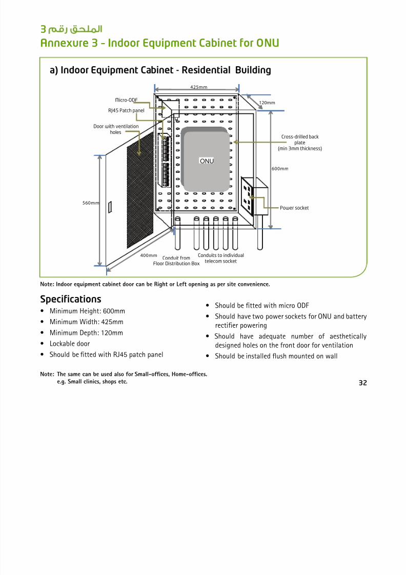
Annexure 3 – Indoor Equipment Cabinet for ONU
Note: Indoor equipment cabinet door can be Right or Left opening as per site convenience.
Note: The same can be used also for Small-offices, Home-offices. e.g. Small clinics, shops etc.
Specications• Minimum Height: 600mm
• Minimum Width: 425mm
• Minimum Depth: 120mm
• Lockable door
• Should be tted with RJ45 patch panel
• Should be tted with micro ODF
• Should have two power sockets for ONU and batteryrectifier powering
• Should have adequate number of aestheticallydesigned holes on the front door for ventilation
• Should be installed ush mounted on wall
32
a) Indoor Equipment Cabinet - Residential Building
ONU
Conduit fromFloor Distribution Box
Conduits to individualtelecom socket
425mm
120mm
Cross-drilled backplate
(min 3mm thickness)
Door with ventilationholes
560mm
400mm
Micro-ODF
Power socket
RJ45 Patch panel
600mm

8/18/2019 Ethisalat FTTH Design Guide
http://slidepdf.com/reader/full/ethisalat-ftth-design-guide 36/51
b) Indoor Equipment Cabinet - Commercial Building
Specications• Minimum Height: 600mm
• Minimum Width: 600mm
• Minimum Depth: 300mm
• Suitable for 19” rack equipment mount
• Lockable door
• Should be tted with RJ45 patch panel
• Should have two power sockets for ONU and batteryrectifier powering
• With provision for air circulation
• Partially concealed or Wall mount installation
33
600mm
600mm
300mm
Power socket
Micro-ODF
ONU
RJ45 Patch panel
Conduits to individual
telecom socket
Conduit from
Floor Distribution Box
Door with ventilationholes
Rack shelf
Note: This type of cabinet is applicable for commercial building with pre-defined offices and for big palaces.For commercial building with open-floor, Etisalat must be consulted.
ملحق رقم 4

8/18/2019 Ethisalat FTTH Design Guide
http://slidepdf.com/reader/full/ethisalat-ftth-design-guide 37/51
Annexure 4 – Fiber Distribution Hub (FDH)
I) Free standing type FDH cabinet
a) Specications
b) Free standing type FDH cabinet sample
• 42U rack cabinet ,2200mm X 600mm X 300mm(H x W x D)
• Suitable for 19-inch rack mounting equipment andSC/APC termination
• Standard mounting frame ETSI standard,
• Lightweight modular construction
• Cabinet design must be installed with access fromall sides
• Any metal parts must be free from sharp edges andmust be earthed / earth bonded in accordance withthe manufacture’s guidelines and safety standards.
34

8/18/2019 Ethisalat FTTH Design Guide
http://slidepdf.com/reader/full/ethisalat-ftth-design-guide 38/51
c) Free standing type FDH cabinet requirements
The following optical materials are required when a free standing type of FDH cabinets will be deployed.
• Telcordia qualied
• RoHS Complaint
• Return loss of 50dB
• SC/APC connectivity
• Operating temperature of -5˚C to +60˚C
• All bers are single mode (ITU-T-G.652)
Optical splitter module- specifications• Modular optical splitter, 2x32
• Compact size, rack mountable 19”.
• Wide operating wavelength range(1310/1490/1550/1620nm).
• Low insertion loss.
• Low Polarization Dependent Loss (PDL).
• Excellent Insertion Loss (IL) uniformity.
Optical patch panel module- specifications
• 24 Ports with SC/APC adapters
• Front plate compatible for SC/APC adapters
• Cable entry at the rear and sides of the module
• With cable manager (guide) and patching ring
• Capable of sliding or swiveling in when accessingthe interior of the module
• Must be equipped with splice trays
Optical patch cord- specifications
• Single mode SC/APC
• Low insertion loss.
• Wavelength 1260 – 1620 nm
• High return loss 50 dB.
• Good repeatability and exchangeability.• Operating temperature -20˚C to +60˚C
• LSOH and OFNR rated
• High Tensile Strength, min 10kgf
• Strength member cord, aramid yarn or Kevlar
• Typical length from 2 to 10 meters
• Diameter, 2mm/3mm
35

8/18/2019 Ethisalat FTTH Design Guide
http://slidepdf.com/reader/full/ethisalat-ftth-design-guide 39/51
d)To determine the quantity of Optical Splitter module and Optical PatchPanel module
e) Layout Plan for FDH (Free standing)
• To nd the Optical splitter quantity
Number of Tenants/32 (where splitter has 32 output ports)
Note: Etisalat must be consulted for splitter quantity in case ofcommercial buildings.
• To nd the Optical patch panel or drop module (Number Tenants)/24
(where patch panel has 24 ports)
• For Optical patch panel for feeder cable
Provide one dedicated 24-port patch panel forterminating Etisalat cable.
36
FDH Cabinet
(Free standing type)
0.5m
Front Side
1.0m
Minimum
distance
Minimum
distance
Main Telecom Room
Wall
Wall
II W ll FDH C bi 19” k i

8/18/2019 Ethisalat FTTH Design Guide
http://slidepdf.com/reader/full/ethisalat-ftth-design-guide 40/51
II. Wall-mount type FDH Cabinet-19” rack mounting
a) Specications• 12U – 22U 600 mm wide x 515 mm deep 19” wiring/
equipment cabinet
• Suitable for 19-inch rack mounting equipment andSC/APC termination
• Any metal parts must be free from sharp edges andmust be earthed / earth bonded in accordance withthe manufacture’s guidelines and safety standards.
b) Wall-mount type FDH Cabinet-19” requirementsThis type rack mountable FDH cabinet requires the following optical modules.
• Optical splitter module
• Optical patch panel
III.Wall-mount type FDH Cabinet with modular splitter
a) Specications• With one 2:32 Splitter pre-installed
• Dimension 970mm (L) X 640mm (W) X 160mm (D)• Maximum capacity of 128 connections
• Operating temperature: -40C to +65C
• RAL7038 colour
b) Sample Wall-mount FDH with modular type of splitter
• Patch cord
37
A 5 Fib O ti C bl O td D Cl Mi i ODF
ملحق رقم 5

8/18/2019 Ethisalat FTTH Design Guide
http://slidepdf.com/reader/full/ethisalat-ftth-design-guide 41/51
a) Fibre drop cable specications• Single mode
• Indoor drop bers
• Cable to be of at cross-section
• Suitable for SC/APC connectors
Annexure 5 – Fibre Optic Cable, Outdoor Drop Closure, Mini ODF
& Micro ODF
• Low friction
• Compliant with ITU-T G.652
• Flame Retardant Low Smoke Zero Halogen (LSZH)
b) Multicore cable specications• Characteristics conform to ITU-T G.652 standards
for single mode fiber.
• Mode eld diameter
-@ 1310 nm 8.6 ± 0.4 µm
-@ 1550 nm 9.8 ± 0.5 µm
• Cladding diameter 125 ± 1 µm
• Coating Diameter 245 ± 5 µm
• Cable16F or 24F core
• OFNR or OFNP listed
• Cable shall be all dielectric
• Thermoplastic buffer coating shall 900 + 50 um
• Buffered bers shall be surrounded with highmodulus strength yarn
• The jacket shall provide the cable with a tough,flexible, protective coating, able to withstand thestresses expected in normal installation and service
• The optical ber color coding shall be in accordanceto EIA/TIA-598
• The outer cable jacket shall be marked withmanufacturer’s name, date of manufacture, fiber
count, fiber type, flame rating, listing symbol andsequential length markings
• Operating temperature shall be -20 to +70 °C
• Rated tensile load of 200 N
• Attenuation: max 0.30 dB/Km (1550 nm) and max0.40/Km (1310 nm)
• Cut-off Wavelength 1190-1330 nm
• Fibre shall conform to ITU-T RecommendationG652D standards for single mode fibre
• Mode eld diameter @1310nm, 9.3±0.5µm
• Cladding diameter, 125±1µm
• Maximum attenuation,
@1310nm – 0.36dB/km@1550nm – 0.22dB/km
c) Outdoor Fibre Distribution Cable (Loose tube)
• 8F, 16F or 24F core
• Central strength member, steel stranded wire
38
d)Outdoor Drop Closure
8/18/2019 Ethisalat FTTH Design Guide
http://slidepdf.com/reader/full/ethisalat-ftth-design-guide 42/51
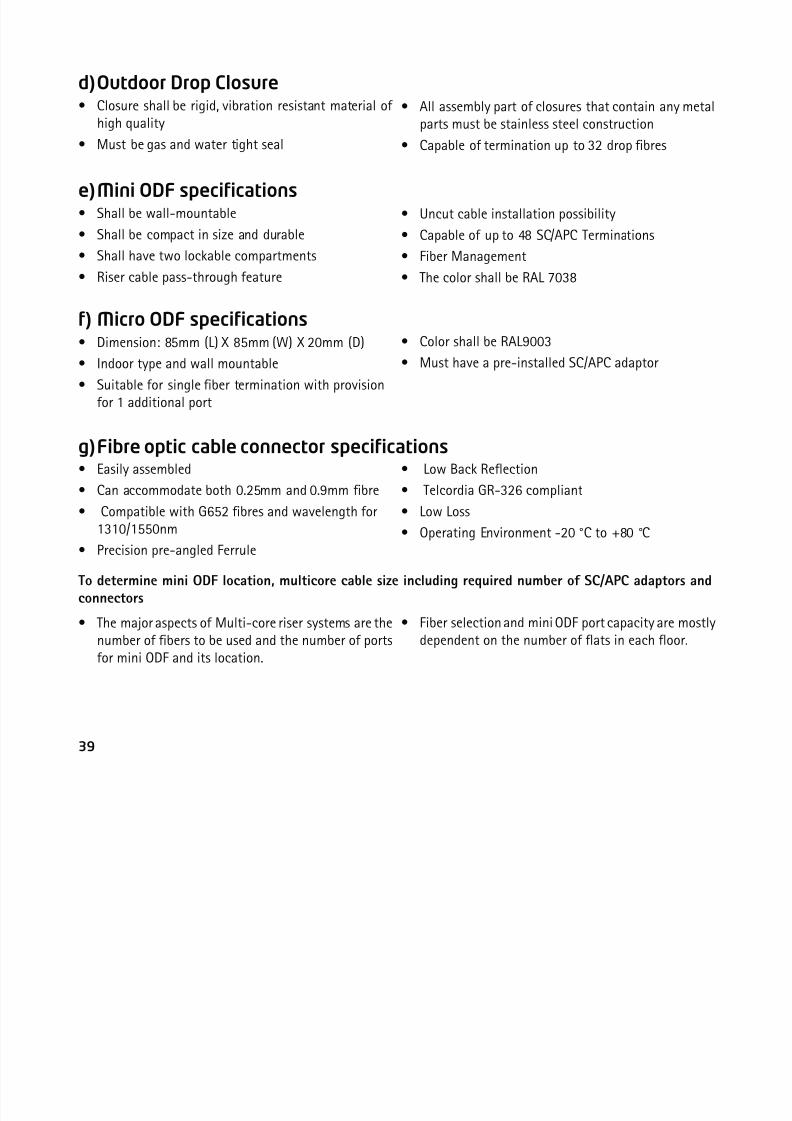
d) Outdoor Drop Closure• Closure shall be rigid, vibration resistant material of
high quality
• Must be gas and water tight seal
• All assembly part of closures that contain any metalparts must be stainless steel construction
• Capable of termination up to 32 drop bres
e) Mini ODF specications• Shall be wall-mountable
• Shall be compact in size and durable
• Shall have two lockable compartments
• Riser cable pass-through feature
• Uncut cable installation possibility
• Capable of up to 48 SC/APC Terminations
• Fiber Management
• The color shall be RAL 7038
f) Micro ODF specications• Dimension: 85mm (L) X 85mm (W) X 20mm (D)
• Indoor type and wall mountable
• Suitable for single ber termination with provisionfor 1 additional port
• Color shall be RAL9003
• Must have a pre-installed SC/APC adaptor
• Easily assembled
• Can accommodate both 0.25mm and 0.9mm bre
• Compatible with G652 bres and wavelength for1310/1550nm
• Precision pre-angled Ferrule
g) Fibre optic cable connector specications• Low Back Reection
• Telcordia GR-326 compliant
• Low Loss
• Operating Environment -20 °C to +80 °C
To determine mini ODF location, multicore cable size including required number of SC/APC adaptors andconnectors
• The major aspects of Multi-core riser systems are thenumber of fibers to be used and the number of portsfor mini ODF and its location.
• Fiber selection and mini ODF port capacity are mostlydependent on the number of flats in each floor.
39
Mini ODF location ber size required number of connectors and SC/APC adaptors can be determine as shown in

8/18/2019 Ethisalat FTTH Design Guide
http://slidepdf.com/reader/full/ethisalat-ftth-design-guide 43/51
Mini ODF location, ber size, required number of connectors and SC/APC adaptors can be determine as shown inthe matrix.
Tenants Per Floor Mini ODF Location Cable SizeNumber Of
SC/APC Adaptor
SC/APC Connector
(FDH To Mini ODF)1
Every 3 Floors 1X16F
3 6
2 6 123 9 184 12 245 15 30
6
Every 3 Floors 1X24F
18 36
7 21 428 24 48
9Every 3 Floors 2X16F
27 54
10 30 60
11
Every 3 Floors1X16F
&1X24F
33 66
12 36 72
13 39 78
14
Every 3 Floors 2X24F
42 84
15 45 90
16 48 96
17
Every 2 Floors1X16F
&1X24F
34 68
18 36 72
19 38 76
20 40 80
21
Every 2 Floors 2X24F
42 84
22 44 8823 46 92
24 48 96
25
Every 1 Floors 2X16F
25 50
26 26 52
27 27 54
28 28 56
29 29 5830 30 60
40

8/18/2019 Ethisalat FTTH Design Guide
http://slidepdf.com/reader/full/ethisalat-ftth-design-guide 44/51
Typical Multicore riser
cabling system
Outdoor bre distribution
cabling for complex of villa
41
Annexure 6 – FTTH test result & termination sheet
ملحق رقم 6

8/18/2019 Ethisalat FTTH Design Guide
http://slidepdf.com/reader/full/ethisalat-ftth-design-guide 45/51
42
Annexure 6 – FTTH test result & termination sheet
I. Test result sheets
a) Typical FTTH component lossesInsertion loss of FTTH components may differ based on the brand and make. The following are the typical insertion loss.
b) Splitter test result sheetTo ensure splitter is at its highest performance and to avoid installation of splitter with faulty ports, test of eachoutput ports must be provided in format shown below. Loss must not exceed the manufacturer’s insertion loss.
SN Description Value Unit
1 Optical Splitter, 2X32 17.2 dB
2 Fibre Drop Cable 0.35 dB/Km
3 Multicore Cable 0.25 dB/km
4 SC/APC Connector 0.4 dB
Emirates
Sector/Block Number Building Number/Name
Splitter No.Splitter Ports
Remarks1 2 3 4 5 - - 30 31 32
Splitter 1
Splitter 2
Splitter 3
Splitter 4
Splitter 5
Measurement Setting 1310nm/1550nm Date
c) Multicore cable test result sheet
8/18/2019 Ethisalat FTTH Design Guide
http://slidepdf.com/reader/full/ethisalat-ftth-design-guide 46/51
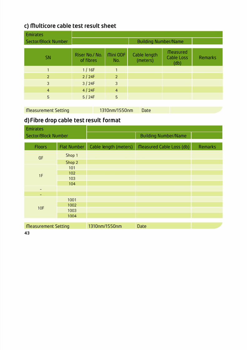
c) Multicore cable test result sheet
d) Fibre drop cable test result format
Emirates
Sector/Block Number Building Number/Name
SNRiser No./ No.
of bresMini ODF
No.Cable length
(meters)
MeasuredCable Loss
(db)Remarks
1 1 / 16F 1
2 2 / 24F 2
3 3 / 24F 3
4 4 / 24F 45 5 / 24F 5
Measurement Setting 1310nm/1550nm Date
Emirates
Sector/Block Number Building Number/Name
Floors Flat Number Cable length (meters) Measured Cable Loss (db) Remarks
GFShop 1
Shop 2
1F
101102
103104
--
10F
1001100210031004
Measurement Setting 1310nm/1550nm Date
43
II. Fibre connection details

8/18/2019 Ethisalat FTTH Design Guide
http://slidepdf.com/reader/full/ethisalat-ftth-design-guide 47/51
44
II. Fibre connection details
a) Direct bre termination
Emirates
Sector/block Number Building Number/Name
SPLITTER 1
Splitter Port No.Patch Panel
Flat No. NotesNo. Port
1 1 1 Shop 1 Modern Bakery2 1 2 Shop 2 German Rent-A-Car
3 1 3 Shop 3 The Textile Co.4 1 4 Shop 4 Clock Grocery5 1 5 MZ016 1 6 MZ027 1 7 MZ038 1 8 MZ049 1 9 10110 1 10 10211 1 11 103
12 1 12 10413 1 13 20114 1 14 20215 1 15 20316 1 16 20417 1 17 30118 1 18 30219 1 19 30320 1 20 304
21 1 21 40122 1 22 40223 1 23 40324 1 24 40425 2 1 50126 2 2 50227 2 3 50328 2 4 50429 2 5 60130 2 6 60231 2 7 60332 2 8 604
b) Multicore riser termination

8/18/2019 Ethisalat FTTH Design Guide
http://slidepdf.com/reader/full/ethisalat-ftth-design-guide 48/51
)
Emirates
Sector/block NumberBuilding
Number/NameSPLITTER 1
Splitter PortNo.
No. PortMini ODF
Flat No. NotesNo. Port Location
1 1 1 Shop 1 Direct connected from FDH/ Shop 12 1 2 Shop 2 Direct connected from FDH/ Shop 23 1 3 Shop 3 Direct connected from FDH/ Shop 34 1 4 Shop 4 Direct connected from FDH/ Shop 4
5 1 5 1 1 1F MZ016 1 6 1 2 1F MZ027 1 7 1 3 1F MZ038 1 8 1 4 1F MZ049 1 9 1 5 1F 10110 1 10 1 6 1F 10211 1 11 1 7 1F 10312 1 12 1 8 1F 104
13 1 13 1 9 1F 20114 1 14 1 10 1F 20215 1 15 1 11 1F 20316 1 16 1 12 1F 20417 1 17 2 1 4F 30118 1 18 2 2 4F 30219 1 19 2 3 4F 30320 1 20 2 4 4F 30421 1 21 2 5 4F 401
22 1 22 2 6 4F 40223 1 23 2 7 4F 40324 1 24 2 8 4F 40425 2 1 2 9 4F 50126 2 2 2 10 4F 50227 2 3 2 11 4F 50328 2 4 2 12 4F 50429 2 5 3 1 7F 601
30 2 6 3 2 7F 60231 2 7 3 3 7F 60332 2 8 3 4 7F 604
45
Annexure 7 – Cable labeling
ملحق رقم 7
8/18/2019 Ethisalat FTTH Design Guide
http://slidepdf.com/reader/full/ethisalat-ftth-design-guide 49/51
46
g
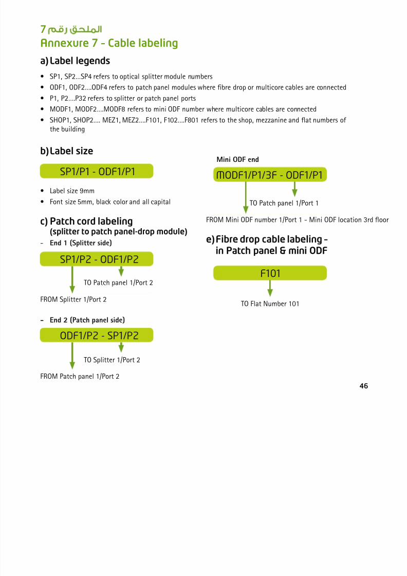
a) Label legends
• SP1, SP2…SP4 refers to optical splitter module numbers• ODF1, ODF2….ODF4 refers to patch panel modules where bre drop or multicore cables are connected
• P1, P2….P32 refers to splitter or patch panel ports
• MODF1, MODF2….MODF8 refers to mini ODF number where multicore cables are connected
• SHOP1, SHOP2…. MEZ1, MEZ2….F101, F102….F801 refers to the shop, mezzanine and at numbers ofthe building
b) Label size
SP1/P1 - ODF1/P1
• Label size 9mm
• Font size 5mm, black color and all capital
c) Patch cord labeling (splitter to patch panel-drop module)
- End 1 (Splitter side)
SP1/P2 - ODF1/P2
FROM Splitter 1/Port 2
TO Patch panel 1/Port 2
- End 2 (Patch panel side)
ODF1/P2 - SP1/P2
FROM Patch panel 1/Port 2
TO Splitter 1/Port 2
Mini ODF end
e) Fibre drop cable labeling –in Patch panel & mini ODF
MODF1/P1/3F - ODF1/P1
F101
FROM Mini ODF number 1/Port 1 - Mini ODF location 3rd oor
TO Patch panel 1/Port 1
TO Flat Number 101
ملحق رقم 8

8/18/2019 Ethisalat FTTH Design Guide
http://slidepdf.com/reader/full/ethisalat-ftth-design-guide 50/51
SN Descriptions Remarks
C. Patch Cord
1 Is the patch cord linking the splitter and patch panel (drop module) properly routed?
2 Is the patch cord arranged and properly secured?
3 Is patch cord bending does not exceeds maximum bending radius?
4 Is patch cord properly labeled?
D. Fibre Drop Cable (for direct bre & multicore riser)
1Is it made sure that cables are not in contact with any heating pipes located abovethe ceiling?
2 Are the drop cables from each floor bunched together for easy identification?
3 Is fibre cable fitted with the right connector?
4 Is fibre cable properly labeled?
47
Annexure 8 – FTTH Installation Checklist
SN Descriptions RemarksA. Fiber Distribution Hub (FDH)
1 Is the FDH secured properly?
2 Is FDH properly earthed?
3 Is FDH tidy and clean?
4 Is internal cable management properly done?
B. Optical Splitter and Patch Panel Modules
1 Is the Module (s) placed properly within the rack?
2 Does splitter rack have enough space for maintenance purpose?
3 Is the splitter and patch panel properly labeled?
4
E. Multicore Riser

8/18/2019 Ethisalat FTTH Design Guide
http://slidepdf.com/reader/full/ethisalat-ftth-design-guide 51/51
1 Are individual bers terminated based on EIA/TIA 568 standards?
2 Is individual fiber properly fitted with right connector?
3 Is multicore cable properly labeled?4
F. Mini ODF (for multicore riser)
1 Is the mini ODF properly fixed in the floor telephone room?
2 Is the mini ODF properly labeled?
G. Micro ODF
1 Is micro ODF properly fixed in the indoor equipment cabinet?H. UTP Cabling
1Is the total length of the CAT 6 cables including any patch cords or drop cables ateach end below 100 meters?
2 Are the cables do not have kinks and bends that exceed its minimum bending radius?
3Are the UTP CAT 6 cables are kept a safe 12 – inch separation from power cables andother potential sources of EMI (electrical cables, transformers, light fixtures, etc.) ?
4 Are all the communication sockets firmly fixed in the wall?
5 Does all the connection points and cables are properly labelled.
48
Annexure 9 – Structure Identication Plate
• EID Font type “ Arial Narrow” in Bold characters
• Etisalat logo in the middle top portion
• Details must be laser-printed/ engraved
ملحق رقم 9