ethernet networks redundancy with focus on iec 61850 ... 3/main... · • rstp (rapid spanning tree...
TRANSCRIPT

Prague, 8-11 June 2009
RMidence-Canada Session 3 Paper 0244
René MidenceRuggedCom Inc.
Vice-President MarketingPhone: +1 905 266 11 39Mobile: +1 647 504 58 15
E-mail: [email protected]
Ethernet Networks Redundancy With Focus On IEC 61850 Applications

Prague, 8-11 June 2009
RMidence-Canada Session 3 Paper 0244
Agenda• IEC61850 Process Overview• Basic Communications Network Topologies • Redundancy and OSI Model• Physical Redundancy• Layer 2 Redundancy Protocols
– Spanning Tree Protocol (STP; RSTP, MSTP)– Link Aggregation Control Protocol (LACP)
• Summary

Prague, 8-11 June 2009
RMidence-Canada Session 3 Paper 0244
IEC61850 Process - System Design• Substation protection design Two independent
protection systems:– Protection A – Protection B
• Two protection relays from different manufacturers• Individually connected to the process equipment• Similar redundancy is required in the Ethernet
network for IEC 61850 applications• Duplication is required in:
– IEDs– Communication system.
Prague, 8-11 June 2009
RMidence-Canada Session 3 Paper 0244
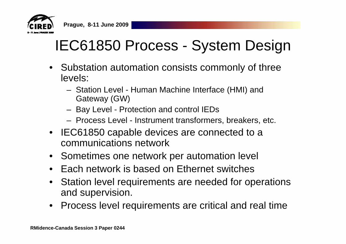
IEC61850 Process - System Design• Substation automation consists commonly of three
levels:– Station Level - Human Machine Interface (HMI) and
Gateway (GW)– Bay Level - Protection and control IEDs– Process Level - Instrument transformers, breakers, etc.
• IEC61850 capable devices are connected to a communications network
• Sometimes one network per automation level• Each network is based on Ethernet switches • Station level requirements are needed for operations
and supervision.• Process level requirements are critical and real time
Prague, 8-11 June 2009
RMidence-Canada Session 3 Paper 0244
IEC
6185
0P
roce
ss B
usIE
C61
850
Sta
tion
Bus
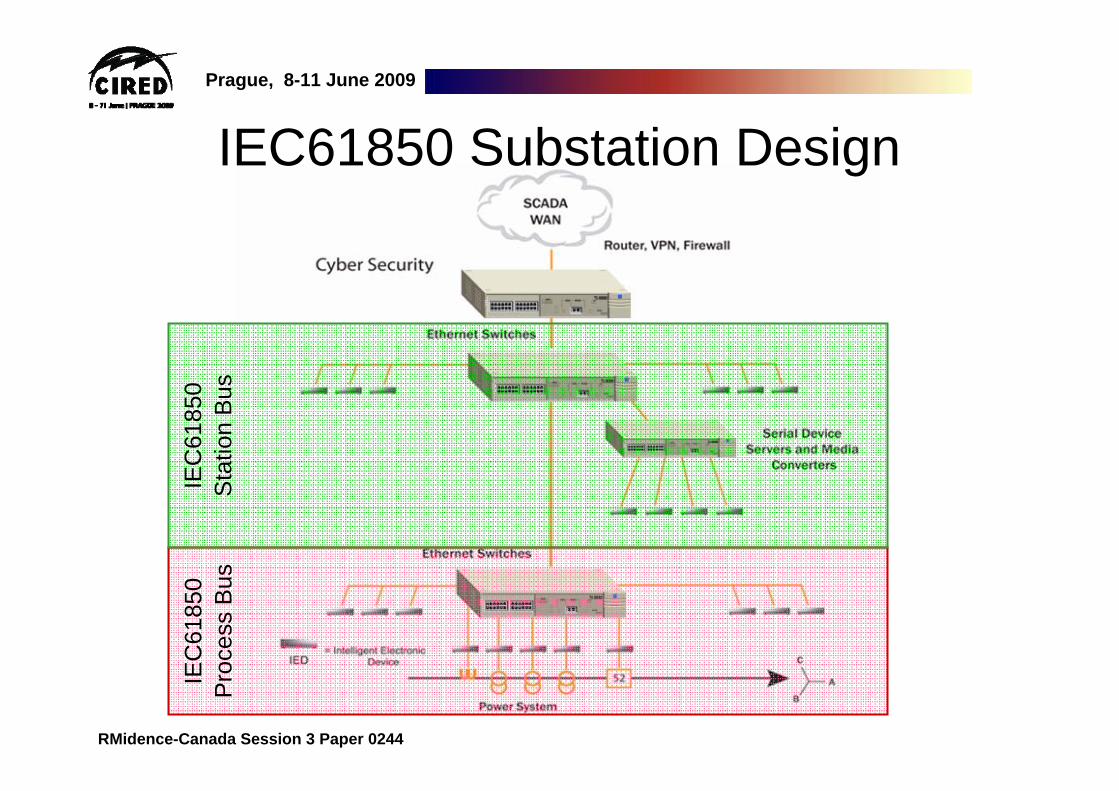
IEC61850 Substation Design

Prague, 8-11 June 2009
RMidence-Canada Session 3 Paper 0244
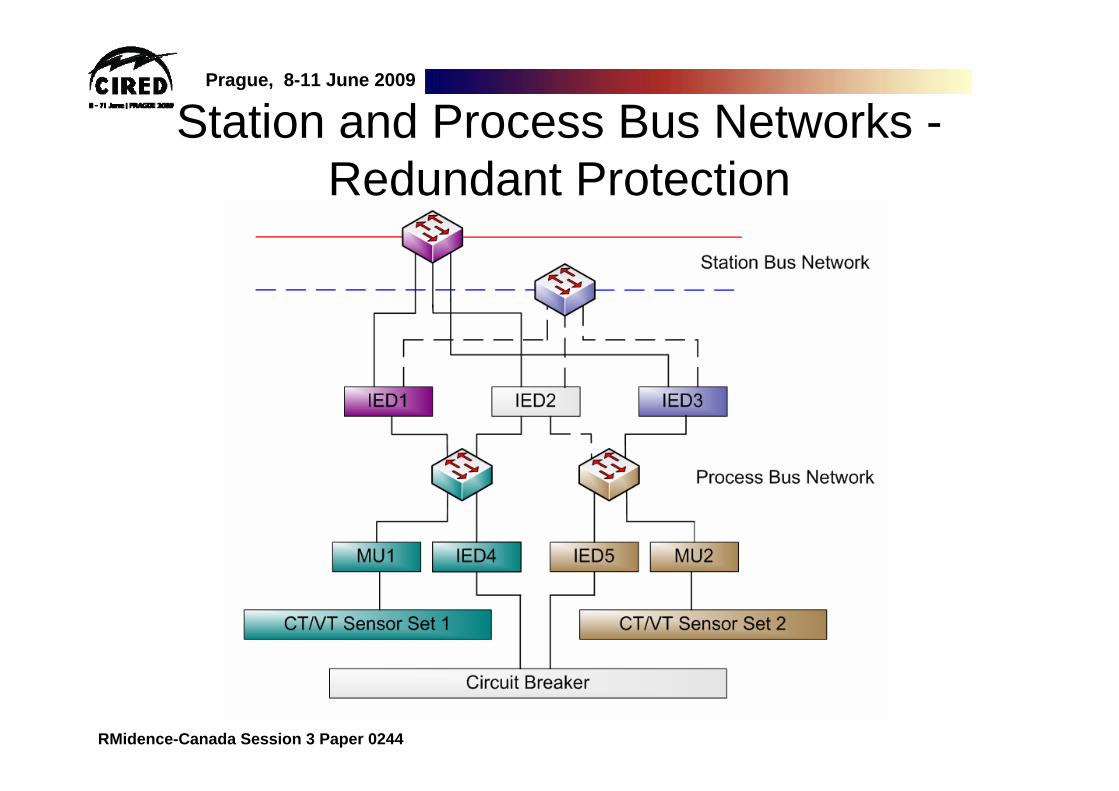
IEC61850 Substation Design• In the Process Bus information exchange is real time• Most critical information exchange is related to
protection• Protection is achieved as follows:
– Sampled values from the instrument transformers to the protection relay
– Application of P&C algorithms– Execution of commands
• trip command relay to breaker• interlocking commands between relays (per-to-peer
communications)• Acceptable maximum communication delay is as low
as 3 ms. • Achieved independent from the load of the
communication network.
Prague, 8-11 June 2009
RMidence-Canada Session 3 Paper 0244
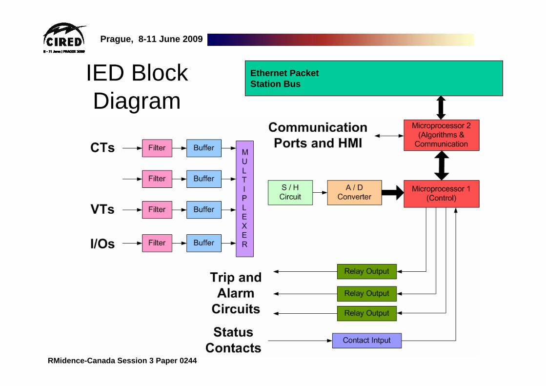
Ethernet Packet Station Bus
IED Block Diagram

Prague, 8-11 June 2009
RMidence-Canada Session 3 Paper 0244
Ethernet Packet Station Bus
Status, Trips, Close, GOOSE / GSSE
A, V, Hz, W, Wh, Var, Varh, SOEIED Block
Diagram

Prague, 8-11 June 2009
RMidence-Canada Session 3 Paper 0244
Ethernet Packet Process Bus
Merging Unit Block Diagram
I/Os
I/OsI/Os
Process Bus data is used by other IEDs in the network to perform real time protection & control mission critical actions
Prague, 8-11 June 2009
RMidence-Canada Session 3 Paper 0244
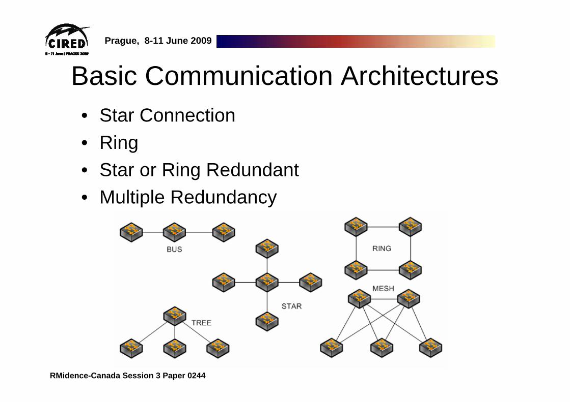
Basic Communication Architectures• Star Connection• Ring • Star or Ring Redundant • Multiple Redundancy

Prague, 8-11 June 2009
RMidence-Canada Session 3 Paper 0244
Non-redundant Star Communication System

Prague, 8-11 June 2009
RMidence-Canada Session 3 Paper 0244
Doubled Parallel Redundant Network

Prague, 8-11 June 2009
RMidence-Canada Session 3 Paper 0244
Communications System with Ring Redundancy
Prague, 8-11 June 2009
RMidence-Canada Session 3 Paper 0244
Station and Process Bus Networks -Redundant Protection
Prague, 8-11 June 2009
RMidence-Canada Session 3 Paper 0244
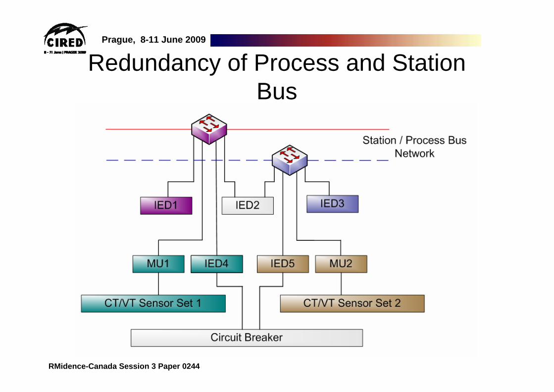
Redundancy of Process and Station Bus

Prague, 8-11 June 2009
RMidence-Canada Session 3 Paper 0244
Redundancy and the OSI Model• Areas for Ethernet-based
controls redundancy:– Physical– Data link– Network
• The lower in the OSI model, the greater the impact of failures that occur

Prague, 8-11 June 2009
RMidence-Canada Session 3 Paper 0244
Physical Security• Physical security covers:
– Physical Ethernet network connections– Physical hardware
• Network redundancy implies multiple routs between devices
• Physical redundancy scenarios:– Diverse routing of cables– Redundant hardware including:
• Redundant power supplies• Multiple CPU cards
• Considerations for redundancy– What is the application?– Area of coverage including number of devices
Prague, 8-11 June 2009
RMidence-Canada Session 3 Paper 0244
Physical Redundancy Check ListTo make decisions on physical redundancy, one must ask:• Are devices grouped according to location and function? • What will be the application performed? • Device type? • Will there be a requirement to connect to the existing Substation
Backbone network?
Answer to above questions will assist to decide:• How the Ethernet network will look like • Number of ports required on the Ethernet switches• Number of cables• Physical routing of the cables• Location of network nodes
Prague, 8-11 June 2009
RMidence-Canada Session 3 Paper 0244
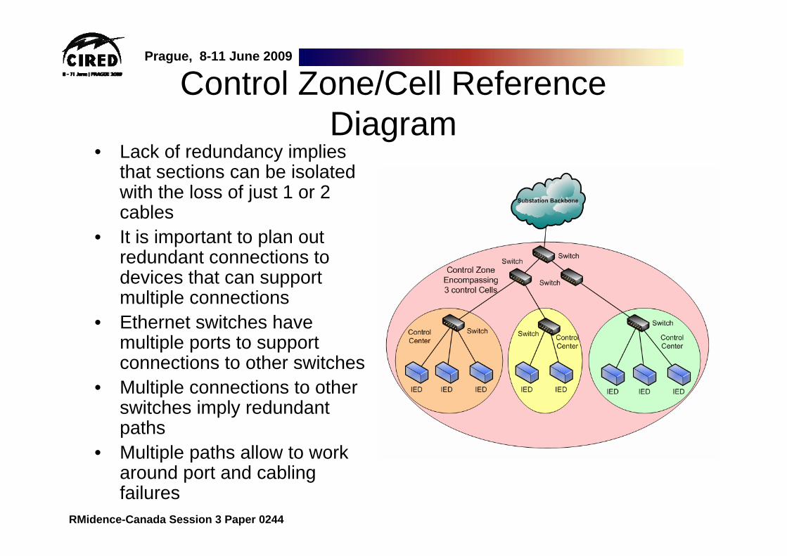
Control Zone/Cell Reference Diagram
• Lack of redundancy implies that sections can be isolated with the loss of just 1 or 2 cables
• It is important to plan out redundant connections to devices that can support multiple connections
• Ethernet switches have multiple ports to support connections to other switches
• Multiple connections to other switches imply redundant paths
• Multiple paths allow to work around port and cabling failures
Prague, 8-11 June 2009
RMidence-Canada Session 3 Paper 0244
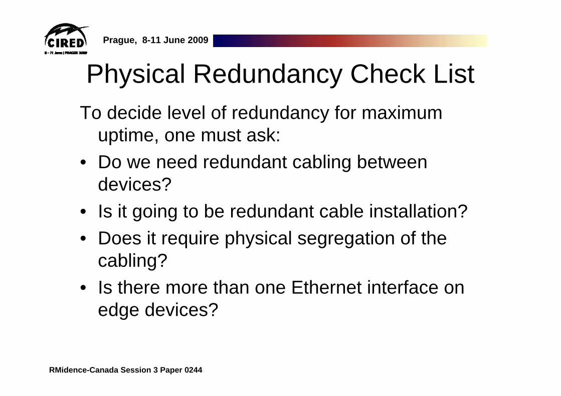
Physical Redundancy Check ListTo decide level of redundancy for maximum
uptime, one must ask:• Do we need redundant cabling between
devices? • Is it going to be redundant cable installation?• Does it require physical segregation of the
cabling? • Is there more than one Ethernet interface on
edge devices?

Prague, 8-11 June 2009
RMidence-Canada Session 3 Paper 0244
Layer 2 Redundancy Protocols• Identify all the possible paths amongst the
networking devices • Place the redundant extra paths in a blocking
state to remove network loops• In the event network segment failure,
unblocks segments to reestablish connectivity• Fixes the issue before the process even
knows there is a problem
Prague, 8-11 June 2009
RMidence-Canada Session 3 Paper 0244
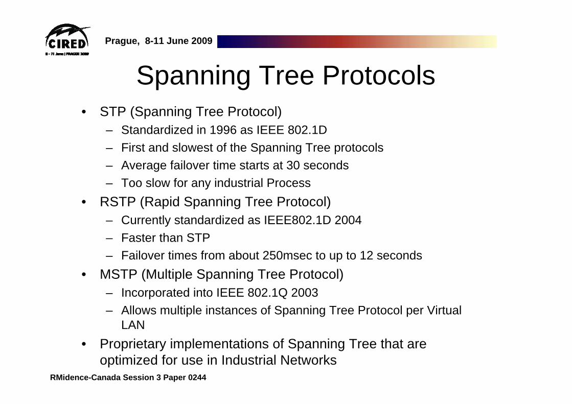
Spanning Tree Protocols• STP (Spanning Tree Protocol)
– Standardized in 1996 as IEEE 802.1D– First and slowest of the Spanning Tree protocols– Average failover time starts at 30 seconds– Too slow for any industrial Process
• RSTP (Rapid Spanning Tree Protocol)– Currently standardized as IEEE802.1D 2004– Faster than STP– Failover times from about 250msec to up to 12 seconds
• MSTP (Multiple Spanning Tree Protocol) – Incorporated into IEEE 802.1Q 2003– Allows multiple instances of Spanning Tree Protocol per Virtual
LAN• Proprietary implementations of Spanning Tree that are
optimized for use in Industrial Networks

Prague, 8-11 June 2009
RMidence-Canada Session 3 Paper 0244
N+1 Redundancy via RSTP

Prague, 8-11 June 2009
RMidence-Canada Session 3 Paper 0244
RSTP After Failure

Prague, 8-11 June 2009
RMidence-Canada Session 3 Paper 0244
RSTP + Dual Homed IED

Prague, 8-11 June 2009
RMidence-Canada Session 3 Paper 0244
Link Aggregation Control Protocol• Allows the configuration of multiple Ethernet ports
between Ethernet switches into a Single virtual “Link”• Allows load sharing of information between the links• Extremely fast in moving data between ports in the
event of port failure• Bundle groups of ports to form one virtual link• Bandwidth is of the member links• Provides redundancy without the use of Spanning
Tree

Prague, 8-11 June 2009
RMidence-Canada Session 3 Paper 0244
Link Aggregation Control ProtocolLACP provides several functions:• Higher bandwidth• Enhanced Bandwidth Granularity• Load sharing across the member links• Balance bandwidth across the member links• Fault tolerance provided by offloading data to
working member links when a member link fails
Prague, 8-11 June 2009
RMidence-Canada Session 3 Paper 0244
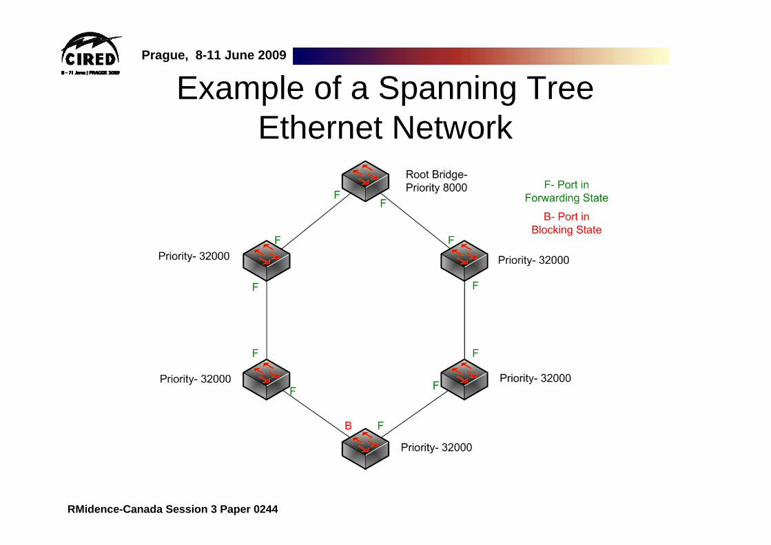
Example of a Spanning Tree Ethernet Network

Prague, 8-11 June 2009
RMidence-Canada Session 3 Paper 0244
Summary• It is important to understand the relationships between:
– The physical structure of a network– The protocols that run on the network
• Key to creating a truly maintainable and adaptable network that deals with issues effectively.
• Reconfiguration time is a critical issue for safety• Use Ethernet switches with fastest rapid spanning tree• Use fastest RST for mission critical applications such as
GOOSE messages between IEDs• For higher availability use doubled communication networks• In HV substations, all bays are protected by redundant
protection (Protection A, Protection B)• The related process bus has to be doubled by definition to avoid
a single point of failure

Prague, 8-11 June 2009
RMidence-Canada Session 3 Paper 0244
René MidenceRuggedCom Inc.
Vice-President, MarketingPhone: +1 905 266 11 39Mobile: +1 647 504 58 15
E-mail: [email protected]
Thank You!Questions?