ethernet network redundancy in scada and real-time ... · umbrella terms used for link aggregation...
TRANSCRIPT
Ethernet Network Redundancy in
SCADA and real-time Automation
Platforms
www.copadata.com
1
Content
1. ABSTRACT .......................................................................................................... 2
2. INTRODUCTION .................................................................................................. 2
IEC 61850 COMMUNICATION SERVICES ................................................................ 2
APPLICATION AND ARCHITECTURE REQUIREMENTS......................................... 3
3. NETWORK REDUNDANCY ................................................................................. 4
RAPID SPANNING TREE PROTOCOL ..................................................................... 4
LINK AGGREGATION ................................................................................................ 5
4. BUMPLESS REDUNDANCY WITH PRP AND HSR ............................................ 6
PRP OPERATING PRINCIPLE .................................................................................. 7
HSR OPERATING PRINCIPLE .................................................................................. 8
5. ARCHITECTURE COMPARISON ...................................................................... 10
6. CONCLUSIONS ................................................................................................. 12

Abstract
2
1. Abstract
The international IEC 61850 ‘Communication and Systems for Power Utility Automation’
standard provides for standardized methods of communication between devices connected
together on an Ethernet network to perform critical protection, monitoring, metering and control
functions.
The SCADA component is an essential part of an IEC 61850-based substation automation
system. It provides the operator interface to monitor and control the primary plant equipment
and is therefore critical for the ongoing operation of a substation. SCADA systems are often
designed for high availability, especially at higher voltage levels, and this is achieved through
the implementation of redundant systems and redundant Ethernet communication interfaces.
The international standard IEC 62439 introduces the Ethernet OSI (Open System
Interconnection model), Layer 2 redundancy protocols, Parallel Redundancy Protocol (PRP)
and High-availability Seamless Redundancy (HSR). These protocols provide ‘bumpless’
redundancy with the 0 ms failover time required by critical high-speed functions.
This paper identifies the Ethernet failover, latency and speed requirements for various SCADA
and automation functions. Different Ethernet redundancy architectures are explained,
compared and examined for suitability in a SCADA and automation environment. The
comparison shows that SCADA systems using a combination of Link Aggregation and the
Rapid Spanning Tree Protocol (RSTP) can meet the performance requirements for IEC 61850
Client/Server communication at a low cost. However, SCADA systems performing critical high-
speed functions such as load shedding via IEC 61850 GOOSE require a better failover
performance which can only be met with PRP and HSR redundancy protocols.
It also discusses the importance of the Quality of Service (QoS) configuration and network
monitoring in high-availability Ethernet and SCADA architectures.
2. Introduction
IEC 61850 Communication Services
The IEC 61850 standard has been widely and globally adopted in the electricity industry since
its first release in 2003. IEC 61850 systems rely on an Ethernet communication network to
Introduction
3
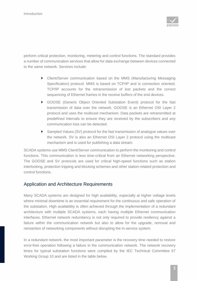
perform critical protection, monitoring, metering and control functions. The standard provides
a number of communication services that allow for data exchange between devices connected
to the same network. Services include:
Client/Server communication based on the MMS (Manufacturing Messaging
Specification) protocol. MMS is based on TCP/IP and is connection oriented.
TCP/IP accounts for the retransmission of lost packets and the correct
sequencing of Ethernet frames in the receive buffers of the end devices.
GOOSE (Generic Object Oriented Substation Event) protocol for the fast
transmission of data over the network. GOOSE is an Ethernet OSI Layer 2
protocol and uses the multicast mechanism. Data packets are retransmitted at
predefined intervals to ensure they are received by the subscribers and any
communication loss can be detected.
Sampled Values (SV) protocol for the fast transmission of analogue values over
the network. SV is also an Ethernet OSI Layer 2 protocol using the multicast
mechanism and is used for publishing a data stream.
SCADA systems use MMS Client/Server communication to perform the monitoring and control
functions. This communication is less time-critical from an Ethernet networking perspective.
The GOOSE and SV protocols are used for critical high-speed functions such as station
interlocking, protection tripping and blocking schemes and other station-related protection and
control functions.
Application and Architecture Requirements
Many SCADA systems are designed for high availability, especially at higher voltage levels
where minimal downtime is an essential requirement for the continuous and safe operation of
the substation. High availability is often achieved through the implementation of a redundant
architecture with multiple SCADA systems, each having multiple Ethernet communication
interfaces. Ethernet network redundancy is not only required to provide resiliency against a
failure within the communication network but also to allow for the upgrade, removal and
reinsertion of networking components without disrupting the in-service system.
In a redundant network, the most important parameter is the recovery time needed to restore
error-free operation following a failure in the communication network. The network recovery
times for typical substation functions were compiled by the IEC Technical Committee 57
Working Group 10 and are listed in the table below.

Network Redundancy
4
Communication Partners &
Application
Communication
Service
Required
Communication
Recovery Time
SCADA to IED, Client/Server IEC 61850 MMS 100 ms
IED to IED, slow automated controls
e.g. interlocking
IEC 61850 GOOSE 4 ms
IED to IED, fast automated controls
e.g. load shedding, reverse blocking
IEC 61850 GOOSE 4 ms
IED to IED, fast tripping e.g. bus bar
protection trip
IEC 61850 GOOSE Bumpless
IED to IED, sampled values for bus
bar protection
IEC 61850 SV Bumpless
Table 1: Network recovery times for typical substation functions
Computing platforms running SCADA have become a lot more capable in recent years and
there is a continuing trend to integrate some high-speed automation functions such as reverse
blocking or load shedding schemes into these platforms in an attempt to reduce device count
and cost. The aggregation of such functions converts a SCADA system effectively into an
automation platform, but must meet real-time requirements.
3. Network Redundancy
The concept behind network redundancy is to provide alternate communication paths between
the source and destination devices. As standard, Ethernet does not allow rings or loops in the
network as this would result in data frames circulating endlessly and flooding the network. The
network infrastructure must therefore support redundancy protocols designed to negate the
usual problems of putting loops into an Ethernet network, maintaining a default data path and
switching to an alternate one when a fault occurs.
Rapid Spanning Tree Protocol
The Ethernet OSI Layer 2 redundancy protocol Rapid Spanning Tree Protocol (RSTP)
prevents the problem of loops by forming a logical tree network that spans all switches on the
network. At the base of the tree is the ‘Root Bridge’ which is preconfigured via the ‘Root Priority’
attribute or selected by the network switches based on the MAC address of their network

Network Redundancy
5
management ports. RSTP ensures that certain links in the network are put into a backup state
so that no traffic may flow across the link, thus breaking any physical loops in the network as
shown in Figure 1. If network problems occur the backup links are re-enabled as needed to
restore connectivity to all devices. The automatic network fault recovery is rapid in order to
minimize data loss and to ensure the proper functioning of the system. RSTP is capable of
recovering a network within a few hundred milliseconds if properly configured. Faster recovery
times can be achieved with vendor-proprietary extensions added to RSTP.
Figure 1: Rapid Spanning Tree Protocol
Link Aggregation
The term ‘Link Aggregation’ applies to various methods of combining multiple network
connections in parallel in order to increase throughput or, more important from a SCADA
perspective, to provide redundancy in case one of the network connections fails. Other
umbrella terms used for link aggregation include port trunking, link bundling or NIC/port
teaming. These terms encompass not only standards-based solutions such as the Link
Aggregation Control Protocol (LACP) but also various proprietary solutions. Aggregation can
be implemented based on Ethernet OSI Layer 2 or Layer 3.

Bumpless Redundancy with PRP and HSR
6
The most common method used to achieve communication redundancy in a SCADA system
has been a combination of link aggregation and RSTP, as illustrated in Figure 2, with Servers
A and B representing a redundant pair of SCADA computers that support link aggregation
connected to a simple Ethernet ring using RSTP. The two Ethernet switches connecting
Servers A and B to the network are required to avoid a single point of failure. The use of two
standards and technologies provide a true N-1 redundancy. Failover times are typically in the
range of seconds but can potentially be reduced to a few hundred milliseconds.
Figure 2: Simple Ring with link aggregation and RSTP
High-speed automation functions such as a load shedding scheme or safety integrity protection
scheme that rely on the GOOSE communication mechanism may not tolerate the switchover
times provided in the solution above. The basis for such high-speed automation functions
would have to be two independent active paths between two devices.
4. Bumpless Redundancy with PRP and HSR
The international standard IEC 62439 introduces new concept of high availability networks and
defines the Ethernet OSI Layer 2 protocols Parallel Redundancy Protocol (PRP) and High-
availability Seamless Redundancy (HSR). These protocols provide ‘bumpless’ redundancy
with 0 ms failover time, as required by critical high-speed functions. The sender uses two
independent network interfaces that transmit the same data simultaneously. The redundancy
monitoring protocol then ensures that the recipient uses only the first data packet and discards
the second. If only one packet is received, the recipient knows that a failure has occurred on
the other path.
Bumpless Redundancy with PRP and HSR
7
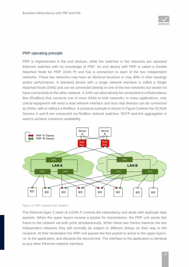
PRP operating principle
PRP is implemented in the end devices, while the switches in the networks are standard
Ethernet switches with no knowledge of PRP. An end device with PRP is called a Double
Attached Node for PRP (DAN P) and has a connection to each of the two independent
networks. These two networks may have an identical structure or may differ in their topology
and/or performance. A standard device with a single network interface is called a Single
Attached Node (SAN) and can be connected directly to one of the two networks but would not
have connectivity to the other network. A SAN can alternatively be connected to a Redundancy
Box (RedBox) that connects one or more SANs to both networks. In many applications, only
critical equipment will need a dual network interface and less vital devices can be connected
as SANs, with or without a RedBox. A practical example is shown in Figure 3 where the SCADA
Servers A and B are connected via RedBox network switches. RSTP and link aggregation is
used to achieve maximum availability.
Figure 3: PRP network with RedBox
The Ethernet layer 2 stack of a DAN P controls the redundancy and deals with duplicate data
packets. When the upper layers receive a packet for transmission, the PRP unit sends this
frame to the network via both ports simultaneously. When these two frames traverse the two
independent networks they will normally be subject to different delays on their way to the
recipient. At their destination the PRP unit passes the first packet to arrive to the upper layers,
i.e. to the application, and discards the second one. The interface to the application is identical
to any other Ethernet network interface.
Bumpless Redundancy with PRP and HSR
8
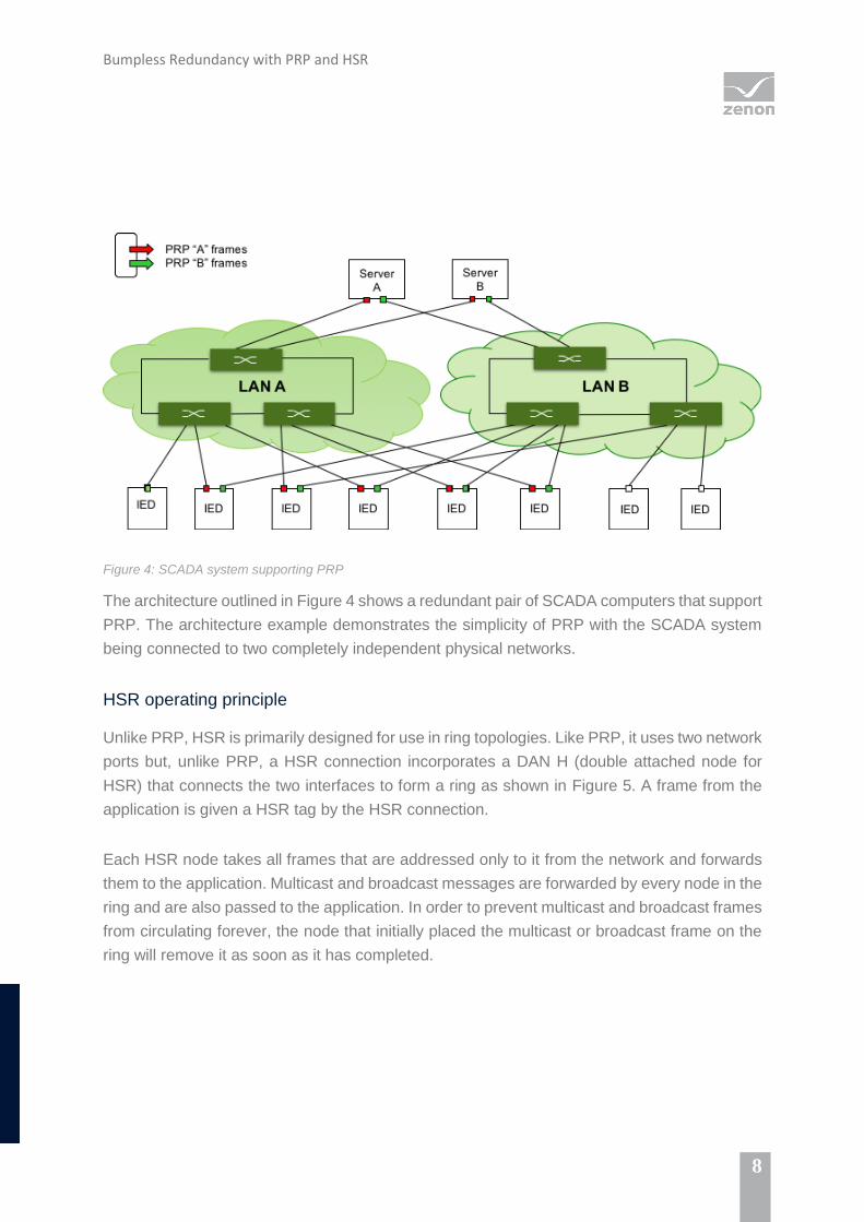
Figure 4: SCADA system supporting PRP
The architecture outlined in Figure 4 shows a redundant pair of SCADA computers that support
PRP. The architecture example demonstrates the simplicity of PRP with the SCADA system
being connected to two completely independent physical networks.
HSR operating principle
Unlike PRP, HSR is primarily designed for use in ring topologies. Like PRP, it uses two network
ports but, unlike PRP, a HSR connection incorporates a DAN H (double attached node for
HSR) that connects the two interfaces to form a ring as shown in Figure 5. A frame from the
application is given a HSR tag by the HSR connection.
Each HSR node takes all frames that are addressed only to it from the network and forwards
them to the application. Multicast and broadcast messages are forwarded by every node in the
ring and are also passed to the application. In order to prevent multicast and broadcast frames
from circulating forever, the node that initially placed the multicast or broadcast frame on the
ring will remove it as soon as it has completed.

Bumpless Redundancy with PRP and HSR
9
Figure 5: HSR network
In contrast with PRP, it is not possible to integrate SAN nodes directly into a HSR network
without breaking the ring. This is one reason why SANs can be connected to HSR networks
only via redundancy boxes.
HSR behaves just like PRP by sending duplicate frames from both ports. In the event of a
failure, one frame will still be transmitted via whichever network path is still intact. This means
that the redundancy again functions with zero switchover time and, unlike PRP, does not
require two parallel networks. A HSR network, however, always has the form of a ring, or a
structure of coupled rings, which means that it is less flexible than PRP at the installation stage.
The duplicate transmission of frames in both directions also means that effectively only 50%
of the network bandwidth is available for data traffic.

Architecture Comparison
10
5. Architecture Comparison
The goal of deploying a redundant network is to guarantee packet delivery in a timely way for
the various applications. A comparison of the different network redundancy protocols is
provided in the following table, which outlines some of the advantages and disadvantages of
each redundancy option.
Architecture Option Advantages and Disadvantages
RSTP / Port Teaming Advantages:
Meets communication recovery times for most
SCADA applications if configured correctly.
Readily supported in most networking devices.
Disadvantages:
Slow with some variability in communication
latency depending on network topology.
Not suitable for applications that require fast
communication recovery times.
Interoperability can be an issue because of the
vast variety of standards and proprietary link
aggregation protocols.
Configuration for interconnected networks can
be complex.
PRP Advantages:
Can run on two independent networks and
therefore suitable for hot swap - 24h/365d
operation of network devices.
Can be used in a simple star architecture or
any other topology.
Uses off-the-shelf network components.
Tolerates any single network component
failure.
Is transparent and achieves zero recovery
time (bumpless redundancy).
Supervises redundancy continuously for
device management.
Devices with single and double network
attachments can be used on the same LAN.
Laptops and workstations can connect to the
network using standard Ethernet adapters.
Disadvantages:
Duplication of network equipment and cabling.
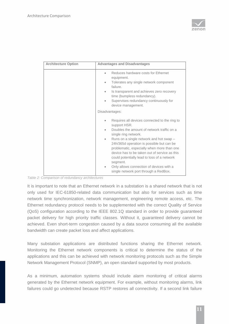
HSR Advantages:
Architecture Comparison
11
Architecture Option Advantages and Disadvantages
Reduces hardware costs for Ethernet
equipment.
Tolerates any single network component
failure.
Is transparent and achieves zero recovery
time (bumpless redundancy).
Supervises redundancy continuously for
device management.
Disadvantages:
Requires all devices connected to the ring to
support HSR.
Doubles the amount of network traffic on a
single ring network.
Runs on a single network and hot swap –
24h/365d operation is possible but can be
problematic, especially when more than one
device has to be taken out of service as this
could potentially lead to loss of a network
segment.
Only allows connection of devices with a
single network port through a RedBox.
Table 2: Comparison of redundancy architectures
It is important to note that an Ethernet network in a substation is a shared network that is not
only used for IEC-61850-related data communication but also for services such as time
network time synchronization, network management, engineering remote access, etc. The
Ethernet redundancy protocol needs to be supplemented with the correct Quality of Service
(QoS) configuration according to the IEEE 802.1Q standard in order to provide guaranteed
packet delivery for high priority traffic classes. Without it, guaranteed delivery cannot be
achieved. Even short-term congestion caused by a data source consuming all the available
bandwidth can create packet loss and affect applications.
Many substation applications are distributed functions sharing the Ethernet network.
Monitoring the Ethernet network components is critical to determine the status of the
applications and this can be achieved with network monitoring protocols such as the Simple
Network Management Protocol (SNMP), an open standard supported by most products.
As a minimum, automation systems should include alarm monitoring of critical alarms
generated by the Ethernet network equipment. For example, without monitoring alarms, link
failures could go undetected because RSTP restores all connectivity. If a second link failure

Conclusions
12
then occurred, it could cause many IEDs to be isolated from the network – leading to poor
operation of protection schemes and loss of data.
6. Conclusions
The comparison of different Ethernet redundancy protocols shows that SCADA systems using
a combination of link aggregation and Rapid Spanning Tree Protocol (RSTP) can meet the
performance requirements for IEC 61850 Client/Server communication at a low cost. However,
detailed configuration of the Ethernet network adapters and Ethernet switches is required to
achieve guaranteed faster failover times.
If critical high-speed functions are running on a SCADA system, the use of PRP or HSR is
recommended to achieve fast network failover times. PRP provides benefits with regards to
the operation and maintenance of the system as it is based on using two separate and
independent physical networks. For this reason, PRP may be selected for solutions that do not
require bumpless redundancy but do need high network availability.
HSR networks do not require separate Ethernet network equipment but devices not supporting
HSR can only be connected via RedBox.
Irrespective of which network redundancy method is used, QoS and network and device
monitoring should be applied in the network design to ensure Ethernet networking issues can
be monitored and alarms set to prevent loss of functionality and/or data.
Would you like to have an expert advise you on this topic? Please contact:
www.copadata.com

13
© Ing. Punzenberger COPA-DATA GmbH.
All rights reserved. This document is protected by copyright and may not be reproduced, utilized or photocopied in
any form or by any means without permission in writing from Ing. Punzenberger COPA-DATA GmbH. The technical
data contained herein have been provided solely for informational purposes and are not legally binding. The COPA-
DATA logo, zenon, zenon Analyzer, zenon Supervisor, zenon Operator, zenon Logic and straton are registered
trademarks of Ing. Punzenberger COPA-DATA GmbH. All other brands and product names may be the trademarks
or registered trademarks of their representative owners. Subject to change, technical or otherwise.