ethercat v1000 tm a4
TRANSCRIPT

YASKAWA EUROPE GMBH YEU SIEP C710606 98A - AC Drive V1000 Option EtherCAT - Technical Manual 1MANUAL NO. YEU SIEP C710606 98A
To properly use the product, read this manual thoroughly and retain for easy reference, inspection, and maintenance. Ensure the end user receives this manual.
Type: SI-ES3 for V1000 Series
Technical Manual
YASKAWA AC Drive V1000 Option
ATTENTION! This product can only be used on V1000 drives with firmware version VSV901020 to VSV901099 installed.


Table of Contents
1 PREFACE AND SAFETY . . . . . . . . . . . . . . . . . . . . . . . . . . . . . . . . . . . . . . . . . . . . . . . . . . . . . . . . . . . . . . . . 42 PRODUCT OVERVIEW. . . . . . . . . . . . . . . . . . . . . . . . . . . . . . . . . . . . . . . . . . . . . . . . . . . . . . . . . . . . . . . . . . 63 SOFTWARE PARTS. . . . . . . . . . . . . . . . . . . . . . . . . . . . . . . . . . . . . . . . . . . . . . . . . . . . . . . . . . . . . . . . . . . . 74 RECEIVING. . . . . . . . . . . . . . . . . . . . . . . . . . . . . . . . . . . . . . . . . . . . . . . . . . . . . . . . . . . . . . . . . . . . . . . . . . . 85 ETHERCAT® OPTION COMPONENTS. . . . . . . . . . . . . . . . . . . . . . . . . . . . . . . . . . . . . . . . . . . . . . . . . . . . . 96 INSTALLATION PROCEDURE . . . . . . . . . . . . . . . . . . . . . . . . . . . . . . . . . . . . . . . . . . . . . . . . . . . . . . . . . . 127 DSP301 AND DSP402 SPECIFICATIONS. . . . . . . . . . . . . . . . . . . . . . . . . . . . . . . . . . . . . . . . . . . . . . . . . . 168 ETHERCAT® OPTION RELATED DRIVE PARAMETERS . . . . . . . . . . . . . . . . . . . . . . . . . . . . . . . . . . . . . 219 OBJECT DICTIONARY. . . . . . . . . . . . . . . . . . . . . . . . . . . . . . . . . . . . . . . . . . . . . . . . . . . . . . . . . . . . . . . . . 2210 CONFIGURING MANUFACTURER SPECIFIC CANOPEN OBJECTS. . . . . . . . . . . . . . . . . . . . . . . . . . . 3711 PROCESS DATA OBJECTS (PDO) . . . . . . . . . . . . . . . . . . . . . . . . . . . . . . . . . . . . . . . . . . . . . . . . . . . . . . 3812 DRIVE PARAMETER, MONITOR AND CONTROL REGISTER ACCESS . . . . . . . . . . . . . . . . . . . . . . . . 4213 FAULT DIAGNOSIS AND POSSIBLE SOLUTIONS . . . . . . . . . . . . . . . . . . . . . . . . . . . . . . . . . . . . . . . . . 4314 SPECIFICATIONS. . . . . . . . . . . . . . . . . . . . . . . . . . . . . . . . . . . . . . . . . . . . . . . . . . . . . . . . . . . . . . . . . . . . 47
Copyright © 2011 YASKAWA EUROPE GMBHAll rights reserved. No part of this publication may be reproduced, stored in a retrieval system, or transmitted, in any form or by any means, mechanical, electronic, photocopying, recording, or otherwise, without the prior written permission of YASKAWA. No patent liability is assumed with respect to the use of the information contained herein. Moreover, because YASKAWA is constantly striving to improve its high-quality products, the information contained in this manual is subject to change without notice. Every precaution has been taken in the preparation of this manual. YASKAWA assumes no responsibility for errors or omissions. Neither is any liability assumed for damages resulting from the use of the information contained in this publication.
YASKAWA EUROPE GMBH YEU SIEP C710606 98A - AC Drive V1000 Option EtherCAT - Technical Manual 3

1 Preface and Safety
1 Preface and SafetyYASKAWA manufactures products used as components in a wide variety of industrial systems and equipment. The selection and application of YASKAWA products remain the responsibility of the equipment manufacturer or end user. YASKAWA accepts no responsibility for the way its products are incorporated into the final system design. Under no circumstances should any YASKAWA product be incorporated into any product or design as the exclusive or sole safety control. Without exception, all controls should be designed to detect faults dynamically and fail safely under all circumstances. All systems or equipment designed to incorporate a product manufactured by YASKAWA must be supplied to the end user with appropriate warnings and instructions as to the safe use and operation of that part. Any warnings provided by YASKAWA must be promptly provided to the end user. YASKAWA offers an express warranty only as to the quality of its products in conforming to standards and specifications published in the YASKAWA manual. NO OTHER WARRANTY, EXPRESS OR IMPLIED, IS OFFERED. YASKAWA assumes no liability for any personal injury, property damage, losses, or claims arising from misapplication of its products.
Applicable Documentation
The following manuals are available for SI-ES3 EtherCAT® Option card:
For the drive setup, refer to one of the documentation listed below.
TermsNote: Indicates supplemental information that YASKAWA highly recommends be followed. Content identified by Note: is not related to personnel safety or equipment
damage safety messages.
Registered Trademarks• EtherCAT® is registered trademark and patented technology, licensed by Beckhoff Automation GmbH, Germany.• Other company names and product names listed in this manual are registered trademarks of those companies.
Option CardYASKAWA AC Drive V1000 Option EtherCAT® Installation ManualManual No.: YEU TOEP C710606 98A
Read this manual first.The installation manual is packaged with the EtherCAT® Option and contains a basic overview of wiring, settings, functions, and fault diagnoses.
YASKAWA AC Drive V1000 Option EtherCAT® Technical Manual (this book)Manual No.: YEU SIEP C710606 98A
The technical manual contains detailed information.To obtain the technical manual access these sites:Europe: http://www.yaskawa.eu.comJapan: http://www.e-mechatronics.comUSA: http://www.yaskawa.comOther areas: contact a YASKAWA representative.
YASKAWA Drive
Refer to the manual of the drive this option card is being used with.The instruction manual for the drive covers basic installation, wiring, operation procedures, functions, troubleshooting, and maintenance information. It also includes important information on parameter settings and how to tune the drive.A Quick Start Guide is included with the drive. For the more detailed technical manual, visit YASKAWA’s home page.Europe: http://www.yaskawa.eu.comJapan: http://www.e-mechatronics.comUSA: http://www.yaskawa.comOther areas: contact a YASKAWA representative
EtherCAT® Option: YASKAWA AC Drive SI-ES3 EtherCAT® option card
EtherCAT®: Ethernet for Control Automation Technology, an open Ethernet-based network
NOID: Network Option Interface Driver (YASKAWA Interface driver)
Online-DRV: NOID processing mode, process (ctrl/resp) data is active
Online-DRVMB: NOID processing mode, process resp data is active, ctrl data is on hold (Until MEMOBUS process is complete)
Online-PRG: NOID processing mode, NO process (ctrl/resp) data is active
Host: YASKAWA drive 1000 series
JTAG: Joint Test Action Group, an IEEE standard interface test port for test and programming purposes
LED: Light Emitting Diode
OPT, Option: The unit described in this document
INV, Inverter: Host application to OPT
PCB: Printed Circuit Board
SPI: Serial Peripheral Interface Bus
FCS: Frame Check Sequence
INVR: Drive register number
ESI: EtherCAT Slave Information
STOP
(Hz)
(Hz)(A)(V)
Freq ReferenceFWD / REV SelOutput FreqOutput CurrentSelected MonitorMonitorVerifySetUpGuideParameter SetAuto-Tuning
V1000::::::::::
Risque de déchargeélectrique.
Lire le manuel avant l'installation.Attendre 5 minutes après la coupure de l'alimentation,pour permettre la décharge des condensateurs.Pour répondre aux exigences , s assurer que leneutre soit relié à la terre, pour la série 400V.
Read manual before installing.Wait 5 minutes for capacitor discharge afterdisconnecting power supply.To conform to requirements, make sureto ground the supply neutral for 400V class.
Risk of electric shock.WARNING
AVERTISSEMENT
4 YASKAWA EUROPE GMBH YEU SIEP C710606 98A - AC Drive V1000 Option EtherCAT - Technical Manual

1 Preface and Safety
Supplemental Safety Information
Read and understand this manual before installing, operating, or servicing this option card. The option card must be installed according to this manual and local codes.
The following conventions are used to indicate safety messages in this manual. Failure to heed these messages could result in serious or possibly even fatal injury or damage to the products or to related equipment and systems.
General Safety
DANGER Indicates a hazardous situation, which, if not avoided, will result in death or serious injury.
W ARNING Indicates a hazardous situation, which, if not avoided, could result in death or serious injury.
CAUTION Indicates a hazardous situation, which, if not avoided, could result in minor or moderate injury.
NOTICEIndicates an equipment damage message.
General Precautions
• The diagrams in this section may include drives without covers or safety shields to illustrate details. Be sure to reinstall covers or shields before operating any devices. The option board should be used according to the instructions described in this manual.
• Any illustrations, photographs, or examples used in this manual are provided as examples only and may not apply to all products to which this manual is applicable.• The products and specifications described in this manual or the content and presentation of the manual may be changed without notice to improve the product and/or the
manual.• When ordering a new copy of the manual due to damage or loss, contact your YASKAWA representative or the nearest YASKAWA sales office and provide the manual
number shown on the front cover.
DANGER Heed the safety messages in this manual.
Failure to comply will result in death or serious injury.
The operating company is responsible for any injuries or equipment damage resulting from failure to heed the warnings in this manual.
NOTICEDo not expose the drive to halogen group disinfectants.
Failure to comply may cause damage to the electrical components in the option card.
Do not pack the drive in wooden materials that have been fumigated or sterilized.
Do not sterilize the entire package after the product is packed.
Do not modify the drive circuitry.
Failure to comply could result in damage to the drive and will void warranty.
YASKAWA is not responsible for any modification of the product made by the user. This product must not be modified.
YASKAWA EUROPE GMBH YEU SIEP C710606 98A - AC Drive V1000 Option EtherCAT - Technical Manual 5

2 Product Overview
2 Product Overview
About This Product
The EtherCAT® Option (Model: SI-ES3) is an option card designed to connect the YASKAWA AC drive to an EtherCAT® network. Using this option card and an EtherCAT® master can;
• operate the drive• monitor the drive operation status• read or modify drive parameters.
The SI-ES3 option provides instant connectivity to an EtherCAT® network for the YASKAWA V1000 drive. The option contains support for the Velocity mode according the CANopen Device Profile and Motion Control (DSP402) profile. It also contains YASKAWA vendor specific CANopen objects based on the present CANopen option board specification.
The EtherCAT® Option supports the following communication profiles;
• DS 301 Ver. 4.02• DSP 402 Ver. 3.0 Velocity Mode
Figure 1
Figure 1 EtherCAT Conformance tested
Applicable Models
The option can be used with the drive models in Table 1.
Table 1 Applicable Models
Drive Series Drive Model Number Software Version <1>
<1> See “PRG” on the drive nameplate for the software version number.
V1000CIMR-V2
VSV901020 to VSV901099CIMR-V4
6 YASKAWA EUROPE GMBH YEU SIEP C710606 98A - AC Drive V1000 Option EtherCAT - Technical Manual

3 Software Parts
3 Software Parts
NOID - Network Option Interface Driver
This section explains communication sequences provided by the SI-ES3 option to startup and control the drive.
Functionality provided:
• Startup/initialization of option with the drive.• Option and drive compatibility/acceptance management.• Process data parameter (register) mapping.• Drive <--> Option re-initialization management (remap of process data).• MEMOBUS channel.• Error management.• Drive <- -> Option basic control response data in Online-DRV mode.• Drive <- -> Option operation mode.
Drive/Option Identification Information
This section specifies the option/drive specific identification information exchanged during power-up state of the application driver.
Table 2 Drive/Option Identification Information
Setting Value Description
Option model code 0x53455333Option mode code, 4-digit ASCII string.Value: SES3=0x53455333Used by drive to identify what kind of option that is mounted.
Option software version DEC: 24201
Last 5 decimal digits of decimal option firmware revision.Def: VST9242zzVST9 = V1000 option card2 = European product42 = Product codezz = Minor revision
Drive model codes ALLDrive model codes accepted by option NOID driver.If the provided drive model code does not match the list the option will raise the OFx31 drive error.Option will accept any drive model code.
YASKAWA EUROPE GMBH YEU SIEP C710606 98A - AC Drive V1000 Option EtherCAT - Technical Manual 7

4 Receiving
4 ReceivingPlease perform the following tasks after receiving the EtherCAT® Option:
• Inspect the EtherCAT® Option for damage.If the EtherCAT® Option appears damaged upon receipt, contact the shipper immediately.
• Verify receipt of the correct model by checking the information on the PCB (see Figure 2).• If you have received the wrong model or the EtherCAT® Option does not function properly, contact your supplier.
Contents and PackagingTable 3 Option Package Contents
Tool Requirements
A Phillips screwdriver PH1(#1) or PH2(#2) is required to install the EtherCAT® option.
Note: Tools required to prepare EtherCAT® cables for wiring are not listed in this manual.
Description: Option Card Ground Cable Installation Manual
Quantity: 1 1 1
MANUAL
8 YASKAWA EUROPE GMBH YEU SIEP C710606 98A - AC Drive V1000 Option EtherCAT - Technical Manual

5 EtherCAT® Option Components
5 EtherCAT® Option Components
EtherCAT® OptionFigure 2
Figure 2 Option Card
For details on the LEDs, refer to EtherCAT® Option Status LEDs on page 9.
Communication connector
The EtherCAT® Option is connected to the network using a RJ45 connector. The pin assignment is explained in Table 4.
Table 4 Communication connector (RJ45)
EtherCAT® Option Status LEDs
The EtherCAT® Option has four LEDs that indicate the communication status. The indications conform with DS303, Part 3: Indicator Specification.
LEDs L/A OUT and L/A IN: Ethernet Link/Activity 1 and 2
The Link/Activity indicators show the status of the physical link and show activity on the link period
RUN LED
A green lit EtherCAT® RUN LED indicates the status of the EtherCAT® network state machine.
A red lit EtherCAT® RUN LED is only used by the NOID firmware loader, refer to Table 5.
EtherCAT® ERROR indicator
The red EtherCAT® error LED indicates the presence of any errors.
1 - LED (RUN) 9 - EtherCAT PCB
2 - LED (ERR) 10 - Attachment screw hole for option cover
3 - LED (L/A OUT) 11 - Nameplate
4 - LED (L/A IN) 12 - Function Earth wire connection (FE)
5 - Option Cover 13 - Mounting clip
6 - Communication cable connector (RJ45) 14 - Wire
7 - Mounting clip 15 - Through-hole for wire
8 - Option board connector
EtherCAT® Connector Pin Signal Description
1 TD+Send data
2 TD-
3 RD+ Receive data
4 – N.C. (Pins denoted as N.C. do not connect to any signal)
5 – N.C. (Pins denoted as N.C. do not connect to any signal)
6 RD- Receive data
7 – N.C. (Pins denoted as N.C. do not connect to any signal)
8 – N.C. (Pins denoted as N.C. do not connect to any signal)
Housing – Shield
RUN ERRL/A OUT LA/IN
12
34
5
EtherCAT with cover attached
8
7
10
9
1312
14
15
EtherCAT with cover removedunderside
11
6
FE
IN OUT
YASKAWA EUROPE GMBH YEU SIEP C710606 98A - AC Drive V1000 Option EtherCAT - Technical Manual 9

5 EtherCAT® Option Components
Table 5 UNDERSTANDING THE STATUS LEDS
Figure 3 explains the indicator flash rates.Figure 3
Figure 3 LED Flash Rates and Meaning
LED Color Display Meaning
Link Activity 1/2
- Continuously Off No link. The communication cable is not physically connected. The EtherCAT® controller is not started up.
GreenContinuously On
The module is connected to Ethernet. A communication cable is physically connected, but no data are being exchanged.
Flickering There is traffic on Ethernet, data are being exchanged
RUN
- Continuously Off The device is in Init state
Green
Blinking The device is in Pre-Operational State (flashing rate about 2.5 Hz)
Single flashThe device is in Safe-Operational State (one short flash (approximately 200 ms) followed by a long off condition (approximately 1000 ms)
Continuously On The device is in Operational State
Red Blinking (1 Hz or 6 Hz)The Option BOOT or APP firmware is executing the NOID firmware loader.1 Hz: Firmware loader protocol in IDLE state (waiting for commands from the drive)6 Hz: Firmware loader protocol is processing commands.
ERR Red
Continuously Off No link. The EtherCAT® communication is in working condition.
Blinking General configuration error
Single flashThe slave device application has changed the EtherCAT® state autonomously: The parameter "Change" in the AL status register is set to 0x01: change/error. Single flash is one short flash (approximately 200 ms) followed by a long off phase (approximately 1000 ms).
Double flashThe sync manager watchdog time out has occurred.Double flash is two short flashes (approximately 200 ms each), separated by an off condition (approximately 200 ms), and then a long off phase (approximately 1000 ms)
Continuously On
Possible causes:1. An EtherCAT® PDI (Process Data Interface) error has occurred, the NOID application interface has failed.2. An option card FATAL event has occurred (system has stalled execution, see EtherCAT® vendor object 0x4000 for the cause).
Blinking (1 Hz or 6 Hz)The option BOOT or APP firmware is executing the NOID firmware loader.1Hz: Firmware loader protocol in IDLE state (waiting for commands from drive)6Hz: Firmware loader protocol is processing commands.
10 YASKAWA EUROPE GMBH YEU SIEP C710606 98A - AC Drive V1000 Option EtherCAT - Technical Manual

5 EtherCAT® Option Components
DSP402 functionality
This part manages the DSP402 drive profile functionality in the option and converts the control/status data into drive specific control/status data.
Vendor specific CANopen objects
This part integrates the vendor specific CANopen object model into EtherCAT®.
Error management
This part processes drive and EtherCAT® specific errors and assures that all faults process and propagate properly to the drive/EtherCAT® network.
EtherCAT® processing stack
The "EtherCAT® Slave example code" from the EtherCAT® technology group (ETG) is used as a main base in this project. It is internally adopted to fit the product.
YASKAWA EUROPE GMBH YEU SIEP C710606 98A - AC Drive V1000 Option EtherCAT - Technical Manual 11

6 Installation Procedure
6 Installation Procedure
Section Safety
DANGER Electric Shock Hazard
Power to the drive must be shut off when installing this option card.
Even though the power has been shut off, voltage still remains in the drive’s DC bus. Wait before removing the front cover once the drive has been turned off.
The CHARGE light on the drive will go out after voltage in the DC bus drops below 50 V, at which point it is safe to remove the front cover.
Due to the risk of electric shock, be sure that all LEDs have gone out and that the DC bus voltage has reached a safe level prior to performing any work on the drive.
W ARNING Electrical Shock Hazard
Do not remove the front cover of the drive while the power is on.
Failure to comply could result in death or serious injury.
The diagrams in this section may include drives without covers or safety shields to show details. Be sure to reinstall covers or shields before operating any devices. The option board should be used according to the instructions described in this manual.
Do not allow unqualified personnel to use equipment.
Failure to comply could result in death or serious injury.
Maintenance, inspection, and replacement of parts must be performed only by authorized personnel familiar with installation, adjustment, and maintenance of this product.
Do not touch the option card while the power supply to the drive is switched on.
Failure to comply could result in death or serious injury.
Do not use damaged wires, place excessive stress on wiring, or damage the wire insulation.
Failure to comply could result in death or serious injury.
NOTICE
Damage to EquipmentObserve proper electrostatic discharge procedures (ESD) when handling the option card, drive, and circuit boards.
Failure to comply may result in ESD damage to circuitry.
Never shut the power off while the drive is outputting voltage.
Failure to comply may cause the application to operate incorrectly or damage the drive.
Do not operate damaged equipment.
Failure to comply may cause further damage to the equipment.
Do not connect or operate any equipment with visible damage or missing parts.
Tighten all terminal screws to the specified tightening torque.
Loose electrical connections could result in death or serious injury by fire due to overheating of electrical connections.
Do not use unshielded cable for control wiring.
Failure to comply may cause electrical interference resulting in poor system performance.
Use shielded twisted-pair wires and ground the shield to the ground terminal of the drive.
Properly connect all pins and connectors.
Failure to comply may prevent proper operation and possibly damage equipment.
Check wiring to ensure that all connections are correct after installing the option card and connecting any other devices.
Failure to comply may result in damage to the option card.
12 YASKAWA EUROPE GMBH YEU SIEP C710606 98A - AC Drive V1000 Option EtherCAT - Technical Manual

6 Installation Procedure
Prior to Installing the Option Card
Prior to installing the EtherCAT® Option, wire the drive and make necessary connections to the drive terminals. For more information on wiring and connecting the drive, refer to the manual packaged with the drive. Verify that the drive runs normally without the option installed.
Installing the Option Unit
Remove the front cover of the drive before installing the EtherCAT® Option. Follow the directions below for proper installation.
1. Switch off the power supply to the drive.
DANGER! Electrical Shock Hazard - Do not connect or disconnect wiring while the power is on. Failure to comply will result in death or serious injury. Before installing the EtherCAT® Option, disconnect all power to the drive. The internal capacitor remains charged even after the power supply is turned off. The charge indicator LED will extinguish when the DC bus voltage is below 50 VDC. To prevent electric shock, wait at least five minutes after all indicators are off and measure the DC bus voltage level to confirm safe level.
2. Remove the front cover. The original drive front cover may be discarded because it will be replaced by the EtherCAT® Option cover in step 8.Figure 4
Figure 4 Remove Front Cover
3. Remove the bottom cover and connect the EtherCAT® Option ground wire to the ground terminal.Figure 5
Figure 5 Connect Ground Wire
Note: The four different ground wires packaged with the EtherCAT® Option connect the unit to different drive models. Select the proper ground wire from the EtherCAT® Option kit depending on drive size. Refer to Ground Wire Selection on page 14.
Figure 6
Figure 6 Ground Wire
A – Option unit connection: screw size = M3
B – Drive-side connection: screw size = M3.5 to M6
Ground terminal
Ground cableBottom cover
AB
YASKAWA EUROPE GMBH YEU SIEP C710606 98A - AC Drive V1000 Option EtherCAT - Technical Manual 13

6 Installation Procedure
Table 6 Ground Wire Selection
Note: Cover removal steps for certain larger models of V1000 with a Terminal Cover: -Single-Phase 200 V Class: CIMR-VUBA0006 to BA0018-Three-Phase 200 V Class: CIMR-VU2A0008 to 2A0069-Three-Phase 400 V Class: All modelsRemove the terminal cover before removing the bottom cover to install the EtherCAT® Option. Replace the terminal cover after wiring the EtherCAT® Option.
Figure 7
Figure 7 Models with Terminal Cover
4. Reattach the bottom cover.5. Connect the EtherCAT® Option to the drive. Properly secure the tabs on the left and right sides of the EtherCAT® Option to the drive case.Figure 8
Figure 8 Attach EtherCAT® Option
Ground Wire Length (mm/in)
Drive ModelCIMR-VU
Single-Phase 200 V Class
Three-Phase 200 V Class
Three-Phase 400 V Class
150/5.9BA0001BA0002BA0003
2A00012A00022A00042A0006
-
200/7.9
BA0006BA0010BA0012BA0018
2A00102A00122A0020
4A00014A00024A00044A00054A00074A00094A0011
250/9.8 -2A00302A0040
4A00184A0023
400/15.7 -2A00562A0069
4A00314A0038
Tabs should line up
Tabs should line up
14 YASKAWA EUROPE GMBH YEU SIEP C710606 98A - AC Drive V1000 Option EtherCAT - Technical Manual

6 Installation Procedure
6. Connect the ground wire between the drive ground terminal and the EtherCAT® Option ground. When wiring the EtherCAT® Option, pass the ground wire through the inside of the drive bottom cover, then pass the ground wire into the through-hole for the ground wire at the front of the EtherCAT® Option.
Figure 9
Figure 9 Ground Wire Connection
7. Connect the communication wire to the EtherCAT® Option modular connector.8. Attach the EtherCAT® Option cover to the front of the EtherCAT® Option.Figure 10
Figure 10 Attach Cover
Communication Cable Specifications
To ensure proper performance, Yaskawa recommends using EtherCAT® dedicated Cat5e communication cables.
Network Termination
The EtherCAT® network does not require a termination resistor if the drive is the last node in the network. Network termination is realized by the ASIC of the EtherCAT® option card.
ESI FileFor easy network implementation of drives equipped with an EtherCAT® Option, the ESI file can be obtained from:Europe: http://www.yaskawa.eu.comJapan: http://www.e-mechatronics.comUSA: http://www.yaskawa.comOther areas: contact a Yaskawa representative
Identification of Drive Firmware Version
1. Read out firmware version from drive digital operator.Check monitor parameter U1-25 when the drive is switched ON. The display shows the last four digits of the firmware version and the value should be in the range of 1020 ~ 1099.
2. Verifying firmware version on drive nameplateFigure 11
Figure 11 Verifying firmware version on drive nameplate
Drive ground terminal
Through-holefor ground wire
Ground wire
Pass the ground wire throughthe bottom cover of the drive.
Tabs should line up
PRG : 503�
IND.CONT.EQ.7J48 B
CIMR-VC2B0004BAA
YASKAWA ELECTRIC CORPORATION MADE IN JAPAN
:
: AC3PH 200-240V 50/60Hz 2.9A: AC3PH 0-240V 0-1000Hz 3.2A: 3.1kg : ������-�-��� : ���������������
: E131457 IP20 PASS
MODEL MAX APPLI. MOTOR : 0.55kW REV : AINPUTOUTPUTMASSO / NS / N
FILE NO
2-1 Kurosaki-shiroishi, Yahatanishi-Ku, Kitakyushu 806-0004 Japan
Firmware Version
Enclosure Type
AC Drive Model
Input SpecificationsOutput Specifications
Lot NumberSerial Number
YASKAWA EUROPE GMBH YEU SIEP C710606 98A - AC Drive V1000 Option EtherCAT - Technical Manual 15
7 DSP301 and DSP402 specifications
7 DSP301 and DSP402 specificationsNetwork communication on EtherCAT® is based on the DSP301 communication profile and the CANopen DSP402 device profile for drives and motion control. This profile specifies mandatory objects that will be implemented as well as manufacturer specific and optional objects.
Process Data Objects (PDOs) are used for I/O exchange and Service Data Object (SDO) for explicit messaging. The time for transmitting PDOs is significantly lower than the time for transmitting SDO, therefore, communication objects like command/reference are mapped onto PDOs as standard.
All CANopen communication objects can be accessed via SDO. The SDO allow acknowledged access to communication objects, i.e., the communication adapter confirms the intended access.
7.1 Modes
The V1000 series EtherCAT® option will support two operating modes:
• DSP402 Velocity mode
• DSP402 object 0x6061 (Modes of operation display) = 2
• Automatic vendor specific mode
• It's also possible to run the drive by mapping the vendor specific command and status words to control the drive. Any access to the DSP402 control word will be rejected.
• DSP402 object 0x6061 (Modes of operation display) = -2
Profile/vendor mode activation is done automatically by the option within the following constraints:
1. If an RxPDO mapping has been assigned to DSP402 control word 0x6040 and EtherCAT® is in the SAFEOP or OP state the DSP402 profile will be processed.
2. If the EtherCAT® state machine is NOT in the SAFEOP or OP state and an SDO write request is performed on the DSP402 0x6040 control word the DSP402 profile will be processed.
3. If the EtherCAT® state machine is NOT in the SAFEOP or OP state and an SDO read request is performed on the DSP402 0x6041 status word the DSP402 profile will be processed.
4. Otherwise the vendor specific control word will be accessed normally.
7.1.1 DSP402 Velocity mode
Many AC drives use this simple mode to control the velocity of the drive with limits and ramp functions.
7.1.2 Vendor specific mode (DSP402 profile bypass)
In this mode the DSP402 state machine processor in the option is bypassed and the drive native control/status words are used.
7.2 Implemented CANopen Objects/Components
Communication and parameters on CANopen are built around objects.
The following message types are implemented:
• SDO (Service Data Object) uses asynchronous data transmission and is used to access objects without mapping them to an I/O (PDO) connection. With SDO communication, the user will have access to all CANopen objects in the module.
• Process Data Object (PDO)The PDO object is used for I/O communication.
• Emergency Object (EMCY)Emergency object is used for error reporting when a fault has occurred in the application or communication adapter.
ServicesSupported SDO Requests• SDO Download Expedited
• Writes up to four octets to the slave• SDO Download Normal
• Writes up to a negotiated number of octets to the slave• Download SDO segment
• Writes additional data if the object size is greater than the negotiated number of octets• SDO Upload Expedited
• Reads up to four octets from the slave• SDO Upload Normal
• Reads up to a negotiated number of octets from the slave• Upload SDO segment
• Reads additional data if the object size is greater than the negotiated number of octets• Abort SDO Transfer
• Server abort of service in case of an erroneous conditionEmergency Service• Emergency (Does not support incoming requests)
• Report of unexpected conditions
16 YASKAWA EUROPE GMBH YEU SIEP C710606 98A - AC Drive V1000 Option EtherCAT - Technical Manual

7 DSP301 and DSP402 specifications
EtherCAT® State MachineFigure 12
Figure 12 EtherCAT® State Machine
The EtherCAT® module enters the INIT state directly after start-up. After this, the module can be switched to the PRE-OP state. In the PRE-OP state EtherCAT® mailbox communication is allowed, and drive parameters can be accessed by CoE SDO.
After the master has configured the slave, it can switch the module to state SAFE-OP. In the SAFE-OP state Input I/O data (PDOs) will be sent from the module to the EtherCAT® master, but there may be no void Output I/O data from the master to the option.
When the transition from PRE-OP to SAFE-OP occurs, the option will process the configured PDO assignments and re-map the relevant drive registers. After this SAFE-OP state is entered.
In order to communicate Output I/O data the master must switch the module to OP state.
EtherCAT® Operation Mode RelationsTable 7 EtherCAT® Operation Mode Relations
Note: If the requested drive state cannot be entered in case of a lower->higher state transition (the drive might be controlled locally and reject an application IF state switch), an error will be generated on EtherCAT®. The state transition time out wait time is 3 seconds.
DSP402 State Machine
The CANopen DSP402 specification specifies the state machine of the inverter. Since the DSP402 adapter is external to the inverter, the whole state machine has to be implemented in the option card itself.
EtherCAT® state Event Description
INIT State SDO access possible against the drive.
PRE-OP State1. SDO access possible against the drive.2. No ctrl data is mapped against INV.3. Only INV status word is mapped on resp registers to service the DSP emergency services.
SAFE-OP State1. SDO access possible against the drive.2. Input PDO data from INV->OPT valid.3. Master output data OPT->INV NOT valid.
OP State1. SDO access possible against the drive.2. Input PDO data from INV->OPT valid.3. Master output data OPT->INV valid.
PRE-OP -> SAFE-OP Trans1. Option will re-map required drive registers in NOID.2. OPT will trigger INIT request to enter Power-up state and re-map ctrl/resp registers exchanged in Online-DRV.
SAFE-OP -> PRE-OPSAFE-OP -> INITOP -> PRE-OPOP -> INIT
Trans1. If INV is operating OPT will trip drive with BUS error.2. OPT will trigger NOID to switch operation mode to Online-PRG.3. OPT will remap and clear all ctrl/resp data.
SAFE-OP -> OP Trans 1. NOID will SET "ctrl data valid bit"
OP -> SAFE-OP Trans No processing done, only BUS error is set against INV.
Init
Pre-Operational
Safe-Operational
Operational
Power ON
(IP)(PI)
(SP)(PS)
(OP)
(OI)
(SI)
(SO) (OS)
YASKAWA EUROPE GMBH YEU SIEP C710606 98A - AC Drive V1000 Option EtherCAT - Technical Manual 17

7 DSP301 and DSP402 specifications
CANopen DSP402 Control Word/Status Word
This section describes how to control the drive via control word/status word and how to access drive parameters.
Table 8 Control Word
Table 9 Status Word
Control Word Operation Mode Specific Bits in Velocity ModeTable 10 Control Word Operation Mode Specific Bits in Velocity Mode
Status Word Operation Mode Specific Bits in Velocity ModeTable 11 Status Word Operation Mode Specific Bits in Velocity Mode
Bit Number Control Word Application Reference/CPI Function Calls
0 Switch on This bit controls the DS402 state machine - See Table 13
1 Enable voltage This bit controls the DS402 state machine - See Table 13
2 Quick stop This bit controls the DS402 state machine - See Table 13
3 Enable operation This bit controls the DS402 state machine - See Table 13
4 Operation mode specific - Please see Table 9 for more details
5 Operation mode specific - Please see Table 9 for more details
6 Fault reset - Please see Table 9 for more details
7 Halt This bit controls the DS402 state machine - See Table 13
8 Operation mode specific Not implemented
9 Reserved - Please see Table 9 for more details
10 Manufacturer specific - Not used
11 Manufacturer specific NA
12 Manufacturer specific NA
13 Manufacturer specific NA
14 Manufacturer specific NA
15 Manufacturer specific NA
Bit Number Status Word Inverter Reference
0 Ready to switch on This bit controls the DS402 state machine - See Table 13
1 Switched on This bit controls the DS402 state machine - See Table 13
2 Operation Enabled This bit controls the DS402 state machine - See Table 13
3 Fault This bit controls the DS402 state machine - See Table 13
4 Voltage enabled This bit controls the DS402 state machine - See Table 13
5 Quick stop This bit controls the DS402 state machine - See Table 13
6 Switch on disabled This bit controls the DS402 state machine - See Table 13
7 Warning1: INVR:0x00FC & 0x00400: !(INVR:0x00FC & 0x0040)
8 Manufacturer specific NA
9 Remote1: Online-DRV:INVSTS2 & 0x0003 != 0 (INV uses NET cmd or ref)0: Online-DRV:INVSTS2 & 0x0003 = 0 (INV does not use NET cmd or ref)
10 Target reached (Op mode spec) See Table 10
11 Internal limit active 0: Always, not implemented
12 Operation mode specific Refer to Table 10 for more details
13 Operation mode specific Refer to Table 10 for more details
14 Manufacturer specific NA
15 Manufacturer specific NA
Bit Number Control Word Drive Reference
4 rfg enable0: Online-DRV:OPTSTS2#0x0002 = 0 (Clear NetRef bit)1: Online-DRV:OPTSTS2#0x0002 = 1 (Set NetRef bit)
5 rfg unlock0: Discard any new NET set-point1: Use new NET set-point
6 rfg use ref0: Force NET set-point to zero.1: Use NET set-point
9 Not implemented Not implemented
Bit Number Status Word Drive Reference
(10) Target reached1: INVR:0x00FC & 0x00100: !(INVR:0x00FC & 0x0010)
12 Reserved 0: Always, not applicable in velocity mode.
13 Reserved 0: Always, not applicable in velocity mode.
18 YASKAWA EUROPE GMBH YEU SIEP C710606 98A - AC Drive V1000 Option EtherCAT - Technical Manual

7 DSP301 and DSP402 specifications
CANopen DSP402 Control Word State Transition BitsTable 12 Control Word State Transitions
CANopen DSP402 Status Word State Transition Bits
After a change in the control word (remote control) according to Table 11 the node state will change and the state result will be indicated in the status word according to Table 12.
Table 13 Status Word State Transitions
CANopen DS402 State Transition Definition
The YASKAWA EtherCAT® option has the following state transitions and states. The module must be in the state Operation Enable in order to accept frequency and operation commands. In Table 13 the events needed to change between different states are described. Some events are internally triggered, but most of the events are triggered from the control word received from the bus.
DSP402 CommandBits of the Control Word
Transitions INV Command OrdersBit 7 Bit 3 Bit 2 Bit 1 Bit 0
0: Shutdown 0 X 1 1 0 2,6,8INVR:0x0014#0x0004 = 0 (No Quick STOP)INVR:0x0001#0x0003 = 0 (STOP order)
1: Switch on 0 0 1 1 1 3INVR:0x0014#0x0004 = 0 (No Quick STOP)INVR:0x0001#0x0003 = 0 (STOP order)
2: Switch on + enable operation
0 1 1 1 13 + 4
(NOTE 1)
IF(0x6042 vl target velocity < 0)INVR:0x0001#0x0003 = 2 (RUN REV order)ELSEINVR:0x0001#0x0003 = 1 (RUN FWD order)
3: Disable voltage 0 X X 0 X 7,9,10,12INVR:0x0014#0x0004 = 0 (No Quick STOP)INVR:0x0001#0x0003 = 0 (STOP order)
4: Quick stop 0 X 0 1 X 7,10,11INVR:0x0014#0x0004 = 1 (Quick STOP select)INVR:0x0001#0x0003 = 0 (STOP order)
5: Disable operation 0 0 1 1 1 5INVR:0x0014#0x0004 = 0 (No Quick STOP)INVR:0x0001#0x0003 = 0 (STOP order)
6: Enable operation 0 1 1 1 1 4,16IF(0x6042 vl target velocity < 0)INVR:0x0001#0x0003 = 2 (RUN REV order)ELSE
7: Fault reset 0 -> 1 X X X X 15INVR:0x0001#0x0003 = 0 (STOP order)INVR:0x0001#0x0008 = 0->1 (FAULT reset order)
Notes: 1. Automatic transition to Enable operation state after executing SWITCHED ON state functionality.2. If the option does not have the NetCtrl command (Online-DRV#INVSTS2&0x0002) it will not process any command orders against the drive.
DSP402 StateBits of the status word
INV Status + OPT Cmd EvaluationBit 6SOD
Bit 5QS
Bit 3F
Bit 2OE
Bit 1SO
Bit 0RTSO
1: Not ready to switch on
0 X 0 0 0 0INVR:0x00FC#0x0080 = 0 (No FAULT) ANDINVR:0x00FC#0x0020 = 0 (Not READY)
2: Switch on disabled 1 X 0 0 0 0INVR:0x00FC&0x0005= 0 (INV Not RUN) ANDINVR:0x00FC&0x0002 = 0 (Zero speed)
3: Ready to switch on 0 1 0 0 0 1
OPT CMD = 0 ANDDSP402 state= (2,4,5) ANDINVR:0x00FC&0x0005= 0 (INV Not RUN) ANDINVR:0x00FC&0x0002 = 0 (Zero speed)
4: Switched on 0 1 0 0 1 1
OPT CMD= (1, 5) ANDDSP402 state= (3,5) ANDINVR:0x00FC&0x0005= 0 (INV Not RUN) ANDINVR:0x00FC&0x0002 = 0 (Zero speed)
5: Operation enabled 0 1 0 1 1 1
INVR:0x00FC&0x0005!= 0 (INV RUN) ANDINVR:0x00FC&0x0002 != 0 (Not Zero speed) ANDDSP402 state != (6,7,8)
6: Quick stop active 0 0 0 1 1 1(OPT CMD = 4 OR DSP402 state=6) ANDINVR:0x00FC&0x0005!= 0 (INV RUN) ANDINVR:0x00FC&0x0002 != 0 (Not Zero speed)
7: Fault reaction active 0 X 1 1 1 1INVR:0x00FC#0x0080 = 1 (FAULT) ANDINVR:0x00FC&0x0005!= 0 (INV RUN) ANDINVR:0x00FC&0x0002 != 0 (Not Zero speed)
8: Fault 0 X 1 0 0 0INVR:0x00FC#0x0080 = 1 (FAULT) ANDINVR:0x00FC&0x0005= 0 (INV Not RUN) ANDINVR:0x00FC&0x0002 = 0 (Zero speed)
YASKAWA EUROPE GMBH YEU SIEP C710606 98A - AC Drive V1000 Option EtherCAT - Technical Manual 19

7 DSP301 and DSP402 specifications
CANopen DSP402 State Diagram
At any time the EtherCAT® option card will be in one of the following states. The events that are able to trigger a transition between the states are either sent with the control word or triggered by an internal action. All the possible events and the corresponding transition number are listed in Table 14.Figure 13
Figure 13 DSP402 State Diagram
Note: Transition 16 is only available while the drive is performing the quick stop action. When completed, transition will automatically be processed.
CANopen DSP402 Event Description
The following state transitions are available in the CANopen DSP402 drive profile. Transition 0 and 1 are triggered at start-up and when all start-up tests are performed the module will be in state 3. Some commands like fault reset can be triggered from more then one place. For example, the reset command can be triggered both from the bus with the control word, or from the application drive.
Table 14 Event description table
State Transition Number Transition Name DSP402 Event
0 Startup => Not Ready To Switch On Reset
1 Not ready to switch on => Switch on disabled Self test and init successful
2 Switch on disabled => Ready to switch on Shutdown command received
3 Ready to switch on => Switched on disabled Switch on command received
4 Switched on => Operation enabled Enable operation command received
5 Operation enabled => Switched on Disable operation command received
6 Switched on => Ready to switch on Shutdown command received
7 Ready to switch on => Switch on disabled Quickstop command received
8 Operation enabled => Ready to switch on Shutdown command received
9 Operation enabled => Switch on disabled Disable voltage command received
10 Switched on => Switch on disable Disable voltage or quickstop command received
11 Operation enabled => Quick stop active Quickstop command received
12 Quick stop active => Switch on disabled Quickstop completed or Disable voltage command received
13 All states => Fault reaction active Fatal fault has occurred in the drive
14 Fault reaction active => Fault The fault action is completed
15 Fault => Switch on disabled Fault reset command received
16 Quick stop active => Operation enabled Enable operation command received
Start
Not Ready toSwitch On
Switch OnDisabled
Ready to SwitchOn
Switched On
Operation Enable Quick Stop Active
FaultReaction
Active
Fault
0
1
14
13
2 7
3 6
4 5
10
11
16
8
912
PowerDisabled
Fault
15
PowerEnabled
20 YASKAWA EUROPE GMBH YEU SIEP C710606 98A - AC Drive V1000 Option EtherCAT - Technical Manual

8 EtherCAT® Option Related Drive Parameters
8 EtherCAT® Option Related Drive ParametersThe drive parameters listed in Table 15 have influence on some functions of the SI-ES3 option card. Check these parameters before starting network communications.
Table 15 Parameter Settings
No.
<1> To start and stop the drive from an EtherCAT® master device using serial communications, set b1-02 to 3. To control the frequency reference of the drive via the master device, set b1-01 to 3.
<2> E2-04 is necessary to set up when the Drive Profile DSP402 objects are used.<3> If set to 3, then the drive will continue to operate when an EF0 fault is detected. Take proper safety measures, such as installing an emergency stop switch.<4> This parameter might not appear in certain drives. Furthermore its availability is limited to depending on the control mode selection. For details refer to the technical manual for the drive
the option card is used with.<5> If the drive is set to receive the torque reference/limit from the network (F6-06 = 1) make sure the value is set appropriately by the controller. If no torque reference/limit value is entered
the motor will not produce torque.<6> The default value depends on the drive used and/or the drive software version. For details refer to the technical manual for the drive.<7> Changing o1-03 changes the units for input object 2010 (Hex) (frequency reference), output object 2110 (Hex) (output frequency) and 2200 (Hex) (motor speed). Furthermore o1-03
must be set to 2 and E2-04 must be set to the correct value in order to use the Drive Profile DSP402.
Name Description Default
b1-01<1>
Frequency Reference Selection
Selects the frequency reference input source0: Operator - Digital preset speed d1-01 to d1-171: Terminals - Analog input terminals2: MEMOBUS/Modbus communications3: Option card4: Pulse Input (Terminal RP)
<6>
b1-02<1>
Run Command Selection
Selects the run command input source0: Digital Operator - RUN and STOP keys1: Digital input terminals S2: MEMOBUS/Modbus communications3: Option card
1
E2-04<2>
Motor 1 Motor PolesSet the number of motor poles described on the motor nameplate.2 to 48
4
F6-01 Operation Selection after Communications Error
Determines drive response when a bUS error is detected during communications with the EtherCAT® Option0: Ramp to Stop 1: Coast to Stop2: Fast-Stop3: Alarm Only <3>
1
F6-02 External Fault Detection Conditions (EF0)Sets the condition for external fault detection (EF0)0: Always detected1: Detected only during operation
0
F6-03Stopping Method for External Fault from Communication Option Board
Determines drive response for external fault input (EF0) detection during EtherCAT®
communication0: Ramp to Stop 1: Coast to Stop2: Fast-Stop3: Alarm Only <3>
1
F6-06<4>
Torque Reference/Torque Limit selection from Communications Option
0: Torque reference/torque limit via network communications are disabled.1: Torque reference/torque limit via network communications are enabled. <5>
0
F6-07 NetRef/ComRef Selection Function0: Multi-step speed reference disabled (F7 mode)1: Multi-step speed reference allowed (V7 mode)
0
F6-08 Reset Communication Related Parameters
Determines if communication-related parameters are set back to their original default values when the drive is initialized.0: Do not reset F6- and F7- parameters when the drive is initialized using parameter
A1-03.1: Rest F6- and F7- parameters when the drive is initialized using parameter A1-03.
Note: Setting this parameter does not affect communication-related parameters. Setting this parameter only determines if communication-related parameters (F6- and F7-) are also reset when A1-03 is used to initialize the drive.
0
o1-03<7>
Digital Operator Display Selection
Sets the units to display the frequency reference and output frequency.0: 0.01 Hz 1: 0.01% (100% = E1-04) 2: r/min (enter the number of motor poles to E2-04/E4-04/E5-04) 3: User defined by parameters o1-10 and o1-11
<6>
YASKAWA EUROPE GMBH YEU SIEP C710606 98A - AC Drive V1000 Option EtherCAT - Technical Manual 21
9 Object Dictionary
9 Object Dictionary
Object Dictionary Overview
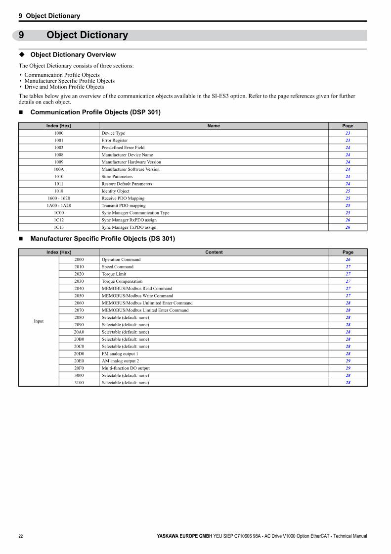
The Object Dictionary consists of three sections:
• Communication Profile Objects• Manufacturer Specific Profile Objects• Drive and Motion Profile Objects
The tables below give an overview of the communication objects available in the SI-ES3 option. Refer to the page references given for further details on each object.
Communication Profile Objects (DSP 301)
Manufacturer Specific Profile Objects (DS 301)
Index (Hex) Name Page
1000 Device Type 23
1001 Error Register 23
1003 Pre-defined Error Field 24
1008 Manufacturer Device Name 24
1009 Manufacturer Hardware Version 24
100A Manufacturer Software Version 24
1010 Store Parameters 24
1011 Restore Default Parameters 24
1018 Identity Object 25
1600 - 1628 Receive PDO Mapping 25
1A00 - 1A28 Transmit PDO mapping 25
1C00 Sync Manager Communication Type 25
1C12 Sync Manager RxPDO assign 26
1C13 Sync Manager TxPDO assign 26
Index (Hex) Content Page
Input
2000 Operation Command 26
2010 Speed Command 27
2020 Torque Limit 27
2030 Torque Compensation 27
2040 MEMOBUS/Modbus Read Command 27
2050 MEMOBUS/Modbus Write Command 27
2060 MEMOBUS/Modbus Unlimited Enter Command 28
2070 MEMOBUS/Modbus Limited Enter Command 28
2080 Selectable (default: none) 28
2090 Selectable (default: none) 28
20A0 Selectable (default: none) 28
20B0 Selectable (default: none) 28
20C0 Selectable (default: none) 28
20D0 FM analog output 1 28
20E0 AM analog output 2 29
20F0 Multi-function DO output 29
3000 Selectable (default: none) 28
3100 Selectable (default: none) 28
22 YASKAWA EUROPE GMBH YEU SIEP C710606 98A - AC Drive V1000 Option EtherCAT - Technical Manual

9 Object Dictionary
Drives and Motion Profile Objects (DSP 402)
Communication Profile Objects (DS 301)
1000 (Hex) - Device Type
This object describes the type of the device and its functionality. It is composed of a 16 bit field that describes the device profile used and a second 16 bit field that gives additional information about optional functionality.
Bit 0-15: Device Profile Number = 0x0192 (402) (static)
Bit 16-23: Type = x01 (static)
Bit 24-31: Mode Bits (Vendor specific) = 0x00
1001 (Hex) - Error Register
This register shows the fault status of the device. If any errors occurs in the device bit, 0 (generic error) is set to one.
0x00 = No error
0x01 = Generic error (INVR:0x00FE & 0x0080)
Output
2100 Drive Status 29
2110 Output Frequency 29
2120 Output Current 29
2130 Output Torque 30
2140 MEMOBUS/Modbus Read Command Response 30
2150 MEMOBUS/Modbus Write Command Response 30
2155 PDO Parameter Write Response 30
2160 MEMOBUS/Modbus Not Limited Enter Command Response 30
2180 Selectable (default: Input terminal status) 31
2190 Selectable (default: Analog input 1 monitor) 31
21A0 Selectable (default: none) 31
21B0 Selectable (default: none) 31
21C0 Selectable (default: none) 31
21E0 Selectable (default: none) 31
21D0 Selectable (default: none) 31
21F0 Selectable (default: none) 31
2200 Motor Speed 31
2210 DC Bus Voltage 31
2220 Analog input monitor A1 31
2240 Analog input monitor A2 32
2260 Analog input monitor A3 32
2270 Inverter DI Input 32
4000 Option NVS FATAL Record 32
4001 Option Info + Status Record 32
Object Type Index (Hex) Name Page
Common Entries60FD Digital Inputs 36
60FE Digital Outputs 36
Device Control
6040 Controlword 33
6041 Statusword 33
6060 Modes of operation 35
6061 Modes of operation display 36
Velocity Mode
6042 vl target velocity 33
6043 vl velocity demand 33
6044 vl control effort 33
6046 vl velocity min max amount 33
6048 vl velocity acceleration 34
6049 vl velocity deceleration 34
604A vl velocity quick stop 35
604C vl dimension factor 35
604D vl pole number 35
Index (Hex) Subindex Content Access PDO Mapping Value Range
1000 – Device type Read Only No Unsigned 32
Index (Hex) Subindex Content Access PDO Mapping Value Range
1001 – Error register Read Only Tx Unsigned 8
Index (Hex) Content Page
YASKAWA EUROPE GMBH YEU SIEP C710606 98A - AC Drive V1000 Option EtherCAT - Technical Manual 23

9 Object Dictionary
1003 (Hex) - Pre-defined Error Field
This register provides a history of errors that occurred in the drive and have been signalized via the Emergency object. Subindex 0 contains the number of errors. Subindexes 1 to FF contain a rolling list of error codes where subindex 1 always contains the last occurring error. Refer to EtherCAT® Option Card Error Codes on page 43 for a list of possible error codes. The number of valid logged errors in sub index is 0x01-0xFE.
Writing a 0 to subindex 0 resets the error field.
1008 (Hex) - Manufacturer Device Name
This object contains the manufacturer device name. String: EtherCAT® for 1000 series.
1009 (Hex) - Manufacturer Hardware Version
This object contains the manufacturer hardware version.
Value: 1.x
x = HW revision assigned during production
100A (Hex) - Manufacturer Software Version
This object contains the Manufacturer software version.
Value: VST92x101
YASKAWA Def: VST92x1zz
VST9 = V1000 option card
2 = European product
42 = Product code
zz = Minor revision
1010 (Hex) - Store Parameters
By writing "save" (s = 73H, a = 61H, v = 76H, e = 65H) to this object, the EtherCAT® Option settings are saved in the non-volatile memory. The EtherCAT® Option will operate using these settings when a Reset Node or Reset Communications command is performed or when the power supply is cycled.
Default read value: 0x01 (Save on command)
Actions: Write of value 0x0000 to INVR:0x0900; Will issue INV EEPROM enter command.
Note: Write access is only allowed in the EtherCAT® pre-operational state.
1011 (Hex) - Restore Default Parameters
Writing "load" (l = 6CH, o = 6FH, a = 61H, d = 64H) to this object restores the EtherCAT® Option default settings.
Default read value: 0x01 (Restore on command)
Actions: Option will write value=2220 to INVR:0x0103 (A1-03) together with an EEPROM ENTER command
Note: Write access is only allowed in the EtherCAT® pre-operational state.
Index (Hex) Subindex Content Access PDO Mapping Value Range
10030 Number of errors Read/Write
NoUnsigned 8
1 Standard error field Read Only Unsigned 32
Index (Hex) Subindex Content Access PDO Mapping Value Range
1008 – Manufacturer device name Read Only No Visible string
Index (Hex) Subindex Content Access PDO Mapping Value Range
1009 – Manufacturer hardware version Read Only No Visible string
Index (Hex) Subindex Content Access PDO Mapping Value Range
100A – Manufacturer software version Read Only No Visible string
Index (Hex) Subindex Content Access PDO Mapping Value Range
1010 1 Store parameters Read/Write No Unsigned 32
Index (Hex) Subindex Content Access PDO Mapping Value Range
1011 1 Restore default parameters Read/Write No Unsigned 32
24 YASKAWA EUROPE GMBH YEU SIEP C710606 98A - AC Drive V1000 Option EtherCAT - Technical Manual

9 Object Dictionary
1018 (Hex) - Identity Object
This object contains general information about the drive.
1600 (Hex) to 1628 (Hex) - Receive PDO mapping
1A00 (Hex) to 1A28 (Hex) - Transmit PDO mapping
1C00 (Hex) - Sync Manager Communication Type
Index (Hex) Subindex Content Access PDO Mapping Value Range
1018 - Identity object Read/Write - Unsigned 32
0 Number of entries Read Only No Unsigned 8
Value: 4
1 Vendor ID Read Only No Unsigned 32
YASKAWA ETG Member Vendor IDValue: 0x00000539 (Yaskawa Electric Corporation, Japan)
2 Product Code Read Only No Unsigned 32
EtherCAT® option product codeValue: 0x53455333 (ASCII: SES3)
3 Revision number Read Only No Unsigned 32
YASKAWA EtherCAT® option software revision number.Definition: xxxxxYYYY ' (xxxx=Major, YYYY=Minor)Value: 92x1.zz009 = V1000 option card2 = European product42= Product codezz= Minor revision
4 Serial number Read Only No Unsigned 32
EtherCAT® option serial number
Index (Hex) Subindex Content Access PDO Mapping Value Range
1600 - Receive PDO mapping - - -
0 Number of mapped application objects (0-8(2)) Read Write No Unsigned 8
Value: 0-8 (Depends on RxPDO)For default configurations per RxPDO please refer to section 3.9.1.Max Sub-index:0x1600: 80x1601-0x1628: 2Note: Write access to those objects are only allowed in the EtherCAT® pre-operational state.
1 Mapped Object #1 Read Write No Unsigned 32
2 Mapped Object #2 Read Write No Unsigned 32
3 Mapped Object #3 Read Write No Unsigned 32
n Mapped Object #n Read Write No Unsigned 32
Index (Hex) Subindex Content Access PDO Mapping Value Range
1A00 - Transmit PDO mapping - - -
0 Number of mapped application objects (0-8(2)) Read Write No Unsigned 8
Value: 0-8 (Depends on TxPDO)For default configurations per TxPDO please refer to section 3.9.2.Max Sub-index:0x1A00: 80x1A01-0x1A28: 2Note: Write access to those objects are only allowed in the EtherCAT® pre-operational state.
1 Mapped Object #1 Read Write No Unsigned 32
2 Mapped Object #2 Read Write No Unsigned 32
3 Mapped Object #3 Read Write No Unsigned 32
n Mapped Object #n Read Write No Unsigned 32
Index (Hex) Subindex Content Access PDO Mapping Value Range
1A00 - Transmit PDO mapping - - -
0 Number of entries Read Only No Unsigned 8
Value: 4
1 Mailbox wr Read Only No Unsigned 8
Value: 1
2 Mailbox rd Read Only No Unsigned 8
Value: 2
3 Process data out Read Only No Unsigned 8
Value: 3
4 Process data in Read Only No Unsigned 8
Value: 4
YASKAWA EUROPE GMBH YEU SIEP C710606 98A - AC Drive V1000 Option EtherCAT - Technical Manual 25

9 Object Dictionary
1C12 (Hex) - Sync Manager RxPDO assign
1C13 (Hex) - Sync Manager TxPDO assign
Manufacturer Specific Profile Objects (DS 301)
The SI-ES3 option offers the manufacturer specific objects listed below. These objects are specific to Yaskawa products and are therefore not available on other EtherCAT® products.
The manufacturer specific objects list consists of objects that have predefined, non-changeable content and objects that are configurable. The content of configurable objects can be determined by linking these objects to drive parameters, monitors or MEMOBUS/Modbus registers (refer to Selectable Object Content on page 37).
Input objects are processed in a cycle of 2 ms. Output objects are, depending on the object, updated in a cycle of either 2 ms or 8 ms. The update cycle cannot be changed.
2000 (Hex) - Operation Command
This object is used for starting and stopping the drive, for controlling the multi-function digital input terminals, as well for triggering and resetting faults.
Index (Hex) Subindex Content Access PDO Mapping Value Range
IC12 - Sync Manager RxPDO assign - - -
Sync Manager RxPDO assignment object.Note: Write access to this object is only allowed in the EtherCAT® pre-operational state.
0 Number of entries Read Write No Unsigned 8
Value: (0-4) Default: 1
1 Assigned RxPDO #1 Read Write No Unsigned 16
Default: 0x1600
2 Assigned RxPDO #2 Read Write No Unsigned 16
3 Assigned RxPDO #3 Read Write No Unsigned 16
4 Assigned RxPDO #4 Read Write No Unsigned 16
Index (Hex) Subindex Content Access PDO Mapping Value Range
IC12 - Sync Manager TxPDO assign - - -
Sync Manager TxPDO assignment object.Note: Write access to this object is only allowed in the EtherCAT® pre-operational state.
0 Number of entries Read Write No Unsigned 8
Value: (0-4) Default: 1
1 Assigned TxPDO #1 Read Write No Unsigned 16
Default: 0x1A00
2 Assigned TxPDO #2 Read Write No Unsigned 16
3 Assigned TxPDO #3 Read Write No Unsigned 16
4 Assigned TxPDO #4 Read Write No Unsigned 16
Index (Hex) Subindex Content Access PDO Mapping Data Length
2000
0 Operation Command Read/Write Possible
2 byte1 Value Read/Write Rx/Tx
2 MEMOBUS/Modbus register address Read Only No
Value: INVR:0x0001 (Run operation signal)
Bit No. (Hex) Description Function
0 Forward Run 1: Forward run, 0: Stop (Enabled when b1-02=3)
1 Reverse Run 1: Reverse run, 0: Stop (Enabled when b1-02=3)
2 Terminal S3 Function Multi-Function Input: H1-03
3 Terminal S4 Function Multi-Function Input: H1-04
4 Terminal S5 Function Multi-Function Input: H1-05
5 Terminal S6 Function Multi-Function Input: H1-06
6 Terminal S7 Function Multi-Function Input: H1-07
7 Terminal S8 Function Multi-Function Input: H1-08
8 External Fault (EF0) 1: External Fault Input (EF0)
9 Fault Reset 1: Fault Reset
10 to 15 Not used Not used
26 YASKAWA EUROPE GMBH YEU SIEP C710606 98A - AC Drive V1000 Option EtherCAT - Technical Manual

9 Object Dictionary
2010 (Hex) - Speed Reference/Speed Limit
Sets the speed reference or speed limit. The unit of this value depends on the setting of the drive parameter o1-03. The value will be used as the speed reference for speed control (d5-01 = 0) or as the speed limit in torque control (d5-01 = 1).
Note: The availability of the torque control function depends on the drive and the selected control mode. For details refer to the technical manual for the drive.
2020 (Hex) - Torque Reference/Torque Limit
This object sets the torque reference or the torque limit in units of 0.1%.In order to use this object set drive parameter F6-06 to 1. The value will be used as the torque reference for torque control (d5-01 = 1) or as the torque limit in speed control (d5-01 = 0).
Note: The availability of the torque control and torque limit function depends on the drive and the selected control mode. For details refer to the technical manual for the drive.
2030 (Hex) - Torque Compensation
This object sets the torque compensation in units of 0.1%.
2040 (Hex) - MEMOBUS/Modbus Read Request
This object can be used to read out the content of drive MEMOBUS/Modbus registers. The address of the MEMOBUS/Modbus must be written in byte 3 and 4 of Subindex 1, bytes 1 and 2 have to be set to 0. After sending a MEMOBUS/Modbus Read Request to the drive, the MEMOBUS/Modbus register content can be read out from object 2140H.
For more details on MEMOBUS/Modbus address and data, refer to the MEMOBUS/Modbus/Modbus Data Table in Appendix C of the technical manual for the drive.
2050 (Hex) - MEMOBUS/Modbus Write Request
Using this object, drive MEMOBUS/Modbus registers can be written. The data must be written in byte 1 and 2 of Subindex 1, the MEMOBUS/Modbus address must be written in bytes 3 and 4. After sending a MEMOBUS/Modbus Write Request to the drive, the response can be read from object 2150H.
For more details on MEMOBUS/Modbus address and data, refer to the MEMOBUS/Modbus Data Table in Appendix C of the technical manual for the drive.
Index (Hex) Subindex Content Access PDO Mapping Data Length
20100 Speed command Read/Write Possible 2 byte
1 Value Read/Write Rx/Tx -
Speed commandThe unit of this value depends on the setting of the drive parameter o1-03.o1-03:0: Hz1: % (100% = E1-04)2: rev/min (enter the number of motor poles into E2-04/E4-04/E5-04)3: User defined by parameters o1-10 and o1-11
- 2 MEMOBUS/Modbus register address Read Only No -
Value: INVR:0x0002 (Frequency reference)
Index (Hex) Subindex Content Access PDO Mapping Data Length
2020
0 Torque Reference/Limit Read/Write Possible 2 byte
1 Value Read/Write Rx Tx -
2 MEMOBUS/Modbus register address Read Only No -
Value: INVR:0x0004 (Torque ref/limit)
Index (Hex) Subindex Content Access PDO Mapping Data Length
2030
0 Torque Compensation Read/Write Possible 2 byte
1 Value Read/Write Rx Tx -
2 MEMOBUS/Modbus register address Read Only No -
Value: INVR:0x0005 (Torque compensation)
Index (Hex) Subindex Content Access PDO Mapping Data Length
2040
0 Number of entries Read Only
Possible
1 byte
1 MEMOBUS/Modbus read request Read/Write2 + 2 byte
MEMOBUS/Modbus0000H + Address
Value: 0xAAAABBBB -> 0xAAAA = drive register, 0xBBBB = 0x0000
Index (Hex.) Subindex Content Access PDO Mapping Data Length
2050
0 Number of entries Read Only
Possible
1 byte
1 MEMOBUS/Modbus Write request Read/Write2 + 2 byte
MEMOBUS/ModbusData + Address
Value: 0xAAAABBBB -> 0xAAAA = drive register, 0xBBBB = 0x0000
YASKAWA EUROPE GMBH YEU SIEP C710606 98A - AC Drive V1000 Option EtherCAT - Technical Manual 27
9 Object Dictionary
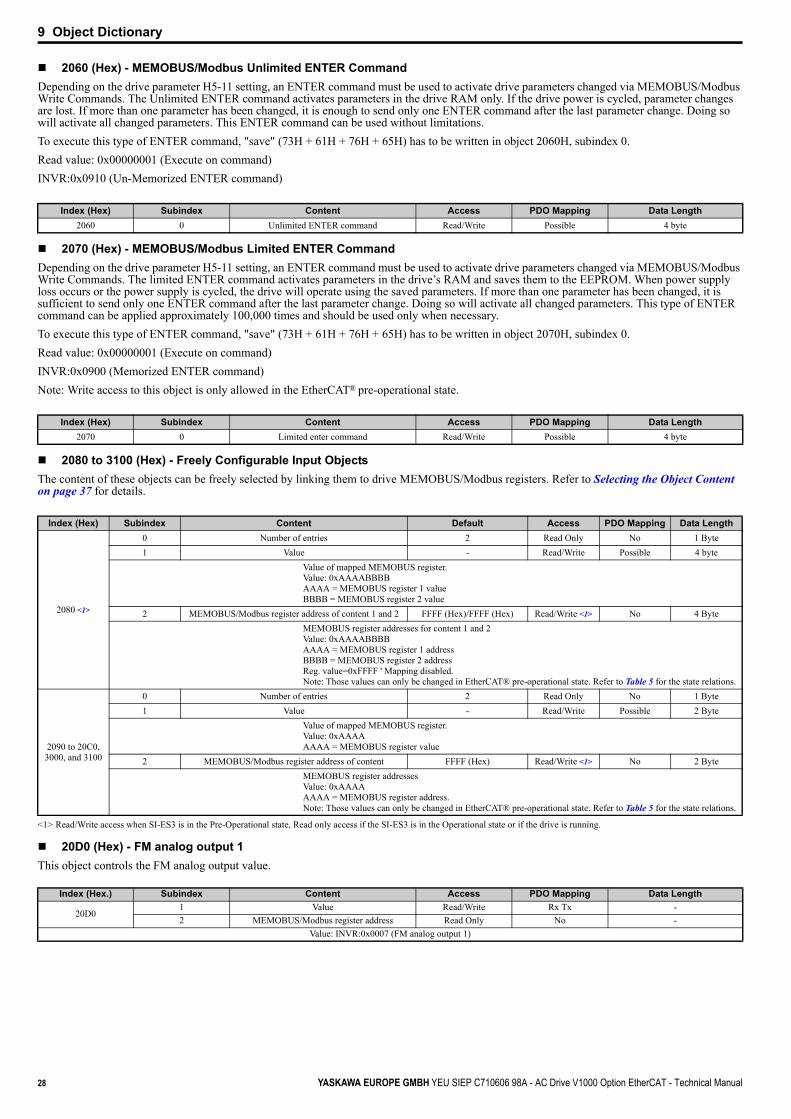
2060 (Hex) - MEMOBUS/Modbus Unlimited ENTER Command
Depending on the drive parameter H5-11 setting, an ENTER command must be used to activate drive parameters changed via MEMOBUS/Modbus Write Commands. The Unlimited ENTER command activates parameters in the drive RAM only. If the drive power is cycled, parameter changes are lost. If more than one parameter has been changed, it is enough to send only one ENTER command after the last parameter change. Doing so will activate all changed parameters. This ENTER command can be used without limitations.
To execute this type of ENTER command, "save" (73H + 61H + 76H + 65H) has to be written in object 2060H, subindex 0.
Read value: 0x00000001 (Execute on command)
INVR:0x0910 (Un-Memorized ENTER command)
2070 (Hex) - MEMOBUS/Modbus Limited ENTER Command
Depending on the drive parameter H5-11 setting, an ENTER command must be used to activate drive parameters changed via MEMOBUS/Modbus Write Commands. The limited ENTER command activates parameters in the drive’s RAM and saves them to the EEPROM. When power supply loss occurs or the power supply is cycled, the drive will operate using the saved parameters. If more than one parameter has been changed, it is sufficient to send only one ENTER command after the last parameter change. Doing so will activate all changed parameters. This type of ENTER command can be applied approximately 100,000 times and should be used only when necessary.
To execute this type of ENTER command, "save" (73H + 61H + 76H + 65H) has to be written in object 2070H, subindex 0.
Read value: 0x00000001 (Execute on command)
INVR:0x0900 (Memorized ENTER command)
Note: Write access to this object is only allowed in the EtherCAT® pre-operational state.
2080 to 3100 (Hex) - Freely Configurable Input Objects
The content of these objects can be freely selected by linking them to drive MEMOBUS/Modbus registers. Refer to Selecting the Object Content on page 37 for details.
20D0 (Hex) - FM analog output 1
This object controls the FM analog output value.
Index (Hex) Subindex Content Access PDO Mapping Data Length
2060 0 Unlimited ENTER command Read/Write Possible 4 byte
Index (Hex) Subindex Content Access PDO Mapping Data Length
2070 0 Limited enter command Read/Write Possible 4 byte
Index (Hex)
<1> Read/Write access when SI-ES3 is in the Pre-Operational state, Read only access if the SI-ES3 is in the Operational state or if the drive is running.
Subindex Content Default Access PDO Mapping Data Length
2080 <1>
0 Number of entries 2 Read Only No 1 Byte
1 Value - Read/Write Possible 4 byte
Value of mapped MEMOBUS register.Value: 0xAAAABBBBAAAA = MEMOBUS register 1 valueBBBB = MEMOBUS register 2 value
2 MEMOBUS/Modbus register address of content 1 and 2 FFFF (Hex)/FFFF (Hex) Read/Write <1> No 4 Byte
MEMOBUS register addresses for content 1 and 2Value: 0xAAAABBBBAAAA = MEMOBUS register 1 addressBBBB = MEMOBUS register 2 addressReg. value=0xFFFF ' Mapping disabled.Note: Those values can only be changed in EtherCAT® pre-operational state. Refer to Table 5 for the state relations.
2090 to 20C0, 3000, and 3100
0 Number of entries 2 Read Only No 1 Byte
1 Value - Read/Write Possible 2 Byte
Value of mapped MEMOBUS register.Value: 0xAAAAAAAA = MEMOBUS register value
2 MEMOBUS/Modbus register address of content FFFF (Hex) Read/Write <1> No 2 Byte
MEMOBUS register addressesValue: 0xAAAAAAAA = MEMOBUS register address.Note: Those values can only be changed in EtherCAT® pre-operational state. Refer to Table 5 for the state relations.
Index (Hex.) Subindex Content Access PDO Mapping Data Length
20D01 Value Read/Write Rx Tx -
2 MEMOBUS/Modbus register address Read Only No -
Value: INVR:0x0007 (FM analog output 1)
28 YASKAWA EUROPE GMBH YEU SIEP C710606 98A - AC Drive V1000 Option EtherCAT - Technical Manual

9 Object Dictionary
20E0 (Hex) - AM analog output 2
This object controls the AM analog output value.
20F0 (Hex) - Multi-function DO output
This object controls the multi-function DO outputs.
2100 (Hex)/2101 (Hex) - Drive Status
These objects can be used to monitor the drive status. The value in object 2100 (Hex) is not filtered.
2110 (Hex) - Output Frequency
This object can be used to monitor the drive output frequency. The unit of the monitor value is determined by drive parameter o1-03.
0: Hz
1: % (100% = E1-04)
2: r/min (enter the number of motor poles into E2-04/E4-04/E5-04)
3: User defined by parameters o1-10 and o1-11
2120 (Hex) - Output Current
This object can be used to monitor the drive output current in units of Ampere. The current value resolution is the same as in drive monitor U1-03 (for details refer to the technical manual of the drive).
Index (Hex.) Subindex Content Access PDO Mapping Data Length
20E01 Value Read/Write Rx Tx -
2 MEMOBUS/Modbus register address Read Only No -
Value: INVR:0x0008 (AM analog output 2)
Index (Hex.) Subindex Content Access PDO Mapping Data Length
20F01 Value Read/Write Rx Tx -
2 MEMOBUS/Modbus register address Read Only No -
Value: INVR:0x0009 (Multi-function DO)
Index (Hex) Subindex Content Default Access PDO Mapping Data Length Update Cycle
2100
0 Drive Status - Read Only Possible 2 byte 2 ms
1 Value - Read Only Tx 2 byte 2 ms
2 MEMOBUS/Modbus register address 00FC (Hex) Read Only No 2 byte -
Value: INVR:0x00FC (Drive status)
Bit No. (Hex) Function Description
0 During Run 1: During Run 0: During Stop
1 During Zero Speed 1: During Zero Speed
2 Reverse Running 1: During Reverse Running 0: During Forward Running
3 During Fault Reset Signal Input 1: During Fault Reset Signal Input
4 During Speed Agree 1: During Speed Agree
5 During Drive Ready 1: During Drive Ready 0: Not Ready
6 During Alarm 1: During Alarm
7 During Fault 1: During Fault
8 During Operation Error 1: During Operation Error
9 During Momentary Power Loss 1: During Momentary Power Loss 0: During Power Loss
A NetCtrl Status 1: NetCtrl
B Digital Output 1 Status (function set in drive parameter H2-01) 1: ON 0: OFF
C Digital Output 2 Status (function set in drive parameter H2-02) 1: ON 0: OFF
D Digital Output 3 Status (function set in drive parameter H2-03) 1: ON 0: OFF
E Motor 2 Selected 1: Motor 2 Selected
F Zero-Servo End 1: Zero-Servo End
Index (Hex) Subindex Content Default Access PDO Mapping Data Length Update Cycle
2110
- Output Frequency - Read Only - -
1 Value - Read Only Tx Unsigned 16
2 MEMOBUS/Modbus register address 0041 (Hex) Read Only No Unsigned 16
Value: INVR:0x0041, U1-02 (Output frequency)
Index (Hex) Subindex Content Default Access PDO Mapping Value Range
2120
- Output Current - Read Only - -
1 Value - Read Only Tx Unsigned 16
2 MEMOBUS/Modbus register address 00FB (Hex) Read Only No Unsigned 16
Value: INVR:0x00FB (Output current)
YASKAWA EUROPE GMBH YEU SIEP C710606 98A - AC Drive V1000 Option EtherCAT - Technical Manual 29

9 Object Dictionary
2130 (Hex) - Output Torque Reference
This object can be used to monitor the output torque reference.
The availability of this object content depends on the drive control mode. If the selected control mode does not support this monitor (equal to drive monitor U1-09), the torque reference monitor value will be 0. Refer to the drive technical manual for details.
2140 (Hex) - MEMOBUS/Modbus Read Response
This object contains the data of the drive MEMOBUS/Modbus register specified in object 2040 (Hex). Bytes 1 and 2 of subindex 1 will contain the data, bytes 3 and 4 will contain the MEMOBUS/Modbus Address read.
0xAAAABBBB ->
0xAAAA = drive register
0xBBBB = Data
2150 (Hex) - MEMOBUS/Modbus Write Response
This object contains the response from the drive when writing a drive parameter using a MEMOBUS/Modbus write command (object 2050 (Hex)). Bytes 1 and 2 of subindex 1 will contain the data that were written, bytes 3 and 4 will contain the MEMOBUS/Modbus Address that was written to.
Value:
0xAAAABBBB ->
0xAAAA = drive register
0xBBBB = Data
2155 (Hex) - PDO Parameter Write ResponseNote: Object only available in EtherCAT® SAFE_OP or OPERATIONAL state. Object data is always cleared when a transition from PRE_OP ' SAFE_ OP is done.
This object contains the response from the drive when writing a drive parameter directly using a RxPDO. Byte 1 and 2 contain the last RxPDO number that caused the error. Byte 3 contains the number of errors. The error counter is increased when an NOID Online-DRV control data write is flagged as invalid by the drive (INVSTS2: Bit6, Control command error or local option RxPDO error). This object can only be read if the SI-ES3 option is in Operational state.
2160 (Hex) - MEMOBUS/Modbus Not Limited Enter Command Response
This object contains the response from the drive when writing an Enter command using object 2060 (Hex).
Response values:
OK: 0x65766173
ERR: MEMOBUS error code or SDO abort code if SDO request.
Index (Hex) Subindex Content Default Access PDO Mapping Value Range
2130
- Output Torque Reference - Read Only - -
1 Value - Read Only Tx Unsigned 16
2 MEMOBUS/Modbus register address 0048 (Hex) Read Only No Unsigned 16
Value: INVR:0x0048 (Output torque reference)
Index (Hex) Subindex Content Access PDO Mapping Value Range
2140
0 Number of entries Read Only No Unsigned 8
Value: 0x01
1 MEMOBUS/Modbus read response Read Only Tx Unsigned 32
Index (Hex) Subindex Content Access PDO Mapping Value Range
2150
0 Number of entries Read Only No Unsigned 8
Value: 0x01
1 MEMOBUS write response Tx Unsigned 32
Index (Hex) Subindex Content Access PDO Mapping Data Length
2155 0 PDO Parameter Write Response Read Only Tx 3 byte
Index (Hex) Subindex Content Access PDO Mapping Data Length
2160 0MEMOBUS/Modbus not limited enter command
responseRead Only Tx 4 byte
30 YASKAWA EUROPE GMBH YEU SIEP C710606 98A - AC Drive V1000 Option EtherCAT - Technical Manual

9 Object Dictionary
2180 (Hex) to 21E0 (Hex) - Configurable Output ObjectsNote: This value can only be changed in EtherCAT® pre-operational state.
The content of these objects can be selected by linking them to drive MEMOBUS/Modbus registers.
21F0 (Hex) - Configurable Output ObjectNote: This value can only be changed in EtherCAT® pre-operational state.
The content of this object can be selected by linking them to drive MEMOBUS/Modbus registers.
2200 (Hex) - Motor Speed
This object can be used to monitor the motor speed. The value in object 2200 (Hex) is not filtered. Setting units are determined by o1-03.
The availability of the object content depends on the drive control mode. If the selected control mode does not support this monitor (equal to drive monitor U1-05), the object value will be 0. Refer to the drive technical manual for details.
2210 (Hex) - DC Bus voltage
This object can be used to monitor the DC BUS voltage.
2220 (Hex) - Analog Input Monitor A1
This object can be used to display the analog input A1 level: 100% when input is 10 V.
Index (Hex) Subindex Content Default Access PDO Mapping Data Length
2180 to 21E0
0 Number of entries - Read Only No Unsigned 8
1 Value of mapped drive register - Read Only Tx Unsigned 16
2 MEMOBUS/Modbus register address of content
Defaults:0x2180: 0x0049 (Input Terminal Status)0x2190: 0x004E (Analog Input A1 Monitor)0x21A0-0x21E0: Default: 0xFFFF (No mapping)
Read/Write No Unsigned 16
Index (Hex) Subindex Content Default Access PDO Mapping Data Length
21F0
0 Number of entries - Read Only No Unsigned 8
1 Value of mapped drive register 1 and 2 - Read Only Tx Unsigned 32
Value: 0xAAAABBBB ->AAAA = MEMOBUS register 1 valueBBBB = MEMOBUS register 2 value
2 MEMOBUS register address of content 1 and 2
Value: 0xAAAABBBB ' AAAA = MEMOBUS register 1 addressBBBB = MEMOBUS register 2 addressReg. value=0xFFFF ' Mapping disabled.Default: 0xFFFFFFFF
Read/Write No Unsigned 32
Index (Hex) Subindex Content Default Access PDO Mapping Data Length
2200
- Motor Speed - Read Only - -
0 Number of Entries - Read Only No Unsigned 8
1 Motor Speed - Read Only Tx Unsigned 16
2 MEMOBUS/Modbus register address of content 0044 (Hex) Read Only No Unsigned 16
Value: INVR:0x0044 (Motor speed)
Index (Hex) Subindex Content Default Access PDO Mapping Data Length
2210
- DC Bus voltage - Read Only - -
1 Value 1 V Read Only Tx Unsigned 16
2 MEMOBUS/Modbus register address of content 0046 (Hex) Read Only No Unsigned 16
Value: INVR:0x0046 (DC Bus voltage)
Index (Hex) Subindex Content Default Access PDO Mapping Data Length
2220
- Analog input monitor A1 - Read Only - -
1 Value 0.1 % Read Only Tx Unsigned 16
2 MEMOBUS/Modbus register address of content 004E (Hex) Read Only No Unsigned 16
Value: INVR:0x004E (Terminal A1 Input Level)
YASKAWA EUROPE GMBH YEU SIEP C710606 98A - AC Drive V1000 Option EtherCAT - Technical Manual 31

9 Object Dictionary
2240 (Hex) - Analog Input Monitor A2
This object can be used to display the analog input A2 level: 100% when input is 10 V.
2260 (Hex) - Analog Input Monitor A3
This object can be used to display the analog input A3 level: 100% when input is 10 V.
2270 (Hex) - Drive DI Input
This object can be used to display the input terminal status.
4000 (Hex) - Option NVS FATAL Record
Internal FATAL NVS record for debugging purposes.
Note: Writing 0xFB to sub-index 0 will clear the record in NVS memory.
4001 (Hex) - Option Info + Status Record
Provides general information of option system firmware parts and internal system states.
Index (Hex) Subindex Content Default Access PDO Mapping Data Length
2240
- Analog input monitor A2 - Read Only - -
1 Value 0.1 % Read Only Tx Unsigned 16
2 MEMOBUS/Modbus register address of content 004F (Hex) Read Only No Unsigned 16
Value: INVR:0x004F (Terminal A2 Input Level)
Index (Hex) Subindex Content Default Access PDO Mapping Data Length
2260
- Analog input monitor A3 - Read Only - -
1 Value 0.1 % Read Only Tx Unsigned 16
2 MEMOBUS/Modbus register address of content 0050 (Hex) Read Only No Unsigned 16
Value: INVR:0x0050 (Terminal A3 Input Level)
Index (Hex) Subindex Content Default Access PDO Mapping Data Length
2270
- Drive DI Input - Read Only - -
1 Value - Read Only Tx Unsigned 16
2 MEMOBUS/Modbus register address of content 0049 (Hex) Read Only No Unsigned 16
Value: INVR:0x0049 (Input Terminal Status)
Index (Hex) Subindex Content Default Access PDO Mapping Data Length
4001
- Option NVS FATAL Record - Read/Write No Unsigned 8
Information regarding a system failure/crash is stored in this object and can be read out for on-site troubleshooting.
1 Number of FATALs - Read Only No Unsigned 16
Total number of FATAL events logged since entry was cleared.
Index (Hex) Subindex Content Default Access PDO Mapping Data Length
4001
- Option Info+Status Record - Read Only No Unsigned 8
Provides general information of option system firmware parts and internal system states.
1 OptBootFwRev - Read Only No Unsigned 32
Boot firmware revision in flash.Value: 0x00AABBCCAA = Major revisionBB = Minor revisionCC = Build
2 OptAppFwRev - Read Only No Unsigned 32
Application firmware revision in flash.Value: 0x00AABBCCAA = Major revisionBB = Minor revisionCC = Build
3 OptRunTimeMS - Read Only No Unsigned 32
Total running time in milliseconds of option system since power-up.
4 NOISystem: iSysErrorBits - Read Only No Unsigned 16
NOI System active error bits.
5 NOISystem: iSysErrorBitsLatched - Read Only No Unsigned 16
NOI System latched (All errors that have occurred since start-up) error bits.
32 YASKAWA EUROPE GMBH YEU SIEP C710606 98A - AC Drive V1000 Option EtherCAT - Technical Manual

9 Object Dictionary
Drives and Motion Profile Objects (DSP 402)
The drive supports the Drive and Motion Profile DSP 402 Velocity Mode. Before using the Velocity Mode objects the following parameters have to be set up in the drive:
• The number of motor poles must be set to E2-04.• The frequency reference and output frequency display unit must be set to r/min by setting parameter o1-03 = 2.
If these settings are not done properly, the Velocity Mode objects can not be used or the drive might not operate as expected.
Note: Drive and Motion Control (DSP 402) cannot be set or referenced unless o1-03 = 2.
6040 (Hex) - Controlword
This object sets the device to different states.
6041 (Hex) - Statusword
This object shows different states of the device.
6042 (Hex) - vl Target Velocity
This object sets the speed reference and the run command. It is internally multiplied with the vl dimension factor (604C). Can be set when the status in Control word 6040 (Hex) is “Operation Enable”.
INVR:0x0010 (Reference frequency in rpm)
If vl target velocity is < 0 value will be converted to positive before writing it to INVR:0x0010. Also 0x6040 ENABLE_OP command will be processed as RUN REV order.
If target velocity >= 0 value will be used natively in INVR:0x0010 and 0x6040 ENABLE_OP command will be processed as RUN FWD order.
6043 (Hex) - vl Velocity Demand
The vl velocity effort is the output frequency of the drive to the motor.
INVR:0x003E (Output frequency in rpm)
If (INVR:0x00FC#0x0004 = 1) value in INVR:0x003E will be turned to negative to indicate REV operation mode.
6044 (Hex) - vl Velocity Control Effort/Actual Value
The V1 control effort is the motor speed.
INVR:0x00AC (Motor speed in rpm)
If (INVR:0x00FC#0x0004 = 1) value in INVR:0x00AC will be turned to negative to indicate REV operation mode.
6046 (Hex) - vl Velocity Min Max Amount
This object provides two subindexes to set the minimum and maximum speed reference in r/min.
Index (Hex) Subindex Content Access PDO Mapping Value Range
6040 0 Controlword Read/Write Rx/Tx 0...65535
Index (Hex) Subindex Content Access PDO Mapping Value Range
6041 0 Statusword Read Only Tx 0...65535
Index (Hex) Subindex Content Access PDO Mapping Value Range Unit
6042 0 vl target velocity Read/Write Rx /Tx -32768...0...32767 r/min
Index (Hex) Subindex Content Access PDO Mapping Value Range Unit
6043 0 vl velocity demand Read Only Tx -32768...0...32767 r/min
Index (Hex) Subindex Content Access PDO Mapping Value Range Unit
6044 0 vl control effort Read Only Tx -32768...0...32767 r/min
Index (Hex) Subindex Content Access PDO Mapping Value Range Unit
6046
1 vl velocity min amount Read/Write Rx/Tx 0...(232-1) r/min
Minimum speed reference allowedINVR:0x028A, d2-02 (Frequency reference lower limit)Note: The parameter specifies the % rate of E1-04 maximum output frequency. Internal parameter calculations needed.
2 vl velocity max amount Read/Write Rx/Tx 0...(232-1) r/min
Maximum speed reference allowedINVR:0x0289, d2-01 (Frequency reference upper limit)Note: The parameter specifies the % rate of E1-04 maximum output frequency. Internal parameter calculations needed.
YASKAWA EUROPE GMBH YEU SIEP C710606 98A - AC Drive V1000 Option EtherCAT - Technical Manual 33

9 Object Dictionary
6048 (Hex) - vl Velocity Acceleration
The vl velocity acceleration specifies the acceleration time. The quotient of the subindexes delta speed and delta time determines the acceleration time. The object values correspond to the acceleration time setting in the drive.
Behavior: At power-up option will sync the E1-04 (Max output frequency) against the delta speed (sub-index 1) and calculate the delta time (sub-index 2) accordingly. If the E1-04 (Max output frequency) changes during runtime the option will adapt the internal delta speed attribute according the change of E1-04 linearly to provide the proper delta-speed.
6049 (Hex) - vl Velocity Deceleration
The vl velocity min max amount specifies the deceleration time. The quotient of the subindexes delta speed and delta time determines the deceleration time. The object values correspond to the deceleration time setting in the drive.
Behavior: At power-up option will sync the E1-04 (Max output frequency) against the delta speed (sub-index 1) and calculate the delta time (sub-index 2) accordingly. If the E1-04 (Max output frequency) changes during runtime the option will adapt the internal delta speed attribute according the change of E1-04 linearly to provide the proper delta-speed.
Index (Hex) Subindex Content Access PDO Mapping Value Range Unit
6048
1 Acceleration Delta speed Read/Write Rx/Tx 0...(223 -1) r/min
T = INVR:0x0200, C1-01(Unit: 0.1/0.01s) (Acceleration time 1)M = INVR:0x0303, E1-04 (Unit:0.1Hz) (Max output frequency)P = INVR:0x0211, E2-04 (Motor pole count)Mrpm = (120*M)/Pdt =Delta time, sub-index 2Delta speed(ds) = Mrpm (At power-up)T=(dt*M)/dsNote: Unit of T (C1-01) is linked to C1-10
2 Acceleration Delta time Read/Write Rx/Tx 0...65535 sec
T = INVR:0x0200, C1-01(Unit: 0.1/0.01s) (Acceleration time 1)M = INVR:0x0303, E1-04 (Unit:0.1Hz) (Max output frequency)P = INVR:0x0211, E2-04 (Motor pole count)Mrpm = (120*M)/Pds = Delta speed, Sub-index 1Delta time(dt) = (ds*T)/Mrpm(dt)T=(dt*M)/dsNote: Unit of T (C1-01) is linked to C1-10
Index (Hex) Subindex Content Access PDO Mapping Value Range Unit
6049
1 Deceleration Delta speed Read/Write Rx/Tx 0...(223 -1) r/min
T = INVR:0x0201, C1-02(Unit: 0.1/0.01s) (Deceleration time 1)M = INVR:0x0303, E1-04 (Unit:0.1Hz) (Max output frequency)P = INVR:0x0211, E2-04 (Motor pole count)Mrpm = (120*M)/Pdt =Delta time, sub-index 2Delta speed(ds) = Mrpm (At power-up)T=(dt*M)/dsNote: Unit of T (C1-01) is linked to C1-10
2 Deceleration Delta time Read/Write Rx/Tx 0...65535 sec
T = INVR:0x0201, C1-02(Unit: 0.1/0.01s) (Deceleration time 1)M = INVR:0x0303, E1-04 (Unit:0.1Hz) (Max output frequency)P = INVR:0x0211, E2-04 (Motor pole count)Mrpm = (120*M)/Pds = Delta speed, Sub-index 1Delta time(dt) = (ds*T)/Mrpm(dt)T=(dt*M)/dsNote: Unit of T (C1-01) is linked to C1-10
34 YASKAWA EUROPE GMBH YEU SIEP C710606 98A - AC Drive V1000 Option EtherCAT - Technical Manual

9 Object Dictionary
604A Hex) - vl Velocity Quick Stop
The vl velocity quick stop specifies the quick stop ramp. The quotient of the subindexes delta speed and delta time determines the quick stop ramp time. The object values correspond to the fast stop time setting in the drive.
Behavior: At power-up option will sync the E1-04 (Max output frequency) against the delta speed (sub-index 1) and calculate the delta time (sub-index 2) accordingly. If the E1-04 (Max output frequency) changes during runtime the option will adapt the internal delta speed attribute according the change of E1-04 linearly to provide the proper delta-speed.
604C (Hex) - vl Dimension Factor
The vl dimension factor is multiplied with the target velocity. The quotient of the subindexes vl dimension factor numerator and vl dimension factor denominator determines the vl dimension factor.
Default Value = 1
This parameter affects other objects such as:
0x6042 vl_target_velocity,
0x6043 vl_velocity_demand.
0x6044 vl_control_effort
0x6046 vl_velocity_min_max_amount.
0x6048 vl_velocity_acceleration
0x6049 vl_velocity_deceleration
0x604A vl_velocity_quick_stop.
and is always used in a product (multiplication).
604D (Hex) - vl Pole Number
The vl pole number sets the number of motor poles and is used to calculate all speed related values in r/min. This value corresponds to the number of motor poles setting in the drive.
INVR:0x0311, E2-04 (Number of motor poles)
6060 (Hex) - Modes of Operation
This object sets the mode of the device. The object supports 2 (Velocity Mode) only.
Value: 2: Velocity mode.
Index (Hex) Subindex Content Access PDO Mapping Value Range Unit
604A
1 Quick Stop Delta speed Read/Write Rx/Tx 0...(223 -1) r/min
T = INVR:0x0208, C1-09(Unit: 0.1/0.01s) (Fast stop time)M = INVR:0x0303, E1-04 (Unit:0.1Hz) (Max output frequency)P = INVR:0x0211, E2-04 (Motor pole count)Mrpm = (120*M)/Pdt =Delta time, sub-index 2Delta speed(ds) = Mrpm (At power-up)T=(dt*M)/dsNote: Unit of T (C1-01) is linked to C1-10
2 Quick Stop Delta time Read/Write Rx/Tx 0...65535 sec
T = INVR:0x0208, C1-09(Unit: 0.1/0.01s) (Fast stop time)M = INVR:0x0303, E1-04 (Unit:0.1Hz) (Max output frequency)P = INVR:0x0211, E2-04 (Motor pole count)Mrpm = (120*M)/Pds = Delta speed, Sub-index 1Delta time(dt) = (ds*T)/Mrpm(dt)T=(dt*M)/dsNote: Unit of T (C1-01) is linked to C1-10
Index (Hex) Subindex Content Access PDO Mapping Value Range
604C
1 vl dimension factor numerator Read/Write Rx/Tx -231...(231-1)
Internal in EtherCAT® option card, save in NVS memory.Default Value = 1.
2 vl dimension factor denominator Read/Write Rx/Tx -231...(231-1)
Internal in EtherCAT® option card, save in NVS memory.Default Value = 1
Index (Hex) Subindex Content Access PDO Mapping Value Range
604D 0 vl pole number Read/Write Tx 0...255
Index (Hex) Subindex Content Access PDO Mapping Value Range
6060 0 Modes of Operation Read/Write Rx/Tx -128...127
YASKAWA EUROPE GMBH YEU SIEP C710606 98A - AC Drive V1000 Option EtherCAT - Technical Manual 35

9 Object Dictionary
6061 (Hex) - Modes of Operation Display
This object shows the mode of the device. The object supports 2 (Velocity Mode) only.
Value: 2: Velocity mode.
Value: -2: Vendor control mode.
60FD (Hex) - Digital Inputs
This object contains the drive digital output status (seen as input to the network).
The content of this object is equal to drive MEMOBUS/Modbus register 004A (Hex) (drive output terminal status monitor U1-11) and depends on the drive the SI-ES3 option card is used with. For details on the content of this register refer to the technical manual for the drive.
Bit defines:
0-15 = reserved (Set to zero)
16-31 = INVR:0x004A, U1-11 (Output terminal status)
60FE (Hex) - Digital Outputs
This object is used to set drive digital inputs (seen as output from the network).
Index (Hex) Subindex Content Access PDO Mapping Value Range
6061 0 Modes of Operation Display Read Only Tx -128...127
Index (Hex) Subindex Content Access PDO Mapping Value Range
60FD 0 Drive digital input status Read Only Tx 0...(232-1)
Bit No. (Hex) Function Description
0 to F Reserved
10 to 1F Bit 0 to F of drive register 004A (Hex) (drive output terminal status monitor U1-11) 1: ON 0: OFF
Index (Hex) Subindex Content Access PDO Mapping Value Range
60FE - Drive Digital Input Command Read/Write - -
0 Number of elements Read Only - 0...255
1 Physical Outputs Read/Write Rx/Tx 0...(232-1)
Bit No. (Hex) Function Description
0 to 17 Reserved (Set to zero)
18 Terminal S3 Function INVR:0x0001#0x0040 (1=set, 0=clear)
19 Terminal S4 Function INVR:0x0001#0x0080 (1=set, 0=clear)
20 Terminal S5 Function INVR:0x0001#0x0100 (1=set, 0=clear)
21 Terminal S6 Function INVR:0x0001#0x0200 (1=set, 0=clear)
22 Terminal S7 Function INVR:0x0001#0x0400 (1=set, 0=clear)
23 Terminal S8 Function INVR:0x0001#0x0800 (1=set, 0=clear)
24 External Fault (EF0) INVR:0x0001#0x0004 (1=set, 0=clear)
25 Fault Reset INVR:0x0001#0x0008 (1=set, 0=clear)
26 to 31 Reserved (Set to zero)
36 YASKAWA EUROPE GMBH YEU SIEP C710606 98A - AC Drive V1000 Option EtherCAT - Technical Manual

10 Configuring Manufacturer Specific CANopen Objects
10 Configuring Manufacturer Specific CANopen ObjectsThis section describes the configuration of manufacturer specific objects that support content selection.
Selectable Object Content
All parameters, monitors and other control registers in the drive are represented by their MEMOBUS/Modbus register. The EtherCAT® option card allows the user to select the content of some manufacturer specific objects by mapping them to any of the drives MEMOBUS registers, so that those objects can be set up to contain the value of drive parameters, monitors as well as other MEMOBUS/Modbus registers (e.g. alarm and fault status, etc.). Refer to the drive Technical Manual for details on available MEMOBUS/Modbus registers.
Selecting the Object Content
Objects with selectable content have the following structure.
To map the content of a certain MEMOBUS/Modbus register of the drive to subindex 1 of an object, the MEMOBUS/Modbus register address must be written to subindex 2 of the object.
Examples• In order to map the drive output power monitor (U1-08, 0047 (Hex)) to output object 21A0 (Hex), write 0047 (Hex) to subindex 2 of object 21A0
(Hex).• In order to map the speed reference 1 (d1-01, 0280 (Hex)) to input object 2090 (Hex), write 0280 (Hex) to subindex 2 of object 2090 (Hex).• In order to map the input terminal status (U1-10, 0049 (Hex)) and output terminal status (U1-11, 004A (Hex)) to output object 21F0 (Hex) (4
Byte), write 0049 (Hex) to the higher and 004A (Hex) to the lower word of object 2090 (Hex), subindex 2.
Limitations of Object Content Selection
The following limitations have to be considered when setting the content of an object.
• The object content can only be changed when the SI-ES3 option card is in Pre-Operational state and drive is stopped (Run command not active).• The SI-ES3 can not be switched to the Operational state until the content selection process is complete. Otherwise, an emergency message (code
6301 (Hex)) will be sent.• When object content selection is ongoing, no other request or command, including Run, should be sent to the drive. Otherwise, an error message
or an emergency message (code 6301 (Hex)) will be sent.• For 4 byte input objects, MEMOBUS/Modbus register numbers below 0100 (Hex) can be linked in any combination. If MEMOBUS/Modbus
register numbers above 00FF (Hex) are linked to a 4 byte object, the MEMOBUS/Modbus register numbers must be consecutive.
• Register numbers must not be consecutive for 4 Byte output objects.• A MEMOBUS/Modbus register can no be mapped to two or more objects at the same time.• MEMOBUS/Modbus registers 0001 (Hex), 0002 (Hex), 0004 (Hex), 0005 (Hex), 0007 (Hex), 0008 (Hex), 0009 (Hex), and 0014 (Hex) are
already linked to not changeable input objects and can not be linked to any object with selectable content. Trying to map one of those registers to an input object will result in an error message.
Object Type Subindex
<1> Read/Write access when SI-ES3 is in the Pre-Operational state, Read only access if the SI-ES3 is in the Operational state or if the drive is running.
Content Access PDO Mapping Data Length
2 Byte
0 Number of entries Read Only No 1 byte
1 Data depends on object Possible 2 byte
2 MEMOBUS/Modbus register address Read/Write <1> No 2 byte
4 Byte
0 Number of entries Read Only No 1 byte
1 Data depends on object Possible 4 byte
2 MEMOBUS/Modbus register address 1 and 2 Read/Write <1> No 4 byte
Mapped Register 1 Mapped Register 2
0007 (Hex) 0009 (Hex) Possible
0201 (Hex) 0202 (Hex) Possible
0202 (Hex) 0201 (Hex) Not possible
0201 (Hex) 0203 (Hex) Not possible
0202 (Hex) 0202 (Hex) Not possible
0200 (Hex) FFFF (Hex) (Disable) Possible
FFFF (Hex) (Disable) 0200 (Hex) Possible
YASKAWA EUROPE GMBH YEU SIEP C710606 98A - AC Drive V1000 Option EtherCAT - Technical Manual 37

11 Process Data Objects (PDO)
11 Process Data Objects (PDO)PDOs (Process Data Object) will be used for I/O exchange. PDOs are mapped to objects during configuration (PRE-OPERATIONAL state).
TxPDOs are used to transfer data from the option card and RxPDOs are used to transfer data to the option card.
The module supports at least 8 parameters mapped to RxPDO and 8 parameters mapped to TxPDO.
PDOs and Default PDO Setup
The drive supports 15 Receive and 16 Transmit PDOs. The tables below show available PDOs, their default settings and the objects required to set up when changing the PDO configuration or the PDO mapping.
Transmit PDOs (TxPDO)
The Transmit PDOs have a default mapping according to the table below. The transmit PDOs can be re-mapped by the end user by writing to map objects 0x1A00-0x1A28, please see Communication Profile Objects (DSP 301) on page 22.
Receive PDOs (RxPDO)
The Receive PDOs have a default mapping according to the table below. The end user can re-map Receive PDOs by writing to the map objects 0x1600-1628, refer to Communication Profile Objects (DSP 301) on page 22.
PDO numberTransmit PDO Mapping
Mapped objects (Hex) Index (Hex)
1 Sub-index 1: 0x6041#0, 2-bytes (DSP402 status word) 0x1A00
2Sub-index 1: 0x6041#0, 2-bytes (DSP402 status word)Sub-index 2: 0x6061#0, 2-bytes, (DSP402 Modes of operation display)
0x1A01
6Sub-index 1: 0x6041#0, 2-bytes (DSP402 status word)Sub-index 2: 0x6044#0, 2-bytes, (vl control effort)
0x1A05
7Sub-index 1: 0x6041#0, 2-bytes (DSP402 status word)Sub-index 2: 0x60FD#0, 4-bytes, (Digital inputs)
0x1A06
21 Sub-index 1: 0x6042#0, 2-bytes (vl target velocity) 0x1A14
22 Sub-index 1: 0x6043#0, 2-bytes (vl velocity demand) 0x1A15
23Sub-index 1: 0x6048#1, 4-bytes (vl Accel delta speed)Sub-index 2: 0x6048#2, 2-bytes, (vl Accel delta time)
0x1A16
24Sub-index 1: 0x6049#1, 4-bytes (vl Decel delta speed)Sub-index 2: 0x6049#2, 2-bytes, (vl Decel delta time)
0x1A17
25Sub-index 1: 0x604A#1, 4-bytes (vl quick-stop delta speed)Sub-index 2: 0x604A#2, 2-bytes, (vl quick-stop delta time)
0x1A18
26Sub-index 1: 0x604C#1, 4-bytes (vl Dimension factor)Sub-index 2: 0x604C#2, 4-bytes, (vl Dimension factor)
0x1A19
36 Sub-index 1: 0x2100#1, 2-bytes (Drive status) 0x1A23
37 Sub-index 1: 0x2110#1, 2-bytes (Output frequency) 0x1A24
38 Sub-index 1: 0x2120#1, 2-bytes (Output current) 0x1A25
39 Sub-index 1: 0x2130#1, 2-bytes (Output torque reference) 0x1A26
40 Sub-index 1: 0x2140#1, 2-bytes (MEMOBUS/Modbus read response) 0x1A27
41 Sub-index 1: 0x2150#1, 2-bytes (MEMOBUS/Modbus write response) 0x1A28
PDO numberReceive PDO Mapping
Mapped objects (Hex) Index (Hex)
1 Sub-index 1: 0x6040#0, 2-bytes (DSP402 control word) 0x1600
2Sub-index 1: 0x6040#0, 2-bytes (DSP402 control word)Sub-index 2: 0x6060#0, 1-bytes, (DSP402 Modes of operation)
0x1601
6Sub-index 1: 0x6040#0, 2-bytes (DSP402 control word)Sub-index 2: 0x6042#0, 2-bytes, (vl target velocity)
0x1605
7Sub-index 1: 0x6040#0, 2-bytes (DSP402 control word)Sub-index 2: 0x60FE#1, 4-bytes, (Physical digital outputs)
0x1606
8Sub-index 1: 0x6040#0, 2-bytes (DSP402 control word)Sub-index 2: 0x6060#0, 1-bytes, (DSP402 Modes of operation)
0x1607
21Sub-index 1: 0x6048#1, 4-bytes (vl Accel delta speed)Sub-index 2: 0x6048#2, 2-bytes, (vl Accel delta time)
0x1614
22Sub-index 1: 0x6049#1, 4-bytes (vl Decel delta speed)Sub-index 2: 0x6049#2, 2-bytes, (vl Decel delta time)
0x1615
23Sub-index 1: 0x604A#1, 4-bytes (vl quick-stop delta speed)Sub-index 2: 0x604A#2, 2-bytes, (vl quick-stop delta time)
0x1616
24Sub-index 1: 0x604C#1, 4-bytes (vl Dimension factor)Sub-index 2: 0x604C#2, 4-bytes, (vl Dimension factor)
0x1617
36 Sub-index 1: 0x2000#1, 2-bytes (Operation command) 0x1623
37 Sub-index 1: 0x2010#1, 2-bytes (Speed reference/limit) 0x1624
38 Sub-index 1: 0x2020#1, 2-bytes (Torque reference/limit) 0x1625
39 Sub-index 1: 0x2030#1, 2-bytes (Torque compensation) 0x1626
40 Sub-index 1: 0x2040#1, 4-bytes (MEMOBUS/Modbus read request) 0x1627
41 Sub-index 1: 0x2050#1, 4-bytes (MEMOBUS/Modbus write request) 0x1628
38 YASKAWA EUROPE GMBH YEU SIEP C710606 98A - AC Drive V1000 Option EtherCAT - Technical Manual

11 Process Data Objects (PDO)
RxPDO Mapped Drive Registers Above 0x0100 Range
Drive registers above 0x0100 cannot be configured as process data exchanged on each I/F scan cycle. To be able to RxPDO map those objects on EtherCAT® a "slow" IO channel has been realized inside the option system firmware. This slow IO channel is using the overlaid MEMOBUS/Modbus channel in I/F to write the drive registers required.
When the RxPDO mapping is performed on any drive register and the address is larger than 0x0100 it will be added to the slow IO control set.
ENTER command management for slow IO channel control sets:
• New value only written against drive if it changes from the previously written value.• If a value update is detected the write will be scheduled directly after the RxPDO EtherCAT® process data cycle is complete.• If the written value via MEMOBUS/Modbus failed for some reason, i.e. Parameter cannot be written when the drive is running, a new retry will
be triggered after 8 ms.• If a RAM ENTER command is required for the written value to be used by the drive, the ENTER command will be written when the last register
that should be updated in an slow IO data scan set update is triggered.• I.e mapped drive registers: A: 0x0200, B: 0x0201, C: 0x0203• All three registers change at the same time:• RAM ENTER command executed with C.• Only register 0x0200 changes• RAM ENTER command executed with A.
Objects Managed in Option Slow IO Channel
The Table 16 describes which EtherCAT CoE objects are managed in the slow IO channel.
Table 16 Objects Managed in the Slow IO Channel
Option NVS Parameters
This chapter describes the option NVS parameter stored in option EEPROM and how it is managed.
Parameter behavior:
1. On first power-up, the option will initialize the EEPROM with the default values for each parameter.2. The option will load the EEPROM stored values on each power-up in runtime after the NOID driver has completed the I/F power-up sequence and
entered the online processing state.3. When DSP301 CANopen object 0x1010 (Store parameters) receives the 0x65766173 ("save") command in EtherCAT® pre-operational state the
option card will store the present values in EEPROM.4. When DSP301 CANopen object 0x1011 (Restore parameters) receives the 0x64616f6c ("load") command, the option will load the NVS parameter
default values and store them to EEPROM.Table 17 Option NVS Parameters
CoE Object Linked INV Register Information
0x20800x20900x20A00x20B00x20C00x30000x3100
If sub-index #2 (MEMOBUS register address is > 0x0100 that address is linked.
Configurable input objects
0x2040/0x2140 Register address in MEMOBUS read payload Overlaid MEMOBUS read channel, request and response CoE objects
0x2050/0x2150 Register address in MEMOBUS write payloadOverlaid MEMOBUS write channel, request and response CoE objectsNote: No ENTER command is executed for this request. It has to be manually managed with object 0x2060.
0x2060/0x2160 0x0910 (RAM Enter) MEMOBUS RAM (un-memorized) Enter command
0x6046#1 0x028A (d2-02) Inverter frequency reference lower limit
0x6046#2 0x0289 (d2-01) Inverter frequency reference upper limit
0x6048#1/0x6048#2 0x0200 (C1-01)vl velocity acceleration#1 = delta speed#2 = delta time
0x6049#1/0x6049#2 0x0201 (C1-02)vl velocity deceleration#1 = delta speed#2 = delta time
0x604A#1/0x604A#2 0x0208 (C1-09)vl velocity quick stop#1 = delta speed#2 = delta time
CANopen Object Default Value Consumed EEPROM Size
0x2080#2 0xFFFFFFFF 32-bits
0x2090#2 0xFFFF 16-bits
0x20A0#2 0xFFFF 16-bits
0x20B0#2 0xFFFF 16-bits
0x20C0#2 0xFFFF 16-bits
0x3000#2 0xFFFF 16-bits
0x3100#2 0xFFFF 16-bits
0x2180#2 0x0049 16-bits
0x2190#2 0x004E 16-bits
0x21A0#2 0xFFFF 16-bits
YASKAWA EUROPE GMBH YEU SIEP C710606 98A - AC Drive V1000 Option EtherCAT - Technical Manual 39

11 Process Data Objects (PDO)
Accessed Drive Registers
The following table describes the accessed drive registers.
Table 18 Accessed Drive Registers
0x21B0#2 0xFFFF 16-bits
0x21C0#2 0xFFFF 16-bits
0x21E0#2 0xFFFF 16-bits
0x21F0#2 0xFFFF 32-bits
0x604C#1 0x00000001 32-bits
0x604C#2 0x00000001 32-bits
Reg. Address Internal Name/Short Used in Context Evaluation Description Option Access(RO/RW/WO)
0x00FC INVR_INVSTS1
1. EtherCAT CoE Emergency services2. CoE: 0x2100 (Inverter native status)3. CoE: 0x6041 (DSP402 status word)4. OPT->INV BUS error management
Inverter native status RO
0x003E INVR_U102_OUTFREQ_RPM 1. CoE: 0x6043 (vl velocity demand) Output freq [Unit: 1.0 RPM] RO
0x00AC INVR_U105_MSPEED_RPM 1. CoE: 0x6044 (vl velocity control effort)Motor speed (u1-05)[Unit: 1.0 RPM]
RO
0x0041 INVR_U102_OUTFREQ 1. CoE: 0x2110 (Output frequency) Output freq (u1-02) [Unit: o1-03] RO
0x00FB INVR_U103_OUTCUR2 1. CoE: 0x2120 (Output current) Output current (u1-03) RO
0x0048 INVR_U109_OUTTRQREF 1. CoE: 0x2130 (Output torque ref.)Torque monitor (u1-09)[Unit: 0.1%]
RO
0x0049 INVR_U110_TER_DIN1. CoE: 0x2180 (Free output default)2. CoE: 0x2270 (Inverter DI input)
Input terminal status (u1-10) RO
0x0044 INVR_U105_MSPEED 1. CoE: 0x2200 (Motor speed)Motor speed (u1-05)[Unit: o1-03)
RO
0x0046 INVR_U107_DCBUSVOLT 1. CoE: 0x2210 (DC bus voltage) Bus voltage [Unit: 1.0 V] RO
0x004A INVR_U111_TER_OUT 1. CoE: 0x60FD (Digital inputs) Output terminal status (u1-11) RO
0x004E INVR_U113_TER_A1IN1. CoE: 0x2190 (Free output default)2. CoE: 0x2220 (Analog input monitor A1)
A1 terminal input voltage (u1-13) RO
0x004F INVR_U114_TER_A2IN 1. CoE: 0x2240 (Analog input monitor A2) A2 terminal input voltage (u1-14) RO
0x0050 INVR_U114_TER_A3IN 1. CoE: 0x2250 (Analog input monitor A3) A2 terminal input voltage (u1-15) RO
0x0080 INVR_U201_FAULTCUR 1. EtherCAT CoE Emergency services Inverter Current fault (u2-01) RO
0x0001 INVR_INVCTRL11. CoE: 0x6040 (DSP402 control word)2. CoE: 0x60FE (Digital outputs)3. CoE: 0x2000 (Operation command)
Run operation signal (option) RW
0x0014 INVR_INVOPTCTRL1 1. CoE: 0x6040 (DSP402 control word) Option auxiliary command 1 RW
0x0002 INVR_OPT_FREQ_REF 1. CoE: 0x2010 (Speed reference/limit) Frequency reference RW
0x0010 INVR_OPT_SPEEDREF_RPM 1. CoE: 0x6042 (vl target velocity)Frequency reference[Unit: 1.0 RPM]
RW
0x0007 INVR_OPT_FM_AOUT1 1. CoE: 0x20D0 (FM analog output 1) FM analog output 1 RW
0x0008 INVR_OPT_AM_AOUT2 1. CoE: 0x20E0 (AM analog output 2) AM analog output 2 RW
0x0009 INVR_OPT_MFUNC_DO 1. CoE: 0x20F0 (Multi function DO output) Multi function DO RW
0x0200 INVR_C101_ACC1 1. CoE: 0x6048 (vl velocity acceleration)Acceleration time 1 (c1-01) [Unit: c1-10]
RW
0x0201 INVR_C102_DEC1 1. CoE: 0x6049 (vl velocity deceleration)Deceleration time 1 (c1-02) [Unit: c1-10]
RW
0x0208 INVR_C109_FASTSTOP 1. CoE: 0x604A (vl velocity quick-stop)Fast-Stop time (c1-10)[Unit: c1-10]
RW
0x0209 INVR_C110_ADTUNIT1. CoE: 0x6048 (vl velocity acceleration)2. CoE: 0x6049 (vl velocity deceleration)3. CoE: 0x604A (vl velocity quick-stop)
Accel/Decel Time Setting Units (c1-10)
RO
0x0289 INVR_D201_FREQUL 1. CoE: 0x6046#2 (vl velocity max amount)Frequency Reference Upper Limit (d2-01)
RW
0x028A INVR_D202_FREQLL 1. CoE: 0x6046#1 (vl velocity min amount)Frequency Reference Lower Limit (d2-02)
RW
0x0303 INVR_E104_MAXOUTFREQ
1. Init runtime data sequence2. CoE: 0x6046 (vl velocity min/max amount)3. CoE: 0x6048 (vl velocity acceleration)4. CoE: 0x6049 (vl velocity deceleration)5. CoE: 0x604A (vl velocity quick-stop)
Max output frequency (e1-04) RO
0x0311 INVR_E204_MPOLES
1. CoE: 0x6046 (vl velocity min/max amount)2. CoE: 0x6048 (vl velocity acceleration)3. CoE: 0x6049 (vl velocity deceleration)4. CoE: 0x604A (vl velocity quick-stop)5. CoE: 0x604D (vl pole number)
Number of motor poles (e2-04) RW
CANopen Object Default Value Consumed EEPROM Size
40 YASKAWA EUROPE GMBH YEU SIEP C710606 98A - AC Drive V1000 Option EtherCAT - Technical Manual

11 Process Data Objects (PDO)
0x0910 INVR_ENTER_RAM 1. CoE: 0x2060 (MEMOBUS RAM Enter) Inverter RAM Enter command WO
0x0900 INVR_ENTER_EEP1. CoE: 0x1010 (Store parameters)2. CoE: 0x2070 (MEMOBUS ROM Enter)
Inverter EEPROM Enter command
WO
0x0103 INVR_A103_INITPRM 1. CoE: 0x1011 (Restore default parameters)Initialize parametersValue=2220 (2-wire initialize)
WO
Reg. Address Internal Name/Short Used in Context Evaluation Description Option Access(RO/RW/WO)
YASKAWA EUROPE GMBH YEU SIEP C710606 98A - AC Drive V1000 Option EtherCAT - Technical Manual 41

12 Drive Parameter, Monitor and Control Register Access
12 Drive Parameter, Monitor and Control Register AccessAll drive parameters, monitors, and other control registers are represented by their MEMOBUS/Modbus register. The registers can be read or written by accessing these registers through the SI-ES3 option card.
MEMOBUS/Modbus registers can be directly read or written using MEMOBUS/Modbus read/write commands. The registers can also be mapped to the content of a manufacturer specific object and then be accessed by reading from or writing to this object. Refer to Selecting the Object Content on page 37 for details on object content selection.
When writing drive parameters, certain precautions concerning message timing must be taken into account.
• The drive requires a certain time to activate changes to parameter values. When changing multiple parameters, make sure to add a wait time between write requests.
• If an Enter command is issued, make sure to add a wait time between the Enter command and the next message.
Refer to the drive technical manual for information about MEMOBUS/Modbus addresses available in the drive and the wait times required between parameter write requests and Enter commands.
Drive Parameter and Monitor Access by MEMOBUS/Modbus Read/Write Commands
Reading a Drive Register, Parameter or Monitor
Reading a drive parameter, monitor or control register using a MEMOBUS/Modbus read command requires the following steps:
• Write the address of the drive MEMOBUS/Modbus register to be read to subindex 0 of object 2040 (Hex).• Read the value of the drive MEMOBUS/Modbus register from the MEMOBUS/Modbus read response in subindex 1 of object 2140 (Hex).
Objects 2040 (Hex) and 2140 (Hex) can both be mapped to PDOs.
Writing a Parameter or Drive Control Register
Writing to drive parameters or control registers can be performed following the steps below:
• Write the value and the MEMOBUS/Modbus address of the drive parameter or control register to subindex 1 of object 2050 (Hex).• Read the MEMOBUS/Modbus write response from subindex 1 of object 2150 (Hex) in order to verify that the item is written correctly.
If drive parameters are written and parameter H5-11 in the drive is set to 0, additionally a RAM Enter command (object 2060 (hex)) must be issued in order let the change take effect. To store the parameter change in the non-volatile memory of the drive, a ROM Enter command (object 2070 (hex)) must be issued instead. An Enter command can be issued by performing the steps below.
• Write "save" (73H + 61H + 76H + 65H) to subindex 1 of object 2060 (Hex) for a RAM Enter command, or to subindex 1 of object 2070 (Hex) for a ROM Enter command.
• When using a RAM Enter command, read the Enter command response from object 2160 (hex) in order to verify the Enter command is performed successfully.Note: When multiple drive parameters are changed, only one Enter command is required after the last parameter value to activate all parameter changes.
Objects 2050/01 (Hex), 2060 (Hex), 2070 (Hex), 2150/01 (Hex) and 2160 (Hex) can be mapped to PDOs.
Initializing the Drive
The drive can be initialized by writing the corresponding initialization code to Modbus/MEMOBUS register 0103 (object 1011 hex) (drive parameter A1-03; refer to the technical manual of the drive for details on initialization codes). The initialization is performed only if drive parameter H5-11 is set to “0” and if an Unlimited Enter Command is sent after setting register 0103 (object 1011 hex).
In order to initialize a drive via EtherCAT communications follow the instructions below:
1. Read out the value of drive parameter H5-11 using a Modbus/MEMOBUS Read Request (Obj. 2040 (hex)) on drive register 04C3 (hex) (H5-11).2. If the content of register 04C3 (hex) is “1” then change it to “0” using a Modbus/MEMEOBUS Write Request (Obj. 2050 (hex)).3. Set drive parameter A1-03 to the desired initialization mode. For example, in order to perform a “2-Wire Initialization”, write “08AC” (hex) (2220) to
Modbus/MEMOBUS register 0103 (object 1011 hex).4. Finish the initialization by sending an Unlimited Enter Command (Obj. 2070 (Hex)).
42 YASKAWA EUROPE GMBH YEU SIEP C710606 98A - AC Drive V1000 Option EtherCAT - Technical Manual

13 Fault Diagnosis and Possible Solutions
13 Fault Diagnosis and Possible Solutions
EtherCAT® Option Card Error Codes
The following error codes will be shown in object 1003, subindex 01 if the correspondent error occurred on the drive.
Inverter and CANopen/EtherCAT® Faults
Emergency Object (EMCY)
The emergency object is used for sending fault information from the communication module to the CANopen/EtherCAT® network.
The emergency object is triggered by a fault event from the host or the option card itself. An emergency object is transmitted only once per 'error event'.
Emergency error codes are specified for a number of events. Emergency word specification:
Table 19 Emergency Word Specification
Emergency Messages, DSP301 & DSP402
The error codes specified in the list below can be read from CANopen object 0x1003 (Pre-defined error field)
Table 20 Error Codes
Byte 0 1 2 3 4 5 6 7
ContentEmergency error
codeError register object
0x1001Manufacturer specific error info. Not used. Set to zero.
Error Code (Hex) Meaning Drive Display INVR:0x0080 Enum Value
0000 No error No error 0x00
3220 DC bus undervoltage Uv1 0x02
5200 Control power supply undervoltage Uv2 0x03
3221 DC bus charging circuit fault Uv3 0x04
2330 Ground fault GF 0x06
2220 Over current oC 0x07
3210 DC bus overvoltage ov 0x08
4280 Heatsink overheat oH 0x09
4210 Heatsink overheat oH1 0x0A
2310 Motor overload oL1 0x0B
2221 Drive overload oL2 0x0C
2311 Overtorque detection 1 oL3 0x0D
2312 Overtorque detection 2 oL4 0x0E
5420 Braking transistor fault rr 0x0F
4410 Internal braking resistor overheat rH 0x10
5441 External fault 3 EF3 0x11
5442 External fault 4 EF4 0x12
5443 External fault 5 EF5 0x13
5444 External fault 6 EF6 0x14
FF17 Cooling FAN fault FAn 0x17
7180 Motor over speed (control mode using PG) oS 0x18
8321 Speed deviation (control mode using PG) dEv 0x19
7305 PG fault (control mode using PG) PGo 0x1A
3130 Input phase loss PF 0x1B
3300 Output phase loss LF 0x1C
FF01 Motor overheat alarm oH3 0x1D
5300 Digital operator disconnected oPr 0x1E
5530 EEPROM error Err 0x1F
FF08 MEMOBUS/Modbus Error CE 0x21
FF07 BUS error bUS 0x22
FF06 Control fault CF 0x25
5481 Fault input from option card EF0 0x27
FF02 PID feedback lost FbL 0x28
FF03 Undertorque detected 1 UL3 0x29
FF04 Undertorque detected 2 UL4 0x2A
FF05 High slip braking OL oL7 0x2B
FF31 Intermediary voltage fault VCF 0x31
FF36 Output current imbalance LF2 0x36
FF3B Too many speed search restarts SEr 0x3B
FF41 PID feedback loss FbH 0x41
FF0D External fault at input terminal S1 EF1 0x42
FF0E External fault at input terminal S2 EF2 0x43
FF44 Mechanical weakening detection 1 oL5 0x44
FF45 Mechanical weakening detection 2 UL5 0x45
YASKAWA EUROPE GMBH YEU SIEP C710606 98A - AC Drive V1000 Option EtherCAT - Technical Manual 43

13 Fault Diagnosis and Possible Solutions
SDO Abort Codes
SDO abort codes are supported as specified in DS301. Additionally the abort codes listed below are implemented.
Table 21 SDO Abort Codes
Drive-Side Error Codes
Drive-side error codes appear on the drive’s digital operator. Causes of the errors and corrective actions are listed in Table 22 and Table 8. For additional error codes, refer to the technical manual for the drive.
The bUS (EtherCAT® Option Communication Error) and EF0 (External Fault Input from the EtherCAT® Option) may appear as an alarm or a fault. If they occur as an alarm, the "ALM" LED on the drive digital operator will blink and the alarm code will flash in the display. When these occur as a fault, the “ALM” LED will light and the display will show the fault code.
If communication stops while the drive is running, check the following items:
• Is the EtherCAT® Option properly installed?• Is the communication line properly connected to the EtherCAT® Option? Is it loose?• Is the controller program working? Has the controller CPU stopped?• Did a momentary power loss interrupt communications?
FF46 Current offset fault CoF 0x46
FF47 Programming Error 1 PE1 0x47
FF49 Current offset fault dWFL 0x49
6301 Error during object content selection - -
SDO Abort Code Description
0602 0010 (Hex)
Consecutive MEMOBUS/Modbus Read/Write/Enter commands are send but the wait time between messages is too short.
A MEMOBUS/Modbus Read or Write Response (2140 (Hex) and 2150 (Hex)) was attempted but no or an incorrect MEMOBUS/Modbus address has been written to object 2040 (Hex) or 2050 (Hex) before.
A MEMOBUS/Modbus write request has been sent during DC bus under voltage.
0602 0022 (Hex)
Drive Profile DSP402 is used and a value is written to object 6042 (Hex) (vl Target Velocity) while the drive status is not “Operation Enable”.
Object 2155 (Hex) is tried to be read while the SI-ES3 option is not in “Operational” state.
A MEMOBUS/Modbus Read or Write command (2040 (Hex) and 2050 (Hex)) was performed with an invalid MEMOBUS/Modbus address.
Error Code (Hex) Meaning Drive Display INVR:0x0080 Enum Value
44 YASKAWA EUROPE GMBH YEU SIEP C710606 98A - AC Drive V1000 Option EtherCAT - Technical Manual

13 Fault Diagnosis and Possible Solutions
Faults
Table 22 lists possible faults when using a communication option. The drive’s fault contact will close if one of these faults occur.
Table 22 Fault Display and Possible Solutions
Option board error management
This section describes the errors managed by the option board and the linked actions taken.
Table 23 Option Board Error Management
Digital Operator Display Fault Name
bUSEtherCAT® Option Communication Error
After establishing initial communication, the connection was lost.Only detected when the run command or frequency reference is assigned to the option (b1-01=3 or b1-02=3).
Cause Possible Solution
Master controller (PLC) has stopped communicating. Check for faulty wiring. Correct any wiring problems.Communication cable is not connected properly.
A data error occurred due to noise.
Check the various options available to minimize the effects of noise. Take steps to counteract noise in the control circuit wiring, main circuit lines, and ground wiring. If a magnetic contactor is identified as a source of noise, install a surge absorber to the contactor coil. Make sure the cable used fulfills the EtherCAT® requirements. Ground the shield on the controller side and on the EtherCAT® Option side.
EtherCAT® Option is damaged. If there are no problems with the wiring and the error continues to occur, replace the EtherCAT® Option.
Digital Operator Display Fault Name
EF0External Fault Input from EtherCAT® Option
The alarm function for an external device has been triggered.
Cause Possible Solution
An external fault is being sent from the upper controller (PLC). Remove the cause of the external fault. Reset the external fault input from the upper controller (PLC) device.
Problem with the upper controller (PLC) program. Check the program used by the upper controller (PLC) and make the appropriate corrections.
Digital Operator Display Fault Name
oFA00EtherCAT® Option Card Fault
The drive does not support the option board plugged in.
Cause Possible Solution
Non-compatible option connected to the drive. Check the drive option board compatibility. Replace the option card if the fault persists even though the drive should support it.
Digital Operator Display Fault Name
oFA01EtherCAT® Option Card Fault
Option card is not properly connected.
Cause Possible Solution
Problem with the connectors between the drive and EtherCAT® Option.
Turn the power off and check the connectors between the drive and EtherCAT® Option.
Digital Operator Display Fault Name
to oFA30 to oFA43EtherCAT® Option Card Fault at Connector CN5-A
Communication ID error
Cause Possible Solution
Option card hardware fault Replace the EtherCAT® Option. Contact Yaskawa for assistance.
OPT Error Description INV Error Link OPT Indication
OPSAFEOP/PREOP when Drive running
When an EtherCAT state transition from OPSAFEOP/PREOP was made when the drive was in OPERATION enabled.
BUS Error is triggered in drive.Note: Error against drive will be cleared when the next lower to higher EtherCAT state transition is made.
• Check and correct state machine transitions in control word.
OPSAFEOP1. EtherCAT WD time out
If the EtherCAT watchdog time out is enabled (Default in native XML description file) and output data from PLC to the drive isn't updated in time an error will be triggered
BUS Error is triggered in drive.Note: Error against drive will be cleared when the next lower to higher EtherCAT state transition is made.
• Check network connection (e.g. if cables plugged in at each node)
• Check telegram timing. Are telegrams sent to the slave the error occurred on?
OPSAFEOP1. Drive FCS error
2. Drive COMID error
1. Drive has detected a Sum check error2. Drive has detected a Communication Option ID errorPossible cause:1. Option card is overloaded.2. Option is not properly processing the state.
1. Drive fault: OFx322. Drive fault: OFx30
1+2 Actions:a. Disable process data OUT sync manager channelb. Force EtherCAT state change to SAFE_OP
YASKAWA EUROPE GMBH YEU SIEP C710606 98A - AC Drive V1000 Option EtherCAT - Technical Manual 45

13 Fault Diagnosis and Possible Solutions
Minor Faults and Alarms
Table 6 lists up alarms that might occur during operation using a communication option board. If a multi function digital output of the drive is programmed for H2- = 10, the output will close if these alarms occur.
OPSAFEOP1. Option card FCS error
2. Option card COMID error
1. Option card has detected a Sum check error2. Option card has detected a Communication Option card ID errorPossible cause: 1. Drive system is overloaded.2. Drive is not properly processing the state.
1. Drive fault: OFx322. Drive fault: OFx30
1+2 Actions:a. Disable process data IN sync manager channelb. Force EtherCAT state change to SAFE_OP
Initial power-up sequence not completed within 10 seconds
Possible cause:Drive is not processing the internal interface protocol.Drive does not support EtherCAT option card
Drive fault: OFx00Option will log FATAL event
record in NVS memory and set ERR LED: solid RED, see Table 5
Actions:1. Check drive firmware version as described in Figure 6 2. If drive firmware version is correct, replace option card.3. Replace the drive.
I/F proc time out
Option card has not processed any drive system frames in 1000 ms.Possible cause:Drive has stopped serving the internal interface to option card or HW failure.
Option will log FATAL event record in NVS memory, and set
ERR LED: solid RED, see Table 5• Force EtherCAT state to INIT
Option ID Error: Power-up sequence copyright string mismatch.
Drive reported invalid copyright string in power-up process
Option will log FATAL event record in NVS memory, and set
ERR LED: solid RED, see Table 5• Replace option card
Digital Operator Display Minor Fault Name
CALLSerial Communication Transmission Error
Communication has not yet been established.
Cause Possible Solution
Communication wiring is faulty, there is a short circuit, or something is not connected properly.
Check for wiring errors. Correct the wiring. Remove and ground shorts and reconnect loose wires.
Programming error on the master side Check communications at start-up and correct programming errors.
Communication circuitry is damaged. Replace the drive if the fault continues to occur.
Digital Operator Display Minor Fault Name
EEPEEPROM Error
EEPROM checksum error
Cause Possible Solution
Communication wiring is faulty, there is a short circuit, or something is not connected properly.
Check for wiring errors. Correct the wiring. Remove and ground shorts and reconnect loose wires.
EEPROM checksum error
If these errors occur, the object dictionary will be reset to its default values. After the object dictionary has been changed and object dictionary contents are then changed, execute a Store Parameter command (Index = 1010 (Hex)). If the object dictionary has not been changed, execute a Restore Parameter command (Index = 1011 (Hex)).
OPT Error Description INV Error Link OPT Indication
46 YASKAWA EUROPE GMBH YEU SIEP C710606 98A - AC Drive V1000 Option EtherCAT - Technical Manual

14 Specifications
14 Specifications
SpecificationsTable 24 Option Card Specifications
Internal Scan Cycle
V1000: 2 ms
Revision History
The revision dates and the numbers of the revised manuals appear on the bottom of the back cover.
Items Specifications
Model SI-ES3
Communication ProfileDS 301 Ver. 4.02DSP 402 Ver. 1.1 Velocity Mode
Connector RJ45 connector
Communications Speed 10/100 Mbps
Ambient Temperature –10 C to +50 C
Humidity up to 95% RH (no condensation)
Storage Temperature –20 C to +60 C (allowed for short-term transport of the product)
Area of Use Indoor (free of corrosive gas, airborne particles, etc.)
Altitude up to 1000 m
Date of Publication Revision Number Section Revised Content
September 2011 First Edition
MANUAL NO. YEU SIEP C710606 98APublished in Germany September 2011 11-9
Date of publication
Date of original publication
YASKAWA EUROPE GMBH YEU SIEP C710606 98A - AC Drive V1000 Option EtherCAT - Technical Manual 47

14 Specifications
48 YASKAWA EUROPE GMBH YEU SIEP C710606 98A - AC Drive V1000 Option EtherCAT - Technical Manual
DRIVE CENTER (INVERTER PLANT)2-13-1, Nishimiyaichi, Yukuhashi, Fukuoka, 824-8511, JapanPhone: 81-930-25-3844 Fax: 81-930-25-4369http://www.yaskawa.co.jp
YASKAWA ELECTRIC CORPORATIONNew Pier Takeshiba South Tower, 1-16-1, Kaigan, Minatoku, Tokyo, 105-6891, JapanPhone: 81-3-5402-4502 Fax: 81-3-5402-4580http://www.yaskawa.co.jp
YASKAWA AMERICA, INC.2121 Norman Drive South, Waukegan, IL 60085, U.S.A.Phone: (800) YASKAWA (927-5292) or 1-847-887-7000 Fax: 1-847-887-7310http://www.yaskawa.com
YASKAWA ELÉTRICO DO BRASIL LTDA.Avenda Fagundes Filho, 620 Bairro Saude, São Paulo, SP04304-000, BrasilPhone: 55-11-3585-1100 Fax: 55-11-5581-8795http://www.yaskawa.com.br
YASKAWA EUROPE GmbHHauptstrasse 185, 65760 Eschborn, GermanyPhone: 49-6196-569-300 Fax: 49-6196-569-398http://www.yaskawa.eu.com
YASKAWA ELECTRIC UK LTD.1 Hunt Hill Orchardton Woods, Cumbernauld, G68 9LF, United KingdomPhone: 44-1236-735000 Fax: 44-1236-458182http://www.yaskawa.co.uk
YASKAWA ELECTRIC KOREA CORPORATION7F, Doore Bldg. 24, Yeoido-dong, Yeoungdungpo-gu, Seoul, 150-877, KoreaPhone: 82-2-784-7844 Fax: 82-2-784-8495http://www.yaskawa.co.kr
YASKAWA ELECTRIC (SINGAPORE) PTE. LTD.151 Lorong Chuan, #04-01, New Tech Park, 556741, SingaporePhone: 65-6282-3003 Fax: 65-6289-3003http://www.yaskawa.com.sg
YASKAWA ELECTRIC (SHANGHAI) CO., LTD.No. 18 Xizang Zhong Road, 17F, Harbour Ring Plaza, Shanghai, 200001, ChinaPhone: 86-21-5385-2200 Fax: 86-21-5385-3299http://www.yaskawa.com.cn
YASKAWA ELECTRIC (SHANGHAI) CO., LTD. BEIJING OFFICERoom 1011, Tower W3 Oriental Plaza, No. 1 East Chang An Ave., Dong Cheng District, Beijing, 100738, ChinaPhone: 86-10-8518-4086 Fax: 86-10-8518-4082
YASKAWA ELECTRIC TAIWAN CORPORATION9F, 16, Nanking E. Rd., Sec. 3, Taipei, 104, TaiwanPhone: 886-2-2502-5003 Fax: 886-2-2505-1280
In the event that the end user of this product is to be the military and said product is to be employed in any weapons systems or the manufacture thereof, the export will fall under the relevant regulations as stipulated in the Foreign Exchange and Foreign Trade Regulations. Therefore, be sure to follow all procedures and submit all relevant documentation according to any and all rules, regulations and laws that may apply.
Specifications are subject to change without notice for ongoing product modifications and improvements.
© 2011 YASKAWA EUROPE GMBH. All rights reserved.
Technical Manual
YASKAWA AC Drive V1000 Option
Published in Germany September 2011 11-9
MANUAL NO. YEU SIEP C710606 98A
YASKAWA EUROPE GMBH