etec 400 software defined radio: foundational study ... · etec 400 software defined radio:...
TRANSCRIPT

ETEC 400
Software Defined Radio:
Foundational Study
Western Washington University
Winter 2015
Final Report
4/9/2015
Nicholas Conroy
Faculty Advisor: Andrew G. Klein

1
Introduction This report covers a set of research and studies conducted over the course of the Winter
2015 term relating to the fundamentals of Software Defined Radio (SDR). These topics were
largely related to the design and implementation of SDR receivers and involved simple system
level design, toolset comparison and selection, and receiver realization. The target goal at the
end of the quarter was to be a real-time receiver and decoder for radio signals transmitted by
“Smart Meters” commonly used in the North American region including the Bellingham WA area.
This report assumes the reader has some basic knowledge of radio systems equivalent to
ETEC405 or EE counterpart.
1. Background To begin, we present the basis of Software Defined Radio from a system level view. In a
typical radio system transmitter, a low frequency intelligence or information signal is combined
with a higher frequency carrier using an appropriate type of modulation. At the receiver, the
signal is demodulated recovering the original lower frequency intelligence signal. Amplification
and filtering is used at both the transmitter and receiver to improve the strength of the desired
signal and to reduce the effect of signal noise.
Typically, all of these operations are handled by some sort of purely hardware based
modulator, transmitter, receiver, and demodulator. In contrast, a Software Defined Radio
performs the majority of signal processing using software algorithms with signals at baseband.
When transmitting, these basebands signals are boosted to the transmitting frequency, filtered
to remove extra copies of the signal, and finally amplified for transmission. For an SDR receiver,
the signal is filtered, stepped down to baseband, and quantized. The system level description of
an SDR transmitter and receiver system is shown below for visualization:
Figure 1: SDR Transmitter
Figure 2: SDR Receiver

2
The primary advantage of SDR transmitters and receivers is far greater flexibility in
signal modulation techniques. Since the modulation and primary signal processing is handled in
software, systems utilizing SDRs can rapidly alter the modulation technique used even in real
time. It also allows for easy and rapid prototyping of new modulation techniques without the
need for creating dedicated hardware for each revision. Unfortunately, SDR systems do require
more digital processing power in the form of a general purpose processor or FPGA which may
increase the cost of hardware.
2. Tasks
2.1 System Selection
In selecting the SDR system to use for study, several factors were considered including cost,
availability, frequency range, and software compatibility. The two primary systems considered
were Ettus USRP transmitter/receivers and RTL-SDR compatible receiver dongles. While
USRPs are professionally engineered radio equipment, RTL-SDR compatible dongles are
usually modified USB TV tuner cards with SDR based chipsets with hardware and firmware
modifications to allow for more control over tuning parameters. The table below presents and
compares the functional characteristics of the two systems:
Ettus USRP E310 RTL-SDR (RTL2832U base)
Transmitter Yes (2 per unit) No
Receiver Yes (2 per unit) Yes (1 per dongle)
Frequency Range 70MHz - 6GHz 24MHz - 1766MHz
Max Bandwidth 56MHz 2.4MHz - 3.2MHz (varies per device)
DAC Resolution 12 bits NA
ADC Resolution 12 bits 8 bits
Signal Processing ARM Cortex A9, Xilinx FPGA USB connected PC required
Compatible Toolsets MATLAB(limited), GnuRadio, UHD, Xilinx ISE
MATLAB, GnuRadio, OsmoSDR (enables Python, C, Go and other program development)
Cost $2700+ $10-$22
Availability (for Winter 2015)
5+ week lead time Available immediately
Table 1: Available SDR Comparison
3
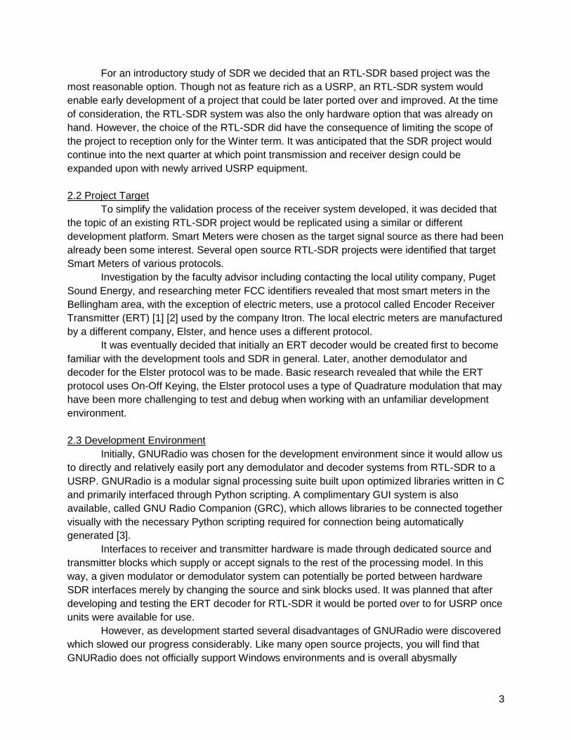
For an introductory study of SDR we decided that an RTL-SDR based project was the
most reasonable option. Though not as feature rich as a USRP, an RTL-SDR system would
enable early development of a project that could be later ported over and improved. At the time
of consideration, the RTL-SDR system was also the only hardware option that was already on
hand. However, the choice of the RTL-SDR did have the consequence of limiting the scope of
the project to reception only for the Winter term. It was anticipated that the SDR project would
continue into the next quarter at which point transmission and receiver design could be
expanded upon with newly arrived USRP equipment.
2.2 Project Target
To simplify the validation process of the receiver system developed, it was decided that
the topic of an existing RTL-SDR project would be replicated using a similar or different
development platform. Smart Meters were chosen as the target signal source as there had been
already been some interest. Several open source RTL-SDR projects were identified that target
Smart Meters of various protocols.
Investigation by the faculty advisor including contacting the local utility company, Puget
Sound Energy, and researching meter FCC identifiers revealed that most smart meters in the
Bellingham area, with the exception of electric meters, use a protocol called Encoder Receiver
Transmitter (ERT) [1] [2] used by the company Itron. The local electric meters are manufactured
by a different company, Elster, and hence uses a different protocol.
It was eventually decided that initially an ERT decoder would be created first to become
familiar with the development tools and SDR in general. Later, another demodulator and
decoder for the Elster protocol was to be made. Basic research revealed that while the ERT
protocol uses On-Off Keying, the Elster protocol uses a type of Quadrature modulation that may
have been more challenging to test and debug when working with an unfamiliar development
environment.
2.3 Development Environment
Initially, GNURadio was chosen for the development environment since it would allow us
to directly and relatively easily port any demodulator and decoder systems from RTL-SDR to a
USRP. GNURadio is a modular signal processing suite built upon optimized libraries written in C
and primarily interfaced through Python scripting. A complimentary GUI system is also
available, called GNU Radio Companion (GRC), which allows libraries to be connected together
visually with the necessary Python scripting required for connection being automatically
generated [3].
Interfaces to receiver and transmitter hardware is made through dedicated source and
transmitter blocks which supply or accept signals to the rest of the processing model. In this
way, a given modulator or demodulator system can potentially be ported between hardware
SDR interfaces merely by changing the source and sink blocks used. It was planned that after
developing and testing the ERT decoder for RTL-SDR it would be ported over to for USRP once
units were available for use.
However, as development started several disadvantages of GNURadio were discovered
which slowed our progress considerably. Like many open source projects, you will find that
GNURadio does not officially support Windows environments and is overall abysmally
4
documented. For this reason we used a Debian based distribution of Linux (Mint 17) inside an
Oracle VMWare virtual machine. This setup then later had to be abandoned when we found that
the drivers necessary to tunnel USB devices from the Windows host to the virtual environment
could not provide the bandwidth necessary for an RTL-SDR dongle without dropped samples
occurring. A separate partition was then created on the development computer for a native
installation of Mint.
From here, progress continued slowly as the true depth of GNURadio’s hundreds of
libraries was discovered. It was clear that while the tools necessary to create an ERT
demodulator and decoder were likely contained within GNURadio, they would not be discovered
particularly quickly by a new user. It was then decided that a better course forward would be to
find a similar RTL-SDR project intended to decode similar OOK modulated signals rather than
building from the ground up.
For this purpose, several open source projects were investigated and examined
revealing yet another flaw of using GNURadio as a rapid development environment. Installing
GNURadio from source along with its dependencies and RTL-SDR blocks is a very lengthy
process which can take up to 4 hours when using an automated script and likely far longer if
installed manually. Unfortunately, the script used [4] installs the latest version of GNURadio,
which at the time of the study was Version 3.7.6. We soon discovered that in the switch from
version 3.6 to 3.7, the locations of GNURadio and associated Python blocks had been
completely reorganized, thus breaking compatibility with all GNURadio projects created with
version 3.6 or earlier. This, unfortunately, included the majority of GNURadio projects written for
RTL-SDR. With the possibility of using existing projects as a map to GNURadio’s functionality
shattered and half the term nearly over, GNURadio was dropped in favor of a better
documented and familiar toolset.
MATLAB was originally passed over in favor of GNURadio due to GNURadio’s better
support for USRP systems. However, the objective of the course was primarily to learn the
foundations of Software Defined Radio for which MATLAB is ultimately the better tool.
Unfortunately, RTL-SDR development in MATLAB requires the use of the Communications
System Toolbox which at the time of study was not part of the university’s license. Therefore a
personal student copy of MATLAB with the toolbox was purchased by the author for
development. This had the side effect of making development operating system agnostic as the
MATLAB environment is largely identical between Windows and Linux.
2.4 Final Project
With the choice of MATLAB and the limited time remaining, it was decided that the
remainder of the course study would consist of implementing a demodulator and decoder for
ERT messages. This system would first operate on pre-recorded meter signals, of known value
after decoding, for validation. Next, the system would be optimized and converted to run in
realtime in conjunction with an RTL-SDR receiver.
As a baseline, we used an open source project called RTLAMR [5] was used to find
neighborhood meter messages. In addition to logging the decoded messages, the raw samples
corresponding to each decoded message were logged to file using the available “-samplefile”
command line argument. To speed development of a binary message decoder/parser, a rough
MATLAB script was created by the course advisor to extract a correct binary string from a

5
manually selected string of samples. After creating the necessary binary decoder, the student
then wrote a revised demodulation script designed for higher efficiency. The design details and
results of this development are covered in the following section.
3. Final Product To begin, we present a more detailed system level diagram of our SDR receiver, this
time considering our desired final system:
Figure 3: Meter Reader System Flow
The challenge is to create a script which can perform all the tasks detailed above fast enough to
keep pace with our RTL-SDR source to the right. We first start with our magnitude conversion:
3.1 Magnitude Conversion
Samples received from the RTL-SDR device, and logged in the RTLAMR signal file, are
in the format of I and Q samples that are each 8bits in size. For OOK modulation, neither the I
nor Q signal bears any important information since we are only interested in the presence or
non-presence of a transmitted carrier signal. Therefore, to partially demodulate the signal we
simply take the magnitude, or absolute value, of the I and Q samples as presented below:
𝑠𝑛 = √(𝐼𝑛 )2 + (𝑄𝑛 )2
In MATLAB, we can accomplish this operation using the “abs()” command for floating point
values. For the native 8bit integers provided by the RTL-SDR device, we can make do with
simply squaring and adding the I and Q samples. To perform a square root function, we would
have to type cast to a floating point, incurring an additional processing overhead that should be
avoided. This stage is important because, as will be shown later, the bit detection algorithm
relies on there being no negative samples.
3.2 Bit Detection
For an oversampled Manchester encoded signal with noise, the message bits can be
extracted using a filter constructed with a convolution function. This is the method used in the
advisor supplied decoder script, but it is useful to understand how it operates so that we can
improve efficiency later. Though the MATLAB implementation uses convolution, the intended
action is actually better understood as a calculation of how closely the signal matches an ideally
6
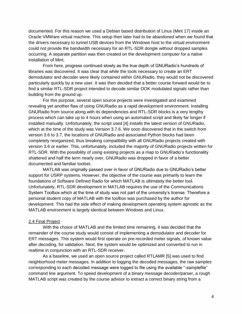
shaped Manchester encoded bit over a given period of time. Below we show the ideally shaped
bit that we would use in our convolution:
Figure 4: Convolution Reference Shape
Convolution essentially takes this ideal shape and slides it over our stream of sample
magnitudes in a buffer, typically the length of a single message. It is useful to note that with the
default RTLAMR sampling rate of 2.392064 MHz and the normal ERT symbol rate of
32.768kbps, each symbol received will be 146 samples long. Each time the waveforms are
shifted over each other, the area enclosed by the two waveforms is calculated and stored in a
new buffer, which incidentally will be 146 terms larger than the input buffer due to the shifting.
As the mask slides across objects that are similarly shaped the calculated result increases in
value until it reaches a peak where the two shapes are most similar to each other. Since the
mask has a negative portion, we will also see a negative counterpart that is called the valley.
Below, the resulting convolution is presented for a sampled signal plotted as processed
from the basic convolution detector provided by the instructor. The original, unfiltered signal has
been multiplied by 30 so that it is visible on the same scale as the convoluted output. The bits
encoded in the original message have been added to the top for better clarity. Also note that the
horizontal grid is in steps of 146 samples.

7
Figure 5: Convolution Detector On Real Signal
A pattern emerges such that for every 146 frames of the convolution, there will be either
a peak or a valley depending upon whether the mask passed over a “one” shape or a “zero”
shape. While noise has some effect on the convolution, it is minimal since the area between the
noise waveform and zero is very small. In order to extract bits from the convoluted output, the
detector merely needs to check the sign of the convolution once every 146 slices. It is not even
necessarily needed to detect when the peaks and valleys occur, but instead simply shift new
samples in as they are received from the receiver, perform the convolution and check for a valid
preamble or other parameter that would confirm the validity of the detected bit stream.
A major disadvantage of using convolution, however, is that it is very mathematically
intensive requiring all elements of the mask and the string of samples are multiplied together at
some point. Ideally, a bit detector would only require adding or subtracting since this is far faster
to execute.
This brings us to the final bit detection method which was developed for the project,
employing cumulative summation rather than convolution. To start we once again present only
single bits. Below are the cumulative summations for a Manchester encoded one and zero:

8
Figure 6: Cumulative Sum of Manchester “1”
Figure 7: Cumulative Sum of Manchester “0”
When visualized in this manner, it is quite apparent that the relative values of the
summation at the start, middle, and end of the symbol frame can be used by the detector. This
can be achieved if the detector compares the values of the summation vector in the following
manner:

9
𝑆𝑜𝑓𝑡𝑏𝑖𝑡(𝑛) = [𝑠𝑢𝑚(𝑠𝑦𝑚𝑏𝑜𝑙(𝑛). 𝑚𝑖𝑑𝑑𝑙𝑒) − 𝑠𝑢𝑚(𝑠𝑦𝑚𝑏𝑜𝑙(𝑛). 𝑠𝑡𝑎𝑟𝑡)]
+ [𝑠𝑢𝑚(𝑠𝑦𝑚𝑏𝑜𝑙(𝑛). 𝑚𝑖𝑑𝑑𝑙𝑒) − 𝑠𝑢𝑚(𝑠𝑦𝑚𝑏𝑜𝑙(𝑛). 𝑒𝑛𝑑)]
= 2 ∗ 𝑠𝑢𝑚(𝑠𝑦𝑚𝑏𝑜𝑙(𝑛). 𝑚𝑖𝑑𝑑𝑙𝑒) − 𝑠𝑢𝑚(𝑠𝑦𝑚𝑏𝑜𝑙(𝑛). 𝑠𝑡𝑎𝑟𝑡) − 𝑠𝑢𝑚(𝑠𝑦𝑚𝑏𝑜𝑙(𝑛). 𝑒𝑛𝑑)
The term “Softbits” is used in this context as a label for an intermediate integer value whose
polarity indicates the value of the detected bit. A related alternative method used in RTLAMR is
to perform the cumulative summation on a larger swath of samples and using a similar equation
to the one above over the entire summation. This produces a kind of sawtooth waveform with
peaks and valleys centered on positive and negative bits. The bits can then be extracted by
using a peak detection algorithm. For simplicity, however, the detector developed again simply
cycles samples through our detection algorithm and parse the bits for identifying information,
such as a preamble, to determine when a valid string of bits has been captured.
At this stage it is worth noting the effect of the carrier frequency used on the
operation of the bit detector. In short, there is actually very little practical effect on the detector
design. The meters make use of frequency hopping across several channels in the 902MHz-
928MHz ISM band. As will be shown below this does not affect the detector, but it does mean
that some number of messages transmitted will not be detected by the system due to the limited
2.2Mhz - 2.7MHz maximum bandwidth of the RTL-SDR receiver.
Since the bit rate of the original intelligence signal (the meter data) does not change
when different transmitting channels are used, the number of samples required to fully capture a
single message will only change with the sampling frequency used. For the best results, a
sampling frequency is used which will yield an equal number of samples for every transmitted
bit. Since development began with logged data from RTLAMR, we use its default sampling
frequency of 2.392064 MHz. Given the intelligence signal data rate of 32.768kbps, there are a
total of 146 samples (combined I and Q) for each transmitted symbol (corresponding to one
Manchester encoded bit).
3.3 Message Validation and Parsing
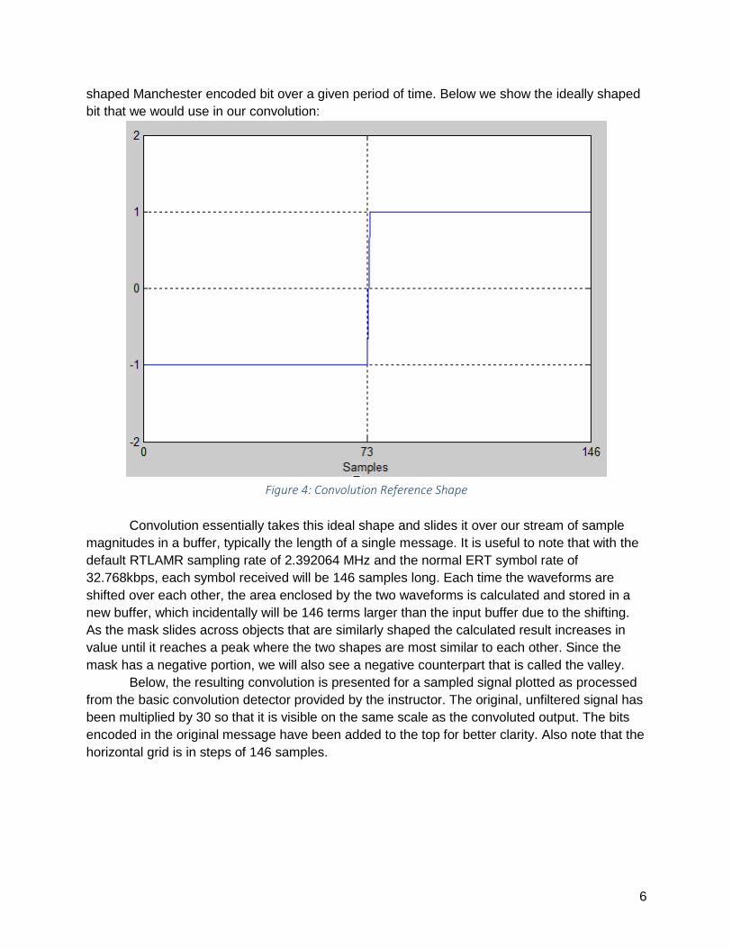
In the Bellingham area, ERT Smart Meters appear to primarily use messages in a format
called Standard Consumption Message (SCM). SCM messages are made up of a total of
12bytes, or 96bits, of data which are transmitted in Manchester encoding and utilizing OOK
modulation as we saw above. The makeup of each message is detailed in the table below [6]:
10
Bits Length Description
1 1 Sync bit. Always 1
2:21 20 Preamble: 0xF2A60
22:23 2 The two most significant bits of the meter ID number
24 1 Reserved bit
25:26 2 Physical tamper flag bits
27:30 4 Meter type (gas, water, etc.)
31:32 2 Encoder tamper flag bits
33:56 24 Commodity consumption value or rate
57:80 24 Remaining meter ID bits
81:96 16 “Checksum” for BCH error detection and correction code
Table 2: Bit Layout of ERT SCM Message
This is the structure of bits we would expect to see if the decoder is operating properly and there
is a minimal amount of noise in the received signal. The most basic check it can perform for
message validity is to compare the first 23 decoded bits to the sync bit plus preamble
(0x1F2A60). If these bits match, then it can move on to the second portion of its validation
procedure which is to perform error checking with the BCH code.
In SCM formatted messages, the checksum is actually the result from passing the rest of
the message, minus the sync bit and preamble, through a BCH polynomial of the following form:
𝑝(𝑥) = 𝑥16 + 𝑥14 + 𝑥13 + 𝑥11 + 𝑥10 + 𝑥9 + 𝑥8 + 𝑥6 + 𝑥5 + 𝑥1 + 𝑥0
BCH codes can be described in terms of “k” and “n” numbers which correspond to the message
length in bits before and after being processed through the polynomial. For the above
polynomial, a “k” value of 239 and an “n” value of 255 are required. It is apparent that in order to
perform the BCH operation, the message must be padded with extra bits. When transmitted, the
59 message bits are padded with 180 zero bits and passed through the BCH polynomial
resulting in 16 extra bits being added onto the end for a total of 255 bits. The 180 zeros are then
truncated and the preamble and sync bit are added.
On the receiving end, the message must once again be padded up to 255bits before running the string of bits through the decoder’s BCH processor, which uses the 16bit “checksum” to detect and correct bit errors. In this case, up to 2 error bits can be detected and

11
corrected. The output of the BCH processor is reduced back to 239bits, of which only about the last 59bits are important. Thankfully, the MATLAB Communications Systems Toolbox includes BCH processing functionality making the implementation of this system rather trivial. By observing the number of bits errors detected and corrected, the decoder can determine if a valid string of bits was decoded. From there it is a trivial process of isolating the relevant strings of bits, converting to data to decimal format, and presenting the message data to the user via the terminal.
4. Optimization and Performance When interfacing an RTL-SDR device through MATLAB, it is necessary to receive samples in batches rather than individually in order to reduce processing overhead. For the detector created, batches of 18688 complex I/Q samples are received, which are subsequently converted to magnitude form and stored in a buffer. The binary detector then parses the first 96*146 samples for bits and passes the result along for validation. If the preamble bits do not match or the BCH code detects any bit errors, then it is assumed that the message was not valid. The decoded bits are discarded and the bit detector begins again after skipping ahead in the buffer by 30 samples. If the preamble does match, and there are no bit errors detected, then it is assumed that a valid message was received and it is subsequently parsed and displayed to the user. To avoid detecting the same message twice, the bit detector jumps ahead a number of samples equal to the message length (96*146 in our case) before operating again. If there is not enough samples in the buffer left to run bit detect again, then execution stops until more samples arrive from the RTL-SDR device. A flowchart of this process is shown below:
Figure 8: Final Meter Reading Flow

12
Unfortunately, it was found that on a typical computer the system was unable to run fast enough to process all samples before new samples were available, resulting in lost samples. While more samples could be skipped to reduce computation, it was found from testing with logged data that more than 30 skipped samples would result in an unacceptable decreases in message detection ability. Worse, it was also noted during testing with log data that even with preamble and bit error checking, erroneous messages were detected and deemed valid. This flies in the face of the expected improbability of erroneously detecting bits aligning in just such a manner that a valid BCH would result. We believe that this may be a problem mostly caused and limited to the concatenated nature of the signal log resulting in valid bits from different messages being unintentionally connected together during decoding.
Conclusion At the time of writing, it may be possible to overcome the overhead of MATLAB by
reducing the sampling frequency from the RTL-SDR device such that an equal number of samples are taken for each message symbol. However, due to serious time constraints this has not been implemented. A potential extension to the project, for future terms, may be to once again attempt a GNURadio version of the system, which may lead to faster performance both running on a PC with an RTL-SDR device or later with a USRP.
However, we can say with confidence that the overarching goal of the course was accomplished. Though the projects undertaken did not yield the desired performance, a great deal was learned about how software based signal processing and logic can be used to process radio signals, in this case nearly in real time. As side effects, a basic understanding of the Linux development environment was gained including working with drivers, Python scripting, and dealing with program dependencies. In short, the course study succeeded in preparing the student for future, more productive work with Software Defined Radios.

13
Bibliography
[1] Q. S. D. Mervin L. Grindahl, "Automatic/remote RF instrument monitoring system". United
States of America Patent US4799059 A, 14 March 1986.
[2] J. R. N. Robert E. Brunius, "Automatic/remote RF instrument reading method and
apparatus". United States of America Patent US4614945 A, 20 February 1985.
[3] J.-P. Lang, "Welcome to GNU Radio!," [Online]. Available:
http://gnuradio.org/redmine/projects/gnuradio/wiki. [Accessed 9 April 2015].
[4] M. Leech, "Shirleys Bay Radio Astronomy Consortium GNURadio Installation Bash Script,"
[Online]. Available: http://www.sbrac.org/files/build-gnuradio. [Accessed 9 April 2015].
[5] D. Hall, "An rtl-sdr receiver for Itron ERT compatible smart meters operating in the 900MHz
ISM band.," [Online]. Available: https://github.com/bemasher/rtlamr. [Accessed 9 April
2015].
[6] D. Hall, "rtlamr: Protocal," [Online]. Available: http://bemasher.github.io/rtlamr/protocol.html.
[Accessed 9 April 2015].

14
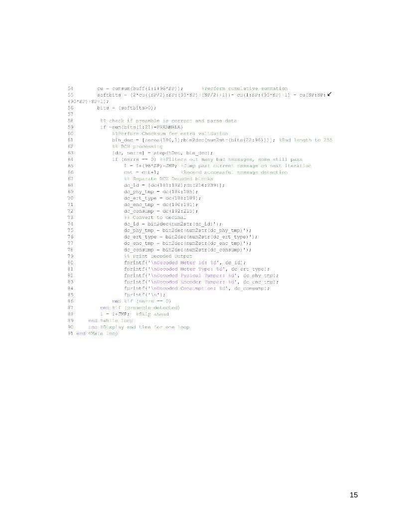
Appendix I: Final MATLAB Project Code
15