etank2000ex
TRANSCRIPT

5/14/2018 ETank2000ex - slidepdf.com
http://slidepdf.com/reader/full/etank2000ex 1/25
Pag
CENL - SINIPEC-01-2012
TANK REPORT: Printed - 2/29/2012 4:53:04 AM
ETANK FULL REPORT - SINIPEC-01-2012
ETank2000 Demo 1.9.15 (20 Jan 2012)
TABLE OF CONTENTS PAGE 1
ETANK SETTINGS SUMMARY PAGE 2
SUMMARY OF DESIGN DATA AND REMARKS PAGE 3
SUMMARY OF RESULTS PAGE 5
ROOF DESIGN PAGE 6
BOTTOM DESIGN PAGE 17
CAPACITIES AND WEIGHTS PAGE 23
MAWP & MAWV SUMMARY PAGE 24

5/14/2018 ETank2000ex - slidepdf.com
http://slidepdf.com/reader/full/etank2000ex 2/25
Pag
CENL - SINIPEC-01-2012
TANK REPORT: Printed - 2/29/2012 4:53:22 AM
ETANK SETTINGS SUMMARY
To Change These ETank Settings, Go To Tools->Options, Behavior Tab.
----------------------------------------------------------------------
No 650 Appendix F Calcs when Tank P = 0 -> Default : False
-> This Tank : FalseShow MAWP / MAWV Calcs : True
Enforce API Minimum thicknesses : True
Enforce API Maximum Roof thickness : True
Enforce Minimum Self Supp. Cone Pitch (2 in 12) : True
Force Non-Annular Btm. to Meet API-650 5.5.1 : FalseSet t.actual to t.required Values : False
Maximum 650 App. S or App. M Multiplier is 1 : True
Enforce API Maximum Nozzle Sizes : True
Max. Self Supported Roof thickness : 0.5 in.
Max. Tank Corr. Allowance : 0.5 in.
External pressure calcs subtract C.A. per V.5 : FalseUse Gauge Material for min thicknesses : False
Enforce API Minimum Live Load : True
Enforce API Minimum Anchor Chair Design Load
= Bolt Yield Load : True

5/14/2018 ETank2000ex - slidepdf.com
http://slidepdf.com/reader/full/etank2000ex 3/25
Pag
CENL - SINIPEC-01-2012
TANK REPORT: Printed - 2/29/2012 4:53:22 AM
SUMMARY OF DESIGN DATA and REMARKS
Job : SINIPEC-01-2012
Date of Calcs. : 2/29/2012 , 04:51 AM
Mfg. or Insp. Date : 3/3/2012
Designer : Ovedje A. UgohProject : Stubb Creek EPF Oil Storage Tank
Tag Number : 02-T-3601A/B
Plant : EPF
Plant Location : Akwa Ibom
Site : Stubb CreekDesign Basis : API-653 4th Edition, April 2009,
& API-650 11th Edition, Addendum 2, Nov 2009
----------------------------------------------------------------------
- TANK NAMEPLATE INFORMATION
----------------------------------------------------------------------
- Operating Ratio: 0.7
- Design Standard:
- API-650 11th Edition, Addendum 2, Nov 2009 -
- (None) -- Roof : A-285 Gr C: 0.3937in. -
- Shell (4): A-283 Gr C: 0.2362in. -
- Shell (3): A-283 Gr C: 0.2362in. -
- Shell (2): A-283 Gr C: 0.2362in. -
- Shell (1): A-283 Gr C: 0.2362in. -
- Bottom : A-36: 0.25in. -
----------------------------------------------------------------------
Design Internal Pressure = 0 PSI or 0 IN. H2O
Design External Pressure = 0 PSI or 0 IN. H2O
MAWP = 2.5000 PSI or 69.28 IN. H2O
MAWV = -0.6575 PSI or -18.22 IN. H2O
OD of Tank = 18 ft
Shell Height = 21.6 ft
S.G. of Contents = 0.7381Max. Liq. Level = 16.4 ft
Re-Rate Temperature = 194 °F
Tank Joint Efficiency = 1
Ground Snow Load = 0 lbf/ft^2
Roof Live Load = 25 lbf/ft^2
Design Roof Dead Load = 0 lbf/ft^2
Basic Wind Velocity = 100 mphWind Importance Factor = 1
Using Seismic Method: NONE
DESIGN NOTES
NOTE 1 : There are tank calculation warnings.Search for * * Warning * * notes.
NOTE 2 : Tank is not subject to API-650 Appendix F.7

5/14/2018 ETank2000ex - slidepdf.com
http://slidepdf.com/reader/full/etank2000ex 4/25
Pag
CENL - SINIPEC-01-2012
TANK REPORT: Printed - 2/29/2012 4:53:22 AM
** NOTE **
A Minimum Liquid Level of 3.28 ft. has been used for this model
as entered on the Shell Design Screen.

5/14/2018 ETank2000ex - slidepdf.com
http://slidepdf.com/reader/full/etank2000ex 5/25
Pag
CENL - SINIPEC-01-2012
TANK REPORT: Printed - 2/29/2012 4:53:22 AM
SUMMARY OF RESULTS
Shell Material Summary (Bottom is 1)
------------------------------------------------------------------------
Shell Width Material Sd St Weight CA
# (ft) (psi) (psi) (lbf) (in)------------------------------------------------------------------------
4 6.9 A-283 Gr C 25,960 27,000 3,756 0.1181
3 4.9 A-283 Gr C 25,960 27,000 2,667 0.1181
2 4.9 A-283 Gr C 23,595 26,000 2,667 0.1181
1 4.9 A-283 Gr C 23,595 26,000 2,667 0.1181------------------------------------------------------------------------
Total Weight 11,757
Shell API 653 Summary (Bottom is 1)
-----------------------------------------------------------------
Shell t.design(Sd) t.test(St) t.external t.required t.actual# (in.) (in.) (in.) (in.) (in.)
-----------------------------------------------------------------
4 0.1192 0.0014 0 0.2181 0.2362
3 0.1269 0.0114 0 0.2181 0.2362
2 0.1362 0.0222 0 0.2181 0.23621 0.1446 0.0326 0 0.2181 0.2362
-----------------------------------------------------------------
Self Supported Domed Roof; Material = A-285 Gr C
t.required = 0.1963 in.
t.actual = 0.3937 in.
Roof Joint Efficiency = 0.85
Weight = 4,469 lbf
Bottom Type: Flat Bottom: Non-Annular
Bottom Floor Material = A-36
t.required = 0.1 in.
t.actual = 0.25 in.
Bottom Joint Efficiency = 1
Total Weight of Bottom = 2,692 lbf
TOP END STIFFENER: L80x80x8, A-36, 372. lbf

5/14/2018 ETank2000ex - slidepdf.com
http://slidepdf.com/reader/full/etank2000ex 6/25
Pag
CENL - SINIPEC-01-2012
TANK REPORT: Printed - 2/29/2012 4:53:23 AM
<Roof Design Per API 653>
DOMED ROOF: A-285 Gr C
OTE: Tank Operating Ratio = 0.7
Roof formulas using 0.4 as operating ratio now use this design value.
JEr = Roof Joint Efficiency = 0.85
Lr = Entered Roof Live Load = 25 lbf/ft^2
Lr_1 = Computed Roof Live Load, including External Pressure
S = Ground Snow Load = 0 lbf/ft^2
Sb = Balanced Design Snow Load = 0 lbf/ft^2
Su = Unbalanced Design Snow Load = 0 lbf/ft^2
Dead_Load = Insulation + Plate_Weight + Added_Dead_Load= (0)(0/12) + 16.0611 + 0
= 16.06 lbf/ft^2
Roof Loads (per API-650 Appendix R)
Pe = PV*144 = 0*144 = 0 lbf/ft^2
e.1b = DL + MAX(Sb,Lr) + 0.7*Pe
= 16.06 + 25 + 0.7*0
= 41.06 lbf/ft^2
e.2b = DL + Pe + 0.4*MAX(Sb,Lr)
= 16.06 + 0 + 0.4*25
= 26.06 lbf/ft^2
T = Balanced Roof Design Load (per API-650 Appendix R)
= MAX(e.1b,e.2b)= 41.06 lbf/ft^2
e.1u = DL + MAX(Su,Lr) + 0.7*Pe
= 16.06 + 25 + 0.7*0
= 41.06 lbf/ft^2
e.2u = DL + Pe + 0.4*MAX(Su,Lr)
= 16.06 + 0 + 0.4*25
= 26.06 lbf/ft^2
U = Unbalanced Roof Design Load (per API-650 Appendix R)= MAX(e.1u,e.2u)
= 41.06 lbf/ft^2
Lr_1 = MAX(T,U) = 41.06 lbf/ft^2
Dish Radius (Rs) = 16.4 ft
Alpha = 56.7166 degrees (angle between the Normal to the roof anda horizontal line at the
roof-to-shell juncture)Theta = 33.2834 degrees (angle between the Normal to the roof and
a vertical line at the
roof-to-shell juncture)

5/14/2018 ETank2000ex - slidepdf.com
http://slidepdf.com/reader/full/etank2000ex 7/25
Pag
CENL - SINIPEC-01-2012
TANK REPORT: Printed - 2/29/2012 4:53:23 AM
Rs = R1 = R2 = 196.8 in.
Rc = ID/2 = 107.7638 in.
<Weight, Surface Area, and Projected Areas of Roof>
Id = OD - 2*t_roof
= 216 - 2*0.3937
= 215.2126 in.
AB = Id /2 - KR
= 215.2126/2 - 0= 107.6063 in.
BC = R - KR
= 196.8 - 0
= 196.8 in.
hR = Height of Roof (Depth of roof)
= R - SQRT[BC^2 - AB^2] + KR= 196.8 - SQRT[196.8^2 - 107.6063^2] + 0
= 2.669 ft
t_ins = Thickness of Roof Insulation
= 0 ft
Ap_Vert = Vertical Projected Area of Roof= PI*([R + t_ins]^2)(Alpha/360) - OD*([R + t_ins] - hR)/2
= PI*(16.4^2)(66.4858/360) - 18*(16.4 - 2.669)/2
= 32.471 ft^2
Horizontal Projected Area of Roof (Per API-650 5.2.1.f)
Xw = Moment Arm of UPLIFT wind force on roof
= 0.5*OD
= 0.5*18
= 9 ftAp = Projected Area of roof for wind moment
= PI*R^2
= PI*9^2
= 254.469 ft^2
Roof_Area = 288*PI*R*hR= 288*PI*16.4*2.669
= 40,064 in^2
Weight = (Density)(t)(Roof_Area)
= (0.2833)(0.3937)(40,064)= 4,469 lbf (New)
= 3,129 lbf (Corroded)
< Uplift on Tank > (per API-650 F.1.2)
OTE: This flat bottom tank is assumed supported by the bottom plate.
If tank not supported by a flat bottom, then uplift calculations
will be N.A., and for reference only.
For flat bottom tank with self supported roof,Net_Uplift = Uplift due to design pressure less
Corroded weight of shell and roof plates.

5/14/2018 ETank2000ex - slidepdf.com
http://slidepdf.com/reader/full/etank2000ex 8/25
Pag
CENL - SINIPEC-01-2012
TANK REPORT: Printed - 2/29/2012 4:53:23 AM
= P * PI / 4 * D ^ 2 * 144 «
- Corr. shell - Corr. roof weight
= 0 * 3.1416 / 4 * 324 * 144 «
- 5,881 - 3,129
= -9,010 lbf
< Uplift Case per API-650 1.1.1 >
P_Uplift = 0 lbf
W_Roof_Plates (corroded) = 3,129 lbfW_Shell (corroded) = 5,881 lbfSince P_Uplift <= W_Roof,
Tank Roof does not need to meet App. F requirements.
<Minimum Thickness of Roof Plate>
ME = 28,799,999/28,799,999 = 1 (per API-650 App. M.5.1)
<Section 5.10.6.1>
t-Calc1 = ME * SQRT[T/45]*R/200 + CA
= 1 * SQRT[41.06/45]*16.4/200 + 0.118
= 0.1963 in.
t-Calc2 = ME * SQRT[U/45]*R/230 + CA= 1 * SQRT[41.06/45]*16.4/230 + 0.118
= 0.1861 in.
t-CalcExt = MAX(t-Calc1,t-Calc2)
= 0.1963 in.
t-Calc = 0.1963 in.
Max_f (due to roof thickness)
= 200(t-CA)/ME/R
= 200(0.2757)/1/16.4
= 3.3622
Max_T1 (due to roof thickness)
= Max_f^2 * 45
= 3.3622^2 * 45
= 508.6975 lbf/ft^2
P_ext_1 (Vacuum limited by roof thickness)
= -[Max_T1 - DL - 0.7 * Max(Snow_Load,Lr)]/144
= -[508.6975 - 16.06 - 0.7 * Max(0,25)]/144
= -1 PSI (per API-650 Section V.1)
P_max_ext = -1 PSI or -27.71 IN. H2O
<Actual Participating Area of Roof-to-Shell Juncture>
(From API-650 Figure F-2)Wc = 0.6 * SQRT[Rc * (t-CA)] (Top Shell Course)
= 0.6 * SQRT[107.7638 * (0.2362 - 0.1181)]
= 2.1405 in.

5/14/2018 ETank2000ex - slidepdf.com
http://slidepdf.com/reader/full/etank2000ex 9/25
Pag
CENL - SINIPEC-01-2012
TANK REPORT: Printed - 2/29/2012 4:53:23 AM
(From API-650 Figure F-2)
Wh = 0.3 * SQRT[R2 * (t-CA)] (or 12", whichever is less)
= 0.3 * SQRT[196.8 * (0.3937 - 0.118)]
= MIN(2.2098, 12)
= 2.2098 in.
Top End Stiffener: L80x80x8
Aa = (Cross-sectional Area of Top End Stiffener)
= 1.906 in^2
Using API-650 Fig. F-2, Detail c End Stiffener Detail
Ashell = Contributing Area due to shell plates
= Wc*(t_shell - CA)
= 2.1405 * (0.2362 - 0.1181)
= 0.253 in^2
Aroof = Contributing Area due to roof plates
= Wh*(t_roof - CA)
= 2.2098 * (0.3937 - 0.118)
= 0.609 in^2
A = Actual Part. Area of Roof-to-Shell Juncture (per API-650)= Aa + Aroof + Ashell
= 1.906 + 0.609 + 0.253
= 2.768 in^2
MINIMUM PARTICIPATING AREA Dome Roof ( Per API-650 Section 5.10.6.2 )p = MAX(U,T)
Fa = Min(Fy_roof,Fy_shell,Fy_stiff)
= Min(30,000,30,000,36,000)
= 30,000 psi
A_min = Minimum Participating Area
= p*D^2/(8*Fa*TAN(Theta))= 41.06*18^2/(8*30,000*TAN(33.2834))
= 0.084 in^2
MaxT_A = Max Roof Load due to Participating Area
( reversing API-650 Section 5.10.6.2 )
= 1500*45*A/(D*R)= 1500*45*2.768/(18*16.4)
= 632.927 lbf/ft^2
P_ext_2 (Due to MaxT_A)= -[Max_T1 - DL - 0.7 * Max(Snow_Load,Lr)]/144
= -[632.927 - 16.06 - 0.7 * Max(0,25)]/144
= -1 PSI (per API-650 Section V.1)
P_max_ext = -1 PSI or -27.71 IN. H2O
t.required = t-Calc = 0.1963 in.
< ROOF DESIGN SUMMARY >
t.required = 0.1963 in.
t.actual = 0.3937 in.

5/14/2018 ETank2000ex - slidepdf.com
http://slidepdf.com/reader/full/etank2000ex 10/25
Page
CENL - SINIPEC-01-2012
TANK REPORT: Printed - 2/29/2012 4:53:23 AM
P_max_internal = 2.5 PSI or 69.28 IN. H2O
P_max_external = -1 PSI or -27.71 IN. H2O

5/14/2018 ETank2000ex - slidepdf.com
http://slidepdf.com/reader/full/etank2000ex 11/25
Page
CENL - SINIPEC-01-2012
TANK REPORT: Printed - 2/29/2012 4:53:23 AM
SHELL COURSE RE-RATING (Bottom Course is #1)
Course # 1; Material: A-283 Gr C; Width = 4.9ft
API-653 ONE FOOT METHOD
Sd = 23,595 PSI (allowable design stress per API-653 4.3.3.1)
RE-RATE CONDITION
G = 0.7381 (per API-653)
< Re-Rate Condition G = 0.7381 >
H' = Effective liquid head at design pressure
= H + 2.31*P(psi)/G
= 16.4 + 2.31*0/0.7381 = 16.4ft
t-Calc = 2.6*OD*(H' - 1)*G/(Sd*E) + CA (per API-653)
= 2.6*18*(16.4 - 1)*0.7381/(23,595*0.85) + 0.1181
= 0.1446 in.
hMax_1 = E*Sd*(t_1 - CA_1)/(2.6*OD*G) + 1
= 0.85*23,595*(0.2362 - 0.1181) / (2.6 * 18 * 0.7381) + 1= 69.569 ft.
Pmax_1 = (hMax_1 - H) * 0.433 * G
= (69.569 - 16.4) * 0.433 * 0.7381
= 16.9927 PSI
Pmax_int_shell = Pmax_1
Pmax_int_shell = 16.9927 PSI
HYDROSTATIC TEST CONDITION
< Re-Rate Condition G = 1 >
H' = Effective liquid head at design pressure
= H + 2.31*P(psi)/G
= 16.4 + 2.31*0/1 = 16.4ft
t.test = 2.6*18*(16.4 - 1)/(26,000*0.85) = 0.0326 in.
Course # 2; Material: A-283 Gr C; Width = 4.9ft
API-653 ONE FOOT METHOD
Sd = 23,595 PSI (allowable design stress per API-653 4.3.3.1)
RE-RATE CONDITION
G = 0.7381 (per API-653)
< Re-Rate Condition G = 0.7381 >
H' = Effective liquid head at design pressure= H + 2.31*P(psi)/G
= 11.5 + 2.31*0/0.7381 = 11.5ft

5/14/2018 ETank2000ex - slidepdf.com
http://slidepdf.com/reader/full/etank2000ex 12/25
Page
CENL - SINIPEC-01-2012
TANK REPORT: Printed - 2/29/2012 4:53:23 AM
t-Calc = 2.6*OD*(H' - 1)*G/(Sd*E) + CA (per API-653)
= 2.6*18*(11.5 - 1)*0.7381/(23,595*0.85) + 0.1181
= 0.1362 in.
hMax_2 = E*Sd*(t_2 - CA_2)/(2.6*OD*G) + 1
= 0.85*23,595*(0.2362 - 0.1181) / (2.6 * 18 * 0.7381) + 1= 69.569 ft.
Pmax_2 = (hMax_2 - H) * 0.433 * G
= (69.569 - 11.5) * 0.433 * 0.7381
= 18.5587 PSI
Pmax_int_shell = Min(Pmax_int_shell, Pmax_2)
= Min(16.9927, 18.5587)
Pmax_int_shell = 16.9927 PSI
HYDROSTATIC TEST CONDITION
< Re-Rate Condition G = 1 >
H' = Effective liquid head at design pressure
= H + 2.31*P(psi)/G= 11.5 + 2.31*0/1 = 11.5ft
t.test = 2.6*18*(11.5 - 1)/(26,000*0.85) = 0.0222 in.
Course # 3; Material: A-283 Gr C; Width = 4.9ft
API-653 ONE FOOT METHOD
Sd = 25,960 PSI (allowable design stress per API-653 4.3.3.1)
RE-RATE CONDITION
G = 0.7381 (per API-653)
< Re-Rate Condition G = 0.7381 >
H' = Effective liquid head at design pressure= H + 2.31*P(psi)/G
= 6.6 + 2.31*0/0.7381 = 6.6ft
t-Calc = 2.6*OD*(H' - 1)*G/(Sd*E) + CA (per API-653)
= 2.6*18*(6.6 - 1)*0.7381/(25,960*0.85) + 0.1181= 0.1269 in.
hMax_3 = E*Sd*(t_3 - CA_3)/(2.6*OD*G) + 1
= 0.85*25,960*(0.2362 - 0.1181) / (2.6 * 18 * 0.7381) + 1
= 76.4419 ft.
Pmax_3 = (hMax_3 - H) * 0.433 * G
= (76.4419 - 6.6) * 0.433 * 0.7381
= 22.3213 PSI
Pmax_int_shell = Min(Pmax_int_shell, Pmax_3)= Min(16.9927, 22.3213)
Pmax_int_shell = 16.9927 PSI

5/14/2018 ETank2000ex - slidepdf.com
http://slidepdf.com/reader/full/etank2000ex 13/25
Page
CENL - SINIPEC-01-2012
TANK REPORT: Printed - 2/29/2012 4:53:23 AM
HYDROSTATIC TEST CONDITION
< Re-Rate Condition G = 1 >
H' = Effective liquid head at design pressure
= H + 2.31*P(psi)/G= 6.6 + 2.31*0/1 = 6.6ft
t.test = 2.6*18*(6.6 - 1)/(27,000*0.85) = 0.0114 in.
Course # 4; Material: A-283 Gr C; Width = 6.9ft
API-653 ONE FOOT METHOD
Sd = 25,960 PSI (allowable design stress per API-653 4.3.3.1)
RE-RATE CONDITION
G = 0.7381 (per API-653)
< Re-Rate Condition G = 0.7381 >
H' = Effective liquid head at design pressure= H + 2.31*P(psi)/G
= 1.7 + 2.31*0/0.7381 = 1.7ft
t-Calc = 2.6*OD*(H' - 1)*G/(Sd*E) + CA (per API-653)
= 2.6*18*(1.7 - 1)*0.7381/(25,960*0.85) + 0.1181= 0.1192 in.
hMax_4 = E*Sd*(t_4 - CA_4)/(2.6*OD*G) + 1
= 0.85*25,960*(0.2362 - 0.1181) / (2.6 * 18 * 0.7381) + 1
= 76.4419 ft.
Pmax_4 = (hMax_4 - H) * 0.433 * G
= (76.4419 - 1.7) * 0.433 * 0.7381
= 23.8873 PSI
Pmax_int_shell = Min(Pmax_int_shell, Pmax_4)
= Min(16.9927, 23.8873)
Pmax_int_shell = 16.9927 PSI
HYDROSTATIC TEST CONDITION
< Re-Rate Condition G = 1 >
H' = Effective liquid head at design pressure
= H + 2.31*P(psi)/G
= 1.7 + 2.31*0/1 = 1.7ft
t.test = 2.6*18*(1.7 - 1)/(27,000*0.85) = 0.0014 in.
Wtr = Transposed Width of each Shell Course= Width*[ t_thinnest / t_course ]^2.5
Transforming Courses (1) to (4)

5/14/2018 ETank2000ex - slidepdf.com
http://slidepdf.com/reader/full/etank2000ex 14/25
Page
CENL - SINIPEC-01-2012
TANK REPORT: Printed - 2/29/2012 4:53:23 AM
Wtr(1) = 4.9*[ 0.2362/0.2362 ]^2.5 = 4.9 ft
Wtr(2) = 4.9*[ 0.2362/0.2362 ]^2.5 = 4.9 ft
Wtr(3) = 4.9*[ 0.2362/0.2362 ]^2.5 = 4.9 ft
Wtr(4) = 6.9*[ 0.2362/0.2362 ]^2.5 = 6.9 ft
Hts (Height of the Transformed Shell)
= SUM{Wtr} = 21.6 ft
INTERMEDIATE WIND GIRDERS (API 650 Section 5.9.7)
V (Wind Speed) = 100 mphVe = vf = Velocity Factor = (vs/120)^2 = (100/120)^2 = 0.6944Re-Rate PV = 0 PSI, OR 0 In. H2O
<TOP END STIFFENER CALCULATIONS>
Z = Required Top Comp Ring Section Modulus (per API-650 5.1.5.9.e)
= 0 in^3
Top Comp. Ring is not required for Self-Supported Roofs
if the requirements of either Section 5.10.5
or 5.10.6 are met.
Actual Z = 0.895 in^3Using L80x80x8, Wc = 3.0311
<INTERMEDIATE STIFFENER CALCULATIONS> (PER API-650 Section 5.9.7)
* * * NOTE: Using the thinnest shell course, t_thinnest,instead of top shell course.
* * * NOTE: Not subtracting corrosion allowance per user setting.
ME = 28,799,999/28,799,999
= 1
Hu = Maximum Height of Unstiffened Shell
= {ME*600,000*t_thinnest*SQRT[t_thinnest/OD]^3} / Ve)
= {1*600,000*0.2362*SQRT[0.2362/18]^3} / 0.6944
= 306.7643 ft
Wtr = Transposed Width of each Shell Course
= Width*[ t_thinnest / t_course ]^2.5
Transforming Courses (1) to (4)
Wtr(1) = 4.9*[ 0.2362/0.2362 ]^2.5 = 4.9 ft
Wtr(2) = 4.9*[ 0.2362/0.2362 ]^2.5 = 4.9 ft
Wtr(3) = 4.9*[ 0.2362/0.2362 ]^2.5 = 4.9 ft
Wtr(4) = 6.9*[ 0.2362/0.2362 ]^2.5 = 6.9 ft
Hts (Height of the Transformed Shell)= SUM{Wtr} = 21.6 ft
L_0 = Hts/# of Stiffeners + 1= 21.6/1 = 21.6 ft.
No Intermediate Wind Girders Needed Since Hu >= L_0

5/14/2018 ETank2000ex - slidepdf.com
http://slidepdf.com/reader/full/etank2000ex 15/25
Page
CENL - SINIPEC-01-2012
TANK REPORT: Printed - 2/29/2012 4:53:23 AM
SHELL COURSE #1 SUMMARY
-------------------------------------------
t-Calc = MAX(t-Calc_650, t_min_ext, t.seismic)
= MAX(0.1446, 0, 0)
= 0.1446 in.
Course Minimum t shall not be less than 0.1" + CA
(per API-653 Section 4.3.3.1)
t-653min = 0.2181 in.
t.required = MAX(t.design, t.min653)
= MAX(0.1446,0.2181) = 0.2181 in.
< API-653 4.3.2.1 >
t1 (lowest average thickness in the shell course)t1 must be >= t.required = 0.2181 in.
t2 (least min. thickness in an area of shell course)
t2 must be >= 0.6*(t.required - CA) + CA = 0.178100 in.
t.actual = 0.2362 in.
Weight = Density*PI*[(12*OD) - t]*12*Width*t= 0.2833*PI*[(12*18)-0.2362]*12*4.9*0.2362
= 2,667 lbf (New)
= 1,334 lbf (Corroded)
SHELL COURSE #2 SUMMARY
-------------------------------------------
t-Calc = MAX(t-Calc_650, t_min_ext, t.seismic)
= MAX(0.1362, 0, 0)
= 0.1362 in.
Course Minimum t shall not be less than 0.1" + CA
(per API-653 Section 4.3.3.1)
t-653min = 0.2181 in.
t.required = MAX(t.design, t.min653)
= MAX(0.1362,0.2181) = 0.2181 in.
< API-653 4.3.2.1 >
t1 (lowest average thickness in the shell course)t1 must be >= t.required = 0.2181 in.
t2 (least min. thickness in an area of shell course)
t2 must be >= 0.6*(t.required - CA) + CA = 0.178100 in.
t.actual = 0.2362 in.
Weight = Density*PI*[(12*OD) - t]*12*Width*t= 0.2833*PI*[(12*18)-0.2362]*12*4.9*0.2362
= 2,667 lbf (New)
= 1,334 lbf (Corroded)
SHELL COURSE #3 SUMMARY
-------------------------------------------

5/14/2018 ETank2000ex - slidepdf.com
http://slidepdf.com/reader/full/etank2000ex 16/25
Page
CENL - SINIPEC-01-2012
TANK REPORT: Printed - 2/29/2012 4:53:23 AM
t-Calc = MAX(t-Calc_650, t_min_ext, t.seismic)
= MAX(0.1269, 0, 0)
= 0.1269 in.
Course Minimum t shall not be less than 0.1" + CA
(per API-653 Section 4.3.3.1)
t-653min = 0.2181 in.
t.required = MAX(t.design, t.min653)
= MAX(0.1269,0.2181) = 0.2181 in.
< API-653 4.3.2.1 >
t1 (lowest average thickness in the shell course)
t1 must be >= t.required = 0.2181 in.
t2 (least min. thickness in an area of shell course)
t2 must be >= 0.6*(t.required - CA) + CA = 0.178100 in.t.actual = 0.2362 in.
Weight = Density*PI*[(12*OD) - t]*12*Width*t
= 0.2833*PI*[(12*18)-0.2362]*12*4.9*0.2362
= 2,667 lbf (New)
= 1,334 lbf (Corroded)
SHELL COURSE #4 SUMMARY
-------------------------------------------
t-Calc = MAX(t-Calc_650, t_min_ext, t.seismic)
= MAX(0.1192, 0, 0)
= 0.1192 in.
Course Minimum t shall not be less than 0.1" + CA
(per API-653 Section 4.3.3.1)
t-653min = 0.2181 in.
t.required = MAX(t.design, t.min653)
= MAX(0.1192,0.2181) = 0.2181 in.
< API-653 4.3.2.1 >
t1 (lowest average thickness in the shell course)
t1 must be >= t.required = 0.2181 in.
t2 (least min. thickness in an area of shell course)
t2 must be >= 0.6*(t.required - CA) + CA = 0.178100 in.t.actual = 0.2362 in.
Weight = Density*PI*[(12*OD) - t]*12*Width*t
= 0.2833*PI*[(12*18)-0.2362]*12*6.9*0.2362
= 3,756 lbf (New)
= 1,879 lbf (Corroded)
5/14/2018 ETank2000ex - slidepdf.com
http://slidepdf.com/reader/full/etank2000ex 17/25
Page
CENL - SINIPEC-01-2012
TANK REPORT: Printed - 2/29/2012 4:53:23 AM
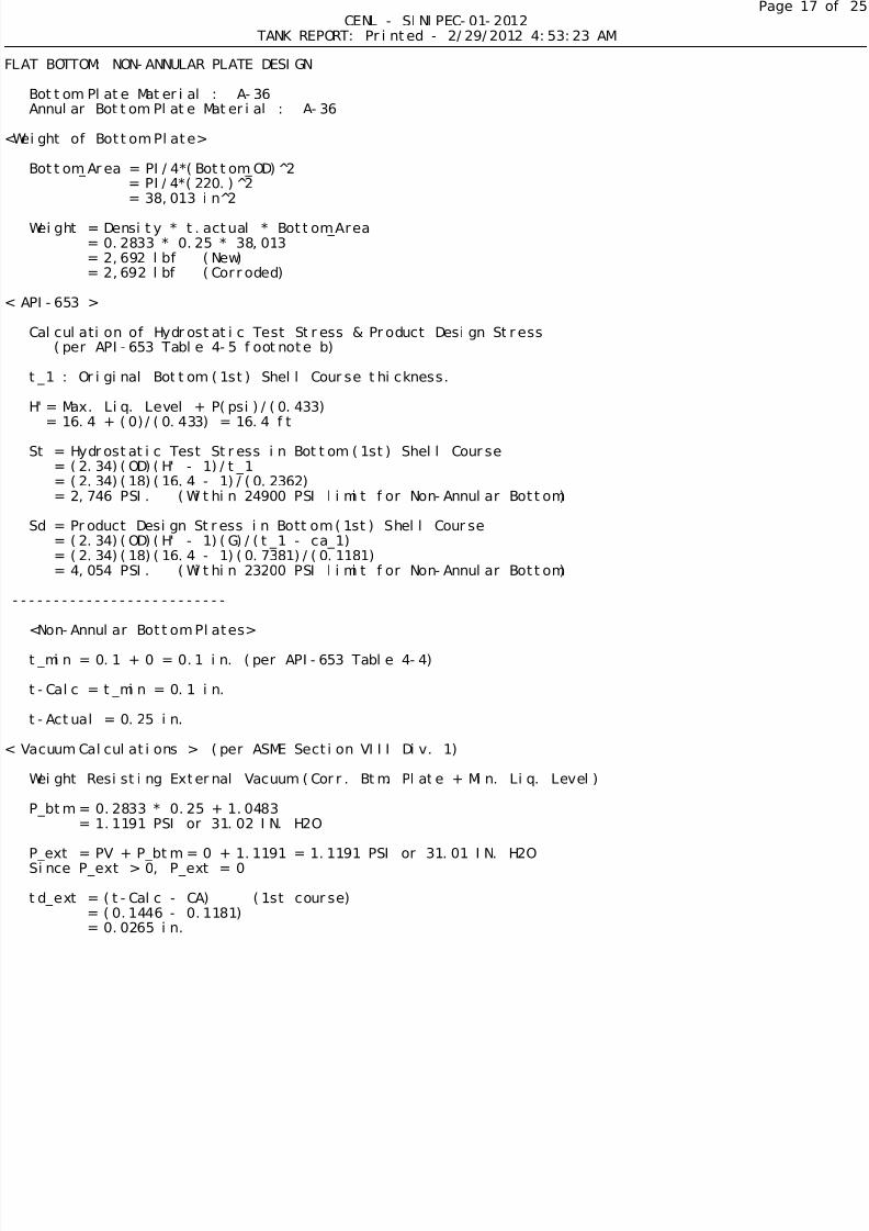
FLAT BOTTOM: NON-ANNULAR PLATE DESIGN
Bottom Plate Material : A-36
Annular Bottom Plate Material : A-36
<Weight of Bottom Plate>
Bottom_Area = PI/4*(Bottom_OD)^2
= PI/4*(220.)^2
= 38,013 in^2
Weight = Density * t.actual * Bottom_Area= 0.2833 * 0.25 * 38,013
= 2,692 lbf (New)
= 2,692 lbf (Corroded)
< API-653 >
Calculation of Hydrostatic Test Stress & Product Design Stress
(per API-653 Table 4-5 footnote b)
t_1 : Original Bottom (1st) Shell Course thickness.
H'= Max. Liq. Level + P(psi)/(0.433)
= 16.4 + (0)/(0.433) = 16.4 ft
St = Hydrostatic Test Stress in Bottom (1st) Shell Course
= (2.34)(OD)(H' - 1)/t_1= (2.34)(18)(16.4 - 1)/(0.2362)
= 2,746 PSI. (Within 24900 PSI limit for Non-Annular Bottom)
Sd = Product Design Stress in Bottom (1st) Shell Course
= (2.34)(OD)(H' - 1)(G)/(t_1 - ca_1)
= (2.34)(18)(16.4 - 1)(0.7381)/(0.1181)= 4,054 PSI. (Within 23200 PSI limit for Non-Annular Bottom)
--------------------------
<Non-Annular Bottom Plates>
t_min = 0.1 + 0 = 0.1 in. (per API-653 Table 4-4)
t-Calc = t_min = 0.1 in.
t-Actual = 0.25 in.
< Vacuum Calculations > (per ASME Section VIII Div. 1)
Weight Resisting External Vacuum (Corr. Btm. Plate + Min. Liq. Level)
P_btm = 0.2833 * 0.25 + 1.0483
= 1.1191 PSI or 31.02 IN. H2O
P_ext = PV + P_btm = 0 + 1.1191 = 1.1191 PSI or 31.01 IN. H2OSince P_ext > 0, P_ext = 0
td_ext = (t-Calc - CA) (1st course)
= (0.1446 - 0.1181)
= 0.0265 in.

5/14/2018 ETank2000ex - slidepdf.com
http://slidepdf.com/reader/full/etank2000ex 18/25
Page
CENL - SINIPEC-01-2012
TANK REPORT: Printed - 2/29/2012 4:53:23 AM
ts = (t.actual - CA) (1st course)
= (0.2362 - 0.1181)
= 0.1181 in.
C = 0.33 * td_ext / ts
= 0.33 * 0.0265 / 0.1181= 0.074
since C < 0.2, set C = 0.2
t-Vac = OD*SQRT(C*P_ext/SE) + CA= (216)*SQRT[(0.2)(0)/(24,882)(1)] + 0= 0 in.
t-Calc = MAX(t-Calc, t-Vac)
= MAX(0.1,0)
= 0.1 in.P_max_external= -1 PSI (per API-650 Section V.1)
-------------------
< FLAT BOTTOM: NON-ANNULAR SUMMARY >
t.required = t-Calc = 0.1 in.
t.actual = 0.25 in.

5/14/2018 ETank2000ex - slidepdf.com
http://slidepdf.com/reader/full/etank2000ex 19/25
Page
CENL - SINIPEC-01-2012
TANK REPORT: Printed - 2/29/2012 4:53:23 AM
ET UPLIFT DUE TO INTERNAL PRESSURE
(See roof report for calculations)
Net_Uplift = -9,010 lbf
Anchorage NOT required for internal pressure.
WIND MOMENT (Per API-650 SECTION 5.11)
OTE: Tank Operating Ratio = 0.7
Wind formulas using 0.4 as operating ratio now use this design value.
vs = Wind Velocity = 100 mphvf = Velocity Factor = (vs/120)^2 = (100/120)^2 = 0.6944
Wind_Uplift = Iw * 30 * vf
= 1 * 30 * 0.6944
= 20.8333 lbf/ft^2
API-650 5.2.1.k Uplift Check
P_F41 = WCtoPSI(0.962*Fy*A*TAN(Theta)/D^2 + 8*t_h)
P_F41 = WCtoPSI(0.962*30,000*2.768*1.3667/18^2 + 8*0.2757)
= 12.2384 PSI
Limit Wind_Uplift/144+P to 1.6*P_F41Wind_Uplift/144 + P = 0.1447 PSI
1.6*P_F41 = 19.5814 PSI
Wind_Uplift/144 + P = MIN(Wind_Uplift/144 + P, 1.6*P_F41)
Wind_Uplift/144 = MIN(Wind_Uplift/144, 1.6*P_F41 - P)Wind_Uplift = MIN(Wind_Uplift, (1.6*P_F41 - P) * 144)
= MIN(20.8333,2,820)
= 20.8333 lbf/ft^2
Id = OD - 2*t_roof
= 216 - 2*0.3937= 215.2126 in.
AB = Id /2 - KR
= 215.2126/2 - 0
= 107.6063 in.
BC = R - KR
= 196.8 - 0= 196.8 in.
hR = Height of Roof (Depth of roof)
= R - SQRT[BC^2 - AB^2] + KR
= 196.8 - SQRT[196.8^2 - 107.6063^2] + 0
= 2.669 ft
t_ins = Thickness of Roof Insulation
= 0 ft
Ap_Vert = Vertical Projected Area of Roof
= PI*([R + t_ins]^2)(Alpha/360) - OD*([R + t_ins] - hR)/2
= PI*(16.4^2)(66.4858/360) - 18*(16.4 - 2.669)/2= 32.471 ft^2
Horizontal Projected Area of Roof (Per API-650 5.2.1.f)

5/14/2018 ETank2000ex - slidepdf.com
http://slidepdf.com/reader/full/etank2000ex 20/25
Page
CENL - SINIPEC-01-2012
TANK REPORT: Printed - 2/29/2012 4:53:23 AM
Xw = Moment Arm of UPLIFT wind force on roof
= 0.5*OD
= 0.5*18
= 9 ft
Ap = Projected Area of roof for wind moment
= PI*R^2= PI*9^2
= 254.469 ft^2
M_roof (Moment Due to Wind Force on Roof)
= (Wind_Uplift)(Ap)(Xw)= (20.8333)(254.469)(9) = 47,713 ft-lbf
Xs (Moment Arm of Wind Force on Shell)
= H/2 = (21.6)/2 = 10.8 ft
As (Projected Area of Shell)= H*(OD + t_ins / 6)
= (21.6)(18 + 0/6) = 388.8 ft^2
M_shell (Moment Due to Wind Force on Shell)
= (Iw)(vf)(18)(As)(Xs)
= (1)(0.6944)(18)(388.8)(10.8) = 52,488 ft-lbf
Mw (Wind moment)
= M_roof + M_shell = 47,713 + 52,488
= 100,201 ft-lbf
W = Net weight (PER API-650 5.11.3)
(Force due to corroded weight of shell and
shell-supported roof plates and weight of
Minimum Liquid less 40% of F.1.2 Uplift force.)
W_net_tank_weight = W_shell + W_roof - 0.7*P*(PI/4)(144)(OD^2)= 5,881 + 3,129 - 0.7*0*(PI/4)(144)(18^2)
= 9,010 lbf
W_min_Liquid = 38,256 lbf
W = W_net_tank_weight + W_min_Liquid= 47,266 lbf
RESISTANCE TO OVERTURNING (per API-650 5.11.2)
An unanchored Tank must meet these two criteria:1) 0.6*Mw + MPi < (MDL + MF_min_liq)/1.5
2) Mw + 0.4MPi < (MDL + MF)/2
Mw = Destabilizing Wind Moment = 100,201 ft-lbf
MPi = Destabilizing Moment about the Shell-to-Bottom Joint from Design «Pressure.
= P*(PI*OD^2/4)*(144)*(OD/2)
= 0*(3.1416*18^2/4)*(144)*(9)= 0 ft-lbf

5/14/2018 ETank2000ex - slidepdf.com
http://slidepdf.com/reader/full/etank2000ex 21/25
Page
CENL - SINIPEC-01-2012
TANK REPORT: Printed - 2/29/2012 4:53:23 AM
MDL = Stabilizing Moment about the Shell-to-Bottom Joint from the Shell and «
Roof weight supported by the Shell.
= (W_shell + W_roof)*OD/2
= (5,881 + 3,129)*9
= 81,090 ft-lbf
tb = Bottom Plate thickness less C.A. = 0.25 in.
wl = Circumferential loading of contents along Shell-To-Bottom Joint.
= 4.67*tb*SQRT(Sy_btm*H_liq)
= 4.67*0.25*SQRT(36,000*16.4)= 897.08 lbf/ft
wl = 0.9 * H_liq * OD (lesser value than above)
= 0.9*16.4*18
= 265.68 lbf/ft
wl_min_liq = Circumferential loading of Minimum-Level contents along «
Shell-To-Bottom Joint.
= 4.67*ta*SQRT(Sy_btm*H_min_liq)
= 4.67*0.25*SQRT(36,000*3.28)
= 401.1853 lbf/ft
MF_min_liq = wa_min_liq*PI*OD
= 401.1853*3.1416*18
= 401.1853 lbf
MF = Stabilizing Moment due to Bottom Plate and Liquid Weight.= (OD/2)*wl*PI*OD
= (9)(265.68)(3.1416)(18)
= 135,215 ft-lbf
Criteria 1
0.6*(100,201) + 0 < (81,090 + 22,686)/1.5Since 60,121 < 69,184, Tank is stable.
Criteria 2
100,201 + 0.4 * 0 < (81,090 + 135,215)/2
Since 100,201 < 108,153, Tank is stable.
RESISTANCE TO SLIDING (per API-650 5.11.4)
F_wind = vF * 18 * As
= 0.6944 * 18 * 388.8
= 4,860 lbf
F_friction = Maximum of 40% of Weight of Tank
= 0.4 * (W_Roof_Corroded + W_Shell_Corroded +
W_Btm_Corroded + W_min_Liquid)
= 0.4 * (3,129 + 5,881 + 2,692 + 38,256)
= 19,983 lbf
No anchorage needed to resist sliding since
F_friction > F_wind

5/14/2018 ETank2000ex - slidepdf.com
http://slidepdf.com/reader/full/etank2000ex 22/25
Page
CENL - SINIPEC-01-2012
TANK REPORT: Printed - 2/29/2012 4:53:23 AM
<Anchorage Requirement>
Anchorage NOT required since Criteria 1, Criteria 2, and Sliding
ARE acceptable.
ANCHOR BOLT CHAIRS NOT SPECIFIED.

5/14/2018 ETank2000ex - slidepdf.com
http://slidepdf.com/reader/full/etank2000ex 23/25
Page
CENL - SINIPEC-01-2012
TANK REPORT: Printed - 2/29/2012 4:53:23 AM
CAPACITIES and WEIGHTS
Maximum Capacity (to upper TL) : 40,938 gal
Design Capacity (to Max Liquid Level) : 31,082 gal
Minimum Capacity (to Min Liquid Level) : 6,216 gal
NetWorking Capacity (Design - Min.) : 24,866 gal
New Condition Corroded
-----------------------------------------------------------
Shell 11,757 lbf 5,881 lbf
Roof Plates 4,469 lbf 3,129 lbfBottom 2,692 lbf 2,692 lbfStiffeners 372 lbf 372 lbf
Nozzle Wgt 0 lbf 0 lbf
Misc Roof Wgt 0 lbf 0 lbf
Misc Shell Wgt 0 lbf 0 lbf
Insulation 0 lbf 0 lbf-----------------------------------------------------------
Total 19,290 lbf 12,074 lbf
Weight of Tank, Empty : 19,290 lbf
Weight of Tank, Full of Product (SG=0.7381): 271,457 lbf
Weight of Tank, Full of Water : 360,934 lbfet Working Weight, Full of Product : 172,458 lbf
et Working Weight, Full of Water : 226,807 lbf
Foundation Area Req'd : 254 ft^2
Foundation Loading, Empty : 75.94 lbf/ft^2
Foundation Loading, Full of Product (SG=0.7381) : 1,069 lbf/ft^2
Foundation Loading, Full of Water : 1,421 lbf/ft^2
SURFACE AREAS
Roof 278 ft^2Shell 1,221 ft^2
Bottom 254 ft^2
Wind Moment 100,201 ft-lbf
Seismic Moment 0 ft-lbf
MISCELLANEOUS ATTACHED ROOF ITEMS
MISCELLANEOUS ATTACHED SHELL ITEMS

5/14/2018 ETank2000ex - slidepdf.com
http://slidepdf.com/reader/full/etank2000ex 24/25
Page
CENL - SINIPEC-01-2012
TANK REPORT: Printed - 2/29/2012 4:53:23 AM
MAWP & MAWV SUMMARY FOR SINIPEC-01-2012
MAXIMUM CALCULATED INTERNAL PRESSURE
MAWP = 2.5 PSI or 69.28 IN. H2O (per API-650 App. F.1.3 & F.7)
MAWP = Maximum Calculated Internal Pressure (due to shell)
= 2.5 PSI or 69.28 IN. H2O
MAWP = Maximum Calculated Internal Pressure (due to roof)
= 2.5 PSI or 69.28 IN. H2O
TANK MAWP** = 2.5 PSI or 69.28 IN. H2O

5/14/2018 ETank2000ex - slidepdf.com
http://slidepdf.com/reader/full/etank2000ex 25/25
Page
CENL - SINIPEC-01-2012
TANK REPORT: Printed - 2/29/2012 4:53:23 AM
* This MAWP calculation assumes a minimum liquid level of 3.28 FT. in the tank.
MAXIMUM CALCULATED EXTERNAL PRESSURE
MAWV = -1 PSI or -27.71 IN. H2O (per API-650 V.1)
MAWV = Maximum Calculated External Pressure (due to shell)
= -0.6575 PSI or -18.22 IN. H2O
MAWV = Maximum Calculated External Pressure (due to roof)= -1 PSI or -27.71 IN. H2O
MAWV = Maximum Calculated External Pressure (due to bottom plate)
= -1 PSI or -27.71 IN. H2O
TANK MAWV = -0.6575 PSI or -18.22 IN. H2O