estimation of mrr using u-shape electrode in...
TRANSCRIPT

ESTIMATION OF MRR USING U-SHAPE
ELECTRODE IN ELECTROCHEMICAL
MACHINING
A THESIS SUBMITTED IN PARTIAL FULFILMENT
OF THE REQUIREMENTS FOR THE DEGREE OF
Master of Technology
In
Mechanical Engineering
BY
UMASANKAR MALLICK
DEPARTMENT OF MECHANICAL ENGINEERING
NATIONAL INSTITUTE OF TECHNOLOGY
ROURKELA

ESTIMATION OF MRR USING U-SHAPE
ELECTRODE IN
ELECTROCHEMICAL MACHINING
A THESIS SUBMITTED IN PARTIAL FULFILMENT
OF THE REQUIREMENTS FOR THE DEGREE OF
Master of Technology
In
Mechanical Engineering
BY
UMASANKAR MALLICK
UNDER THE GUIDENCE OF
Prof. C.K.BISWAS
DEPARTMENT OF MECHANICAL ENGINEERING
NATIONAL INSTITUTE OF TECHNOLOGY
ROURKELA

i
NATIONAL INSTITUTE OF TECHNOLOGY
ROURKELA
CERTIFICATE
This is to certify that thesis entitled, “ESTIMATION OF MRR USING U-SHAPE
ELECTRODE IN ELECTROCHEMICAL MACHINING” submitted by UMASANKAR
MALLICK in partial fulfillment of the requirements for the award of Master of Technology
Degree in Mechanical Engineering with specialization in “Production Engineering” at National
Institute of Technology, Rourkela (Deemed University) is an authentic work carried out by him
under my supervision and guidance. To the best of my knowledge, the matter embodied in this
thesis has not been submitted to any other university/ institute for award of any Degree or
Diploma.
Date: Dr. C.K.BISWAS
Dept. of Mechanical Engineering
National Institute of Technology,
Rourkela-769008

ii
ACKNOWLEDGEMENT It is with a feeling of great pleasure that I would like to express my most sincere heartfelt
gratitude to Prof. C. K. Biswas, Asst. Professor, Dept. of Mechanical Engineering, NIT Rourkela
for suggesting the topic for my thesis report and for his ready and able guidance through out the
course of my preparing the report. I am greatly indebted to him for his constructive suggestions
and criticism from time to time during the course of progress of my work.
I express my sincere thanks to Prof. R.K Sahoo, Head of the Department of Mechanical
Engineering, NIT, Rourkela for providing me the necessary facilities in the department. I am also
thankful to all the staff members of the Department of Mechanical Engineering, Department of
Chemistry, all staff of Machine Shop and to all my well wishers for their inspiration and help. I
express my sincere gratitude to Mr. Biswanath Mukerjee for his timely help during the
experimental work.
I feel pleased and privileged to fulfill my parent ambition and I am greatly indebted to them for
bearing the inconvenience during my M.E. course.
DATE - UMASANKAR MALLICK
ROLLNO-207ME204
iii
ABSTRACT
Non-traditional machining has grown out of the need to machine exotic engineering metallic
materials, composite materials and high tech ceramics having good mechanical properties and
thermal characteristics as well as sufficient electrical conductivity. Electrochemical Machining
developed in late 1950’s has been accepted worldwide as a standard process in manufacturing
and is capable of machining geometrically complex or hard material components, that are precise
and difficult-to-machine such as heat treated tool steels, composites, super alloys, ceramics,
carbides, heat resistant steels etc. being widely used in die and mold making industries,
aerospace, aeronautics and nuclear industries. The principle of anodic dissolution of metal theory
is the most accepted mathematical model for evaluating material removal from electrodes during
electrochemical process. If two suitable metal poles are placed in a conducting electrolyte and a
direct current passed through them, the metal on the positive pole get depleted and its material is
deposited on the negative pole. Keeping this in view, the present work has been undertaken to
finding the material removal rate by electrochemical dissolution of an anodically polarized work
piece with a U-shaped tubular copper electrode. In the experiment, AISI D2 steel is used as
specimen. Experiments were carried out to study the influence of machining parameters such as
feed rate, applied voltage, conductivity and flow rate on the over cuts in length, width and height
of the specified cavity.
iv
CONTENTS Page No.
CERTIFICATE i
ACKNOWLEDGEMENT ii
ABSTRACT iii
CONTENTS iv
LIST OF FIGURES v
LIST OF TABLES vii
CHAPTER-1 INTRODUCTION 1
1.1 Background 1
1.2 Principle of ECM 4
1.3 Successive steps by which an Electrochemical machining proceeds 4
1.4 classification of ECM process 7
1.4.1 Electrochemical Grinding 7
1.4.2 Electrochemical Turning 7
1.4.3 Electrochemical Milling 7
1.4.4 Electrochemical Wire-Cutting 8
1.5 ECM Machine Structure and parameters 9
1.5.1 Servo system 9
1.5.2 Tool feed rate 10
1.5.3 Electrolyte 10
1.5.4 Temperature Control 10
1.5.5 Tool Design 11
1.5.6 Material removal rate 11
v
1.5.7 Surface finish 11
1.6 Characteristics of ECM 12
1.6.1 Advantages of ECM 12
1.6.2 Disadvantages of ECM 13
1.6.3 Applications of ECM 13
CHAPTER-2 LITERATURE SURVEY 16
2.1 Over view on MRR and Effect of parameter on MRR 16
2.2 Over view on tool design 19
2.3 Over view on micro ECM 20
2.4 Objective of present work 23
CHAPTER-3 EXPERIMENTAL WORK 24
3.1 Experimental setup 24
3.2 Making of Brine solution 29
3.3 Specification of work piece material 30
3.4 Methodology of machining 31
3.5 Design of electrode 34
3.6 Taguchi design 38
3.7 Sample calculation 43
3.8 conclusions 46
CHAPTER-4 RESULTS AND DISCUSSIONS 46
4.1 Analysis of experiment and discussion 46
4.2 Effect on slug wt 51

vi
4.3 Effect on over cut (GL) 54
4.4 Effect on over cut (GW) 57
4.5 Effect on over cut (GH) 59
CHAPTER-5 CONCLUSION 63
CHAPTER-6 REFERENCES 64
CHAPTER-7 BIBLIOGRAPHY 69

vii
LIST OF FIFURES:
Figure no Title Page no
1.1 ECM reaction 3
1.2 Schematic representation of ECM 6
1.3 Die sinking 14
1.4 3D profiling 14
1.5 Drilling 15
1.6 Drilling and trepanning 15
3.1 Schematic diagram of ECM 25
3.2 ECM set up 26
3.3 Control panel 27
3.4 Electrolyte chamber 28
3.5 Sample of ECM tool 29
3.6 Step 1 cutting 33
3.7 Step 2 cutting 33
3.8 Step 3 cutting 34
3.9 Design of electrode for step 1 and 3 36
3.10 Design of electrode for step 2 37
3.11 U-shaped electrode for step 2 38
3.12 U-shaped electrode for step 1 and 3 38
3.13 Work piece after machining run 1 and 2 41
3.14 Work piece after machining run 3 and 4 41
3.15 Work piece after machining run 5 and 6 42
3.16 Work piece after machining run 7 and 8 42
4.1 Main effect plot MRR(mean) 47
viii
Figure no Title Page no
4.2 Main effect plot MRR for SN ratios 48
4.3 Scatter plot for MRR 49
4.4 Main effect plot for MRR effective(mean) 50
4.5 Main effect plot for MRR effective for SN ratios 51
4.6 Main effect plot for slug wt (mean) 52
4.7 Main effect plot for slug wt SN ratios 53
4.8 Main effect plot for GL (mean) 55
4.9 Main effect plot for GL SN ratios 56
4.10 Main effect plot for GW (mean) 57
4.11 Main effect plot for GW SN ratios 58
4.12 Main effect plot for GH (mean) 59
4.13 Main effect plot for GH SN ratios 60

ix
LIST OF TABLES:
TABLE NO TITLE PAGE NO
1.1 ECM specification 12
3.1 Description of work piece material 30
3.2 Mechanical and Thermal properties 31
3.3 Material composition 31
3.4 Factor level 39
3.5 L8 orthogonal array 39
3.6 Observation table 40
3.7 Response table 45
4.1 Taguchi analysis table for MRR 48
4.2 Taguchi analysis table for MRR effective 51
4.3 Taguchi analysis table for slug wt 53
4.4 Taguchi analysis table for GL 56
4.5 Taguchi analysis table for GW 58
4.6 Taguchi analysis table for GH 60
4.7 Analysis of variance GL 61
4.8 Analysis of variance GW 61
4.9 Analysis of variance GH 61

1
Chapter 1Chapter 1Chapter 1Chapter 1 INTRODUCTIONINTRODUCTIONINTRODUCTIONINTRODUCTION
1.1BACKGROUND:
Electrochemical Machining (ECM) is a non-traditional machining (NTM) process belonging to
electrochemical category. ECM is opposite of electrochemical or galvanic coating or deposition
process. Thus ECM can be thought of a controlled anodic dissolution at atomic level of the work
piece that is electrically conductive by a shaped tool due to flow of high current at relatively low
potential difference through an electrolyte which is quite often water based neutral salt solution.
The new concept of manufacturing uses non-conventional energy sources like sound, light,
mechanical, chemical, electrical, electrons and ions. With the industrial and technological
growth, development of harder and difficult to machine materials, which find wide application in
aerospace, nuclear engineering and other industries owing to their high strength to weight ratio,
hardness and heat resistance qualities has been witnessed. New developments in the field of
material science have led to new engineering metallic materials, composite materials and high
tech ceramics having good mechanical properties and thermal characteristics as well as sufficient
electrical conductivity so that they can readily be machined by spark erosion. Non-traditional
machining has grown out of the need to machine these exotic materials. The machining
processes are non-traditional in the sense that they do not employ traditional tools for metal
removal and instead they directly use other forms of energy. The problems of high complexity in
shape, size and higher demand for product accuracy and surface finish can be solved through
non-traditional methods. Currently, non-traditional processes possess virtually unlimited
2
capabilities except for volumetric material removal rates, for which great advances have been
made in the past few years to increase the material removal rates. As removal rate increases, the
cost effectiveness of operations also increase, stimulating ever greater uses of non traditional
processes.
Electrochemical Machining (ECM) is the controlled removal of metal by anodic dissolution in an
electrolytic cell in which the work piece is the anode and the tool is cathode. The electrolyte is
pumped through the gap between the tool and the work piece, while direct current is passed
through the cell, to dissolve metal from the work piece. ECM is widely used in machining of
jobs involving intricate shapes and to machine very hard or tough materials those are difficult or
impossible to machine by conventional machining. It is now routinely used for the machining of
aerospace components, critical deburring, Fuel injection system components, ordnance
components etc. ECM is also most suitable for manufacturing various types of dies and moulds.
For the first time ECM is developed for educational institutions, after years of experience and
expertise demonstrating various aspects of electrochemical machining technology. The set up has
robust construction, reliable and sophisticated technology, user friendly operation and is easy for
maintenance. Extra care is taken while designing for operator safety by providing various
protections.
The job to be machined is fixed in the vice, in the machining chamber, that is sealed for any
leakage of electrolyte and is corrosion resistant, having window to see machining operation. Tool
is brought near the job with the help of press buttons provided on the control panel and table
lifting arrangement, maintaining particular gap. The tool progress is observed vertically by servo
motor and is governed by micro controller based programmable drive. Then the process
parameters are set like tool feed rate, voltage, timer, auto/manual mode, etc.
3
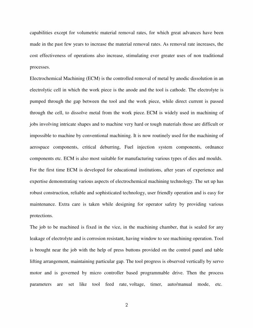
The process is started in the presence of an electrolyte flow that is circulated with the help of
special pump filling the gap between anode (job) and cathode (tool)shown in fig 1.1. Electrolyte
flow is adjusted by flow control valve. The machining is achieved by sinking of tool forming its
replica. During the operation sophisticated control panel takes care of any damage to the
machine by over load and short circuit protections. After desired time interval hooter gives an
indication of completion of the time / process. The small machining area with given power
supply be machined within 30 mins to one hour.
Prior procedures for cathode (tool) design in electrochemical machining have been plagued by
limited applicability, inaccuracy, and no convergence. A least-squares minimization of the
deviation of the simulated anode (work piece) shape from that desired is performed, yielding a
set of parameters in a predefined representation which uniquely define an optimal cathode shape.
Cathode shapes are designed to produce a variety of anode shapes; even anode profiles with
nearly discontinuous slope have been obtained.
Fig1.1 ECM reaction
Material removal rate in electrochemical machining is analyzed in context of over voltage and
conductivity of the electrolyte solution. Electrolyte has three main functions in ECM: It carries
the current between the tool and work piece; it removes the products of the reaction from the
cutting region; and it removes heat produced in operation. Normal electrolyte used for ECM for

4
all common metals & alloys is solution of Sodium Chloride (NaCl) in water. When supply is
switched on, the negative ions Cl migrate towards the anode. They react with the work piece and
form a salt which dissolves in electrolyte. Thus if a job is steel (Fe) and electrolyte is common
salt (NaCl) the following reacting takes place at the anode.
It is observed that over voltage is very sensitive to equilibrium gap and tool feed rate. Material
removal rate decreases due to increase in over voltage and decrease in current efficiency, which
is directly related to the conductivity of the electrolyte solution. It is observed that the corrected
current density is always lower than the actual current. The calculated material removal rate
efficiency is found to be 57%.
1.2 PRINCIPLE OF ECM:
Electrochemical machining is developed on the principle of Faradays and Ohm. In this process,
an electrolyte cell is formed by the anode (work piece) and the cathode (tool) in the midst of a
following electrolyte. The metal is removed by the controlled dissolution of the anode according
to the well known Faradays law of electrolysis. when the electrode are connected to about 20 v
electric supply source, flow of current in the electrolyte is established due to positively charged
ion being attracted towards cathode and vice-versa. Due to electrolysis process at cathode
hydroxyl ion are released which combine with the metal ions of anode to form insoluble metal
hydroxide. Thus the metal is removed in the form of sludge and precipitated in electrolytic cell.
This process continues till the tool has produced its shape in the work piece.
1.3 STEPS BY WHICH ECM PROCEEDS:

5
During ECM, there will be reactions occurring at the electrodes i.e. at the anode or work piece
and at the cathode or the tool along with within the electrolyte. Let us take an example of
machining of low carbon steel which is primarily a ferrous alloy mainly containing iron. For
electrochemical machining of steel, generally a neutral salt solution of sodium chloride (NaCl) is
taken as the electrolyte. The electrolyte and water undergoes ionic dissociation as shown below
as potential difference is applied.
NaCl ↔ Na+
+ Cl-
H2O ↔ H
+
+ (OH)-
As the potential difference is applied between the work piece (anode) and the tool (cathode), the
positive ions move towards the tool and negative ions move towards the work piece. Thus the
hydrogen ions will take away electrons from the cathode (tool) and from hydrogen gas as:
2H+
+ 2e-
= H2↑ at cathode
Similarly, the iron atoms will come out of the anode (work piece) as:
Fe = Fe+ +
+ 2e-
Within the electrolyte iron ions would combine with chloride ions to form iron chloride and
similarly sodium ions would combine with hydroxyl ions to form sodium hydroxide.
Na+
+ OH-
= NaOH
In practice FeCl2
and Fe (OH)2
would form and get precipitated in the form of sludge. In this
manner it can be noted that the work piece gets gradually machined and gets precipitated as the
sludge. Moreover there is not coating on the tool, only hydrogen gas evolves at the tool or
cathode. Fig. 1.2 depicts the electro-chemical reactions schematically. As the material removal

6
takes place due to atomic level dissociation, the machined surface is of excellent surface finish
and stress free.
Fig. 1.2 Schematic representation of electro-chemical reactions
REACTION AT ANODE: REACTION AT CATHOD:
Fe ↔ Fe2+
+ 2e Na+ + e
- ↔ Na
Fe2+
+ 2Cl ↔ FeCl2 Na + H2O ↔ Na (OH) + H+
Fe2+
+ 2OH↔ Fe (OH)2 2H+ + 2e
- ↔ H2↑
FeCl2 + 2 OH↔ Fe(OH)2 + 2 Cl-
2Cl-↔ Cl2 (g) + 2e
-
2FeCl2 + Cl2 ↔2FeCl3
H+ + Cl
- ↔ HCl
2Fe (OH)2 + H2O + O2 ↔2Fe(OH)3↓
Fe(OH)3 + 3HCl ↔FeCl3 + 3H2O
FeCl3 + 3 NaOH ↔ Fe(OH)3↓+ 3NaCl

7
It shows that only hydrogen gas will evolve at cathode and there will be no deposition.
1.4 CLASSIFICATION OF ECM PROCESS
1.4.1 ELECTROCHEMICAL GRINDING PROCESS:
In the electrochemical grinding process metal is removed by electrochemical
decomposition and abrasion of the metal. In this process electrode wheel revolved in the close
proximity to the work piece. Wheel is made of fine diamond particles in metal matrix. The
particle is slightly projecting out from the surface and come in contact with the work surface
with very little pressure. Work piece is connected to the positive terminal and the wheel to the
negative terminal. Thus current flow between the work and wheel. Wheel and its spindle are
insulated from the rest of the machine. During the grinding process, a continuous stream of non
corrosive salt solution is passed through work and tool and it acts both as electrolyte and coolant.
This process is best suited for very precession grinding of hard metal like tungsten carbide tool
tips as the grinding pressure is very less due to which the defect like grinding cracks, tempering
of works, transformation of layer and dimension control difficulties are eliminated. Accuracy of
the order of 0.01mm can be achieved by proper selection of wheel grit size and abrasive
particles.
1.4.2ELECTROCHEMICAL TURNING PROCESS:
In this process the machine has motion of lathe and metal removal tool is a cathode which is
separated from the rotating work surface (anode) by a film of electrolyte. A suitably shaped tool
can produce a desired form on a hard metal in a very short time.
1.4.3 ELECTROCHEMICAL MILLING PROCESS:
This is a form of etching process. In this process job is first cleaned properly. And then some sort
of preventing coating is applied on the particular portion which is not to be machined. The

8
preventive coating is of vinyl plastic. This is applied with the help of a template. Then the job is
exposed to the etching material. Times depend upon the metal to be removed and the strength of
chemical reagent. The metal is removed by the chemical conversion of the metal in to metallic
salt. Material removal rate is mainly dependent on the selected etchant. If the metal is removed at
fast rate with certain etchant then under cutting increases, surface finish decreases and more
heating takes place. The etch rate is therefore limited to 0.02 to 0.04mm per minute. This process
can give complicated shaped pattern on work material. But much depend upon skill of operator.
It is mostly used in aircraft industry. However depth of etching is very less otherwise long time
will be required and at the same time surface finish will decreases. It is mainly used for
embossing, coining, engraving operation. The tooling set up cost is low. Machining is done
without production of burr. And even thin sheet of metal can be processed with ease without
distortion. Material which are brittle in nature can be processed with ease. This process is best
suited for production of printed circuit. Where the basic connection s of the circuit consists of
thin metal strip attached to an insulating phase. These circuits are produced from insulating
board faced with a thin layer of copper. The copper is coated with photosensitive resist and an
imagine of the required circuit is printed photographically on the surface. Etching removed all
the unwanted copper. The etching vapor is very corrosive in nature and therefore, the process
equipment must be kept safe from the etching and other operating equipment.
1.4.4 ELECTROCHEMICAL WIRE CUTTING:
Electrochemical wire cutting process for removal of metal using a wire tool as cathode and work
piece as anode. The work piece can be shaped by relative movement between it and the wire.
The process is similar to wire discharge machining. This process is found to be best suited for
cutting in one or two direction and fine drilling .rectangular wire appears to be better choice over
circular section wire. This process has a limited feed rate compared with conventional ECM. The

9
feed rate is depending on the width of wire and the diameter of work piece. This process is best
suited super finishing with higher surface finish up to 0.15µm. This process is very suitable with
small work piece dimension. Surface finish is better for flat surface than cylindrical. The power
consumption is low and tooling system is cheap. The material removal rate can be controlled
precisely. The surface finish is affected by parameters like feed rate, work piece relation speed
and electrolyte flow rate.
1.5 ECM MACHINE STRUCTUREAND PARAMETERS:
Electrochemical Machining (ECM) is the controlled removal of metal by anodic dissolution in
an electrolytic cell in which the work piece is the anode and the tool is cathode. The electrolyte is
pumped through the gap between the tool and the work piece, while direct current is passed
through the cell, to dissolve metal from the work piece. ECM is widely used in machining of
jobs involving intricate shapes and to machine very hard or tough materials those are difficult or
impossible to machine by conventional machining. It is now routinely used for the machining of
aerospace components, critical deburring, Fuel injection system components, ordnance
components etc. ECM is also most suitable for manufacturing various types of dies and moulds.
For the first time ECM is developed for educational institutions, after years of experience and
expertise demonstrating various aspects of electrochemical machining technology. The set up has
robust construction, reliable and sophisticated technology, user friendly operation and is easy for
maintenance. Extra care is taken while designing for operator safety by providing various
protections.
1.5.1 SERVO SYSTEM:

10
The servo system controls the tool motion relative to the work piece to follow the desired path. It
also controls the gap width within such a range that the discharge process can continue. If tool
electrode moves too fast and touches the work piece, short circuit occurs. Short circuit
contributes little to material removal because the voltage drop between electrodes is small and
the current is limited by the generator. If tool electrode moves too slowly, the gap becomes too
wide and electrical discharge never occurs. Another function of servo system is to retract the tool
electrode when deterioration of gap condition is detected. The width cannot be measured during
machining; other measurable variables are required for servo control.
1.5.2 TOOL FEED RATE
In ECM process gap about 0.01 to 0.07 mm is maintained between tool and work piece. For
smaller gap, the electrical resistance between the tool and work is least and the current is
maximum and accordingly maximum metal is removed. The tool is feed in to the work
depending upon the how fast the metal is to be removed. The movement of the tool slide is
controlled by a hydraulic cylinder giving some range of feed rate.
1.5.3 ELECTROLYTE
The electrolyte is essential for the electrolytic process to work. In addition to removing the heat
generated in the cutting zone to the flow of high current, it also carries the high current and
removes the product of machining. The electrolyte is pumped at about 14kg/cm2 and at speed of
at lest 30 m/s in order to constantly replenish the solution, which must never be allowed to reach
boiling point as it would disturb the current flow. The electrolyte should be of high electrical
conductivity. And be chemically active enough to cause efficient metal removal, and not very
corrosive. The electrolyte must have a good chemical stability.

11
1.5.4 TEMPERATURE CONTROL
Since the conductivity of electrolyte varies with range in temperature, it must be held reasonably
constant; otherwise the equilibrium of the machining gap will change. It may be noted that low
electrolyte temperature result in low metal removal rate and high temperature leads to
vaporization of the electrolyte .It is maintained around (25-60) οC.
1.5.5 TOOL DESIGN
As no tool wear takes place, any good conductor is satisfactory as a tool material, but it must be
designed strong enough to withstand the hydrostatic force, caused by electrolyte being forced at
high speed through the gap between tool and work. The tool is made hollow for drilling holes so
that electrolyte can pass along the bore in tool. Cavitations, stagnation and vortex formation in
electrolyte flow must be avoided because these result a poor surface finish. It should be given
such a shape that the desired shape of job is achieved for the given machining condition.
1.5.6MATERIAL REMOVAL RATE:
It is a function of feed rate which dictates the current passed between the work and the tool. As
the tool advances towards work, gap decreases and current increases which increases more metal
at a rate corresponding to tool advance. A stable spacing between tool and work is thus
established .It may be noted that high feed rate not only is productive but also produces best
quality of surface finish. However feed rate is limited by removal of hydrogen gas and products
of machining. Metal removal rate is lower with low voltage, low electrolyte concentration and
low temperature.
1.5.7 SURFACE FINISH:
ECM can produce surface finish order of 0.4 µm by rotation of tool or work. Any defect on tool
face produce replica on work piece. Tool surface should therefore be polished. The finish is

12
better in harder material. For optimum surface finish, careful electrode design, maximum feed
rate, and surface improving additives in electrolyte are selected. Low voltage decreases the
equilibrium machining gap and result in better surface finish and tolerance control. Low
electrolyte concentration decreases the machining gap and gives the better surface finish. Low
electrolytic temperature also promotes better surface finish.
1.6 CHARACTERSTICS OF ELECTROCHEMICAL MACHINING
PROCESS:
Material removal mechanism controlled removal of metal by anodic dissolution in an electrolytic
medium. It consists of advantage of ECM, Disadvantage of ECM and application of ECM.
Table-1.1 ECM specification
Tool Copper, brass or steel
Power supply Constant voltage 5-30 DC volt
Current 50-40,000 amp
Material removal rate 1600 mm3/min
Specific power consumption 7w/mm3/min
Electrolytic solution Neutral salt, brine solution,
Accuracy and surface finish 0.02 mm, 0.4µm
Application Machining hard material
Limitation High specific energy consumption
Mechanical properties Stress free machining, reduce tool wear
Surface properties No thermal damage
1.6.1 ADVANTAGE OF ECM:

13
Electrochemical machining is a promising alternative if conventional mechanical manufacturing
processes reach technical as well as economical limitations. Nowadays, ECM is established for
burr removing, shape manufacturing and drilling of jet engine parts. Considering these
advantages ECM is a suitable technique for machining mechanical hard to cut materials such as
carbide metals or cermets.
[1] No mechanical stress impact into the processed work piece.
[2] No thermal impact of the work piece.
[3] The removal rate is not determined by the hardness and toughness of the material.
[4] No process related tool wear.
[5] Great versatility for machining of geometrical complex shapes.
[6] No burr formation.
1.6.2DISADVANTEGE OF ECM:
[1] High specific energy consumption.
[2] Not suited for non-conducting pieces.
[3] High initial and working cost.
1.6.3 APPLICATION OF ECM:
ECM technique removes material by atomic level dissolution of the same by electrochemical
action. Thus the material removal rate or machining is not dependent on the mechanical or
physical properties of the work material. It only depends on the atomic weight and valency of the
work material and the condition that it should be electrically conductive. Thus ECM can machine
any electrically conductive work material irrespective of their hardness, strength or even thermal

14
properties. Moreover as ECM leads to atomic level dissolution, the surface finish is excellent
with almost stress free machined surface and without any thermal damage.
ECM is used for:
• Die sinking (Fig 1.3)
• Profiling and contouring (Fig 1.4)
• Trepanning (Fig 1.6)
• Grinding
• Drilling (Fig 1.5)
• Micro-machining
Fig 1.3 DIE SINKING

15
Fig1.4 3D profiling
Fig1.5 Drilling

16
Fig1.6 Drilling and Trepanning

17
CHAPTER 2CHAPTER 2CHAPTER 2CHAPTER 2 LITERATURE REVIEW:LITERATURE REVIEW:LITERATURE REVIEW:LITERATURE REVIEW:
After going through all the selected paper related to MRR, we are broadly classified all the paper
in to three different category, i.e. paper related to material removal rate and effect of parameters
on MRR, some paper related to tool design and rest of the paper related to micro ECM.
2.1 Overview on MRR and effect of parameters on MRR:
B. Bhattacharyya et.al [1] has reported that the electrochemical micro-machining (EMM)
appears to be promising as a future micro-machining technique since in many areas of
applications, it offers several advantages. A suitable micro-tool vibration system has been
developed, which consists of tool-holding unit, micro-tool vibrating unit, etc. The developed
system was used successfully to control material removal rate (MRR) and machining accuracy to
meet the micro-machining requirements. Micro-holes have been produced on thin copper work
piece by EMM with stainless-steel micro-tool. Experiments have been carried out to investigate
the most effective values of process parameters such as micro-tool vibration frequency,
amplitude and electrolyte concentration for producing micro-hole with high accuracy and
appreciable amount of MRR.
Jo ao Cirilo da Silva Neto et.al [2] shows a study of the intervening variables in
electrochemical machining (ECM). The material removal rate (MRR), roughness and over-cut
were studied in this paper. Four parameters were changed during the experiments: feed rate,
electrolyte, flow rate of the electrolyte and voltage. Two electrolytic solutions were used: sodium
18
chloride (NaCl) and sodium nitrate (NaNO3). The results show that feed rate was the main
parameter affecting the material removal rate.
S K Mukherjee et.al [3] discusses about role of electrolyte [NaCl] in current-carrying processes
in electrochemical machining of iron work piece has been analyses in light of Onsager equation
of strong electrolyte. Over-voltage-calculated with respect to equilibrium gap and penetration
rate, shows that only a narrow range of equilibrium gap and penetration rate are admissible.
K. P. Rajurkar et.al [4] discussed about the main advantages of the electrochemical machining
(ECM) process, such as high material removal rates and smooth, damage-free machined surface,
are often offset by the poor dimensional control . This paper presents an ECM control model
based on the basic ECM dynamics that accounts for the dynamic nature of the ECM process. The
state space methodology is applied to transform it into the control model applicable to an ECM
control system based on a digital computer. The simulations have been made for the model
verification and controller design.
S.K. Mukherjee et.al [5] defined that Material removal rate (MRR) of aluminum work piece has
been obtained by electrochemical machining using NaCl electrolyte at different current densities
and compared with the theoretical values. It is also concluded that resistance of the electrolyte
solution decrease sharply with increasing current densities, and simultaneously the over-voltage
of the system initially increases and then attains a saturation value with increasing current
densities.
V.K. Jain et.al [6] has reported that electrochemical spark machining (ECSM) process has been
successfully applied for cutting of quartz using a controlled feed and a wedge edged tool. Only
cathode works as a tool, i.e. ECSM with reverse polarity (ECSMWRP) as well as ECSM with
direct polarity (ECSWDP) have been used to machine quartz plates. In ECSMWRP, deep crater
19
on the anode (as a tool) and work piece interface is formed because of chemical reaction. The
cutting is possible even if we make auxiliary electrode of small size.
K.L. Bhondwe et.al [7] in this paper attempts to develop a thermal model for the calculation of
material removal rate (MRR) during ECSM. First, temperature distribution within zone of
influence of single spark is obtained with the application of finite element method (FEM). The
nodal temperature plays an important role estimating MRR. The developed FEM based thermal
model is found to be in the range of accuracy with the experimental results. The increase in MRR
is found to increase with increase in electrolyte concentration.
S. Kumara et.al [8] discussed about the Material removal rate (MRR) of aluminum work piece
has been obtained by electrochemical machining using NaCl electrolyte at different current
densities. Also resistance of the electrolyte solution decrease sharply with increasing current
densities. The over-voltage of the system initially increases and then attains a saturation value
with increasing current densities.
V.K. Jain et.al [9] has shown that the electrochemical spark machining (ECSM) process has
been useful for machining of low machine ability high-strength electrically non-conducting
materials. In the present work, the electrochemical discharge is modeled as a phenomenon
similar to that which occurs in arc discharge valves. The spark energy and the approximate order
of hydrogen gas bubble diameter are computed by the proposed valve theory. Material removal
rate is evaluated by modeling the problem as a 3-D unsteady state heat conduction problem.
R V Rao et.al [10] discussed about the values of important process parameters of
electrochemical machining processes such as the tool feed rate, electrolyte flow velocity, and
applied voltage play a significant role in optimizing the measures of process performance. These
include dimensional accuracy, tool life, material removal rate, and machining cost. In this paper,
20
a particle optimization algorithm is presented to find the optimal combination of process
parameters for an electrochemical machining process. The objectives considered are dimensional
accuracy, tool life, and the material removal rate.
B. Bhattacharyya et.al [11] has highlighted that features of the development of mathematical
model for correlating the interactive and higher-order influences of various machining
parameters. I.e. the metal removal rate and the overcut phenomena, through response surface
methodology (RSM), utilizing relevant experimental data as obtained through experimentation.
This paper also highlights mathematical models for analyzing the effects of various process
parameters on the machining rate and overcut phenomena. These parameters can be used in order
to achieve maximization of the metal removal rate and the minimum overcut effects for optimal
accuracy of shape features.
2.2 Overview on tool design:
Yuming Zhou et.al [12] discussed about the Prior procedures for cathode (tool) design in
electrochemical machining. In this paper actually develop and test a new approach to this
problem which overcomes these difficulties by employing a finite element method within an
optimization formulation. A least-squares minimization of the deviation of the simulated anode
(work piece) shape from that desired is performed, yielding a set of parameters in a predefined
representation which uniquely define an optimal cathode shape.
Jerzy Kozak et.al [13] discussed about the theoretical and experimental investigations of the
relationship between the characteristic shape dimensions imported upon the anode-work piece
surface by the micro-features of the cathode-tool electrode under given machining conditions are
presented. This research included the study of electrochemical copying of slots, mini-holes,
grooves and insulating groove features. The limiting conditions of micro-ECM are considered

21
from the point of view of copying and micro-shaping using non-profiled tool electrodes. For
improving micro-machining capabilities of ECM processes, the application of ultra-short pulse
current and ultra-small gap size is recommended.
K.P. Rajurkar et.al [14] had shown that ECM process now increasingly being applied in other
industries where parts with difficult-to-cut materials and complex geometry are required. In this
paper the latest advances are discussed, and the principal issues in ECM development and related
research are raised. Developments in tool design, pulse current, micro-shaping, finishing,
numerically controlled, environmental concerns, hybrid processes, and recent industrial
applications, are covered.
J.A. Westley et.al [15] discussed about the study electrolyte flow. This paper tries to identify the
factors, such as insulation requirements and machined face considerations that could relate to
other ECM components. These observations would then be made use of when producing
subsequent ECM electrodes. In this paper work has been carried out by adapting new electrodes
for a casting gate removal process.
Chunhua Sun et.al [16] highlighted about the accurate prediction of tool shape for
electrochemical machining (ECM). This paper proposes an approach using finite element method
(FEM) to design tool in ECM. This method is capable of designing three-dimensional freeform
surface tool from the scanned data of known work piece. It possesses high computing efficiency,
good accuracy and flexible boundary treatment without the need for iterative procedure.
2.3 Overview on Micro ECM:
H. Hocheng et.al [17] reported about the process to erode a hole of hundreds of micrometers on
the metal surface. The paper also discusses the influence of experimental variables including
time of electrolysis, voltage, molar concentration of electrolyte and electrode gap upon the

22
amount of material removal and diameter of machined hole. The results of experiment show the
material removal increases with increasing electrical voltage, molar concentration of electrolyte.
Anjali V. Kulkarni et.al [18] discussed about the current trends and techniques used for micro
fabrication of parts. This paper tries to establish a viable, cost effective and fast micro fabrication
process. Focus is on the use of Electrochemical spark (ECS) for layered manufacturing in
micron.
S. K. Mukherjee et.al [19] reported about the Material removal rate in electrochemical
machining by using over voltage and conductivity of the electrolyte solution. It is observed that
over voltage plays an important role equilibrium gap and tool feed rate. Material removal rate
decreases due to increase in over voltage and decrease in current efficiency, which is directly
related to the conductivity of the electrolyte solution.
A. K. M. De Silva et.al [20] discussed about the Electrochemical machining (ECM), which is
used to achieve accuracy better than 5 µm and surface finish 0.03ms µRa by using pulsed power
of relatively short durations (1 - 10 µs) and narrow inter-electrode gaps (10 – 50 µm). The
narrow gaps make the process much more complex than normal ECM. An empirical model is
developed to predict and optimize the process parameters such as dissolution efficiency, current
density, electrolyte concentration and pulse duration, in narrow gaps.
K.L. Bhondwe et.al [21] written about the Electro-chemical spark machining (ECSM) and
electro discharge machining (EDM). It shows like ECM and EDM, ECSM is capable of
machining electrically non-conducting materials. This paper attempts to develop a thermal model
for the calculation of material removal rate (MRR) by using ECS. The developed FEM based
thermal model is found to be suitable for this experimental result. The increase in MRR is found

23
to increase with increase in electrolyte concentration due to ECSM of soda lime glass work piece
material.
Mohan Sen et.al [22] discussed about the Electrochemical machining processes provide for
drilling macro- and micro-holes with exceptionally smooth surface and reasonably acceptable
taper in numerous industrial applications particularly in aerospace, electronic, computer and
micro-mechanics industries. Also this paper highlights about the hole-drilling processes like jet-
electrochemical drilling have found acceptance in producing large number of quality holes in
difficult-to-machine materials. This paper highlights the recent developments, new trends and the
effect of key factors influencing the quality of the holes produced by these processes.
B. H. Kim et.al [23] discussed about the Micro electrochemical machining (ECM) using ultra
short pulses. 0.1 M sulfuric acid was used as electrolyte and 3D micro structures were machined
on stainless steel. In this paper it shows how to prevent taper, by using a disk-type electrode. To
improve productivity, multiple electrodes were applied and multiple structures were machined
simultaneously. Since the wear of tool electrode is negligible in ECM
Jerzy Kozak et.al [24] has reported that this research included the study of electrochemical
copying of slots, mini-holes, grooves and insulating groove features. The limiting conditions of
micro-ECM are considered from the point of view of copying and micro-shaping using non-
profiled tool electrodes. For improving micro-machining capabilities of ECM processes, the
application of ultra-short pulse current and ultra-small gap size is recommended which is the
main point of discussion in this paper.
M.S. Hewidy et.al [25] discussed about the practical application of electrochemical machining.
By using low frequency vibration to the tool electrode in electrochemical machining we can
improve accuracy and quality of the machined surface. This paper presents an analytical

24
approach to establish mathematical model to asses the mechanism of metal removal for this
novel and hybrid technique. The effect of input parameters and machining conditions on the
effectiveness of tool vibration during ECM has been taken in to account.
M. Kock et.al [26] has reported about the application of ultra short voltage pulses
electrochemical reactions which can be used for nanometer accuracy, and allows for high
precision machining of electrochemical active materials. Depending on the average potentials of
tool and work piece, overall corrosion of the work piece and the location of the counter reaction
of work piece dissolution can be controlled.
Se Hyun Ahna et.al [27] discussed about the rare application of Electro-chemical machining in
micro machining because the electric field is not localized. In this work, ultra short pulses with
tens of nanosecond duration are used to localize dissolution area. The effects of voltage, pulse
duration, and pulse frequency on the localization distance were studied. High quality micro hole
with 8 µm diameter was drilled on 304 stainless steel foil with 20 µm thickness used as work
piece.
2.4 OBJECTIVE OF PRESENT WORK:
The objective of present work is an attempt to finding out the feasibility of making blind cavity
using U-shaped tubular copper electrode in electrochemical machining. The work piece material
is AISI D2 steel and the machining parameters selected for study are feed rate, diameter of
electrode, flow rate and electrolyte conductivity, with Taguchi design approach. In my work,
the voltage across the work piece-tool is kept constant.

25
CHAPTER 3 CHAPTER 3 CHAPTER 3 CHAPTER 3 EXPERIMENTAL WORKEXPERIMENTAL WORKEXPERIMENTAL WORKEXPERIMENTAL WORK
INTRODUCTION:
In this chapter we are going to discuss about the experimental work which is consisting about
experimental set up, selection of work piece of material, design of electrode, making of
electrolytic solution and formation of factor level using Taguchi design. By taking all this
information in account we will calculate the material removal rate.
3.1 EXPERIMENTAL SET UP:
For this experiment the whole work has been carried out by Electrochemical Machining set up
from Metatech-Industry, Pune which is having Supply of - 415 v +/- 10%, 3 phase AC, 50 HZ.
And consist of three major sub systems which are being discussed in this chapter.
The set up consists of three major sub systems.
1. Machining Cell
2. Control Panel
3. Electrolyte Circulation
Machining Cell
This electro-mechanical assembly is a sturdy structure, associated with precision
machined components, servo motorized vertical up / down movement of tool, an electrolyte
dispensing arrangement, illuminated machining chamber with see through window, job fixing
vice, job table lifting mechanism and sturdy stand. All the exposed components, parts have
undergone proper material selection and coating / plating for corrosion protection.

26
Technical Data
• Tool area - 30 mm2.
• Cross head stroke - 150 mm.
• Job holder - 100 mm opening X 50 mm depth X 100 mm width.
• Tool feed motor - DC Servo type.
Fig 3.1 Schamatic diagram of ECM

27
Fig 3.2 ECM set up
Control Panel
The power supply is a perfect integration of, high current electrical, power electronics and
precision programmable microcontroller based technologies. Since the machine operates at very
low voltage, there are no chances of any electrical shocks during operation. Which shown in fig
3.3.

28
Technical Data:
• Electrical Out Put Rating - 0-300 Amps. DC at any voltage from 0 - 20 V.
• Efficiency - Better than 80% at partial & full load condition.
• Power Factor - Better than 85.
• Protections - Over load, Short circuit, single phasing.
• Operation Modes - Manual / Automatic.
• Timer - 0 - 99.9 min.
• Tool Feed - 0.2 to 2 mm / min.
• Z Axis Control - Forward, reverse, auto forward / reverse, through micro controller.
• Supply - 415 v +/- 10%, 3 phase AC, 50 HZ
Fig 3.3 control panel

29
Electrolyte Circulation system:
The electrolyte is pumped from a tank, lined by corrosion resistant coating with the help of
corrosion resistant pump & is fed to the job. Spent electrolyte will return to the tank. The
hydroxide sludge arising will settle at the bottom of the tank & can be easily drained out.
Electrolyte supply shall be governed by flow control valve. Extra electrolyte flow is by-
passed to the tank. Reservoir provides separate settling and siphoning compartments. All fittings
are of corrosion resistant material or of S.S., as necessary.
Fig 3.4 electrolyte chamber
30
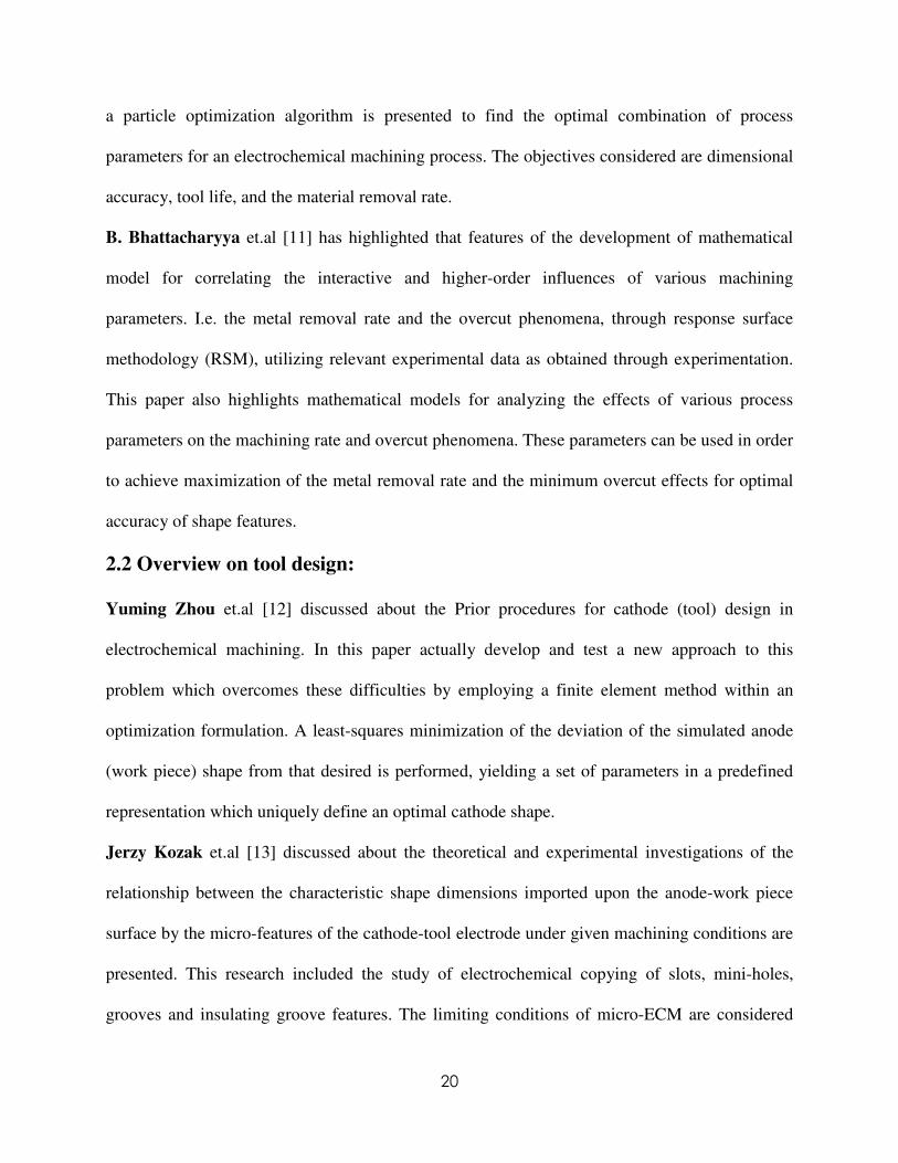
Fig 3.5 Sample ECM tools
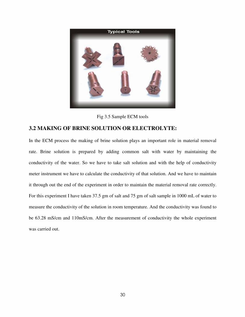
3.2 MAKING OF BRINE SOLUTION OR ELECTROLYTE:
In the ECM process the making of brine solution plays an important role in material removal
rate. Brine solution is prepared by adding common salt with water by maintaining the
conductivity of the water. So we have to take salt solution and with the help of conductivity
meter instrument we have to calculate the conductivity of that solution. And we have to maintain
it through out the end of the experiment in order to maintain the material removal rate correctly.
For this experiment I have taken 37.5 gm of salt and 75 gm of salt sample in 1000 mL of water to
measure the conductivity of the solution in room temperature. And the conductivity was found to
be 63.28 mS/cm and 110mS/cm. After the measurement of conductivity the whole experiment
was carried out.

31
3.3 SPECFICATION OF WORKPIECE MATERIAL:
Work piece material: AISI D2 Tool Steel
Electrochemical machining (ECM) employs anodic dissolution to shape metals and was
developed as a method for machining high-strength, heat-resistant alloys which were extremely
difficult to cut by any other established methods. The ECM process connects the work piece
(anode) to the tool (cathode) via an electrolytic cell, through which an electrolyte is pumped
when a potential difference is applied, current flows as the result of electrochemical reactions
taking place at the surfaces of both electrodes. The reaction at the anode surface removes
material by the oxidation of metal atoms, while the cathode surface is unaffected by the
hydrogen reduction reaction typically occurring there.
For my experiment we have chosen AISI D2 steel as work piece. Work piece is having
dimension of 100 mm in diameter and 60 mm in thickness. I have taken 4 pieces of AISI D2
material and carried out the experiment .In each work piece two cavities are done keeping the
length of 35mm, width of 45mm, and height of 25mm in dimension. And the corresponding
material removal rate is calculated by taking initial and final weight of work piece before and
after the experiment.
Table 3.1 Description of work piece material
Category Steel
Class Tool steel
Type High-carbon, high-chromium cold work steel
Designations Germany: DIN 1.2379
Italy: UNI KU
United Kingdom: B.S. BD 2
United States: ASTM A681 , FED QQ-T-570 , SAE J437 , SAE J438 ,
UNS T30402

32
Table 3.2 Mechanical and Thermal Properties
Parameter value
Density (×1000 kg/m3) at 25 ° C 7.7
Poisson's Ratio 0.27-0.30
Elastic Modulus (GPa) 190-210
Thermal Expansion (10-6
/ºC) at 20-100 ° C 10.4
Table3.3 Material composition
Element Weight %
C 1.40-1.60
Mn 0.60
Si 0.60
Cr 11.00-13.00
Ni 0.30
Mo 0.70-1.20
V 1.10
Co 1.00
Cu 0.25
P 0.03
S 0.03
3.4 METHODOLOGY OF MACHINING:
STEP 1:
After setting all the parameters in the control panel and setting work piece in the chamber cutting
was started by using U-shaped electrode. In this step work piece kept in horizontal position, and
by using a vertical U-shaped electrode cutting started from the centre position. We should be
very much careful such that tip of the electrode should not touch the surface of the electrode. The
33
U-shaped electrode should penetrate up to the length of 25mm in the work piece. Then we have
to stop the process, and we have to go for step 2. Fig. 3.6 describes the step 1.
STEP 2:
Again all the defined parameters are to be set in the control panel. Now the position of the work
piece is being changed from horizontal to vertical position. In the same manner electrode also
changed. In this step electrode cut the work piece in vertical manner, i.e. electrode comes from
top position to bottom of the work piece. Here electrodes have to cut a length of 35 mm distance
in the work piece. During the whole process the time of cutting of the work piece at certain feed
rate is being noted down. And we have to go for step 3. Illustration of step 2 is given in Fig.3.7.
STEP-3:
Again after finishing step 2 all the parameters of the corresponding experiment again set in the
control panel. We have to place in the work piece again in horizontal position to cut left portion
of the work piece. Again vertical electrode is being used the work piece from the end position.
Here the penetration of the electrode is less than the 1st step and the corresponding time
requirement also less than step 1. After the electrode penetrates about 25mm the cavity is being
made in the work piece. A small piece is left after cutting is over .We had to measure the weight
of the left piece. Then the final weight of the work piece is being measured. And MRR is
calculated. The machining step 3 is given in Fig 3.8.

34
Figure 3.6 Step 1
Figure 3.7 Step 2

35
Figure3.8 Step 3
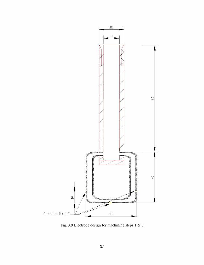
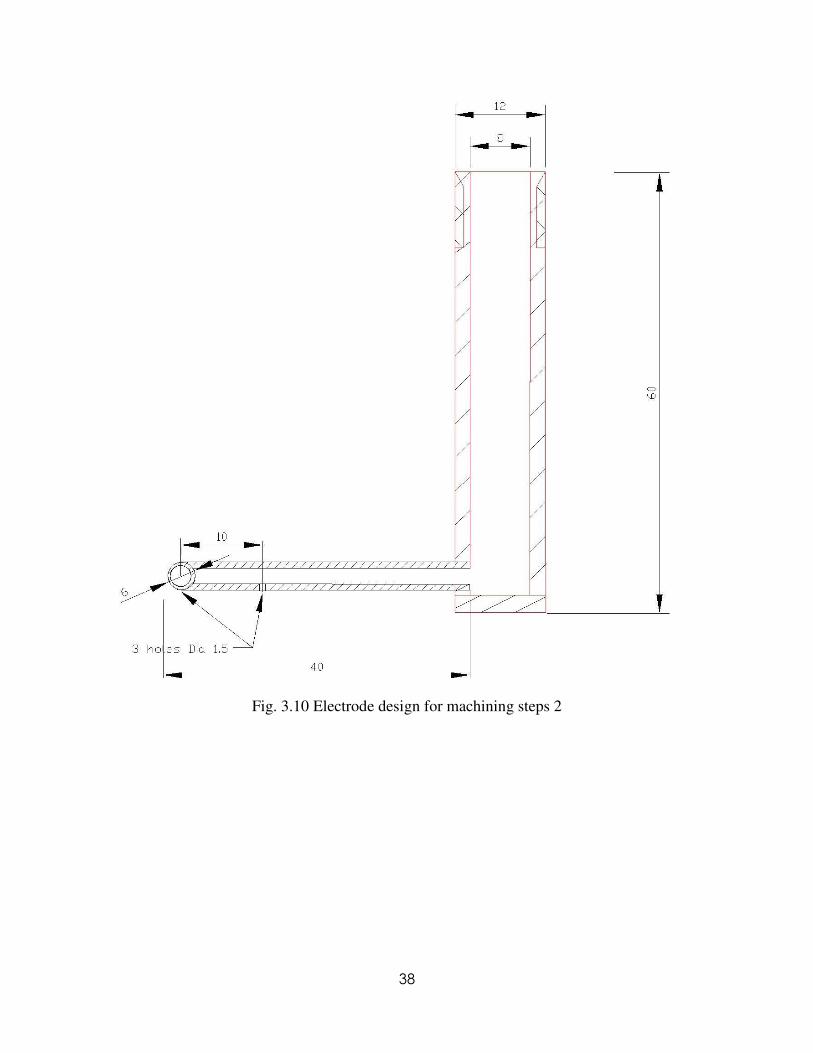
3.5 DESIGN OF ELECTRODE:
In ECM generally tool which is cathode, is made out of non reacting material such as Copper.
We want to study the tool design problem in ECM, only to determine a cathode shape which will
machine a specified work piece shape.
In this experiment we have taken cupper as electrode material at cathode. It is designed in U
shape so as to cut the cavity in AISI D2 steel in the similar profile. A long hollow cupper pipe
was taken having length of 70mm. The internal and external dia of that cupper pipe was taken
8mm and 12 mm respectively. In one side of the copper pipe a thread was done up to 10mm with
the help of threading die for M12 thread. After that a through hole is made by the help of drilling
machine up to 60mm from the threading point. The pith of the thread was kept 2mm.From the
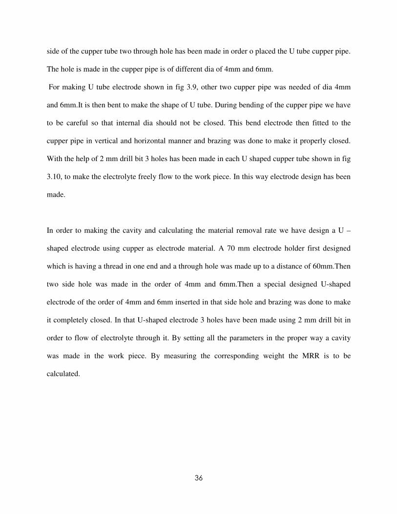
36
side of the cupper tube two through hole has been made in order o placed the U tube cupper pipe.
The hole is made in the cupper pipe is of different dia of 4mm and 6mm.
For making U tube electrode shown in fig 3.9, other two cupper pipe was needed of dia 4mm
and 6mm.It is then bent to make the shape of U tube. During bending of the cupper pipe we have
to be careful so that internal dia should not be closed. This bend electrode then fitted to the
cupper pipe in vertical and horizontal manner and brazing was done to make it properly closed.
With the help of 2 mm drill bit 3 holes has been made in each U shaped cupper tube shown in fig
3.10, to make the electrolyte freely flow to the work piece. In this way electrode design has been
made.
In order to making the cavity and calculating the material removal rate we have design a U –
shaped electrode using cupper as electrode material. A 70 mm electrode holder first designed
which is having a thread in one end and a through hole was made up to a distance of 60mm.Then
two side hole was made in the order of 4mm and 6mm.Then a special designed U-shaped
electrode of the order of 4mm and 6mm inserted in that side hole and brazing was done to make
it completely closed. In that U-shaped electrode 3 holes have been made using 2 mm drill bit in
order to flow of electrolyte through it. By setting all the parameters in the proper way a cavity
was made in the work piece. By measuring the corresponding weight the MRR is to be
calculated.
37
Fig. 3.9 Electrode design for machining steps 1 & 3
38
Fig. 3.10 Electrode design for machining steps 2

39
Fig. 3.11 U-Shaped tubular electrode of dia 4mm & 6 mm for machining step 2
Fig. 3.12 U-Shaped tubular electrode of dia 4mm & 6 mm for machining step 1 & 3
3.6 Taguchi Design:
Prof. Genichi Taguchi, a Japanese engineer, proposed several approaches to experimental
designs that are sometimes called "Taguchi Methods." These methods utilize two-, three-, and
mixed-level fractional factorial designs. Taguchi refers to experimental design as "off-line
quality control" because it is a method of ensuring good performance in the design stage of

40
products or processes. The aim here is to make a product or process less variable (more robust)
in the face of variation over which we have little or no control.
Table- 3.4 Factor levels
Levels Feed mm/min Flow Rate L/min Dia mm K mS/cm
1. 0.21 3 4 63
2. 0.32 6 6 118
3. 0.45
4. 0.54
Table 3.5 L8 orthogonal array
Run A-Feed mm/min B-Flow Rate
L/min
C-Dia mm D-Conductivity
mS/cm
1 1 1 1 2
5 1 2 2 1
2 2 1 1 1
6 2 2 2 2
3 3 2 1 2
7 3 1 2 1
4 4 2 1 1
8 4 1 2 2
41
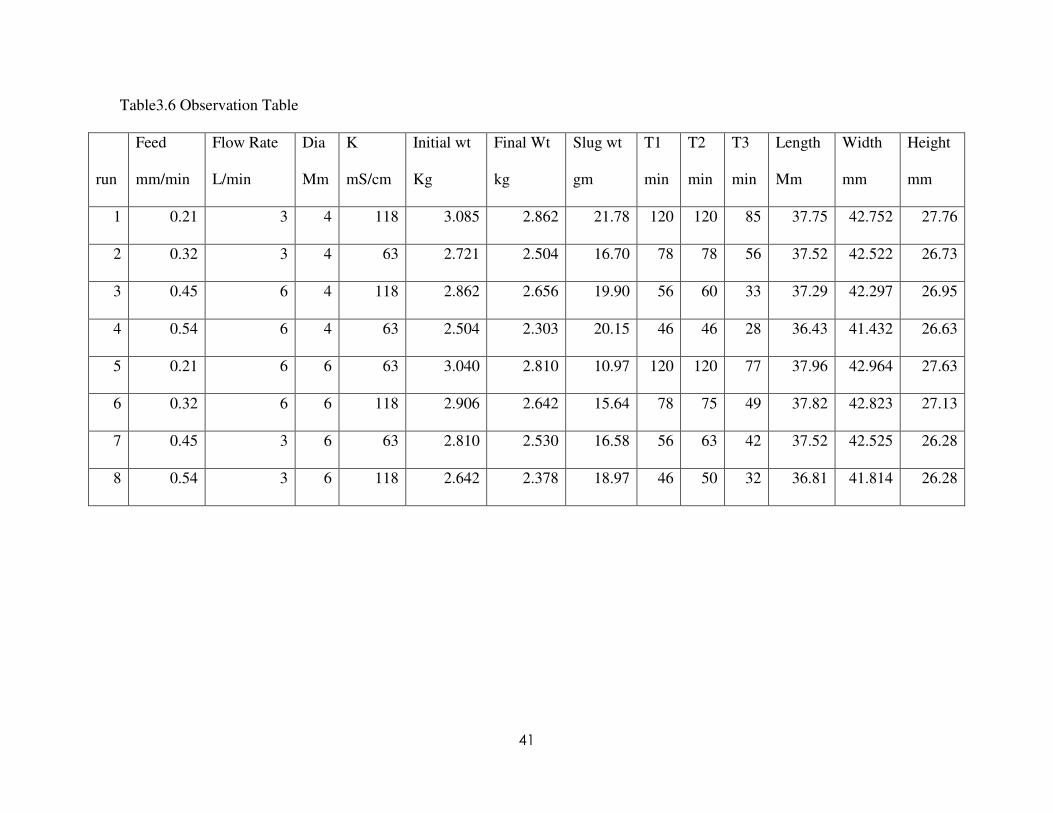
Table3.6 Observation Table
run
Feed
mm/min
Flow Rate
L/min
Dia
Mm
K
mS/cm
Initial wt
Kg
Final Wt
kg
Slug wt
gm
T1
min
T2
min
T3
min
Length
Mm
Width
mm
Height
mm
1 0.21 3 4 118 3.085 2.862 21.78 120 120 85 37.75 42.752 27.76
2 0.32 3 4 63 2.721 2.504 16.70 78 78 56 37.52 42.522 26.73
3 0.45 6 4 118 2.862 2.656 19.90 56 60 33 37.29 42.297 26.95
4 0.54 6 4 63 2.504 2.303 20.15 46 46 28 36.43 41.432 26.63
5 0.21 6 6 63 3.040 2.810 10.97 120 120 77 37.96 42.964 27.63
6 0.32 6 6 118 2.906 2.642 15.64 78 75 49 37.82 42.823 27.13
7 0.45 3 6 63 2.810 2.530 16.58 56 63 42 37.52 42.525 26.28
8 0.54 3 6 118 2.642 2.378 18.97 46 50 32 36.81 41.814 26.28

42
Fig 3.13 Work piece after machining for run 1 and 2
Fig 3.14work piece after machining for run 3and 4

43
Fig 3.15work piece after machining run 5 and 6
Fig 3.16 work piece after machining run 7and 8
44
3.7 Sample Calculation
MRR is calculated as given by the following formula
321 TTT
wtfinalwtInitialMRR
++
−= (3.1)
MRR effective is calculated as given by the following formula
321 TTT
wtSlugwtfinalwtInitialeffectiveMRR
++
+−= (3.2)
Over-cut, GL is calculated as given by the following formula
2
35
2
−=
−=
lengthlengthcutlengthGL (3.3)
Over-cut, GW is calculated as given by the following formula
2
40
2
−=
−=
widthwidthcutwidthGW (3.4)
Over-cut, GH is calculated as given by the following formula
2
25
2
−=
−=
heightheightcutheightGH (3.5)
Sample calculation for observation no 1 (run 1) is presented below and the results are shown in
Table 3.6
0.69615485120120
2.862-3.085=
++=MRR (3.6)
MRR effective is calculated as given by the following formula
0.76316985120120
21.78/1000-2.862-3.085=
++=effectiveMRR (3.7)
Over-cut, GL is calculated as given by the following formula

45
1.3752
35-37.75==GL (3.8)
Over-cut, GW is calculated as given by the following formula
376.12
40-42.752==GW (3.9)
Over-cut, GH is calculated as given by the following formula
380.1252
27.76=−=GH (3.10)
46
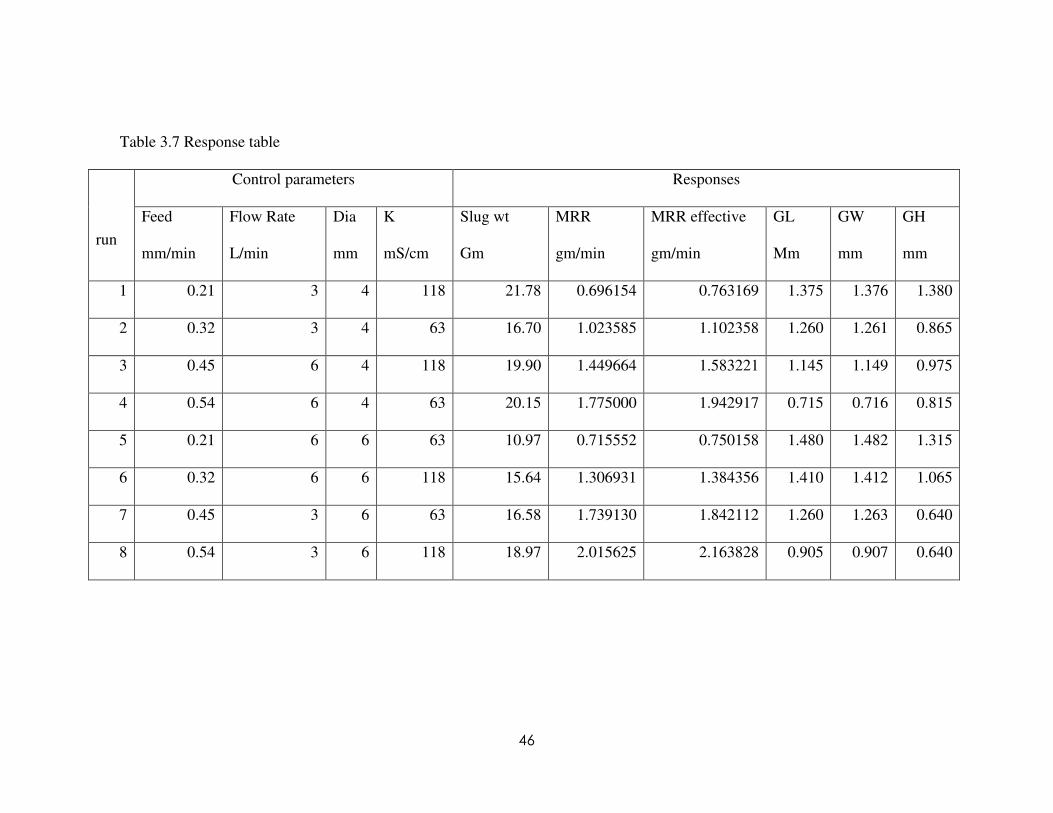
Table 3.7 Response table
Control parameters Responses
run
Feed
mm/min
Flow Rate
L/min
Dia
mm
K
mS/cm
Slug wt
Gm
MRR
gm/min
MRR effective
gm/min
GL
Mm
GW
mm
GH
mm
1 0.21 3 4 118 21.78 0.696154 0.763169 1.375 1.376 1.380
2 0.32 3 4 63 16.70 1.023585 1.102358 1.260 1.261 0.865
3 0.45 6 4 118 19.90 1.449664 1.583221 1.145 1.149 0.975
4 0.54 6 4 63 20.15 1.775000 1.942917 0.715 0.716 0.815
5 0.21 6 6 63 10.97 0.715552 0.750158 1.480 1.482 1.315
6 0.32 6 6 118 15.64 1.306931 1.384356 1.410 1.412 1.065
7 0.45 3 6 63 16.58 1.739130 1.842112 1.260 1.263 0.640
8 0.54 3 6 118 18.97 2.015625 2.163828 0.905 0.907 0.640

47
3.8 CONCLUSION
Experiments were conducted according to Taguchi method by using the machining set up and the
designed U-shaped tubular electrodes. The control parameters like feed, diameter of electrode,
flow rate, and conductivity were varied to conduct 8 different experiments and the weights of the
work piece and dimensional measurements of the cavity were taken for calculation of MRR and
over cuts.
48
Chapter 4Chapter 4Chapter 4Chapter 4 RESULTS AND DISCUSSIONRESULTS AND DISCUSSIONRESULTS AND DISCUSSIONRESULTS AND DISCUSSION
Introduction
In this chapter, the responses such as MRR, MRR effective, slug wt and various over-cuts are
calculated from the observation table, which are analyses and discussed.
4.1 ANALYSIS OF EXPERIMENT AND DISCUSSION:
Effect on MRR and effective MRR
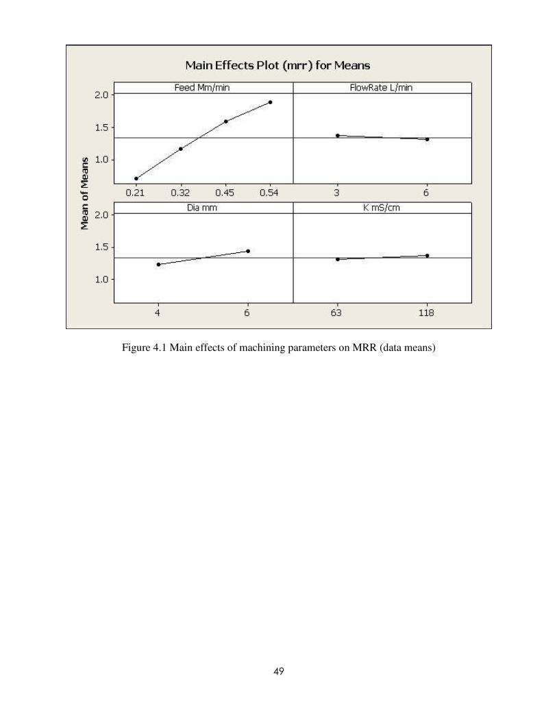
The machinability of ECM depends on the electrical conductivity of the electrolyte, feed rate of
electrode, inter electrode gap and electrolyte flow rate [27, 3]. The influence of various
machining parameters on MRR (means) are shown in Fig. 4.1. The electrode feed rate has
enormous effect on MRR and it increases with increase in feed rate. This result was expected
because the material removal rate increases with feed rate because the machining time decreases.
MRR also increases with larger diameter of electrode; however, the effect is less than the feed
rate on MRR. The electrolyte flow rate and conductivity has very little effect on MRR and
doesn’t give any conclusive evidence of any impact on MRR. Similar trends are shown by the
plot of main effects for SN ratios on MRR in Fig.4.2. In Table 4.2, the main effects of feed,
diameter of electrode, flow rate, conductivity are 1.1895, 0.2082, 0.0568 and 0.0538,
respectively, on MRR in gm/min, in order of significance. These results are in good agreement
with the observations of many researchers.
49
Figure 4.1 Main effects of machining parameters on MRR (data means)

50
Figure 4.2 Main effects of machining parameters on MRR (SN ratios)
Table 4.1 Taguchi analysis response table for MRR: larger is better
Level Feed Mm/min Flow Rate L/min Dia mm K mS/cm
SN ratios 1 -3.027 1.988 1.316 1.771
2 1.264 1.907 2.578 2.123
3 4.016
4 5.536
Delta 8.563 0.081 1.262 0.352
Rank 1 4 2 3
Means 1 0.7059 1.3686 1.2361 1.3133
2 1.1653 1.3118 1.4443 1.3671
3 1.5944
4 1.8953
Delta 1.1895 0.0568 0.2082 0.0538
Rank 1 3 2 4

51
Figure 4.3 Scatter plot of MRR effective, MRR vs. feed for various electrode diameters.
Since, MRR effective is always more than MRR, for positive slug weight, the graph in Fig 4.3
shows that with feed, both the MRR’s increases. The effect of electrode diameter on MRR
effective is obvious as the projected area of electrode having fewer diameters is less than that of
larger diameter electrode; the actual material removed under the projected area is less. Thus, with
smaller electrode diameter, similar sized cavity can be made with lesser amount of material
removed and saving energy. The influence of various machining parameters on MRR effective
(means) are shown in Fig. 4.4. The electrode feed rate has enormous effect on MRR effective
and it increases with increase in feed rate. MRR effective also increases with larger diameter of
electrode; however, the effect is less than the feed rate on MRR effective. The electrolyte flow
rate and conductivity has very little effect on MRR and doesn’t give any conclusive evidence of
any impact on MRR. Similar trends are shown by the plot of main effects for SN ratios on MRR
effective in Fig.4.5. In Table 4.3, the main effects of feed, diameter of electrode, flow rate,
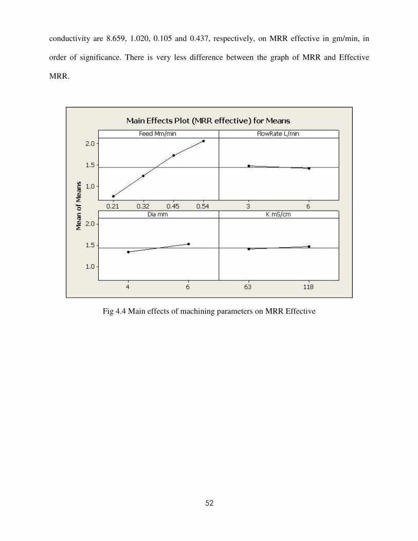
52
conductivity are 8.659, 1.020, 0.105 and 0.437, respectively, on MRR effective in gm/min, in
order of significance. There is very less difference between the graph of MRR and Effective
MRR.
Fig 4.4 Main effects of machining parameters on MRR Effective

53
Fig 4.5 Main effects of machining parameters on MRR effective (SN ratios)
Table-4.2 Taguchi analysis response table for MRR effective: larger is better
Level Feed Mm/min Flow Rate L/min Dia mm K mS/cm
SN ratios 1 -2.422 2.627 2.065 2.356
2 1.836 2.522 3.085 2.793
3 4.649
4 6.237
Delta 8.659 0.105 1.020 0.437
Rank 1 4 2 3
Means 1 0.7567 1.4679 1.3479 1.4094
2 1.2434 1.4152 1.5351 1.4736
3 1.7127
4 2.0534
Delta 1.2967 0.0527 0.1872 0.0643
Rank 1 4 2 3
54
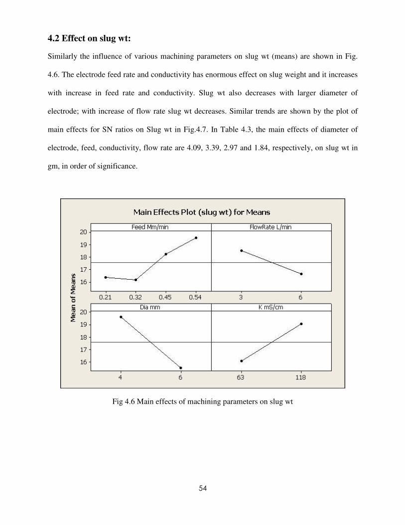
4.2 Effect on slug wt:
Similarly the influence of various machining parameters on slug wt (means) are shown in Fig.
4.6. The electrode feed rate and conductivity has enormous effect on slug weight and it increases
with increase in feed rate and conductivity. Slug wt also decreases with larger diameter of
electrode; with increase of flow rate slug wt decreases. Similar trends are shown by the plot of
main effects for SN ratios on Slug wt in Fig.4.7. In Table 4.3, the main effects of diameter of
electrode, feed, conductivity, flow rate are 4.09, 3.39, 2.97 and 1.84, respectively, on slug wt in
gm, in order of significance.
Fig 4.6 Main effects of machining parameters on slug wt
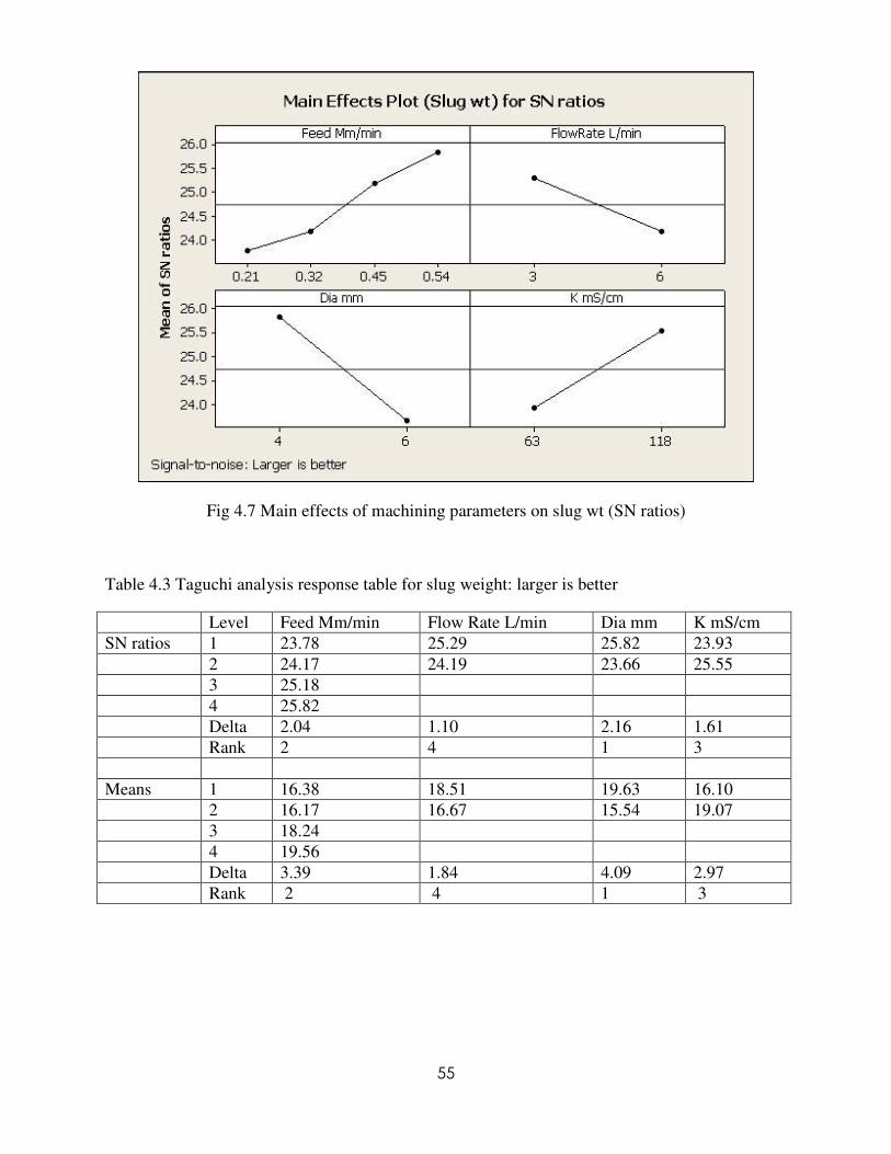
55
Fig 4.7 Main effects of machining parameters on slug wt (SN ratios)
Table 4.3 Taguchi analysis response table for slug weight: larger is better
Level Feed Mm/min Flow Rate L/min Dia mm K mS/cm
SN ratios 1 23.78 25.29 25.82 23.93
2 24.17 24.19 23.66 25.55
3 25.18
4 25.82
Delta 2.04 1.10 2.16 1.61
Rank 2 4 1 3
Means 1 16.38 18.51 19.63 16.10
2 16.17 16.67 15.54 19.07
3 18.24
4 19.56
Delta 3.39 1.84 4.09 2.97
Rank 2 4 1 3

56
4.3 Effect on over cut (GL):
One of the major challenges in ECM is the control of the cavity oversize (or over cut). Over cut
depends on the characteristics of electrolyte, e.g. concentration, flow rate, and its throwing power
and sludge formation. In the machining area, just below the machining face of the tool, anodic
reaction rate and conductivity of the electrolyte is constant. Away from the main machining
zone, current density decreases asymptotically to zero with increasing distance along the work
piece surface. Up to a certain distance, current density is sufficient for metal dissolution, which
causes over cut. Due to the increase in electrolyte concentration, ions associated with the
machining operation in the machining zone also increase. A Higher concentration of ions reduces
the localization effect of electrochemical material removal reactions. This leads to the higher
over cut of the work piece and thus reduces the machining accuracy. Removal of material by the
stray current increases with the increase of electrolyte concentration. This stray current effect is
more predominant at higher concentrations of electrolyte. Electrolyte temperature directly affects
the conductivity of the electrolyte. A temperature increase results in over cut increase up to the
point at which the electrolyte vaporizes in the machining gap [24].
The effect of various machining parameters on over cut GL (means) are shown in Fig.4.8. The
electrode feed rate has enormous effect on length over cut and it decreases with increase in feed
rate. It is due to the fact that with increasing feed rate, the machining of cavity neighborhood is
reduced. Over cut GL also increases with larger diameter of electrode. The electrolyte flow rate
and conductivity has very little effect on length over cut and doesn’t give any conclusive
evidence of any impact on length over cut. But the main effect of parameter on SN ratio on over
cut is varying. With increase of feed rate over cut of length increases. But with increases of
electrode dia length over cut decreases. Effect of conductivity and flow rate is very less. In Table
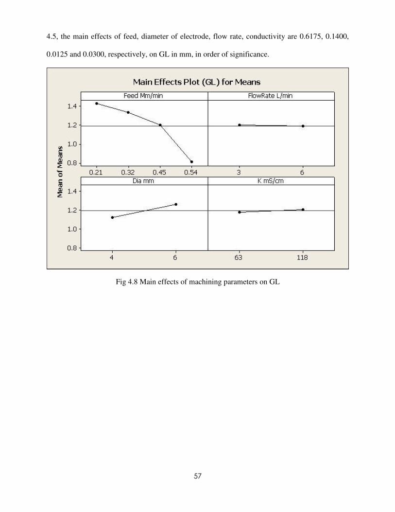
57
4.5, the main effects of feed, diameter of electrode, flow rate, conductivity are 0.6175, 0.1400,
0.0125 and 0.0300, respectively, on GL in mm, in order of significance.
Fig 4.8 Main effects of machining parameters on GL

58
Fig 4.9 Main effects of machining parameters on GL(SN ratio)
Table 4.4 Taguchi analysis response table for GL: smaller is better
Level Feed Mm/min Flow Rate L/min Dia mm K mS/cm
SN ratios 1 -3.0856 -1.4785 -0.7589 -1.1265
2 -2.4959 -1.1630 -1.8825 -1.5149
3 -1.5918
4 1.8905
Delta 4.9761 0.3155 1.1236 0.3883
Rank 1 4 2 3
Means 1 1.4275 1.200 1.1238 1.1788
2 1.3350 1.1875 1.2638 1.2088
3 1.2025
4 0.8100
Delta 0.6175 0.0125 0.1400 0.0300
Rank 1 4 2 3

59
4.4Effect on overcut (GW):
The influence of various machining parameters on Width over cut, GW (means) are shown in
Fig. 5.0. The electrode feed rate has enormous effect on width over cut and it decreases with
increase in feed rate. Width over cut also increases with larger diameter of electrode. The
electrolyte flow rate and conductivity has very little effect on width over cut. Similarly width
over cut increases significantly with increase of feed rate. Width over cut also gradually
decreases with increase of diameter of the electrode. Effect of flow rate and conductivity has
very little effect on width over cut. Trends are shown by the plot of main effects for SN ratios
on width over cut in Fig.5.1. In Table 4.6 the main effects of feed, diameter of electrode, flow
rate, conductivity are 0.6175, 0.1404, 0.0121 and 0.0304, respectively, on width over cut in mm,
in order of significance.
Figure 4.10 Main effects of machining parameters on GW
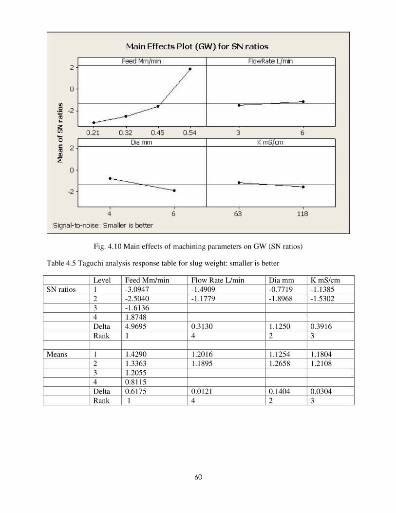
60
Fig. 4.10 Main effects of machining parameters on GW (SN ratios)
Table 4.5 Taguchi analysis response table for slug weight: smaller is better
Level Feed Mm/min Flow Rate L/min Dia mm K mS/cm
SN ratios 1 -3.0947 -1.4909 -0.7719 -1.1385
2 -2.5040 -1.1779 -1.8968 -1.5302
3 -1.6136
4 1.8748
Delta 4.9695 0.3130 1.1250 0.3916
Rank 1 4 2 3
Means 1 1.4290 1.2016 1.1254 1.1804
2 1.3363 1.1895 1.2658 1.2108
3 1.2055
4 0.8115
Delta 0.6175 0.0121 0.1404 0.0304
Rank 1 4 2 3

61
4.5 Effect on over cut (GH):
The influence of various machining parameters on height over cut, GH (means) are shown in
Fig5.2. The electrode feed rate has enormous effect on height over cut and it gradually decreases
increase in feed rate. Height over cut also increases with flow rate and conductivity. But height
over cut decrease with increase of diameter of the electrode. Main effects for SN ratios height
over cut are shown in Fig.5.3.The height over cut is gradually increases with increase of feed rate
and diameter of the electrode. But with increases of conductivity and flow rate the height over
cut decreases In Table 4.7 the main effects of feed, diameter of electrode, flow rate, conductivity
are 0.6200, 0.0938, 0.1612 and 0.1063, respectively, on height over cut in mm, in order of
significance.
Fig 4.12 Main effects of machining parameters on GH

62
Fig 4.13 Main effects of machining parameters on GH (SN ratios)
Table 4.6 Taguchi analysis response table for slug weight: smaller is better
Level Feed Mm/min Flow Rate L/min Dia mm K mS/cm
SN ratios 1 -2.5880 1.5537 0.1147 1.1336
2 0.9650 1.0425 0.9150 1.0150
3 2.0486
4 2.8266
Delta 5.4147 1.7859 1.0921 0.9475
Rank 1 2 3 4
Means 1 1.3475 0.8813 1.0088 0.9088
2 0.9650 1.0425 0.9150 1.0150
3 0.8075
4 0.7275
Delta 0.6200 0.1612 0.0938 0.1063
Rank 1 2 4 3
Table 4.7 shows the ANOVA results of over cut GL and feed and diameter of electrode are
found to be significant. The linear model has R2 fit value of 99.98 and R
2(Adj) fit value of 99.84

63
which justify that the two significant factors contribute mostly for over cut GL. Similarly, in
Table 4.8 and 4.9, the ANOVA tables for over cut GW and GH, respectively, are presented.
These tables show that the feed and diameter are significant factors for controlling over cut.
Table 4.7 Analysis of Variance for GL
Source DF SeqSS AdjSS AdjMS F P
Feed 3 0.443863 0.443863 0.147954 1315.15 0.020
Flow Rate 1 0.000313 0.000313 0.000313 2.78 0.344
Dia 1 0.039200 0.039200 0.039200 348.44 0.034
K 1 0.001800 0.001800 0.001800 16.00 0.156
Error 1 0.000113 0.000113 0.000113
Total 7 0.485288
S = 0.0106066 R-Sq = 99.98% R-Sq(adj) = 99.84%
Table 4.8 Analysis of Variance for GW
Source DF SeqSS AdjSS AdjMS F P
Feed 3 0.443778 0.443778 0.147926 1120.39 0.022
Flow Rate 1 0.000294 0.000294 0.000294 2.23 0.376
Dia 1 0.039410 0.039410 0.039410 298.49 0.037
K 1 0.001845 0.001845 0.001845 13.98 0.166
Error 1 0.000132 0.000132 0.000132
Total 7 0.485459
S = 0.0114905 R-Sq = 99.97% R-Sq(adj) = 99.81%
Table 4.9 Analysis of Variance for GH
Source DF SeqSS AdjSS AdjMS F P
Feed 3 0.454959 0.454959 0.151653 110.04 0.070
Flow Rate 1 0.052003 0.052003 0.052003 37.73 0.103
Dia 1 0.017578 0.017578 0.017578 12.76 0.174
K 1 0.022578 0.022578 0.022578 16.38 0.154
Error 1 0.001378 0.001378 0.001378
Total 7 0.548497
S = 0.0371231 R-Sq = 99.75% R-Sq(adj) = 98.24%
Conclusion
The work evaluates the feasibility of machining blind cavity on AISI D2 tool steel in ECM with
U-shaped electrode. The performance parameters like MRR, MRR effective, slug weight and
64
various over cuts are studied under various machining parameters. The most significant factors
for MRR and MRR effective are found to be feed and diameter of electrode. Both the response
increases with increase in feed and electrode diameter. Furthermore, the flow rate and
electrolyte concentration has very little effect. The feed has positive effects the slug weight and
diameter of electrode is inversely proportional to slug weight. The over cuts GL, GW, GH are
influenced by feed and diameter of electrode. With feed over cuts reduce and diameter of
electrode tends to increase the over cuts.
65
Chapter 5Chapter 5Chapter 5Chapter 5 CONCLUSIONCONCLUSIONCONCLUSIONCONCLUSION
The present work is an attempt to study the feasibility of machining blind cavity on AISI D2 tool
steel in ECM with U-shaped electrode. The MRR, MRR effective, slug weight and various over
cuts are studied with various setting of electrode feed rate, electrolyte flow rate, electrolyte
concentration and diameter of electrode. The most significant factors for MRR and MRR
effective are found to be feed and diameter of electrode. Both the response increases with
increase in feed and electrode diameter. Furthermore, the flow rate and electrolyte concentration
has very little effect. The feed has positive effects the slug weight and diameter of electrode is
inversely proportional to slug weight. The over cuts along length, width and height of cavity are
influenced by feed and diameter of electrode. All these over cuts reduce with increase in feed
and diameter of electrode tends to increase the over cuts.

66
Chapter 6Chapter 6Chapter 6Chapter 6 REFERENCES:REFERENCES:REFERENCES:REFERENCES:
1 B. Bhattacharyya, M. Malapati, J. Munda, A. Sarkar Influence of tool vibration on machining
performance in electrochemical micro-machining of copper International Journal of Machine
Tool and Manufacture 47 (2007) 335–342.
2 Liu JW, Yue TM, Guo ZN. Wire electrochemical discharge machining of Al2O3 particl
reinforced aluminum alloy 6061. Mater Manufacturing Process 2009; 24(4):446-53.
3 Jo ao Cirilo da Silva Neto, Evaldo Malaquias da Silva , Marcio Bacci da Silva Intervening
variables in electrochemical machining Journal of Materials Processing Technology 179 (2006)
92–96.
4 Sekar T, Marappan R. Experimental investigations into the influencing parameters of
electrochemical machining of AISI 202. Journal of Advanced Manufacturing Systems 2008;
7(2):337-43.
5 S KMukherjee, S Kumar, and P K Srivastava Effect of electrolyte on the current- carrying
process in electrochemical machining Proc. I Mech E Vol. 221 Part C: J. Mechanical
Engineering Science.
6 Neto JCdS, Silva EMd, Silva MBd. Intervening variables in electrochemical machining. J Mater
Process Technol 2006; 179(1-3):92-6.
7 Bhattacharyya B, Munda J. Experimental investigation on the influence of electrochemical
machining parameters on machining rate and accuracy in micromachining domain. Int J Mach
Tools Manuf 2003; 43(13):1301-10.
8 K. P. Rajurkar, B. Wei, .c. L. Schnacker Monitoring and Control of Electrochemical Machining
(ECM)Journal of Engineering for Industry May 1993, Vol. 115/217.

67
9 S.K. Mukherjee, S. Kumar, P.K. Srivastava, Arbind Kumar Effect of valance on material
removal rate in electrochemical machining of aluminum journal of materials processing
technology 2 0 2 ( 2 00 8 ) 398–401.
10 V.K. Jain, S. Adhikary On the mechanism of material removal in electrochemical spark
machining of quartz under different polarity conditions journal of materials processing
technology 2 0 0 ( 2 0 0 8 ) 460–470 .
11 K.L. Bhondwe, Vinod Yadava, G. Kathiresan Finite element prediction of material removal rate
due to electro-chemical spark machining International Journal of Machine Tools & Manufacture
46 (2006) 1699–1706.
12 S.K. Mukherjee, S. Kumar, P.K. Srivastava, Arbind Kumar Effect of valence on material
removal rate in electrochemical machining of aluminum journal of materials processing
technology 2 0 2 ( 2 0 0 8 ) 398–401.
13 V.K. Jain, P.M. Dixit, P.M. Pandey On the analysis of the electrochemical spark machining
process International Journal of Machine Tools & Manufacture 39 (1999) 165–186.
14 R V Rao, P J Pawar, and R Shankar Multi-objective optimization of electrochemical machining
process parameters using a particle swarm optimization algorithm Proc. I Mech Vol. 222 Part B:
J. Engineering Manufacture.
15 B. Bhattacharyya, S.K. Sorkhel Investigation for controlled electrochemical machining through
response surface methodology-based approach Journal of Materials Processing Technology 86
(1999) 200–207.
16 Yuming Zhou and Jeffrey J. Derby The cathode design problem in Chemical Engineering
Science, Vol. 50, No. 17, pp. 2679 2689, 1995.

68
17 H. Hocheng, Y.H. Sun, S.C. Lin, P.S. Kao A material removal analysis of electrochemical
machining using flat-end cathode Journal of Materials Processing Technology 140 (2003) 264–
268.
18 Anjali V. Kulkarni and V. K. Jain Micro fabrication using Electrochemical Spark Mechanical
Engineering Department Indian Institute of Technology, Kanpur-208016.
19 S. K. Mukherjee, S. Kumar and P. K. Srivastava effect of Over Voltage on Material Removal
Rate during Electrochemical Machining Journal of Science and Engineering, Vol. 8, No 1, pp.
23-28 (2005).
20 A. K. M. De Silva, H. S. J. Altena, J. A. McGeough Precision ECM by Process Characteristic
Modeling Journals of precession engineering.
21 K.L. Bhondwe, Vinod Yadav, G. Kathiresan Finite element prediction of material removal rate
due to electro-chemical spark machining International Journal of Machine Tools & Manufacture
46 (2006) 1699–1706.
22 Jerzy Kozak, Kamlakar P. Rajurkar, Yogesh Makkar Selected problems of micro-
electrochemical machining Journal of Materials Processing Technology 149 (2004) 426–431.
23 K.P. Rajurkar , D.Zhu, J.A. McGeough , J. Kozak, A. De Silva New Developments in Electro-
Chemical Machining research paper.
24 Mohan Sen., H.S. Shan A review of electrochemical macro- to micro-hole drilling processes
International Journal of Machine Tools & Manufacture 45 (2005) 137–152.
25 B. H. Kim, C. W. Na, Y. S. Lee, D. K. Choi, C. N. Chu Micro Electrochemical Machining of 3D
Micro Structure Using Dilute Sulfuric Acid research paper.
26 Jerzy Kozak, Kamlakar P. Rajurkar , Yogesh Makkarb Selected problems of micro-
electrochemical machining Journal of Materials Processing Technology 149 (2004) 426–431.

69
27 M.S. Hewidy, S.J. Ebeid, T.A. El-Taweel, A.H. Youssef Modeling the performance of ECM
assisted by low frequency vibrations Journal of Materials Processing Technology 189 (2007)
466–472.
28 M. Kock, V. Kirchner, R. Schuster Electrochemical micromachining with ultra short voltage
pulses a versatile method with lithographical precision Electrochemical Acta 48 (2003)
3213/3219.
29 Se Hyun Ahn, Shi Hyoung Ryu, Deok Ki Choi , Chong Nam Chu Electro-chemical micro
drilling using ultra short pulses journals of Precision Engineering 28 (2004) 129–134.
30 Chunhua Suna, Di Zhu, Zhiyong Li, LeiWang Application of FEM to tool design for
electrochemical machining freeform surface journals of Finite Elements in Analysis and Design
43 (2006) 168 – 172.
31 J.A. Westley , J. Atkinson , A. Duffield Generic aspects of tool design for electrochemical
machining Journal of Materials Processing Technology 149 (2004) 384–392.
32 Kurita, T., Endo, C., Matsui, Y., Masuda, H., Terasawa, K., Tanaka, F., Ikeda, H., Oguchi, K.,
Kobayashi, K.; Mechanical/electrochemical complex machining method for efficient, accurate,
and environmentally benign process; International Journal of Machine Tools and Manufacture;
2008; 48; 15; 1599; 1604
33 Shin, H.S., Kim, B.H., Chu, C.N.; Analysis of the side gap resulting from micro electrochemical
machining with a tungsten wire and ultra short voltage pulses; Journal of Micromechanics and
Micro engineering; 2008; 18; 7;
34 Mount, A.R., Muir, R.N.; Dissolution characteristics of iron and stainless steels in chloride
under electrochemical machining conditions; Journal of the Electrochemical Society; 2007; 154;
3; E57; E61
70
35 Kurita, T., Hattori, M.; A study of EDM and ECM/ECM-lapping complex machining technology;
International Journal of Machine Tools and Manufacture; 2006; 46; 14; 1804; 1810
36 Neto, J.C.d.S., Silva, E.M.d., Silva, M.B.d.; Intervening variables in electrochemical machining;
Journal of Materials Processing Technology; 2006; 179; 39873; 92; 96
37 Hocheng, H., Kao, P.S., Lin, S.C.; Development of the eroded opening during electrochemical
boring of hole; International Journal of Advanced Manufacturing Technology; 2005; 25; 40158;
1105; 1112.
38 Jiawen, X., Naizhang, Y., Yangxin, T., Rajurkar, K.P.; The modelling of NC-electrochemical
contour evolution machining using a rotary tool-cathode; Journal of Materials Processing
Technology; 2005; 159; 2; 272; 277
39 Hewidy, M.S., Ebeid, S.J., Rajurkar, K.P., El-Safti, M.F.; Electrochemical machining under
orbital motion conditions; Journal of Materials Processing Technology; 2001; 109; 3; 339; 346.
40 Ruszaj, A., Zybura-Skrabalak, M.; Mathematical modelling of electrochemical machining with
flat ended universal electrodes; Journal of Materials Processing Technology; 2001; 109; 3; 333;
338
41 Kozak, J.; Computer simulation system for electrochemical shaping; Journal of Materials
Processing Technology; 2001; 109; 3; 354; 359
42 Bogoveev, N.A., Firsov, A.G., Filatov, E.I., Tikhonov, A.S.; Computer support for `all-round'
ECM processing of blades; Journal of Materials Processing Technology; 2001; 109; 3; 324; 326
43 Chang, C.S., Hourng, L.W.; Two-dimensional two-phase numerical model for tool design in
electrochemical machining; Journal of Applied Electrochemistry; 2001; 31; 2; 145; 154.

71
CHAPTER 7CHAPTER 7CHAPTER 7CHAPTER 7 Bibliography:Bibliography:Bibliography:Bibliography:
[1] www.sciencedirect.com
[2] www.scopus.com
[3] www.efunda.com
[4] www.google.com
[5] Production Engineering Technology book by R.K Jain.
[6] Meta-tech ECM manual
[7] www.nitrkl.ac.in