estimation and compensation of inter carrier interference in - aircc
TRANSCRIPT
International Journal of Next-Generation Networks (IJNGN) Vol.4, No.3,September 2012
DOI : 10.5121/ijngn.2012.4306 73
ESTIMATION AND COMPENSATION OF INTER
CARRIER INTERFERENCE IN WIMAX PHYSICAL
LAYER UNDER VARIOUS CHANNEL MODELS
Tarun Kumar Juluru1 and Anitha sheela Kankacharla
2
1 Sumathi Reddy Institute of Technology For Women, Warangal,
Andhra Pradesh, India. [email protected]
2 Department of ECE, JNTU College of Engineering, Hyderabad,
Andhra Pradesh, India. [email protected]
ABSTRACT
WiMAX is Wireless Interoperability for Microwave Access has emerged as a promising solution for
transmission of higher data rates for fixed and mobile applications. IEEE 802.16d and e are the standards
proposed by WiMAX group for fixed and mobile. As the wireless channel have so many limitation Such as
Multipath, Doppler spread, Delay spread and Line Of Sight (LOS)/Non Line Of Sight (NLOS) components.
To attain higher data rates the Multi Carrier System with Multiple Input and Multiple Output (MIMO) is
incorporated in the WiMAX. The Orthogonal Frequency Division Multiplexing (OFDM) is a multi carrier
technique used with the WiMAX systems. In OFDM the available spectrum is split into numerous narrow
band channels of dissimilar frequencies to achieve high data rate in a multi path fading environment. And
all these sub carriers are considered to be orthogonal to each other. As the number of sub carriers is
increased there is no guarantee of sustained orthogonality, i.e. at some point the carriers are not
independent to each other, and hence where the orthogonality can be loosed which leads to interference
and also owing to the synchronization between transmitter and receiver local oscillator, it causes
interference known as Inter Carrier Interference (ICI). The systems uses MIMO-OFDM will suffer with the
effects of ICI and Carrier Frequency Offset (CFO) “ε”. However these affect the power leakage in the
midst of sub carriers, consequently degrading the system performance. In this paper a new approach is
proposed in order to reduce the ICI caused in WiMAX and improve the system performance. In this scheme
at the transmitter side the modulated data and a few predefined pilot symbols are mapped onto the non
neighboring sub carriers with weighting coefficients of +1 and -1. With the aid of pilot symbols the
frequency offset is exactly estimated by using Maximum Likelihood Estimation (MLE) and hence can be
minimized. At demodulation stage the received signals are linearly combined along with their weighted
coefficients and pilot symbols, called as Pilot Aided Self Cancellation Method (PASCS). And also to realize
the various wireless environments the simulations are carried out on Stanford University Interim (SUI)
channels. The simulation results shows that by incorporating this method into WiMAX systems it performs
better when the Line Of Sight (LOS) component is present in the transmission and also it improves the Bit
Error Rate (BER) and Carrier to Interference Ratio (CIR). The CIR can be improved 20 dB. In this paper
the effectiveness of PASCS scheme is compared with the Self Cancellation Method (SCM). It provides
accurate estimation of frequency offset and when residual CFO is less significant the ICI can be diminished
successfully.
KEYWORDS
Inter Carrier Interference (ICI), OFDM, Pilot Aided Self Cancellation, SUI channels, WiMAX.
International Journal of Next-Generation Networks (IJNGN) Vol.4, No.3,September 2012
74
1. INTRODUCTION
Worldwide interoperability for microwave access IEEE802.16 is a standard proposed by WiMAX
group. 802.16d is for fixed networks and e for mobile broadband networks. The physical layer of
WiMAX is characterized by various advanced technologies [1] such as multi carrier schemes,
higher order modulation, forward error correction, Adaptive Modulation and Coding (AMC) and
MIMO to support the higher data rate transmission in multi path radio environment.
The physical layer of 802.16d is based on LOS and 802.16e is based on NLOS. Hence in the
802.16e the Physical layer and MAC layer is defined. The OFDM is the promising technique for
achieving higher data rates with maximum utilization of band width in multi path environment,
Indeed Multiple Input and Multiple Output (MIMO) combined with OFDM got better response in
mobile WiMAX to realize higher bit rate and reliable transmission.
The Physical layer of WiMAX is also employed with other features such as Adaptive Modulation
and Coding for abstraction or to realize the link, Hybrid Automatic Repeat and Request (HARQ)
to enhance the capacity of mobile applications. In addition to this it also employs advanced
channel coding schemes such as Convolutional Turbo Coding (CTC), Low Density Parity Check
coding (LDPC) for forward error correction and acquire the Shannon’s limit. In AMC it supports
up to 64-QAM with a code rate of 5/6 [2].
The systems using OFDM ruthlessly suffers to sustain the orthogonality between subcarriers [3].
Also, any frequency offset between transmitter and receiver, if not corrected, will result in
blurring of the information between the subcarriers. This is called inter-carrier interference (ICI),
and is caused by a loss in the orthogonality of the carriers. In the worst case, in which the offset is
of the order of the sub-carrier spacing, the information will mostly land in the adjacent subcarrier,
causing all the bits on that carrier to be lost [5].In this paper a modern approach is proposed to
compensate the ICI under WiMAX environment.
The paper is organized as follows. In Section II, Mobile WiMAX system model is discussed.
Next, proposed model to compensate ICI and Simulate for various channel models are explained
in Section III. The simulations for various parameters are discussed in Section IV. Finally,
Section V concludes this paper
2. SYSTEM MODEL
IEEE 802.16 is a standard for broad band wireless access (BWA) air interface specification for
the wireless metropolitan area network. WiMAX architecture is mainly considers fixed and
mobile that uses point to multi point communication.
The physical layer of WiMAX will process the data frames received from upper layers and send
to the receiver through a wireless channel in suitable format with 99.999percent reliability [4]. To
achieve these, various stages of physical layer are configured as Forward Error Correction (FEC),
Modulation, MIMO encoder and mapping to OFDM in the transmitter stage and similar reverse
stages at the receiver.
.2.1. Forward Error Correction and Coding
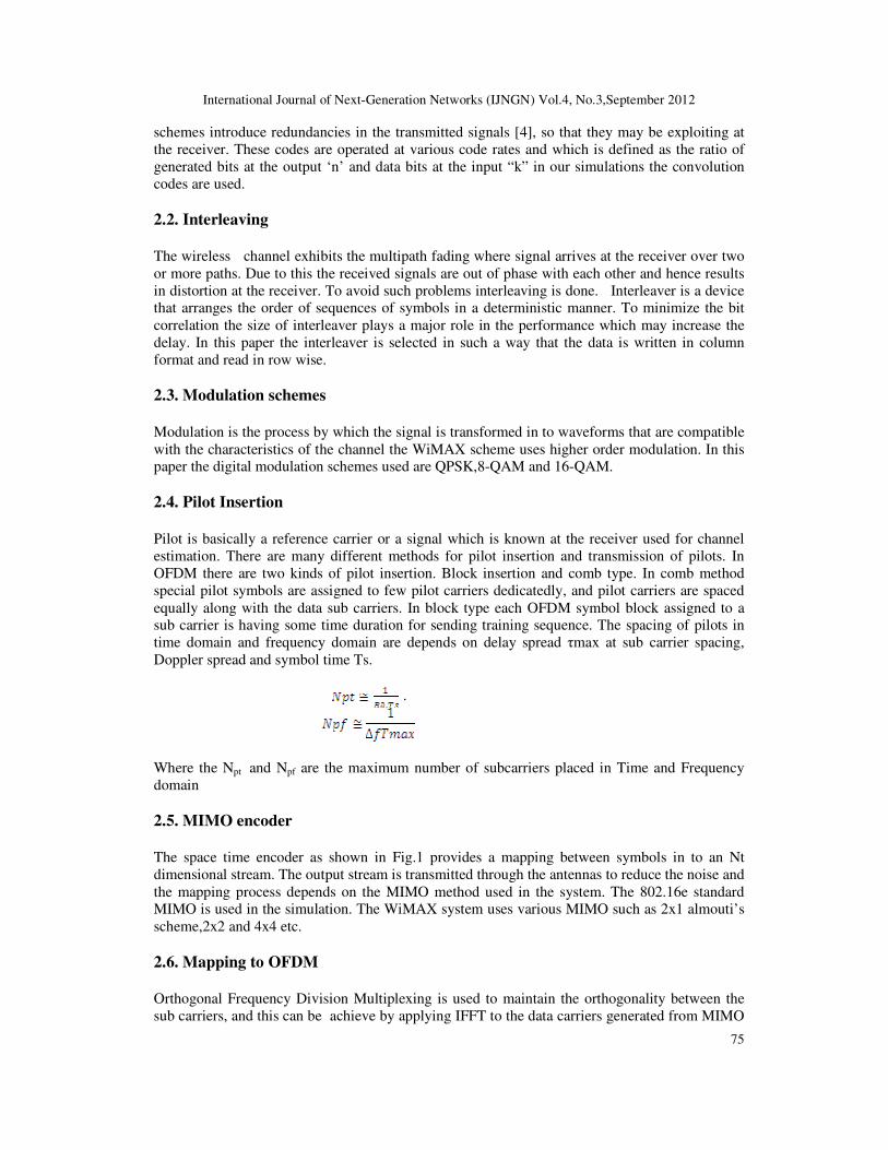
In the transmission of digital signals the FEC block of Fig.1. is a class of signal transformation
designed to improve the performance. It enables the transmitted signal to better with stand the
effects of various channel impairments such as noise, fading and interference. These coding
International Journal of Next-Generation Networks (IJNGN) Vol.4, No.3,September 2012
75
schemes introduce redundancies in the transmitted signals [4], so that they may be exploiting at
the receiver. These codes are operated at various code rates and which is defined as the ratio of
generated bits at the output ‘n’ and data bits at the input “k” in our simulations the convolution
codes are used.
2.2. Interleaving
The wireless channel exhibits the multipath fading where signal arrives at the receiver over two
or more paths. Due to this the received signals are out of phase with each other and hence results
in distortion at the receiver. To avoid such problems interleaving is done. Interleaver is a device
that arranges the order of sequences of symbols in a deterministic manner. To minimize the bit
correlation the size of interleaver plays a major role in the performance which may increase the
delay. In this paper the interleaver is selected in such a way that the data is written in column
format and read in row wise.
2.3. Modulation schemes
Modulation is the process by which the signal is transformed in to waveforms that are compatible
with the characteristics of the channel the WiMAX scheme uses higher order modulation. In this
paper the digital modulation schemes used are QPSK,8-QAM and 16-QAM.
2.4. Pilot Insertion
Pilot is basically a reference carrier or a signal which is known at the receiver used for channel
estimation. There are many different methods for pilot insertion and transmission of pilots. In
OFDM there are two kinds of pilot insertion. Block insertion and comb type. In comb method
special pilot symbols are assigned to few pilot carriers dedicatedly, and pilot carriers are spaced
equally along with the data sub carriers. In block type each OFDM symbol block assigned to a
sub carrier is having some time duration for sending training sequence. The spacing of pilots in
time domain and frequency domain are depends on delay spread τmax at sub carrier spacing,
Doppler spread and symbol time Ts.
.
Where the Npt and Npf are the maximum number of subcarriers placed in Time and Frequency
domain
2.5. MIMO encoder
The space time encoder as shown in Fig.1 provides a mapping between symbols in to an Nt
dimensional stream. The output stream is transmitted through the antennas to reduce the noise and
the mapping process depends on the MIMO method used in the system. The 802.16e standard
MIMO is used in the simulation. The WiMAX system uses various MIMO such as 2x1 almouti’s
scheme,2x2 and 4x4 etc.
2.6. Mapping to OFDM
Orthogonal Frequency Division Multiplexing is used to maintain the orthogonality between the
sub carriers, and this can be achieve by applying IFFT to the data carriers generated from MIMO
International Journal of Next-Generation Networks (IJNGN) Vol.4, No.3,September 2012
76
encoders. The OFDM sub carriers are basically in frequency domain hence by using IFFT the
orthogonality between the sub carriers and can be maintained. In this paper the size of FFT is
selected as per the standard of IEEE802.16e WiMAX group [2], as the more size of FFT increase
the resolution of the system.
Figure 1. Standard WiMAX system IEEE 802.16d
2.7. Cyclic prefix
Inter Symbol Interference is the major problem in high data rate communications. To avoid this a
guard period is inserted between the transmitted symbols. The most effective way of using guard
period is adding cyclic prefix to the symbol. Transmitting the cyclic prefix of data during guard
interval results in converting linearly convolution of channel into circular convolute channel with
transmitted signal. When a guard interval is longer than the channel impulse response or the multi
path delay then ISI is eliminated.
2.8. Channel models
The channel is communication medium between transmitter and the receiver. The wireless signal
changes its characteristics as it travels to certain distance from transmitter to receiver. These
characteristics depends on path taken by the signal, distance between the transmitter and receiver
and environment around the path. The symbol received at the receiver is results of convolution of
the transmitted symbol is multiplied with channel response and added with white noise.
International Journal of Next-Generation Networks (IJNGN) Vol.4, No.3,September 2012
77
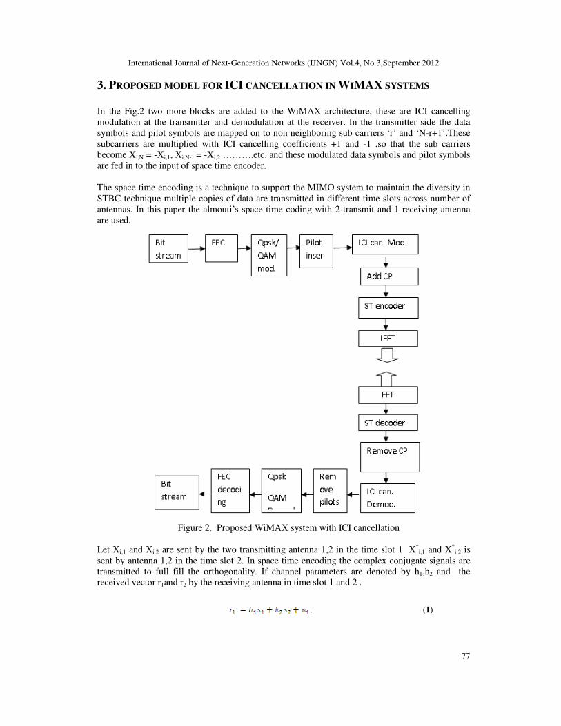
3. PROPOSED MODEL FOR ICI CANCELLATION IN WIMAX SYSTEMS
In the Fig.2 two more blocks are added to the WiMAX architecture, these are ICI cancelling
modulation at the transmitter and demodulation at the receiver. In the transmitter side the data
symbols and pilot symbols are mapped on to non neighboring sub carriers ‘r’ and ‘N-r+1’.These
subcarriers are multiplied with ICI cancelling coefficients +1 and -1 ,so that the sub carriers
become Xi,N = -Xi,1, Xi,N-1 = -Xi,2 ……….etc. and these modulated data symbols and pilot symbols
are fed in to the input of space time encoder.
The space time encoding is a technique to support the MIMO system to maintain the diversity in
STBC technique multiple copies of data are transmitted in different time slots across number of
antennas. In this paper the almouti’s space time coding with 2-transmit and 1 receiving antenna
are used.
Figure 2. Proposed WiMAX system with ICI cancellation
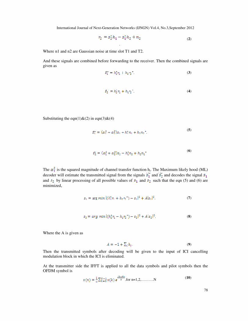
Let Xi,1 and Xi,2 are sent by the two transmitting antenna 1,2 in the time slot 1 X*i,1 and X*
i,2 is
sent by antenna 1,2 in the time slot 2. In space time encoding the complex conjugate signals are
transmitted to full fill the orthogonality. If channel parameters are denoted by h1,h2 and the
received vector r1and r2 by the receiving antenna in time slot 1 and 2 .
. (1)
International Journal of Next-Generation Networks (IJNGN) Vol.4, No.3,September 2012
78
.
(2)
Where n1 and n2 are Gaussian noise at time slot T1 and T2.
And these signals are combined before forwarding to the receiver. Then the combined signals are
given as
. (3)
. (4)
Substituting the eqn(1)&(2) in eqn(3)&(4)
. (5)
(6)
The is the squared magnitude of channel transfer function hi. The Maximum likely hood (ML)
decoder will estimate the transmitted signal from the signals and and decodes the signal
and by linear processing of all possible values of and such that the eqn (5) and (6) are
minimized,
. (7)
. (8)
Where the A is given as
. (9)
Then the transmitted symbols after decoding will be given to the input of ICI cancelling
modulation block in which the ICI is eliminated.
At the transmitter side the IFFT is applied to all the data symbols and pilot symbols then the
OFDM symbol is
.for n=1,2,……….N (10)
International Journal of Next-Generation Networks (IJNGN) Vol.4, No.3,September 2012
79
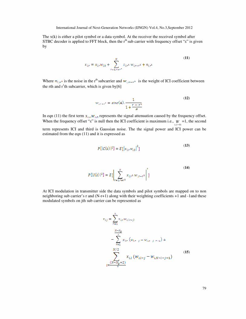
The x(k) is either a pilot symbol or a data symbol. At the receiver the received symbol after
STBC decoder is applied to FFT block, then the rth sub carrier with frequency offset “ε” is given
by
(11)
Where is the noise in the rth subcarrier and is the weight of ICI coefficient between
the rth and r1th subcarrier, which is given by[6]
(12)
In eqn (11) the first term represents the signal attenuation caused by the frequency offset.
When the frequency offset “ε” is null then the ICI coefficient is maximum i.e.,)0(, −ri
W =1, the second
term represents ICI and third is Gaussian noise. The the signal power and ICI power can be
estimated from the eqn (11) and it is expressed as
(13)
(14)
At ICI modulation in transmitter side the data symbols and pilot symbols are mapped on to non
neighboring sub carrier’s r and (N-r+1) along with their weighting coefficients +1 and -1and these
modulated symbols on jth sub carrier can be represented as
(15)
International Journal of Next-Generation Networks (IJNGN) Vol.4, No.3,September 2012
80
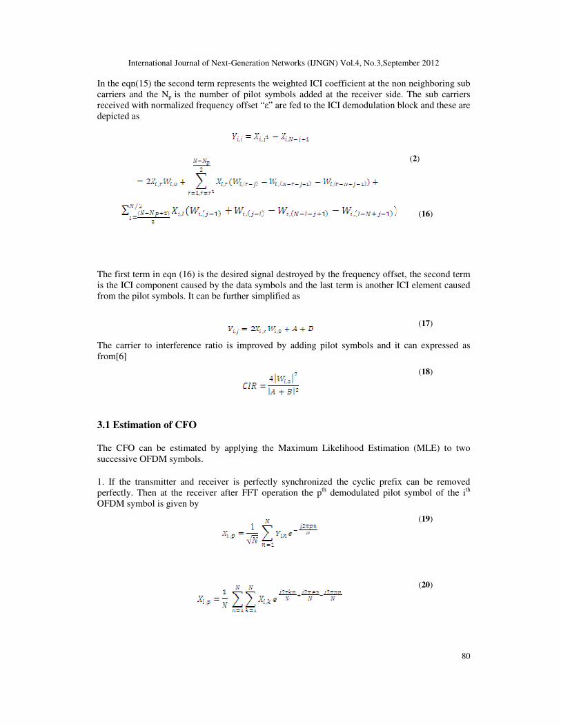
In the eqn(15) the second term represents the weighted ICI coefficient at the non neighboring sub
carriers and the Np is the number of pilot symbols added at the receiver side. The sub carriers
received with normalized frequency offset “ε” are fed to the ICI demodulation block and these are
depicted as
(2)
(16)
The first term in eqn (16) is the desired signal destroyed by the frequency offset, the second term
is the ICI component caused by the data symbols and the last term is another ICI element caused
from the pilot symbols. It can be further simplified as
(17)
The carrier to interference ratio is improved by adding pilot symbols and it can expressed as
from[6]
(18)
3.1 Estimation of CFO
The CFO can be estimated by applying the Maximum Likelihood Estimation (MLE) to two
successive OFDM symbols.
1. If the transmitter and receiver is perfectly synchronized the cyclic prefix can be removed
perfectly. Then at the receiver after FFT operation the pth demodulated pilot symbol of the ith
OFDM symbol is given by
(19)
(20)
International Journal of Next-Generation Networks (IJNGN) Vol.4, No.3,September 2012
81
Where Xi,p is a pilot symbol and Yi,n is the received ith OFDM symbol
2. In addition to the pth demodulated pilot symbol (i+1)th OFDM symbol is given by
(21)
It can be elaborated as
(22)
(23)
(24)
From the eqn(20) and(24) the partial CFO can be estimated as
(25)
More accurate partial CFO estimation can be obtained if more pilot symbols are inserted, In
addition to that the pilots symbols can be taken on for channel estimation. Besides the efficient
performance the pilot symbols decrease the band width utilization. However, the selection of the
size and the number of pilot symbols is based on the performance and band width utilization.
3.2 Channel models
The channel response depends upon key components like path loss, shadowing, multi path fading,
Doppler spread, Co channel and adjacent channel interference. The model parameters are varied
according to the atmospheric conditions and these depends upon terrain, tree density, antenna
height and beam width and also these parameters are random in nature and only statistical
averages are used to characterize them, i.e. in terms of the mean and variance value[8]. Based on
all above constraints SUI channels were proposed. There are a set of 6 channels representing 3
terrain types, variety of Doppler spreads, delay spreads and LOS/NLOS conditions.
International Journal of Next-Generation Networks (IJNGN) Vol.4, No.3,September 2012
82
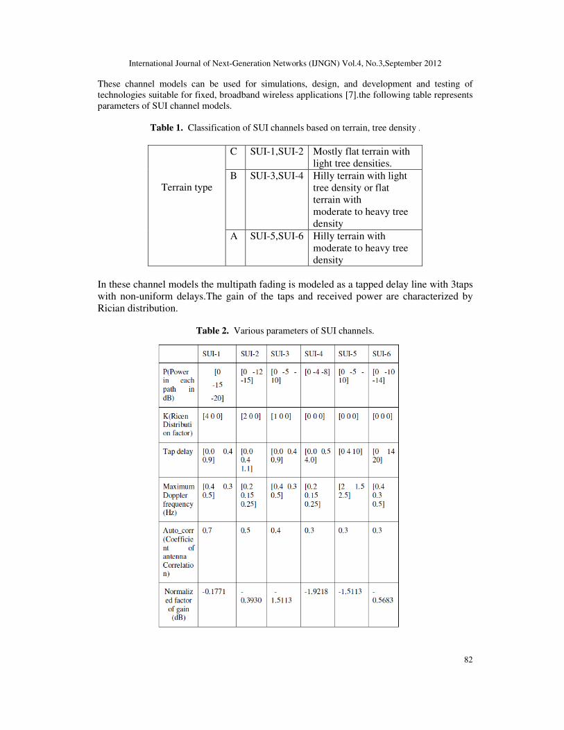
These channel models can be used for simulations, design, and development and testing of
technologies suitable for fixed, broadband wireless applications [7].the following table represents
parameters of SUI channel models.
Table 1. Classification of SUI channels based on terrain, tree density .
Terrain type
C SUI-1,SUI-2 Mostly flat terrain with
light tree densities.
B SUI-3,SUI-4 Hilly terrain with light
tree density or flat
terrain with
moderate to heavy tree
density
A SUI-5,SUI-6 Hilly terrain with
moderate to heavy tree
density
In these channel models the multipath fading is modeled as a tapped delay line with 3taps
with non-uniform delays.The gain of the taps and received power are characterized by
Rician distribution.
Table 2. Various parameters of SUI channels.
International Journal of Next-Generation Networks (IJNGN) Vol.4, No.3,September 2012
83
The probability density function of the received power ‘r’ is given as
(26)
I0(x) represents Bessel function. Here A is representing the LOS/NLOS component and is equal
to zero if no LOS component is present. Then the pdf becomes Rayleigh distribution and it is
given as
(27)
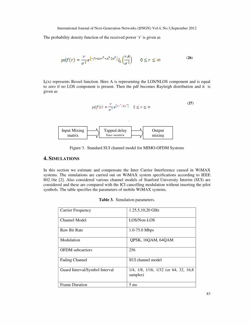
.
Figure 3. Standard SUI channel model for MIMO-OFDM Systems
4. SIMULATIONS
In this section we estimate and compensate the Inter Carrier Interference caused in WiMAX
systems. The simulations are carried out on WiMAX system specifications according to IEEE
802.16e [2]. Also considered various channel models of Stanford University Interim (SUI) are
considered and these are compared with the ICI cancelling modulation without inserting the pilot
symbols. The table specifies the parameters of mobile WiMAX systems.
Table 3. Simulation parameters.
Carrier Frequency
1.25,5,10,20 GHz
Channel Model
LOS/Non-LOS
Raw Bit Rate
1.0-75.0 Mbps
Modulation
QPSK, 16QAM, 64QAM
OFDM subcarriers
256
Fading Channel
SUI channel model
Guard Interval/Symbol Interval
1/4, 1/8, 1/16, 1/32 (or 64, 32, 16,8
samples)
Frame Duration 5 ms
Input Mixing
matrix
Tapped delay
line matrix
Output
mixing
International Journal of Next-Generation Networks (IJNGN) Vol.4, No.3,September 2012
84
Number of Frames (per second)
200
IFFT/FFT
512 point
No.of OFDM symbols in 5ms frame
48
No. of data sub carriers
192
No. of pilot sub carriers
60
Decoder
Viterbi
Noise
AWGN
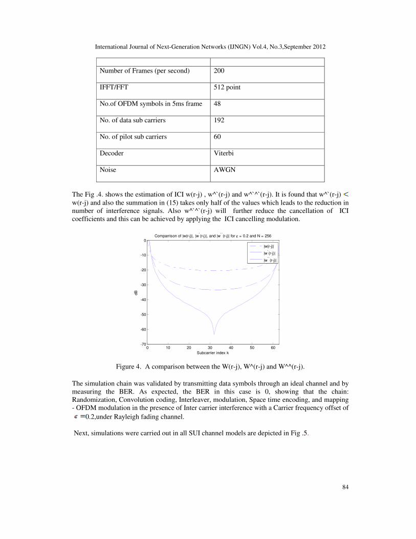
The Fig .4. shows the estimation of ICI w(r-j) , w^`(r-j) and w^`^`(r-j). It is found that w^`(r-j)
w(r-j) and also the summation in (15) takes only half of the values which leads to the reduction in
number of interference signals. Also w^`^`(r-j) will further reduce the cancellation of ICI
coefficients and this can be achieved by applying the ICI cancelling modulation.
0 10 20 30 40 50 60-70
-60
-50
-40
-30
-20
-10
0
Subcarrier index k
dB
Comparrison of |w(r-j)|, |w`(r-j)|, and |w``(r-j)| for ε = 0.2 and N = 256
|w(r-j)|
|w`(r-j)|
|w``(r-j)|
Figure 4. A comparison between the W(r-j), W^(r-j) and W^^(r-j).
The simulation chain was validated by transmitting data symbols through an ideal channel and by
measuring the BER. As expected, the BER in this case is 0, showing that the chain:
Randomization, Convolution coding, Interleaver, modulation, Space time encoding, and mapping
- OFDM modulation in the presence of Inter carrier interference with a Carrier frequency offset of
0.2,under Rayleigh fading channel.
Next, simulations were carried out in all SUI channel models are depicted in Fig .5.
International Journal of Next-Generation Networks (IJNGN) Vol.4, No.3,September 2012
85
0 2 4 6 8 10 12 14 16 18 2010
-3
10-2
10-1
100
BER of the pilot aided. ( G=0.125,BW=5MHz and modulation of 16QAM )
SUI-1
SUI-2
SUI-3
SUI-4
SUI-5
SUI-6
rayleigh
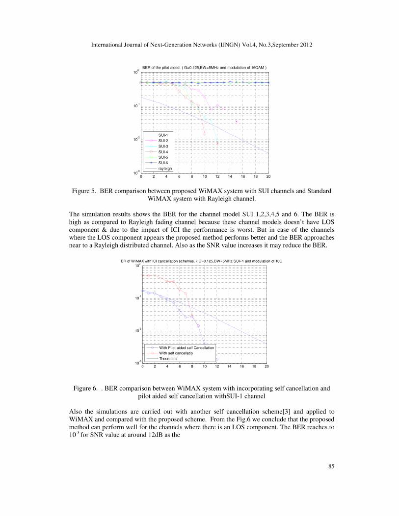
Figure 5. BER comparison between proposed WiMAX system with SUI channels and Standard
WiMAX system with Rayleigh channel.
The simulation results shows the BER for the channel model SUI 1,2,3,4,5 and 6. The BER is
high as compared to Rayleigh fading channel because these channel models doesn’t have LOS
component & due to the impact of ICI the performance is worst. But in case of the channels
where the LOS component appears the proposed method performs better and the BER approaches
near to a Rayleigh distributed channel. Also as the SNR value increases it may reduce the BER.
0 2 4 6 8 10 12 14 16 18 2010
-3
10-2
10-1
100
BER of WiMAX with ICI cancellation schemes. ( G=0.125,BW=5MHz,SUI=1 and modulation of 16QAM )
With Pilot aided self Cancellation
With self cancellatio
Theoretical
Figure 6. . BER comparison between WiMAX system with incorporating self cancellation and
pilot aided self cancellation withSUI-1 channel
Also the simulations are carried out with another self cancellation scheme[3] and applied to
WiMAX and compared with the proposed scheme. From the Fig.6 we conclude that the proposed
method can perform well for the channels where there is an LOS component. The BER reaches to
10-3 for SNR value at around 12dB as the
International Journal of Next-Generation Networks (IJNGN) Vol.4, No.3,September 2012
86
0 2 4 6 8 10 12 14 16 18 2010
-3
10-2
10-1
100
BER of WiMAX with ICI cancellation schemes. ( G=0.125,BW=5MHz,SUI=6 and modulation of 16QAM )
With Pilot aided self Cancellation
With self cancellatio
Theoretical
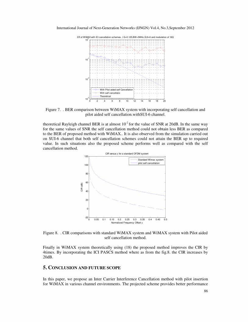
Figure 7. . BER comparison between WiMAX system with incorporating self cancellation and
pilot aided self cancellation.withSUI-6 channel.
theoretical Rayleigh channel BER is at almost 10-2
for the value of SNR at 20dB. In the same way
for the same values of SNR the self cancellation method could not obtain less BER as compared
to the BER of proposed method with WiMAX.. It is also observed from the simulation carried out
on SUI-6 channel that both self cancellation schemes could not attain the BER up to required
value. In such situations also the proposed scheme performs well as compared with the self
cancellation method.
0 0.05 0.1 0.15 0.2 0.25 0.3 0.35 0.4 0.45 0.5-20
0
20
40
60
80
100
120
Normalized Frequency Offset ε
CIR
(dB
)
CIR versus ε for a standard OFDM system
Standard Wimax system
pilot self cancellation
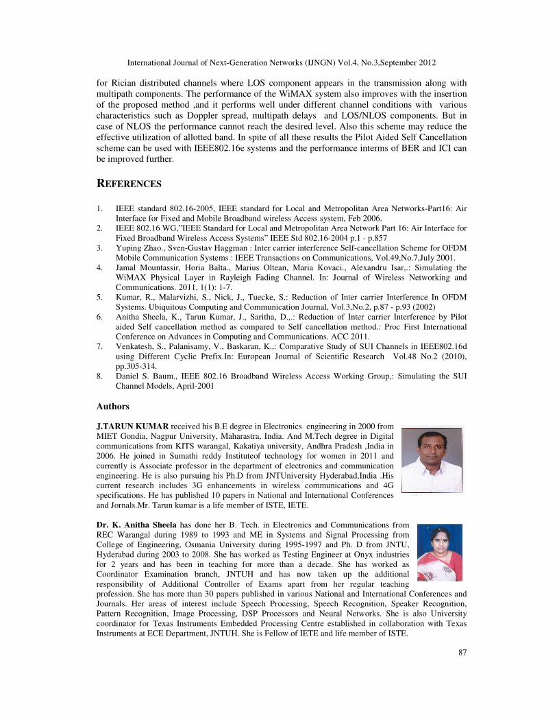
Figure 8. . CIR comparisons with standard WiMAX system and WiMAX system with Pilot aided
self cancellation method.
Finally in WiMAX system theoretically using (18) the proposed method improves the CIR by
4times. By incorporating the ICI PASCS method where as from the fig.8. the CIR increases by
20dB.
5. CONCLUSION AND FUTURE SCOPE
In this paper, we propose an Inter Carrier Interference Cancellation method with pilot insertion
for WiMAX in various channel environments. The projected scheme provides better performance
International Journal of Next-Generation Networks (IJNGN) Vol.4, No.3,September 2012
87
for Rician distributed channels where LOS component appears in the transmission along with
multipath components. The performance of the WiMAX system also improves with the insertion
of the proposed method ,and it performs well under different channel conditions with various
characteristics such as Doppler spread, multipath delays and LOS/NLOS components. But in
case of NLOS the performance cannot reach the desired level. Also this scheme may reduce the
effective utilization of allotted band. In spite of all these results the Pilot Aided Self Cancellation
scheme can be used with IEEE802.16e systems and the performance interms of BER and ICI can
be improved further.
REFERENCES
1. IEEE standard 802.16-2005, IEEE standard for Local and Metropolitan Area Networks-Part16: Air
Interface for Fixed and Mobile Broadband wireless Access system, Feb 2006.
2. IEEE 802.16 WG,”IEEE Standard for Local and Metropolitan Area Network Part 16: Air Interface for
Fixed Broadband Wireless Access Systems” IEEE Std 802.16-2004 p.1 - p.857
3. Yuping Zhao., Sven-Gustav Haggman : Inter carrier interference Self-cancellation Scheme for OFDM
Mobile Communication Systems : IEEE Transactions on Communications, Vol.49,No.7,July 2001.
4. Jamal Mountassir, Horia Balta., Marius Oltean, Maria Kovaci., Alexandru Isar,.: Simulating the
WiMAX Physical Layer in Rayleigh Fading Channel. In: Journal of Wireless Networking and
Communications. 2011, 1(1): 1-7.
5. Kumar, R., Malarvizhi, S., Nick, J., Tuecke, S.: Reduction of Inter carrier Interference In OFDM
Systems. Ubiquitous Computing and Communication Journal, Vol.3,No.2, p.87 - p.93 (2002)
6. Anitha Sheela, K., Tarun Kumar, J., Saritha, D.,.: Reduction of Inter carrier Interference by Pilot
aided Self cancellation method as compared to Self cancellation method.: Proc First International
Conference on Advances in Computing and Communications. ACC 2011.
7. Venkatesh, S., Palanisamy, V., Baskaran, K.,: Comparative Study of SUI Channels in IEEE802.16d
using Different Cyclic Prefix.In: European Journal of Scientific Research Vol.48 No.2 (2010),
pp.305-314.
8. Daniel S. Baum., IEEE 802.16 Broadband Wireless Access Working Group,: Simulating the SUI
Channel Models, April-2001
Authors J.TARUN KUMAR received his B.E degree in Electronics engineering in 2000 from
MIET Gondia, Nagpur University, Maharastra, India. And M.Tech degree in Digital
communications from KITS warangal, Kakatiya university, Andhra Pradesh ,India in
2006. He joined in Sumathi reddy Instituteof technology for women in 2011 and
currently is Associate professor in the department of electronics and communication
engineering. He is also pursuing his Ph.D from JNTUniversity Hyderabad,India .His
current research includes 3G enhancements in wireless communications and 4G
specifications. He has published 10 papers in National and International Conferences
and Jornals.Mr. Tarun kumar is a life member of ISTE, IETE.
Dr. K. Anitha Sheela has done her B. Tech. in Electronics and Communications from
REC Warangal during 1989 to 1993 and ME in Systems and Signal Processing from
College of Engineering, Osmania University during 1995-1997 and Ph. D from JNTU,
Hyderabad during 2003 to 2008. She has worked as Testing Engineer at Onyx industries
for 2 years and has been in teaching for more than a decade. She has worked as
Coordinator Examination branch, JNTUH and has now taken up the additional
responsibility of Additional Controller of Exams apart from her regular teaching
profession. She has more than 30 papers published in various National and International Conferences and
Journals. Her areas of interest include Speech Processing, Speech Recognition, Speaker Recognition,
Pattern Recognition, Image Processing, DSP Processors and Neural Networks. She is also University
coordinator for Texas Instruments Embedded Processing Centre established in collaboration with Texas
Instruments at ECE Department, JNTUH. She is Fellow of IETE and life member of ISTE.