establishing dense correspondence of high resolution · pdf fileestablishing dense...
TRANSCRIPT

Establishing Dense Correspondence of High Resolution 3D Faces via Möbius Transformations
Jian Liu1, Quan Zhang1, Chaojing Tang1*
1 College of Electronic Science and Engineering, National University of Defense Technology, Changsha, China. * Corresponding author. Email: [email protected] Manuscript submitted July 14, 2014; accepted November 2, 2014.
Abstract: The aim of the paper is to establish dense correspondence of high resolution 3D human faces. To
achieve the goal, this paper proposes an automatic method to establish dense correspondence of high
resolution 3D human faces via Möbius Transformations. For high resolution 3D faces, geodesic remeshing is
used to reduce the number of vertices. Since the extent of the 3D face data varies from example to example,
an ellipse fit method is proposed to extract consistently matching face points. The facial feature points are
located by using texture and shape information of 3D faces. These correspondent facial feature points are
used to generate Möbius transformations and achieve sparse correspondence between 3D faces. TPS
(Thin-Plate Spline) transformation is used to represent the deformation of 3D faces by using controlling
points which selected from the sparse correspondence set. For every vertex of the TPS warped reference 3D
face, they are projected into every triangle face of the sample 3D face, then the closest projections are used
to define the new mesh vertices of the sample 3D face. The sample 3D face with new mesh shares the same
connectivity with the reference 3D face, thus the dense correspondence between the reference 3D face and
the sample 3D face with new mesh is achieved. The experimental results on BJUT-3D face database show
that our method achieves better performance than existing methods.
Key words: Correspondence, ellipse fit, Möbius transformation, thin-plate spline.
1. Introduction
Establishing dense correspondence between high resolution 3D human faces is a very important and
complex problem. Solving the problem can contribute to facial modeling [1], shape registration [2], face
transfer [3], face recognition [4], shape matching [5], etc. For example, [1] proposed a morphable face
model which can be used in facial modeling and facial animation. When building the morphable face model,
the shape and texture of the 3D face examples must be transformed into a vector space representation. So
different 3D faces must be registered by computing dense one-to-one correspondence between these 3D
faces. Furthermore, through the dense one-to-one correspondence, if each 3D face can be represented as a
vector by concatenating the coordinates and texture information of its vertices, the vectors can be viewed as
an effective features for face modeling and recognition, and we can apply many mathematical tools such as
Principal Component Analysis (PCA) directly to these concatenated vectors [6].
Establishing dense correspondence between high resolution 3D human faces is a challenging work. One
reason is that the geometry of the 3D face is very complex, the extent of the 3D face data varies from
example to example [7]. The number of the clearly correspondent points between different 3D faces is very
International Journal of Computer and Electrical Engineering
479 Volume 6, Number 6, December 2014
doi: 10. 17706/ijcee.2014.v6.866

small, these points are mostly the distinct feature points in human face, such as the nose tip, the corner of
eyes and lip, etc. [8] For the points on the smooth regions of human face (cheek, forehead, etc.), it's difficult
to define the correspondence [9]. Another reason is that with the development of the 3D data acquisition
technology and computer visualization technology, it is convenient to acquire high resolution 3D faces [10].
For high resolution 3D human faces, the vertices numbers are usually beyond 50000, some even beyond
70000, it's time consuming to process such high resolution 3D faces.
1.1. Related Work
Existing methods which related to our work can be commonly classified into ICP (Iterative Closest Point)
based and TPS (Thin-Plate Spline) based types.
The ICP algorithm proposed by [11] starts with an initial rigid transformation and iteratively searches for
closest points in two surfaces and optimizes the rigid transformation by minimizing the mean square
distance metric. There are also many variants of the ICP method, such as [12], [13], [14], etc. These ICP
methods are based on the rigid transformation, which are unsuitable for non-rigid deformation, such as
with 3D human faces. For the non-rigid deformation, [15] proposed a hierarchical method for aligning
warped meshes, they used a piecewise rigid compensating warp and cut each mesh into a set of overlapping
regions, these overlapping regions were allowed to translate and rotate relative to each other. The resulting
set of regions and their translations and rotations constituted a piecewise rigid approximation of the curved
warp. The method of [15] can obtain global alignment with non-rigid deformation, but their method
pertains to the choice of compensating warp, and the local rigid transformation was not suitable for
complex shape variety such as high resolution 3D human faces.
When dealing with 3D human face, thin-plate spline (TPS) is used for transferring the landmark-based
deformation since it is the only spline that can be cleanly decomposed into affine and non-affine subspaces
while minimizing a global bending energy function [16] based on the second derivative of the spatial
mapping. In this sense, the TPS can be considered to be a natural non-rigid extension of the affine map. As a
result, for non-rigid deformation of 3D human faces, The TPS transformation has been widely used. [17]
proposed a point matching algorithm named TPS-RPM (Thin-Plate Spline-Robust Point Matching)
algorithm for non-rigid registration. They formulate feature-based non-rigid registration as a non-rigid
point matching problem. The TPS-RPM algorithm utilizes the softassign, deterministic annealing [18], [19],
[20], the thin-plate spline for the spatial mapping and outlier rejection to compute point correspondence
iteratively. Although the performance of the TPS-RPM algorithm is demonstrated and validated in a series of
carefully designed synthetic experiments, when dealing with 3D faces, it will perform not so well because of
the dimension limitation of the correspondence matrix and the impracticalness of applying TPS on global
dense point sets. [9] presented an automatic point matching method which adopted the TPS transformation
to model the deformation of 3D faces. They proposed a random point selecting method to get the
controlling points for TPS transformation and used an iterative closest point searching strategy to achieve
dense point alignment of 3D faces. The main disadvantage of this method was that the deformations of
some local shapes are not satisfactory because some of the controlling points were improperly selected. [10]
proposed an automatic multi-sample 3D face registration method. Different from [9], they generated the
controlling points of TPS by using a farthest point sampling (FPS) method and used a dynamical reference
based on deformable model to implement the multi-sample registration. Since the controlling points
generated by FPS method cannot guarantee sparse correspondence, the result of dense correspondence are
not so well. [8] described a non-rigid registration method for fully automatic 3D facial image mapping. They
first used shape and texture information to locate the facial feature points, then used these facial feature
points as controlling points for TPS transformation. When building the dense correspondence, they
designed a scheme to define the new mesh vertices of the sample surface, and after all the sample surfaces
International Journal of Computer and Electrical Engineering
480 Volume 6, Number 6, December 2014

were remeshed using the same reference, the dense correspondence was established.
1.2. Outline of Our Work
This paper proposes an automatic method to establish dense correspondence of high resolution 3D
human faces via Möbius Transformations. Our method are mainly inspired by [8] and [21]. In our method,
we first use geodesic remeshing to reduce the vertices number of the 3D faces (Section 2), which can
alleviate the time consuming problem when processing the high resolution 3D faces, then we propose an
ellipse fit method to extract consistently matching face points since the extent of the 3D face data varies
from example to example (Section 3). After extracting the consistently matching face points, we use the
texture and shape information of the 3D faces to locate facial feature points (Section 4.1), the main
contribution of these facial feature points is to generate Möbius transformations [21]. When we get these
Möbius transformations, we can utilize them to generate sparse correspondent points (Section 4.2). Finally,
we perform TPS warping to achieve dense correspondence by using the sparse correspondent points as
control points (Section 5). During TPS warping, we defined a new mesh of the sample 3D face by using the
closest projections (Section 5), when finding the closest projections, we propose a new method to project a
vertex to a triangle (Section 5).
2. Geodesic Remeshing
For high resolution 3D human faces, the vertices numbers are usually beyond 50000, some even beyond
70000. It's time consuming to process such high resolution 3D faces. To alleviate the time-consuming
procedures, one obvious solution is to reduce the vertices number of the 3D faces and maintain the
resolution as high as possible. Since different 3D faces always have different number of vertices, we also
should make them have the same number of vertices. To achieve these goals, we use the method proposed
by [22], because their method is fast and easy to implement. Our intuitive idea is: (1) Select one 3D face
from 3D face databases as reference 3D face; (2) Geodesic remesh the reference 3D face with some proper
vertices number which is smaller than the original vertices number of the reference 3D face; (3) Using the
remeshed reference 3D face to sample other 3D faces, thus all the 3D faces have the same vertices number
and share the same connectivity, that is, they are in full dense correspondence.
We choose the nose tip as the start point. Because at this stage we don't demand high accuracy of the
nose tip's position, we simply transform the 3D face's three-dimensional Cartesian coordinates ( , ,x y z )
into cylindrical coordinates ( , ,z ), and choose the vertex whose radial distance have maximum
value as the nose tip. That is:
2 2 , 1,...,i i ix y i N
1max , 1,...,nose tip j i
i NID j j N
where i is the radial distance of the ith 3D face's vertex, ( , ,i i ix y z ) is the Cartesian coordinate of the ith
3D face's vertex, N is the total vertices number of the 3D face, nose tipID is the nose tip's vertex ID.
After choosing the nose tip as the start point, we iteratively add most geodesically distant point from the
points we already have added on the 3D face's surface. Then we use the method in [22] to calculate the
geodesic triangles. Fig. 1 shows the remeshing result, the original 3D face's vertices number is about 70000,
the remeshed 3D face's vertices number is 30000.
International Journal of Computer and Electrical Engineering
481 Volume 6, Number 6, December 2014

(a) (b)
(a) (b)
Fig. 1. (a) Original 3D face; (b) Remeshed 3D face.
3. Compute Consistently Matching Face Points
For different 3D faces, the boundaries of them are poorly defined, the extent of the 3D face data varies
from example to example [7]. For example, the 3D face scans in the 3D face database often include
significant neck and ear areas that are not present in all the examples [7]. So, finding dense correspondence
between different 3D faces is a partial correspondence problem [23]. To effectively establish dense
correspondence between 3D faces, we should search for an optimal subset of k face points that match
consistently, then find the dense correspondence between these k elements [23].
We observe that the ellipsoidal area around the five sense organs of 3D face is the consistently matched
area between different 3D faces. So we should find ways to search the optimal subset of k face points
within the ellipsoidal area. Here we propose an ellipse fit method to extract the optimal subset of k face
points. The method is as follows:
1) Get 2D face image. Since the 3D face have texture information in each vertex, we simply transform the
Cartesian coordinates of the 3D faces to cylindrical coordinates.
2 2 1, tan ( / ),x y y x z z
Fig. 2 shows the transform result.
(a) (b) (c) Fig. 2. Transform the Cartesian coordinates of (a) original 3D face to cylindrical coordinates, use the
cylindrical coordinates and texture information to get (b) 2D face texture image and (c) 2D face shape
image.
2) Ellipse fit. We use the method proposed by [24] to locate facial profile feature points in 2D face image.
Fig. 3 shows the result of locating facial profile feature points.
Fig. 3. The result of locating facial profile feature points.
International Journal of Computer and Electrical Engineering
482 Volume 6, Number 6, December 2014
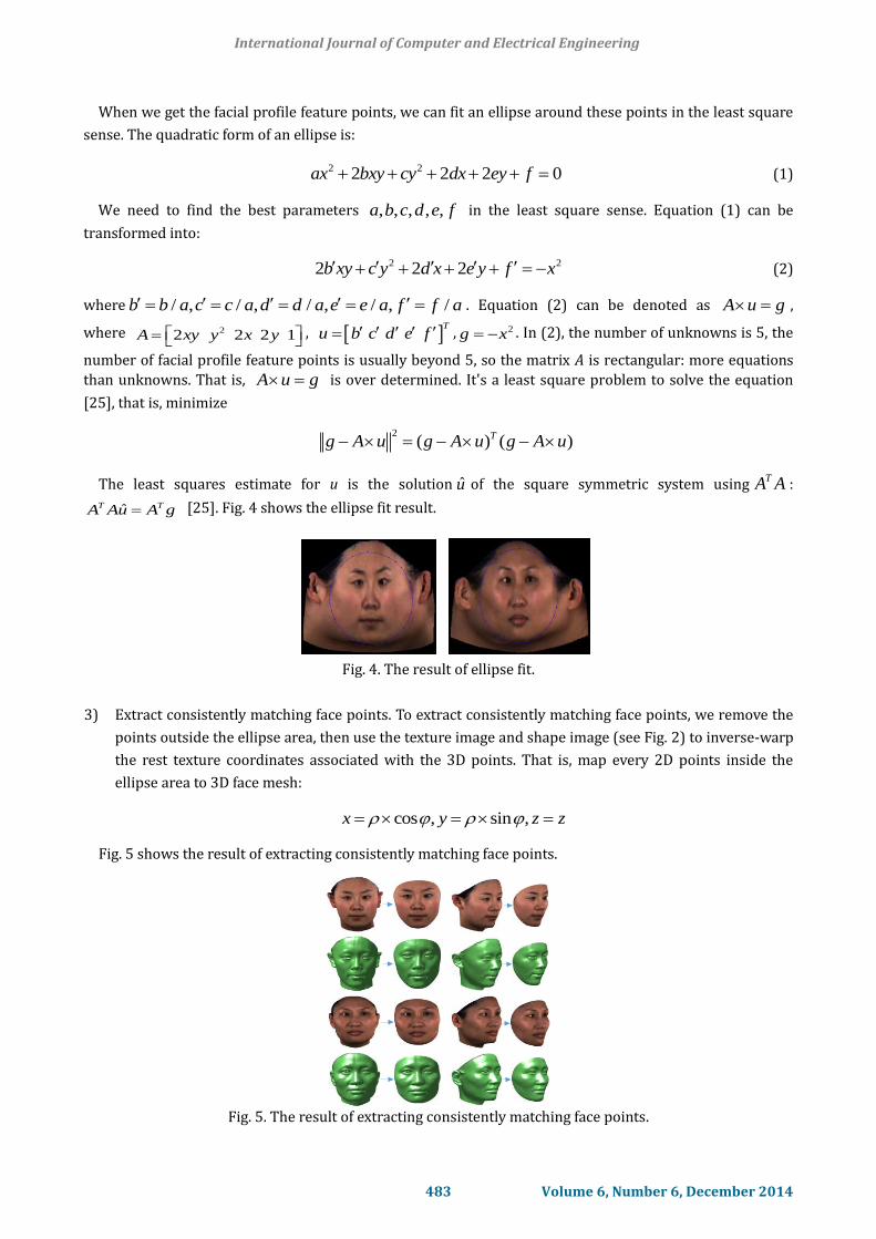
When we get the facial profile feature points, we can fit an ellipse around these points in the least square
sense. The quadratic form of an ellipse is:
2 22 2 2 0ax bxy cy dx ey f (1)
We need to find the best parameters , , , , ,a b c d e f in the least square sense. Equation (1) can be
transformed into:
2 22 2 2b xy c y d x e y f x (2)
where / , / , / , / , /b b a c c a d d a e e a f f a . Equation (2) can be denoted as A u g ,
where 22 2 2 1A xy y x y ,
Tu b c d e f , 2g x . In (2), the number of unknowns is 5, the
number of facial profile feature points is usually beyond 5, so the matrix A is rectangular: more equations
than unknowns. That is, A u g is over determined. It's a least square problem to solve the equation
[25], that is, minimize
2( ) ( )Tg A u g A u g A u
The least squares estimate for u is the solution u of the square symmetric system usingTA A :
ˆT TA Au A g [25]. Fig. 4 shows the ellipse fit result.
Fig. 4. The result of ellipse fit.
3) Extract consistently matching face points. To extract consistently matching face points, we remove the
points outside the ellipse area, then use the texture image and shape image (see Fig. 2) to inverse-warp
the rest texture coordinates associated with the 3D points. That is, map every 2D points inside the
ellipse area to 3D face mesh:
cos , sin ,x y z z
Fig. 5 shows the result of extracting consistently matching face points.
Fig. 5. The result of extracting consistently matching face points.
International Journal of Computer and Electrical Engineering
483 Volume 6, Number 6, December 2014

4. Sparse Correspondence
In order to find dense correspondence between 3D faces, we should find sparse correspondence between
3D faces at first. Since we will perform TPS (Thin-Plate Spline) warp on the 3D faces to achieve dense
correspondence, it is vital to select proper and enough control points for TPS [10]. Fig. 6 shows the main
steps to achieve sparse correspondence between 3D faces.
(a) (b)
Fig. 6. The main steps to achieve sparse correspondence between 3D faces. (a) Locate facial feature points.
(b) Möbius voting based on facial feature points.
4.1. Locate Facial Feature Points
Since every vertex in the 3D faces have texture information, we can use such texture information to locate
the facial feature points. When we locate the facial feature points based on texture information, we can
further extract the more correspondent facial feature points with the help of 3D shape information.
The main techniques here we used are a unified tree-structured model [24] and shape index [26]. We use
the method proposed by [24] to locate facial feature points in 2D images since their method is very effective
and especially useful when dealing with image in wild. We should point out that in our sparse
correspondence procedure, we can use other techniques to locate the facial feature points in 2D images (e.g.
[8] and [27]), as long as such techniques can achieve accurate result when locating facial feature points.
We first transform the Cartesian coordinates of the 3D faces to cylindrical coordinates (Fig. 2), then use
the method proposed by [24] to locate the facial feature points. The detail to find the facial feature points
can be found in [24]. After locating the facial feature points in 2D images, we can use the 2D face texture
image and shape image (Fig. 2) to map every 2D facial feature points to 3D face mesh. Fig. 7 shows the
result of locating the facial feature points.
(a) (b) Fig. 7. The result of locating the facial feature points. (a) Facial feature points in 2D image. (b) Facial feature
points in 3D image.
There may exist noise in the 3D face texture information, and when transform the Cartesian coordinates
to the cylindrical coordinates, some 3D geometric information may lose, so there will be some errors when
locate the 3D facial feature points. To achieve sparse correspondence, we must get rid of those errors. We
International Journal of Computer and Electrical Engineering
484 Volume 6, Number 6, December 2014

can use 3D information of the 3D face to get rid of those errors and further extract correspondent facial
feature points pairs. The shape index [26] captures the intuitive notion of local shape such as convex, saddle,
and concave of a surface, and can describe subtle shape variations. Considering the complexity of human
face, we use the difference of the shape index of the points to determine if these points are really
correspondent. The equation of the shape index difference between point p and q is
( , ) ( ) ( )I ID p q S p S q
1 1 2
1 2
( ) ( )1 1( ) tan
2 ( ) ( )I
p pS p
p p
where ( )IS p is the shape index of point p, 1 and
2 are the principal curvatures of the surface with
1 2 . If ( , )D p q is beyond some threshold, then point p and q are not correspondent, we get rid of
them from the correspondent facial feature points pairs.
4.2. Möbius Voting Based on Facial Feature Points
Since the 3D human faces are near-isometric genus-zero surfaces, we can use Möbius voting to get the
sparse correspondence set. [21] found a way to search for isometries or near-isometries between two
different genus-zero surfaces M, N in the space of Möbius transformations. The main technique we used is
motivated by it.
The steps of the technique is as follows:
1) Uniformization.
We use the mid-edge uniformization step of [21] to map the 3D face mesh surface to the extended
complex plane ℂ. We map each vertex iv V to 𝑧𝑖 ∈ ℂ by denoting iv as the mid-edge point rv which
is geodesically closest to iv . Because each rv corresponds to each iz , thus the 3D face mesh M is
flattened. Fig. 8 shows the uniformization result.
Fig. 8. Uniformization result.
2) Point sample.
We select every correspondent point from the correspondent facial feature point’s pairs as the start
points, then uniformly sample discrete sets of N points 1S and 2S from each 3D face M and N, as
described by [21]. Then project 1S and 2S onto the complex plane ℂ to form the planar point samples
1 2,t tS p S q .
3) Generating Möbius transformations.
International Journal of Computer and Electrical Engineering
485 Volume 6, Number 6, December 2014

Different from [21], we use the 3D facial feature points pairs ( , )r sp q to generate the Möbius
transformations. We map ( , )r sp q to the extended complex plane ℂ : ( , )r sz w firstly. Then
exhaustedly search the triplets of points from ( , )r sz w : 1 2 3, ,r r r rz z z z , 1 2 3, ,s s s sw w w w , and
find the Möbius transformations1 2,m m subject to
1( )rj jm z y , 2 ( )sj jm w y , 1,2,3j where m denotes
the Möbius transformation m z az b cz d , , 1,2,3jy j denotes a canonical domain in the
extended complex plane. Here we set exp( 2 / 3), 1,2,3jy i j j , which means thatjy forms a scale and
position do not matter equilateral. After we find the Möbius transformations1 2,m m , we can apply
1m on
1S to get 1( )r tz m p , apply
2m on 2S to get
2( )s tw m q .
4) Cast vote.
We maintain a non-negative real matrix ,1( )kCC with dimensions 1 2S S . For every Möbius
transformation generated by step 3, we find mutually nearest-neighbors ,r sz w in the flattened space. If
the number of mutually closest pairs is not less than a threshold K, we compute
1 2, ,r s t tz w S p S q
As the vote value and sum it into the fuzzy correspondence matrix:
, , 1 2, ,r s r s r s t tC C z w S p S q
where ,r sz w is the number of mutually closest pairs, 1 2,t tS p S q is the number of the
points pairs 1 2,t tS p S q .
5) Extract correspond pairs.
We use the max-row-column algorithm [21] to iteratively look for the maximal entry greater than zero in
the fuzzy correspondence matrix ,( )r sCC and get the correspondence map ( , )u vp q .
5. Dense Correspondence
Now we have the sparse correspondence set, which includes 3D facial feature points pairs and Möbius
voting correspondent pairs, next we will use the sparse correspondence set to achieve dense
correspondence. Here we use the TPS-based method. For simplicity, we call the remeshed 3D face as
reference face M, one of the other 3D faces as sample face N. We use the point pairs in the sparse
correspondence set as fiducial points and TPS warp the reference face M to the sample face N as described
by [28]. After warping, the sample face N and the warped reference face M’ are topologically similar. Then
for every vertex of the warped reference face M’, we project them to every triangle face of the sample face N
and find the closest ones, then we use the closest projections to define the new mesh vertices of the sample
face. We denote the sample face with the new mesh vertices as N’ , we can see that the vertices number and
order of N’ is the same as the vertices number and order of M, and N’ shares the same connectivity with the
reference face M, thus the dense correspondence between M and N’ is achieved.
When finding the closest projections, we proposed a new method to project a vertex to a triangle. Fig. 9
shows a triangle in 3D space.
International Journal of Computer and Electrical Engineering
486 Volume 6, Number 6, December 2014

Line 1 Line 2
Line 3
Line 4Line 5
Line 6 a
c
b
Region 1
Region 2
Region 3
Region 4
Region 5
Region 6
Region 7
Fig. 9. Triangle in 3D space.
In Fig. 9, we divide the plane of the triangle into 7 regions, where line 1 and line 2 are orthogonal to line
ab, line 3 and line 4 are orthogonal to line bc, line 5 and line 6 are orthogonal to line ca. For vertex v in the
3D space, we first project it to the plane of the triangle and get the point v'. If v' belongs to region 7, then it is
the projection result; If v' belongs to region 2, or region 4, or region 6, the projection result is just the
triangle's vertex b, or vertex c, or vertex a respectively; if v' belongs to region 1, or region 3, or region 5, we
simply project v' to line ab, or line bc, or line ca respectively to get the projection point v'', v'' is the
projection result. Fig. 10 shows one example of the projection.
Line 1 Line 2
Line 3
Line 4Line 5
Line 6 a
c
b
Region 1
Region 2
Region 3
Region 4
Region 5
Region 6
Region 7
v
V’
V’’
Fig. 10. One example of closest projection.
In Fig. 10, v is projected to the plane of the triangle and get point v', which is in region 3, so we project v'
to line bc and get point v'', which is the projection result.
When we get the projection result v'', we can use barycentric coordinates to get the texture information of
v''. That is as follows, we first get the barycentric coordinates 1 2 3, , of point v'' in triangle abc, then
the texture information of v'' can be calculated as 1 2 3a b cT T T T , where , ,a b cT T T are
texture information of vertex a, vertex b and vertex c respectively.
6. Experiments and Results
The experiments are implemented on BJUT-3D face database [29]. This database contains 500 Chinese
3D faces (250 females and 250 males) which are acquired by the CyberWare Laser Scanner in special
environment. Each subject has the 3D shape data and texture data and generally have more than 70000
vertices and 140000 triangles. There are 100 faces from BJUT-3D face database used in our experiments. To
evaluate the efficiency of geodesic remeshing, we measure the mean-square Hausdorff distance between
the original mesh and a series of geodesic remeshing versions. The Hausdorff distance between two sets of
points X and Y is
International Journal of Computer and Electrical Engineering
487 Volume 6, Number 6, December 2014

0 0, , ,d X Y d X Y d Y X
22
0
1, min
y Yx X
d X Y x yX
Table 1 shows the Hausdorff approximation errors with different sample numbers.
Table 1. Hausdorff Approximation Error
Sample
number 100 500 1000 3000 5000
700
0
Hausdor
ff error 10.52 4.68 3.28 1.86 1.43 1.20
Sample
number 10000 15000 20000 25000 30000
Hausdor
ff error 1.02 0.83 0.68 0.58 0.51
Fig. 11 (a) display the original 3D face and the remeshed 3D faces, the vertices number of the original 3D
face is 62283, Fig. 11 (b) display the decay of the Hausdorff approximation error as the number N0 of
sampling points increases.
Sample number: Original 100 500 1000 3000 5000
7000 10000 15000 20000 25000 30000(a)
(b)
Sample number:
Fig. 11. (a) The original 3D face and the remeshed 3D faces. (b) The Hausdorff approximation error.
To evaluate the dense correspondence degree of our method, we compare our method with Hu’s method
[9], Qin’s method [10], and Guo's method [8]. Within which, Guo’s method is the most closest one to our
method, they also defined a new mesh of the sample 3D face, so we use the mean-square Hausdorff distance
and average root mean square (RMS) error for the assessment. Here, the mean-square Hausdorff distance
between the sample face N and the sample face with the new mesh vertices N' exhibits the similarity
between N and N', the RMS error is defined as the mean distance between the correspondent points on the
International Journal of Computer and Electrical Engineering
488 Volume 6, Number 6, December 2014
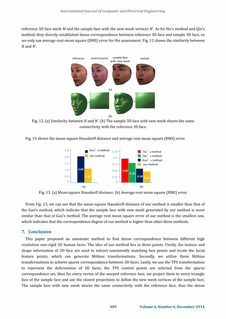
reference 3D face mesh M and the sample face with the new mesh vertices N'. As for Hu’s method and Qin’s
method, they directly established dense correspondence between reference 3D face and sample 3D face, so
we only use average root mean square (RMS) error for the assessment. Fig. 12 shows the similarity between
N and N'.
reference control points sample face with new mesh
sample
(a)
(b) Fig. 12. (a) Similarity between N and N'. (b) The sample 3D face with new mesh shares the same
connectivity with the reference 3D face.
Fig. 13 shows the mean-square Hausdorff distance and average root mean square (RMS) error.
2.04
1.03
10
0
0.5
1.0
1.5
2.0
2.5
0.59 0.43
0
0.25
0.50
0.75
1.0
Guo’s method
our method
Guo’s method
our method
(a) (b)
0.98
101.25
0.76
Qin’s method
Hu’s method
Fig. 13. (a) Mean-square Hausdorff distance. (b) Average root mean square (RMS) error.
From Fig. 13, we can see that the mean-square Hausdorff distance of our method is smaller than that of
the Guo's method, which indicate that the sample face with new mesh generated by our method is more
similar than that of Guo's method. The average root mean square error of our method is the smallest one,
which indicates that the correspondence degree of our method is higher than other three methods.
7. Conclusion
This paper proposed an automatic method to find dense correspondence between different high
resolution non-rigid 3D human faces. The idea of our method lies in three points. Firstly, the texture and
shape information of 3D face are used to extract consistently matching face points and locate the facial
feature points, which can generate Möbius transformations. Secondly, we utilize these Möbius
transformations to achieve sparse correspondence between 3D faces. Lastly, we use the TPS transformation
to represent the deformation of 3D faces, the TPS control points are selected from the sparse
correspondence set, then for every vertex of the warped reference face, we project them to every triangle
face of the sample face and use the closest projections to define the new mesh vertices of the sample face.
The sample face with new mesh shares the same connectivity with the reference face, thus the dense
International Journal of Computer and Electrical Engineering
489 Volume 6, Number 6, December 2014

correspondence between the reference face and the sample face with new mesh is achieved. The
experimental results on BJUT-3D face databases demonstrate that our method achieve better performance
compared with the existing methods.
Acknowledgment
Portions of the research in this paper use the BJUT-3D Face Database collected under the joint sponsor of
National Natural Science Foundation of China, Beijing Natural Science Foundation Program, Beijing Science
and Educational Committee Program.
References
[1] Volker, B., & Thomas, V. (1999). A morphable model for the synthesis of 3D faces. Proceedings of 26th
Annual Conference on Computer Graphics and Interactive Techniques (pp. 187-194). Los Angeles: ACM
Press.
[2] Anguelov, D., Srinivasan, P., Pang, H. C., Koller, D., Thrun, S., & Davis, J. (2004). The correlated
correspondence algorithm for unsupervised registration of Nonrigid surfaces. Proceedings of 18th
Annual Conference on Neural Information Processing Systems (pp. 33-40). Montreal: NIPS Foundation.
[3] Vlasic, D., Brand, M., Pfister, H., & Popovic, J. (July 2005). Face transfer with multilinear models. Acm
Transactions on Graphics, 24, 426-433.
[4] Irfanoglu, M. O., Gokberk, B., & Akarun, L (2004). 3D shape-based face recognition using automatically
registered facial surfaces. Proceedings of 17th International Conference on Pattern Recognition (pp.
183-186). Cambridge: IEEE Press.
[5] Masaki, H., Yoshihisa, S., Taku, K., & Tosiyasu, K. (2001). Topology matching for fully automatic
similarity estimation of 3D shapes. Proceedings of 28th Annual Conference on Computer Graphics and
Interactive Techniques (pp. 203-212). New York: ACM Press.
[6] Gang, P., Xiaobo, Z., Yueming, W., Zhenfang, H., Xiaoxiang, Z., & Zhaohui, W. (November 2013).
Establishing point correspondence of 3D faces via sparse facial deformable model. IEEE Transactions
on Image Processing, 22, 4170-4181.
[7] Tim, H., Bernard, B., & Peter, H. (2001). Dense surface point distribution models of the human face.
IEEE Workshop on Mathematical Methods in Biomedical Image Analysis (pp. 153-160). Kauai: IEEE
Press.
[8] Jianya, G., Xi, M., & Kun, T. (July 2013). Automatic landmark annotation and dense correspondence
registration for 3D human facial images. BMC Bioinformatics, 14, 232-243.
[9] Yongli, H., Mingquan, Z., & Zhongke, W. (2009). An automatic dense point registration method for 3D
faces animation. Proceedings of 2nd International Congress on Image and Signal Processing (pp. 1-6).
Tianjin: IEEE Press.
[10] Wenyu, Q., Yongli, H., Yanfeng, S., & Baocai, Y. (2012). An Automatic Multi-sample 3D Face Registration
Method Based on Thin Plate Spline and Deformable Model. Proceedings of 2012 IEEE International
Conference on Multimedia and Expo Workshops (pp. 453-458). Melbourne: IEEE Press.
[11] Paul, B., & Neil, M. (April 1992). Method for registration of 3-D shapes. Robotics-DL Tentative, 586-606.
[12] Sebastian, W. (1997). Registration of 3-D partial surface models using luminance and depth
information. Proceedings of International Conference on Recent Advances in 3-D Digital Imaging and
Modeling (pp. 93-100). Ottawa: IEEE Press.
[13] David, S. (1996). Fast and accurate shape-based registration. Ph.D. Dissertation, Carnegie Mellon
University, Pittsburgh.
[14] Kari, P. (1999). Multiview registration for large data sets. Proceedings of Second International
International Journal of Computer and Electrical Engineering
490 Volume 6, Number 6, December 2014

Conference on 3-D Digital Imaging and Modeling (pp. 160-168). Ottawa: IEEE Press.
[15] Leslie, I., Natasha, G., & Marc, L. (2003). A hierarchical method for aligning warped meshes. Proceedings
of Fourth International Conference on 3-D Digital Imaging and Modeling (pp. 434-441). Banff: IEEE
Press.
[16] Fred, B. (June 1989). Principal warps: Thin-plate splines and the decomposition of deformations. IEEE
Transactions on Pattern Analysis and Machine Intelligence, 11, 567-585.
[17] Chui, H. L., & Rangarajan, A. (February 2003). A new point matching algorithm for non-rigid
registration. Computer Vision and Image Understanding, 89, 114-141.
[18] Haili, C., James, R., James, D., Robert, S., & Anand, R. (1999). Registration of cortical anatomical
structures via robust 3D point matching. Proceedings of 16th International Conference on Information
Processing in Medical Imaging (pp. 168-181). Visegrad: Springer Press.
[19] Steven, G., Anand, R., Ping, L. C., Suguna, P., & Eric, M. (August 1998). New algorithms for 2d and 3d
point matching: pose estimation and correspondence. Pattern Recognition, 31, 1019-1031.
[20] Anand, R., Haili, C., & Fred, B. (1997). The softassign procrustes matching algorithm. Proceedings of
15th International Conference on Information Processing in Medical Imaging (pp. 29-42). Poultney:
Springer Press.
[21] Yaron, L., & Thomas, F. (August 2009). Möbius voting for surface correspondence. ACM Transactions on
Graphics, 28, 72:1-72:12.
[22] Gabriel, P., & Laurent, C. (August 2006). Geodesic remeshing using front propagation. International
Journal of Computer Vision, 69, 145-156.
[23] Van, K. O., Zhang, H., Hamarneh, G., et al. (June 2011). A survey on shape correspondence. Computer
Graphics Forum, 30, 1681-1707.
[24] Xiangxin, Z., & Deva, R. (2012). Face detection, pose estimation, and landmark localization in the wild.
Proceedings of IEEE Conference on Computer Vision and Pattern Recognition (pp. 2879-2886).
Providence: IEEE Press.
[25] Strang, G. (2007). Computational Science and Engineering. 1st ed., Wellesley, USA: Wellesley-Cambridge,
ch. 2, pp. 128-129.
[26] Chitra, D., & Anil, J. (October 1997). COSMOS-A representation scheme for 3D free-form objects. IEEE
Transactions on Pattern Analysis and Machine Intelligence, 19, 1115-1130.
[27] Nesli, E., & Luc, D. J. (2011). Automatic extraction of facial interest points based on 2D and 3D data.
Proceedings of Conference on the Three-Dimensional Imaging, Interaction, and Measurement, Vol. 7864
(pp. 1-13). San Francisco: SPIE Press.
[28] Tim, H., Bernard, B., Peter, H., & Henry, P. (June 2003). Estimating average growth trajectories in
shape-space using kernel smoothing. IEEE Transactions on Medical Imaging, 22, 747-753.
[29] Multimedia Tech. (2005). The BJUT-3D large-scale Chinese face database. Technical Report, Graphics
Lab, Beijing University of Technology.
Jian Liu was born in Hunan, China in 1978. He received the B.Sc. degree in information
and control engineering from Shanghai Jiaotong University, Shanghai, China in 2000, then
received the M.Sc. degree in information and communication engineering from National
University of Defense Technology, Changsha, China in 2002, Currently, he is pursuing the
Ph.D. degree with the College of Electronic Science and Engineering, National University
of Defense Technology. He is a lecturer of the College of Electronic Science and
Engineering, National University of Defense Technology. His current research interests include computer
vision, image processing and digital geometry processing.
International Journal of Computer and Electrical Engineering
491 Volume 6, Number 6, December 2014

Quan Zhang was born in Shanghai, China in 1974. He received the B.Sc. and Ph.D.
degrees in information and communication engineering from National University of
Defense Technology, Changsha, China in 1996 and 2001, respectively. He is an associate
professor of the College of Electronic Science and Engineering, National University of
Defense Technology. His current research interests include category theory, quantum
communications, and computer vision.
Chaojing Tang was born in Jiangsu, China in 1962. He received the M.Sc. degree in
electronic from National University of Defense Technology, Changsha, China in 1986, then
received the Ph.D. degree in information and communication engineering from National
University of Defense Technology, Changsha, China in 2003. He is a professor of the
College of Electronic Science and Engineering, National University of Defense Technology,
and he is also with the board of directors of the China Communication Institute. His
current research interests include quantum communications, space communications networks and
computer vision.
International Journal of Computer and Electrical Engineering
492 Volume 6, Number 6, December 2014