essex pb&r corporation - saywell international · inspection and fault isolation flow charts...
TRANSCRIPT

Essex PB&R Corporation
8007 Chivvis Drive • St. Louis, MO 63123 (314) 351-6116 • (800) 296-7587 • Fax (314) 351-7181
Essex Crewmember Protective Breathing Equipment (PBE)
User Reference and Procedures Manual
for
FAA TSO-C116 & TSO-C99 Approved United Kingdom - Civil Aviation Authority (CAA) Approved
European Aviation Safety Agency (EASA) Approved Civil Aviation Authority of China (CAAC) Approved Brazilian Civil Aviation Authority (ANAC) Approved
Crewmember PBE Assemblies
Part No: DP3113( ) and DP3113(A) Model No: MR-100( )
and Model No: 4566M37-B-( )
Document No: PRM-01, Revision: 14 Dated:01/29/09

Essex PB&R Corporation User Reference and Procedures Manual for the Essex Crewmember PBE
2
TABLE OF CONTENTS
TABLE OF CONTENTS 2 REVISION RECORD SHEET 4 FAA TSO-C116, TSO-C99, CAA, EASA & CAAC APPROVED PBE ASSEMBLIES 5 CROSSOVER TABLE 6 1. DESCRIPTION AND OPERATION 7
General Description of Equipment 7 Purpose of the Equipment 7 Hood Shell Construction 7 Oxygen System 7 Service/End-of-Service Indicator 9 Packaging and Stowage Containers 9 Compliance 9 Useful Service Life 9
Operating Features 9
Tamper-Evident Seals 9 Pouch Access 10 Breathing System 10 Time Required to Put On and Take Off Hood 10 Maneuverability During Use 10 Carbon Dioxide Control 11 Interpersonal Communications 11
Operating Steps 14
General Sequence of Steps 14 Accessing the Essex Crewmember PBE Equipment Pouch 14 Open the Sealed Pouch 28 Activate the Oxygen Supply 30
Don the Activated Hood 31 Wearing the Hood 33 Remove and Discard the Hood 34 Dispose of Equipment Properly 34
Document No: PRM-01, Revision: 14 Dated:01/29/09

Essex PB&R Corporation User Reference and Procedures Manual for the Essex Crewmember PBE
3
2. INSPECTION AND FAULT ISOLATION 35
General 35 Inspection Procedures 35 Statement of Warranty 40 Return Procedures 41
3. REPAIR 43
General 43 Refitting Broken, Torn or Missing Tamper-Evident Seals 43 Realigning Equipment Pouch within Stowage Containers 45
4. INSTALLATION AND ASSEMBLY 47
Mounting Locations 47
Installation Steps 47
Open-Ended Bracket 47 Closed-Ended Bracket 48 Flange-Mounted Stowage Case 49 Bracket-Mounted Stowage Case 49 Flame-Resistant Fabric Container 49 Internal-Mounted Stowage Case 49 Bracket-Mounted Stowage Case (Bracket provided) 50
5. RETROFIT KITS 50 6. THE ESSEX CREWMEMBER PBE TRAINING UNIT 53
Introduction 53 Operating Features 53
Operating Steps 53
Plastic Training Liner (Optional) 53 General Sequence of Steps 54 Verbal Communications 54
Replacing Torn or Damaged Neck Seals 54 Maintenance Procedures 55 Handling and Storage 55
Document No: PRM-01, Revision: 14 Dated:01/29/09

Essex PB&R Corporation User Reference and Procedures Manual for the Essex Crewmember PBE
4
Revision Record Sheet
Rev
# Date Description of Revision
9 12/14/04 Added Revision Sheet, page 4 to manual; added new model number MR-10050N to manual; revised Statement of Warranty; and re-numbered all pages accordingly.
10
01/03/06 Change all address and phone number references to the new, St. Louis location; added required changes that incorporate the elimination of the Visual Service Indicator (VSI) from PBE Model No’s MR-10034N, MR-10036N, MR-10037N and MR-10042N; and added third type of barrier pouch (one with yellow nylon pull strap).
11
02/10/06 Revision includes: clarification of the PBE Stowage Bracket configurations of those PBE’s that had the Visual Service Indicator (VSI) eliminated – changed “Manufactured before and after” to “Shipped or Repaired before and after”; and added photos of top view of PBE Model #’s MR-10034N, MR-10036N, & MR-10037N - Pages 17, 19, 20, and 22 were revised. On cover page of manual, Model No: 45667M37-B- ( ) was changed to Model No: 4566M37-B-( ).
12
7/31/06 Revision includes: adding new AS9100B & ISO9001-200 Certified logo; adding approval by the European Aviation Safety Agency (EASA), & the Civil Aviation Authority of China (CAAC) to cover page and to 1.A.(6) Compliance; and a revised Statement of Warranty that changed the warranty period from 10 years to 10 years 6 months and added an additional “foregoing warranty statement”.
13
8/29/07 Added new PBE, Model # MR-10051N to manual; and deleted Two-Handled Pouch from manual (units of this nature are no longer in service).
14
1/29/09 Added approved by ANAC to cover sheet and to paragraph 1. A. (6) on page 9. Also, revised Inspection and Fault Isolation Flow Charts – Figures 19 & 20 on pages 38 & 39.
Document No: PRM-01, Revision: 14 Dated:01/29/09

Essex PB&R Corporation User Reference and Procedures Manual for the Essex Crewmember PBE
5
FAA TSO-C116, TSO C-99, CAA, EASA AND CAAC APPROVED PBE ASSEMBLIES ASSEMBLIES MANUFACTURED AFTER OCTOBER 9, 1996: Model Number Description MR-10021N Crewmember PBE - Training Unit MR-10022N Crewmember PBE with Concealed Mounting Holes and Viewing Window MR-10034N Crewmember PBE with Bracket Mounted Case (Stowage Box A) MR-10035N Crewmember PBE with Flame-Resistant Fabric Pouch MR-10036N Crewmember PBE with Bracket Mounted Case (Stowage Box C) MR-10037N Crewmember PBE with Flange Case (Stowage Box B) MR-10039N Crewmember PBE with Bracket Mounted Case and Viewing Window MR-10042N Crewmember PBE with Open Ended Stowage Bracket MR-10046NS Crewmember PBE with Closed Ended Straight Strap Bracket MR-10046NY Crewmember PBE with Closed Ended Y-Strap Bracket MR-10046RS Retrofit of Returned, Crewmember PBE into a Closed Ended
Straight Strap Bracket MR-10046RY Retrofit of Returned, Crewmember PBE into a Closed Ended
Y-Strap Bracket MR-10047N Crewmember PBE without stowage Bracket MR-10049N Crewmember PBE with Molded Plastic Closed Ended Y-Strap Bracket and Humidity Indicator Window MR-10050N Crewmember PBE with Concealed Mounting Holes and Viewing Window MR-10051N Crewmember PBE with Flame-Resistant Fabric Pouch ASSEMBLIES MANUFACTURED PRIOR TO OCTOBER 9, 1996: Model Number Description 4566M27-B-021N Crew PBE Training Unit 4566M37-B-032N Crew PBE in Barrier Pouch w/ VSI 4566M37-B-034N Crew PBE with Bracket-Mounted Case (Stowage Box A) 4566M37-B-035N Crew PBE with Flame-Resistant Fabric Pouch 4566M37-B-036N Crew PBE with Bracket-Mounted Case (Stowage Box C) 4566M37-B-037N Crew PBE with Flange Case (Stowage Box B) 4566M37-B-042NM Crew PBE with Open Ended Stowage Bracket 4566M37-B-046NS Crew PBE with Closed Ended Straight Strap Bracket 4566M37-B-046NY Crew PBE with Closed Ended Y-Strap Bracket 4566M37-B-046RS Retrofit of Returned, Crew PBE into a Closed Ended Straight Strap Bracket 4566M37-B-046RY Retrofit of Returned, Crew PBE into a Closed Ended
Y-Strap Bracket 4566M37-B-047N Crew PBE without stowage Bracket
Document No: PRM-01, Revision: 14 Dated:01/29/09

Essex PB&R Corporation User Reference and Procedures Manual for the Essex Crewmember PBE
6
Crossover Table for Current and Old Part and Model Numbers
Old Model Number
Current Model Number
Current Part Number
DP3113(A) 4566M37-B( ) DP3113( )
4566M27-B-021N MR-10021N MR-10022N
4566M37-B-032N 4566M37-B-034N MR-10034N 4566M37-B-035N MR-10035N 4566M37-B-036N MR-10036N 4566M37-B-037N MR-10037N
MR-10039N 4566M37-B-042NM MR-10042N 4566M37-B-046NS MR-10046NS 4566M37-B-046NY MR-10046NY 4566M37-B-046RS MR-10046RS 4566M37-B-046RY MR-10046RY 4566M37-B-047N MR-10047N
MR-10049N MR-10050N MR-10051N
Note: The configuration of the old Model Numbers and the Current Model and Part Numbers
are identical. For example: DP3113 ( ) is identical in configuration to 4566M37-B( ), MR-10034N is identical in configuration to 4566M37-B-034N, MR-10042N is identical in configuration to 4566M37-B-042NM, etc. Part Number DP3113 ( ) is the Essex Crewmember PBE without a barrier pouch or any type of stowage bracket. The Current Model Numbers designate the type of bracket configuration that Part Number DP3113 ( ) and DP3113(A) are assembled into.
Document No: PRM-01, Revision: 14 Dated:01/29/09

Essex PB&R Corporation User Reference and Procedures Manual for the Essex Crewmember PBE
7
1. DESCRIPTION AND OPERATION A. General Description of Equipment
(1) Purpose of the Equipment
The Essex PB&R Corp. (Essex) Crewmember PBE (Ref. Figure 1 on page 8) is a self-contained, portable, personal breathing device designed to safeguard the wearer from the effects of smoke, carbon dioxide, harmful gases, and oxygen deficiency while managing in-flight fire, smoke or fume emergencies.
The equipment improves the wearer’s visibility in smoke-filled compartments, protects the head and face from melting or dripping plastics, and shields the head against brief exposure to heat and flame. The primary functional component in the Essex Crewmember PBE is a portable hood that contains both a breathable oxygen supply and lithium hydroxide (LiOH) scrubber panels that absorb exhaled carbon dioxide. The hood has a self-fitting neck opening that seals out contaminants, retains the oxygen and keeps the hood inflated during use. The entire unit is hermetically sealed at Essex PB&R Corp. to protect the LiOH scrubber panels from outside air.
(2) Hood Shell Construction
The Essex Crewmember PBE hood is fabricated from a durable, tear-resistant combination of polyimide and PFA films. The hood’s inner surface has an anti-fog coating to improve visibility.
(3) Oxygen System
The Essex Crewmember PBE has two oxygen cylinders. Together they hold a minimum of 36 liters of Aviator Grade oxygen. These cylinders meet SAE Standard AS 8010 for breathing-oxygen purity, and have rupture protection in case of over pressurization.
Document No: PRM-01, Revision: 14 Dated:01/29/09

Essex PB&R Corporation User Reference and Procedures Manual for the Essex Crewmember PBE
8
Overall View of Essex Crewmember PBE (As Worn)
Figure 1
Document No: PRM-01, Revision: 14 Dated:01/29/09

Essex PB&R Corporation User Reference and Procedures Manual for the Essex Crewmember PBE
9
(4) Service/End-of-Service Indicator
The Essex Crewmember PBE features a battery-powered green and red light Service/End-of-Service Indicator. Mounted slightly below eye level on the left inner side of the hood, this indicator functions as a secondary indicator for monitoring oxygen activation, reassuring the wearer that the equipment is functioning, and signaling when the equipment’s service life is ended. (Ref. Figure 1 on page 8).
(5) Packaging and Stowage Containers
The Essex Crewmember PBE alone weighs 3.2 lbs (1.45 kg). It is folded and packaged in a moisture resistant pouch, and stowed in a protective container (made either from molded plastic, metal, or from Flame-Resistant fabric, depending on model). A packaged Crewmember PBE is normally installed within 3 ft (.9 m) of each required on-board fire extinguisher. Each airline should receive regulatory approval for installation locations.
(6) Compliance
The Essex Crewmember PBE complies with the requirements of FAA Action Notice A8150.2 and is approved according to FAA TSO-C116 and TSO-C99. The Essex Crewmember PBE is also approved: under BCAR B4-8, United Kingdom – Civil Aviation Authority (CAA) requirements, thereby we are also approved by the European Aviation Safety Agency (EASA); by the Civil Aviation Authority of China (CAAC); and by the Brazilian Civil Aviation Authority (ANAC).
(7) Useful Service Life (Warranty Period)
The Essex Crewmember PBE has a 10-year 6-month, warranted, useful service life, beginning from the date of manufacture.
B. Operating Features
(1) Tamper-Evident Seals
To ensure that the Essex Crewmember PBE has not been tampered with, units in hard case stowage containers have tamper-evident seals. For closed stowage brackets (MR-10046NS, and MR-10046NY), the tamper-evident seals are the red-knotted cable ties (Type A) or the tamper-evident labels (Type C). (Ref. Figure 2 on page 13) For open-ended stowage brackets (MR-10042N and 4566M37-B-042NM) the tamper-
Document No: PRM-01, Revision: 14 Dated:01/29/09

Essex PB&R Corporation User Reference and Procedures Manual for the Essex Crewmember PBE
10
evident seals are the green plastic padlocks (Type B). (Ref. Figure 2 on page 13)
For bracket-mounted, flange-mounted, or internal-mounted stowage cases ((MR-10022N, 34N, 36N, 37N, 39N, and 50N) and (4566M37-B-034N, -036N, and -037N)), the tamper-evident seals are the tamper-evident labels (Type C). (Ref. Figure 2 on page 13)
For the molded stowage bracket (MR-10049N), the tamper-evident seals are the tamper-evident labels (Type C). (Ref. Figure 2 on page 13) There are no seals for units stowed in Flame-Resistant fabric containers (MR-10035N, MR-10051N and 4566M37-B-035N).
(2) Pouch Access
The sealed barrier pouch containing the Essex Crewmember PBE is easily accessed and removed from its stowage container (Ref. para. 1.C. (2) on page 14). A force of approximately 18-28 pounds will be required to remove the pouch, or to lift the lid & break the tamper-evident seals.
(3) Breathing System
Once the pouch is removed from its container and opened, oxygen flow is initiated by snapping the two cylinders apart, which in turn activates the flashing green light on the Service/End-of-Service Indicator. One bottle releases oxygen rapidly, whereas the second bottle discharges oxygen slowly. An audible hissing sound and inflation of the unit within (2) minutes indicates the PBE is operating properly. Once donned, the Essex Crewmember PBE will protect the wearer for up to 15 minutes. Although both bottles will completely discharge in 8 to 10 minutes, enough oxygen will remain for the full, specified 15 minutes of respiratory protection. When the unit deflates to the point where it touches the wearer’s head and face, or when the red light on the Service/End-of-Service Indicator flashes, the unit’s useful life has ended and must be removed.
The Essex Crewmember PBE operates at a positive pressure. The neck seal acts as a relief valve to prevent excessive pressure from building up inside the hood.
(4) Time Required to Put On and Take Off Hood
A trained user can access and don the hood in approximately 15 seconds. It can be removed in less than 5 seconds.
Document No: PRM-01, Revision: 14 Dated:01/29/09

Essex PB&R Corporation User Reference and Procedures Manual for the Essex Crewmember PBE
11
(5) Maneuverability During Use
The Essex Crewmember PBE does not restrict or interfere with normal body movements. Even when fully inflated, it is compact enough that the wearer can pass through openings as small as 18 in x 18 in (460 mm x 460 mm).
(6) Carbon Dioxide Control
Special fabric panels inside the hood control carbon dioxide buildup. These panels contain a dustless lithium hydroxide absorbent sealed inside a double walled membrane, which keeps carbon dioxide concentrations at safe levels during the hood’s 15-minute service period.
(7) Interpersonal Communications
Persons wearing the Essex Crewmember PBE can communicate by unaided voice with other people wearing hoods, at a distance of at least 13.1 ft (4 m) away. When using an interphone, megaphone or microphone, it may be necessary to pull the skirt of the hood down so the scrubber is below mouth level. Press the phone unit firmly against the hood film in front of the mouth as shown in Figure 1A on page 12, minimizing the gap between the mouth and device.
Document No: PRM-01, Revision: 14 Dated:01/29/09

Essex PB&R Corporation User Reference and Procedures Manual for the Essex Crewmember PBE
12
Megaphone Operation Illustration
Figure 1A
Document No: PRM-01, Revision: 14 Dated:01/29/09

Essex PB&R Corporation User Reference and Procedures Manual for the Essex Crewmember PBE
13
Types of Tamper-Evident Seals
Figure 2
Document No: PRM-01, Revision: 14 Dated:01/29/09

Essex PB&R Corporation User Reference and Procedures Manual for the Essex Crewmember PBE
14
C. Operating Steps
(1) General Sequence of Steps
The operating steps for an Essex Crewmember PBE are generally the same for all models, but access to the pouch will vary somewhat depending on type of stowage container installed on the aircraft.
The normal operating sequence is: access the PBE, open the equipment pouch, activate the system, don the hood, wear it as needed, then remove and dispose of it after use.
The minor differences in accessing the pouch from its stowage container are noted below.
(2) Accessing the Essex Crewmember PBE Equipment Pouch
Follow the pouch removal procedures that apply to your appropriate stowage container.
(a) Open-Ended, Stowage Bracket Container (MR- 10042N and 4566M37-B- 042NM). (Ref. Figure 9 on page 22) Grasp the end of the pouch firmly using both hands, if possible. Sharply pull the pouch out of its bracket. This sharp pull will break the two tamper-evident seals and free the equipment pouch from the bracket. Approximately 18 to 28 pounds of force will be required to remove the pouch from the bracket.
(b) Closed Bracket Stowage Container (MR-10046NS, MR-10046NY, and MR-10049N). (Ref. Figures 10, 11, and 12 on pages 23, 24, and 25 respectively) Closed bracket stowage containers can be opened by grasping the strap attached to the lid or by grasping the lid itself, and pulling sharply to break the tamper-evident seals. Approximately 18 to 28 pounds of force will be required to lift the lid and break the tamper-evident seals. Grab the end of the pouch and pull it from the bracket.
(c) Flange-Mounted Stowage Case (MR-10037N and 4566M37-B-037N). (Ref. Figure 7 on page 20)
Lift up the lid latch/clasp and pull the box lid open sharply. This will break the tamper-evident seals on the container. Approximately 18 to 28 pounds of force will be required to lift the lid and break the tamper-evident seals. Grasp the end of the pouch or grab the yellow nylon strap (if so equipped) and pull it from the container.
Document No: PRM-01, Revision: 14 Dated:01/29/09

Essex PB&R Corporation User Reference and Procedures Manual for the Essex Crewmember PBE
15
(d) Bracket-Mounted Stowage Case (MR-10034N, MR-10036N, 4566M37-B-
034N, 4566M37-B-036N, and MR-10039N). (Ref. Figures 4, 6, and 8 on pages 17, 19, and 21 respectively)
If the stowage container is strapped to a supporting bracket (as may be the case in certain aircraft installations), first loosen the straps holding the container, then remove the stowage container.
This container has handles on both top and bottom, or on one side. Hold it by the appropriate carrying handle, then unlatch the lid. Open the lid sharply to break the tamper-evident seals on the container. Approximately 18 to 28 pounds of force will be required to lift the lid and break the tamper-evident seals. Grasp the end of the pouch or grab the yellow nylon strap (if so equipped) and remove it from the container.
(e) Flame-Resistant Fabric Stowage Container (MR-10035N, MR-10051N and 4566M37-B-035N). (Ref. Figure 5 on page 18 and/or Figure 13A on page 27)
Pull on the nylon tabs to release the container’s flaps. This container can be opened on three sides. Once the flaps are free, remove the equipment pouch from the container.
(f) Internal-Mounted Stowage Case (MR-10022N) (Ref. Figure 3 on page 16)
Slide the lid latch/clasp and pull the box lid open sharply. This will break the tamper-evident seals on the container. Approximately 18 to 28 pounds of force will be required to lift the lid and break the tamper-evident seals. Grasp the yellow nylon strap and pull it from the container.
(g) Internal-Mounted Stowage Case (MR-10050N)
(Ref. Figure 13 on page 26) Unlatch both clasps and open lid by grasping the strap attached to the lid and pull sharply to break the tamper-evident seals. Approximately 18 to 28 pounds of force will be required to lift the lid and break the tamper-evident seals. Grab the end of the pouch and pull it from the container.
Document No: PRM-01, Revision: 14 Dated:01/29/09

Essex PB&R Corporation User Reference and Procedures Manual for the Essex Crewmember PBE
16
Accessing the Essex PBE Pouch from the Internal-Mounted Stowage Case
Figure 3
Weight 4.7 lbs H W D
Inches 9 3/4 8 15/32 3 1/4 cm 24.77 21.51 8.26
Document No: PRM-01, Revision: 14 Dated:01/29/09
N
MR 10022MR-10022N

Essex PB&R Corporation User Reference and Procedures Manual for the Essex Crewmember PBE
17
Accessing the Essex PBE Pouch from the Bracket-Mounted Stowage Case
Bracket with Visual Service Indicator (VSI) – Shipped or Repaired before 12/01/05
Bracket without VSI and with Inspection Window – Shipped or Repaired after 12/01/05
Clear Inspection Window showing: Serial # / Manufacturer Bar Code Label; Humidity Indicator; and
Replace By Date Label
MR-10034N – Top ViewMR-10034N
Figure 4
Weight: 4.6 lbs Size: 9 ¾” H x 8 15/32” W x 3 ¼” D
(24.77 cm H x 21.51 cm W x 8.26 cm D)
Document No: PRM-01, Revision: 14 Dated:01/29/09

Essex PB&R Corporation User Reference and Procedures Manual for the Essex Crewmember PBE
18
Accessing the Essex PBE Pouch from the
Flame-Resistant Fabric Stowage Container
MR-10035N
Figure 5
Weight 3.3 lbs H W D
Inches 11 16 2 cm 27.94 40.64 5.08
Document No: PRM-01, Revision: 14 Dated:01/29/09

Essex PB&R Corporation User Reference and Procedures Manual for the Essex Crewmember PBE
19
Accessing the Essex PBE Pouch from the Bracket-Mounted Stowage Case
Bracket with Visual Service Indicator (VSI) – Shipped or Repaired before 12/01/05
Clear Inspection Window showing: Serial # / Manufacturer Bar Code Label; Humidity Indicator; and
Replace By Date Label
MR-10036N
Bracket without VSI and with Inspection Wind
Figure
Weight: 4.6 lbs Size: 9 ¾” (24.7
Document No: PRM-01, Revisi
MR-10036N - Top View
ow – Shipped or Repaired after 12/01/05
6
H x 8 15/32” W x 3 ¼” D 7 cm H x 21.51 cm W x 8.26 cm D)
on: 14 Dated:01/29/09

Essex PB&R Corporation User Reference and Procedures Manual for the Essex Crewmember PBE
20
Accessing the Essex PBE Pouch from the Flange-Mounted Stowage Case
Bracket with Visual Service Indicator (VSI) – Shipped or Repaired before 12/01/05
MR-10037N – Top View
MR-10037N
Bracket without VSI and with Inspection Window –
Figure 7
Weight: 4.6 lbs Size: 9 5/16” H (23.65 cm
Document No: PRM-01, Revision: 14
Clear Inspection Window showing: Serial # / Manufacturer Bar Code Label; Humidity Indicator; and
Replace By Date Label
Shipped or Repaired after 12/01/05
x 9 5/8” W x 3 ¼” D H x 24.45 cm W x 8.26 cm D)
Dated:01/29/09

Essex PB&R Corporation User Reference and Procedures Manual for the Essex Crewmember PBE
21
Accessing the Essex PBE Pouch from the Bracket-Mounted Stowage Case with Information Viewing Window
Figure 8
Weight 4.9 lbs H W D
Inches 9 3/4 8 15/32 3 1/4 cm 24.77 21.51 8.26
Document No: PRM-01, Revision: 14 Dated:01/29/09

Essex PB&R Corporation User Reference and Procedures Manual for the Essex Crewmember PBE
22
Accessing the Essex PBE Pouch from the Open-Ended Stowage Bracket Container
MR-10042N
MR-10042N with Visual Service Indicator (VSI) – Shipped or Repaired before 1/01/05
MR-10042N
MR-10042N without Visual Service Indicator (VSI) – * Shipped or Repaired after 1/01/05
Figure 9
Weight: 4.6 lbs Size: 13 ¼” H x 11 11/32” W x 2 ½” D (33.66 cm H x 28.81 cm W x 6.35 cm D) * A black Cap Plug may also be used to plug the VSI hole.
Document No: PRM-01, Revision: 14 Dated:01/29/09

Essex PB&R Corporation User Reference and Procedures Manual for the Essex Crewmember PBE
23
Accessing the Essex PBE Pouch from the Closed Stowage Bracket Container
Figure 10
Weight 5.7 lbs H W D
Inches 13 5/8 11 11/32 2 3/4 cm 34.61 28.81 6.99
Document No: PRM-01, Revision: 14 Dated:01/29/09

Essex PB&R Corporation User Reference and Procedures Manual for the Essex Crewmember PBE
24
Accessing the Essex PBE Pouch from the Closed Stowage Bracket Container
Figure 11
Weight 5.7 lbs
H W D Inches 13 5/8 11 11/32 2 3/4
cm 34.61 28.81 6.99
Document No: PRM-01, Revision: 14 Dated:01/29/09

Essex PB&R Corporation User Reference and Procedures Manual for the Essex Crewmember PBE
25
Accessing the Essex PBE Pouch from the Closed Stowage Bracket Container
Figure 12
Weight 4.9 lbs
H W D Inches 13 1/2 11 1/2 2 3/4
cm 34.29 29.21 6.99
Document No: PRM-01, Revision: 14 Dated:01/29/09

Essex PB&R Corporation User Reference and Procedures Manual for the Essex Crewmember PBE
26
Accessing the Essex PBE Pouch from the Internal-Mounted Stowage Case
MR-10050N
Figure 13
Weight 5.0 lbs
H W D Inches 12 3/8 12 3/8 2 3/4
cm 31.43 31.43 6.99
Document No: PRM-01, Revision: 14 Dated:01/29/09

Essex PB&R Corporation User Reference and Procedures Manual for the Essex Crewmember PBE
27
Accessing the Essex PBE Pouch from the Flame-Resistant Fabric Stowage Container
MR-10051N
Front View
MR-10051N
Rear View
Figure 13A
Weight 3.3 lbs H W D
Inches 12 3/4 11 3/4 2 cm 32.39 29.85 5.08
Document No: PRM-01, Revision: 14 Dated:01/29/09

Essex PB&R Corporation User Reference and Procedures Manual for the Essex Crewmember PBE
28
(3) Open the Sealed Pouch (Ref. Figure 14 on page 29)
(a) There are two (2) types of equipment pouches used with the Essex PBE.
1) The Tear Open Pouch is recognized by the bright red tear strip at the top of the pouch. To open, grasp the pouch in one hand at either of the small red grip tabs located on each side of the pouch. With the other hand grasp the red tear strip and tear across the pouch in the direction of the arrows. This pouch may be opened from either direction.
2) The Tear Open Pouch with the Yellow Nylon Pull Strap is recognizable by the
bright red tear strip at the top of the pouch and the yellow pull strap at the bottom of the pouch. To open, grasp the pouch in one hand at either of the small red grip tabs located on each side of the pouch. With the other hand grasp the red tear strip and tear across the pouch in the direction of the arrows. This pouch may be opened from either direction.
NOTE: HOLD THE POUCH TIGHTLY BETWEEN THE KNEES
WHILE OPENING IT TO PREVENT THE HOOD FROM FALLING TO THE FLOOR. (b) Remove the hood from the pouch, then discard the pouch.
CAUTION: BEFORE ACTIVATING THE OXYGEN, REMOVE OBJECTS FROM AROUND THE HEAD (SUCH AS HAIR COMBS, LONG EARRINGS OR JEWELRY) TO PREVENT THEM FROM PUNCTURING THE HOOD OR DAMAGING THE NECK SEAL.
Document No: PRM-01, Revision: 14 Dated:01/29/09

Essex PB&R Corporation User Reference and Procedures Manual for the Essex Crewmember PBE
29
C. Tear Open Pouch with Nylon Pull Strap (Pouch opens the same as B. above)
Opening the Sealed Equipment Pouch to Remove the Essex PBE
Figure 14
Document No: PRM-01, Revision: 14 Dated:01/29/09
Essex PB&R Corporation User Reference and Procedures Manual for the Essex Crewmember PBE
30
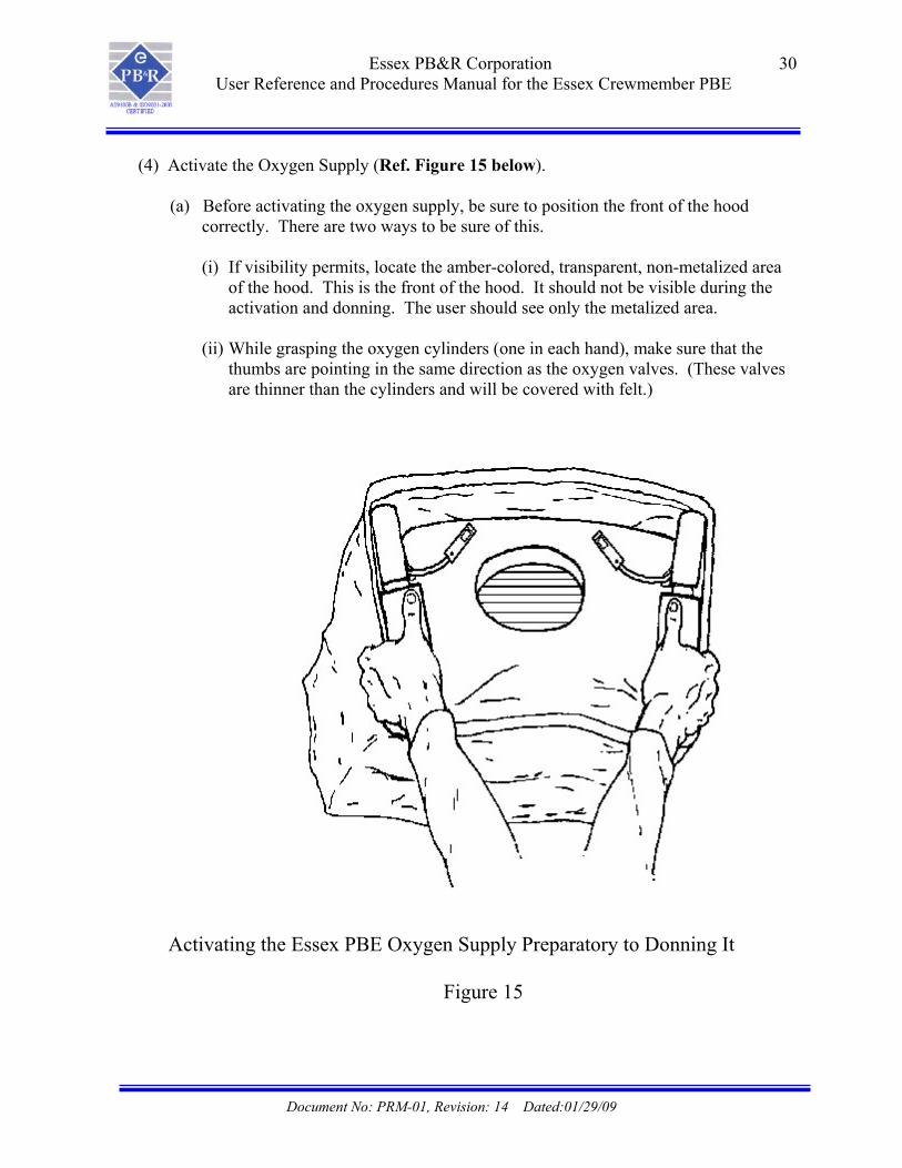
(4) Activate the Oxygen Supply (Ref. Figure 15 below).
(a) Before activating the oxygen supply, be sure to position the front of the hood correctly. There are two ways to be sure of this.
(i) If visibility permits, locate the amber-colored, transparent, non-metalized area
of the hood. This is the front of the hood. It should not be visible during the activation and donning. The user should see only the metalized area.
(ii) While grasping the oxygen cylinders (one in each hand), make sure that the
thumbs are pointing in the same direction as the oxygen valves. (These valves are thinner than the cylinders and will be covered with felt.)
Activating the Essex PBE Oxygen Supply Preparatory to Donning It
Figure 15
Document No: PRM-01, Revision: 14 Dated:01/29/09

Essex PB&R Corporation User Reference and Procedures Manual for the Essex Crewmember PBE
31
Unfold the hood far enough to reveal the oxygen cylinders. Grasp each securely, one in each hand, with thumbs pointing toward the valves (the thin end of each bottle).
Sharply snap the oxygen cylinders away from each other. This sharp action pulls on the two cords that trigger the oxygen flow and activates the green light on the Service/End-of-Service Indicator.
NOTE: DO NOT PULL THE OXYGEN CYLINDERS APART SLOWLY. DOING SO WILL INCREASE THE FORCE NECESSARY TO ACTIVATE THE EQUIPMENT.
WARNING: TO AVOID LOSING OXYGEN ONCE THE SYSTEM IS
ACTIVATED, AND TO MINIMIZE THE AMOUNT OF TOXINS THAT MAY ENTER THE HOOD, DON THE HOOD PROMPTLY AFTER ACTIVATION.
(5) Don the Activated Hood (Ref. Figure 16 on page 32)
(a) The sharp snapping action required to activate the equipment will reveal the self-fitting elastic neck seal.
(b) Hold the equipment at about waist level. Place both hands inside the neck seal opening, with palms facing each other. Stretch the neck seal open by spreading the hands apart.
(c) Lift up the opened hood with both hands, and then lower it down over the head until it fits securely around the neck.
NOTE: EYEGLASS WEARERS SHOULD FIRST POSITION THE NECK SEAL AGAINST THE BACK OF THE HEAD, THEN PULL THE HOOD FORWARD AND DOWN OVER THE EYEGLASSES.
NOTE: MAKE SURE THAT SHIRT COLLARS OR SCARVES DO
NOT INTERFERE WITH THE NECKSEAL.
Document No: PRM-01, Revision: 14 Dated:01/29/09

Essex PB&R Corporation User Reference and Procedures Manual for the Essex Crewmember PBE
32
Donning the Activated Essex PBE
Figure 16
WARNING: AFTER DONNING THE HOOD, DO NOT OPEN THE NECK SEAL EXCEPT TO QUICKLY TUCK IN HAIR, OR TO ADJUST THE HOOD’S POSITION. HAVE ANOTHER PERSON HELP IF NEEDED.
Document No: PRM-01, Revision: 14 Dated:01/29/09

Essex PB&R Corporation User Reference and Procedures Manual for the Essex Crewmember PBE
33
(d) The equipment is donned correctly if the oxygen cylinders are positioned over the
shoulders under each ear and the transparent amber-colored area is facing front.
If the hood is accidentally donned backwards, do not remove it. Instead, rotate the hood until it is properly positioned.
WARNING: IF EITHER OF THE FOLLOWING CONDITIONS EXIST, REMOVE THE EQUIPMENT AND DISCARD IT IMMEDIATELY:
(1) THE SOUND OF THE OXYGEN FLOW IS INAUDIBLE IMMEDIATELY AFTER DONNING.
(2) THE HOOD DOES NOT INFLATE WITHIN 2 TO 3 MINUTES, OR COLLAPSES.
WARNING: DO NOT PASS ALONG AN ACTIVATED HOOD TO ANOTHER PERSON ONCE IT IS DONNED. THIS WILL CAUSE OXYGEN TO ESCAPE AND CAN SUBSTANTIALLY REDUCE PERFORMANCE.
(6) Wearing the Hood
Full hood inflation takes from 2 to 3 minutes but the equipment is ready for use immediately. During the first few minutes the oxygen makes a noticeably loud, hissing sound that gradually diminishes. The oxygen stops flowing after 8 to 10 minutes, but enough remains in the hood for a full 15 minutes of usage.
WARNING: IF THE HOOD COLLAPSES AROUND THE FACE AT ANYTIME, REMOVE IT IMMEDIATELY AND OBTAIN A NEW ONE. WARNING: DO NOT APPROACH ANY CLOSER TO A FIRE OR FLAMES THAN THE NORMAL RANGE OF AN APPROVED FIRE EXTINGUISHER, SINCE THE USER WILL ORDINARILY NOT BE WEARING FIRE- RESISTANT CLOTHING. (a) Observe the flashing green Service/End-of-Service Indicator light inside the hood,
located to the left and just below eye level. When the red light flashes with the green light, or when the hood collapses, move immediately to a safe area and remove the unit.
Document No: PRM-01, Revision: 14 Dated:01/29/09

Essex PB&R Corporation User Reference and Procedures Manual for the Essex Crewmember PBE
34
(b) Note that warming and condensation inside the hood may occur. If this interferes with vision, press the hood against the face to wipe away condensation.
(c) Some users may experience mild ear popping as the air pressure inside the hood
gradually increases due to the oxygen flow.
(d) Interphone, megaphone and microphone communication are possible while the hood is still inflating and during its operation. Press the phone device directly against the hood for best operation. Or, place the phone device up against the Adam’s apple.
WARNING: DO NOT REMOVE THE HOOD WHILE NEAR SPARKS OR OPEN FLAME. SOME RESIDUAL OXYGEN MAY REMAIN IN BOTH THE HOOD AND HAIR. (7) Remove and Discard the Hood
Remove the PBE if the hood collapses over the face, or as soon as the red light in the Service/End-of-Service indicator comes on, or immediately after the emergency is under control, whichever comes first.
(a) Leave the area of the emergency before attempting to remove the hood.
(b) To remove the hood, insert both hands under the neck seal, beneath the chin. Lift the hood up and out to clear the face.
NOTE: EYEGLASS WEARERS SHOULD FIRST INSERT BOTH HANDS UNDER THE NECK SEAL, THEN PULL THE HOOD FORWARD AND OUTWARD, LIFTING IT UP OVER THE HEAD TO AVOID DISLODGING THE EYEGLASSES.
(8) Dispose of Equipment Properly
WARNING: DO NOT CUT INTO THE WHITE PANELS AROUND THE COLLAR OR UP THE BACK OF THE HOOD. THIS MAY EXPOSE LITHIUM HYDROXIDE AND LITHIUM CARBONATE, WHICH CAN IRRITATE THE SKIN AND BREATHING PASSAGES.
Follow these steps in properly disposing of spent equipment.
(a) Cut the neck seal into four quadrants.
Document No: PRM-01, Revision: 14 Dated:01/29/09

Essex PB&R Corporation User Reference and Procedures Manual for the Essex Crewmember PBE
35
(b) Cut a hole in the amber-colored transparent film area at least 5 inches across.
(c) If the oxygen system has not yet been activated, do so before disposing of the equipment.
(i) Handle the oxygen disposal in an area where there is no potential danger from sparks or other fire hazards. (ii) After equipment has been activated, leave it alone for at least one hour, so
that all residual oxygen will dissipate.
(d) Dispose of the hood in compliance with federal, state and local EPA regulations. Contact the appropriate agency for proper disposal procedures. The white scrubber panels contain about 200 grams of lithium hydroxide and/or lithium carbonate.
2. INSPECTION AND FAULT ISOLATION
A. General
(1) Inspection and inspection frequency of PBE’s in stowage containers should be in accordance with your governing regulatory authority and your airline operating procedure. The stowage containers will be inspected by one or more of the following indicators: replace by date label, tamper-evident seals, humidity indicators, visual service indicators, or firmness of the barrier pouch. Please follow the inspection method that corresponds with your aircraft’s PBE stowage container.
(2) For all models, the first step is to inspect the date on the replace by date label. If the replace by date has not been exceeded proceed to the next inspection step. If the replace by date has been exceeded, the unit must be immediately replaced.
B. Methods of Inspection after verification that the unit has not exceeded the replace by date (also refer to Figures 19 and 20 on pages 38 and 39, respectively, for Essex PB&R’s recommended inspection procedures).
(1) Tamper-Evident Seals: Tamper-evident seals are the primary and most recommended means of determining serviceability for PBE’s. There are currently three different types of tamper-evident seals used on PBE’s, depending on which type of stowage container that the PBE’s are placed in. See Figure 2, Page 13 of this manual for an illustration of the different types of tamper-evident seals.
Document No: PRM-01, Revision: 14 Dated:01/29/09

Essex PB&R Corporation User Reference and Procedures Manual for the Essex Crewmember PBE
36
(2) Humidity Indicator: Humidity indicators represent a second level of PBE inspection, if so required. The purpose of the humidity indicator is to show that moisture has gotten inside of the barrier pouch, and may come in contact with the lithium hydroxide scrubbers inside of the hood. Please see Figure 17 below that illustrates accept/reject criteria if you are required to use this method of inspection.
Blue Indicator: ACCEPT Pink Indicator: REJECT
Humidity Indicator Accept vs. Reject Criteria
Figure 17
(3) Visual Service Indicator (VSI): VSI’s, much like humidity indicators, provide a representation of whether or not outside air has reached the inside of the PBE barrier pouch. If this is the case, the VSI is forced to protrude past the face of the container as shown in Figure 18 below. Differences in altitude may give the indication that the VSI is protruding, yet the pouch may remain serviceable. To insure that the VSI’s are not providing a false reading, you are required to physically inspect the hardness of the pouch as outlined below in our fourth and final method of inspection.
Visual Service Indicator (VSI), Non-Protruding vs. Protruding
Figure 18
Document No: PRM-01, Revision: 14 Dated:01/29/09

Essex PB&R Corporation User Reference and Procedures Manual for the Essex Crewmember PBE
37
(4) Firmness of the Barrier Pouch: The final method that may be used, if required, is to physically feel the PBE pouch and determine whether or not it has lost its seal. If the unit feels severely soft and spongy, then it has lost its seal, otherwise, the unit remains serviceable.
NOTE: IN THE EVENT THAT DURING ANY OF THESE ABOVE DETAILED INSPECTIONS, THE BARRIER POUCH IS FOUND TO BE TORN, RIPPED AND/OR PUNCTURED – THE UNITS ARE TO BE REMOVED FROM SERVICE.
C. To determine which method of inspection may be best for your PBE, easy to read flow charts are provided in this manual. Deviation from the recommended inspection method for your particular PBE is not covered by the factory warranty, and is the sole responsibility of the operator.
(1) For Model Numbers: MR-10022N, MR-10034N, MR-10036N, MR-10037N, MR-10039N, MR-10046NS, MR-10046NY, MR-10046RS, MR-10046RY, MR-10049N, MR-10050N, or, 4566M37-B-034N, 4566M37-B-036N, 4566M37-B-037N, 4566M37-B-046NS, 4566M37-B-046NY, 4566M37-B-046RS, and 4566M37-B-046RY, refer to Figure 19 on page 38 for your method of inspection.
(2) For Model Numbers: MR-10035N, MR-10042N, MR-10047N, MR-10051N or 4566M37-B-035N and 4566M37-B-042NM, refer to Figure 20 on page 39 for your method of inspection.
Document No: PRM-01, Revision: 14 Dated:01/29/09

Essex PB&R Corporation User Reference and Procedures Manual for the Essex Crewmember PBE
Document No: PRM-01, Revision: 14 Dated:01/29/09
38
TAMPER SEALS UNDAMAGED
ONE TAMPER SEAL DAMAGED S
UNITS EQUIPPED SERVICE INDICAT
INSPECT THE HUMIDITY INDICATORS’S COLOR
(REF.FIG.17) VSI NOT PROTRUDING (REF. FIG.18)
REPLACE DAMAGED TAMPER SEALS (IF APPLICABLE) AS
SOON AS POSSIBLE
COLOR: BLUE
REALIGN V(REF. 3.C. O
PAGES 45 &
INSPECTION COMPLETE
PBE UNITS EQUIPPED WITH TAMPER EVIDENT SEALS
INSPECTION AND FAULT ISOLATION FLOW CHFIGURE 19
BOTH TAMPER EALS DAMAGED
WITH VISUAL ORS (VSI) ONLY
UNITS EQUIPPED WITH HUMIDITY
INDICATORS
VSI PROTRUDING(REF. FIG18)
DOES THE POUCH FEEL VERELY SOFT
D SPONGYSEAN ?
COLOR: PINK
NO YESSI N
46)
REMOVE UNIT FROM SERVICE WITHIN
36 HOURS
ART
REMOVE UNIT FROM SERVICE WITHIN
36 HOURS
INSPECT CONDITION OF TAMPER SEALS

Essex PB&R Corporation User Reference and Procedures Manual for the Essex Crewmember PBE
39
PBE’s IN OPEN BRACKET or PBE’s NOT EQUIPPED WITH TAMPER SEALS
UNITS EQUIPPED WITH VISUAL SERVICE INDICATORS (VSI) ONLY
UNITS EQUIPPED WITH HUMIDITY
INDICATORS
INSPECT THE HUMIDITY
INDICATOR COLOR (REF.FIG.17)
VSI NOT PROTRUDING (REF.FIG18)
VSI PROTRUDING (REF.FIG.18)
DOES THE POUCH FEEL SEVERELY
SOFT AND SPONGY?
YESNO
REALIGN VSI (REF. 3.C. ON
COLOR: PINK
REMOVE UNIT SERVICE WIT
36 HOURS
COLOR: BLUE
Document No: PRM-01, Revision: 14 Dated:01/29/09
REMOVE UNIT FROM SERVICE WITHIN
36 HOURS
FROM HIN
INSPECTION COMPLETE
PAGES 45 & 46)
INSPECTION AND FAULT ISOLATION FLOW CHART FIGURE 20

Essex PB&R Corporation User Reference and Procedures Manual for the Essex Crewmember PBE
40
C. Statement of Warranty for Protective Breathing Equipment (PBE)
Essex PB&R Corp. warrants that: (1) The Essex Crewmember PBE (hereinafter referred to as the “unit”) meets the requirements of FAA TSO-C116 and TSO-C99 and CAA; and (2) The Essex Crewmember PBE is, and will remain free from defects in material and workmanship, whether patent or latent, for up to the replace by date which is a period of ten (10) years and six (6) months from the date of manufacture when properly stowed aboard aircraft in containers supplied or approved by Essex PB&R Corp.
For those units equipped with a humidity indicator, the loss of vacuum in the inner packaging does not render the PBE unserviceable. Units with barrier pouches that have lost vacuum remain serviceable as long as the humidity indicator remains blue. Although if a unit is found to have a damaged barrier pouch, e.g. cut, puncture or other damage, the unit should be pulled from service and sent back for repair at the customer’s expense. The liability of Essex PB&R Corp. for any defect in any unit, and the sole and exclusive remedy of the buyer, shall be limited to the repair or replacement of the defective unit, or a refund of the original purchase price (pro-rated in proportion to the ten (10) year and six (6) month warranty) at the sole discretion of Essex PB&R Corp. The obligation to repair, replace, or provide a pro-rated refund shall terminate ten (10) years and six (6) months after the date of manufacture of the unit. This warranty is in lieu of all other warranties and representations, expressed or implied, and all other obligations and liabilities of Essex PB&R Corp. Correction of defects, in the manner and for the period of time provided above, shall constitute fulfillment of all liabilities of Essex PB&R Corp. whether based on warranty, tort, contract or otherwise. Under no circumstances shall Essex PB&R Corp. be liable for any punitive, special, incidental or consequential damages. This warranty shall not apply to any unit that has been stowed in an unauthorized container, which has been repaired or altered by anyone other than Essex PB&R Corp., or which has been subject to misuse due to negligence or accident, or the failure to use the unit in accordance with the User Reference and Procedures Manual supplied by Essex PB&R Corp. THE FOREGOING WARRANTIES ARE IN LIEU OF ALL WARRANTIES, EITHER EXPRESSED OR IMPLIED, INCLUDING, BUT NOT LIMITED TO, ANY IMPLIED WARRANTY OF MERCHANTABILITY, NON-INFRINGEMENT, OR FITNESS FOR A PARTICULAR PURPOSE, AND OF ANY OTHER OBLIGATION ON THE PART OF ESSEX PB&R CORP.
Document No: PRM-01, Revision: 14 Dated:01/29/09

Essex PB&R Corporation User Reference and Procedures Manual for the Essex Crewmember PBE
41
D. Return Procedures
(1) Before returning any unit for repair, replacement or evaluation, call Essex PB&R at (314) 351-6116, or at 1-800-296-7587 (U.S. only) to obtain a Return of Material Number (ROM). To expedite handling, supply the following information:
(a) Product Model Number(s) (b) Quantity to be returned
(c) Reason(s) for return
(2) Address all shipments to: Essex PB&R Corporation 8007 Chivvis Drive St. Louis, MO 63123 (3) Freight on all shipments is to be prepaid.
(4) Shipping instructions will vary depending on mode of shipment.
(a) For domestic or international air shipments:
(i) Bill of lading description (Ref. Figure 21 on page 42 for an example of a complete shipper’s declaration for dangerous goods):
Life saving appliances, not self-inflating, UN3072
(ii) Hazard labeling (IATA/ICAO): three hazard labels are required:
Miscellaneous Class 9
(iii) Hazard Marking (IATA/ICAO):
Life saving appliances, not self-inflating, UN3072
(b) For domestic highway shipments:
(i) Bill of lading description:
Life saving appliances, not self-inflating, UN3072
(ii) Hazard labeling (DOT): None
Document No: PRM-01, Revision: 14 Dated:01/29/09

Essex PB&R Corporation User Reference and Procedures Manual for the Essex Crewmember PBE
42
(iii) Hazard Marking (DOT):
Life saving appliances, not self-inflating, UN3072
Proper Shipping
Name
Class or Division
UN or ID Number
Subsidiary
Risk
Net Quantities
Packing
Instructions
Life saving
appliances, not self-inflating, UN3072
9
UN3072
__* x 0.248 kg
905
* Enter number of units shipped to calculate total net quantity.
Example of Complete Shipper’s Declaration for Dangerous Goods
Figure 21
Document No: PRM-01, Revision: 14 Dated:01/29/09

Essex PB&R Corporation User Reference and Procedures Manual for the Essex Crewmember PBE
43
3. REPAIR
A. General
(1) The Essex Crewmember PBE is not an owner repairable system. (Ref. para. 2.C. on page 40 for the statement of warranty, and 2.D. on page 41 for return procedures).
(2) Minor maintenance repairs can be accomplished by the owner on stowage
containers to refit broken, torn or missing tamper-evident seals, or to realign serviceable equipment within their stowage containers.
B. Refitting Broken, Torn or Missing Tamper-Evident Seals
(1) Three different, incompatible types of tamper-evident seals or labels have been
used on the Essex Crewmember PBE, depending on the date of manufacture and type of stowage container (Ref. Figure 2, page 13). “Type A" is either a red-knotted or green-knotted plastic cable tie, “Type B” a green plastic padlock, and “Type C” is a tamper-evident label.
Refer to Figure 2 on page 13 for the tamper-evident seal part numbers to be used
for ordering seals from Essex PB&R that need replacement.
(2) Equipment pouches stowed in metal containers that are open at the top (MR-10042N and 4566M37-B-042NM) (Ref. Figure 9 on page 22) have two, “Type B" green plastic pad-lock tamper-evident seals at the top of the stowage container, one on each side of the container. To replace broken or missing “Type B” tamper-evident seals (green plastic padlock) follow these steps:
(a) First verify the serviceability of the equipment pouch (Ref. Section 2, pages
35-39). Then place the new tamper-evident seal inside of the container/pouch assembly with the notched arm facing up.
(b) Thread the notched arm through the large hole in the side of the container.
(c) Continue to thread the notched arm over the container and through the hole in
the equipment pouch, from back to front.
NOTE: IT MAY BE NECESSARY TO MOVE THE EQUIPMENT POUCH SLIGHTLY TO ACCOMPLISH THIS STEP.
(d) Insert the notched arm into the body of the tamper-evident seal.
Document No: PRM-01, Revision: 14 Dated:01/29/09

Essex PB&R Corporation User Reference and Procedures Manual for the Essex Crewmember PBE
44
NOTE: GRASP THE LOOSE END OF THE SEAL WITH THE
THUMB AND FINGER AS CLOSE TO THE END AS POSSIBLE.
(e) Push the notched arm into the body of the tamper-evident seal until it makes an audible clicking sound.
(3) To replace broken or missing “Type A” tamper-evident seals (red-knotted or green-
knotted plastic cable tie) follow these steps:
(a) First verify the serviceability of the equipment pouch (Ref. Section 2, pages 35-39).
(b) With the lid opened, insert the knotted end of the tamper-evident seal through
the hole located on the edge of the lid. Repeat procedure for the second tamper-evident seal for the opposite side of the lid.
(c) Close the lid, then insert the knotted end of the tamper-evident seal through the hole located on the side of the bracket. Repeat procedure for the second tamper-evident seal on the opposite side of the bracket.
(d) Verify that the lid is completely secure and affix with Hook and Loop Fastener Strap.
(e) Feed the knotted ends of the tamper-evident seals through the round cylindrical portion, marked “enter” on the red-knotted tie, of the seal. Pull knotted end through until secure. Cut off excess portion of the knotted end of the seal, leaving approximately ½ inch.
(4) To add a hole in the equipment pouch of Model Numbers MR-10042N and 4566M37-B-042NM (either because it is torn or missing, or to convert to a Type B tamper evident seal).
(a) Follow steps 3.B. (2) (a) and 3.B. (2) (b) on page 43.
(b) Mark a spot on the equipment pouch where the notched arm comes in contact
with the equipment pouch. Then remove the tamper-evident seal.
CAUTION: BE CAREFUL NOT TO PUNCH A HOLE IN THE VACUUM SEALED POUCH AREA.
(c) Using a 1/8 in (3mm) hole punch, carefully make a new hole in the equipment
pouch, midway between the edge of the pouch and the edge of the heat-seal. The pouch heat seal is 3/8” wide.
Document No: PRM-01, Revision: 14 Dated:01/29/09
Essex PB&R Corporation User Reference and Procedures Manual for the Essex Crewmember PBE
45
(d) Reinstall the tamper-evident seal according to the steps outlined in 3.B. (2) (b) through 3.B. (2) (e) on pages 43 and 44.
(5) For “Type C” tamper-evident seals (tamper-evident labels) found on closed
stowage containers, follow these steps:
(a) Remove and discard the torn label(s).
(b) Remove any residual adhesive to provide a clean, dry surface.
(c) Position and affix the new label(s) so that the perforation on the label aligns with the top edge of the lid. There should be about 0.5 in (13 mm) clearance between the label(s) and the hinge side of the container.
C. Realigning Equipment Pouches Provided With Visual Service Indicators Within
Stowage Containers
(1) Make sure that the equipment is serviceable before starting (Ref. Section 2, pages 35-39).
(2) Cut and remove tamper evident seal.
(3) Remove the equipment pouch from the bracket.
NOTE: FOR EQUIPMENT W/ STAPLES, TAKE CARE NOT TO DISTURB STAPLES. IF NECESSARY, STAPLES MAY BE REATTACHED BEING CAREFUL TO LOCATE THEM EXACTLY AS BEFORE.
(4) For MR-10042N and 4566M37-B-042NM:
(a) Assure that the bracket is equipped with foam side spacers, located even with
edge of the felt liner and flush against the face (label side) of the bracket. The unit must be mounted to a solid surface for successful position of pouch.
(b) Insert equipment pouch into bracket. If equipped with a VSI, it should be
properly aligned.
(5) For MR-10034N, MR-10036N, MR-10037N and 4566M37-B-034N, -036N, and -037N:
(a) Bracket should be empty of all contents.
(b) Insert equipment pouch into bracket, (label side to back).
Document No: PRM-01, Revision: 14 Dated:01/29/09

Essex PB&R Corporation User Reference and Procedures Manual for the Essex Crewmember PBE
46
(c) If equipped with a VSI, position two (2) felt rolls behind equipment pouch
(one behind each oxygen bottle) to secure the unit.
(d) Close lid and re-latch. If equipped with VSI, it should be properly aligned.
(6) Replace tamper evident seals (Ref. para. 3.B. on pages 43 - 45).
(7) For units equipped with VSI’s, the alignment is successful if:
(a) The VSI is no closer to the surface of the bracket than 0.25 in (6 mm).
(b) Security seals/labels can be refitted.
(c) Equipment can be shaken vertically, horizontally and sideways without the VSI protruding past the face of the container.
(d) On stowage containers with lids, the top will close and the clasp can be
secured.
Document No: PRM-01, Revision: 14 Dated:01/29/09

Essex PB&R Corporation User Reference and Procedures Manual for the Essex Crewmember PBE
47
4. INSTALLATION AND ASSEMBLY
A. Mounting Locations
(1) Locate each Essex Crewmember PBE within 3 ft (.9m) of a required fire extinguisher on board the aircraft, according to applicable FAA or airline regulations. All mounting locations should comply with FAR 45.15, and should be approved by the FAA or other regulatory authority before actual use.
Verify each mounting location for adequate clearance, especially behind seats and in overhead compartments, for ease of inspection, and for removing the pouch quickly during emergency use. A force of approximately 18-28 pounds will be required to remove the pouch, or to lift the lid, breaking the tamper-evident seals. Allow for adequate access.
(2) Mount the unit either vertically or horizontally. There should be at least 15 in (38
cm) of clearance between the stowage case opening and any surrounding structures or equipment.
(3) Mount the unit on a continuously flat (not curved) surface that is free of screw
heads, anchors, hinges, knobs or other protrusions that could damage either the sealed pouch or the stowage container.
B. Installation Steps
WARNING: INSPECT EACH NEW UNIT FOR SERVICEABILITY BEFORE INSTALLING (Ref. Section 2, pages 35-39). DO NOT
INSTALL ANY UNIT THAT FAILS THIS INSPECTION.
(1) Open-Ended Bracket Installation (MR-10042N and 4566M37-B-042NM)
CAUTION: REMOVE A NEW ASSEMBLY FROM ITS SHIPPING BOX BY GRASPING IT BY THE BOTTOM OF THE STOWAGE BRACKET. PULLING ON THE POUCH HANDLES CAN JEOPARDIZE THE INTEGRITY OF THE EQUIPMENT.
(a) Remove the Essex Crewmember PBE pouch and stowage bracket assembly
from its shipping box. The box label indicates the correct end for opening the box.
(b) Remove the cardboard that reinforces the back, by removing the masking tape. CAUTION: DO NOT REMOVE THE FELT ATTACHED TO
Document No: PRM-01, Revision: 14 Dated:01/29/09

Essex PB&R Corporation User Reference and Procedures Manual for the Essex Crewmember PBE
48
THE BACK OF THE STOWAGE BRACKET.
(c) Attach the complete Essex Crewmember PBE assembly to the bulkhead or mounting surface using six (6) anchors or lag screws appropriate for the holes on the stowage bracket. The top two anchors or screws must be able to support at least 30 lbs (14 kg).
(d) If the new unit has two new, green plastic padlock-type tamper-evident seals
taped to the outside of the bracket, they must be installed (Ref. para. 3.B. (2) on pages 43 and 44).
NOTE: ADJUST OR MOVE THE POUCH SLIGHTLY AS NEEDED
TO EASE THREADING THE NOTCHED ARM THROUGH THE HOLE.
Insert the notched arm into the attaching hole in the body of the seal. It will make a snapping noise when inserted correctly. Tug on the arm several times to make sure that it is properly locked.
. (2) Closed-Ended Bracket Installation (MR-10046NS, MR-10046NY, and MR-
10049N)
CAUTION: REMOVE A NEW ASSEMBLY FROM ITS SHIPPING BOX BY GRASPING IT BY THE BOTTOM OF THE STOWAGE BRACKET. PULLING ON THE POUCH HANDLES CAN JEOPARDIZE THE INTEGRITY OF THE EQUIPMENT.
(a) Remove the Essex Crewmember PBE pouch and stowage bracket assembly
from its shipping box. The box label indicates the correct end for opening the box.
(b) The MR-10049N unit comes ready for installation. Other units come with the
Backplate Assembly affixed to the Bracket with four cable ties, one on each corner. Attach the complete Essex Crewmember PBE assembly to the bulkhead or mounting surface by first using two (2) anchors or lag screws appropriate for the two middle holes on the stowage bracket. Then cut-off the cable ties on the corners of the bracket and install the remaining four (4) anchors or lag screws. The top two anchors or screws must be able to support at least 30 lbs (14 kg).
(c) Install either the red, knotted plastic cable ties or the tamper-evident labels to
each side of the bracket. (Ref. para. 3.B. (3) or para. 3.B. (5) on pages 44 and 45, respectively).
Document No: PRM-01, Revision: 14 Dated:01/29/09

Essex PB&R Corporation User Reference and Procedures Manual for the Essex Crewmember PBE
49
(3) Flange-Mounted Stowage Case Installation (MR-10037N and 4566M37-B-037N)
(a) Remove the Essex Crewmember PBE from its shipping box and inspect it.
(b) Attach the stowage case to the bulkhead or mounting surface using four (4) anchors or lag screws appropriate for the holes in the stowage bracket. The top two anchors or lag screws should be able to support at least 30 lbs (14 kg). The stowage case can be used to fabricate an installation template.
(4) Bracket-Mounted Stowage Case Installation (MR-10034N, MR-10036N,
4566M370B-034N and 4566M37-B-036N)
(a) Remove the Essex Crewmember PBE equipment from its shipping box and inspect it.
(b) Secure the stowage case in the supporting bracket provided and installed by the
aircraft owner. If equipped with a VSI, verify that the VSI hole is not covered or obscured by the securing straps.
(c) The supporting bracket is not available from Essex. Local fabrication is required. The bracket and supporting straps should support at least 30 lbs (14 kg). Refer to Figure 22 on page 51 for bracket fabrication dimensions.
(5) Flame-Resistant Fabric Container Installation (MR-10035N and 4566M37-B-035N)
(a) Remove the fabric container from its shipping carton and remove the equipment pouch from the fabric container.
(b) The fabric container can serve as an installation template. (c) Attach the container either vertically or horizontally to the bulkhead or
mounting surface using four (4) anchors or lag screws appropriate for the grommets. The four anchors or lag screws should support at least 30 lbs (14 kg).
(d) Place the Essex Crewmember PBE into the container and secure the flaps.
(6) Internal-Mounted Stowage Case Installation (MR-10022N and MR-10050N)
(a) Remove the Essex Crewmember PBE equipment from its shipping box and inspect it.
(b) Secure the stowage case to the existing mounting holes using the four access
Document No: PRM-01, Revision: 14 Dated:01/29/09

Essex PB&R Corporation User Reference and Procedures Manual for the Essex Crewmember PBE
50
holes in front of unit for tool insertion. If mounting holes do not exist reference internal maintenance procedures for machining the holes. The top two anchors or lag screws should be able to support at least 30 lbs (14 kg).
(c) Place the Essex Crewmember PBE into the container and secure the slide latch
or clasp to lock stowage container. Verify that the humidity indicator can be seen through the window. Install the tamper-evident seals to each side of the bracket. Install hole plugs into front access holes when installation is complete.
(7) Bracket-Mounted Stowage Case Installation (Bracket provided) (MR-10039N)
(a) Remove the Essex Crewmember PBE equipment from its shipping box and inspect it. (b) Unfasten supporting strap and remove mounting bracket from stowage case.
(c) Secure the mounting bracket to the four existing mounting holes. The top two anchors or lag screws should be able to support at least 30 lbs (14 kg). Replace the stowage case and secure it by fastening the supporting strap.
(d) Verify that the humidity indicator can be seen through the window. Install the
tamper-evident labels to each side of the bracket.
(8) Flame-Resistant Fabric Container Installation (MR-10051N)
(a) Remove the fabric container from its shipping carton. (b) Affix the fabric container to overhead using appropriate mounting straps
(mounting straps are not supplied by Essex PB&R Corporation). The mounting straps should support at least 30 lbs (14 kg).
5. RETROFIT KITS
A. Introduction Retrofit Kits are available for units with model numbers MR-10042N and 4566M37-B-
042NM. These kits retrofit the bracket configuration from an Open-Ended, Stowage Bracket Container to a Closed Stowage Bracket Container. Retrofit Kits are available for retrofit by the customer in the field or for retrofit by Essex PB&R at our facility.
B. Description Units that are retrofitted by Essex PB&R, or by the customer, are to be labeled as Model
Numbers MR-10046RS or MR-10046RY. These will be Closed Stowage Brackets
Document No: PRM-01, Revision: 14 Dated:01/29/09

Essex PB&R Corporation User Reference and Procedures Manual for the Essex Crewmember PBE
51
similar to Model Numbers MR-10046NS, MR-10046NY or MR-10049N (Ref. Figure 23 on page 52).
The operating features, method of inspection, repair and installation & assembly of the
retrofitted units are identical for those used on model numbers MR-10046NS, MR-10046NY, and MR-10049N. Reference the corresponding sections of this manual.
Bracket Fabrication Dimensions
Figure 22
Document No: PRM-01, Revision: 14 Dated:01/29/09

Essex PB&R Corporation User Reference and Procedures Manual for the Essex Crewmember PBE
52
MR-10046RS MR-10046RY
Retrofitted Closed Stowage Bracket Configuration (MR-10046RS and MR-10046RY)
Figure 23
Document No: PRM-01, Revision: 14 Dated:01/29/09

Essex PB&R Corporation User Reference and Procedures Manual for the Essex Crewmember PBE
53
6. THE ESSEX CREWMEMBER PBE TRAINING UNIT
A. Introduction
(1) The Essex Crewmember PBE training unit (MR-10021N and 4566M27-021N) is designed to help teach how to activate, don and doff the equipment correctly.
(2) This section reviews the differences between an Essex Crewmember PBE training
unit and a live unit, how to practice putting on the training hood, and how to properly care for the training unit. When practicing with the Essex Crewmenber PBE Trainer, it is recommended that the special, disposable, sanitary hood liner be used for good personal hygiene (Ref. para. 6.C. (1) below).
B. Operating Features There are several major differences between the training unit and a live unit.
(a) The training unit is reusable. (b) A sanitary plastic liner protects the user from unsanitary conditions while wearing
the training hood, allowing full visibility, and protecting the hood from possible damage.
WARNING: DISCARD THE SANITARY LINER AFTER EACH USE.
(c) The training unit has two empty, non-functioning oxygen cylinders and non-
functioning carbon dioxide control panels. The training unit is designed to mimic a live unit. Because there is no oxygen in the training unit, the hood has breathing holes.
(d) There is no Service/End-of-Service Indicator in the training unit.
C. Operating Steps
(1) Plastic Training Liner (Optional)
Sanitary plastic liners, P/N CP3205, can be ordered from Essex PB&R. Adjust the plastic liner so that its top paper edge is horizontal at the tip of the nose, and the crease is centered vertically in the middle of the face.
Fold the liner’s rear pleat over, then secure it with ordinary cellophane-type tape (Ref. Figure 25A on page 57).
Document No: PRM-01, Revision: 14 Dated:01/29/09

Essex PB&R Corporation User Reference and Procedures Manual for the Essex Crewmember PBE
54
(2) General Sequence of Steps
To open the training unit hood, follow the same sequence as for a live unit but with the differences described in steps (a) through (d) below. (a) Remove the pouch containing the hood from its storage container.
(b) Open the pouch. Separate the two empty oxygen bottles with the same
motions that would be used for a live unit (Ref. paragraph 1.C. (4) (a) on page 30). This simulates activating the oxygen system for the hood. The training unit uses spring clips to mimic the resistance of a live unit’s valves.
WARNING: WHEN USING THE OPTIONAL TRAINING LINER, HOLD THE HOOD DIRECTLY OVERHEAD WHEN DONNING IT. DISTURBING THE LINER CAN INTERFERE WITH VISION OR IMPAIR BREATHING (Ref. Figure 25B on page 57).
(c) Open the hood and don it quickly (Ref. para. 1.C. (5) on page 31). Spread the
neck seal apart, as with a live unit. Next, unlike a live unit, hold the training unit directly overhead and lower it straight down over the plastic hood liner. Have a qualified observer check the hood and liner for proper placement.
(d) Remove the hood and discard the liner when the practice session is complete.
(3) Verbal communication with the training hood with an interphone, megaphone and
microphone are similar to the live hood. (Ref. para. 1.B.(7) on page 11) (Ref. Figures 1A and 25C on pages 12 and 57 respectively).
D. Replacing Torn or Damaged Neck Seals
(1) Replacement neck seals, P/N CP2126, can be ordered from Essex PB&R.
(2) To replace a torn or damaged neck seal follow these steps:
(a) On the inside of the hood, remove the black plastic washers from the valve
stems. Remove the oxygen cylinders and felt washers from the neck seal and red slings.
Note: Newer versions of the PBE Trainers have eliminated the black plastic washers and utilize socket head cap screws to affix the empty oxygen cylinders. Using an Allen Wrench, unscrew the socket head cap screws and remove fender washers to remove the oxygen cylinders.
Document No: PRM-01, Revision: 14 Dated:01/29/09

Essex PB&R Corporation User Reference and Procedures Manual for the Essex Crewmember PBE
55
(b) Remove the damaged neck seal by disconnecting the Hook and Loop fastener attachment.
(c) Attach the Hook and Loop Fastener from the new neck seal to the hood
making sure to orientate the neck seal with the two valve holes facing the sides of the hood and towards the back of the hood. See Figure 24 on page 56 for proper placement of the neck seal.
(d) Reinstall oxygen cylinders.
E. Maintenance Procedures
CAUTION: TREAT THE TRAINING UNIT WITH CARE SO AS NOT AFFECT ITS DURABILITY.
(1) Clean and disinfect the training hood periodically so it will continue to work effectively.
(a) Moisten a cotton cloth with 50-50 mixture of alcohol and water.
(b) Wipe all inside and outside surfaces. Let dry.
(2) Clean and disinfect the neck seal periodically so it will continue to work effectively.
(a) To clean the neck seal, soak a cotton cloth with a commercially available
disinfecting cleaner.
(b) Wipe all inside and outside surfaces. Let dry.
F. Handling and Storage
(1) Fold the training unit hood so that there is a long crease up the back. Next fold the front peak of the hood. Finally, fold the hood in half.
(2) Insert the folded training unit into the storage bag. Store the folded training unit in
a suitable location.
Document No: PRM-01, Revision: 14 Dated:01/29/09

Essex PB&R Corporation User Reference and Procedures Manual for the Essex Crewmember PBE
56
Proper Placement of Replaceable Neck Seal
Figure 24
Document No: PRM-01, Revision: 14 Dated:01/29/09

Essex PB&R Corporation User Reference and Procedures Manual for the Essex Crewmember PBE
Document No: PRM-01, Revision: 14 Dated:01/29/09
57
Use of the Training Hood
Figure 25