esim110 esim120 - tridimas electronics · smsc (short message service center) ... esim110/esim120...
TRANSCRIPT

ESIM110 ESIM120GSM SWITCH-GATE CONTROLLER

22 EN ESIM110/ESIM120 Manual v.3.4
User Manual v3.4Valid for ESIM110/ESIM120 v11.08.00 and up
SAFETY INSTRUCTIONSPlease read and follow these safety guidelines to safeguard yourself and others:
�� GSM switch-gate controller ESIM110/ESIM120 (later referred to as “the system” or “ the device”) contains a built-in radio transceiver operating in GSM 850/900/1800/1900 MHz bands.
�� DO NOT use the system where it can cause potential danger and interfere with other devices – such as medical devices.
�� DO NOT use the system in hazardous environment.
�� DO NOT expose the system to high humidity, chemical environment or mechanical impact.
�� DO NOT attempt to repair the system yourself – any repairs must be carried out by fully qualified personnel only.
Disconnect the mains power before installing. Never install or carry out maintenance during stormy weather. The electric sock-et that powers the system must be easily accessible.
Please use the 10-24V 50Hz ~200mA AC or 10-24V 200mA DC power supply unit that meets the EN 60950-1 standard. Any additional device you connect to the system, such as a computer, must also be powered by an EN 60950-1 approved supply. When connecting the power supply to the system, switching the polarity terminal places does not have any affect.
External power supply can be connected to AC mains only inside installation room with automatic 2-pole circuit breaker capable of disconnecting circuit in the event of short circuit or over-current condition. Open circuit breaker must have a gap between connections of more than 3mm and the disconnection current 5A.
Phase
AC 230V50 Hz/DC 24V
USB cable
Null
PE
ESIM110/ESIM120
AC/DC
To switch the system off, unplug the external electric power supply from or any other linked device that the system is powered from
A blown fuse cannot be replaced by the user. The replacement fuse has to be of the kind indicated by the manufacturer (fuse F1 model – MINISMDC050F 0.5A).
If you use a computer for the device configuration, it must be earthed.
The WEEE (Waste Electrical and Electronic Equipment) symbol on this product (see left) means it must not be disposed of in household waste. To prevent possible harm to human health and/or the environment, you must dispose of this product in an approved and environmentally safe recycling facility. For further information contact your system supplier, or your local waste authority.
33ENESIM110/ESIM120 Manual v.3.4
CONTENTS
1. GENERAL INFORMATION ...........................................................................................................................................................6
2. TECHNICAL SPECIFICATIONS ....................................................................................................................................................62.1. Electrical & Mechanical Characteristics .........................................................................................................................................................62.2. Main Unit, LED Indicator & Connector Functionality ................................................................................................................................... 72.3. Wiring Diagrams ................................................................................................................................................................................................8
3. INSTALLATION ...........................................................................................................................................................................9
4. GENERAL OPERATIONAL DESCRIPTION..................................................................................................................................10
5. CONFIGURATION METHODS ....................................................................................................................................................105.1. SMS Text Messages .........................................................................................................................................................................................105.2. ELDES Configuration Tool ..............................................................................................................................................................................105.2.1. Remote System Configuration via Configuration Server .........................................................................................................................115.2.2. Remote System Configuration via Direct Connection ...............................................................................................................................125.2.3. Ending the Configuration Process ...............................................................................................................................................................13
6. SYSTEM LANGUAGE .................................................................................................................................................................14
7. SMS PASSWORD .......................................................................................................................................................................14
8. ADMINISTRATOR PHONE NUMBERS .......................................................................................................................................15
9. DATE AND TIME........................................................................................................................................................................169.1. Automatic Date and Time Synchronization ................................................................................................................................................16
10. USER PHONE NUMBER DATABASE .........................................................................................................................................1710.1. User Validity and Access Restriction ...........................................................................................................................................................19
11. OUTPUT (-S) ............................................................................................................................................................................2111.1. Output Name (-s) .............................................................................................................................................................................................2111.2. Output Control by Free of Charge Phone Call .............................................................................................................................................2211.3. Output Control by SMS Text Message ..........................................................................................................................................................2211.4. Output Control Confirmation by Call Back ...................................................................................................................................................2511.5. Output Control from any Phone Number.....................................................................................................................................................2511.6. Automatic Output Control ............................................................................................................................................................................. 26
12. SCHEDULERS ..........................................................................................................................................................................27
13. EVENT LOG ............................................................................................................................................................................. 29
14. INPUTS ................................................................................................................................................................................... 3014.1. Input Names and Alarm Notifications ......................................................................................................................................................... 3014.2. Disabling and Enabling Inputs .......................................................................................................................................................................31
15. SYSTEM INFORMATION. INFO SMS .........................................................................................................................................3215.1. Periodic Info SMS .............................................................................................................................................................................................32
16. SYSTEM NOTIFICATIONS ........................................................................................................................................................3316.1. SMSC (Short Message Service Center) Phone Number .............................................................................................................................33
17. GPRS NETWORK SETTINGS ................................................................................................................................................... 34
18. INCOMING PHONE NUMBER VERIFICATION SETTINGS .........................................................................................................35
19. REMOTE SYSTEM RESTART ....................................................................................................................................................35
20. TECHNICAL SUPPORT ........................................................................................................................................................... 3620.1. Troubleshooting ............................................................................................................................................................................................. 3620.2. Restoring Default Parameters ..................................................................................................................................................................... 3620.3. Updating the Firmware via USB Cable ........................................................................................................................................................ 36
21. SMART GATE ...........................................................................................................................................................................37
22. RELATED PRODUCTS ............................................................................................................................................................. 38

44 EN ESIM110/ESIM120 Manual v.3.4

55ENESIM110/ESIM120 Manual v.3.4
Limited LiabilityThe buyer agrees that the system will reduce the risk of fire, theft, burglary or other danger but that it does not guarantee against the oc-currence of such events. “ELDES UAB” will not take any responsibility for the loss of personal effects, property or revenue whilst using the system. The liability of “ELDES UAB” is limited to the value of the system purchased. “ELDES UAB” is not affiliated with any mobile/wireless/cellular provider and is therefore not responsible for the quality of such services.
Manufacturer WarrantyThe system carries a 24-month manufacturer warranty from “ELDES UAB”. The warranty begins the day the system is purchased by the user and the receipt must be retained as proof of purchase date. The warranty remains valid only if the system is used as intended, fol-lowing all guidelines outlined in this manual and in accordance with the operating conditions specified. The warranty is void if the system has been exposed to mechanical impact, chemicals, high humidity, fluids, corrosive and hazardous environments or force majeure factors.
Dear Customer,
Thank you for choosing to purchase the GSM switch-gate controller ESIM110/ESIM120. Your thoughtful decision will ensure reliable solution for many years as all ELDES products are manufactured to meet the highest standards.
We are confident that you will be completely satisfied with your product. However, in the unlikely event that you do experience a problem, please contact the dealer from whom you made your purchase.
UAB ELDES
www.eldes.lt
Contents of Pack
Item Quantity1. ESIM110/ESIM120 ................................. 1
2. User manual ............................................ 1
3. GSM/GPRS antenna ............................... 1
Not included:• SIM card – we recommend you get a contract SIM, not Pay As You Go.
• miniUSB cable – can be obtained from your local distributor.
Copyright © “ELDES UAB”, 2014. All rights reserved
It is strictly forbidden to copy and distribute information in this document or pass to a third party without an advanced written authorization from “ELDES UAB”. “ELDES UAB” reserves the right to update or modify this document and/or relat-ed products without a warning. Hereby, “ELDES UAB” declares that the GSM switch-gate controller ESIM110/ESIM120 is in compliance with the essential requirements and other relevant provisions of Directive 1999/5/EC. The declaration of conformity may be consulted at www.eldes.lt.

66 EN ESIM110/ESIM120 Manual v.3.4
1. GENERAL INFORMATION
ESIM110/ESIM120 is a micro-controller based device intended to provide access control for gate automatics, road barriers or to remotely turn ON/OFF any electrical appliance via the GSM network.
Examples of using the system:�� Access control.
�� Parking lot control of residential houses or offices.
�� Gate control of private houses.
�� Any electrical appliance control: lighting, watering, heating etc.
�� Remote reboot of the “frozen” systems, such as computer network or a server.
Main features�� Manual output control by free of charge phone call.
�� Automatic output control in accordance with the scheduled time.
�� Configurable output pulse duration.
�� Automatic date and time synchronization.
�� Up to 5 administrators for system configuration by SMS text messages, acceptance of input alarm SMS text messages, output control by SMS text message and free of charge phone call.
�� User database capacity – up to 500 (1000 or 2000 – optional) users for output control by free of charge phone call.
�� User phone number validity limitation in accordance with a set deadline (date/time) or number of rings to the system.
�� Output control restriction for users in accordance with the specified weekdays and time.
�� Event log of 1000 events containing date and time as well as administrator/user phone number and user name who controlled the output.
�� 3 inputs with customizable alarm texts for notification on gate state or in case it gets jammed.
�� Periodic self-test notification by SMS text message to administrator phone number.
2. TECHNICAL SPECIFICATIONS
2.1. Electrical & Mechanical Characteristics
Supply voltage 10-24V 50Hz ~ 200mA max / 10-24V 200mA max
Current used in idle state up to 50mA
GSM modem frequency 850/900/1800/1900 MHz
Number of outputs 1 (ESIM110); 2 (ESIM120)
Output type Relay; NO (normally-open) or NC (normally-closed) - configurable
Maximum commuting output values 24V 50Hz ~ 0,5A / 24V 1A
Number of “low” level (negative) inputs 2
Number of “high” level (positive) inputs 1
“Low” level (negative) input value range 0... 16V -0.8... -0.4mA
“High” level (positive) input value range 5... 50V 0.17 .... 1.7mA
“Low” level (negative) and “high” level (positive) input connection type
NO (normally-open)
Dimensions 63x82x17 mm
Operating temperature range -20…+55oC (-30...+55oC with limitations)
Humidity 0-90% RH @ 0... +40 °C (non-condensing)
77ENESIM110/ESIM120 Manual v.3.4
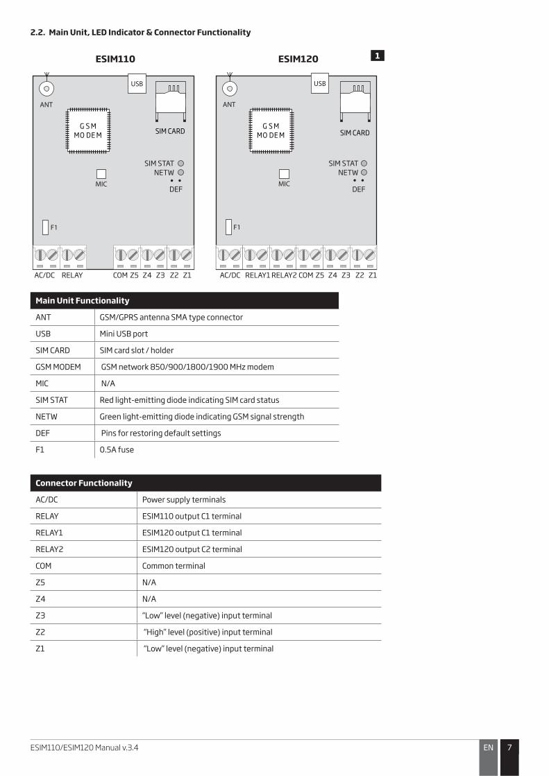
2.2. Main Unit, LED Indicator & Connector Functionality
ANT
MIC
AC/DC RELAY COM
ESIM110 ESIM120
DEF
Z5 Z4 Z3 Z2 Z1 AC/DC RELAY1 RELAY2 COM Z5 Z4 Z3 Z2 Z1
USB
F1
ANT
MIC
USB
F1
SIM CARDSIM CARDG S M
MO DE M
G S M
MO DE M
SIM STAT
NETW
SIM STAT
NETW
DEF
Main Unit Functionality
ANT GSM/GPRS antenna SMA type connector
USB Mini USB port
SIM CARD SIM card slot / holder
GSM MODEM GSM network 850/900/1800/1900 MHz modem
MIC N/A
SIM STAT Red light-emitting diode indicating SIM card status
NETW Green light-emitting diode indicating GSM signal strength
DEF Pins for restoring default settings
F1 0.5A fuse
Connector Functionality
AC/DC Power supply terminals
RELAY ESIM110 output C1 terminal
RELAY1 ESIM120 output C1 terminal
RELAY2 ESIM120 output C2 terminal
COM Common terminal
Z5 N/A
Z4 N/A
Z3 “Low” level (negative) input terminal
Z2 “High” level (positive) input terminal
Z1 “Low” level (negative) input terminal
1
88 EN ESIM110/ESIM120 Manual v.3.4
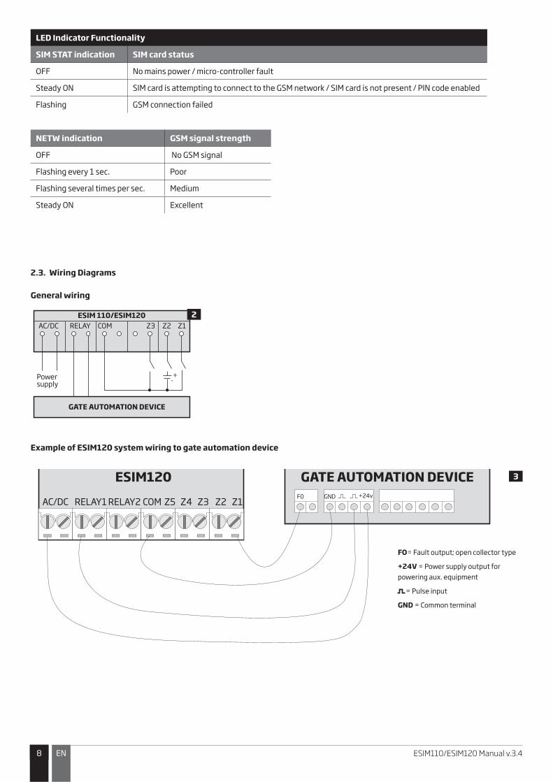
LED Indicator Functionality
SIM STAT indication SIM card status
OFF No mains power / micro-controller fault
Steady ON SIM card is attempting to connect to the GSM network / SIM card is not present / PIN code enabled
Flashing GSM connection failed
NETW indication GSM signal strength
OFF No GSM signal
Flashing every 1 sec. Poor
Flashing several times per sec. Medium
Steady ON Excellent
2.3. Wiring Diagrams
General wiring
ESIM 110/ESIM120AC/DC
Powersupply
GATE AUTOMATION DEVICE
+-
RELAY COM Z3 Z2 Z1
Example of ESIM120 system wiring to gate automation device
ESIM120 GATE AUTOMATION DEVICE
AC/DC RELAY1 RELAY2 COM Z5 Z4 Z3 Z2 Z1F0 +24v
FO= Fault output; open collector type
+24V = Power supply output for
powering aux. equipment
= Pulse input
GND = Common terminal
GND
3
2

99ENESIM110/ESIM120 Manual v.3.4
3. INSTALLATION• The system should be installed indoors, in stationary environment ONLY.
• For the connection of input/output terminals, use 0.50 mm2 1 thread unshielded cable of up to 100 meters length.
1. Wire up the system in accordance with the wiring diagrams (see 2.3 Wiring Diagrams for more details).
2. Connect the GSM/GPRS antenna. Based on the type of the GSM/GPRS antenna supplied with ESIM110/ESIM120 unit, follow the recom-mendations for the antenna installation:
GSM/GPRS antenna
4
Never install in the following locations:
• inside the metal cabinet
• close to the metal surface and/ or power lines
3. Disable the PIN code request of the SIM card by inserting it into a mobile phone and following the proper menu steps.
4. Once the PIN code is disabled, insert the SIM card into the SIM card slot / holder of ESIM110/ESIM120 system.
5
6
5. Power up the system and wait until indicator SIM STAT lights up indicating SIM card status.
6. Once the indicator SIM STAT lights OFF, the illuminated indicator NETW lights up indicating that the system has successfully connected to the GSM network. To find the strongest GSM signal, position the GSM/GPRS antenna and follow the indications provided by NETW indicator (see 2.2. Main Unit, LED Indicator & Connector Functionality for more details).
7. Change the system language if necessary (see 6. SYSTEM LANGUAGE for more details).
8. Change the default SMS password (see 7. SMS PASSWORD for more details).
9. Set the phone number for Admin 1 (see 8. ADMINISTRATOR PHONE NUMBERS for more details).
10. Set system date and time (see 9. DATE AND TIME for more details).
11. Once the system is fully configured, it is ready for use. However, if you fail to receive a reply by SMS text message from the system, please check the SMSC (Short Message Service Center) phone number. For more details regarding the SMS center phone number, please refer to 17. SMSC (Short Message Service Center) Phone Number.
ATTENTION: The system is NOT compatible with pure 3G SIM cards. Only 2G/GSM SIM cards and 3G SIM cards with 2G/GSM profile enabled are supported. For more details, please contact your GSM operator.
ATTENTION: We also recommend you to disable call forwarding, voice mail/text message reports on missed/busy calls and similar services that might cause incorrect system operation. Please contact your GSM operator for more details on these services and how to disable them.
NOTE: For maximum system reliability we recommend you do NOT use a Pay As You Go SIM card. Otherwise, in the event of insufficient credit balance on the SIM card, the system would fail to make a phone call or send SMS text messages.
NOTE: We advise you to choose the same GSM SIM provider for your system as for your mobile phone. This will ensure the fastest, most reliable SMS text message delivery service and phone call connection.
NOTE: Even though the installation process of ESIM110/ESIM120 is not too complicated, we still recommend to perform it by a person with basic knowledge in electrical engineering and electronics to avoid any system damage.
1010 EN ESIM110/ESIM120 Manual v.3.4
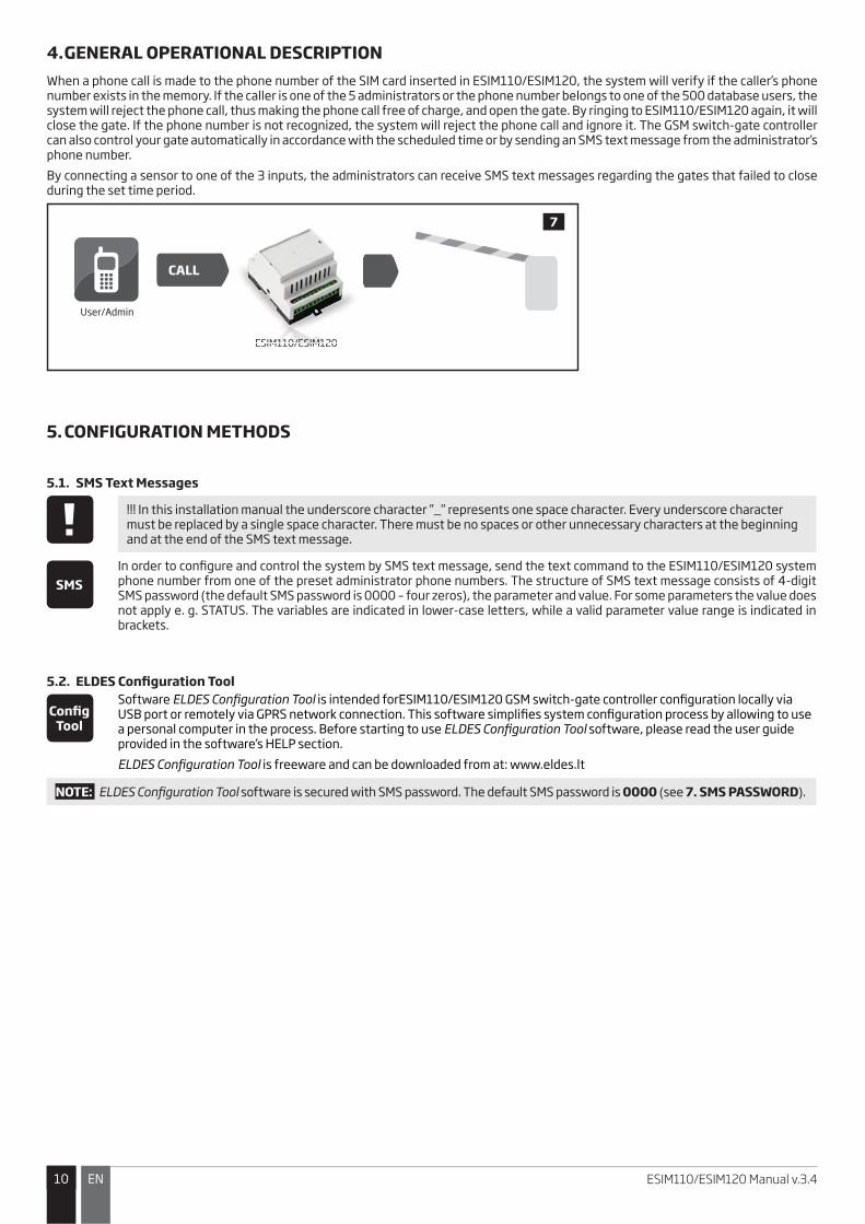
4. GENERAL OPERATIONAL DESCRIPTIONWhen a phone call is made to the phone number of the SIM card inserted in ESIM110/ESIM120, the system will verify if the caller’s phone number exists in the memory. If the caller is one of the 5 administrators or the phone number belongs to one of the 500 database users, the system will reject the phone call, thus making the phone call free of charge, and open the gate. By ringing to ESIM110/ESIM120 again, it will close the gate. If the phone number is not recognized, the system will reject the phone call and ignore it. The GSM switch-gate controller can also control your gate automatically in accordance with the scheduled time or by sending an SMS text message from the administrator’s phone number.
By connecting a sensor to one of the 3 inputs, the administrators can receive SMS text messages regarding the gates that failed to close during the set time period.
User/Admin
ESIM110/ESIM120
CALL
7
ESIM1M11110//E0/ESIMM12120
5. CONFIGURATION METHODS
5.1. SMS Text Messages
!!! In this installation manual the underscore character ”_” represents one space character. Every underscore character must be replaced by a single space character. There must be no spaces or other unnecessary characters at the beginning and at the end of the SMS text message.
SMSIn order to configure and control the system by SMS text message, send the text command to the ESIM110/ESIM120 system phone number from one of the preset administrator phone numbers. The structure of SMS text message consists of 4-digit SMS password (the default SMS password is 0000 – four zeros), the parameter and value. For some parameters the value does not apply e. g. STATUS. The variables are indicated in lower-case letters, while a valid parameter value range is indicated in brackets.
5.2. ELDES Configuration Tool
Config Tool
Software ELDES Configuration Tool is intended forESIM110/ESIM120 GSM switch-gate controller configuration locally via USB port or remotely via GPRS network connection. This software simplifies system configuration process by allowing to use a personal computer in the process. Before starting to use ELDES Configuration Tool software, please read the user guide provided in the software’s HELP section.
ELDES Configuration Tool is freeware and can be downloaded from at: www.eldes.lt
NOTE: ELDES Configuration Tool software is secured with SMS password. The default SMS password is 0000 (see 7. SMS PASSWORD).
1111ENESIM110/ESIM120 Manual v.3.4
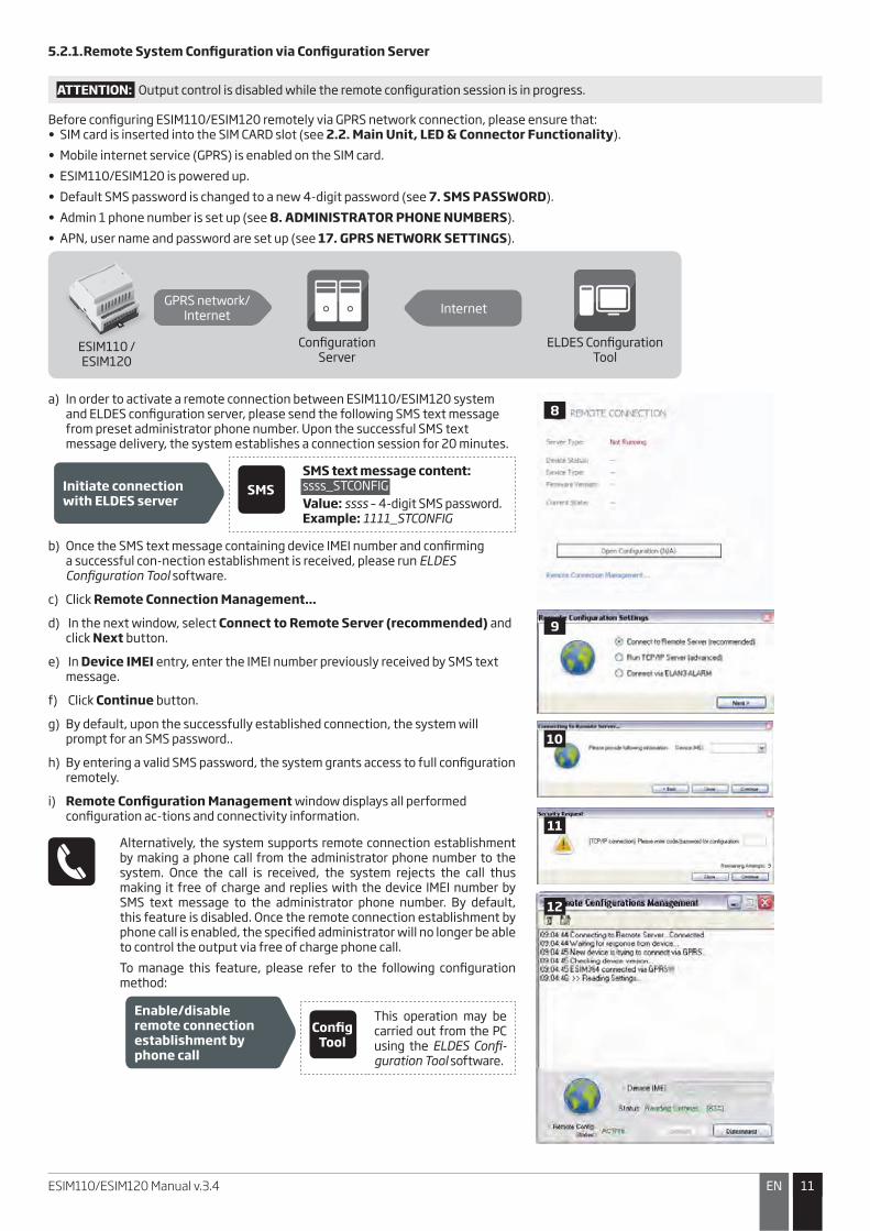
5.2.1. Remote System Configuration via Configuration Server
ATTENTION: Output control is disabled while the remote configuration session is in progress.
Before configuring ESIM110/ESIM120 remotely via GPRS network connection, please ensure that: • SIM card is inserted into the SIM CARD slot (see 2.2. Main Unit, LED & Connector Functionality).
• Mobile internet service (GPRS) is enabled on the SIM card.
• ESIM110/ESIM120 is powered up.
• Default SMS password is changed to a new 4-digit password (see 7. SMS PASSWORD).
• Admin 1 phone number is set up (see 8. ADMINISTRATOR PHONE NUMBERS).
• APN, user name and password are set up (see 17. GPRS NETWORK SETTINGS).
ESIM110 /ESIM120
Configuration Server
ELDES Configuration Tool
GPRS network/Internet
Internet
ESIM110 /
a) In order to activate a remote connection between ESIM110/ESIM120 system and ELDES configuration server, please send the following SMS text message from preset administrator phone number. Upon the successful SMS text message delivery, the system establishes a connection session for 20 minutes.
Initiate connection with ELDES server
SMSSMS text message content: ssss_STCONFIG
Value: ssss – 4-digit SMS password. Example: 1111_STCONFIG
b) Once the SMS text message containing device IMEI number and confirming a successful con-nection establishment is received, please run ELDES Configuration Tool software.
c) Click Remote Connection Management...
d) In the next window, select Connect to Remote Server (recommended) and click Next button.
e) In Device IMEI entry, enter the IMEI number previously received by SMS text message.
f) Click Continue button.
g) By default, upon the successfully established connection, the system will prompt for an SMS password..
h) By entering a valid SMS password, the system grants access to full configuration remotely.
i) Remote Configuration Management window displays all performed configuration ac-tions and connectivity information.
Alternatively, the system supports remote connection establishment by making a phone call from the administrator phone number to the system. Once the call is received, the system rejects the call thus making it free of charge and replies with the device IMEI number by SMS text message to the administrator phone number. By default, this feature is disabled. Once the remote connection establishment by phone call is enabled, the specified administrator will no longer be able to control the output via free of charge phone call.
To manage this feature, please refer to the following configuration method:
Enable/disable remote connection establishment by phone call
Config Tool
This operation may be carried out from the PC using the ELDES Confi-guration Tool software.
8
9
10
11
12

1212 EN ESIM110/ESIM120 Manual v.3.4
5.2.2. Remote System Configuration via Direct Connection
ATTENTION: Output control is disabled while the remote configuration session is in progress.
Before configuring ESIM110/ESIM120 remotely via GPRS network connection, please ensure that:
• SIM card is inserted into the SIM CARD slot (see 2.2. Main Unit, LED & Connector Functionality).
• Mobile internet service (GPRS) is enabled on the SIM card.
• ESIM110/ESIM120 is powered up.
• Default SMS password is changed to a new 4-digit password (see 7. SMS PASSWORD).
• Admin 1 phone number is set up (see 8. ADMINISTRATOR PHONE NUMBERS).
• APN, user name and password are set up (see 17. GPRS NETWORK SETTINGS).
• Machine running ELDES Configuration Tool software provides access via public IP address.
• TCP port 5000 is forwarded for the IP address of the machine running ELDES Configuration Tool software.
ESIM110 /ESIM120
ELDES Configuration Tool
GPRS network/Internet
ESIM110 /
a) Run ELDES Configuration Tool software. b) Click Remote Connection Management... c) In the next window, select Run TCP/IP Server (advanced) and click Next button.d) Set a TCP port for listening for incoming connections or leave the default TCP port 5000. e) Click Continue button. f) In order to activate a remote connection between ESIM110/ESIM120 system and ELDES
Configuration Tool software running as remote configuration server, please send the following SMS text message from preset administrator phone number. Upon the successful SMS text message delivery, the system establishes a connection session for 20 minutes.
Initiate connection with ELDES Configuration Tool
SMSSMS text message content: ssss_STCONFIG:add.add.add.add:pprrt or
ssss_STCONFIG:host-name:pprrt
Value: ssss – 4-digit SMS password; add.add.add. add – public IP address of the machine running ELDES Configuration Tool software; pprrt – TCP port number, range – [1... 65535]; host-name – public host-name of the machine running ELDES Configuration Tool software. Example: 1111_STCONFIG:62.80.115.102:4522
g) By default, upon the successfully established connection, the system will prompt for an SMS password.
h) By entering a valid SMS password, the system grants access to full configuration remotely. i) Remote Configuration Management window displays all performed configuration ac-
tions and connectivity information.
13
14
15
16
17

1313ENESIM110/ESIM120 Manual v.3.4
5.2.3. Ending the Configuration Process
After the system configuration is complete, use one of the following methods to end the configuration process:
�� Click Disconnect or Stop button and close ELDES Configuration Tool software;
�� The session will automatically expire in 20 minutes. Before the last 5 minutes, the software will offer the user to extend the session for another 20 minutes.
�� Alternatively, the connection with the server can be terminated at any time by sending an SMS text message.
Terminate the connection
SMS text message content: ssss_ENDCONFIG
Value: ssss – 4-digit SMS password.
Example: 1111_ENDCONFIG
Once the session is expired or terminated, the system will reply with an SMS text message confirming the end of the session.
1414 EN ESIM110/ESIM120 Manual v.3.4
6. SYSTEM LANGUAGE
The system comes equipped with a multiple languages for communication with the administrator by SMS text messages. The default system language depends on the firmware, which is based on the customer’s location.
List of currently available system languages:�� English
�� Estonian
�� German
�� Lithuanian
�� French
�� Slovak
Set system language SMSSMS text message content:LN
Value: LN – language index; range – [EN – English, EE – Estonian, DE – German, LT – Lithua-nian, FR – French, SK – Slovak].Example: LT
Config Tool This operation may be carried out from the PC using the ELDES Configuration Tool software.
NOTE: To change the language once the system has already been configured, you need to reset the device to the default configura-tion. For more details on how to do this, please refer to 20.2. Restoring Default Parameters.
7. SMS PASSWORDFor security reasons, the system uses the following type of password:
• SMS password – 4-digit password used for system configuration and control from administrator phone number by SMS text messages and logging in to ELDES Configuration Tool software . By default, SMS password is 0000, which MUST be changed!
Set SMS password SMSSMS text message content:wwww_PSW_ssss
Value: wwww – 4-digit default SMS password; ssss – 4-digit new SMS password; range – [0001... 9999]. Example: 0000_PSW_1111
Config Tool This operation may be carried out from the PC using the ELDES Configuration Tool software.
NOTE: The system rejects the SMS text messages containing wrong SMS password even from a preset administrator phone number.
1515ENESIM110/ESIM120 Manual v.3.4
8. ADMINISTRATOR PHONE NUMBERSThe system supports up to 5 administrator phone numbers identified as Admin 1 through 5. When the phone number is set, the administrator will be able to configure and control the system by SMS text messages as well as by free of charge phone call and receive the input alarm SMS text messages from the system (see 14.1. Input Names and Alarm Notification). ESIM120 allows to assign output C1, output C2 or both outputs (simultaneous control) to a certain administrator.
By default, the system ignores any incoming calls and SMS text messages from a non-preset phone number as well as it rejects the SMS text messages containing wrong SMS password even from a preset administrator phone number. For more details on how to enable output control from a non-preset phone number, please refer to 11.5. Output Control from any Phone Number.
To set Admin 1 phone number is mandatory, while the other 4 are optional. The supported phone number format is the following:
�� International (w/o plus) – The phone numbers must be entered starting with an international country code in the following format: [international code][area code][local number], example for UK: 4417091111111.
Set administrator phone number
SMSSMS text message content:ssss_NRas:ttteeellnnuumm
Value: ssss – 4-digit SMS password; as – administrator phone number slot, range – [1... 5]; ttteeellnnuumm – up to 15 digits administrator phone number. Example: 1111_NR1:4417091111111
Config Tool This operation may be carried out from the PC using the ELDES Configuration Tool software.
View administrator phone numbers
SMSSMS text message content:ssss_HELPNR
Value: ssss – 4-digit SMS password. Example: 1111_HELPNR
Config Tool This operation may be carried out from the PC using the ELDES Configuration Tool software.
Assign output (-s) to individual administrator
ONLY FOR ESIM120
Config Tool
This operation may be carried out from the PC using the ELDES Configuration Tool software.
Delete administrator phone number
SMSSMS text message content:ssss_NRas:DEL
Value: ssss – 4-digit SMS password; as – administrator phone number slot, range – [2... 5]. Example: 1111_NR2:DEL
Config Tool This operation may be carried out from the PC using the ELDES Configuration Tool software.
ATTENTION: NEVER set a phone number of the device’s SIM card as an administrator phone number!
ATTENTION: Once Admin 1 phone number is set, the system will restrict only to modify it
ATTENTION: Multiple administrator phone numbers can be set by a single SMS text message, Example: 1111_NR1:4417091111111_ NR5:4417091111112_NR2:4417091111113_NR3: 4417091111114
NOTE: Multiple administrator phone numbers can be deleted by a single SMS text message, Example: 1111_NR2:DEL_NR4:DEL_NR3:DEL
NOTE FOR ESIM120: The administrator can control any output by SMS text message regardless of the output assigned to the admin-istrator phone number (see 11.3. Output Control by SMS Text Message).
For more details on output control, please refer to 11. OUTPUT (-S).
1616 EN ESIM110/ESIM120 Manual v.3.4
9. DATE AND TIMEThe system comes equipped with internal real-time clock (RTC) that keeps track of the current date and time. Once the system is up and running, the user must set the correct date and time, otherwise the system will not operate properly. By default, after shutting down and starting up the system, the date and time must be set again. In order to avoid manual date and time set up, please use the automatic date and time synchronization feature (see 9.1. Automatic Date and Time Synchronization).
Set date and time SMSSMS text message content:ssss_yyyy.mm.dd_hr:mn
Value: ssss – 4-digit SMS password; yyyy – year; mm – month, range – [01... 12]; dd – day, range – [01... 31]; hr – hours, range – [00... 23]; mn – minutes, range – [00... 59].
Example: 1111_2013.03.16_14:33
Config Tool This operation may be carried out from the PC using the ELDES Configuration Tool software.
9.1. Automatic Date and Time Synchronization
This feature enables the system to set the date and time automatically without the user being involved in this process. The system supports the following methods of automatic date and time synchronization that are used automatically on system start-up and periodically (by default – every 30 days):
�� Via GSM network – Once enabled, the system automatically sends a date/time request to the GSM operator. This method is the most accurate synchronization method. Some GSM operators might not support it.
�� By SMS text message – Once enabled, the system automatically sends the SMS text message to its own phone number and retrieves the date and time from the SMS text message reply, as the included date and time is set by the SMSC (SMS center). This method is not as accurate as the synchronization via GSM network, but always effective.
By default, synchronization via GSM network is disabled. To enable/disable automatic date and time synchronization via GSM network, please refer to the following configuration methods.
Enable/disable synchronization via GSM network
Config Tool This operation may be carried out from the PC using the ELDES Configuration Tool software.
By default, synchronization by SMS text message is disabled. To enable/disable automatic date and time synchronization by SMS text message, please enter/remove device phone number using one of the following configuration methods.
Enter/remove device phone number for synchronization by SMS text message
Config Tool This operation may be carried out from the PC using the ELDES Configuration Tool software.
By default, the date and time synchronization period is 30 days. To set a different period, please refer to the following configuration methods.
Set synchronization period
Config Tool This operation may be carried out from the PC using the ELDES Configuration Tool software.
NOTE: When setting up automatic date and time synchronization feature remotely, you may wish to restart the system when done. For more details, please refer to 19. REMOTE SYSTEM RESTART.
NOTE: 0 value disables periodic date and time synchronization.
NOTE: When both synchronization methods are enabled, the system will always attempt to synchronize date and time via GSM net-work every time the system shuts down and starts up again and in accordance with the set period value. In the event of first method’s failure, the system will attempt to use the SMS text message method as a backup.

1717ENESIM110/ESIM120 Manual v.3.4
10. USER PHONE NUMBER DATABASEThe system comes equipped with a user database of 500 user capacity. When the phone number is set, the user will be able to control the output (-s) by free of charge phone call. ESIM120 user database allows to assign output C1, output C2 or both outputs (simultaneous control) to a certain user. The supported phone number format is the following:
�� International (w/o plus) – The phone numbers must be entered starting with an international country code in the following format: [international code][area code][local number], example for UK: 4417091111111.
ESIM110/ESIM120 user database supports user validity and access restriction features. For more details, please refer to 10.1. User Validity and Access Restriction.
Optionally, a user name can be set that typically specifies the owner’s name of a certain phone number, for example: John.
The phone number and user name (if any) are used when searching for a certain user in the database as well as they are automatically added in the event log after the successful output control event (see 13. EVENT LOG).
Add user phone number (and user name)
SMSSMS text message content:ssss_N:ttteeellnnuumm or ssss_N:ttteeellnnuumm:user-name
Value: ssss – 4-digit SMS password; ttteeellnnuumm – up to 15 digits user phone number; user-name – up to 16 characters user name.
Example: 1111_N:4417091111111:John
Config Tool This operation may be carried out from the PC using the ELDES Configuration Tool software.
View user phone numbers
SMSSMS text message content:ssss_GETALLNUMBERS
Value: ssss – 4-digit SMS password. Example: 1111_GETALLNUMBERS
Config Tool This operation may be carried out from the PC using the ELDES Configuration Tool software.
Search for user by phone number or name
SMSSMS text message content:ssss_T:ttteeellnnuumm or ssss_T:user-name
Value: ssss – 4-digit SMS password; ttteeellnnuumm – up to 15 digits user phone number; user-name – up to 16 characters user name.
Example: 1111_T:John
Config Tool This operation may be carried out from the PC using the ELDES Configuration Tool software.
Assign output (-s) to individual user
ONLY FOR ESIM120
SMSSMS text message content:ssss_OUTPUT_ttteeellnnuumm_o or ssss_OUTPUT_user-name_o
Value: ssss – 4-digit SMS password; ttteeellnnuumm – up to 15 digits user phone number; o – output number; range [1 – output C1; 2 – output C2; 3 – both outputs]; user-name – up to 16 characters user name.Example: 1111_OUTPUT_4417091111111_2
Config Tool This operation may be carried out from the PC using the ELDES Configuration Tool software.

1818 EN ESIM110/ESIM120 Manual v.3.4
Delete individual user SMSSMS text message content:ssss_D:ttteeellnnuumm or ssss_D:user-name
Value: ssss – 4-digit SMS password; ttteeellnnuumm – up to 15 digits user phone number; user-name – up to 16 characters user name.
Example: 1111_D:John
Config Tool This operation may be carried out from the PC using the ELDES Configuration Tool software.
Delete all users SMSSMS text message content:ssss_D:ALL
Value: ssss – 4-digit SMS password.
Example: 1111_D:ALL
Config Tool This operation may be carried out from the PC using the ELDES Configuration Tool software.
The user database can be exported/imported to/from a .csv file for backup purposes or for a convenient user database management. To export/import an existing user database, please refer to the following configuration method.
Export/import existing user database from/to file
Config Tool This operation may be carried out from the PC using the ELDES Configuration Tool software.
By default, the user database is enabled and output control by all database users is permitted. To deny output control instead of deleting all users from the database, please disable the user database using one of the following configuration methods.
Disable user database SMSSMS text message content:ssss_DBM_OFF
Value: ssss – 4-digit SMS password.
Example: 1111_DBM_OFF
Config Tool This operation may be carried out from the PC using the ELDES Configuration Tool software.
To enable user database, please refer to the following configuration methods.
Enable user database SMSSMS text message content:ssss_DBM_ON
Value: ssss – 4-digit SMS password.
Example: 1111_DBM_ON
Config Tool This operation may be carried out from the PC using the ELDES Configuration Tool software.
ATTENTION: Space and colon characters are NOT allowed in the user names.
NOTE: Multiple users can be added by a single SMS text message, Example: 1111_N:4417091111111:John_ 4417091111112:_ 4417091111113:Tom
NOTE: Multiple users can be deleted by a single SMS text message, Example: 1111_D:John_ 4417091111113_Mark
For more details on output control, please refer to 11. OUTPUT (-S).

1919ENESIM110/ESIM120 Manual v.3.4
10.1. User Validity and Access Restriction
The system allows to restrict access in accordance with the scheduler assigned to a certain user. When one or more schedulers are assigned, the user will be able to control the output only on the specified weekdays and time set up in the scheduler. The system allows to assign up to 8 different schedulers. For more details on how to set up the schedulers, please refer to 12. SCHEDULERS.
In addition, the system allows to limit the user validity by the following methods:
�� Deadline (valid until) – When a specified date and time hits, the user will be automatically deleted from the database.
�� Ring counter – When a specified number of phone calls to the system expires, the user will be automatically deleted from the database.
Assign scheduler to individual user
SMSSMS text message content:ssss_NSCHED_ttteeellnnuumm_c:ON or ssss_NSCHED_user-name_c:ON
Value: ssss – 4-digit SMS password; ttteeellnnuumm – up to 15 digits user phone number; c – scheduler number; range – [1... 8]; user-name – up to 16 characters user name.
Example: 1111_NSCHED_John_5:ON
Config Tool This operation may be carried out from the PC using the ELDES Configuration Tool software.
Remove scheduler from individual user
SMSSMS text message content:ssss_NSCHED_ttteeellnnuumm_c:OFF or ssss_NSCHED_user-name_c:OFF
Value: ssss – 4-digit SMS password; ttteeellnnuumm – up to 15 digits user phone number; c – scheduler number; range – [1... 8]; user-name – up to 16 characters user name.
Example: 1111_NSCHED_John_5:OFF
Config Tool This operation may be carried out from the PC using the ELDES Configuration Tool software.
Set deadline for individual user
SMSSMS text message content: ssss_EXPIRYTIME_ttteeellnnuumm_yyyy.mm.dd_hr:mn or ssss_EXPIRYTIME_user-name_yyyy.mm.dd_hr:mn
Value: ssss – 4-digit SMS password; ttteeellnnuumm – up to 15 digits user phone number; yyyy – year; mm – month, range – [01... 12]; dd – day, range – [01... 31]; hr – hours, range – [00... 23]; mn – minutes, range – [00... 59]; user-name – up to 16 characters user name.
Example: 1111_EXPIRYTIME_John_2015.06.29_19:35
Extend deadline for individual user
SMSSMS text message content: ssss_EXPIRYTIME_ttteeellnnuumm_extendmins or ssss_EXPIRYTIME_user-name_extendmins
Value: ssss – 4-digit SMS password; ttteeellnnuumm – up to 15 digits user phone number; extendmins – time period, range – [1... 2147483648] minutes; user-name – up to 16 characters user name.Example: 1111_EXPIRYTIME_John_2350
Config Tool This operation may be carried out from the PC using the ELDES Configuration Tool software.
Remove deadline from individual user
SMSSMS text message content: ssss_EXPIRYTIME_ttteeellnnuumm_0 or ssss_EXPIRYTIME_user-name_0
Value: ssss – 4-digit SMS password; ttteeellnnuumm – up to 15 digits user phone number; user-name – up to 16 characters user name.Example: 1111_EXPIRYTIME_4417091111111_0
Config Tool This operation may be carried out from the PC using the ELDES Configuration Tool software.

2020 EN ESIM110/ESIM120 Manual v.3.4
View set up deadline for individual user
SMSSMS text message content:ssss_EXPIRYTIME_ttteeellnnuumm_? or ssss_EXPIRYTIME_user-name_?
Value: ssss – 4-digit SMS password; ttteeellnnuumm – up to 15 digits user phone number; user-name – up to 16 characters user name.
Example: 1111_EXPIRYTIME_4417091111111_?
Set ring counter for individual user
SMSSMS text message content:ssss_RCOUNT_ttteeellnnuumm_numofcalls or ssss_RCOUNT_user-name_numofcalls
Value: ssss – 4-digit SMS password; ttteeellnnuumm – up to 15 digits administrator phone number; user-name – up to 16 characters user name; numofcalls – number of phone calls, range – [0... 4294967296].
Example: 1111_RCOUNT_4417091111111_152
Config Tool This operation may be carried out from the PC using the ELDES Configuration Tool software.
View set up ring counter value for individual user
SMSSMS text message content:ssss_RCOUNT_ttteeellnnuumm_? or ssss_RCOUNT_user-name_?
Value: ssss – 4-digit SMS password; ttteeellnnuumm – up to 15 digits administrator phone number; user-name – up to 16 characters user name.
Example: 1111_RCOUNT_John_?
Config Tool This operation may be carried out from the PC using the ELDES Configuration Tool software.
ATTENTION: If the date and time are not set, the system will NOT be able to manage user validity and access. For more details on how to set date and time, please refer to 9. DATE AND TIME.
NOTE: Multiple schedulers can be assigned/removed by a single SMS text message, Example: 1111_NSCHED_John_2:ON_6:OFF_3:OFF_5:ON
NOTE: 0 value removes the set up deadline from the user.
NOTE: 0 value removes the set up ring counter from the user.

2121ENESIM110/ESIM120 Manual v.3.4
11. OUTPUT (-S)ESIM110 comes equipped with 1 built-in output, while ESIM120 – with 2 outputs. The output (-s) is intended for connection and control of the gate automation device by the following methods:
�� Free of charge phone call from the user or administrator phone number (see 11.2. Output Control by Free of Charge Phone Call).�� SMS text message from the administrator phone number (see 11.3. Output Control by SMS Text Message).�� Automatically in accordance with the scheduled weekdays and time (see 11.6. Automatic Output Control).
To set an output type, please refer to the following configuration method.
Set output as NO (normally-open) or NC (normally-closed)
Config Tool This operation may be carried out from the PC using the ELDES Configuration Tool software.
The system allows to view the current output state by the following configuration method.
View output state SMSSMS text message content:ssss_STATUS
Value: ssss – 4-digit SMS password.
Example: 1111_STATUS
ATTENTION: Once the scheduler, set up for automatic output control comes into effect, the user/administrator will NOT be able to control the output by phone call and SMS text message (see 11.6. Automatic Output Control).
11.1. Output Name (-s)
The output (-s) has a name that can be customized. Typically, the name specifies a device type connected to a determined output, for example: Gate. The name can be used instead of output number when controlling the output by SMS text message.
By default, the output names are: C1 – Controll1 (ESIM110, ESIM120), C2 – Controll2 (ESIM120).
Set output name
ONLY FOR ESIM110
SMSSMS text message content:ssss_C1:out-name
Value: ssss – 4-digit SMS password; out-name – up to 16 characters output name.
Example: 1111_C1:OFF:00.10.15
Config Tool This operation may be carried out from the PC using the ELDES Configuration Tool software.
Set output name
ONLY FOR ESIM120
SMSSMS text message content:ssss_Co:out-name
Value: ssss – 4-digit SMS password; o – output number, range [1 – output C1; 2 – output C2]; out-name – up to 16 characters output name.
Example: 1111_C1:OFF:00.10.15
Config Tool This operation may be carried out from the PC using the ELDES Configuration Tool software.
View output name SMSSMS text message content:ssss_STATUS
Value: ssss – 4-digit SMS password.
Example: 1111_STATUS
Config Tool This operation may be carried out from the PC using the ELDES Configuration Tool software.

2222 EN ESIM110/ESIM120 Manual v.3.4
ATTENTION: Space, colon, semi-colon characters, parameter names and/or values, such as PSW, STATUS, ON, OFF etc. are NOT allowed in output names.
11.2. Output Control by Free of Charge Phone Call
To open or close the gate, dial the system’s phone number from any available user or administrator phone numbers (see 10. USER PHONE NUMBER DATABASE and 8. ADMINISTRATOR PHONE NUMBERS for phone number management). The phone call is free charge as the system rejects it and turns ON/OFF the output (-s) for the preset time period (pulse; by default – 2 seconds) resulting in the gate opening or closing, depending on the current gate state and selected output type NO or NC. If there is more than one preset caller dialing to the system at the same time, the system will accept the incoming call from the caller who was the first to dial while other caller (-s) will be ignored.
The system supports a confirmation phone call to user/administrator phone number. For more details, please refer to 11.4. Output Control Confirmation by Call Back
Set output pulse duration
SMSSMS text message content:ssss_TIMER1:pl
Value: ssss – 4-digit SMS password; pl – pulse duration, range – [1... 10] seconds.
Example: 1111_TIMER1:8
Config Tool This operation may be carried out from the PC using the ELDES Configuration Tool software.
Set output pulse duration
ONLY FOR ESIM120
SMSSMS text message content:ssss_TIMERo:pl
Value: ssss – 4-digit SMS password; o – output number, range [1 – output C1; 2 – output C2]; pl – pulse duration, range – [1... 10] seconds.
Example: 1111_TIMER2:4
Config Tool This operation may be carried out from the PC using the ELDES Configuration Tool software.
NOTE: ELDES Configuration Tool software allows to set the unlimited output pulse duration value.
11.3. Output Control by SMS Text Message
To open or close the gate, send the SMS text message from any of 5 available administrator phone numbers (see 8. USER PHONE NUMBER DATABASE for phone number management). The system will turn ON the output (-s) for a determined time period (pulse) resulting in the gate opening or closing, depending on the current gate state. The confirmation reply by SMS text message, containing the output name (see 11.1. Output Name (-s)), will be sent to the administrator phone number that the output control by SMS text message was initiated from.
Turn ON outputfor time period
ONLY FOR ESIM110
SMSSMS text message content:ssss_C1:ON:hr.mn.sc or ssss_out-name:ON:hr.mn.scv
Value: ssss – 4-digit SMS password; hr – hours, range – [00... 23]; mn – minutes, range – [00... 59]; sc – seconds, range – [00... 59]; out-name – up to 16 characters output name.
Example: 1111_Gate:ON:00.00.02
Config Tool This operation may be carried out from the PC using the ELDES Configuration Tool software.
2323ENESIM110/ESIM120 Manual v.3.4
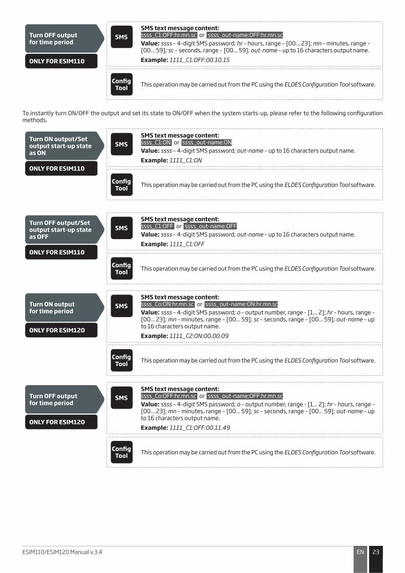
Turn OFF outputfor time period
ONLY FOR ESIM110
SMSSMS text message content:ssss_C1:OFF:hr.mn.sc or ssss_out-name:OFF:hr.mn.sc
Value: ssss – 4-digit SMS password; hr – hours, range – [00... 23]; mn – minutes, range – [00... 59]; sc – seconds, range – [00... 59]; out-name – up to 16 characters output name.
Example: 1111_C1:OFF:00.10.15
Config Tool This operation may be carried out from the PC using the ELDES Configuration Tool software.
To instantly turn ON/OFF the output and set its state to ON/OFF when the system starts-up, please refer to the following configuration methods.
Turn ON output/Set output start-up state as ON
ONLY FOR ESIM110
SMSSMS text message content:ssss_C1:ON or ssss_out-name:ON
Value: ssss – 4-digit SMS password; out-name – up to 16 characters output name.
Example: 1111_C1:ON
Config Tool This operation may be carried out from the PC using the ELDES Configuration Tool software.
Turn OFF output/Set output start-up state as OFF
ONLY FOR ESIM110
SMSSMS text message content:ssss_C1:OFF or ssss_out-name:OFF
Value: ssss – 4-digit SMS password; out-name – up to 16 characters output name.
Example: 1111_C1:OFF
Config Tool This operation may be carried out from the PC using the ELDES Configuration Tool software.
Turn ON outputfor time period
ONLY FOR ESIM120
SMSSMS text message content:ssss_Co:ON:hr.mn.sc or ssss_out-name:ON:hr.mn.sc
Value: ssss – 4-digit SMS password; o – output number, range - [1... 2]; hr – hours, range – [00... 23]; mn – minutes, range – [00... 59]; sc – seconds, range – [00... 59]; out-name – up to 16 characters output name.
Example: 1111_C2:ON:00.00.09
Config Tool This operation may be carried out from the PC using the ELDES Configuration Tool software.
Turn OFF outputfor time period
ONLY FOR ESIM120
SMSSMS text message content:ssss_Co:OFF:hr.mn.sc or ssss_out-name:OFF:hr.mn.sc
Value: ssss – 4-digit SMS password; o – output number, range - [1... 2]; hr – hours, range – [00... 23]; mn – minutes, range – [00... 59]; sc – seconds, range – [00... 59]; out-name – up to 16 characters output name.
Example: 1111_C1:OFF:00.11.49
Config Tool This operation may be carried out from the PC using the ELDES Configuration Tool software.
2424 EN ESIM110/ESIM120 Manual v.3.4
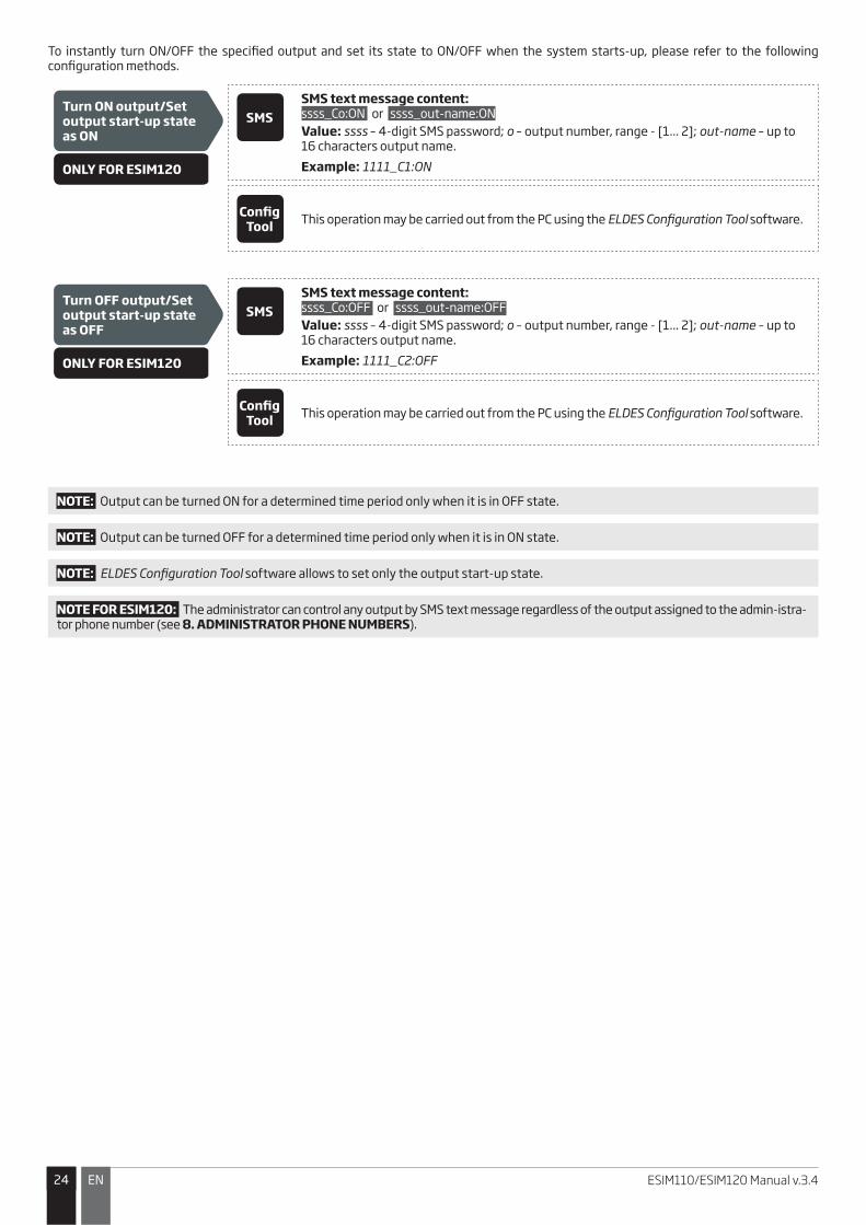
To instantly turn ON/OFF the specified output and set its state to ON/OFF when the system starts-up, please refer to the following configuration methods.
Turn ON output/Set output start-up state as ON
ONLY FOR ESIM120
SMSSMS text message content:ssss_Co:ON or ssss_out-name:ON
Value: ssss – 4-digit SMS password; o – output number, range - [1... 2]; out-name – up to 16 characters output name.
Example: 1111_C1:ON
Config Tool This operation may be carried out from the PC using the ELDES Configuration Tool software.
Turn OFF output/Set output start-up state as OFF
ONLY FOR ESIM120
SMSSMS text message content:ssss_Co:OFF or ssss_out-name:OFF
Value: ssss – 4-digit SMS password; o – output number, range - [1... 2]; out-name – up to 16 characters output name.
Example: 1111_C2:OFF
Config Tool This operation may be carried out from the PC using the ELDES Configuration Tool software.
NOTE: Output can be turned ON for a determined time period only when it is in OFF state.
NOTE: Output can be turned OFF for a determined time period only when it is in ON state.
NOTE: ELDES Configuration Tool software allows to set only the output start-up state.
NOTE FOR ESIM120: The administrator can control any output by SMS text message regardless of the output assigned to the admin-istra-tor phone number (see 8. ADMINISTRATOR PHONE NUMBERS).
2525ENESIM110/ESIM120 Manual v.3.4
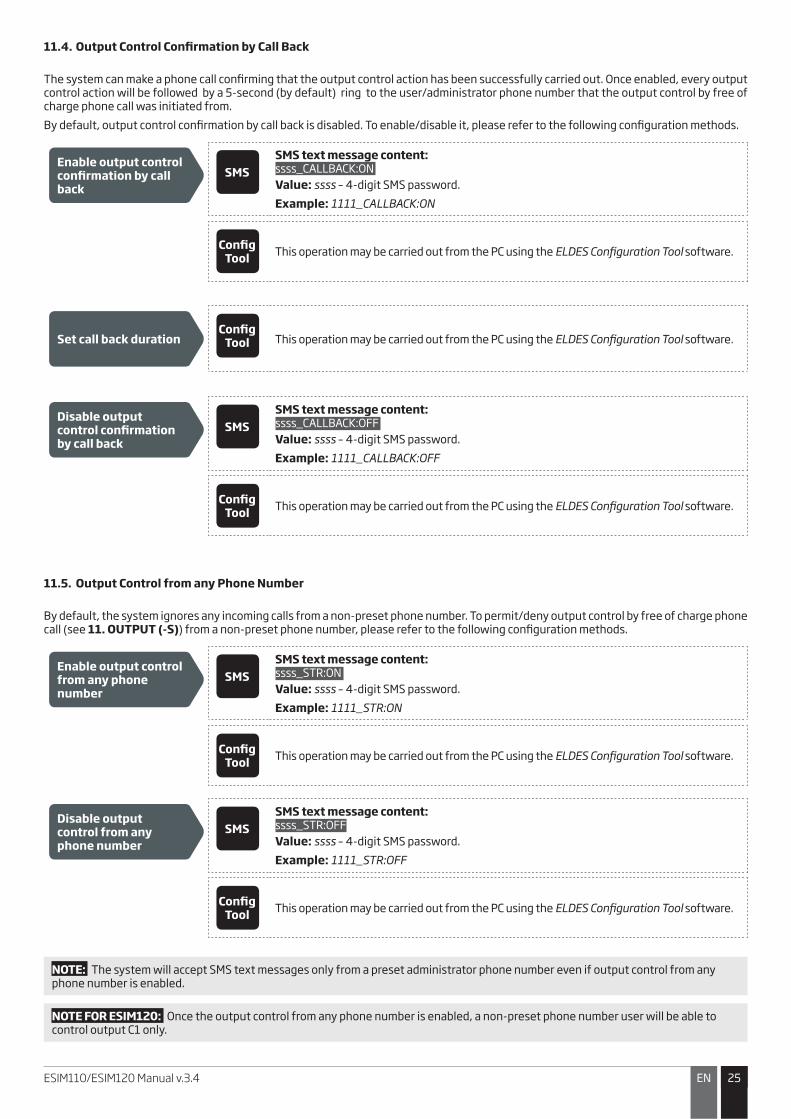
11.4. Output Control Confirmation by Call Back
The system can make a phone call confirming that the output control action has been successfully carried out. Once enabled, every output control action will be followed by a 5-second (by default) ring to the user/administrator phone number that the output control by free of charge phone call was initiated from.
By default, output control confirmation by call back is disabled. To enable/disable it, please refer to the following configuration methods.
Enable output control confirmation by call back
SMSSMS text message content:ssss_CALLBACK:ON
Value: ssss – 4-digit SMS password.
Example: 1111_CALLBACK:ON
Config Tool This operation may be carried out from the PC using the ELDES Configuration Tool software.
Set call back durationConfig
Tool This operation may be carried out from the PC using the ELDES Configuration Tool software.
Disable output control confirmation by call back
SMSSMS text message content:ssss_CALLBACK:OFF
Value: ssss – 4-digit SMS password.
Example: 1111_CALLBACK:OFF
Config Tool This operation may be carried out from the PC using the ELDES Configuration Tool software.
11.5. Output Control from any Phone Number
By default, the system ignores any incoming calls from a non-preset phone number. To permit/deny output control by free of charge phone call (see 11. OUTPUT (-S)) from a non-preset phone number, please refer to the following configuration methods.
Enable output control from any phone number
SMSSMS text message content:ssss_STR:ON
Value: ssss – 4-digit SMS password.
Example: 1111_STR:ON
Config Tool This operation may be carried out from the PC using the ELDES Configuration Tool software.
Disable output control from any phone number
SMSSMS text message content:ssss_STR:OFF
Value: ssss – 4-digit SMS password.
Example: 1111_STR:OFF
Config Tool This operation may be carried out from the PC using the ELDES Configuration Tool software.
NOTE: The system will accept SMS text messages only from a preset administrator phone number even if output control from any phone number is enabled.
NOTE FOR ESIM120: Once the output control from any phone number is enabled, a non-preset phone number user will be able to control output C1 only.

2626 EN ESIM110/ESIM120 Manual v.3.4
11.6. Automatic Output Control
The system comes equipped with automatic output control in accordance with the assigned scheduler (-s). When one or more schedulers are assigned, the output will automatically turn ON/OFF on the specified weekdays and time set up in the scheduler. The system allows to assign up to 8 different schedulers. For more details on how to set up the schedulers, please refer to 12. SCHEDULERS.
Assign scheduler
ONLY FOR ESIM110
SMSSMS text message content:ssss_OSHED1_c:ON
Value: ssss – 4-digit SMS password; c – scheduler number; range – [1... 8].
Example: 1111_OSCHED1_8:ON
Config Tool This operation may be carried out from the PC using the ELDES Configuration Tool software.
Remove scheduler
ONLY FOR ESIM110
SMSSMS text message content:ssss_OSHED1_c:OFF
Value: ssss – 4-digit SMS password; c – scheduler number; range – [1... 8].
Example: 1111_OSCHED1_3:OFF
Config Tool This operation may be carried out from the PC using the ELDES Configuration Tool software.
Assign scheduler
ONLY FOR ESIM120
SMSSMS text message content:ssss_OSHEDo_c:ON
Value: ssss – 4-digit SMS password; o – output number, range [1 – output C1; 2 – output C2]; c – scheduler number; range – [1... 8].
Example: 1111_OSCHED2_1:ON
Config Tool This operation may be carried out from the PC using the ELDES Configuration Tool software.
Remove scheduler
ONLY FOR ESIM120
SMSSMS text message content:ssss_OSHEDo_c:OFF
Value: ssss – 4-digit SMS password; o – output number, range [1 – output C1; 2 – output C2]; c – scheduler number; range – [1... 8].
Example: 1111_OSCHED1_5:OFF
Config Tool This operation may be carried out from the PC using the ELDES Configuration Tool software.
ATTENTION: Once the scheduler, set up for automatic output control, comes into effect, the user/administrator will NOT be able to control the output by phone call and SMS text message.
2727ENESIM110/ESIM120 Manual v.3.4
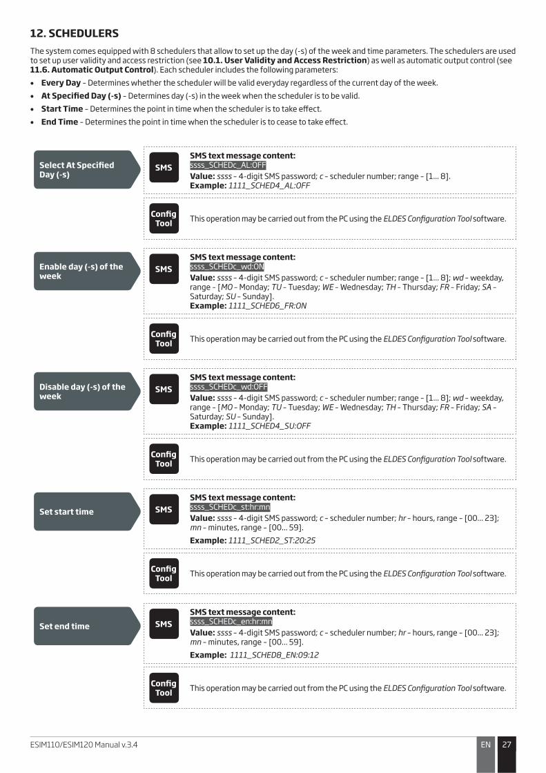
12. SCHEDULERSThe system comes equipped with 8 schedulers that allow to set up the day (-s) of the week and time parameters. The schedulers are used to set up user validity and access restriction (see 10.1. User Validity and Access Restriction) as well as automatic output control (see 11.6. Automatic Output Control). Each scheduler includes the following parameters:
�� Every Day – Determines whether the scheduler will be valid everyday regardless of the current day of the week.
�� At Specified Day (-s) – Determines day (-s) in the week when the scheduler is to be valid.
�� Start Time – Determines the point in time when the scheduler is to take effect.
�� End Time – Determines the point in time when the scheduler is to cease to take effect.
Select At Specified Day (-s)
SMSSMS text message content:ssss_SCHEDc_AL:OFF
Value: ssss – 4-digit SMS password; c – scheduler number; range – [1... 8].Example: 1111_SCHED4_AL:OFF
Config Tool This operation may be carried out from the PC using the ELDES Configuration Tool software.
Enable day (-s) of the week
SMSSMS text message content:ssss_SCHEDc_wd:ON
Value: ssss – 4-digit SMS password; c – scheduler number; range – [1... 8]; wd – weekday, range – [MO – Monday; TU – Tuesday; WE – Wednesday; TH – Thursday; FR – Friday; SA – Saturday; SU – Sunday].Example: 1111_SCHED6_FR:ON
Config Tool This operation may be carried out from the PC using the ELDES Configuration Tool software.
Disable day (-s) of the week
SMSSMS text message content:ssss_SCHEDc_wd:OFF
Value: ssss – 4-digit SMS password; c – scheduler number; range – [1... 8]; wd – weekday, range – [MO – Monday; TU – Tuesday; WE – Wednesday; TH – Thursday; FR – Friday; SA – Saturday; SU – Sunday].Example: 1111_SCHED4_SU:OFF
Config Tool This operation may be carried out from the PC using the ELDES Configuration Tool software.
Set start time SMSSMS text message content:ssss_SCHEDc_st:hr:mn
Value: ssss – 4-digit SMS password; c – scheduler number; hr – hours, range – [00... 23]; mn – minutes, range – [00... 59].
Example: 1111_SCHED2_ST:20:25
Config Tool This operation may be carried out from the PC using the ELDES Configuration Tool software.
Set end time SMSSMS text message content:ssss_SCHEDc_en:hr:mn
Value: ssss – 4-digit SMS password; c – scheduler number; hr – hours, range – [00... 23]; mn – minutes, range – [00... 59].
Example: 1111_SCHED8_EN:09:12
Config Tool This operation may be carried out from the PC using the ELDES Configuration Tool software.
2828 EN ESIM110/ESIM120 Manual v.3.4
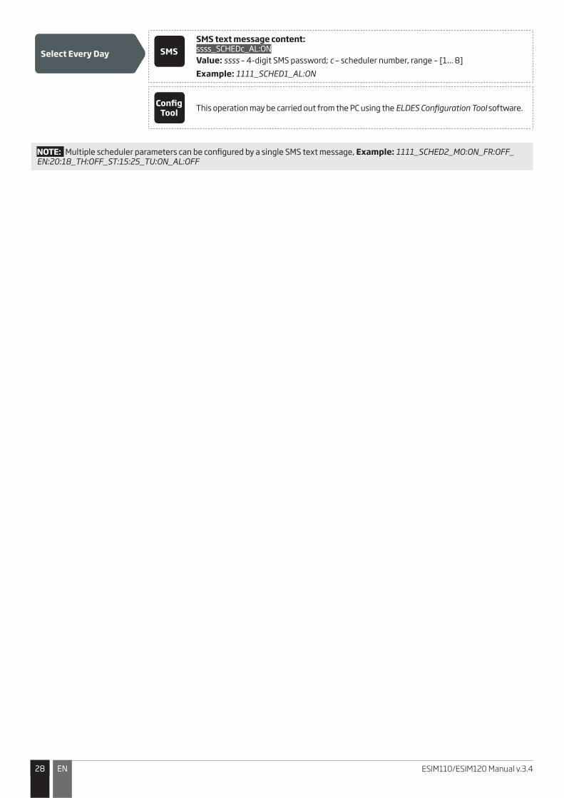
Select Every Day SMSSMS text message content:ssss_SCHEDc_AL:ON
Value: ssss – 4-digit SMS password; c – scheduler number, range – [1... 8]
Example: 1111_SCHED1_AL:ON
Config Tool This operation may be carried out from the PC using the ELDES Configuration Tool software.
NOTE: Multiple scheduler parameters can be configured by a single SMS text message, Example: 1111_SCHED2_MO:ON_FR:OFF_ EN:20:18_TH:OFF_ST:15:25_TU:ON_AL:OFF

2929ENESIM110/ESIM120 Manual v.3.4
13. EVENT LOGThis feature allows to chronologically register up to 1000 timestamped records regarding the following system events:
�� Output control including the user/administrator phone number and user name.
�� User validity expiry by deadline.
�� User validity expiry by ring counter.
�� Automatic output control beginning.
�� Automatic output control ending.
To export the event log to .log file or clear it, please refer to the following configuration methods.
Export event logConfig
Tool This operation may be carried out from the PC using the ELDES Configuration Tool software.
By default, when the event log reaches the 1000 record limit, the system will send the notification by SMS text message to the administrator phone number. To clear the event log and/or disable/enable the notification regarding the full event log, please refer to the following configuration methods.
Clear event log SMSSMS text message content:ssss_DELETELOG
Value: ssss – 4-digit SMS password.
Example: 1111_DELETELOG
Config Tool This operation may be carried out from the PC using the ELDES Configuration Tool software.
Disable Log Full notification
Config Tool This operation may be carried out from the PC using the ELDES Configuration Tool software.
Enable Log Full notification
Config Tool This operation may be carried out from the PC using the ELDES Configuration Tool software.
The event log may be set as of LIFO (last in, first out) type that allows the system to automatically replace the oldest records with the the latest ones. By default, LIFO type event log is disabled. To enable/disable it, please refer to the following configuration methods.
Enable LIFO type logConfig
Tool This operation may be carried out from the PC using the ELDES Configuration Tool software.
Disable LIFO type logConfig
Tool This operation may be carried out from the PC using the ELDES Configuration Tool software.

3030 EN ESIM110/ESIM120 Manual v.3.4
14. INPUTSThe system comes equipped with 3 inputs designed for fault indication output or detection device connection, such as door contacts. Once a fault indication output and/or a detection device is triggered, the system will send a notification to the administrator phone number. Typically, the inputs are used to receive notifications regarding jammed gate or gate state. For more details, please refer to 14.1. Input Names and Alarm Notifications.
Each input’s sensitivity level can be customized by a delay time (by default – 600 milliseconds). If an input is left triggered until the delay time expires, the input is considered violated.
Set input delay SMSSMS text message content:ssss_Tn:in-delay
Value: ssss – 4-digit SMS password; n – input number, range – [1... 3]; in-delay – input delay, range – [100... 42000000] milliseconds.
Example: 1111_T3:10500
Config Tool This operation may be carried out from the PC using the ELDES Configuration Tool software.
The system allows to view the current input state by the following configuration method.
View input state SMSSMS text message content:ssss_INFO
Value: ssss – 4-digit SMS password;
Example: 1111_INFO
14.1. Input Names and Alarm Notifications
Each input has a name that can be customized. Typically, the name specifies a device type connected to a certain input terminal, for example: GateOpen. The input names are used in notifications that are sent by SMS text message to the administrator regarding the input alarm event. By default, the input names are: Z1 – zone1, Z2 – zone2, Z3 – zone3.
Set input name SMSSMS text message content:ssss_Zn:input-name
Value: ssss – 4-digit SMS password; n – input number, range – [1... 3]; input-name – up to 8 characters input name.
Example: 1111_Z2:GateOpen
Config Tool This operation may be carried out from the PC using the ELDES Configuration Tool software.
View input names SMSSMS text message content:ssss_STATUS
Value: ssss – 4-digit SMS password.
Example: 1111_STATUS
Config Tool This operation may be carried out from the PC using the ELDES Configuration Tool software.
By default, the system sends SMS text message to the first available administrator in case of input alarm. If the system did not receive the SMS delivery report during 20 seconds, it will attempt to send the SMS text message to the next preset administrator phone number. To ignore the SMS delivery report and allow/disallow the system to send the SMS text message to every preset administrator phone number, please refer to the following configuration methods.
3131ENESIM110/ESIM120 Manual v.3.4
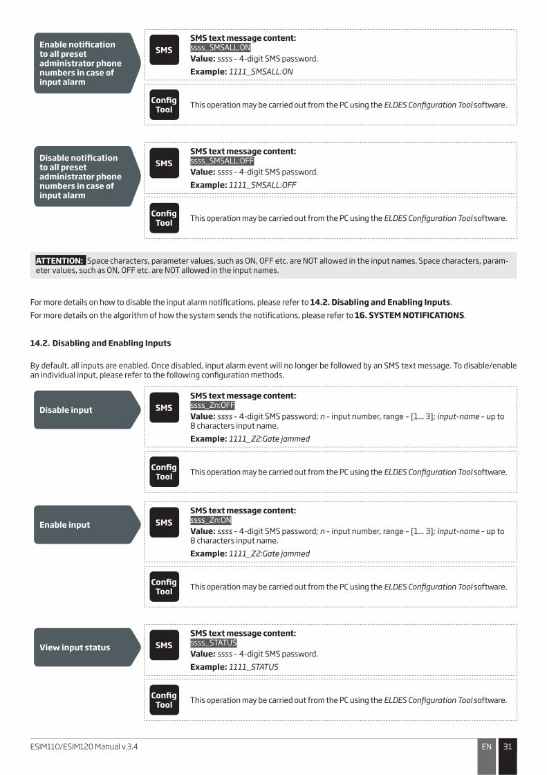
Enable notification to all preset administrator phone numbers in case of input alarm
SMSSMS text message content:ssss_SMSALL:ON
Value: ssss – 4-digit SMS password.
Example: 1111_SMSALL:ON
Config Tool This operation may be carried out from the PC using the ELDES Configuration Tool software.
Disable notification to all preset administrator phone numbers in case of input alarm
SMSSMS text message content:ssss_SMSALL:OFF
Value: ssss – 4-digit SMS password.
Example: 1111_SMSALL:OFF
Config Tool This operation may be carried out from the PC using the ELDES Configuration Tool software.
ATTENTION: Space characters, parameter values, such as ON, OFF etc. are NOT allowed in the input names. Space characters, param-eter values, such as ON, OFF etc. are NOT allowed in the input names.
For more details on how to disable the input alarm notifications, please refer to 14.2. Disabling and Enabling Inputs.
For more details on the algorithm of how the system sends the notifications, please refer to 16. SYSTEM NOTIFICATIONS.
14.2. Disabling and Enabling Inputs
By default, all inputs are enabled. Once disabled, input alarm event will no longer be followed by an SMS text message. To disable/enable an individual input, please refer to the following configuration methods.
Disable input SMSSMS text message content:ssss_Zn:OFF
Value: ssss – 4-digit SMS password; n – input number, range – [1... 3]; input-name – up to 8 characters input name.
Example: 1111_Z2:Gate jammed
Config Tool This operation may be carried out from the PC using the ELDES Configuration Tool software.
Enable input SMSSMS text message content:ssss_Zn:ON
Value: ssss – 4-digit SMS password; n – input number, range – [1... 3]; input-name – up to 8 characters input name.
Example: 1111_Z2:Gate jammed
Config Tool This operation may be carried out from the PC using the ELDES Configuration Tool software.
View input status SMSSMS text message content:ssss_STATUS
Value: ssss – 4-digit SMS password.
Example: 1111_STATUS
Config Tool This operation may be carried out from the PC using the ELDES Configuration Tool software.
3232 EN ESIM110/ESIM120 Manual v.3.4
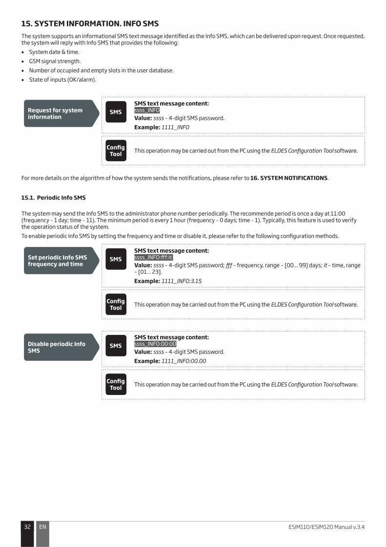
15. SYSTEM INFORMATION. INFO SMSThe system supports an informational SMS text message identified as the Info SMS, which can be delivered upon request. Once requested, the system will reply with Info SMS that provides the following:
�� System date & time.
�� GSM signal strength.
�� Number of occupied and empty slots in the user database.
�� State of inputs (OK/alarm).
Request for system information
SMSSMS text message content:ssss_INFO
Value: ssss – 4-digit SMS password.
Example: 1111_INFO
Config Tool This operation may be carried out from the PC using the ELDES Configuration Tool software.
For more details on the algorithm of how the system sends the notifications, please refer to 16. SYSTEM NOTIFICATIONS.
15.1. Periodic Info SMS
The system may send the Info SMS to the administrator phone number periodically. The recommende period is once a day at 11:00 (frequency – 1 day; time – 11). The minimum period is every 1 hour (frequency – 0 days; time – 1). Typically, this feature is used to verify the operation status of the system.
To enable periodic Info SMS by setting the frequency and time or disable it, please refer to the following configuration methods.
Set periodic Info SMS frequency and time
SMSSMS text message content:ssss_INFO:fff:it
Value: ssss – 4-digit SMS password; fff – frequency, range – [00... 99] days; it – time, range – [01... 23].
Example: 1111_INFO:3.15
Config Tool This operation may be carried out from the PC using the ELDES Configuration Tool software.
Disable periodic Info SMS
SMSSMS text message content:ssss_INFO:00:00
Value: ssss – 4-digit SMS password.
Example: 1111_INFO:00.00
Config Tool This operation may be carried out from the PC using the ELDES Configuration Tool software.
3333ENESIM110/ESIM120 Manual v.3.4
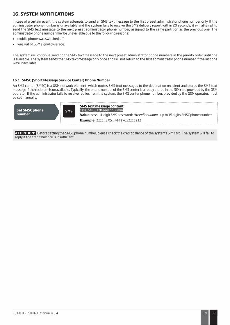
16. SYSTEM NOTIFICATIONSIn case of a certain event, the system attempts to send an SMS text message to the first preset administrator phone number only. If the administrator phone number is unavailable and the system fails to receive the SMS delivery report within 20 seconds, it will attempt to send the SMS text message to the next preset administrator phone number, assigned to the same partition as the previous one. The administrator phone number may be unavailable due to the following reasons:
�� mobile phone was switched off.
�� was out of GSM signal coverage.
The system will continue sending the SMS text message to the next preset administrator phone numbers in the priority order until one is available. The system sends the SMS text message only once and will not return to the first administrator phone number if the last one was unavailable.
16.1. SMSC (Short Message Service Center) Phone NumberAn SMS center (SMSC) is a GSM network element, which routes SMS text messages to the destination recipient and stores the SMS text message if the recipient is unavailable. Typically, the phone number of the SMS center is already stored in the SIM card provided by the GSM operator. If the administrator fails to receive replies from the system, the SMS center phone number, provided by the GSM operator, must be set manually.
Set SMSC phone number
SMSSMS text message content:ssss_SMS_+ttteeellnnuumm
Value: ssss – 4-digit SMS password; ttteeellnnuumm – up to 15 digits SMSC phone number.
Example: 1111_SMS_+4417031111111
ATTENTION: Before setting the SMSC phone number, please check the credit balance of the system’s SIM card. The system will fail to reply if the credit balance is insufficient.

3434 EN ESIM110/ESIM120 Manual v.3.4
17. GPRS NETWORK SETTINGSThe GPRS network settings are used for device communication with the remote configuration server or Smart Gate server via GPRS connection. To set the GPRS network settings, please refer to the following configuration methods.
Set APN SMSSMS text message content:ssss_SETGPRS:APN:acc-point-name
Value: ssss – 4-digit SMS password; acc-point-name – up to 31 character APN (Access Point Name) provided by the GSM operator.
Example: 1111_SETGPRS:APN:internet
Config Tool This operation may be carried out from the PC using the ELDES Configuration Tool software.
Set user name SMSSMS text message content:ssss_SETGPRS:USER:usr-name
Value: ssss – 4-digit SMS password; usr-name – up to 31 character user name provided by the GSM operator. Example: 1111_USER:mobileusr
Config Tool This operation may be carried out from the PC using the ELDES Configuration Tool software.
Set password SMSSMS text message content:ssss_SETGPRS:PSW:password
Value: ssss – 4-digit SMS password; password – up to 31 character password provided by the GSM operator.
Example: 1111_SETGPRS:PSW:mobilepsw
Config Tool This operation may be carried out from the PC using the ELDES Configuration Tool software.
View GPRS network settings
SMSSMS text message content:ssss_SETGPRS?
Value: ssss – 4-digit SMS password.
Example: 1111_SETGPRS?
Config Tool This operation may be carried out from the PC using the ELDES Configuration Tool software.
NOTE: Multiple parameters can be set by single SMS text message, Example: 1111_SETGPRS:APN:internet;USER:mobileusr;PSW:mobilepsw
3535ENESIM110/ESIM120 Manual v.3.4
18. INCOMING PHONE NUMBER VERIFICATION SETTINGS
ATTENTION: Due to security reasons it is NOT recommended to configure the parameters described below.
The system comes equipped with a phone number length verification feature allowing to restrict access for the phone numbers of a certain length. By default, the system supports the administrator and user phone numbers consisting of at least 4 digits (minimum phone number length), while the last 7 digits of the incoming call’s phone number are used for comparison with the preset phone number in order to identify whether the phone number is preset in the system. By default, the system will ignore all phone numbers that consist of less than 4 digits even if the phone number is preset as the administrator phone number or the user phone number as well as it will accept all incoming calls containing a phone number matching the last 7 digits of the preset phone number.
Manage incoming phone number verification settings
Config Tool This operation may be carried out from the PC using the ELDES Configuration Tool software.
19. REMOTE SYSTEM RESTARTIn some critical situations, a system restart may be required. To remotely carry out system restart, please refer to the following configuration method.
Restart the system SMSSMS text message content:ssss_RESTART
Value: ssss – 4-digit SMS password.
Example: 1111_RESTART

3636 EN ESIM110/ESIM120 Manual v.3.4
20. TECHNICAL SUPPORT
20.1. Troubleshooting
Indication Possible reason
Indicators SIM STAT and NETW are OFF · No mains power
· Wrong wiring
· Blown fuse
· Disconnected antenna
· Micro-controller could not start due to electrical mains noise or static discharge
Indicator SIM STAT is ON · Missing SIM card
· PIN code is enabled
· SIM card is inactive
Indicator SIM STAT is flashing · GSM connection fault
Unable to receive any SMS text messages to
the administrator phone number or control the
output
· Insufficient SIM card credit balance
· Caller's phone number is set up as withheld (hidden)
· No GSM network signal
· Wrong administrator/user phone number
· Administrator/user phone number is not set
· SIM card was replaced before disconnecting mains power
· Incorrect SMS center phone number
Unable to connect to the device remotely via
GPRS connection
· GPRS settings (APN, user name, password) not set.
· Insufficient SIM card credit balance
· Mobile internet service (GPRS) not activated on the SIM card.
Received SMS text message “Wrong syntax” · Incorrect SMS text message structure
· Unnecessary space character might have been typed in SMS text message
20.2. Restoring Default Parameters1. Power down the device.
2. Short-circuit (connect) the DEF pins.
3. Power up the device for 7 seconds.
4. Power down the device.
5. Remove the short-circuit from DEF pins.
6. Parameters restored to default.
20.3. Updating the Firmware via USB Cable1. Power down the device.
2. Short-circuit (connect) the DEF pins.
3. Connect the device via USB cable to the PC.
4. Power up the device.
5. The new window must pop-up where you will find the .bin file. Otherwise open My Computer and look for Boot Disk drive.
6. Delete the .bin file found in the drive.
7. Copy the new firmware .bin file to the very same window.
8. Power down the device.
9. Unplug the USB cable.
10. Remove the short-circuit from DEF pins.
11. Power up the device.
12. Firmware updated.
NOTE: It is strongly recommended to restore default parameters after the firmware update.

3737ENESIM110/ESIM120 Manual v.3.4
21. SMART GATE
ELDES Smart Gate is a sub-platform of ELDES Smart Security. It has been designed exclusively for ESIM120 GSM switch-gate controller monitoring, control and remote configuration. The solution consists of:• ESIM120 • Gate automation device • Android widget/iOS application • Administration interface via web • ELDES Smart Security server
ESIM120
Android aplication/widget or iOS application Android widget/iOS
application
Web interface
Database UserAdministration interface
Administrator/Power-admin
Coming
up in the
future
User hierarchy
Distributor
Power-Admin
Administrator
Database userFor more details on Smart Gate solution, please refer Smart Security and Smart Gate user manuals located at www.eldes.lt/download

3838 EN ESIM110/ESIM120 Manual v.3.4
Copyright © “ELDES UAB”, 2014. All rights reserved
It is not allowed to copy and distribute information in this document or pass to a third party without advanced written authorization by “ELDES UAB”. “ELDES UAB” reserves the right to update or modify this document and/or related prod-ucts without a warning. Hereby, “ELDES UAB” declares that the GSM swtich-gate controller ESIM110/ESIM120 is in compliance with the essential requirements and other relevant provisions of Directive 1999/5/EC. The declaration of conformity may be consulted at www.eldes.lt
22. RELATED PRODUCTS
ME1 – metal cabinet
EBU1 – power backup unit
Power supply
IP66 - plastic enclosure

GPRS USER MANUAL
GSM GATE CONTROLLER ESIM120
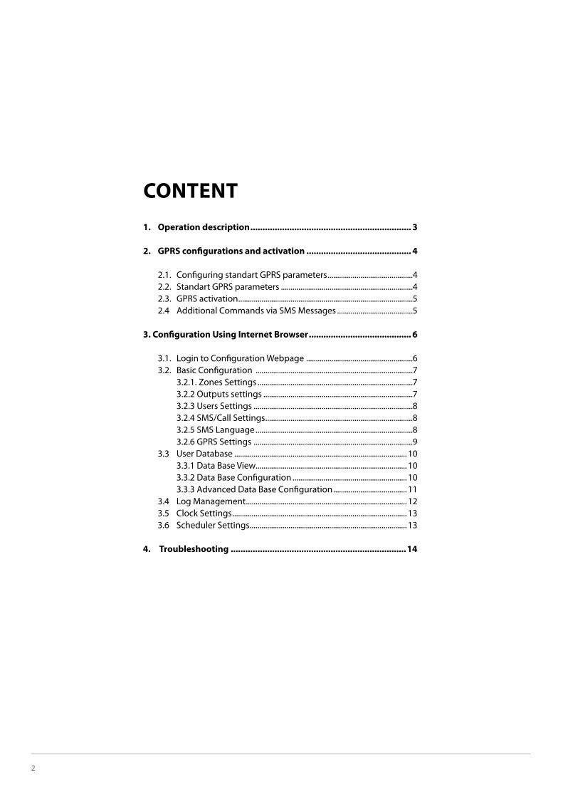
2
CONTENT1. Operation description .................................................................. 3
2. GPRS configurations and activation ........................................... 4
2.1. Configuring standart GPRS parameters ............................................4 2.2. Standart GPRS parameters ....................................................................4 2.3. GPRS activation ..........................................................................................5 2.4 Additional Commands via SMS Messages .......................................5
3. Configuration Using Internet Browser .......................................... 6
3.1. Login to Configuration Webpage .......................................................6 3.2. Basic Configuration .................................................................................7 3.2.1. Zones Settings ................................................................................7 3.2.2 Outputs settings .............................................................................7 3.2.3 Users Settings ..................................................................................8 3.2.4 SMS/Call Settings ............................................................................8 3.2.5 SMS Language .................................................................................8 3.2.6 GPRS Settings ..................................................................................9 3.3 User Database ......................................................................................... 10 3.3.1 Data Base View.............................................................................. 10 3.3.2 Data Base Configuration ........................................................... 10 3.3.3 Advanced Data Base Configuration ...................................... 11 3.4 Log Management ................................................................................... 12 3.5 Clock Settings .......................................................................................... 13 3.6 Scheduler Settings ................................................................................. 13
4. Troubleshooting ........................................................................14
ESIM120 GPRS USER MANUAL 3
1. Operation descriptionSince July 2010 software supporting GRPS connection is installed in automatic gate controller ESIM120. The users will be able to quickly perform configurations not only connecting the device to their computer but also remotely – using web browser.
GPRS connection is activated according to the standard GPRS parameters which are stored in device memory or according to one-time GPRS parameters. These parameters are activated by sending the corresponding command via SMS message. One-time GPRS parameters are valid only for one connection session (the system uses standard GPRS parameters with one or several indicated changes). Standard GPRS parameters (Table 1) are changed by SMS messages, using special software or by connecting via web browser.
One of the main GPRS parameters is the mode, i. e. Server or Client, which describes the way ESIM120 configuration web environment is reached i. e. connecting directly to the device or through transitional server. In this case after activating Client mode the administrator will be able to connect to the device through the internet website defined by the provider and the connection will be maintained through the transitional server. After activating Server mode the administrator connects directly to ESIM120 using web browser. However, this mode will operate only in the case GSM operator of the SIM card used in the device provides a static IP address. It is also necessary to mention that GPRS connection is activated only for a particular period (session time) and after this period is over it is ended automatically. In such a case, if the administrator wants to continue configuring ESIM120 it is necessary to reactivate GPRS connection and to connect using the new login data.
Before activating GPRS connection, administrator must ensure the following conditions:
number.
A short description of actions that should be taken in order to successfully use ESIM120 configuration web environment:
1. If requested, corrections are made in the standard GPRS parameters (refer to chapter 2.1 Configuring standard GPRS Parameters);
2. The administrator sends SMS message with GPRS activation command from the mobile phone number registered in the system (refer to chapter 2.3 GPRS Activation);
3. The system sends SMS message with login data (username and password) necessary for connecting to ESIM120 configuration web environment;
4. The administrator opens a corresponding web page (the address is formed depending on the running mode (refer to chapter 3.1 Login to configuration webpge);
5. Configurations or other actions are made in ESIM120 configuration web environment (refer to chapter 3);
6. If session time is not ended after all the tasks are performed, end the connection by sending a corresponding SMS message (refer to chapter 2.4 Additional Commands via SMS messages -> Ending the Session).
ATTENTION: by factory default settings the administrator can connect to ESIM120 device using a connection form provided in www.eldes.lt/login, and the connection is maintained through ELDES server (ESIM120 works in Client mode with defined ELDES server parameters).
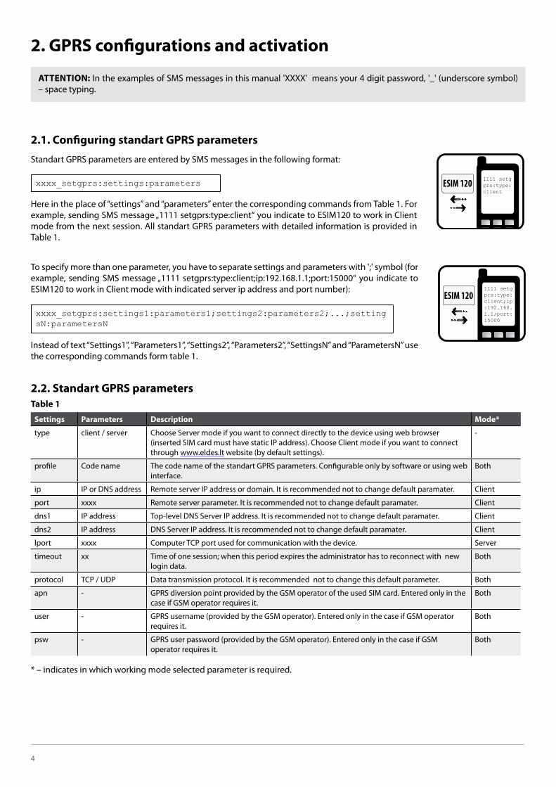
4
2. GPRS configurations and activation
ATTENTION:– space typing.
2.1. Configuring standart GPRS parameters
Standart GPRS parameters are entered by SMS messages in the following format:
Here in the place of “settings” and “parameters” enter the corresponding commands from Table 1. For example, sending SMS message „1111 setgprs:type:client“ you indicate to ESIM120 to work in Client mode from the next session. All standart GPRS parameters with detailed information is provided in Table 1.
example, sending SMS message „1111 setgprs:type:client;ip:192.168.1.1;port:15000“ you indicate to ESIM120 to work in Client mode with indicated server ip address and port number):
Instead of text “Settings1”, “Parameters1”, “Settings2”, “Parameters2”, “SettingsN” and “ParametersN” use the corresponding commands form table 1.
2.2. Standart GPRS parametersTable 1
Settings Parameters Description Mode*
type client / server Choose Server mode if you want to connect directly to the device using web browser (inserted SIM card must have static IP address). Choose Client mode if you want to connect through www.eldes.lt website (by default settings).
-
profile Code name The code name of the standart GPRS parameters. Configurable only by software or using web interface.
Both
ip IP or DNS address Remote server IP address or domain. It is recommended not to change default paramater. Client
port xxxx Remote server parameter. It is recommended not to change default paramater. Client
dns1 IP address Top-level DNS Server IP address. It is recommended not to change default paramater. Client
dns2 IP address DNS Server IP address. It is recommended not to change default paramater. Client
lport xxxx Computer TCP port used for communication with the device. Server
timeout xx Time of one session; when this period expires the administrator has to reconnect with new login data.
Both
protocol TCP / UDP Data transmission protocol. It is recommended not to change this default parameter. Both
apn - GPRS diversion point provided by the GSM operator of the used SIM card. Entered only in the case if GSM operator requires it.
Both
user - GPRS username (provided by the GSM operator). Entered only in the case if GSM operator requires it.
Both
psw - GPRS user password (provided by the GSM operator). Entered only in the case if GSM operator requires it.
Both
* – indicates in which working mode selected parameter is required.
xxxx_setgprs:settings:parameters
xxxx_setgprs:settings1:parameters1;settings2:parameters2;...;settingsN:parametersN
ESIM 120 1111 setg prs:type: client
ESIM 1201111 setg prs:type: client;ip :192.168. 1.1;port: 15000
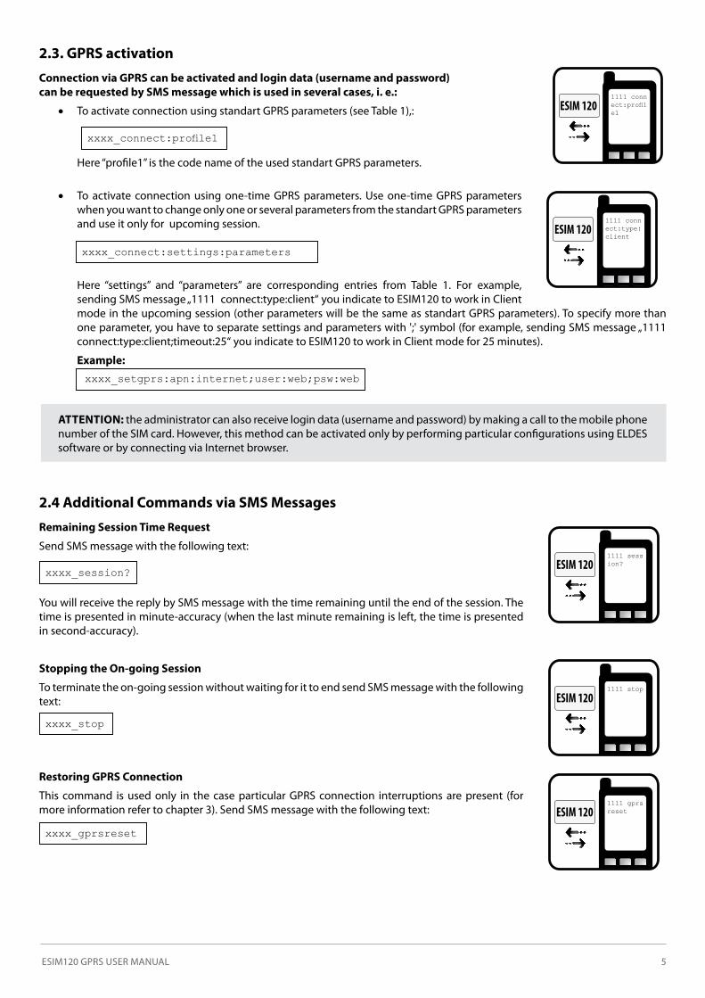
ESIM120 GPRS USER MANUAL 5
2.3. GPRS activation
Connection via GPRS can be activated and login data (username and password) can be requested by SMS message which is used in several cases, i. e.:
�� To activate connection using standart GPRS parameters (see Table 1),:
Here “profile1” is the code name of the used standart GPRS parameters.
�� To activate connection using one-time GPRS parameters. Use one-time GPRS parameters when you want to change only one or several parameters from the standart GPRS parameters and use it only for upcoming session.
Here “settings” and “parameters” are corresponding entries from Table 1. For example, sending SMS message „1111 connect:type:client“ you indicate to ESIM120 to work in Client mode in the upcoming session (other parameters will be the same as standart GPRS parameters). To specify more than
connect:type:client;timeout:25“ you indicate to ESIM120 to work in Client mode for 25 minutes).
Example: xxxx_setgprs:apn:internet;user:web;psw:web
ATTENTION: the administrator can also receive login data (username and password) by making a call to the mobile phone number of the SIM card. However, this method can be activated only by performing particular configurations using ELDES software or by connecting via Internet browser.
2.4 Additional Commands via SMS Messages
Remaining Session Time Request
Send SMS message with the following text:
You will receive the reply by SMS message with the time remaining until the end of the session. The time is presented in minute-accuracy (when the last minute remaining is left, the time is presented in second-accuracy).
Stopping the On-going Session
To terminate the on-going session without waiting for it to end send SMS message with the following text:
Restoring GPRS Connection
This command is used only in the case particular GPRS connection interruptions are present (for more information refer to chapter 3). Send SMS message with the following text:
��������������� ��
xxxx_connect:settings:parameters
ESIM 1201111 conn ������ e1
ESIM 1201111 conn ect:type: client
xxxx_session?
xxxx_stop
xxxx_gprsreset
ESIM 1201111 sess ion?
ESIM 1201111 stop
ESIM 1201111 gprs reset
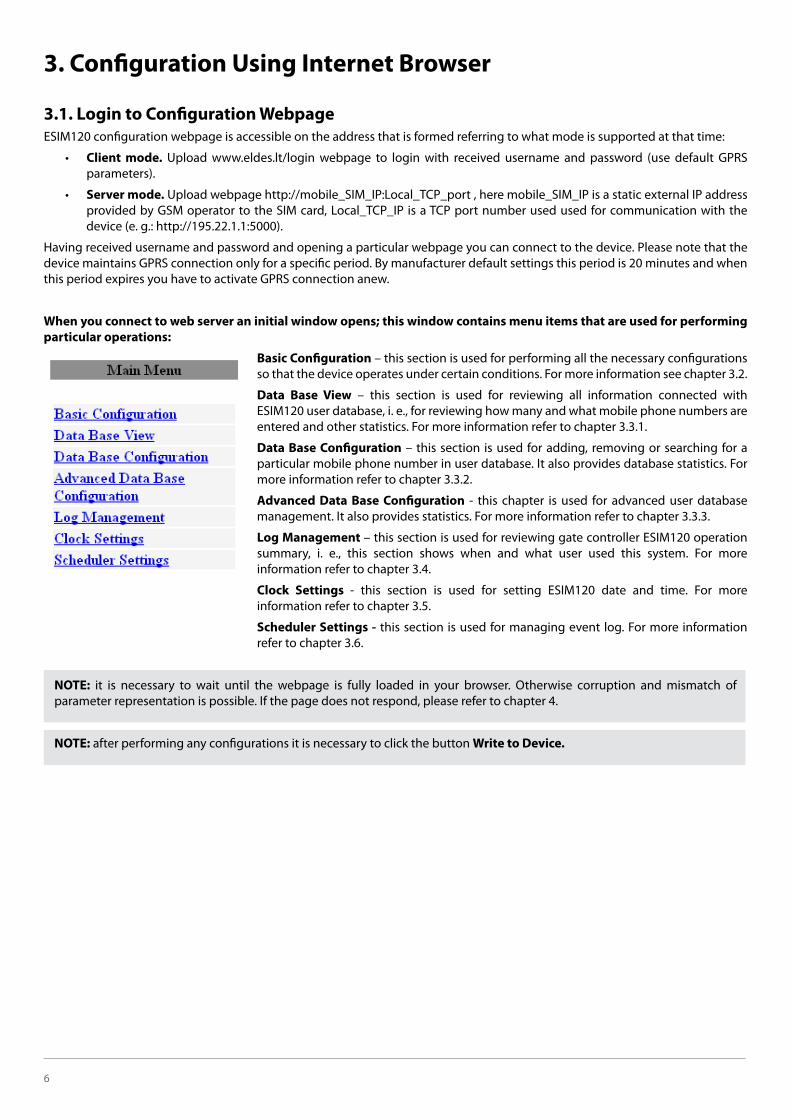
6
3. Configuration Using Internet Browser
3.1. Login to Configuration Webpage ESIM120 configuration webpage is accessible on the address that is formed referring to what mode is supported at that time:
Client mode. Upload www.eldes.lt/login webpage to login with received username and password (use default GPRS parameters).
Server mode.
device (e. g.: http://195.22.1.1:5000).
Having received username and password and opening a particular webpage you can connect to the device. Please note that the device maintains GPRS connection only for a specific period. By manufacturer default settings this period is 20 minutes and when this period expires you have to activate GPRS connection anew.
When you connect to web server an initial window opens; this window contains menu items that are used for performing particular operations:
Basic Configuration – this section is used for performing all the necessary configurations so that the device operates under certain conditions. For more information see chapter 3.2.
Data Base View – this section is used for reviewing all information connected with ESIM120 user database, i. e., for reviewing how many and what mobile phone numbers are entered and other statistics. For more information refer to chapter 3.3.1.
Data Base Configuration – this section is used for adding, removing or searching for a particular mobile phone number in user database. It also provides database statistics. For more information refer to chapter 3.3.2.
Advanced Data Base Configuration - this chapter is used for advanced user database management. It also provides statistics. For more information refer to chapter 3.3.3.
Log Management – this section is used for reviewing gate controller ESIM120 operation summary, i. e., this section shows when and what user used this system. For more information refer to chapter 3.4.
Clock Settings - this section is used for setting ESIM120 date and time. For more information refer to chapter 3.5.
Scheduler Settings - this section is used for managing event log. For more information refer to chapter 3.6.
NOTE: it is necessary to wait until the webpage is fully loaded in your browser. Otherwise corruption and mismatch of parameter representation is possible. If the page does not respond, please refer to chapter 4.
NOTE: after performing any configurations it is necessary to click the button Write to Device.

ESIM120 GPRS USER MANUAL 7
3.2. Basic Configuration The section Basic Configuration can be used for performing all the necessary device configurations, i. e., for changing administrator data, their informational settings, for changing the main password or device system parameters etc. These configurations can be performed by selecting a respective menu item:
Zone Settings – Menu section where you can select settings related with device input control. For more information please refer to chapter 3.2.1.
Outputs Settings – Menu section where you can select settings related with device output control. For more information please refer to chapter 3.2.2.
User Settings – Menu section used for entering administrator data, update the main password and change particular control settings. For more information please refer to chapter 3.2.3 and 3.2.4.
SMS/Call Settings – Menu section where you can configure control and informing settings. For more information please refer to chapter 3.2.4.
GPRS Settings – This section is used for adjusting GPRS connection settings. For more information please refer to chapter 3.2.6.
3.2.1. Zones Settings
Zone Enable – Enables/disables status checking of specific inputs.
Zone1 Delay – Indicates that the system will sense the impulse, transmitted to a particular input, duration if it is longer than the preset value. The specified parameter must be in the range of 100 – 42000000, counted in milliseconds (1 second – 1000 milliseconds).
Text Z1... Z3 – Code name of a particular input. It is recommended to create the name that would most accurately describe the connected device. The name cannot be longer than 8 characters (you cannot use commas, full stops, semicolons or spaces).
3.2.2 Outputs settings
Output1... 2 Delay - Output impulse duration. The default parameter set by the manufacturer is 2 seconds.
Sh1... 8 - The number of scheduler according to which the specified output operates. For more information please refer to chapter 3.6.
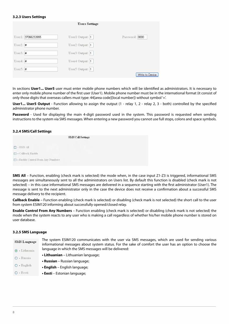
8
3.2.3 Users Settings
In sections User1... User5 user must enter mobile phone numbers which will be identified as administrators. It is necessary to enter only mobile phone number of the first user (User1). Mobile phone number must be in the international format (it consist of only those digits that overseas callers must type: 44[area code][local number]) without symbol ‘+’.
User1... User5 Output - Function allowing to assign the output (1 - relay 1, 2 - relay 2, 3 - both) controlled by the specified administrator phone number.
Password - Used for displaying the main 4-digit password used in the system. This password is requested when sending instructions to the system via SMS messages. When entering a new password you cannot use full stops, colons and space symbols.
3.2.4 SMS/Call Settings
SMS All – Function, enabling (check mark is selected) the mode when, in the case input Z1-Z3 is triggered, informational SMS messages are simultaneously sent to all the administrators on Users list. By default this function is disabled (check mark is not selected) – in this case informational SMS messages are delivered in a sequence starting with the first administrator (User1). The message is sent to the next administrator only in the case the device does not receive a confirmation about a successful SMS message delivery to the recipient.
Callback Enable – Function enabling (check mark is selected) or disabling (check mark is not selected) the short call to the user from system ESIM120 informing about successfully opened/closed relay.
Enable Control From Any Numbers – Function enabling (check mark is selected) or disabling (check mark is not selected) the mode when the system reacts to any user who is making a call regardless of whether his/her mobile phone number is stored on user database.
3.2.5 SMS Language
The system ESIM120 communicates with the user via SMS messages, which are used for sending various informational messages about system status. For the sake of comfort the user has an option to choose the language in which the SMS messages will be delivered:
– Lithuanian language;
– Russian language;
– English language;
– Estonian language;

ESIM120 GPRS USER MANUAL 9
3.2.6 GPRS Settings
ATTENTION: this is configuration web interface for the GPRS parameters Changes performed in this section will become effective only after the end of the current session.
Profile – Code name of the current GPRS parameters. The initial name provided by the manufacturer is profile1.
Client – Gate controller ESIM120 is accessible via Internet browser through the intermediate server.
Server – The device will operate in Server mode, i. e. it will be accessible directly via Internet browser without the use of any other additional programs. GSM operator has to provide a static external IP address to the SIM card used on the device.
Server IP – Remote server IP address or domain. It is recommended not to change default paramater.
Server TCP Port – Remote server parameter. It is recommended not to change default paramater.
Session Time – Time of one session; when this period expires the administrator has to connect anew using new login data. By factory default settings this period is 20 minutes.
ATTENTION: when the indicated session time is “0“, connection session will continue until the administrator terminates it by sending a particular SMS message (please refer to chapter 2.3, “Stopping the On-going Session”).
Local TCP Port – Computer TCP port number used for communication with the device. By default settings – 5000 port is activated.
TCP / UDP – Data transmission protocol. Currently only TCP protocol is activated.
DNS1 – Primary DNS server IP address.
DNS2 – Secondary DNS server IP address.
APN – GPRS diversion point provided by GSM operator of the SIM card used in the device. Entered only in the case if GSM operator requires it.
User Name – GPRS username (provided by GSM operator). Entered only in the case if GSM operator requires it.
Password – GPRS password (provided by GSM operator). Entered only in the case if GSM operator requires it.
Start GPRS User1...User5 settings group is used for selecting the administrators that will receive connection data calling on the mobile phone number of the SIM card (otherwise it is necessary to send SMS message with the connection command).
ATTENTION: when Start GPRS User1... User5 settings are activated the selected administrators will not be able to control output (relay) contacts via call. Besides, a repeated call during the session works the same way as sending SMS message for restoring GPRS connection (when the connection is interrupted).
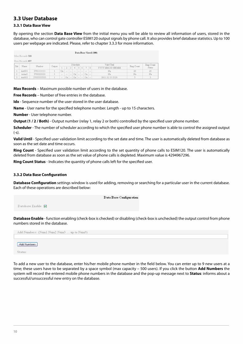
10
3.3 User Database3.3.1 Data Base View
By opening the section Data Base View from the initial menu you will be able to review all information of users, stored in the database, who can control gate controller ESIM120 output signals by phone call. It also provides brief database statistics. Up to 100 users per webpage are indicated. Please, refer to chapter 3.3.3 for more information.
Max Records – Maximum possible number of users in the database.
Free Records – Number of free entries in the database.
Idx - Sequence number of the user stored in the user database.
Name - User name for the specified telephone number. Length - up to 15 characters.
Number - User telephone number.
Output (1 / 2 / Both) - Output number (relay 1, relay 2 or both) controlled by the specified user phone number.
Scheduler - The number of scheduler according to which the specified user phone number is able to control the assigned output (-s).
Valid Until - Specified user validation limit according to the set date and time. The user is automatically deleted from database as soon as the set date and time occurs.
Ring Count - Specified user validation limit according to the set quantity of phone calls to ESIM120. The user is automatically deleted from database as soon as the set value of phone calls is depleted. Maximum value is 4294967296.
Ring Count Status - Indicates the quantity of phone calls left for the specified user.
3.3.2 Data Base Configuration
Database Configuration settings window is used for adding, removing or searching for a particular user in the current database. Each of these operations are described below:
Database Enable - function enabling (check-box is checked) or disabling (check-box is unchecked) the output control from phone numbers stored in the database.
To add a new user to the database, enter his/her mobile phone number in the field below. You can enter up to 9 new users at a time; these users have to be separated by a space symbol (max capacity – 500 users). If you click the button Add Numbers the system will record the entered mobile phone numbers in the database and the pop-up message next to Status: informs about a successful/unsuccessful new entry on the database.
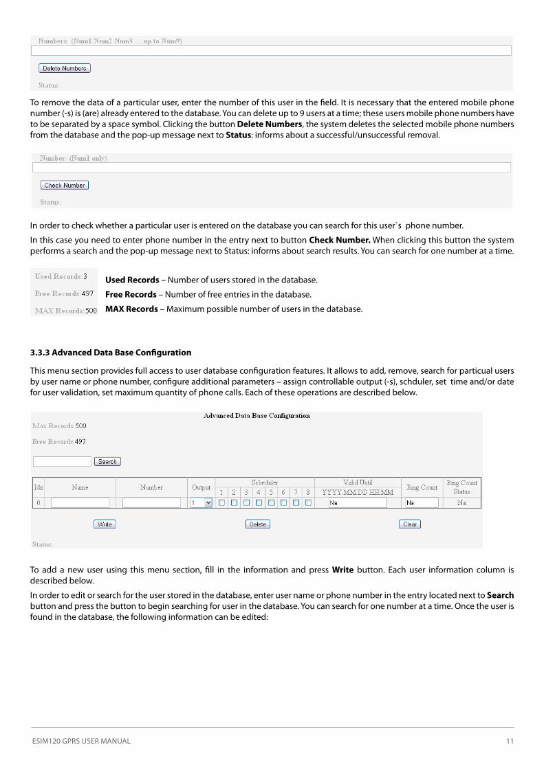
ESIM120 GPRS USER MANUAL 11
To remove the data of a particular user, enter the number of this user in the field. It is necessary that the entered mobile phone number (-s) is (are) already entered to the database. You can delete up to 9 users at a time; these users mobile phone numbers have to be separated by a space symbol. Clicking the button Delete Numbers, the system deletes the selected mobile phone numbers from the database and the pop-up message next to Status: informs about a successful/unsuccessful removal.
In order to check whether a particular user is entered on the database you can search for this user`s phone number.
In this case you need to enter phone number in the entry next to button Check Number. When clicking this button the system performs a search and the pop-up message next to Status: informs about search results. You can search for one number at a time.
Used Records – Number of users stored in the database.
Free Records – Number of free entries in the database.
MAX Records – Maximum possible number of users in the database.
3.3.3 Advanced Data Base Configuration
This menu section provides full access to user database configuration features. It allows to add, remove, search for particual users by user name or phone number, configure additional parameters – assign controllable output (-s), schduler, set time and/or date for user validation, set maximum quantity of phone calls. Each of these operations are described below.
To add a new user using this menu section, fill in the information and press Write button. Each user information column is described below.
In order to edit or search for the user stored in the database, enter user name or phone number in the entry located next to Search button and press the button to begin searching for user in the database. You can search for one number at a time. Once the user is found in the database, the following information can be edited:

12
Idx - Sequence number of the user stored in the user database.
Name - User name for the specified telephone number. Length - up to 15 characters.
Number - User telephone number.
Output (1 / 2 / Both) - Output number (relay 1, relay 2 or both) controlled by the specified user phone number.
Scheduler - The number of scheduler according to which the specified user phone number is able to control the assigned output (-s).
Valid Until - Specified user validation limit according to the set date and time. The user is automatically deleted from database as soon as the set date and time occurs.
Ring Count - Specified user validation limit according to the set quantity of phone calls to ESIM120. The user is automatically deleted from database as soon as the set value of phone calls is depleted. Maximum value is 4294967296.
Ring Count Status - Indicates the quantity of phone calls left for the specified user.
Write button – Saves the changes made to the current user / adds the new user to the database with the parameters set.
Delete button – Deletes the selected user from the database.
Clear button – Clears the user information in the Name, Number, Scheduler, Valid Until, Ring Count columns.
Status - Informs about search results. You can search for one user name/number at a time.
MAX Records – Maximum possible number of users in the database..
Free Records – Number of free entries in the database.
3.4 Log Management
This section is intended for gate controller ESIM120 operation summary file (log file) configuration and downloading.
The system stores a record of every operation performed, such as when and what user opened/closed the gate.
Log Full SMS Enable – By activating this feature (check-box checked) the administrator number receives SMS message about a full ESIM120 operation summary file (SMS messages will be delivered starting with administrator User1 and ending with User5, until the first successful message delivery). In this case it is necessary to empty this file. This parameter does not have any affect in Ring buffer mode enabled.
Log Enable - Function enabling (check-box checked) or disabling (check-box unchecked) the output control from phone numbers stored in the database.
Log Size - Indicates the amount of space the log file occupies in bytes. Maximum size of this file is ~44 KB, i. e., 1000 entries about the usage of gate controller. When this limit is reached no more records are entered in the summary therefore it is necessary to clear this file before further entries can be recorded. Besides, you can receive reminders by SMS message every time the summary file is full and there is no more space left .
To delete all data from summary file check Clear Log check-box and click the button Write to Device
Disable Ring Buffer - Function enabling (check-box unchecked) or disabling (check-box checked) the log ring buffer mode. In this mode the event log never becomes full, since the oldest event records are overwritten with the newest records. The recorded events are always sorted chronologically.
Download Log – Initiates the log file downloading process to the hard drive.
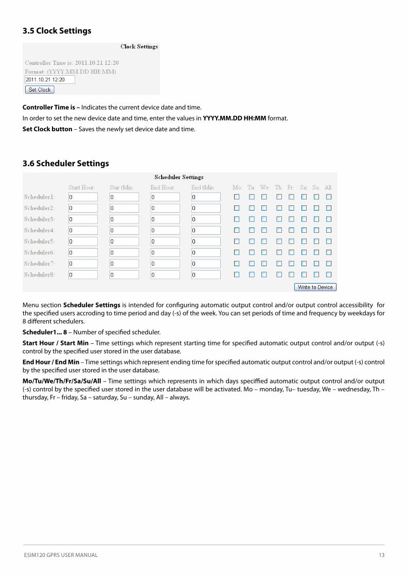
ESIM120 GPRS USER MANUAL 13
3.5 Clock Settings
Controller Time is – Indicates the current device date and time.
In order to set the new device date and time, enter the values in YYYY.MM.DD HH:MM format.
Set Clock button – Saves the newly set device date and time.
3.6 Scheduler Settings
Menu section Scheduler Settings is intended for configuring automatic output control and/or output control accessibility for the specified users accroding to time period and day (-s) of the week. You can set periods of time and frequency by weekdays for 8 different schedulers.
Scheduler1... 8 – Number of specified scheduler.
Start Hour / Start Min – Time settings which represent starting time for specified automatic output control and/or output (-s) control by the specified user stored in the user database.
End Hour / End Min – Time settings which represent ending time for specified automatic output control and/or output (-s) control by the specified user stored in the user database.
Mo/Tu/We/Th/Fr/Sa/Su/All – Time settings which represents in which days speciffied automatic output control and/or output (-s) control by the specified user stored in the user database will be activated. Mo – monday, Tu– tuesday, We – wednesday, Th – thursday, Fr – friday, Sa – saturday, Su – sunday, All – always.
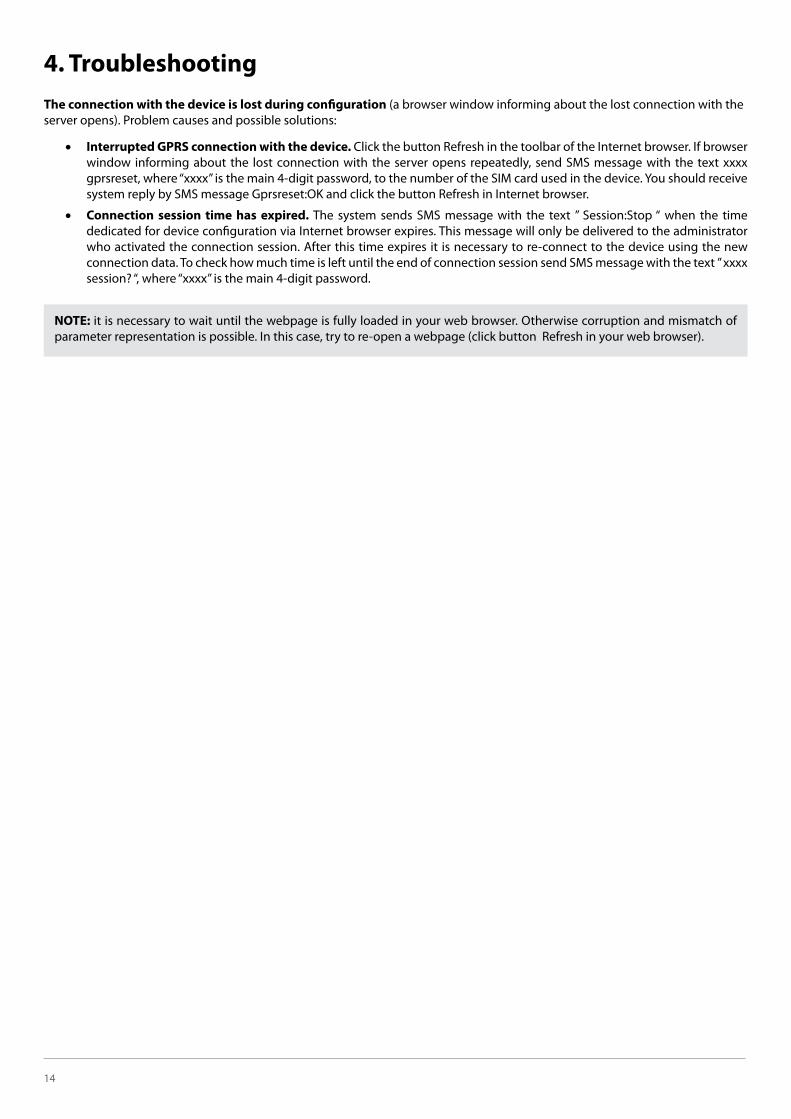
14
4. TroubleshootingThe connection with the device is lost during configuration (a browser window informing about the lost connection with the server opens). Problem causes and possible solutions:
�� Interrupted GPRS connection with the device. Click the button Refresh in the toolbar of the Internet browser. If browser window informing about the lost connection with the server opens repeatedly, send SMS message with the text xxxx gprsreset, where “xxxx” is the main 4-digit password, to the number of the SIM card used in the device. You should receive system reply by SMS message Gprsreset:OK and click the button Refresh in Internet browser.
�� Connection session time has expired. The system sends SMS message with the text ” Session:Stop “ when the time dedicated for device configuration via Internet browser expires. This message will only be delivered to the administrator who activated the connection session. After this time expires it is necessary to re-connect to the device using the new connection data. To check how much time is left until the end of connection session send SMS message with the text ” xxxx session? “, where “xxxx” is the main 4-digit password.
NOTE: it is necessary to wait until the webpage is fully loaded in your web browser. Otherwise corruption and mismatch of parameter representation is possible. In this case, try to re-open a webpage (click button Refresh in your web browser).