escs - esi series
TRANSCRIPT
ESCS - ESI SERIESCATALOGUE
www.enertechmotors.com.au
2 www.enertechmotors.com.au
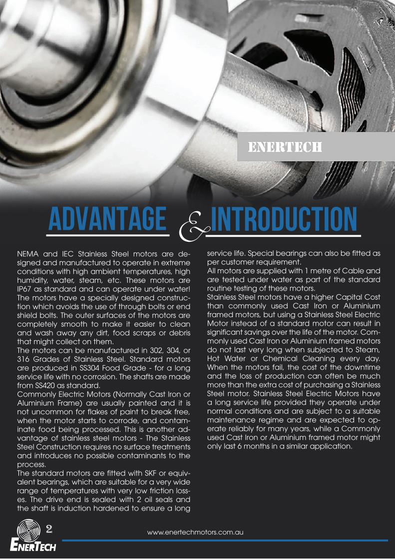
ADVANTAGE INTRODUCTION&NEMA and IEC Stainless Steel motors are de-signed and manufactured to operate in extreme conditions with high ambient temperatures, high humidity, water, steam, etc. These motors are IP67 as standard and can operate under water! The motors have a specially designed construc-tion which avoids the use of through bolts or end shield bolts. The outer surfaces of the motors are completely smooth to make it easier to clean and wash away any dirt, food scraps or debris that might collect on them. The motors can be manufactured in 302, 304, or 316 Grades of Stainless Steel. Standard motors are produced in SS304 Food Grade - for a long service life with no corrosion. The shafts are made from SS420 as standard.Commonly Electric Motors (Normally Cast Iron or Aluminium Frame) are usually painted and it is not uncommon for flakes of paint to break free, when the motor starts to corrode, and contam-inate food being processed. This is another ad-vantage of stainless steel motors - The Stainless Steel Construction requires no surface treatments and introduces no possible contaminants to the process.The standard motors are fitted with SKF or equiv-alent bearings, which are suitable for a very wide range of temperatures with very low friction loss-es. The drive end is sealed with 2 oil seals and the shaft is induction hardened to ensure a long
service life. Special bearings can also be fitted as per customer requirement.All motors are supplied with 1 metre of Cable and are tested under water as part of the standard routine testing of these motors.Stainless Steel motors have a higher Capital Cost than commonly used Cast Iron or Aluminium framed motors, but using a Stainless Steel Electric Motor instead of a standard motor can result in significant savings over the life of the motor. Com-monly used Cast Iron or Aluminium framed motors do not last very long when subjected to Steam, Hot Water or Chemical Cleaning every day. When the motors fail, the cost of the downtime and the loss of production can often be much more than the extra cost of purchasing a Stainless Steel motor. Stainless Steel Electric Motors have a long service life provided they operate under normal conditions and are subject to a suitable maintenance regime and are expected to op-erate reliably for many years, while a Commonly used Cast Iron or Aluminium framed motor might only last 6 months in a similar application.
3www.enertechmotors.com.au
GENERAL SPECIFICATION
INTRODUCTION
Stainless Steel motors are required by the following industries
Type
Efficiency
Mounting
> Food Processing and Production> Marine> Beverage> Pharmaceutical> And anywhere that requires a very clean sanitised environment. These motors are designed to work in applications where the motors are Steam or Chemically Cleaned at regular intervals.
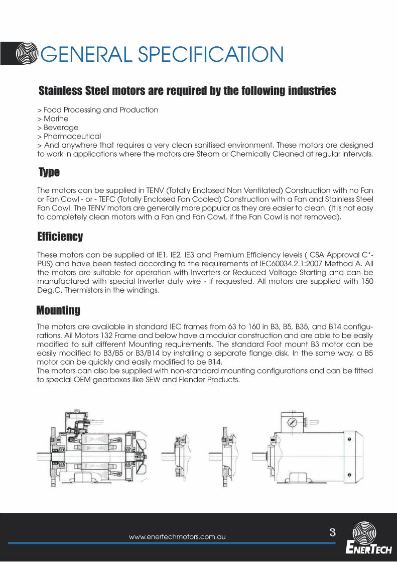
The motors can be supplied in TENV (Totally Enclosed Non Ventilated) Construction with no Fan or Fan Cowl - or - TEFC (Totally Enclosed Fan Cooled) Construction with a Fan and Stainless Steel Fan Cowl. The TENV motors are generally more popular as they are easier to clean. (It is not easy to completely clean motors with a Fan and Fan Cowl, if the Fan Cowl is not removed).
These motors can be supplied at IE1, IE2, IE3 and Premium Efficiency levels ( CSA Approval C*-PUS) and have been tested according to the requirements of IEC60034.2.1:2007 Method A. All the motors are suitable for operation with Inverters or Reduced Voltage Starting and can be manufactured with special Inverter duty wire - if requested. All motors are supplied with 150 Deg.C. Thermistors in the windings.
The motors are available in standard IEC frames from 63 to 160 in B3, B5, B35, and B14 configu-rations. Ail Motors 132 Frame and below have a modular construction and are able to be easily modified to suit different Mounting requirements. The standard Foot mount B3 motor can be easily modified to B3/B5 or B3/B14 by installing a separate flange disk. In the same way, a B5 motor can be quickly and easily modified to be B14.The motors can also be supplied with non-standard mounting configurations and can be fitted to special OEM gearboxes like SEW and Flender Products.
4 www.enertechmotors.com.au
GENERAL SPECIFICATION
I/ INN IL TN T/ TLN T/ TBN
380V
400V
415V
525V
400V380V400V415V440V460V380V415V400V415V440V460V480V380V400V440V415V440V460V480V550V525V550V575V600V
50Hz60Hz60Hz60Hz60Hz60Hz50Hz50Hz60Hz60Hz60Hz60Hz60Hz50Hz*50Hz50Hz60Hz60Hz60Hz60Hz50Hz60Hz60Hz60Hz60Hz
100100105110115120100100100104110115120100100100100105110115100100105110115
100120120120120120100100120120120120120100100100120120120120100120120120120
95989898
100100105
96989898
100100109104
94989898
10095989898
100
110839095
100105
91108
838995
100105
8493
112839095
100110839095
100
10083879196
100100100
83869196
100100100100
83879196
10083879196
11070808595
10090
10870758593
1008493
11270808595
11070808595
11085909398
10390
10885889398
1038493
11285909498
11085909498
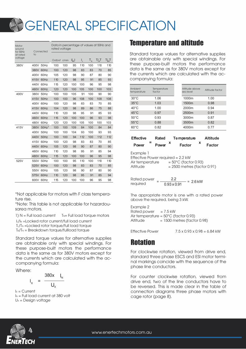
Motorwoundfor 50Hzat ratedvoltage
Data in percentage of values at 50Hz andrated voltage
*Not applicable for motors with F class tempera-ture rise.*Note: This table is not applicable for hazardou-sarea motors.1) N = Full load current TN= Full load torque motors
Where:
IL/IN =Locked rotor current/full load currentTL/TN =Locked rotor torque/full load torqueTB/TN = Breakdown torque/fullload torque
Standard torque values for alternative supplies are obtainable only with special windings. For these purpose-built motors the performance data is the same as for 380V motors except for the currents which are calculated with the ac-companying formula:
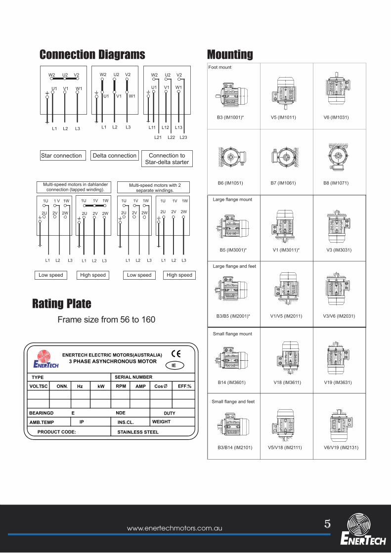
For clockwise rotation, viewed from drive end, standard three phase ESCS and ESI motor termi-nal markings coincide with the sequence of the phase line conductors.
For counter clockwise rotation, viewed from drive end, two of the line conductors have to be reversed. This is made clear in the table of connection diagrams three phase motors with cage rotor (page 8).
Standard torque values for alternative supplies are obtainable only with special windings. For these purpose-built motors the performance data is the same as for 380V motors except for the currents which are calculated with the ac-companying formula:
Example 1Effective Power required = 2.2 kWAir temperature = 50°C (factor 0.93)Altitude = 2500 metres (factor 0.91)
Example 2Rated power = 7.5 kWAir temperature = 50°C (factor 0.93)Altitude = 1500 metres (factor 0.98)
Effective Power 7.5 x 0.93 x 0.98 = 6.84 kW
The appropriate motor is one with a rated power above the required, being 3 kW.
Rated powerrequired
IX = CurrentIN = Full load current at 380 voltUX = Design voltage
Connectedto
Ambienttemperature
Temperaturefactor
Altitude abovesea level
Altitude factor
Output r/min
IX =380x
UX
IN
Temperature and altitude
Rotation
Power = Power x Factor xEffective Rated Temperature Altitude
Factor
30°C 1.06 1000m 1.0035°C 1.03 1500 .9840°C 1.00 2000m 0.9445°C 0.97 2500m 0.9150°C 0.93 3000m 0.8755°C 0.88 3500m 0.8260°C 0.82 4000m 0.77
0.m
=2.2
= 2.6 kW0.93 x 0.91
5www.enertechmotors.com.au
Frame size from 56 to 160
Large flange mount
Small flange mount
Large flange and feet
Small flange and feet
B14 (IM3601) V18 (IM3611) V19 (IM3631)
B3/B14 (IM2101) V5/V18 (IM2111) V6/V19 (IM2131)
=
3 PHASE ASYNCHRONOUS MOTOR
TYPEINS.CL. IP
WEIGHTAMB.TEMP DUTY
BEARING DE NDECONN. Hz kW RPM AMP Cos EFF.%
c
IE1
PRODUCT CODE:
KG
3 PHASE ASYNCHRONOUS MOTOR
TYPEINS.CL. IP
WEIGHTAMB.TEMP DUTY
BEARING DE NDECONN. Hz kW RPM AMP Cos EFF.%
cPRODUCT CODE:
KG
IE 2
Rating Plate
MountingConnection Diagrams
ENERTECH ELECTRIC MOTORS(AUSTRALIA)3 PHASE ASYNCHRONOUS MOTOR
TYPE SERIAL NUMBER
VOLTSC ONN. Hz kW RPM AMP EFF.%
BEARINGD E NDE
AMB.TEMP INS.CL. IP
DUTY WEIGHT
lE2
Cos
PRODUCT CODE: STAINLESS STEEL
6 www.enertechmotors.com.au
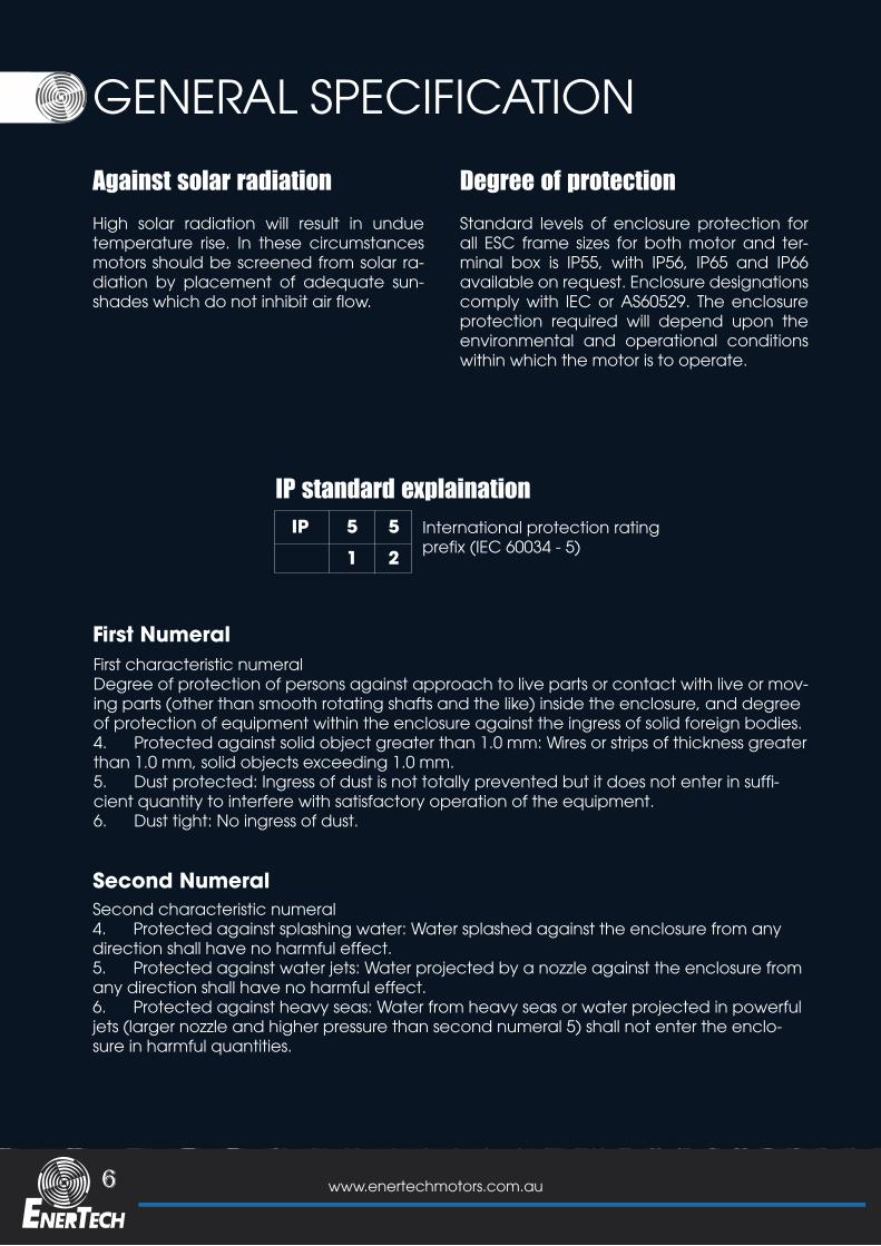
GENERAL SPECIFICATIONAgainst solar radiation High solar radiation will result in undue temperature rise. In these circumstances motors should be screened from solar ra-diation by placement of adequate sun-shades which do not inhibit air flow.
IP standard explaination
First Numeral
Second Numeral
Degree of protectionStandard levels of enclosure protection for all ESC frame sizes for both motor and ter-minal box is IP55, with IP56, IP65 and IP66 available on request. Enclosure designations comply with IEC or AS60529. The enclosure protection required will depend upon the environmental and operational conditions within which the motor is to operate.
International protection rating prefix (IEC 60034 - 5)
First characteristic numeral Degree of protection of persons against approach to live parts or contact with live or mov-ing parts (other than smooth rotating shafts and the like) inside the enclosure, and degree of protection of equipment within the enclosure against the ingress of solid foreign bodies.4. Protected against solid object greater than 1.0 mm: Wires or strips of thickness greater than 1.0 mm, solid objects exceeding 1.0 mm.5. Dust protected: Ingress of dust is not totally prevented but it does not enter in suffi-cient quantity to interfere with satisfactory operation of the equipment.6. Dust tight: No ingress of dust.
Second characteristic numeral4. Protected against splashing water: Water splashed against the enclosure from any direction shall have no harmful effect.5. Protected against water jets: Water projected by a nozzle against the enclosure from any direction shall have no harmful effect.6. Protected against heavy seas: Water from heavy seas or water projected in powerful jets (larger nozzle and higher pressure than second numeral 5) shall not enter the enclo-sure in harmful quantities.
IP 5
1 25
7www.enertechmotors.com.au
Shaft
Electrical design
Voltage and frequency
ESCS - ESI motors have standard shaft extension lengths which provided with standard key, drilled and tapped hole. Non standard shaft extensions are available upon special order, with shaft design outlined on a detailed drawing. Shaft extension run out, concentricity and perpendicularity to face of standard flange mount motors, comply with normal grade tol-erance as specified in IEC 60072-1 and AS1359. Precision grade tolerance is available upon special order.
Standard ESCS and ESI motors are designed for a power supply of three phase 380V, 50Hz. Motors can be manufactured for any supply between 100V and 600 V and frequen-cies other than 50Hz. Standard ESCS and ESI motors wound for a certain voltage at 50Hz can also operate at oth-er voltages at 50Hz and 60Hz without modification, subject to the changes in their data .
As standard, ESCS and ESI motors have the following design and operating parameters. Performance data is based on this standard. Any deviation should be examined and perfor-mance values altered in accordance with the information provided in this section.Three phase, 380V, 50HzAmbient cooling air temperature, 40°CAltitude - 1000m Duty cycle 51 (continuous)Rotatio - Clockwise viewed from drive endConnection - 220 volt Delta/380 volt Star (3kW and below) - 380 volt Delta/660 volt Star (4kW and above)
8 www.enertechmotors.com.au
Duty
Connection
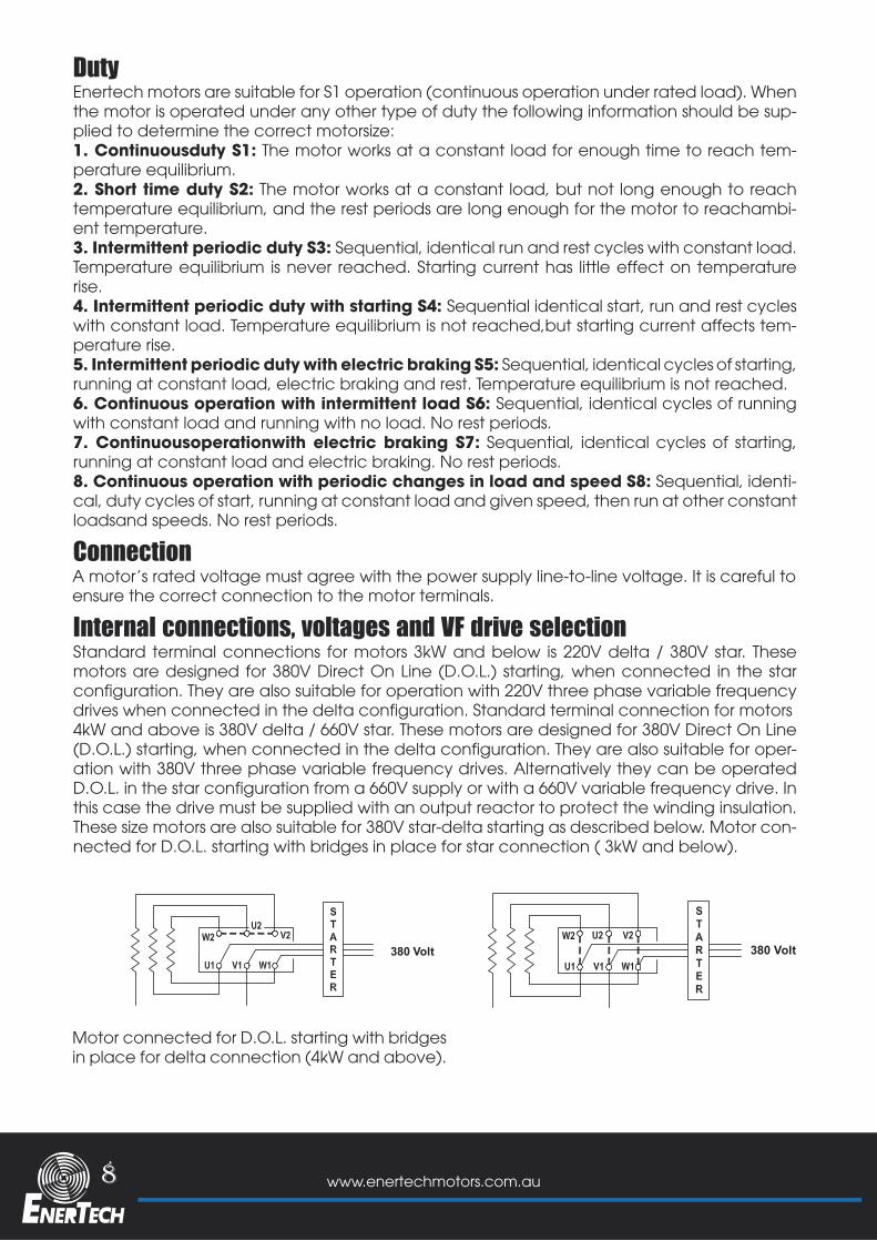
Internal connections, voltages and VF drive selection
Enertech motors are suitable for S1 operation (continuous operation under rated load). When the motor is operated under any other type of duty the following information should be sup-plied to determine the correct motorsize:1. Continuousduty S1: The motor works at a constant load for enough time to reach tem-perature equilibrium.2. Short time duty S2: The motor works at a constant load, but not long enough to reach temperature equilibrium, and the rest periods are long enough for the motor to reachambi-ent temperature.3. Intermittent periodic duty S3: Sequential, identical run and rest cycles with constant load. Temperature equilibrium is never reached. Starting current has little effect on temperature rise.4. Intermittent periodic duty with starting S4: Sequential identical start, run and rest cycles with constant load. Temperature equilibrium is not reached,but starting current affects tem-perature rise.5. Intermittent periodic duty with electric braking S5: Sequential, identical cycles of starting, running at constant load, electric braking and rest. Temperature equilibrium is not reached.6. Continuous operation with intermittent load S6: Sequential, identical cycles of running with constant load and running with no load. No rest periods.7. Continuousoperationwith electric braking S7: Sequential, identical cycles of starting, running at constant load and electric braking. No rest periods.8. Continuous operation with periodic changes in load and speed S8: Sequential, identi-cal, duty cycles of start, running at constant load and given speed, then run at other constant loadsand speeds. No rest periods.
A motor’s rated voltage must agree with the power supply line-to-line voltage. It is careful to ensure the correct connection to the motor terminals.
Motor connected for D.O.L. starting with bridges in place for delta connection (4kW and above).
Standard terminal connections for motors 3kW and below is 220V delta / 380V star. These motors are designed for 380V Direct On Line (D.O.L.) starting, when connected in the star configuration. They are also suitable for operation with 220V three phase variable frequency drives when connected in the delta configuration. Standard terminal connection for motors4kW and above is 380V delta / 660V star. These motors are designed for 380V Direct On Line (D.O.L.) starting, when connected in the delta configuration. They are also suitable for oper-ation with 380V three phase variable frequency drives. Alternatively they can be operated D.O.L. in the star configuration from a 660V supply or with a 660V variable frequency drive. In this case the drive must be supplied with an output reactor to protect the winding insulation. These size motors are also suitable for 380V star-delta starting as described below. Motor con-nected for D.O.L. starting with bridges in place for star connection ( 3kW and below).
380 Volt 380 Volt
9www.enertechmotors.com.au
Starting
EDM Concerns
D.O.L Starter
VVVF
Star - Delta starting
All of the following starter options are available and are the best supplied together with the motor.
Capacitive voltages in the rotor can be gen-erated due to an effect caused by harmonics in the waveform causing voltage discharge to earth through the bearings. This discharge re-sults in etching of the bearing running surfac-es. This effect is known as Electrical Discharge Machining(EDM). It can be controlled with the fitment of appropriate filters to the drive. To futher reduce the effect of EDM, an insulated non drive bearing can be used.
When an electric motor is started by direct connection to the power supply (D.O.L.), it draws a high current, called the ‘starting cur-rent’, which is approximately equal in magni-tude to the locked rotor current IL. As listed in the performance data, locked rotor current can be up to 8 times the rated current IN of the motor. In circumstances where the motor starts under no load or where high starting torque is not required, it is preferable to reduce the starting current by one of the following means.
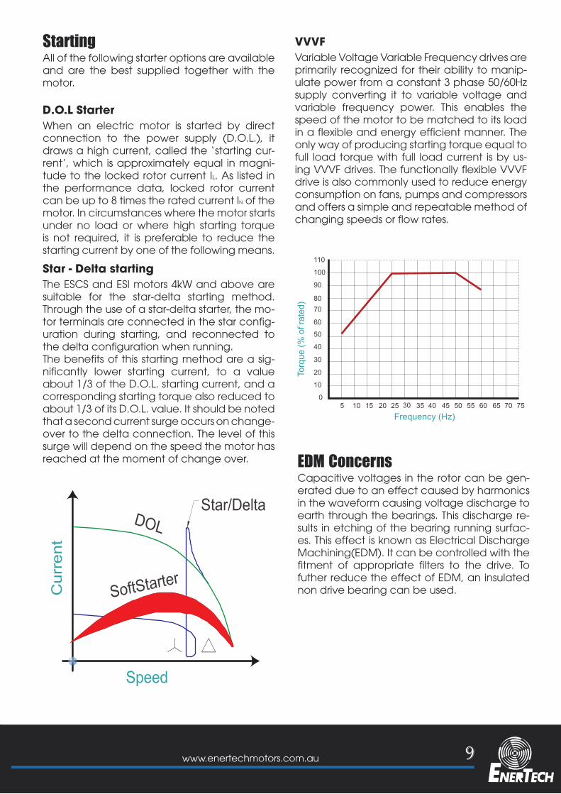
Variable Voltage Variable Frequency drives are primarily recognized for their ability to manip-ulate power from a constant 3 phase 50/60Hz supply converting it to variable voltage and variable frequency power. This enables the speed of the motor to be matched to its load in a flexible and energy efficient manner. The only way of producing starting torque equal to full load torque with full load current is by us-ing VVVF drives. The functionally flexible VVVF drive is also commonly used to reduce energy consumption on fans, pumps and compressors and offers a simple and repeatable method of changing speeds or flow rates.
The ESCS and ESI motors 4kW and above are suitable for the star-delta starting method. Through the use of a star-delta starter, the mo-tor terminals are connected in the star config-uration during starting, and reconnected to the delta configuration when running.The benefits of this starting method are a sig-nificantly lower starting current, to a value about 1/3 of the D.O.L. starting current, and a corresponding starting torque also reduced toabout 1/3 of its D.O.L. value. It should be noted that a second current surge occurs on change-over to the delta connection. The level of this surge will depend on the speed the motor has reached at the moment of change over.
10 www.enertechmotors.com.au
GENERAL SPECIFICATIONInsulation
Speed at partial loads
Current at partial loads
Torque characteristics
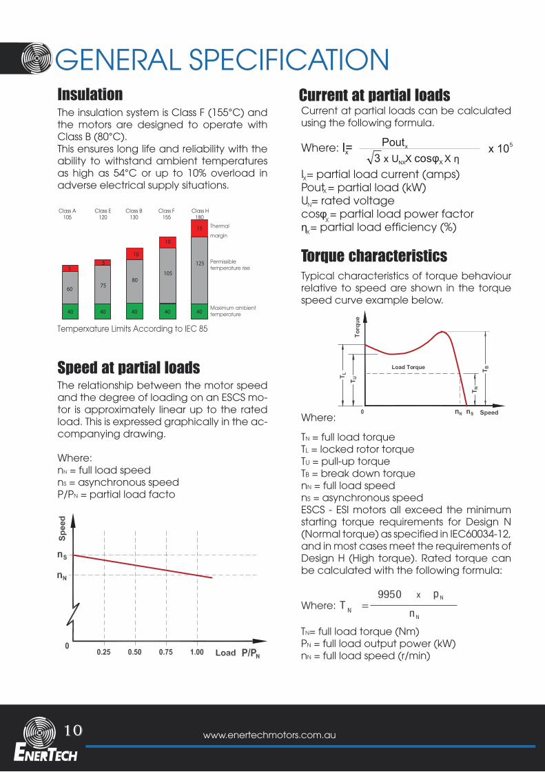
The insulation system is Class F (155°C) and the motors are designed to operate with Class B (80°C). This ensures long life and reliability with the ability to withstand ambient temperatures as high as 54°C or up to 10% overload in adverse electrical supply situations.
Typical characteristics of torque behaviour relative to speed are shown in the torque speed curve example below.
TN = full load torqueTL = locked rotor torqueTU = pull-up torqueTB = break down torquenN = full load speednS = asynchronous speedESCS - ESI motors all exceed the minimum starting torque requirements for Design N (Normal torque) as specified in IEC60034-12, and in most cases meet the requirements of Design H (High torque). Rated torque can be calculated with the following formula:
TN= full load torque (Nm)PN = full load output power (kW)nN = full load speed (r/min)
Where:
Where:
Current at partial loads can be calculated using the following formula.
Where:
I = partial load current (amps)Pout = partial load (kW)U = rated voltagecosφ = partial load power factorη = partial load efficiency (%)
The relationship between the motor speed and the degree of loading on an ESCS mo-tor is approximately linear up to the rated load. This is expressed graphically in the ac-companying drawing.
Where:nN = full load speednS = asynchronous speedP/PN = partial load facto
I=xPoutx x 105
3 x U X NX X
Thermal
margin
Permissibletemperature rise
Maximum ambienttemperature
Temperxature Limits According to IEC 85
40 40 40 40 40
60
55
10
10
15
7580
105
125
Class A105
Class E120
Class B130
Class F155
Class H180
p N
T =N
9950
n N
x
X
X
X
X
N
Load Torque
11www.enertechmotors.com.au
PERFORMANCE DATA
12 www.enertechmotors.com.au
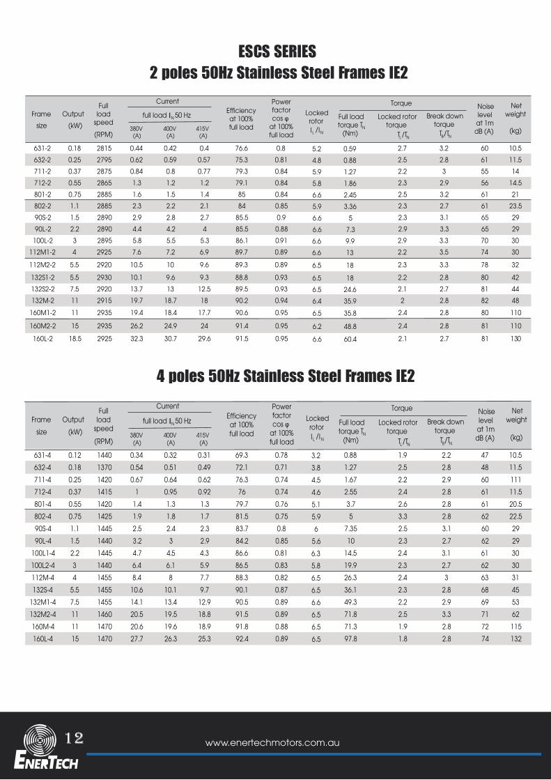
2 poles 50Hz Stainless Steel Frames IE2ESCS SERIES
4 poles 50Hz Stainless Steel Frames IE2
631-2 0.18 2815 0.44 0.42 0.4 76.6 0.8 0.595.2 2.7 3.2 60 10.5632-2 0.25 2795 0.62 0.59 0.57 75.3 0.81 0.884.8 2.5 2.8 61 11.5711-2 0.37 2875 0.84 0.8 0.77 79.3 0.84 1.275.9 2.2 3 55 14712-2 0.55 2865 1.3 1.2 1.2 79.1 0.84 1.865.8 2.3 2.9 56 14.5801-2 0.75 2885 1.6 1.5 1.4 85 0.84 2.456.6 2.5 3.2 61 21802-2 1.1 2885 2.3 2.2 2.1 84 0.85 3.365.9 2.3 2.7 61 23.590S-2 1.5 2890 2.9 2.8 2.7 85.5 0.9 56.6 2.3 3.1 65 2990L-2 2.2 2890 4.4 4.2 4 85.5 0.88 7.36.6 2.9 3.3 65 29
100L-2 3 2895 5.8 5.5 5.3 86.1 0.91 9.96.6 2.9 3.3 70 30112M1-2 4 2925 7.6 7.2 6.9 89.7 0.89 136.6 2.2 3.5 74 30
112M2-2 5.5 2920 10.5 10 9.6 89.3 0.89 186.5 2.3 3.3 78 32
132S1-2 5.5 2930 10.1 9.6 9.3 88.8 0.93 186.5 2.2 2.8 80 42132S2-2 7.5 2920 13.7 13 12.5 89.5 0.93 24.66.5 2.1 2.7 81 44132M-2 11 2915 19.7 18.7 18 90.2 0.94 35.96.4 2 2.8 82 48
160M1-2 11 2935 19.4 18.4 17.7 90.6 0.95 35.86.5 2.4 2.8 80 110
160M2-2 15 2935 26.2 24.9 24 91.4 0.95 48.86.2 2.4 2.8 81 110
160L-2 18.5 2925 32.3 30.7 29.6 91.5 0.95 60.46.6 2.1 2.7 81 130
OutputOutputOutputOutput
Efficiencyat 100%full load
Power factorcos φ
at 100%full load
Noiselevelat 1mdB (A)
Netweight
(kg)
Fullload
speed
Current
380V (A)
400V (A)
415V (A)
full load 50 HzIN
(RPM)
OutputFramesize
Full loadtorque T
(Nm)
Torque Locked
rotor Locked rotortorque
T
Break downtorque
NLL /TN
N TB /TN
/(kW)
631-4 0.12 1440 0.34 0.32 0.31 69.3 0.78 0.883.2 1.9 2.2 47 10.5632-4 0.18 1370 0.54 0.51 0.49 72.1 0.71 1.273.8 2.5 2.8 48 11.5711-4 0.25 1420 0.67 0.64 0.62 76.3 0.74 1.674.5 2.2 2.9 60 111712-4 0.37 1415 1 0.95 0.92 76 0.74 2.554.6 2.4 2.8 61 11.5801-4 0.55 1420 1.4 1.3 1.3 79.7 0.76 3.75.1 2.6 2.8 61 20.5802-4 0.75 1425 1.9 1.8 1.7 81.5 0.75 55.9 3.3 2.8 62 22.590S-4 1.1 1445 2.5 2.4 2.3 83.7 0.8 7.356 2.5 3.1 60 2990L-4 1.5 1440 3.2 3 2.9 84.2 0.85 105.6 2.3 2.7 62 29
100L1-4 2.2 1445 4.7 4.5 4.3 86.6 0.81 14.56.3 2.4 3.1 61 30100L2-4 3 1440 6.4 6.1 5.9 86.5 0.83 19.95.8 2.3 2.7 62 30112M-4 4 1455 8.4 8 7.7 88.3 0.82 26.36.5 2.4 3 63 31132S-4 5.5 1455 10.6 10.1 9.7 90.1 0.87 36.16.5 2.3 2.8 68 45
132M1-4 7.5 1455 14.1 13.4 12.9 90.5 0.89 49.36.6 2.2 2.9 69 53132M2-4 11 1460 20.5 19.5 18.8 91.5 0.89 71.86.5 2.5 3.3 71 62160M-4 11 1470 20.6 19.6 18.9 91.8 0.88 71.36.5 1.9 2.8 72 115160L-4 15 1470 27.7 26.3 25.3 92.4 0.89 97.86.5 1.8 2.8 74 132
Efficiencyat 100%full load
Power factorcos φ
at 100%full load
Noiselevelat 1mdB (A)
Netweight
(kg)
Fullload
speed
Current
380V (A)
400V (A)
415V (A)
full load 50 HzIN
(RPM)
OutputFramesize
Full loadtorque T
(Nm)
Torque Locked
rotor Locked rotortorque
T
Break downtorque
NLL /TN
N TB /TN
/(kW)
13www.enertechmotors.com.au
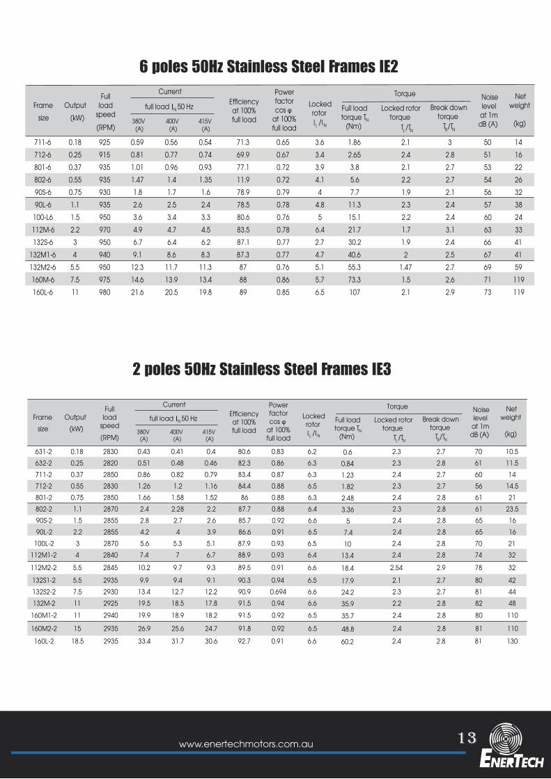
6 poles 50Hz Stainless Steel Frames IE2
2 poles 50Hz Stainless Steel Frames IE3
711-6 0.18 925 0.59 0.56 0.54 71.3 0.65 1.863.6 2.1 3 50 14712-6 0.25 915 0.81 0.77 0.74 69.9 0.67 2.653.4 2.4 2.8 51 16801-6 0.37 935 1.01 0.96 0.93 77.1 0.72 3.83.9 2.1 2.7 53 22802-6 0.55 935 1.47 1.4 1.35 11.9 0.72 5.64.1 2.2 2.7 54 2690S-6 0.75 930 1.8 1.7 1.6 78.9 0.79 7.74 1.9 2.1 56 3290L-6 1.1 935 2.6 2.5 2.4 78.5 0.78 11.34.8 2.3 2.4 57 38
100-L6 1.5 950 3.6 3.4 3.3 80.6 0.76 15.15 2.2 2.4 60 24112M-6 2.2 970 4.9 4.7 4.5 83.5 0.78 21.76.4 1.7 3.1 63 33132S-6 3 950 6.7 6.4 6.2 87.1 0.77 30.22.7 1.9 2.4 66 41
132M1-6 4 940 9.1 8.6 8.3 87.3 0.77 40.64.7 2 2.5 67 41132M2-6 5.5 950 12.3 11.7 11.3 87 0.76 55.35.1 1.47 2.7 69 59160M-6 7.5 975 14.6 13.9 13.4 88 0.86 73.35.7 1.5 2.6 71 119160L-6 11 980 21.6 20.5 19.8 89 0.85 1076.5 2.1 2.9 73 119
Efficiencyat 100%full load
Power factorcos φ
at 100%full load
Noiselevelat 1mdB (A)
Netweight
(kg)
Fullload
speed
Current
380V (A)
400V (A)
415V (A)
full load 50 HzIN
(RPM)
OutputFramesize
Full loadtorque T
(Nm)
Torque Locked
rotor Locked rotortorque
T
Break downtorque
NLL /TN
N TB /TN
/(kW)
631-2 0.18 2830 0.43 0.41 0.4 80.6 0.83 0.66.2 2.3 2.7 70 10.5632-2 0.25 2820 0.51 0.48 0.46 82.3 0.86 0.846.3 2.3 2.8 61 11.5711-2 0.37 2850 0.86 0.82 0.79 83.4 0.87 1.236.3 2.4 2.7 60 14712-2 0.55 2830 1.26 1.2 1.16 84.4 0.88 1.826.5 2.3 2.7 56 14.5801-2 0.75 2850 1.66 1.58 1.52 86 0.88 2.486.3 2.4 2.8 61 21802-2 1.1 2870 2.4 2.28 2.2 87.7 0.88 3.366.4 2.3 2.8 61 23.590S-2 1.5 2855 2.8 2.7 2.6 85.7 0.92 56.6 2.4 2.8 65 1690L-2 2.2 2855 4.2 4 3.9 86.6 0.91 7.46.5 2.4 2.8 65 16
100L-2 3 2870 5.6 5.3 5.1 87.9 0.93 106.5 2.4 2.8 70 21112M1-2 4 2840 7.4 7 6.7 88.9 0.93 13.46.4 2.4 2.8 74 32
112M2-2 5.5 2845 10.2 9.7 9.3 89.5 0.91 18.46.6 2.54 2.9 78 32
132S1-2 5.5 2935 9.9 9.4 9.1 90.3 0.94 17.96.5 2.1 2.7 80 42132S2-2 7.5 2930 13.4 12.7 12.2 90.9 0.694 24.26.6 2.3 2.7 81 44132M-2 11 2925 19.5 18.5 17.8 91.5 0.94 35.96.6 2.2 2.8 82 48
160M1-2 11 2940 19.9 18.9 18.2 91.5 0.92 35.76.5 2.4 2.8 80 110
160M2-2 15 2935 26.9 25.6 24.7 91.8 0.92 48.86.5 2.4 2.8 81 110
160L-2 18.5 2935 33.4 31.7 30.6 92.7 0.91 60.26.6 2.4 2.8 81 130
Efficiencyat 100%full load
Power factorcos φ
at 100%full load
Noiselevelat 1mdB (A)
Netweight
(kg)
Fullload
speed
Current
380V (A)
400V (A)
415V (A)
full load 50 HzIN
(RPM)
OutputFramesize
Full loadtorque T
(Nm)
Torque Locked
rotor Locked rotortorque
T
Break downtorque
NLL /TN
N TB /TN
/(kW)
14 www.enertechmotors.com.au
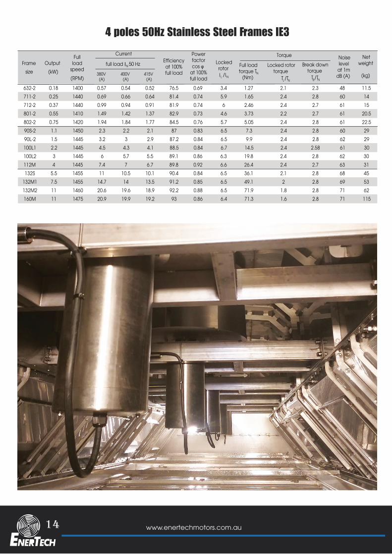
4 poles 50Hz Stainless Steel Frames IE3
632-2 0.18 1400 0.57 0.54 0.52 76.5 0.69 1.273.4 2.1 2.3 48 11.5711-2 0.25 1440 0.69 0.66 0.64 81.4 0.74 1.655.9 2.4 2.8 60 14712-2 0.37 1440 0.99 0.94 0.91 81.9 0.74 2.466 2.4 2.7 61 15801-2 0.55 1410 1.49 1.42 1.37 82.9 0.73 3.734.6 2.2 2.7 61 20.5802-2 0.75 1420 1.94 1.84 1.77 84.5 0.76 5.055.7 2.4 2.8 61 22.590S-2 1.1 1450 2.3 2.2 2.1 87 0.83 7.36.5 2.4 2.8 60 2990L-2 1.5 1445 3.2 3 2.9 87.2 0.84 9.96.5 2.4 2.8 62 29100L1 2.2 1445 4.5 4.3 4.1 88.5 0.84 14.56.7 2.4 2.58 61 30100L2 3 1445 6 5.7 5.5 89.1 0.86 19.86.3 2.4 2.8 62 30112M 4 1445 7.4 7 6.7 89.8 0.92 26.46.6 2.4 2.7 63 31132S 5.5 1455 11 10.5 10.1 90.4 0.84 36.16.5 2.1 2.8 68 45
132M1 7.5 1455 14.7 14 13.5 91.2 0.85 49.16.5 2 2.8 69 53132M2 11 1460 20.6 19.6 18.9 92.2 0.88 71.96.5 1.8 2.8 71 62160M 11 1475 20.9 19.9 19.2 93 0.86 71.36.4 1.6 2.8 71 115
Efficiencyat 100%full load
Power factorcos φ
at 100%full load
Noiselevelat 1mdB (A)
Netweight
(kg)
Fullload
speed
Current
380V (A)
400V (A)
415V (A)
full load 50 HzIN
(RPM)
OutputFramesize
Full loadtorque T
(Nm)
Torque Locked
rotor Locked rotortorque
T
Break downtorque
NLL /TN
N TB /TN
/(kW)
15www.enertechmotors.com.au
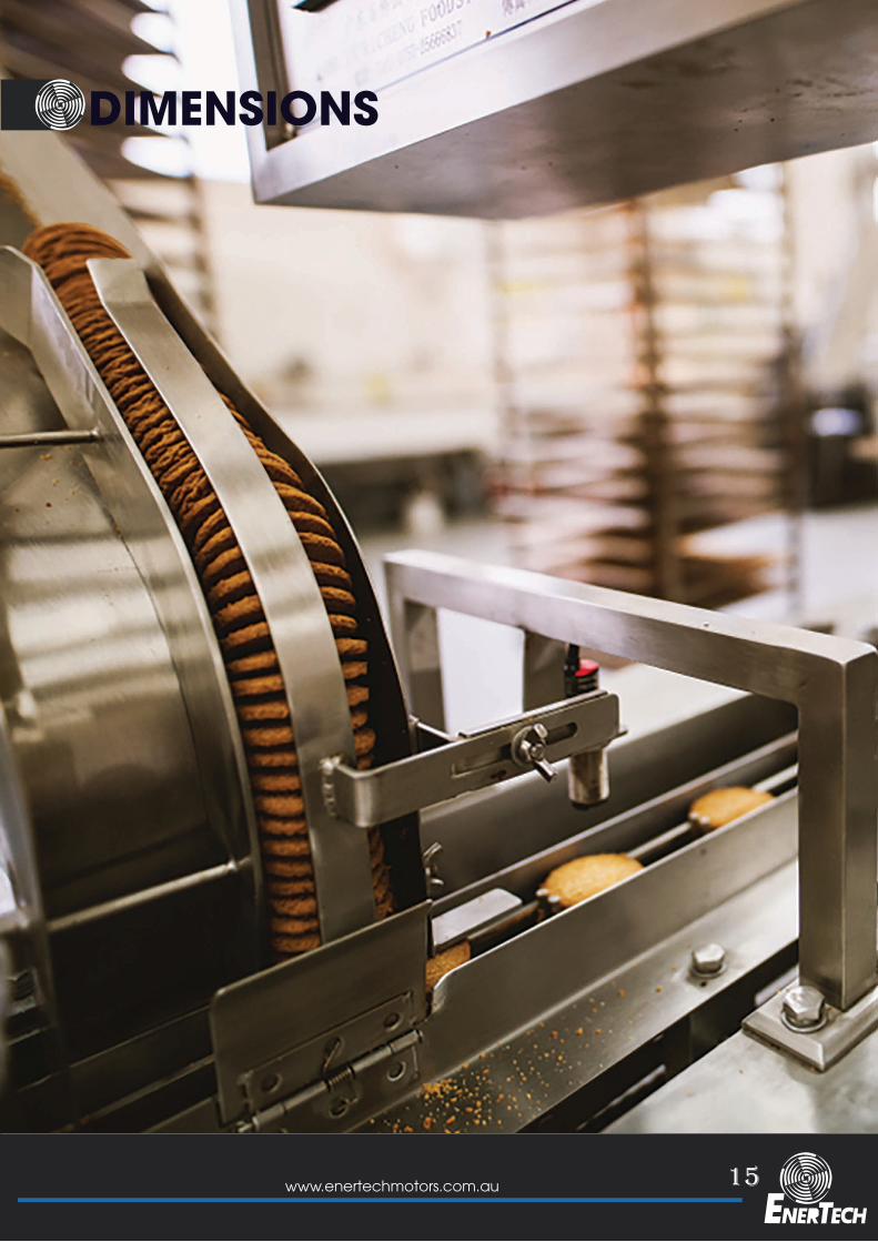
DIMENSIONS
16 www.enertechmotors.com.au
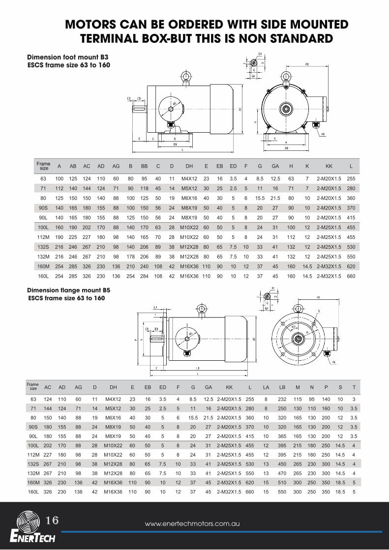
MOTORS CAN BE ORDERED WITH SIDE MOUNTEDTERMINAL BOX-BUT THIS IS NON STANDARD
A AB AC AD AG B BB C D DH E EB ED F G GA H K KK L
63 100 125 124 110 60 80 95 40 11 M4X12 23 16 3.5 4 8.5 12.5 63 7 2-M20X1.5 255
71 112 140 144 124 71 90 118 45 14 M5X12 30 25 2.5 5 11 16 71 7 2-M20X1.5 280
80 125 150 150 140 88 100 125 50 19 M6X16 40 30 5 6 15.5 21.5 80 10 2-M20X1.5 360
90S 140 165 180 155 88 100 150 56 24 M8X19 50 40 5 8 20 27 90 10 2-M20X1.5 370
90L 140 165 180 155 88 125 150 56 24 M8X19 50 40 5 8 20 27 90 10 2-M20X1.5 415
100L 160 190 202 170 88 140 170 63 28 M10X22 60 50 5 8 24 31 100 12 2-M25X1.5 455
112M 190 225 227 180 98 140 165 70 28 M10X22 60 50 5 8 24 31 112 12 2-M25X1.5 455
132S 216 246 267 210 98 140 206 89 38 M12X28 80 65 7.5 10 33 41 132 12 2-M25X1.5 530
132M 216 246 267 210 98 178 206 89 38 M12X28 80 65 7.5 10 33 41 132 12 2-M25X1.5 550
160M 254 285 326 230 136 210 240 108 42 M16X36 110 90 10 12 37 45 160 14.5 2-M32X1.5 620
160L 254 285 326 230 136 254 284 108 42 M16X36 110 90 10 12 37 45 160 14.5 2-M32X1.5 660
Dimension foot mount B3ESCS frame size 63 to 160
Frame size
AC AD AG D DH E EB ED F G GA KK L LA LB M N P S T
63 124 110 60 11 M4X12 23 16 3.5 4 8.5 12.5 2-M20X1.5 255 8 232 115 95 140 10 3
71 144 124 71 14 M5X12 30 25 2.5 5 11 16 2-M20X1.5 280 8 250 130 110 160 10 3.5
80 150 140 88 19 M6X16 40 30 5 6 15.5 21.5 2-M20X1.5 360 10 320 165 130 200 12 3.5
90S 180 155 88 24 M8X19 50 40 5 8 20 27 2-M20X1.5 370 10 320 165 130 200 12 3.5
90L 180 155 88 24 M8X19 50 40 5 8 20 27 2-M20X1.5 415 10 365 165 130 200 12 3.5
100L 202 170 88 28 M10X22 60 50 5 8 24 31 2-M25X1.5 455 12 395 215 180 250 14.5 4
112M 227 180 98 28 M10X22 60 50 5 8 24 31 2-M25X1.5 455 12 395 215 180 250 14.5 4
132S 267 210 98 38 M12X28 80 65 7.5 10 33 41 2-M25X1.5 530 13 450 265 230 300 14.5 4
132M 267 210 98 38 M12X28 80 65 7.5 10 33 41 2-M25X1.5 550 13 470 265 230 300 14.5 4
160M 326 230 136 42 M16X36 110 90 10 12 37 45 2-M32X1.5 620 15 510 300 250 350 18.5 5
160L 326 230 136 42 M16X36 110 90 10 12 37 45 2-M32X1.5 660 15 550 300 250 350 18.5 5
Dimension flange mount B5ESCS frame size 63 to 160
Frame size
17www.enertechmotors.com.au
MOTORS CAN BE ORDERED WITH SIDE MOUNTEDTERMINAL BOX-BUT THIS IS NON STANDARD
A AB AC AD AG B BB C D DH E EB ED F G GA H K KK L LA LB M N P S T
63 100 125 124 110 60 80 95 40 11 M4X12 23 16 3.5 4 8.5 13 63 7 2-M20X1.5 255 8 232 115 95 140 10 3
71 112 140 144 124 71 90 118 45 14 M5X12 30 25 2.5 5 11 16 71 7 2-M20X1.5 280 8 250 130 110 160 10 4
80 125 150 150 140 88 100 125 50 19 M6X16 40 30 5 6 16 22 80 10 2-M20X1.5 360 10 320 165 130 200 12 4
90S 140 165 180 155 88 100 150 56 24 M8X19 50 40 5 8 20 27 90 10 2-M20X1.5 370 10 320 165 130 200 12 4
90L 140 165 180 155 88 125 150 56 24 M8X19 50 40 5 8 20 27 90 10 2-M20X1.5 415 10 365 165 130 200 12 4
100L 160 190 202 170 88 140 170 63 28 M10X22 60 50 5 8 24 31 100 12 2-M25X1.5 455 12 395 215 180 250 15 4
112M 190 225 227 180 98 140 165 70 28 M10X22 60 50 5 8 24 31 112 12 2-M25X1.5 455 12 395 215 180 250 15 4
132S 216 246 267 210 98 140 206 89 38 M12X28 80 65 7.5 10 33 41 132 12 2-M25X1.5 530 13 450 265 230 300 15 4
132M 216 246 267 210 98 178 206 89 38 M12X28 80 65 7.5 10 33 41 132 12 2-M25X1.5 550 13 470 265 230 300 15 4
160M 254 285 326 230 136 210 240 108 42 M16X36 110 90 10 12 37 45 160 14.5 2-M32X1.5 620 15 510 300 250 350 19 5
160L 254 285 326 230 136 254 284 108 42 M16X36 110 90 10 12 37 45 160 14.5 2-M32X1.5 660 15 550 300 250 350 19 5
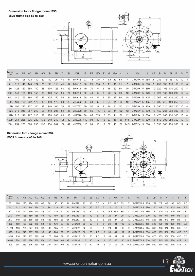
Dimension foot - flange mount B35 ESCS frame size 63 to 160
Frame size
A AB AC AD AG B BB C D DH E EB ED F G GA H K KK L LB M N P S T
63 100 125 124 110 60 80 95 40 11 M4X12 23 16 3.5 4 8.5 12.5 63 7 2-M20X1.5 255 232 75 60 90 M5 2.5
71 112 140 144 124 71 90 118 45 14 M5X12 30 25 2.5 5 11 16 71 7 2-M20X1.5 280 250 85 70 105 M6 2.5
80 125 150 150 140 88 100 125 50 19 M6X16 40 30 5 6 15.5 21.5 80 10 2-M20X1.5 360 320 100 80 120 M6 3
90S 140 165 180 155 88 100 150 56 24 M8X19 50 40 5 8 20 27 90 10 2-M20X1.5 370 320 115 95 140 M8 3
90L 140 165 180 155 88 125 150 56 24 M8X19 50 40 5 8 20 27 90 10 2-M20X1.5 415 365 115 95 140 M8 3
100L 160 190 202 170 88 140 170 63 28 M10X22 60 50 5 8 24 31 100 12 2-M25X1.5 455 395 130 110 160 M8 3.5
112M 190 225 227 180 98 140 165 70 28 M10X22 60 50 5 8 24 31 112 12 2-M25X1.5 455 395 130 110 160 M8 3.5
132S 216 246 267 210 98 140 206 89 38 M12X28 80 65 7.5 10 33 41 132 12 2-M25X1.5 530 450 165 130 200 M10 3.5
132M 216 246 267 210 98 178 206 89 38 M12X28 80 65 7.5 10 33 41 132 12 2-M25X1.5 550 470 165 130 200 M10 3.5
160M 254 285 326 230 136 210 240 108 42 M16X36 110 90 10 12 37 45 160 14.5 2-M32X1.5 620 510 215 180 250 M12 4
160L 254 285 326 230 136 254 284 108 42 M16X36 110 90 10 12 37 45 160 14.5 2-M32X1.5 660 550 215 180 250 M12 4
ESCS frame size 63 to 160 Dimension foot - flange mount B34
Frame size
18 www.enertechmotors.com.au
AC AD AG D DH E EB ED F G GA KK L LB M N P S T
63 124 110 60 11 M4X12 23 16 3.5 4 8.5 12.5 2-M20X1.5 255 232 75 60 90 M5 2.5
71 144 124 71 14 M5X12 30 25 2.5 5 11 16 2-M20X1.5 280 250 85 70 105 M6 2.5
80 150 140 88 19 M6X16 40 30 5 6 15.5 21.5 2-M20X1.5 360 320 100 80 120 M6 3
90S 180 155 88 24 M8X19 50 40 5 8 20 27 2-M20X1.5 370 320 115 95 140 M8 3
90L 180 155 88 24 M8X19 50 40 5 8 20 27 2-M20X1.5 415 365 115 95 140 M8 3
100L 202 170 88 28 M10X22 60 50 5 8 24 31 2-M25X1.5 455 395 130 110 160 M8 3.5
112M 227 180 98 28 M10X22 60 50 5 8 24 31 2-M25X1.5 455 395 130 110 160 M8 3.5
132S 267 210 98 38 M12X28 80 65 7.5 10 33 41 2-M25X1.5 530 450 165 130 200 M10 3.5
132M 267 210 98 38 M12X28 80 65 7.5 10 33 41 2-M25X1.5 550 470 165 130 200 M10 3.5
160M 326 230 136 42 M16X36 110 90 10 12 37 45 2-M32X1.5 620 510 215 180 250 M12 4
160L 326 230 136 42 M16X36 110 90 10 12 37 45 2-M32X1.5 660 550 215 180 250 M12 4
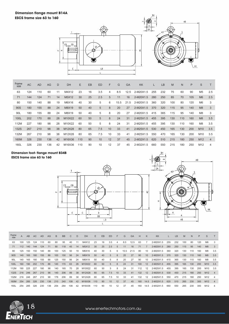
Dimension flange mount B14AESCS frame size 63 to 160
Frame size
A AB AC AD AG B BB C D DH E EB ED F G GA H K KK L LB M N P S T
63 100 125 124 110 60 80 95 40 11 M4X12 23 16 3.5 4 8.5 12.5 63 7 2-M20X1.5 255 232 100 80 120 M6 3
71 112 140 144 124 71 90 118 45 14 M5X12 30 25 2.5 5 11 16 71 7 2-M20X1.5 280 250 115 95 140 M8 3
80 125 150 150 140 88 100 125 50 19 M6X16 40 30 5 6 15.5 21.5 80 10 2-M20X1.5 360 320 130 110 160 M8 3.5
90S 140 165 180 155 88 100 150 56 24 M8X19 50 40 5 8 20 27 90 10 2-M20X1.5 370 320 130 110 160 M8 3.5
90L 140 165 180 155 88 125 150 56 24 M8X19 50 40 5 8 20 27 90 10 2-M20X1.5 415 365 130 110 160 M8 3.5
100L 160 190 202 170 88 140 170 63 28 M10X22 60 50 5 8 24 31 100 12 2-M25X1.5 455 395 165 130 200 M10 3.5
112M 190 225 227 180 98 140 165 70 28 M10X22 60 50 5 8 24 31 112 12 2-M25X1.5 455 395 165 130 200 M10 3.5
132S 216 246 267 210 98 140 206 89 38 M12X28 80 65 7.5 10 33 41 132 12 2-M25X1.5 530 450 215 180 250 M12 4
132M 216 246 267 210 98 178 206 89 38 M12X28 80 65 7.5 10 33 41 132 12 2-M25X1.5 550 470 215 180 250 M12 4
160M 254 285 326 230 136 210 240 108 42 M16X36 110 90 10 12 37 45 160 14.5 2-M32X1.5 620 510 265 230 300 M12 4
160L 254 285 326 230 136 254 284 108 42 M16X36 110 90 10 12 37 45 160 14.5 2-M32X1.5 660 550 265 230 300 M12 4
Frame size
Dimension foot- flange mount B34BESCS frame size 63 to 160
19www.enertechmotors.com.au
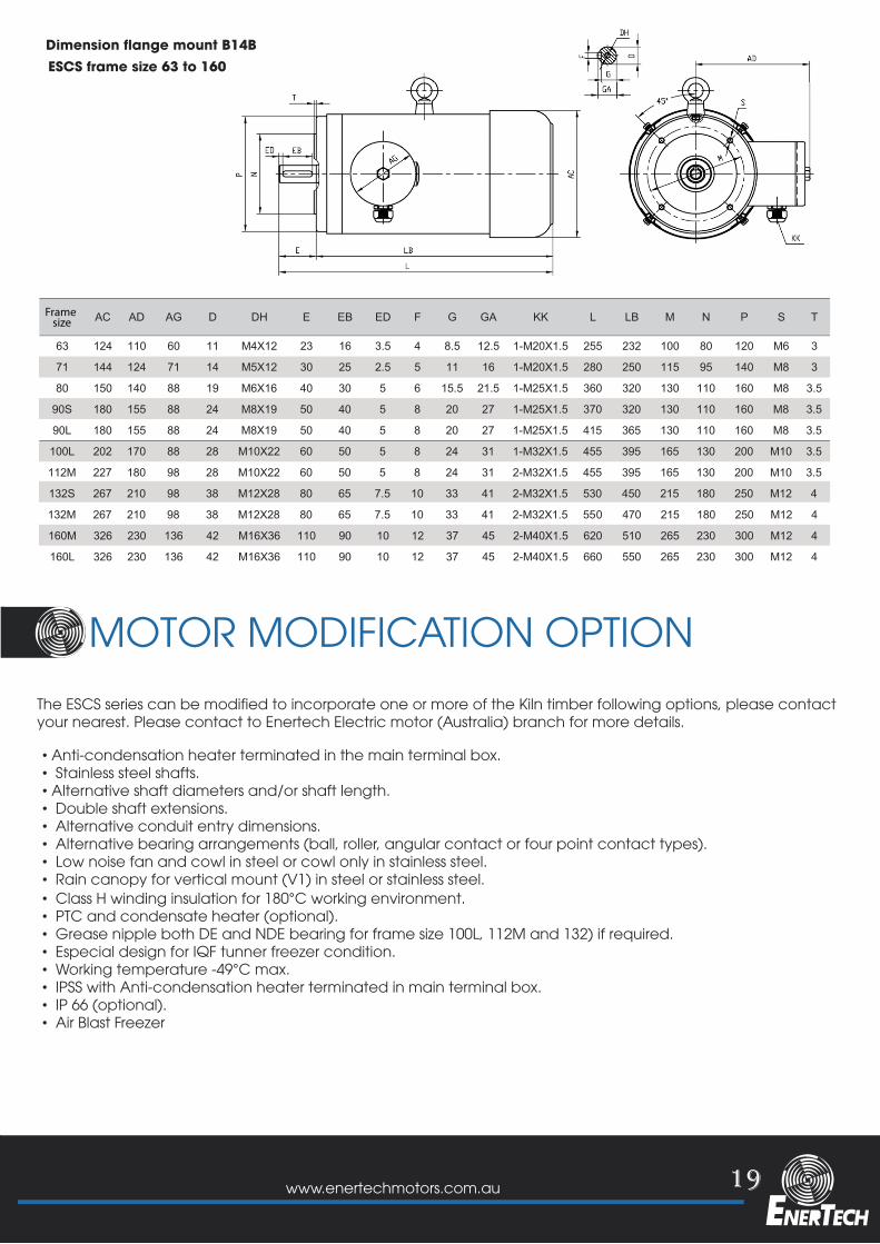
AC AD AG D DH E EB ED F G GA KK L LB M N P S T
63 124 110 60 11 M4X12 23 16 3.5 4 8.5 12.5 1-M20X1.5 255 232 100 80 120 M6 3
71 144 124 71 14 M5X12 30 25 2.5 5 11 16 1-M20X1.5 280 250 115 95 140 M8 3
80 150 140 88 19 M6X16 40 30 5 6 15.5 21.5 1-M25X1.5 360 320 130 110 160 M8 3.5
90S 180 155 88 24 M8X19 50 40 5 8 20 27 1-M25X1.5 370 320 130 110 160 M8 3.5
90L 180 155 88 24 M8X19 50 40 5 8 20 27 1-M25X1.5 415 365 130 110 160 M8 3.5
100L 202 170 88 28 M10X22 60 50 5 8 24 31 1-M32X1.5 455 395 165 130 200 M10 3.5
112M 227 180 98 28 M10X22 60 50 5 8 24 31 2-M32X1.5 455 395 165 130 200 M10 3.5
132S 267 210 98 38 M12X28 80 65 7.5 10 33 41 2-M32X1.5 530 450 215 180 250 M12 4
132M 267 210 98 38 M12X28 80 65 7.5 10 33 41 2-M32X1.5 550 470 215 180 250 M12 4
160M 326 230 136 42 M16X36 110 90 10 12 37 45 2-M40X1.5 620 510 265 230 300 M12 4
160L 326 230 136 42 M16X36 110 90 10 12 37 45 2-M40X1.5 660 550 265 230 300 M12 4
Dimension flange mount B14BESCS frame size 63 to 160
Frame size
MOTOR MODIFICATION OPTIONThe ESCS series can be modified to incorporate one or more of the Kiln timber following options, please contact your nearest. Please contact to Enertech Electric motor (Australia) branch for more details.
• Anti-condensation heater terminated in the main terminal box.• Stainless steel shafts.• Alternative shaft diameters and/or shaft length.• Double shaft extensions.• Alternative conduit entry dimensions.• Alternative bearing arrangements (ball, roller, angular contact or four point contact types).• Low noise fan and cowl in steel or cowl only in stainless steel.• Rain canopy for vertical mount (V1) in steel or stainless steel.• Class H winding insulation for 180°C working environment.• PTC and condensate heater (optional).• Grease nipple both DE and NDE bearing for frame size 100L, 112M and 132) if required. • Especial design for IQF tunner freezer condition.• Working temperature -49°C max.• IPSS with Anti-condensation heater terminated in main terminal box.• IP 66 (optional).• Air Blast Freezer
20 www.enertechmotors.com.au
STAINLESS STEEL CASTING FORFREEZER AIR COOLER
STAINLESS STEEL CASTING FORFREEZER AIR COOLER
21www.enertechmotors.com.au
22 www.enertechmotors.com.au
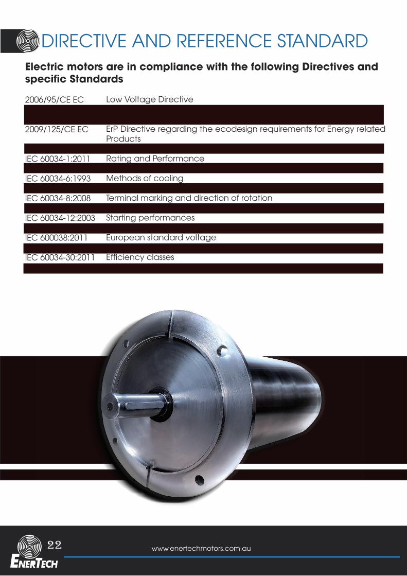
DIRECTIVE AND REFERENCE STANDARDElectric motors are in compliance with the following Directives and specific Standards
2006/95/CE EC 2011/65/EC EC
2009/125/CE EC
640/2009/CE ECIEC 60034-1:2011IEC 60034-5:2001IEC 60034-6:1993IEC 60034-7:1993IEC 60034-8:2008 IEC 60034-9:2006 IEC 60034-12:2003IEC 60034-14:2004IEC 600038:2011 IEC 60072-1:1991 IEC 60034-30:2011 IEC 60034-2-1:2011
Low Voltage DirectiveRoHS Directive regarding the Restriction ofHazardous Substances in electrical and electronic equipmentsErP Directive regarding the ecodesign requirements for Energy related ProductsRegulation regarding the ecodesign requirements for electric motorsRating and PerformanceDegrees of ProtectionMethods of coolingTypes of construction, mounting arrangementsTerminal marking and direction of rotationNoise limitsStarting performancesMechanical vibrationsEuropean standard voltageOutput dimensions and tolerancesEfficiency classesEfficiency measurement methods
23www.enertechmotors.com.au
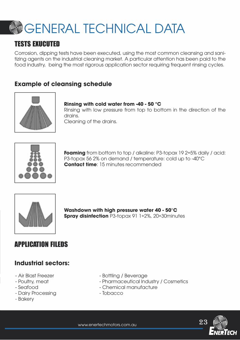
DIRECTIVE AND REFERENCE STANDARD GENERAL TECHNICAL DATATESTS EXUCUTED
APPLICATION FILEDS
Example of cleansing schedule
Industrial sectors:
Corrosion, dipping tests have been executed, using the most common cleansing and sani-tizing agents on the industrial cleaning market. A particular attention has been paid to the food industry, being the most rigorous application sector requiring frequent rinsing cycles.
- Air Blast Freezer- Poultry, meat- Seafood- Dairy Processing- Bakery
- Bottling / Beverage- Pharmaceutical Industry / Cosmetics- Chemical manufacture- Tobacco
Rinsing with cold water from -40 - 50 °CRinsing with low pressure from top to bottom in the direction of the drains.Cleaning of the drains.
Foaming from bottom to top / alkaline: P3-topax 19 2÷5% daily / acid: P3-topax 56 2% on demand / temperature: cold up to -40°CContact time: 15 minutes recommended
Washdown with high pressure water 40 - 50°CSpray disinfection P3-topax 91 1÷2%, 20÷30minutes
24 www.enertechmotors.com.au
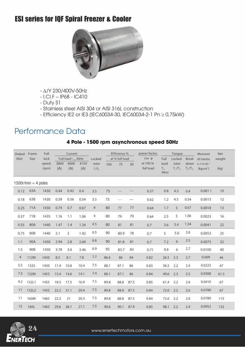
ESI series for IQF Spiral Freezer & Cooler
4 Pole - 1500 rpm asynchronous speed 50Hz
Performance Data
1500r/min = 4 poles
4
5.5
7.5
9.2
11
11
15
112M
132S
132M
132L1
132L2
160M
160L
1450
1450
1455
1455
1455
1465
1465
8.5
11.4
15.4
18.5
22.2
22.2
29.6
8.1
10.8
14.6
17.5
21.1
21
28.1
7.8
10.4
14.1
16.9
20.4
20.3
27.1
0.4
0.54
0.67
1.06
1.34
2.6
2.5
2.7
3.5
3.5
4
4
4.5
6.5
6.6
6.9
7.7
7.5
7.4
7.5
7.5
7.5
7.5
75
75
80
80
80
90
90
95
86.6
88.1
88.1
89.8
89.8
89.8
90.6
86
87.1
87.1
88.8
88.8
88.8
90.1
84
86
86
87.5
87.5
87.5
87.9
0.82
0.83
0.84
0.85
0.84
0.84
0.85
26.5
36.5
49.6
61.4
72.0
72.0
98.1
2.3
2.2
2.3
2.2
2.2
2.2
2.2
2.7
2.4
2.5
2.6
2.6
2.6
2.4
0.009
0.0223
0.0308
0.0410
0.0780
0.0780
0.0952
46
47
61.5
67
67
115
132
- ∆/Y 230/400V-50Hz - I.Cl.F – IP68 - IC410 - Duty S1- Stainless steel AISI 304 or AISI 316L construction- Efficiency IE2 or IE3 (IEC60034-30, IEC60034-2-1 Pn ≥ 0,75kW)
25www.enertechmotors.com.au
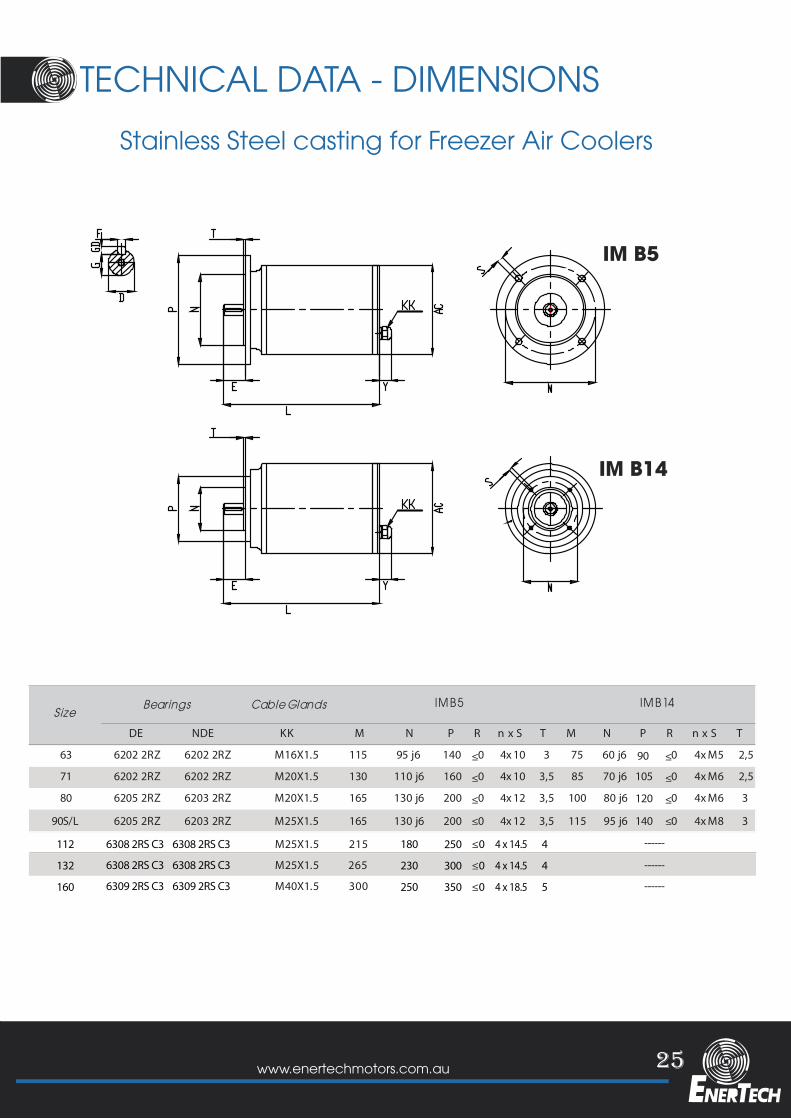
TECHNICAL DATA - DIMENSIONS
IM B5
IM B14
SizeM N P R n x S T M N P R n x S T
63 115 95 j6 140 ≤0 4x 10 3 75 60 j6 ≤0 4x M5 2,5
71 130 110 j6 160 ≤0 4x 10 3,5 85 70 j6 ≤0 4x M6 2,5
80 165 130 j6 200 ≤0 4x 12 3,5 100 80 j6 ≤0 4x M6 3
90S/L 165 130 j6 200 ≤0 4x 12 3,5 115 95 j6 ≤0 4x M8 3
6205 2RZ 6203 2RZ M20X1.5
6205 2RZ 6203 2RZ M25X1.5
6202 2RZ 6202 2RZ M16X1.5
6202 2RZ 6202 2RZ M20X1.5
DE NDE KK
41B MI5B MIBearings Cable Glands
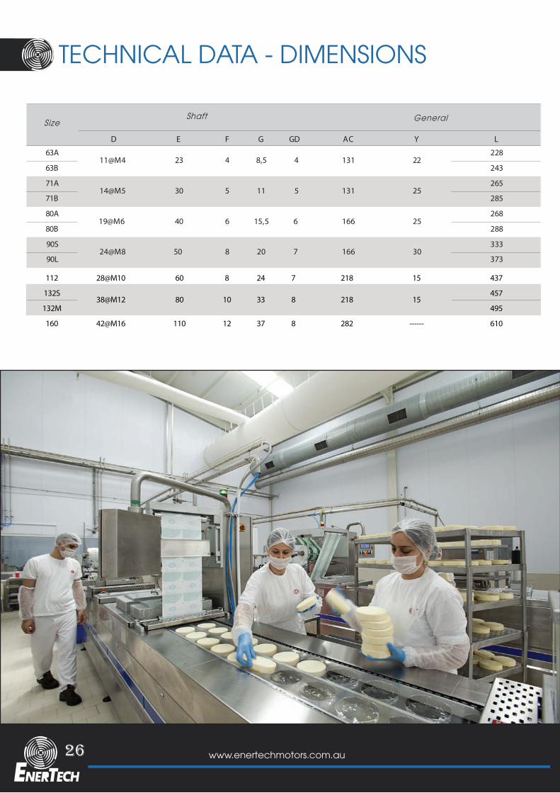
Size
F G GD
63A
63B
71A
71B
80A
80B
90S
90L
224 8,5 4
Y
5
6
8
166
166
11 5
15,5
Shaft General
AC
268
288
333
373
D
11@M4
14@M5
19@M6
E
23
30
40
131
131
24@M8 50
L
228
243
265
285
7
6
20
25
25
30
90
105
120
140
180
230
250
4
4
5
112
132
160
112
132S
132M
160
60
110
8
12
24
37
7
8
218
282
15
------
437
457
495
610
28@M10
42@M16
250
300
350
4 x 14.5
4 x 14.5
4 x 18.5
≤0
≤0
≤0
6308 2RS C3
6308 2RS C3
6309 2RS C3
38@M12 80 10 33 8 218 15
6308 2RS C3 M25X1.5 215
265
300
M25X1.5
M40X1.5
6308 2RS C3
6309 2RS C3
------
------
------
Stainless Steel casting for Freezer Air Coolers
26 www.enertechmotors.com.au
TECHNICAL DATA - DIMENSIONS
SizeM N P R n x S T M N P R n x S T
63 115 95 j6 140 ≤0 4x 10 3 75 60 j6 ≤0 4x M5 2,5
71 130 110 j6 160 ≤0 4x 10 3,5 85 70 j6 ≤0 4x M6 2,5
80 165 130 j6 200 ≤0 4x 12 3,5 100 80 j6 ≤0 4x M6 3
90S/L 165 130 j6 200 ≤0 4x 12 3,5 115 95 j6 ≤0 4x M8 3
6205 2RZ 6203 2RZ M20X1.5
6205 2RZ 6203 2RZ M25X1.5
6202 2RZ 6202 2RZ M16X1.5
6202 2RZ 6202 2RZ M20X1.5
DE NDE KK
41B MI5B MIBearings Cable Glands
Size
F G GD
63A
63B
71A
71B
80A
80B
90S
90L
224 8,5 4
Y
5
6
8
166
166
11 5
15,5
Shaft General
AC
268
288
333
373
D
11@M4
14@M5
19@M6
E
23
30
40
131
131
24@M8 50
L
228
243
265
285
7
6
20
25
25
30
90
105
120
140
180
230
250
4
4
5
112
132
160
112
132S
132M
160
60
110
8
12
24
37
7
8
218
282
15
------
437
457
495
610
28@M10
42@M16
250
300
350
4 x 14.5
4 x 14.5
4 x 18.5
≤0
≤0
≤0
6308 2RS C3
6308 2RS C3
6309 2RS C3
38@M12 80 10 33 8 218 15
6308 2RS C3 M25X1.5 215
265
300
M25X1.5
M40X1.5
6308 2RS C3
6309 2RS C3
------
------
------
27www.enertechmotors.com.au
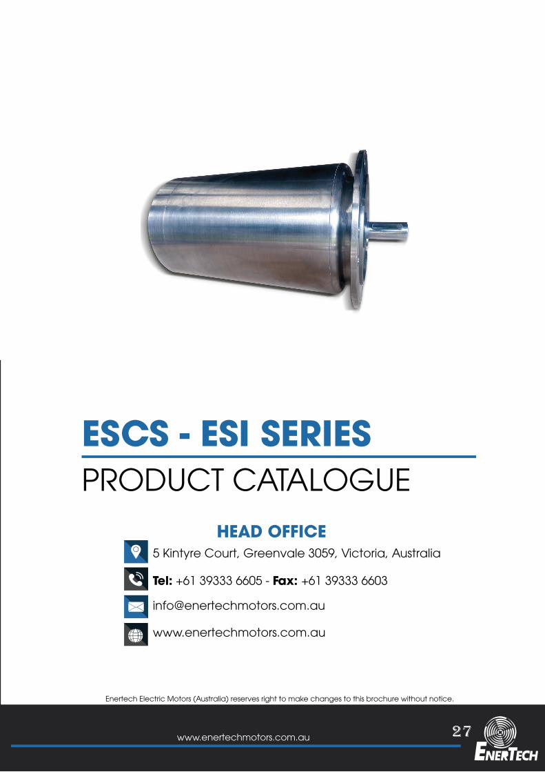
ESCS - ESI SERIES
HEAD OFFICE
PRODUCT CATALOGUE
5 Kintyre Court, Greenvale 3059, Victoria, Australia
www.enertechmotors.com.au
Enertech Electric Motors (Australia) reserves right to make changes to this brochure without notice.
Tel: +61 39333 6605 - Fax: +61 39333 6603

HEAD OFFICE5 Kintyre Court, Greenvale 3059, Victoria, Australia
www.enertechmotors.com.au
Tel: +61 39333 6605 - Fax: +61 39333 6603