escodisc couplings - transmissioner | jens-s · special executions available ... api 610 yes yes...
TRANSCRIPT

DLC - DMU - DPU
esco
escodisc couplings

escodiscFLEXIBLE DISC TYPE COUPLINGS
IndexIntroduction ................................................................................ 1Why Escodisc? ....................................................................... 2Standard Escodisc Range ........................................................ 3Special executions available ................................................. 4How to select the right Escodisc type ................................ 5How to select the right Escodisc size ..............................6-7Escodisc DLC SERIES ................................................................ 9Escodisc DLC quick selection table ....................................10Escodisc DLC .......................................................................... 11Escodisc DLCC ..........................................................................12Escodisc DLFR ...........................................................................13 Escodisc DMU SERIES ............................................................15Escodisc DMU quick selection table ..................................16Escodisc DMU ................................................................. 17 - 18Escodisc DMUCC .....................................................................19Escodisc DMUFR ......................................................................20Escodisc DPU SERIES ..............................................................21Escodisc DPU quick selection table ....................................22Escodisc DPUSS .......................................................................23DPU equivalent chart .............................................................24Shaft connection ................................................................... 26Balancing of Escodisc couplings ....................................... 27 Ecodisc references ............................................................... 28Installation & Maintenance serie DL ..........................29-31Installation & Maintenance serie DMU .....................33-35Installation & Maintenance serie DPU .......................37-39Installation & Maintenance serie DMUCC ................41-43Specific Protective Measures .....................................44
In a world where efficiency, extended life, less maintenance and
reduced life cycle costs are becoming more and more important,
the role of the coupling (the connection between two machines)
and its influence cannot be underestimated. This is why designers
and manufacturers of rotating machines are asking for larger tor-
ques, better misalignment capacities, excellent production quality,
lower weights and significantly reduced reaction forces.
Disc type couplings offer the user numerous advantages: they are
maintenance free, they have very low reaction forces in case of
misalignment, and thanks to their high degree of inherent balance,
create no vibrations which might cause damage to components
such as mechanical seals, bearings, etc...
The Esco engineers have succeeded in optimising the design of the disc type coupling in order to reduce the reaction forces to
an absolute minimum level. Also phenomena such as "fretting
corrosion" and buckling, that can significantly limit the life of
a disc type coupling, have ben eliminated. Escodisc couplings
have been developed, tested and manufactured for infinite life, maintenance free use, reduced assembly costs and increased machine efficiency.
Series DLCTorque: up to 1600 Nm
Bore: up to 105 mm
Series DMUTorque: up to 260000 Nm
Bore: up to 370 mm
Series DPUTorque: up to 23100 Nm
Bore: up to 220 mm
Printed in Belgium 03/2001 1

escodisc
Why Escodisc ?
High Torque and Misalignment capacityThanks to the optimised disc shape and thickness (which could be obtained by finite element analysis and laser cutting), the optimised number of bolts and the standard use of 12.9 quality bolts, Escodisc couplings have a high torque and misalignment capacity combined with reduced reaction forces on connected equipment (bearings, mechanical seals...).
Infinite lifeAll Escodisc couplings have been calculated, designed and tested for infinite life. This is possible thanks to the use of discs in AISI 301 stainless steel with special surface treatment, the standard use of fillers between the discs to eliminate fretting corrosion and the use of high Safety margin on catalogue values.
No BucklingIn order to guarantee perfect centring of the spacer under all working condition (very important for long DBSE applications) and well controlled stresses in the disc pack, Escodisc couplings have been calculated and tested to have no buckling up to the peak torque. This results in trouble free operation, maximum efficiency and reduced risk for disc failure.
Flexible Spacer DesignThanks to the unique design of the Escodisc spacer (flanges bolted to the intermediate tube section - see catalogue drawings DMU/DPU), its length is easily adaptable to cus-tomer requirements. Therefore quick delivery (even for non-standard DBSE) is possible and customer stock can be reduced to a minimum level.
Suitable for extreme temperatures and corrosive environmentEscodisc couplings can operate at temperatures as high as 270°C and as low as -20°C, (lower or higher temperature level on request). Furthermore, thanks to the use of stainless steel discs, the standard use of Dacromet protection for the hardware and a special surface treatment, Escodisc couplings are ideal for use in a corrosive environment.
Easy assembly and disassemblyTo save cost at the assembly and the disassembly stages, the design of all Escodisc couplings has been optimised (factory assembled disc pack or transmission unit, ship-ping screws...).
Torque transmission in case of disc pack failureIn the unlikely event of a disc pack failure, the Escodisc couplings have been designed in such a way that torque transmissions remains guaranteed for a limited time (trough the bolts). This system furthermore keeps the spacer well centred and works as an anti-fly system through which optimum user safety can be assured.
ADVANTAGES
Printed in Belgium 08/20062

escodisc
DMUFR A118 DMUCC A117
DLCC A111
DLFR A112
DLC A110
DPUSL A121
DPUSS A121
DPULL A121DMU A115 & 116
Printed in Belgium 11/2007 A101 E
Single disc
Close coupled Flex-rigid
Standard Close coupled
Flex-rigid
Pre-assembled disc pack
AVAILABILITIES
S Hub L Hub
S Hub S Hub
L Hub L Hub
Unitized multi discs
SERIES DL - DMU - DPU
3

escodiscSERIES DL - DMU - DPU
Special Execution Available (on request)
DPUSSNS - Non Sparking Execution
DMULE - Limited End Float
DPUSSSP - Shear Pin Overload Protection
DPSSET - Esco Torque Overload Protection (adjustable)
DPUSSOS - Overload Spacer
DPUSSV - Vertical Execution
DMUIN - Electrically Insulated
DMUCCBD - With Integrated Brake Disc
DPUSSCP - With Composite Spacer
DPUEDSS - Extended Diameter
A102 E Dimensions in mm without engagement — Printed in Belgium 03/20014

escodisc
Printed in Belgium 03/2001 A103 E
HOW TO SELECT THE RIGHT COUPLING SIZE 1. BASED ON APPLICATION DATA Depending on torque, speed, distance between shaft ends and the shaft sizes of the two machines to be connected, a first selection
can be made. DLC couplings are limited in torque and bore capacity so for medium to high torque application DMU or DPU series have to be used. For torques > 23100 Nm, DMU is preferred. High Speed applications are, thanks to its concept, best covered by the DPU series. For short DBSE application, DLCC or DMUCC can be selected while for long DBSE application (DBSE > 1000 mm) requiring balancing, escodisc DMU or DPU have to be used. In the below table an overview of the coupling characteristics are given for quick selection.
2. BASED ON SPECIFIC APPLICATION REQUIREMENTS Specific application requirements can also determine the escodisc type to be used. These requirements might be balancing, conformity
to API specifications, non-sparking execution, special materials, assembly, available space etc... In the below table, an overview of the conformity of the DLC/DMU/DPU to specific application requirements can be found.
3. BASED ON COMMERCIAL REQUIREMENTS
4. BASED ON CUSTOMER STANDARDISATION/PREFERENCE
SELECTION
DLC DLCC DMU DMUCC DPU
Torque Capacity (1) 1600 1600 260000 19800 23100
Bore Capacity 105 85 370 170 220
Balancing (2) Q 2,5 Q 2,5
Short DBSE (<50 mm) Yes Yes
Long DBSE (>1000 mm) Yes Yes
Large Hub Yes
Non Sparking Optional Optional
High Speed Applications (>3000 rpm) Optional
API 610 Yes Yes
API 671 Optional
Electrical Insulation Optional Optional Optional
Limited End Float Optional Optional
Shear Pin Overload Protection Optional
Esco Torque Overload Protection Optional
Overload Spacer Optional Optional
Vertical Execution Optional
Remarks: (1) Indicated Torque capacity is for standard range. Larger sizes are available on request.
(2) Indicated balance degree gives the maximum advisable balance degree. Standard couplings are not balanced.
5

escodisc
1
0,8
0,6
0,4
0,2
0 0,2 0,4 0,6 0,8 1
0
0,2
0,4
0,6
0,8
A104 E Dimensions in mm without engagement — Printed in Belgium 05/2004
SERIES DL - DMU - DPU
da α dr 0,8 0,15 0,2 + + = + + = 0,85 ≤1: OK ∆Ka ∆Kw ∆Kr 2,6 0,5 0,8
HOW TO SELECT THE RIGHT COUPLING SIZE 1. MISALIGNMENT CAPACITY
ESCODISC COUPLING CAN ACCOMMODATE 3 TYPES OF MISALIGNMENT:
Axial displacement:da mm per coupling∆Ka = max. axial displacement(see data sheet)
Angular misalignment:α degree per half coupling:α = max. (α1, α2)∆Kw = max. angular misalignment(see data sheet)
In case of use in potentionally explosive atmospheres , European Directive 94/9/EC,the combination of misalignement may not exceed 0,8.
At assembly, we however recommend not to exceed 20% of the complete misalignment capacity of the coupling.See installation and maintenance instructions (IM).
2. TORQUE CAPACITY AND SELECTION2.1 Tabulated torques are independent from misalignment and speed conditions as far as combined misalignment is within the specified
values (see above) and speed does not exceed tabulated values.
2.2 How to select?A. First select the size of ESCODISC coupling that will accommodate the largest shaft diameter.B. Make sure this coupling has the required nominal torque capacity according to the formula: Torque in Nm =
Where P = Power in kW, n = speed in min-1.
FU = Service factor depending on the connected machine (see below). F = 1,5 in case of use in potentionally explosive atmospheres . In normal atmospheres, F = 1.
or the formula: da α dr + + ≤ 1 ∆Ka ∆Kw ∆Kr
Max. combinedmisalignment during operation is
calculated by using the graph:
The coupling selected per A must have an equal or greater nominal torque capacity Tn (see planographs A104 to A121) than the result of the formula B. If not, select a larger size coupling.
C. Check that the selected coupling has the required peak torque capacity according to the following formula : Calculated peak torque= Peak torque of the application x F ; F , see above (Point B) For application with direct starting of an AC motor, the transmitted peak torque has to be calculated with the following formula :
where Tnm = nominal torque of motor (Nm) J1 = inertia of motor (kgm2) J2 = inertia of the driven machine (kgm2)
F = see above (point B).For application using a brake, calculated peak torque = brake torque x 1,5 x F .Peak torque capacity Tp of the coupling (see planographs A105 to A121) must be higher than the calculated peak torque. If not, select a larger coupling.
D. Check if shaft/hub assembly will transmit the torque. (If in doubt, please consult Esco).E. Read carefully assembly and maintenance instructions (IM).
da /∆ Ka
dr /∆ K
r
α /∆ Kw
J2Calculated Peak Torque = 7 x Tnm x F (J1 + J2)
Offset misalignment:dr mm per coupling∆Kr = max. offset misalignment(see data sheet) (∆Kr = S tg ∆Kw)
Example:For ESCODISC DMU 65 - 75, max. values given in data sheet are:
∆ Ka = 2,6 mm; ∆ Kw = 0,5°; ∆ Kr = 0,8 mm.
Check if actual misalignment values are permissible:da = 0,8 mm; α = 0,15° and dr = 0,2 mm
da α dr + + ≤ 0,8 ∆Ka ∆Kw ∆Kr
9550 x P x Fu x F n
6

escodisc
Ømax. MAXIMUM BORE (mm) d Ømin. MINIMUM BORE (mm)
MAXIMUM NOMINAL TORQUE (Nm) MAXIMUM PEAK TORQUE (Nm)
MAXIMUM SPEED (rpm)
MAXIMUM ANGULAR MISALIGNMENT (degree)
MAXIMUM OFFSET MISALIGNMENT (mm)
MAXIMUM AXIAL MISALIGNMENT (mm)
INERTIA (kgm2)
WEIGHT (kg)
Dimensions in mm without engagement — Printed in Belgium 09/2006 A105 E
2.3 Service factor Fu Service factor depends on coupled machines (driver and driven = FM) and on the working condition (FW). Fu = FM . FW
DRIVER MACHINE DRIVEN MACHINE
FM = FN Electric and hydraulic motors, Turbines See tabulation
FM = FN + 0,4 Piston engine with 4 cylinders and more
FM = FN + 0,9 Piston engine with 1 to 3 cylinders below for FN
FW = 1 for non reversing applications — FW = 1,25 for reversing applications — for more than 2 starts per min.
Notes for series DL — DMU — DPU
1 For key according to ISO R 773.
2.1 Maximum transmissible torque for:
% ∆ Kw + % ∆ Ka + % ∆ Kr ≤ 100% or 80% in atmosphère
3 Higher speed on special request. 3.3 Depend on S.
4 For solid bore.
5 For pilot bored hubs.
8 Values for S minimum. S maximum depends on torque and speed.
11 For larger S, contact us.
12 Following DIN 740.
13 ∆ Kr ≅ S x tg ∆ Kw
* Max. torque, speed and misalignment tabulated values may not be cumulated. See IM/A100-2, -3, -4.
LEGEND OF USED PICTOGRAM
SERIES DL - DMU - DPU
Tn
Tp
DRIVEN MACHINE FN
Agitators - High inertia ∗ and/or heavy liquids 1,75 - Low inertia and light liquids 1 Compressors - Centrifugal 1,5 - Reciprocating 2,5 Generators - Continuous duty 1 - Welding 1,75 Machine tool - Auxiliary drives 1 - Main drives 1,75 Pumps - Reciprocating 2,5 - Gears 1,5 - Centrifugal - High inertia ∗ and/or heavy liquids 1,75 - Low inertia and light liquids 1 - Propeller 1,25 - Waterjet pump 1,25 Ventilators, axial or radial blowing - Great capacity ∗, cooling tower 2 - Low inertia 1
DRIVEN MACHINE FN
Handling equipment - Conveyor 1,75 - Crane 2 - Elevator 1,5 - Hoist 1,75 Machines - Various - laundry washer 1,75 - packing and bottling 1,5 - paper and textile 2 - rubber mill 2 - wood and plastic 1,5 Metallurgy - Continuous casting 2,5 - Convertor 2,5 - Shear, Stripmill 2,25 Mining, cement, briquetting - Crusher 3 - Mixer (concrete) 1,75 - Rotating oven 2 Wire drawing 2
∗ If J1 < 2 J2 with J1 = inertia of electric motor and J2 = inertia of the driven machine.
7

escodisc
Water Treatment Installation
Cooling Tower
Printed in Belgium 03/20018

escodiscDLC
SERIES DLCThe Economic Single Disc Concept for low to medium duty applicationsMaximum torque capacity: up to 1600 Nm - Bore Capacity: up to 105 mm
Economic Solution
The simplified design and single disc concept of the Escodisc
DLC makes it the most cost effective solution for simple low to
medium torque/speed applications where a maintenance free
coupling is required.
Single Disc ConceptThanks to finite element analysis and the standard use of laser
cutting, the single disc concept can be used without problems
(no fretting corrosion, no buckling) for low to medium duty ap-
plications.
STANDARD USE OF12.9 QUALITY BOLTS
HARDWARE PROTECTEDAGAINST CORROSION
DISCS IN AISI 301 STAINLESS STEEL WITH SPECIAL SURFACE
TREATMENT
SINGLE DISC CONCEPT WITH OPTIMISED DISC SHAPE AND
THICKNESS
OPTIMIZED HUB FORLARGE BORE CAPACITY
Close Coupled designThe Escodisc DLC coupling is also available in close coupled design
(DLCC) to provide the user with a very compact solution for his
application. A distance between shaft ends as small as 3 mm
can be obtained with maximum misalignment capacity.
Dimensions in mm without engagement — Printed in Belgium 03/2001 A106 E9

escodiscDLC
Maximum Power (kW) Max. Max. Coupling 1000 Rpm 1500 Rpm 1800 Rpm 3000 Rpm 3600 Rpm Speed Bore size SF 1 SF 1,5 SF 2 SF 1 SF 1,5 SF2 SF 1 SF 1,5 SF2 SF 1 SF 1,5 SF2 SF 1 SF 1,5 SF2 (Rpm) (mm)
DLC 28-28 7 5 4 11 7 5 13 9 7 22 15 11 26 18 13 5800 28
DLC 38-45 12 8 6 17 12 9 21 14 10 35 23 17 41 28 21 5000 45
DLC 45-55 21 14 10 31 21 16 38 25 19 63 42 31 75 50 38 5600 55
DLC 55-65 37 24 18 55 37 27 66 44 33 110 73 55 132 88 66 4600 65
DLC 65-75 68 45 34 102 68 51 123 82 61 204 136 102 245 163 123 3900 75
DLC 75-90 105 70 52 157 105 79 188 126 94 314 209 157 377 251 188 3500 90
DLC 85-105 168 112 84 251 168 126 302 201 151 503 335 251 603 402 302 3000 105
Escodisc Series DLC - Quick Selection Table
A107 E Dimensions in mm without engagement — Printed in Belgium 03/200110

DLC 28-28 85-105
Type DLC 28-28 38-45 45-55 55-65 65-75 75-90 85-105 28 45 55 65 75 90 105 1 mm 0 0 0 0 25 32 38 Tn 70 110 200 350 650 1000 1600 2.1 Nm Tp 125 190 350 620 1150 1750 2800
5800 5000 5600 4600 3900 3500 3000
12 2x0,75 2x0,75 2x0,5 2x0,5 2x0,5 2x0,5 2x0,5
12 mm: ± 1,2 1,8 1,2 1,4 1,6 2 2,4
12 mm: ± 0,8 0,8 0,8 0,8 0,8 0,8 1,1 13
4 kgm2 0,001 0,002 0,004 0,010 0,022 0,048 0,101
5 kg 1,6 2,6 4,2 7,0 10,6 16,9 26,9
A 11 mm 156 170 190 200 220 240 310
B mm 76 88 102 123 147 166 192
D mm 40 58,5 69,5 82 97,5 113 132
E mm 28 35 45 50 60 70 85
G 11 mm 100 100 100 100 100 140 140
H mm 6,5 6,7 6,5 7 9 10 13
K mm 30 43 54 67 81 96 112
L mm 36 49 60 74 88 104 122
M mm 21 37 48 54 65 76
N mm 41 61 72 86 98 116
S 11 mm 71 70,6 71 64 60 88 80
X mm 87 86,6 87 86 82 120 114
Ø max.d
Ø min.
mm: ±
degrégraaddegreeGrad
tr/minomw/min
rpmmin-1
A105
Dimensions in mm without engagement — Printed in Belgium 05/2010 A110 E
escodisc
11

escodiscDLCC 28-20 85-85
A105 Type DLCC 28-20 38-28 45-40 55-50 65-60 75-70 85-85 20 28 40 50 60 70 85 1 mm 0 0 0 0 25 32 38 Tn 70 110 200 350 650 1000 1600 2.1 Nm Tp 125 190 350 620 1150 1750 2800
5800 5000 5600 4600 3900 3500 3000
12 2x0,75 2x0,75 2x0,5 2x0,5 2x0,5 2x0,5 2x0,5
12 mm: ± 1,2 1,8 1,2 1,4 1,6 2 2,4
12 mm: ± 0,8 0,8 0,8 0,8 0,8 0,8 1,1 13
4 kgm2 0,0008 0,0016 0,003 0,009 0,018 0,041 0,084
5 kg 1,4 2,05 3,2 5,8 8,5 13,5 22,1
A 11 mm 116 (66) 116 (73) 116 (93) 122 (103) 122 132 174
B mm 76 88 102 123 147 166 192
D mm 29 40 52 65 78 92 108
E mm 28 35 45 50 59 64 85
G 11 mm 60 (10) 46 (3) 26 (3) 22 (3) 4 4 4
H mm 6,5 6,7 6,5 7 9 10 13
K mm 30 43 54 67 81 96 112
L mm 36 49 60 74 88 104 122
S 11 mm 87 (37) 86,6 (43,6) 87 (64) 86 (67) 82 80 114
A1 mm 133 (83) 133 (90) 133 (110) 142 (123) 148 162 210
Ø max.d
Ø min.
tr/minomw/min
rpmmin-1
degrégraaddegreeGrad
mm ±
A111 E Dimensions in mm without engagement — Printed in Belgium 03/200112

escodisc
Type DLFR 28-28 38-45 45-55 55-65 65-75 75-90 85-105 28 45 55 65 75 90 105 1 mm 0 0 0 0 25 32 38 Tn 70 110 200 350 650 1000 1600 2.1 Nm Tp 125 190 350 620 1150 1750 2800
5800 5000 5600 4600 3900 3500 3000
12 0,75 0,75 0,5 0,5 0,5 0,5 0,5
12 mm: ± 0,6 0,9 0,6 0,7 0,8 1 1,2
12 mm: ± 0 0 0 0 0 0 0
4 kgm2 0,0005 0,0012 0,0027 0,007 0,015 0,032 0,068
5 kg 1 1,9 3,2 5,3 8,3 13,1 21
A mm 62,5 76,7 96,5 107 129 150 183
B mm 76 88 102 123 147 166 192
D mm 40 58,5 69,5 82 97,5 113 132
E mm 28 35 45 50 60 70 85
H mm 6,5 6,7 6,5 7 9 10 13
Ø max.d
Ø min.
DLFR 28-28 85-105
tr/minomw/min
rpmmin-1
degrégraaddegreeGrad
mm ±
A105
Dimensions in mm without engagement — Printed in Belgium 01/2008 A112 E13

escodisc
Pump drive
Test bench drive, with combination of FET torque limitor
Printed in Belgium 03/200114

escodiscDMU
Dimensions in mm without engagement — Printed in Belgium 03/2001 A113 E
SERIES DMUThe General Purpose High Torque/High Misalignment SolutionMaximum torque capacity: up to 260000 Nm - Bore Capacity: up to 370 mm
General Purpose DesignBecause of the high torque, bore and misalignment capacity
of the Escodisc DMU coupling range, its high degree of natural
inherent balance (AGMA class 9) up to size 85 and the fact that
it meets the API 610 standards, this coupling is the ideal solu-
tion in a multitude of applications up to 260000 Nm (and larger
upon request).
Unitised Disc PackThe DMU disc pack consists of an optimised number of discs or
separated links (for sizes greater or equal to size 190) and has
been factory assembled for easy field assembly. To eliminate
fretting corrosion (which limits disc type coupling life), stainless
steel fillers between the discs are used.
STANDARD USE OF12.9 QUALITY BOLTS
Close Coupled DesignThe Escodisc DMU coupling is also available in close coupled
design (DMUCC). The high torque/bore capacity makes it an
ideal maintenance free alternative for close coupled gear and
elastic type couplings and can be modified in such a way that
replacement of gear and elastic couplings is possible without
modifications to an existing installation. Furthermore, thanks to
the split spacer design, disconnection of the two machines and
replacement of the disc pack is possible without axial displace-
ment of the connected machines.
OPTIMIZED HUB FORLARGE BORE CAPACITY
HARDWARE PROTECTEDAGAINST CORROSION
DISCS IN AISI 30 STAINLESS STEEL
WITH SPECIALSURFACE TREATMENT
OPTIMIZED DISC SHAPEAND THICKNESS
FACTORY ASSEMBLEDMULTI DISC PACK WITH FILLERS
API 610 STANDARD
15

escodiscDMU
Maximum Power (kW) Max. Max. Coupling 1000 Rpm 1500 Rpm 1800 Rpm 3000 Rpm 3600 Rpm Speed Bore size SF 1 SF 1,5 SF 2 SF 1 SF 1,5 SF2 SF 1 SF 1,5 SF2 SF 1 SF 1,5 SF2 SF 1 SF 1,5 SF2 (Rpm) (mm)
DMU 38-45 20 13 10 30 20 15 36 24 18 60 40 30 72 48 36 16000 45
DMU 45-55 35 23 17 52 35 26 62 41 31 104 69 52 124 83 62 13600 55
DMU 55-65 79 52 39 118 79 59 141 94 71 236 157 118 283 188 141 12000 65
DMU 65-75 139 93 70 209 139 104 251 167 125 418 279 209 501 334 251 10000 75
DMU 75-90 230 154 115 346 230 173 415 276 207 691 461 346 829 553 415 8600 90
DMU 85-105 366 244 183 550 366 275 660 440 330 1099 733 550 1319 880 660 7200 105
DMU 95-105 586 391 293 880 586 440 1056 704 528 1759 1173 880 2111 1407 1056 6400 105
DMU 110-120 838 558 419 1257 838 628 1508 1005 754 2513 1675 1257 3016 2010 1508 5600 120
DMU 125-135 1141 761 571 1712 1141 856 2054 1370 1027 3424 2283 1712 4109 2739 2054 5000 135
DMU 140-160 1487 991 744 2231 1487 1115 2677 1784 1338 4461 2974 2231 5353 3569 2677 4600 160
DMU 160-185 2074 1383 1037 3109 2073 1554 3735 2490 1868 6226 4151 3113 11245 7497 5623 4000 185
Escodisc Series DMU - Quick Selection Table
A114 E Dimensions in mm without engagement — Printed in Belgium 03/200116

escodiscDMU 38-45 160-185
Type DMU 38-45 45-55 55-65 65-75 75-90 85-105 95-105 110-120 125-135 140-160 160-185
45 55 65 75 90 105 105 120 135 160 185 1 mm 0 0 0 25 32 38 45 55 65 65 80 Tn 190 330 750 1330 2200 3500 5600 8000 10900 14200 19800 2.1 Nm Tp 290 500 1120 2000 3320 5200 8400 12000 16400 21200 29600
8000 6800 6000 5000 4300 3600 3200 2800 2500 2300 2000 3 16000* 13600* 12000* 10000* 8600* 7200* 6400* 5600* 5000* 4600* 4000*
12 2x0,75 2x0,5 2x0,5 2x0,5 2x0,5 2x0,5 2x0,5 2x0,5 2x0,5 2x0,5 2x0,5
12 mm: ± 2,4 2 2,4 2,6 3 4 4 4,4 5,2 6,6 6,8
12 mm: ± 0,8 0,8 0,8 0,8 1,1 1,1 1,1 1,4 1,4 2 2
4 kgm2 0,0015 0,004 0,008 0,018 0,04 0,084 0,136 0,262 0,434 0,779 1,436
5 kg 3,08 4,98 8 12,05 20,12 30,65 39,5 59,8 79,04 115,5 163,6
A 11 mm 170 190 200 220 280 310 330 400 430 530 570
B mm 88 102 123 147 166 192 224 244 273 303 340
D mm 58,5 69,5 82 97,5 113 132 133 154 175 196 228
E mm 35 45 50 60 70 85 95 110 125 140 160
G 11• mm 100 100 100 100 140 140 140 180 180 250 250
H mm 6,7 6,5 7 9 10 13 14 15,5 19 20 20
K mm 21 37 48 54 65 76 94 108 123 143 165
L mm 41 61 72 86 98 116 134 156 171 191 221
S 11 mm 70,6 71 64 60 88 80 76 103 96 160 154
X mm 86,6 87 86 82 120 114 112 149 142 210 210
Ø max.d
Ø min.
tr/minomw/min
rpmmin-1
degrégraaddegreeGrad
mm ±
A105
* Balancing needed — • Other lenght available — Please consult us.
Size 38 -45 to 85 -105
Size 95 -105 to 160 -185
Dimensions in mm without engagement — Printed in Belgium 03/2001 A115 E17

Type DMU 190-220 220-255 250-290 280-320 320-360 360-370
220 255 290 320 360 370 1 mm 90 120 150 180 200 200 Tn 30700 53000 93000 120000 167000 260000 2.1 Nm Tp 46000 80000 140000 180000 250000 390000
3 1800 1500 1300 1200 1050 900
12 2x0,33 2x0,33 2x0,25 2x0,25 2x0,2 2x0,2
12 mm: ± 5 6,6 7,6 8 9 6
12 mm: ± 1,4 1,6 1,3 1,4 1,3 1,4
4 kgm2 3 7,3 11,6 23 36 72
5 kg 222 358 418 680 916 1400
A 11 mm 630 720 800 900 1020 1120
B mm 368 445 515 554 604 704
D mm 266 320 350 392 431 504
E mm 190 220 250 280 320 360
G mm 250 280 300 340 380 400
H mm 19,25 24,6 38 41 44,9 34
K mm 204 254 292 314 330 432
L mm 268 318 364 394 426 528
S mm 165,5 174,8 160 186 217,2 252
X mm 211,5 230,8 224 258 290,2 332
DMU 190-220 360-370
Ø max.d
Ø min.
mm ±
tr/minomw/min
rpmmin-1
degrégraaddegreeGrad
A105
A116 E Dimensions in mm without engagement — Printed in Belgium 05/200818

escodisc
Type DMUCC 45-45 55-50 65-65 75-75 85-90 95-95 110-115 125-130 140-140 160-170
45 50 65 75 90 95 115 130 140 170 1 mm 0 0 25 32 38 45 55 65 65 80 Tn 330 750 1330 2200 3500 5600 8000 10900 14200 19800 2.1 Nm Tp 500 1120 2000 3320 5200 8400 12000 16400 21200 29600
3 6800 6000 5000 4300 3600 3200 2800 2500 2300 2000
12 2x0,5 2x0,5 2x0,5 2x0,5 2x0,5 2X0,5 2X0,5 2X0,5 2X0,5 2X0,5
12 mm: ± 2 2,4 2,6 3 4 4 4,4 5,2 6,6 6,8
12 mm: ± 0,8 0,8 0,8 0,8 1,1 1,1 1,4 1,4 2 2
4 kgm2 0,006 0,014 0,032 0,062 0,135 0,272 0,459 0,8 1,36 2,5
5 kg 4,52 7,57 12,01 17,42 29,08 42,7 61,2 84,3 118 170
A 11 mm 93 103 122 132 174 194 226 256 286 328
A1 11 mm 108 123 146 160 204 230 269 302 336 382
B mm 102 123 147 166 192 224 244 273 303 340
D mm 59 70 84 97 112 126 151 166 182 213
E mm 45 50 59 64 85 95 110 125 140 160
E1* mm 43 47,5 56 60,5 80 89,5 104,8 118 132,5 153,5
G 11 mm 3 3 4 4 4 4 6 6 6 8
G1* mm 7 8 10 11 14 15 16,5 20 21 21
H mm 6,5 7 9 10 13 14 15,5 19 20 20
S mm 46 43 54 46 76 88 98 117 135 167
DMUCC 45-45 160-170
Ø max.d
Ø min.
mm ±
tr/minomw/min
rpmmin-1
degrégraaddegreeGrad
A105
* E1 and G1 are min. dimensions to allow disc-pack disassembly without moving the machines.
Split spacer
Dimensions in mm without engagement — Printed in Belgium 05/2001 A117 E19

escodiscDMUFR 38-45 160-185
Type DMUFR 38-45 45-55 55-65 65-75 75-90 85-105 95-105 110-120 125-135 140-160 160-185
45 55 65 75 90 105 105 120 135 160 185 1 mm 0 0 0 25 32 38 45 55 65 65 80 Tn 190 330 750 1330 2200 3500 5600 8000 10900 14200 19800 2.1 Nm Tp 290 500 1120 2000 3320 5200 8400 12000 16400 21200 29600
8000 6800 6000 5000 4300 3600 3200 2800 2500 2300 2000 3 16000* 13600* 12000* 10000* 8600* 7200* 6400* 5600* 5000* 4600* 4000*
12 0,75 0,5 0,5 0,5 0,5 0,5 0,5 0,5 0,5 0,5 0,5
12 mm: ± 1,2 1 1,2 1,3 1,5 2 2 2,2 2,6 3,3 3,4
12 mm: ± 0 0 0 0 0 0 0 0 0 0 0
4 kgm2 0,001 0,003 0,007 0,015 0,032 0,0683 0,1095 0,2035 0,3493 0,601 1,136
5 kg 1,91 3,23 5,31 8,3 13,15 21,13 26,21 38,94 54,3 77,35 113,6
A 11 mm 76,7 96,5 107 129 150 183 204 235,5 269 300 340
B mm 88 102 123 147 166 192 224 244 273 303 340
D mm 58,5 69,5 82 97,5 113 132 133 154 175 196 228
E mm 35 45 50 60 70 85 95 110 125 140 160
H mm 6,7 6,5 7 9 10 13 14 15,5 19 20 20
tr/minomw/min
rpmmin-1
degrégraaddegreeGrad
Ø max.d
Ø min.
mm ±
A105
* Balancing needed
A118 E Dimensions in mm without engagement — Printed in Belgium 02/200620

escodiscDPU
SERIES DPUThe easy to assemble High Torque/High Misalignment SolutionMaximum torque capacity: up to 23100 Nm - Bore Capacity: up to 220 mm
Easy assembly and disassemblyThanks to the standard use of shipping screws and the factory
assembled transmission unit, Escodisc DPU couplings combine
the high torque and misalignment capacity of the DMU couplings
with easiness of assembly. On average users can cut down as-
sembly and disassembly costs by 50% when using Escodisc DPU
couplings. Furthermore, because the transmission unit is factory
assembled, the risk for assembly errors is reduced to an absolute
minimum level which results in reliable operation and extended
life of the coupling.
STANDARD USE OF12.9 QUALITY BOLTS HARDWARE PROTECTED
AGAINST CORROSION
DISCS IN AISI 301STAINLESS STEEL
WITH SPECIALSURFACE TREATMENT
SHIPING SCREWS
LARGE HUB AVAILABLE
High Speed/Long DBSE applicationsThanks to the concept of the DPU coupling range (centring
spigots) and the high manufacturing standards, it is ideal for
use in medium to high speed applications with no or minor
modifications. Furthermore, thanks to the perfect centring of the
transmission unit, it can be used in applications where a long
DBSE is required (e.g. cooling towers) and it can be adapted to
meet the API 671 requirements.
Large Bore CapacityThe Large Hub execution (L-hub) of the Escodisc DPU series makes
selection virtually independent of the shaft size which makes it
possible in several applications to downsize compared with DLC
or DMU type couplings.
API 610 STANDARD-API 671 AVAILABLE
ON REQUEST
FACTORY ASSEMBLEDTRANSMISSION UNIT
OPTIMIZED DISC SHAPEAND THICKNESS
Dimensions in mm without engagement — Printed in Belgium 03/2001 A119 E21

escodiscDPU
A120 Dimensions in mm without engagement — Printed in Belgium 01/2000
Maximum Power (kW) Max. Max. Bore Coupling 1000 Rpm 1500 Rpm 1800 Rpm 3000 Rpm 3600 Rpm Speed S-Hub L-Hub size SF 1 SF 1,5 SF 2 SF 1 SF 1,5 SF2 SF 1 SF 1,5 SF2 SF 1 SF 1,5 SF2 SF 1 SF 1,5 SF2 (Rpm) (mm) (mm)
DPU 38-60 20 13 10 30 20 15 36 24 18 60 40 30 72 48 36 24000 45 60
DPU 45-70 35 23 17 52 35 26 62 41 31 104 69 52 124 83 62 20400 55 70 DPU 55-80 79 52 39 118 79 59 141 94 71 236 157 118 283 188 141 18000 65 80
DPU 65-100 139 93 70 209 139 104 251 167 125 418 279 209 501 334 251 15000 75 100
DPU 75-110 230 154 115 346 230 173 415 276 207 691 461 346 829 553 415 12900 90 110
DPU 85-130 366 244 183 550 366 275 660 440 330 1099 733 550 1319 880 660 10800 105 130
DPU 95-145 696 464 348 1044 696 522 1253 836 627 2089 1393 1044 2507 1671 1253 9600 105 145
DPU 110-160 979 653 490 1469 979 734 1762 1175 881 2937 1958 1469 3525 2350 1762 8400 120 160
DPU 125-180 1330 887 665 1995 1330 997 2394 1596 1197 3990 2660 1995 4887 3192 2394 7500 135 180
DPU 140-200 1738 1159 869 2607 1738 1304 3129 2086 1564 5215 3476 2607 6258 4172 3129 6900 160 200
DPU 160-220 2149 1613 1075 3626 2418 1813 4358 2906 2179 7624 4843 3812 8719 5811 4359 6000 185 220
Escodisc Series DPU - Quick Selection Table
22

escodisc
Type DPU 38-60 45-70 55-80 65-100 75-110 85-130 95-145 110-160 125-180 140-200 160-220 45 55 65 75 90 105 105 120 135 160 185 1 mm 0 0 0 25 32 38 45 55 65 65 80 60 70 80 100 110 130 145 160 180 200 220 1 mm 0 0 0 25 32 38 45 55 65 65 80
Tn 190 330 750 1330 2200 3500 6650 9350 12700 16600 23100 2.1 Nm Tp 290 500 1120 2000 3320 5200 10000 14000 19100 24900 34650
8000 6800 6000 5000 4300 3600 3200 2800 2500 2300 2000 3 24000* 20400* 18000* 15000* 12900* 10800* 9600* 8400* 7500* 6900* 6000* 12 2x0,75 2x0,5 2x0,5 2x0,5 2x0,5 2x0,5 2x0,33 2x0,33 2x0,33 2x0,33 2x0,33
12 mm: ± 2,4 2 2,6 2,8 3,2 4 2,5 2,8 2,6 3 3,4
12 mm: ± 0,6 0,6 0,6 0,9 0,8 1,1 1 1,4 1,4 1,4 1,4 13
4 kgm2 0,003 0,0057 0,015 0,033 0,07 0,145 0,259 0,475 0,775 1,3 2,39
5 kg 3,54 5,49 9,07 14,8 22,8 36,35 47 71,7 94,2 128 179
A 11 mm 170 190 200 260 280 350 370 470 500 530 570
B mm 88 102 123 147 166 192 224 244 273 303 340
D mm 58,5 69,5 82 97,5 113 132 133 154 175 196 228
E mm 35 45 50 60 70 85 95 110 125 140 160
G 11 mm 100 100 100 140 140 180 180 250 250 250 250
H mm 7,1 6,5 7 9 10 13 14 15,5 19 20 20
K mm 21 37 48 54 65 76 94 108 123 143 165
L mm 41 61 72 86 98 116 134 156 171 191 221
S 11 mm 51,8 53 40 72 54 82 74 122 111 99 89
tr/minomw/min
rpmmin-1
degrégraaddegreeGrad
A105
mm ±
DPULL DPUSL
DPUSS
•
•
S Hub
L Hub
DPU 38-60 160-220
Ø max.d
Ø min.
Ø max.d1
Ø min.
*Balancing needed - Consult us - • For DPUSS
4 bolts < 6 bolts > < 8 bolts >
L Hub L Hub S Hub L Hub
S Hub S Hub
Dimensions in mm without engagement — Printed in Belgium 05/2001 A121 E23
escodisc
A122 E Dimensions in mm without engagement — Printed in Belgium 03/2001
TorqueCapacity
(Nm)
100
250
500
750
1000
1500
2000
3000
5000
7500
10000
15000
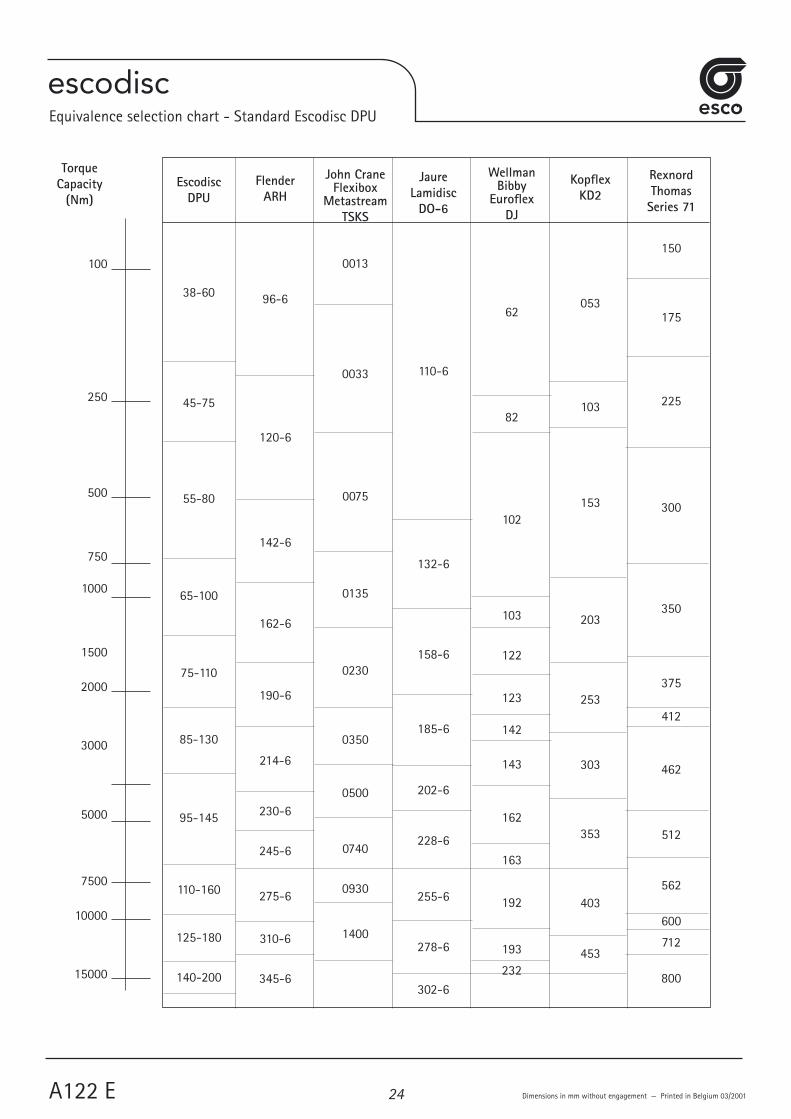
Equivalence selection chart - Standard Escodisc DPU
EscodiscDPU
38-60
45-75
55-80
65-100
75-110
85-130
95-145
110-160
125-180
140-200
FlenderARH
96-6
120-6
142-6
162-6
190-6
214-6
230-6
245-6
275-6
310-6
345-6
John CraneFlexibox
MetastreamTSKS
0013
0033
0075
0135
0230
0350
0500
0740
0930
1400
JaureLamidisc
DO-6
110-6
132-6
158-6
185-6
202-6
228-6
255-6
278-6
302-6
WellmanBibby
EuroflexDJ
62
82
102
103
122
123
142
143
162
163
192
193
232
KopflexKD2
053
103
153
203
253
303
353
403
453
RexnordThomasSeries 71
150
175
225
300
350
375
412
462
512
562
600
712
800
24

escodisc
Cement Mill
Printed in Belgium 03/2001
Fan application
25

escodisc
Escodisc Shaft Connections
Cylindrical Bore and Keyway(Esco uses H7 as standard bore toleranceand keyway is according to DIN 6885/1)
Conical Bore
External Clamping Device Internal Clamping Device
Clamping Hubs Split Clamping Hubs
For more details on the above mentioned Shaft Connections - Please Consult us
SHAFT CONNECTIONS
A123 E Dimensions in mm without engagement — Printed in Belgium 03/200126

escodisc
Balancing of escodisc couplings1. Balancing Requirements The actual requirement for balancing of a coupling depends amongst other on:- Manfacturing quality of the coupling (Natural Inherent Balance Quality)- Application speed- The mass of the coupling (relative to the masses of the machine rotors)- Distance between shaft ends- Sensitivity of the system
Thanks to their high manufacturing quality, escodisc couplings have a high degree of natural inherent balance and generally don't require additional balancing for normal speed applications. Up to size 95, escodisc DLC/DMU/DPU couplings have a minimum balance quality of Q6.3 at 1500 rpm. For larger sizes, Q6.3 is guaranteed without any additional balancing until 1000 rpm. In the below graph you can find when additional balancing is required based on application speed and DBSE. Also you c an find the maximum limits for high speed/long DBSE applications based on the coupling size. Above these limits, please consult us. For applications requiring additional balancing, the use of DLC couplings is not recommended.
2. Esco Balancing Procedures Based on the application data or specific customer requirements, Esco Transmissions will perform a component balancing to Q6.3
or Q2.5 (as specified - Q1 is obtainable yet not advisable for standard couplings) for standard couplings and a component balancing followed by an assembly balancing procedure for high speed applications. Esco transmissions will also perform balancing before the keyway, if any, is shaped in the coupling. Other balancing options are of course available upon request but must be cleary specified when ordering.
Remark: for DMU couplings, only component balancing is possible.
BALANCING
Dimensions in mm without engagement — Printed in Belgium 03/2001 A124 E27

escodiscREFERENCES
Escodisc References
Since 1986 escodisc standard, as well as special couplings have been in use in the chemical, petrochemical, pulp, paper, printing, textile, steel, cement and general machine building industry to full customer satisfaction.The field of application is various going from pumps, compressors, fans, turbines to water treatment installations, machining centers to even test benches for Formula 1 racing car...Thanks to this, esco has built up a level of expertise and knowledge from which our customers can benefit.
ABB Lumus GlobalBelgian Refining Corporation
BP Amoco ChemicalsCockerill Sambre
Corus SteelDow ChemicalsFina Refinery
Flowserve CorporationHowden
KSB PumpsPasaban
Pompes d'EnsivalShell International
Siam CementSolvay
Stora CellTHY Marcinelle
Valmet
Printed in Belgium 03/200128

escodisc
TABLE OF CONTENTS1. Introduction2. Preparation3. Warnings4. Assembly5. Inspection and maintenance
FLEXIBLE DISCS COUPLINGS
Printed in Belgium 12/2003 IM/A100-2
SERIE DL
INSTALLATION & MAINTENANCE
29

ESCODISC SERIE DL1. INTRODUCTION - Coupling must be selected properly according to selection chart A 103, A 104 and A 105 and corresponding charts (A110, A111 and A112). These documents are available in coupling catalogue ESCODISC or on our web site « www.escocoupling.com ». Maximum misalignment figures at as-sembly are given is this document (see point 4: assembly). Max misalignment figures in operation (combination of radial, angular and axial) are given in ESCODISC catalogue. Max misalignment values may not be applied simultaneously as mentioned in selection chart A 104. In case of any change or adaptation not performed by ESCO on the coupling, it is customer responsibility to size and manufacture it properly to guarantee safe torque transmission and absence of unbalance that could affect the life of the coupling and the connected machines. It is customer responsibility to make sure that shaft and key material, size and tolerance suit the application. Maximum bore capacity is given in the catalogue. If key assembly is not calculated and machined by ESCO, it is customer responsibility to make sure that hub length, bore size and machining tolerances will transmit the torque. If interference fit is not calculated and machined by ESCO, it is customer responsibility to make sure that interference and machining tolerances will transmit the torque and not exceed hub materiel permissible stress. The hubs must be axially secured on the shaft by means of a setscrew, an end plate or a sufficient interference. In case of spacer not supplied by ESCO, it is customer responsibility to size and manufacture it properly to guarantee safe torque transmission and absence of unbalance that could affect the life of the Discs. It is customer responsibility to prot�
2. PREPARATIONEnsure the conformity of the supplied equipment:--- Verify coupling size and conformity (see catalogue or web site). --- Identify any damaged and/or missing parts.--- Verify conformity of the coupling/machine interfaces.Coupling original protection allows for storage indoors dry 18 months, indoors humid 12 months, outdoors covered: 9 months and outdoors open 3 months. For longer periods, it is customer responsibility to protect the parts properly. Instructions are a part of the supply of the coupling. Be sure valid and complete assembly, operation and maintenance instructions are available. Make sure they are well understood. In case of doubt, refer to ESCO. Assembly, disassembly and maintenance must be performed by qualified, trained and competent fitters. Before starting with assembly, disassembly and maintenance, verify the availability of the tooling necessary --- To manipulate the parts --- To assemble the interfaces --- To align the coupling --- To tighten the screws and nuts.
3. WARNINGSBefore removing the coupling guard and proceeding with any assembly, operation or maintenance operation of the coupling, make sure the complete system is completely shut down and definitively disengaged from any possible source of rotation, such as, for example:--- Electrical power supply. --- Any loss of braking effect.Make sure everyone attending the equipment area will be properly informed (for example by means of warnings properly located) about the main-tenance or assembly situation.In case of use in explosive atmospheres , specific protective measures must be considered. They are described in an extra attach-ment (IM/A100-Ex) to the actual instructions with the couplings marked .
4. ASSEMBLY4.0. WARNING4.0.1 The hubs (1) and the spacer (2) are supplied unassembled. The discs (3) are supplied packed with the screws and nuts (4) under plastic
film to ensure a perfect protection. They will only be unpacked during final mounting on the machine.4.0.2 If coupling is supplied rough bored, bore and keyway must be machined in hubs (1). When machining the bore, surface marked (M) must
be taken as the turning reference.4.1. ASSEMBLY4.1.1 Ensure that parts are clean and mount the hubs (1) in the correct position on the shafts of the machines (the flange at the shaft end for the
DLC Series, the flange at the machine side for the DLCC Series). Hub faces must be flush with shaft end. In case of doubt, please consult us. Introduce setscrew on key with Loctite and tighten properly. In case of interference fit, refer to ESCO for proper instructions
4.1.2 Position the machines to be connected (for DLCC Series, the spacer (2) and the discs (3) must be placed on the hubs (1) during the installa-tion, see also point 4.1.4 and check distance G between the hubs (for the DLCC Series, check also distance A). See tabulation or approved drawing for distance G following type of coupling. In case of doubt, please consult us.
4.1.3 Align the shafts using an indicator. The alignment precision (X, Y - Z) is given in the tabulation.4.1.4 Ensure that the flanges of the hubs (1) and the spacer (2) are perfectly degreased. Unpack the discs and the screws. Mount the disc (3)
on one hub (1) with screws and nuts (4) in the direction shown on the fig. Tighten to torque T while holding the screws still and turning the nuts. See tabulation for tightening torque (T Nm) and socket size (s mm).
4.1.5 Install the spacer (2) between the hubs and connect it to the already assembled disc (3) with screws and nuts (4), in the direction shown on the fig. (in case of long spacer, it is essential to support the spacer in position from the beginning to the end of the assembly). Tighten to torque T mentioned while holding the screws still and turning the nuts. See tabulation for tightening torque (T Nm) and socket size (s mm).
4.1.6 En�4.1.7 Check once again the alignment by measuring the max. value H1 and the min. value H2 of the distance between the hub flange and the
spacer flange (see figure). See tabulation for the permissible values.
5. OPERATION, INSPECTION AND MAINTENANCE5.1. OPERATION AND MAINTENANCENo maintenance is necessary. It is however recommended to verify the alignment (see point 4.1.7) and the tightening torque of the screws and nuts (5) (see tabulation) after the first running hours. Every 6.000 hours or 12 month, inspect the discs for any fatigue crack and verify alignment.5.2. DISASSEMBLY AND INSPECTIONEvery 12.000 hours or every 24 month.5.2.1 Remove the screws and nuts (4) each side.5.2.2 Remove the spacer (2) and inspect the discs (3). In case of damage, the disc-pack (3) must be replaced.
IM/A100-2 - Printed in Belgium 12/200330

escodisc
GStandard
mm
100
100
100
100
100
100
140
G(optional)
mm
(140)
(140)
(140)
(140)
(140, 180)
(140, 180)
(180, 250)
G
mm
56
46
26
22
4
4
4
28
38
45
55
65
75
85
DLCCDLC
A
mm
116
116
116
122
122
132
174
X
mm
0,10
0,10
0,10
0,10
0,10
0,10
0,15
Y - Z max. mm
0,10
0,10
0,10
0,20
0,20
0,20
0,25
H1 - H2
max.mm
0,10
0,11
0,12
0,16
0,19
0,22
0,25
Distances - Afstanden - AbstandAvstand - Distancias - Distanze - Etäisyydet -
H1 + H2
mm
6,5 ± 0,2
6,7 ± 0,2
6,5 ± 0,2
7,0 ± 0,2
9,0 ± 0,2
10,0 ± 0,3
13,0 ± 0,4
TypeSizeTypTipo
StorlekTamaño
Koko
Alignement - Uitlijning - Alignment - VerlagerungUppriktning - Alineación - Allineamento - Poikkeamat
DLC DLCC
T
Nm
12,5
12,5
12,5
30
60
100
160
Sizes
mm
10
10
10
13
17
19
22
Drivermm
1/4
1/4
1/4
3/8
1/2
1/2
1/2
2
Socket
IM/A100-2 - Printed in Belgium 03/2006
SERIE DL
31

32

escodisc
TABLE OF CONTENTS1. Introduction2. Preparation3. Warnings4. Assembly5. Inspection and maintenance
FLEXIBLE DISCS COUPLINGS
Printed in Belgium 12/2003 IM/A100-3
SERIE DMU
INSTALLATION & MAINTENANCE
33

IM/A100-3 - Printed in Belgium 12/2003
ESCODISC SERIE DMU
1. INTRODUCTION Coupling must be selected properly according to selection chart A 103, A 104 and A 105 and corresponding chart (A115). These documents are available in cou-pling catalogue ESCODISC or on our web site « www.escocoupling.com ». Maximum misalignment figures at assembly are given is this document (see point 4: assembly). Max misalignment figures in operation (combination of radial, angular and axial) are given in ESCODISC catalogue. Max misalignment values may not be applied simultaneously as mentioned in selection chart A 104. In case of any change or adaptation not performed by ESCO on the coupling, it is customer responsibility to size and manufacture it properly to guarantee safe torque transmission and absence of unbalance that could affect the life of the coupling and the connected machines. It is customer responsibility to make sure that shaft and key material, size and tolerance suit the application. Maximum bore capacity is given in the catalogue. If key assembly is not calculated and machined by ESCO, it is customer responsibility to make sure that hub length, bore size and machining toler-ances will transmit the torque. If interference fit is not calculated and machined by ESCO, it is customer responsibility to make sure that interference and machining tolerances will transmit the torque and not exceed hub materiel permissible stress. The hubs must be axially secured on the shaft by means of a setscrew, an end plate or a sufficient interference. In case of spacer not supplied by ESCO, it is customer responsibility to size and manufacture it properly to guarantee safe torque transmission and absence of unbalance that could affect the life of the Discs. It is customer responsibility to protect the coupling by p.ex. a coupling guard and to comply with the local safety rules regarding the protection of rotating parts.2. PREPARATIONEnsure the conformity of the supplied equipment:--- Verify coupling size and conformity (see catalogue or web site). --- Identify any damaged and/or missing parts.--- Verify conformity of the coupling/machine interfaces.Coupling original protection allows for storage indoors dry 18 months, indoors humid 12 months, outdoors covered: 9 months and outdoors open 3 months. For longer periods, it is customer responsibility to protect the parts properly. Instructions are a part of the supply of the coupling. Be sure valid and complete assembly, operation and maintenance instructions are available. Make sure they are well understood. In case of doubt, refer to ESCO. Assembly, disassembly and main-tenance must be performed by qualified, trained and competent fitters. Before starting with assembly, disassembly and maintenance, verify the availability of the tooling necessary --- To manipulate the parts --- To assemble the interfaces --- To align the coupling --- To tighten the screws and nuts.3. WARNINGSBefore removing the coupling guard and proceeding with any assembly, operation or maintenance operation of the coupling, make sure the complete system is completely shut down and definitively disengaged from any possible source of rotation, such as, for example:--- Electrical power supply. --- Any loss of braking effect.Make sure everyone attending the equipment area will be properly informed (for example by means of warnings properly located) about the maintenance or as-sembly situation.In case of use in explosive atmospheres , specific protective measures must be considered. They are described in an extra attachment (IM/A100-Ex) to the actual instructions with the couplings marked .4. ASSEMBLY4.0. WARNING4.0.1 The hubs (1) and the spacer (4) are supplied unassembled. The disc-packs (3) are supplied packed with the screws (2) and nuts (5) under plastic film to
ensure a perfect protection. They will only be unpacked during final mounting on the machine.4.0.2 If coupling is supplied rough bored, bore and keyway must be machined in hubs (1). When machining the bore, surface marked (M) must be taken as the
turning reference.4.1. ASSEMBLY4.1.1 Ensure that parts are clean and mount the hubs (1) in the correct position on the shafts of the machines (the flange at the shaft end). Hub faces must be
flush with shaft end. In case of doubt, please consult us. Introduce setscrew on key with Loctite and tighten properly. In case of interference fit, refer to ESCO for proper instructions
4.1.2 Position the machines to be connected and check distance G between the hubs (fig. 1). See tabulation or approved drawing for distance G following type of coupling. In case of doubt, please consult us.
4.1.3 Align the shafts using an indicator. The alignment precision (X, Y - Z) is given in the tabulation.
4.1.4 Ensure that the flanges of the hubs (1) and the spacer (4) are perfectly degreased. Unpack the discs and the screws. Mount the disc-pack (3) on one hub (1) with screws (2) and nuts (5) in the direction shown on the fig 2. Tighten to torque T mentioned while holding the screws still and turning the nuts. See tabulation for tightening torque (T Nm) and socket size (s mm).
4.1.5 Install the spacer (4) between the hubs and connect it to the already assembled disc-pack (3) with screws (2) and nuts (5), in the direction shown on the fig. 3 (in case of long spacer, it is essential to support the spacer in position from the beginning to the end of the assembly). Tighten to torque T mentioned in the tabulation while holding the screws still and turning the nuts.
4.1.6 Engage the �g. 4).4.1.7 Check once again the alignment by measuring the max. value H1 and the min. value H2 of the distance between the hub flange and the spacer flange (see
figure 5). See tabulation for the permissible values.5. OPERATION, INSPECTION AND MAINTENANCE5.1. OPERATION AND MAINTENANCENo maintenance is necessary. It is however recommended to verify the alignment (see point 4.1.7) and the tightening torque of the screws (2) and nuts (5) (see tabulation) after the fir�5.2. DISASSEMBLY AND INSPECTIONEvery 12.000 hours or every 24 month.5.2.1 Remove the screws (2) and nuts (5) each side.5.2.2 Remove the spacer (4) and inspect the discs (3). In case of damage, the disc-pack (3) must be replaced.
34

escodisc
IM/A100-3 - Printed in Belgium 12/2003
FIG. 5
FIG. 1
FIG. 2
FIG. 3
FIG. 4
GStandard
mm
100
100
100
100
140
140
140
180
180
250
250
38
45
55
65
75
85
95
110
125
140
160
DBSE
X
mm
0,10
0,10
0,10
0,10
0,12
0,12
0,12
0,15
0,20
0,20
0,20
Y - Z max. mm
0,10
0,10
0,20
0,20
0,20
0,25
0,25
0,30
0,30
0,40
0,40
H1 - H2
max.mm
0,11
0,12
0,15
0,18
0,20
0,23
0,27
0,30
0,33
0,37
0,42
Distances - Afstanden - Abstand - Avstand Distancias - Distanze - Etäisyydet
TypeSizeTypTipo
StorlekTamaño
Koko
Alignement - Uitlijning - Alignment - VerlagerungUppriktning - Alineación - Allineamento - Poikkeamat
H1 + H2
mm
6,7 ± 0,15
6,5 ± 0,20
7,0 ± 0,2
9,0 ± 0,20
10,0 ± 0,30
13,0 ± 0,40
14,0 ± 0,40
15,5 ± 0,40
19,0 ± 0,50
20,0 ± 0,60
20,0 ± 0,70
2T
Nm
14
14
34
67
114
180
277
380
540
725
920
Sizes
mm
10
10
13
17
19
22
24
27
30
32
36
Drivermm
1/4
1/4
3/8
1/2
1/2
1/2
1/2
3/4
3/4
3/4
3/4
Socket
SERIE DMU
35

36

escodisc
TABLE OF CONTENTS1. Introduction2. Preparation3. Warnings4. Assembly5. Inspection and maintenance
FLEXIBLE DISCS COUPLINGS
Printed in Belgium 05/2006 IM/A100-4
SERIE DPU
INSTALLATION & MAINTENANCE
37

ESCODISC SERIE DPU1. INTRODUCTIONCoupling must be selected properly according to selection chart A 103, A 104 and A 105 and corresponding chart (A121). These documents are available in cou-pling catalogue ESCODISC or on our web site « www.escocoupling.com ». Maximum misalignment figures at assembly are given is this document (see point 4: assembly). Max misalignment figures in operation (combination of radial, angular and axial) are given in ESCODISC catalogue. Max misalignment values may not be applied simultaneously as mentioned in selection chart A 104. In case of any change or adaptation not performed by ESCO on the coupling, it is customer responsibility to size and manufacture it properly to guarantee safe torque transmission and absence of unbalance that could affect the life of the coupling and the connected machines. It is customer responsibility to make sure that shaft and key material, size and tolerance suit the application. Maximum bore capacity is given in the catalogue. If key assembly is not calculated and machined by ESCO, it is customer responsibility to make sure that hub length, bore size and machining toler-ances will transmit the torque. If interference fit is not calculated and machined by ESCO, it is customer responsibility to make sure that interference and machining tolerances will transmit the torque and not exceed hub materiel permissible stress. The hubs must be axially secured on the shaft by means of a setscrew, an end plate or a sufficient interference. In case of spacer not supplied by ESCO, it is customer responsibility to size and manufacture it properly to guarantee safe torque transmission and absence of unbalance that could affect the life of the Discs. It is customer responsibility to protect the coupling by p.ex. a coupling guard and to comply with the local safety rules regarding the protection of rotating parts.
2. PREPARATIONEnsure the conformity of the supplied equipment:--- Verify coupling size and conformity (see catalogue or web site). --- Identify any damaged and/or missing parts.--- Verify conformity of the coupling/machine interfaces.Coupling original protection allows for storage indoors dry 18 months, indoors humid 12 months, outdoors covered: 9 months and outdoors open 3 months. For longer periods, it is customer responsibility to protect the parts properly. Instructions are a part of the supply of the coupling. Be sure valid and complete assembly, operation and maintenance instructions are available. Make sure they are well understood. In case of doubt, refer to ESCO. Assembly, disassembly and maintenance must be performed by qualified, trained and competent fitters. Before starting with assembly, disassembly and maintenance, verify the availability of the tooling necessary --- To manipulate the parts --- To assemble the interfaces--- To align the coupling --- To tighten the screws and nuts.
3. WARNINGSBefore removing the coupling guard and proceeding with any assembly, operation or maintenance operation of the coupling, make sure the complete system is completely shut down and definitively disengaged from any possible source of rotation, such as, for example:--- Electrical power supply. --- Any loss of braking effect.Make sure everyone attending the equipment area will be properly informed (for example by means of warnings properly located) about the maintenance or as-sembly situation.In case of use in explosive atmospheres , specific protective measures must be considered. They are described in an extra attachment (IM/A100-Ex) to the actual instructions with the couplings marked .
4.0. WARNING4.0.1 The pack sub-assembly (1) including flange DP (1.1) discs (1.2), sandwich flange (1.3) and bolts and nuts (1.4) has to be considered as one single component. Bolts
have been factory tightened for optimal torque transmission and infinite life. It may not be disassembled. Any external intervention to this sub-assembly (torquing bolts and nuts, separating components) will automatically cancel suppliers guarantee, customer being fully responsible of any operation risk and damage.
4.0.2 The pack sub-assembly (1) is supplied compressed and fixed by shipping screws (15). This arrangement protects the flexible discs during storage and shipment and makes assembly easier. These shipping screws (15) must be removed at assembly and before starting the machines (see point 4.1.5).
4.0.3 If coupling is supplied rough bored, bore and keyway must be machined in hubs (8) and (9). When machining the bore, surface marked (M) must be taken as the turning reference.
4.0.4 It is customer’s responsibility to protect the coupling and to conform his equipment do local safety legislation.
4.1. ASSEMBLY4.1.1 Install hubs (8) and (9) on their respective shafts in their proper position (see fig. 6). Hub faces must be flush with shaft end. In case of doubt, please consult
us. Introduce setscrew on key with Loctite and tighten properly. In case of interference fit, refer to ESCO for proper instructions.4.1.2 Position units to be connected and check distance G between the hubs. See tabulation or approved drawing for correct distance G, according to coupling
type. In case of doubt, please consult us.4.1.3 Align the two shafts using an indicator. Alignment precision (X and Y - Z) is given in alignment tabulation (fig. 6).4.1.4 Ensure that both spacer ends (2) and DP flange (1.1) are perfectly degreased. Mount (see fig. 2) hub sub-assemblies (1) on spacer (2) with screws (3) and
washers (4). Tighten screws (3) uniformly (tightening torque T3). See tabulation for correct tightening torque (Spacer T3 Nm) and key size (s mm).4.1.5 Ensure that both hub faces (8) and (9) and sandwich flange (1.3) are perfectly degreased. Introduce floating assembly between the two hubs (fig. 3). Remove
the shipping screws (15) with rings (17) and shipping inserts (16) at each end (fig. 4). The floating assembly must be maintained in position by the two hubs (8)�
4.1.6 Engage the 6 or 8 screws (5) and washers (6) or/and the 6 or 8 screws and nuts (7) (following case) in each hub (fig. 5). Tighten the screws (5) or (7) uniformly (tightening torque T5). See tabulation for correct tightening torque T5 Nm and Allen key (s mm).
4.1.6a ASSEMBLY DPULE (limited end float) During assembly of each 6 or 8 screws (5) and washers (6) or/and each 6 or 8 screws and nuts (7) (following case) and on each side, slip one « axial limiter
short » between the DP flange (1.1) and the sandwich flange (1.3) of the pack sub-assembly (1) and one « axial limiter long » in each hole of the DP flange (1.1) (fig. 7). Tighten the screws (5) or (7) uniformly (tightening torque T5). See tabulation for correct tightening torque T5 Nm and Allen key (s mm).
4.1.7 Check once again alignment and axial distance by measuring max. value H1 and min. value H2 of the distance between flange DP (1.1) and sandwich flange 1.3) (see figure). See alignment tabulation for permissible values.
5. OPERATION, INSPECTION AND MAINTENANCE5.1. OPERATION AND MAINTENANCENo maintenance is necessary; however, it is recommended to verify alignment (see point 4.1.7) and tightening torque of the screws (5) (see point 4.1.6) after the fir�5.2. DISASSEMBLY AND INSPECTIONEvery 12.000 hours or every 24 month.5.2.1 Remove the 6 screws (5) or (7) (according to the case) each side. Introduce the shipping screws (15) and shipping inserts (16) and tighten the screws (15)
to compress pack sub-assembly (1). Note that the minimum distance H0 in stationary condition between flange DP (1.1) and sandwich flange (1.3) should never be less than H0 given in tabulation.
5.2.2 Remove floating assembly (2) and inspects discs (1.2) without dismounting hub sub-assembly (1) (see point 4.0.1). In case of damage, complete sub-as-sembly (1) must be replaced.
IM/A100-4 - Printed in Belgium 05/200638

IM/A100-3 - Printed in Belgium 05/2008
SERIE DMU
FIG. 5
FIG. 1
FIG. 2
FIG. 3
FIG. 4
GStandard
mm
100
100
100
100
140
140
140
180
180
250
250
250
280
300
340
380
400
38
45
55
65
75
85
95
110
125
140
160
190
220
250
280
320
360
DBSE
X
mm
0,12
0,08
0,08
0,08
0,11
0,11
0,11
0,14
0,14
0,20
0,20
0,13
0,15
0,11
0,13
0,12
0,13
Y - Z max. mm
0,24
0,16
0,16
0,16
0,22
0,22
0,22
0,28
0,28
0,40
0,40
0,26
0,29
0,22
0,26
0,23
0,26
H1 - H2
max.mm
0,24
0,17
0,19
0,21
0,26
0,28
0,30
0,36
0,38
0,46
0,50
0,35
0,40
0,34
0,37
0,33
0,37
Distances - Afstanden - Abstand - Avstand Distancias - Distanze - Etäisyydet
TypeSizeTypTipo
StorlekTamaño
Koko
Alignement - Uitlijning - Alignment - VerlagerungUppriktning - Alineación - Allineamento - Poikkeamat
H1 + H2
mm
6,7 ± 0,25
6,5 ± 0,20
7,0 ± 0,25
9,0 ± 0,25
10,0 ± 0,30
13,0 ± 0,40
14,0 ± 0,40
15,5 ± 0,45
19,0 ± 0,50
20,0 ± 0,65
20,0 ± 0,70
19,25 ± 0,50
24,6 ± 0,65
38,0 ± 0,75
41,0 ± 0,80
44,9 ± 0,90
34,0 ± 0,60
2T
Nm
14
14
34
67
114
180
277
380
540
725
920
540
920
1855
2490
3180
3180
Sizemm
10
10
13
17
19
22
24
27
30
32
36
30
36
46
50
55
55
Drivermm
1/4
1/4
3/8
1/2
1/2
1/2
1/2
3/4
3/4
3/4
3/4
3/4
3/4
3/4
1
1
1
Socket
35

40

escodisc
TABLE OF CONTENTS1. Introduction2. Preparation3. Warnings4. Assembly5. Inspection and maintenance
FLEXIBLE DISCS COUPLINGS
Printed in Belgium 12/2003 IM/A100-5
SERIE DMUCC
INSTALLATION & MAINTENANCE
41

ESCODISC SERIE DMUCC
1. INTRODUCTION Coupling must be selected properly according to selection chart A 103, A 104 and A 105 and corresponding chart (A117). These documents are available in cou-pling catalogue ESCODISC or on our web site « www.escocoupling.com ». Maximum misalignment figures at assembly are given is this document (see point 4: assembly). Max misalignment figures in operation (combination of radial, angular and axial) are given in ESCODISC catalogue. Max misalignment values may not be applied simultaneously as mentioned in selection chart A 104. In case of any change or adaptation not performed by ESCO on the coupling, it is customer responsibility to size and manufacture it properly to guarantee safe torque transmission and absence of unbalance that could affect the life of the coupling and the connected machines. It is customer responsibility to make sure that shaft and key material, size and tolerance suit the application. Maximum bore capacity is given in the catalogue. If key assembly is not calculated and machined by ESCO, it is customer responsibility to make sure that hub length, bore size and machining toler-ances will transmit the torque. If interference fit is not calculated and machined by ESCO, it is customer responsibility to make sure that interference and machining tolerances will transmit the torque and not exceed hub materiel permissible stress. The hubs must be axially secured on the shaft by means of a setscrew, an end plate or a sufficient interference. In case of spacer not supplied by ESCO, it is customer responsibility to size and manufacture it properly to guarantee safe torque transmission and absence of unbalance that could affect the life of the Discs. It is customer responsibility to protect the coupling by p.ex. a coupling guard and to comply with the local safety rules regarding the protection of rotating parts.2. PREPARATIONEnsure the conformity of the supplied equipment:--- Verify coupling size and conformity (see catalogue or web site). --- Identify any damaged and/or missing parts.--- Verify conformity of the coupling/machine interfaces.Coupling original protection allows for storage indoors dry 18 months, indoors humid 12 months, outdoors covered: 9 months and outdoors open 3 months. For longer periods, it is customer responsibility to protect the parts properly. Instructions are a part of the supply of the coupling. Be sure valid and complete assembly, operation and maintenance instructions are available. Make sure they are well understood. In case of doubt, refer to ESCO. Assembly, disassembly and main-tenance must be performed by qualified, trained and competent fitters. Before starting with assembly, disassembly and maintenance, verify the availability of the tooling necessary --- To manipulate the parts --- To assemble the interfaces--- To align the coupling --- To tighten the screws and nuts.3. WARNINGSBefore removing the coupling guard and proceeding with any assembly, operation or maintenance operation of the coupling, make sure the complete system is completely shut down and definitively disengaged from any possible source of rotation, such as, for example:--- Electrical power supply. --- Any loss of braking effect.Make sure everyone attending the equipment area will be properly informed (for example by means of warnings properly located) about the maintenance or as-sembly situation.In case of use in explosive atmospheres , specific protective measures must be considered. They are described in an extra attachment (IM/A100-Ex) to the actual instructions with the couplings marked .
4. ASSEMBLY4.0. WARNING4.0.1 The hub sub-assembly including the hub (1), the disc-pack (2), the rings (3), the screws (C), the nuts (B) and the sandwich flange (5) are factory pre-as-
sembled and may not be disassembled unless in case of disc-pack change (see figure 1 and point 5.2.2). 4.0.2 The hub sub-assembly indicated in 4.0.1. is supplied compressed and rigidified with shipping screws (10), rings (9) and inserts (8). These shipping screws
must be removed at assembly and before starting the machines (see point 4.1.8.). 4.0.3 If hubs are supplied rough bored, bore and keyway must be machined in the hubs (1):· Without dismounting the sub-assembly (see point 0.1.)· Without dismounting the shipping screws (10)· Taking the surface marked (M) as the turning reference.4.1. ASSEMBLY4.1.1 Dismount spacer in two parts (4) by removing screws (7) and washers (6) on both sides. 4.1.2 Clean all the parts thoroughly.4.1.3 Mount the hub sub-assemblies on their respective shafts. The hub faces must be flush with the shaft ends. In case of doubt, please consult us. 4.1.4 Position the units to be connected and check the distance G between the hubs(for spacer (4) in one piece, check also distance A) . See tabulation or (in
case of a sp�4.1.5 Align the two shafts (see figure 2 and 3). Alignment precision (X and Y - Z) is given in tabulation.4.1.6 Ensure that spacer (4) ends and sandwich flanges (5) faces are perfectly degreased. Introduce spacer in two parts (4) between the two sub-assemblies.
Engage 2 or 1 screws (7) with their rings (6) in both ends of both spacer parts (4).4.1.7 Remove the shipping screws (10) with their rings (9) and their inserts (8) at each end (see figure 4) and engage the 3 remaining screws (7) with their rings
(6) in each spacer end (see figure 4). Tighten screws uniformly using the tightening torque (T1 in Nm) and key size (s mm) indicated in tabulation.4.1.8 Check alignment and axial distance by measuring the max. value H1 and the min. value H2 of the distance between the hub (1) flange and the sandwich
flange (5) (see figure 5). See tabulation for permissible values.5. OPERATION, INSPECTION AND MAINTENANCE5.1. OPERATION AND MAINTENANCENo maintenance is necessary. However it is recommended to verify alignment and tightening torque T1 of the screws (7) after the first running hours. Every 6.000
hours or 12 month, inspect external discs of disc pack for any fatigue crack and verify alignment.5.2. DISASSEMBLY AND INSPECTIONEvery 12.000 hours or every 24 month.5.2.1 Remove the 6 screws (7) with their rings (6) on both sides. Introduce the shipping screws (10) with their rings (9) and their inserts (8) at each end and tighten
the screws (10) to compress the two disc-packs. Note that the minimum distance H0 in stationary condition between the hub (1) flange and the sandwich flange (5) should never be less than the H0 value given in the tabulation.
5.2.2 Remove the spacer (4) in two parts and inspect the discs (2). In case of breakage, the disc-packs (2) must be replaced respecting assembly indicated in the figure 1. The tightening torque T2 (in Nm) and socket size (s mm).of the screws (C) and the nuts (B) is given tabulation.
IM/A100-5 - Printed in Belgium 12/200342

escodisc
IM/A100-5 - Printed in Belgium 12/2003
SERIE DMUCC
GStandard
mm
3
3
4
4
4
4
6
6
6
8
45
55
65
75
85
95
110
125
140
160
DBSE
X
mm
0,10
0,10
0,10
0,10
0,20
0,20
0,20
0,25
0,30
0,35
Y - Z max. mm
0,10
0,20
0,20
0,20
0,25
0,25
0,30
0,30
0,40
0,40
H1 - H2
max.mm
0,12
0,16
0,19
0,22
0,25
0,29
0,32
0,36
0,40
0,45
Distances - Afstanden - Abstand - Avstand Distancias - Distanze
- Etäisyydet
TypeSizeTypTipo
StorlekTamaño
Koko
Alignement - Uitlijning - Alignment - VerlagerungUppriktning - Alineación - Allineamento - Poikkeamat
H1 + H2
mm
6,5 ± 0,20
7,0 ± 0,20
9,0 ± 0,20
10,0 ± 0,30
13,0 ± 0,40
14,0 ± 0,40
15,5 ± 0,50
19,0 ± 0,50
20,0 ± 0,50
20,0 ± 0,60
2 T1 Nm
8,1
13,2
32
55
63
100
108
180
230
280
smm
4
5
6
8
8
10
10
12
14
14
T2Nm
14
34
67
114
180
277
380
540
725
920
H0
mm
5,5
5,7
7,6
8?3
11
12
13,4
17,0
17,5
17,5
Sizemm
10
13
17
19
22
24
27
30
32
36
Drivermm
1/4
3/8
1/2
1/2
1/2
1/2
3/4
3/4
3/4
3/4
AStandard
mm
93
103
122
132
174
194
226
256
286
328
Spacer Disc Pack
43

Printed in Belgium 08/2008 IMA100-Ex Rev.2
Attachment : Specifi c Protective Measures Taken forESCODISC Couplings in case of use in explosive atmospheres.
0 IntroductionGeneral assembly and maintenance instructions (called IM/... in this attachment), are established for standard ESCODISC couplings according to the following list:IM/A100-2 for ESCODISC DLC couplings - IM/A100-3 for ESCODISC DMU couplingsIM/A100-4 for ESCODISC DPU couplings - IM/A100-5 for ESCODISC DMUCC couplingsIn case of use in potentially explosive atmospheres , further to the general assembly and maintenance instructions(IM/...), the specifi c measures described in this attachment must be taken.
1 Coupling SelectionThe coupling must be selected according to the general assembly and maintenance instructions IM/... .In explosive atmosphere , the following specifi c rules must apply:A Service Factor of 1.5 must be applied on the max torque values for nominal torque (Tn) and peak torque (Tp) given in the charts in catalogue (see Selection chart A104 and A105).
2 Use of the couplingThe coupling is dedicated for use in potentially explosive atmospheres according to European Directive 94/9/EC (Atex 100 A). Coupling is classifi ed in equipment group II, equipment category 2 and 3, intended for use in areas in which explosive atmospheres caused by gases, vapors, mists of air/dust mixtures are likely to occur.In function of the ambient temperature in the coupling proximity (85, 55, 45°C), the temperature classes have been defi ned (T4, T5, T6).This is based on a temperature increase of the machine shafts (in regard of the ambient temperature) that will not exceed 50°C in operation.
The coupling is marked as follows: CE II 2 G T4/T5/T6 D 120°C -20°C ≤ Ta ≤ 85°C / 55°C / 45°CThis marking covers the T3 temperature category. - This marking covers all gas categories: G IIA, G IIB and G IIC.
3. WarningsThe warnings mentioned in the general assembly and maintenance instructions IM/... must apply in any case.In explosive atmosphere , the following specifi c warnings must apply:• Complete machining of the coupling parts (bores, keyways, spacers, fl oating shafts etc…) must be performed by ESCO Couplings N.V. No modifi cation shall be
made on the supplied and marked product without the agreement of ESCO Couplings N.V.• In case of supply by ESCO Couplings of couplings with a rough bore or a solid bore, the sole allowed operation that may be performed by the customer is the
boring and keywaying of the coupling hubs. When machining the bore and the keyway, the following instructions must be followed: o This job must be performed by an authorised and adequately trained and informed operator. o The bore and keyway tolerances must be selected to insure the proper fi t between shaft and bore. In case of loose fi t, a set screw must be foreseen to locate
the hub axially. o The max bore may not exceed the value stated in the catalogue. The tabulated values in the catalogue are based on key dimensions according to ISO R 773. o The reference used to centre the piece when boring, is the one referenced D in the fi gures of the catalogue.• Before proceeding with any assembly, operation or maintenance operation on the coupling, make sure that the necessary measures have been taken to ensure
safety, such as but not limited to: o Proper ventilation of the area o Proper lightening and electrical tools.• If hub must be heated for assembly on the shaft, make sure heating source and surface temperature will not affect the safety of the working area.• It is recommended to have a strong coupling guard, preferably in stainless steel with openings (if any) smaller than the smallest centrifugable part (nut is 10 mm dia). The coupling guard is intended to protect the environment from the centrifugation of any rotating part and the rotating coupling from any falling part. To limit ventilation effects, distance between cover and coupling outside surface should be at least 10 mm.
4. AssemblyThe general assembly and maintenance instructions IM/... must apply in any case.In explosive atmosphere , the following specifi c instructions must apply:Alignment of the machine in cold condition must take into account the possible heat expansion to make sure that in continuous running conditions, max misalignment calculated on the base of selection chart A104 will not exceed 80% of the max allowed value: Da/∆ka + α/∆kw + dr/∆kr ≤ 0.80
5. OperationThe general assembly and maintenance instructions IM/... must apply in any case.In explosive atmosphere , the following specifi c instructions must apply:• Before Start-up o Make sure coupling is perfectly clean and properly aligned. o Make sure, screws, nuts are properly tightened. o Coupling guard must be properly installed and fi xed. o Monitoring system, if any, must be tested to verify its effectiveness.• During start up o Check for any abnormal noise and/or vibration. If any, immediate stop is mandatory and appropriate action must be taken.• Checking intervals during operation o After the fi rst 3000 hours or 6 months: � Inspect external disc for any fatigue crack. � Verify alignment• Continuous checking o Immediately stop the machine if noise, vibrations or other abnormal phenomena are detected during operation. o Further more, if direct check is not possible for access or safety reasons, proper monitoring system has to be installed to follow up couplings behaviour
6. MaintenanceThe general assembly and maintenance instructions IM/... must apply in any case.
In explosive atmosphere , the following specifi c instructions must apply:• Every 8.000 hours or 18 month: o Dismount the coupling and inspect. o Proceed as indicated in point 4.
44


Esco Couplings N.V.Kouterveld - Culliganlaan, 3B - 1831 Diegem (Brussels)(tel) + 32 02 715 65 60(fax) + 32 02 720 83 62 - 02 721 28 27e-mail: [email protected] web site: www.escocoupling.com
Esco Transmissions S.AZ.I. 34, rue Ferme Saint-LadreSaint WitzF - 95471 Fosses Cedex(tel) + 33 (1) 34 31 95 95(fax) + 33 (1) 34 31 95 99e-mail: [email protected] site: www.esco-transmissions.fr
Eugen Schmidt und CoGetriebe und Antriebselemente GmbHBiberweg 10D - 53842 Troisdorf(tel) + 49 (02241) 48070(fax) + 49 (02241) 480710e-mail: [email protected] site: www.esco-antriebstechnik.de
Esco Aandrijvingen B.V.Ondernemingsweg, 19 - P.B. 349NL - 2404 HM Alphen A/D Rijn(tel) + 31 (0) 172 / 42 33 33(fax) + 31 (0) 172 / 42 33 42e-mail: [email protected] site: www.esco-aandrijvingen.nl
Other coupling types available
Escogear CST / CST...M Escogear FST
Escogear NST
Escodisc DLC / DMU / DPU
Escofl ex A-R-S-TEsconyl A-B-C Escorail FTRN /FTRNO
Last version available on our Web site www.escocoupling.com Printed in Belgium 07/2008
Escospeed DHSU - GHS
Esco Couplings & Transmissions Pvt. Ltd.Shed No. B-325, 1st Stage, 3rd Main Road Peenya Industrial Estate Bangalore 560 058 INDIA(tel) + 91 80 4167 4858(fax) + 91 80 4155 8494e-mail: [email protected]