esa modelling progress - sintef · esa modelling and cycle design ... • detailed 3d modeling of...
TRANSCRIPT
ESA modelling and cycle design
MATESA Dissemination day, Oslo 16.6.2016
University of Belgrade
WP 2 and WP 5

Motivation
• Develop rigorous 3D models (CFD) to understand the processes, examine the influence of conditions / parameters and have a basis for model reduction
• Develop simplified 1D models for cycle simulations, with model parameters estimated based on 3D simulations
• Design ESA cycle that will satisfy demands for high Purity (P>95%) and Recovery (R>90%)
• Analyze electric energy consumption and relations to P and R• Analyze options to reduce the electric power consumption by
means of heat recovery and use of existing thermal power• Relate the results to experimental data
3D modelling
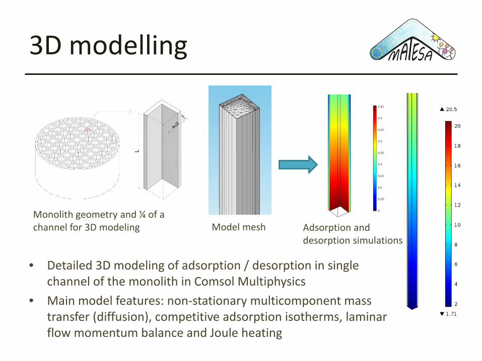
• Detailed 3D modeling of adsorption / desorption in single channel of the monolith in Comsol Multiphysics
• Main model features: non-stationary multicomponent mass transfer (diffusion), competitive adsorption isotherms, laminar flow momentum balance and Joule heating
Monolith geometry and ¼ of a channel for 3D modeling Adsorption and
desorption simulationsModel mesh
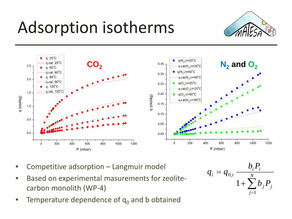
Adsorption isotherms
• Competitive adsorption – Langmuir model• Based on experimental masurements for zeolite-
carbon monolith (WP-4)• Temperature dependence of q0 and b obtained
∑=
+= N
jjj
iiii
Pb
Pbqq
1
,0
1
CO2 N2 and O2

3D simulations - resultsCO2concentration in gas (channel) at certain position and time
CO2concentration in solid (adsorbent) at certain position and time
Gas temperature at certain position and time
Solid temperature at certain position and time

3D results – effect of parameters
Influence of gas velocity and geometry
Influence of diffusion coefficients in solid
Influence of competing adsorbates (including water)
Influence of electrical potential
CO2 breakthrough curves
Desorption
1D modelling
• Simplified model developed for the purpose of cycle design, simulations and analysis
• The model consists of non-stationary 1D material, energy and momentum balances for the gas phase (channel) and monolith wall mass and energy balance
• Implemented in gPROMS• The 3D model simulation results used as “numerical
experiments” for estimation of the 1D model parameters – model reduction study

3D to 1D model reduction
3D simulations under various conditions to estimate the key 1D model parameters – new correlations derived
( ) ( )2
ch
2ch
2chi
bchi
c
iax2
c
i
aa2a
tqC
L1CD
L1
tC −+
∂∂−
∂∂
−
∂∂
∂∂=
∂∂ ∆ρ
ςυ
ςς( )qqk
tq *
i −=∂∂
( ) ( )sgg,pgchg
c
gg,pgaxh2
c
gg,pg TTh
cTL1T
cDL1
tT
c −⋅−∂
∂−
∂∂
∂∂=
∂∂
ςρυ
ςρ
ςρ
( )( )
( )( )( ) cchch
an
i
iib
chch
chsg
ss
c
sspb Laa
IUtqH
aaaTThT
LtTc
⋅−∆+⋅
+∂∂
∆−+−∆+
−⋅+
∂∂
∂∂
=∂∂ ∑
=22
122
2
2, 221 ρ
ςλ
ςρ
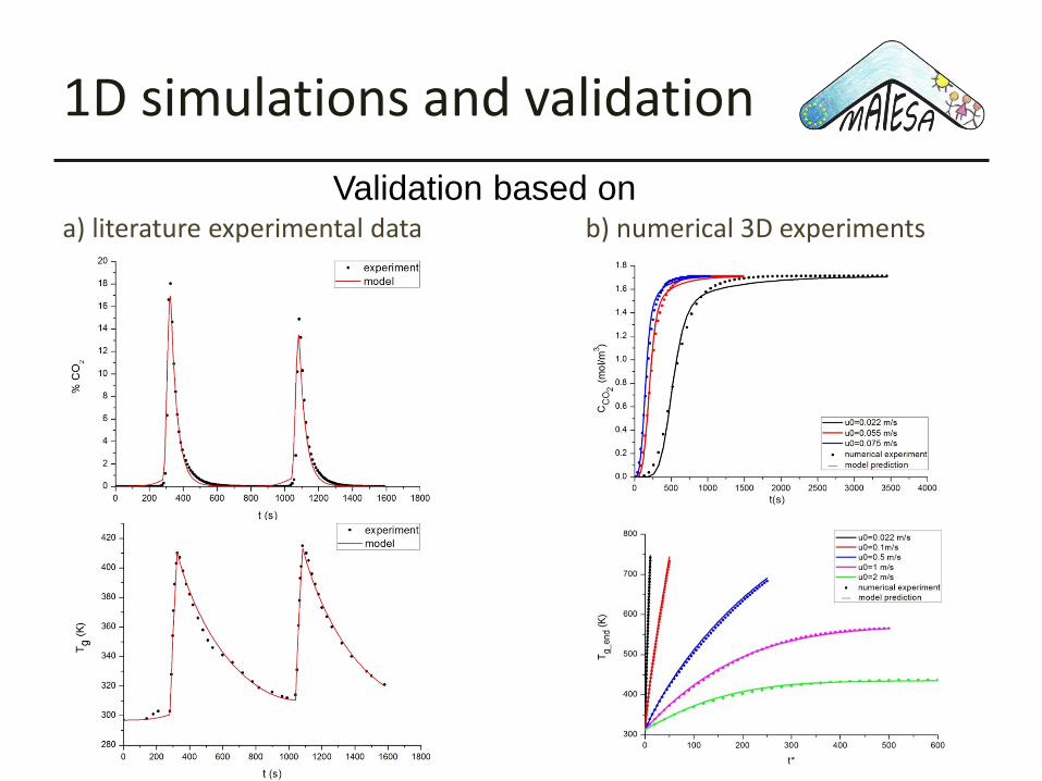
1D simulations and validation
a) literature experimental data b) numerical 3D experimentsValidation based on

ESA cycle build-up
Simplest cycle with adsorption (1), desorption with electrification (2) and cooling (3) is far from satisfying P and R
Adding rinse step (2), dividing electrification to 2 steps (3 and 4) and adding purge step (5) increased P to 91.5% and R to 79.2% - still not enough
Important: Water is removed in separate activated carbonadsorption columns and cycle

ESA cycle to reach P and R
• Crucial step for reaching R is the recycle step, in which CO2 that remained in the bed (new purge step – 8) is returned to adsorb (before electrification – 2)
• P is achieved by introduction of one more step during electrification (5)• Cooling time is reduced as only 70% of the monolith is cooled to feed temp.

ESA cycle framework in gPROMS
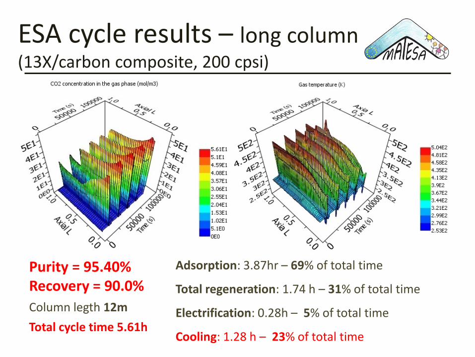
ESA cycle results – long column(13X/carbon composite, 200 cpsi)
Purity = 95.40%Recovery = 90.0%Column legth 12mTotal cycle time 5.61h
Adsorption: 3.87hr – 69% of total time
Total regeneration: 1.74 h – 31% of total time
Electrification: 0.28h – 5% of total time
Cooling: 1.28 h – 23% of total time
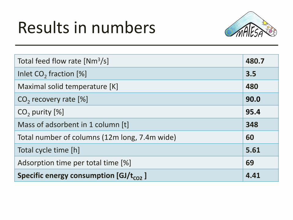
Results in numbers
Total feed flow rate [Nm3/s] 480.7Inlet CO2 fraction [%] 3.5Maximal solid temperature [K] 480CO2 recovery rate [%] 90.0CO2 purity [%] 95.4Mass of adsorbent in 1 column [t] 348Total number of columns (12m long, 7.4m wide) 60Total cycle time [h] 5.61Adsorption time per total time [%] 69Specific energy consumption [GJ/tCO2 ] 4.41
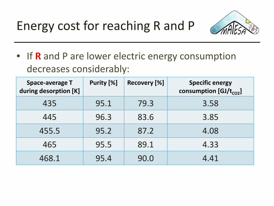
Energy cost for reaching R and P
• If R and P are lower electric energy consumption decreases considerably: Space-average T
during desorption [K]Purity [%] Recovery [%] Specific energy
consumption [GJ/tCO2]
435 95.1 79.3 3.58445 96.3 83.6 3.85
455.5 95.2 87.2 4.08465 95.5 89.1 4.33
468.1 95.4 90.0 4.41
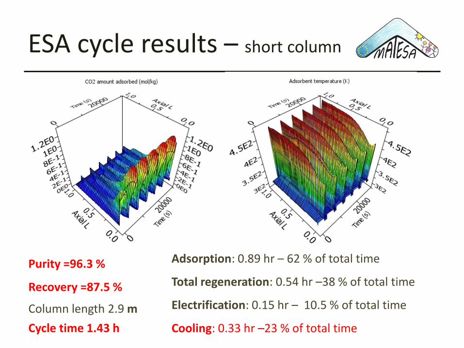
ESA cycle results – short column
Purity =96.3 %
Recovery =87.5 %
Column length 2.9 mCycle time 1.43 h
Adsorption: 0.89 hr – 62 % of total time
Total regeneration: 0.54 hr –38 % of total time
Electrification: 0.15 hr – 10.5 % of total time
Cooling: 0.33 hr –23 % of total time

Results in numbers
Total feed flow rate [Nm3/s] 480.7Inlet CO2 fraction [%] 3.5Maximal solid temperature [K] 480CO2 recovery rate [%] 87.5CO2 purity [%] 96.2Mass of adsorbent per column [t] 86.94
Total number of columns (3m long, 7.4m wide) 60Total cycle time [h] 1.43Adsorption time per total time [%] 62Specific energy consumption [GJ/tCO2 ] 4.62
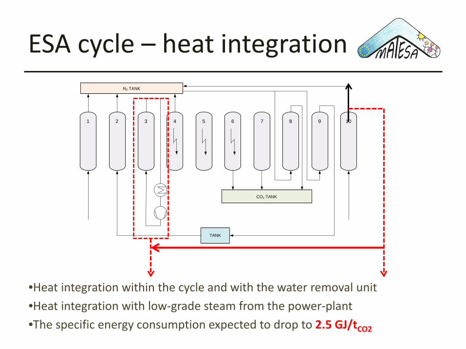
ESA cycle – heat integration
1 2 3 4 5 6 7 8 9 10
CO2 TANK
N2 TANK
TANK
•Heat integration within the cycle and with the water removal unit•Heat integration with low-grade steam from the power-plant•The specific energy consumption expected to drop to 2.5 GJ/tCO2
Summary• Within MATESA project, models for ESA process, suitable for
complex cycle simulations and optimisation, have been developed and exploited
• The ESA cycle simulations show that the requirements of high purity (>95%) and recovery (>90%) can be achieved, though through complex cycle design with a number of steps and recycles
• The results indicate that the ESA process based on zeolite or MOF-carbon composite monoliths can be an alternative to absorption based processes for CO2 capture
• Further impovements trough further material development and optimisation and energy integration are foreseen