es593.1-d interface module (1xetk, 4xcan, 2xethernet) · pdf file · 2018-01-24the...
TRANSCRIPT
ES593.1-DInterface Module (1xETK, 4xCAN, 2xEthernet)User’s Guide

2
Copyright
The data in this document may not be altered or amended without special noti-fication from ETAS GmbH. ETAS GmbH undertakes no further obligation in rela-tion to this document. The software described in it can only be used if the customer is in possession of a general license agreement or single license. Using and copying is only allowed in concurrence with the specifications stipulated in the contract.
Under no circumstances may any part of this document be copied, reproduced, transmitted, stored in a retrieval system or translated into another language without the express written permission of ETAS GmbH.
© Copyright 2017 ETAS GmbH, Stuttgart
The names and designations used in this document are trademarks or brands belonging to the respective owners.
ES593.1-D - User’s Guide R08 EN - 12.2017

Contents
ETAS Contents
1 About this Manual . . . . . . . . . . . . . . . . . . . . . . . . . . . . . . . . . . . . . . . . . . . . . . . . . 61.1 Identification of Safety Notices . . . . . . . . . . . . . . . . . . . . . . . . . . . . . . . . . . . 61.2 Presentation of Information . . . . . . . . . . . . . . . . . . . . . . . . . . . . . . . . . . . . . 61.3 Scope of Supply . . . . . . . . . . . . . . . . . . . . . . . . . . . . . . . . . . . . . . . . . . . . . . 71.4 Additional Information . . . . . . . . . . . . . . . . . . . . . . . . . . . . . . . . . . . . . . . . . 7
2 Basic Safety Notices . . . . . . . . . . . . . . . . . . . . . . . . . . . . . . . . . . . . . . . . . . . . . . . . 82.1 General Safety Information . . . . . . . . . . . . . . . . . . . . . . . . . . . . . . . . . . . . . . 82.2 Requirements for Users and Duties for Operators . . . . . . . . . . . . . . . . . . . . . 82.3 Intended Use . . . . . . . . . . . . . . . . . . . . . . . . . . . . . . . . . . . . . . . . . . . . . . . . 8
3 Hardware Description . . . . . . . . . . . . . . . . . . . . . . . . . . . . . . . . . . . . . . . . . . . . . . 123.1 Overview . . . . . . . . . . . . . . . . . . . . . . . . . . . . . . . . . . . . . . . . . . . . . . . . . . 123.2 Features . . . . . . . . . . . . . . . . . . . . . . . . . . . . . . . . . . . . . . . . . . . . . . . . . . . 123.3 Housing . . . . . . . . . . . . . . . . . . . . . . . . . . . . . . . . . . . . . . . . . . . . . . . . . . . 133.4 Interfaces . . . . . . . . . . . . . . . . . . . . . . . . . . . . . . . . . . . . . . . . . . . . . . . . . . 14
3.4.1 Front Panel . . . . . . . . . . . . . . . . . . . . . . . . . . . . . . . . . . . . . . . . . . 143.4.2 Back Panel. . . . . . . . . . . . . . . . . . . . . . . . . . . . . . . . . . . . . . . . . . . 14
3.5 LEDs . . . . . . . . . . . . . . . . . . . . . . . . . . . . . . . . . . . . . . . . . . . . . . . . . . . . . . 153.5.1 Flash Codes . . . . . . . . . . . . . . . . . . . . . . . . . . . . . . . . . . . . . . . . . . 153.5.2 Operational State of the Module . . . . . . . . . . . . . . . . . . . . . . . . . . 153.5.3 Functional State of Individual Interfaces . . . . . . . . . . . . . . . . . . . . . 16
4 Functional Description. . . . . . . . . . . . . . . . . . . . . . . . . . . . . . . . . . . . . . . . . . . . . . 194.1 Block Diagram . . . . . . . . . . . . . . . . . . . . . . . . . . . . . . . . . . . . . . . . . . . . . . 194.2 Power Supply (7-29V DC) . . . . . . . . . . . . . . . . . . . . . . . . . . . . . . . . . . . . . . 194.3 Ethernet Switch . . . . . . . . . . . . . . . . . . . . . . . . . . . . . . . . . . . . . . . . . . . . . 19
4.3.1 Host Port (HOST) . . . . . . . . . . . . . . . . . . . . . . . . . . . . . . . . . . . . . . 204.3.2 Ethernet Ports (ETH1 and ETH2). . . . . . . . . . . . . . . . . . . . . . . . . . . 20
4.4 ETK Interface (ETK) . . . . . . . . . . . . . . . . . . . . . . . . . . . . . . . . . . . . . . . . . . . 20
ES593.1-D - User’s Guide 3

4
Contents ETAS
4.4.1 Initialization. . . . . . . . . . . . . . . . . . . . . . . . . . . . . . . . . . . . . . . . . . 214.4.2 Operating Modes . . . . . . . . . . . . . . . . . . . . . . . . . . . . . . . . . . . . . 21
4.5 CAN Interface (CAN1/CAN3, CAN2/CAN4) . . . . . . . . . . . . . . . . . . . . . . . . . 224.5.1 Operating Modes . . . . . . . . . . . . . . . . . . . . . . . . . . . . . . . . . . . . . 224.5.2 Feature . . . . . . . . . . . . . . . . . . . . . . . . . . . . . . . . . . . . . . . . . . . . . 224.5.3 "Wake-Up" Function. . . . . . . . . . . . . . . . . . . . . . . . . . . . . . . . . . . 224.5.4 „CAN Pre-Buffering“ Function (Buffering of CAN Frames) . . . . . . . 224.5.5 Bus Terminating Resistor . . . . . . . . . . . . . . . . . . . . . . . . . . . . . . . . 22
4.6 Time Synchronization . . . . . . . . . . . . . . . . . . . . . . . . . . . . . . . . . . . . . . . . . 234.7 "Wake-Up" Function . . . . . . . . . . . . . . . . . . . . . . . . . . . . . . . . . . . . . . . . . 234.8 Firmware Update . . . . . . . . . . . . . . . . . . . . . . . . . . . . . . . . . . . . . . . . . . . . 24
5 Getting Started . . . . . . . . . . . . . . . . . . . . . . . . . . . . . . . . . . . . . . . . . . . . . . . . . . . 255.1 Assembly and Locking . . . . . . . . . . . . . . . . . . . . . . . . . . . . . . . . . . . . . . . . 25
5.1.1 General Installation Recommendations . . . . . . . . . . . . . . . . . . . . . 255.1.2 Fixing a Module onto a Carrier System. . . . . . . . . . . . . . . . . . . . . . 255.1.3 Connecting Several Modules Mechanically . . . . . . . . . . . . . . . . . . 26
5.2 Applications . . . . . . . . . . . . . . . . . . . . . . . . . . . . . . . . . . . . . . . . . . . . . . . . 285.3 Wiring . . . . . . . . . . . . . . . . . . . . . . . . . . . . . . . . . . . . . . . . . . . . . . . . . . . . 29
5.3.1 “HOST” Port . . . . . . . . . . . . . . . . . . . . . . . . . . . . . . . . . . . . . . . . 295.3.2 “7-29V” Port . . . . . . . . . . . . . . . . . . . . . . . . . . . . . . . . . . . . . . . . 295.3.3 “ETH1” and “ETH2” Port . . . . . . . . . . . . . . . . . . . . . . . . . . . . . . . 30
5.4 Configuring the ES593.1-D . . . . . . . . . . . . . . . . . . . . . . . . . . . . . . . . . . . . . 325.4.1 Web Interface . . . . . . . . . . . . . . . . . . . . . . . . . . . . . . . . . . . . . . . . 325.4.2 Launching the ES593.1-D Web Interface . . . . . . . . . . . . . . . . . . . . 325.4.3 Configuring the “Wake Up” Function . . . . . . . . . . . . . . . . . . . . . . 32
6 Troubleshooting Problems. . . . . . . . . . . . . . . . . . . . . . . . . . . . . . . . . . . . . . . . . . . 336.1 Error LEDs . . . . . . . . . . . . . . . . . . . . . . . . . . . . . . . . . . . . . . . . . . . . . . . . . . 336.2 Troubleshooting ES593.1-D Problems . . . . . . . . . . . . . . . . . . . . . . . . . . . . . 336.3 Problems and Solutions . . . . . . . . . . . . . . . . . . . . . . . . . . . . . . . . . . . . . . . . 35
6.3.1 Network Adapter cannot be selected via Network Manager. . . . . . 356.3.2 Search for Ethernet Hardware Fails . . . . . . . . . . . . . . . . . . . . . . . . 366.3.3 Personal Firewall Blocks Communication . . . . . . . . . . . . . . . . . . . . 37
7 Technical Data . . . . . . . . . . . . . . . . . . . . . . . . . . . . . . . . . . . . . . . . . . . . . . . . . . . 427.1 General Data . . . . . . . . . . . . . . . . . . . . . . . . . . . . . . . . . . . . . . . . . . . . . . . 42
7.1.1 Product Labeling . . . . . . . . . . . . . . . . . . . . . . . . . . . . . . . . . . . . . . 427.1.2 Fulfilled Standards and Norms . . . . . . . . . . . . . . . . . . . . . . . . . . . . 437.1.3 Environmental Conditions . . . . . . . . . . . . . . . . . . . . . . . . . . . . . . 437.1.4 Maintenance the Product . . . . . . . . . . . . . . . . . . . . . . . . . . . . . . . 437.1.5 Cleaning the Product. . . . . . . . . . . . . . . . . . . . . . . . . . . . . . . . . . . 437.1.6 Mechanical Data . . . . . . . . . . . . . . . . . . . . . . . . . . . . . . . . . . . . . . 44
7.2 RoHS Conformity . . . . . . . . . . . . . . . . . . . . . . . . . . . . . . . . . . . . . . . . . . . . 447.2.1 European Union . . . . . . . . . . . . . . . . . . . . . . . . . . . . . . . . . . . . . . 447.2.2 China . . . . . . . . . . . . . . . . . . . . . . . . . . . . . . . . . . . . . . . . . . . . . . 44
7.3 CE Labeling . . . . . . . . . . . . . . . . . . . . . . . . . . . . . . . . . . . . . . . . . . . . . . . . 447.4 Taking the Product Back and Recycling . . . . . . . . . . . . . . . . . . . . . . . . . . . . 447.5 Declarable Substances . . . . . . . . . . . . . . . . . . . . . . . . . . . . . . . . . . . . . . . . 457.6 Use of Open Source Software . . . . . . . . . . . . . . . . . . . . . . . . . . . . . . . . . . . 45
ES593.1-D - User’s Guide

ETAS Contents
7.7 System Requirements . . . . . . . . . . . . . . . . . . . . . . . . . . . . . . . . . . . . . . . . . 457.7.1 Hardware . . . . . . . . . . . . . . . . . . . . . . . . . . . . . . . . . . . . . . . . . . . 457.7.2 Supported Applications and Software Requirements . . . . . . . . . . . 46
7.8 Electrical Data . . . . . . . . . . . . . . . . . . . . . . . . . . . . . . . . . . . . . . . . . . . . . . . 477.8.1 Power Supply . . . . . . . . . . . . . . . . . . . . . . . . . . . . . . . . . . . . . . . . 477.8.2 Host Interface (HOST) . . . . . . . . . . . . . . . . . . . . . . . . . . . . . . . . . 477.8.3 Ethernet Interfaces (ETH1 and ETH2) . . . . . . . . . . . . . . . . . . . . . . . 487.8.4 ETK Interface (ETK) . . . . . . . . . . . . . . . . . . . . . . . . . . . . . . . . . . . 497.8.5 CAN Interfaces (CAN1/CAN3 and CAN2/CAN4). . . . . . . . . . . . . . . 49
7.9 Pin Assignment . . . . . . . . . . . . . . . . . . . . . . . . . . . . . . . . . . . . . . . . . . . . . 507.9.1 Power Supply Interface (7-29V) . . . . . . . . . . . . . . . . . . . . . . . . . . . 507.9.2 Host Interface (HOST) . . . . . . . . . . . . . . . . . . . . . . . . . . . . . . . . . . 507.9.3 Ethernet Interfaces (ETH1 and ETH2) . . . . . . . . . . . . . . . . . . . . . . . 517.9.4 ETK Interface (ETK) . . . . . . . . . . . . . . . . . . . . . . . . . . . . . . . . . . . . 517.9.5 CAN Interface (CAN1/CAN3) . . . . . . . . . . . . . . . . . . . . . . . . . . . . . 527.9.6 CAN Interface (CAN2/CAN4) . . . . . . . . . . . . . . . . . . . . . . . . . . . . . 52
8 Cable and Accessories. . . . . . . . . . . . . . . . . . . . . . . . . . . . . . . . . . . . . . . . . . . . . . 538.1 Cable for the "7-29 V DC" Connection . . . . . . . . . . . . . . . . . . . . . . . . . . . 53
8.1.1 CBP120 Cable . . . . . . . . . . . . . . . . . . . . . . . . . . . . . . . . . . . . . . . . 548.1.2 CBP1205 Cable . . . . . . . . . . . . . . . . . . . . . . . . . . . . . . . . . . . . . . . 55
8.2 HOST Interface Cable . . . . . . . . . . . . . . . . . . . . . . . . . . . . . . . . . . . . . . . . . 568.3 ETH1 und ETH2 Interface Cable . . . . . . . . . . . . . . . . . . . . . . . . . . . . . . . . . 56
8.3.1 Ethernet Connection and Power Supply Cable . . . . . . . . . . . . . . . . 568.3.2 Ethernet Connection Cable . . . . . . . . . . . . . . . . . . . . . . . . . . . . . . 588.3.3 Ethernet Connection Adapter Cable . . . . . . . . . . . . . . . . . . . . . . . 59
8.4 ETK Interface Cable . . . . . . . . . . . . . . . . . . . . . . . . . . . . . . . . . . . . . . . . . . 608.5 CAN/LIN Interface Cable and Adapter . . . . . . . . . . . . . . . . . . . . . . . . . . . . . 61
8.5.1 CAN Interface Cable . . . . . . . . . . . . . . . . . . . . . . . . . . . . . . . . . . . 618.5.2 CBCFI100 Cable . . . . . . . . . . . . . . . . . . . . . . . . . . . . . . . . . . . . . . 638.5.3 CAN Termination Resistor . . . . . . . . . . . . . . . . . . . . . . . . . . . . . . . 66
9 Ordering Information . . . . . . . . . . . . . . . . . . . . . . . . . . . . . . . . . . . . . . . . . . . . . . 679.1 ES593.1-D . . . . . . . . . . . . . . . . . . . . . . . . . . . . . . . . . . . . . . . . . . . . . . . . . 67
9.1.1 ES593.1-D with CBP120 Power Supply Cable . . . . . . . . . . . . . . . 679.1.2 ES593.1-D with CBP1205 Power Supply Cable . . . . . . . . . . . . . . 67
9.2 Cable and Accessoires . . . . . . . . . . . . . . . . . . . . . . . . . . . . . . . . . . . . . . . 689.2.1 Cable for the "7-29 V DC" Connection . . . . . . . . . . . . . . . . . . . . . 689.2.2 "HOST" Interface Cable . . . . . . . . . . . . . . . . . . . . . . . . . . . . . . . . 689.2.3 "ETH1 and ETH2" Interface Cable . . . . . . . . . . . . . . . . . . . . . . . . . 689.2.4 "ETK" Interface Cable . . . . . . . . . . . . . . . . . . . . . . . . . . . . . . . . . 699.2.5 "CAN/LIN" Interface Cable and Adapter . . . . . . . . . . . . . . . . . . . . 709.2.6 Housing Accessories . . . . . . . . . . . . . . . . . . . . . . . . . . . . . . . . . . . 709.2.7 Software . . . . . . . . . . . . . . . . . . . . . . . . . . . . . . . . . . . . . . . . . . . 70
10 ETAS Contact Addresses . . . . . . . . . . . . . . . . . . . . . . . . . . . . . . . . . . . . . . . . . . . . 71
Figures . . . . . . . . . . . . . . . . . . . . . . . . . . . . . . . . . . . . . . . . . . . . . . . . . . . . . . . . . 72
Index . . . . . . . . . . . . . . . . . . . . . . . . . . . . . . . . . . . . . . . . . . . . . . . . . . . . . . . . . . 74
ES593.1-D - User’s Guide 5
6
About this Manual ETAS
1 About this Manual
This chapter contains information about the following topics:
• "Identification of Safety Notices" on page 6,
• "Presentation of Information" on page 6,
• "Scope of Supply" on page 7,
• "Additional Information" on page 7.
1.1 Identification of Safety Notices
The safety notices contained in this manual are identified with the danger symbol shown below:
The safety notices shown below are used for this purpose. They provide notes to extremely important information. Please read this information carefully.
1.2 Presentation of Information
All activities to be performed by the user are presented in a "Use Case" format. That is, the goal to be accomplished is briefly defined in the heading, and the respective steps required for reaching this goal are then presented in a list. The presentation looks as follows:
Goal definition:
any advance information...
• Step 1
Any explanation for step 1...
• Step 2
Any explanation for step 2...
• Step 3
Any explanation for step 3...
DANGER!
indicates an immediate danger with a high risk of death or serious injury, if not avoided.
WARNING!
indicates a possible danger with moderate risk of death or (serious) injury, if not avoided.
CAUTION!
identifies a hazard with low risk that could result in minor or medium physical injuries or property damages if not avoided.
ES593.1-D - User’s Guide
ETAS About this Manual
Any concluding comments...
Typographical conventions
The following typographical conventions are used:
Important notes for the user are presented as follows:
1.3 Scope of Supply
Prior to the initial commissioning of the module, please check whether the mod-ule was delivered with all required components and cables (see chapter 9.1 on page 67).
Additional cables and adapters can be obtained separately from ETAS. A list of available accessories and their order designation is located in chapter "Cable and Accessoires" on page 68 of this manual or in the ETAS product catalog.
1.4 Additional Information
The configuration instructions for the module under INCA can be found in the corresponding software documentation.
Bold Labels of the device
Italic Particularly important text passages
Note
Important note for the user.
ES593.1-D - User’s Guide 7

8
Basic Safety Notices ETAS
2 Basic Safety Notices
This chapter contains information about the following topics:
• "General Safety Information" on page 8,
• "Requirements for Users and Duties for Operators" on page 8,
• "Intended Use" on page 8.
2.1 General Safety Information
Please observe the Product Safety Notices ("ETAS Safety Notice") and the follow-ing safety notices to avoid health issues or damage to the device.
ETAS GmbH does not assume any liability for damages resulting from improper handling, unintended use or non-observance of the safety precautions.
2.2 Requirements for Users and Duties for Operators
The product may be assembled, operated and maintained only if you have the necessary qualification and experience for this product. Improper use or use by a user without sufficient qualification can lead to damages or injuries to one's health or damages to property.
General safety at work
The existing regulations for safety at work and accident prevention must be fol-lowed. All applicable regulations and statutes regarding operation must be strictly followed when using this product.
2.3 Intended Use
Application area of the product
This product was developed and approved for applications in the automotive sector. The module is suitable for use in interiors, in the passenger cell or in the trunk of vehicles. The module is not suitable for installation in the engine com-partment and similar environments. For use in other application areas, please contact your ETAS contact partner.
Requirements for the technical state of the product
The product is designed in accordance with state-of-the-art technology and rec-ognized safety rules. The product may be operated only in a technically flawless condition and according to the intended purpose and with regard to safety and dangers as stated in the respective product documentation. If the product is not used according to its intended purpose, the protection of the product may be impaired.
Note
Carefully read the documentation (Product Safety Advice and this User's Guide) that belongs to the product prior to the startup.
ES593.1-D - User’s Guide

ETAS Basic Safety Notices
Requirements for operation
• Use the product only according to the specifications in the corresponding User's Guide. With any deviating operation, the product safety is no lon-ger ensured.
• Observe the requirements on the ambient conditions.
• Do not use the product in a wet or damp environment.
• Do not use the product in potentially explosive atmospheres.
Electrical safety and power supply
• Observe the regulations applicable at the operating location concerning electrical safety as well as the laws and regulations concerning work safety!
• Connect only current circuits with safety extra-low voltage in accordance with EN 61140 (degree of protection III) to the connections of the module.
• Ensure that the connection and setting values are being followed (see the information in the chapter "Technical data").
• Do not apply any voltages to the connections of the module that do not correspond to the specifications of the respective connection.
Power supply
• The power supply for the product must be safely disconnected from the supply voltage. For example, use a car battery or a suitable lab power sup-ply.
• Use only lab power supplies with double protection to the supply network (with double insulation/reinforced insulation (DI/ RI)).
• The lab power supply must be approved for an operating altitude of 5000 m and for an ambient temperature of up to 70 °C.
• In regular operation of the modules as well as very long standby opera-tion, a discharge of the vehicle battery is possible.
Connection to the power supply
• The power cable must not be connected directly to the vehicle battery or lab power supply, but via a fuse of up to 20 A.
• Ensure that the connections of the lab power supply, the power supply at the module and the vehicle battery are easily accessible!
• Route the power cord in such a way that it is protected against abrasion, damages, deformation and kinking. Do not place any objects on the power cord!
DANGER!
Dangerous electrical voltage!Connect the power cable only with a suitable vehicle battery or with a suitable lab power supply! The connection to power outlets is not allowed!To prevent an inadvertent insertion in power outlets, ETAS recom-mends to equip the power cables with safety banana plugs in areas with power outlets.
ES593.1-D - User’s Guide 9
10
Basic Safety Notices ETAS
Disconnecting from the power supply
The module does not have an operating voltage switch. The module can be de-energized as follows:
• Disconnecting the module from the lab power supply
– Separating device is the lab plug of the power cord or
– Separating device is the plug of the power cord at the connection of the module
• Disconnecting the module from the vehicle battery
– Separating device is the lab plug of the power cord or
– Separating device is the plug of the power cord at the connection of the module
• Disconnecting the vehicle battery.
Approved cables
• Use exclusively ETAS cables at the connections of the module!
• Adhere to the maximum permissible cable lengths!
• Do not use any damaged cables! Cables may be repaired only by ETAS!
• Never apply force to insert a plug into a socket. Ensure that there is no contamination in and on the connection, that the plug fits the socket, and that you correctly aligned the plugs with the connection.
Requirements for the location
• Position the module or the module stack on a smooth, level and solid underground.
• The module or the module stack must always be securely fastened.
Fixing the modules on a carrier system
• When selecting the carrier system, observe the static and dynamic forces that could be created by the module or the module stack on the carrier system.
Requirements on the ventilation
• Keep the module away from heat sources and protect it against direct exposure to the sun.
• The free space above and behind the module must be selected so that sufficient air circulation is ensured.
Assembling (interconnecting) the modules
• Prior to assembling (interconnecting) or separating a module stack, the modules must be disconnected from the supply voltage or they have to be in the standby operating mode.
Transport
• Stack and connect the modules only at the location of the startup!
• Do not transport the modules at the cable of the module or any other cables.
ES593.1-D - User’s Guide
ETAS Basic Safety Notices
Maintenance
The product is maintenance-free.
Repair
If an ETAS hardware product should require a repair, return the product to ETAS.
Cleaning the module housing
• Use a dry or lightly moistened, soft, lint-free cloth for cleaning the module housing.
• Do not user any sprays, solvents or abrasive cleaners which could damage the housing.
• Ensure that no moisture enters the housing. Never spray cleaning agents directly onto the module.
Ambient conditions
The housing and the connectors of the module as well as the plug connectors of the cables meet the degree of protection IP30.
Opening the module
Potential equalization
Cabling
For detailed information about cabling, see the User's Guide of the module.
CAUTION!
Damage to the module and loss of properties based on IP30!Do not open or change the module housing!Work on the module housing may only be performed by ETAS.
CAUTION!
Potential equalization in the vehicle is possible via the shield of the connecting cables of the modules!Install the modules only at locations with the same electrical potential or isolate the modules from the installation location.
ES593.1-D - User’s Guide 11

12
Hardware Description ETAS
3 Hardware Description
This chapter provides you with an overview of the ES593.1-D with information on the housing, serial number, ports and LEDs.
3.1 Overview
The ES59x line is a range of powerful ECU and bus interface modules. The ES59x modules have an upstream Ethernet interface that guarantees data exchange with the host PC or with a Drive Recorder. The ES593.1-D module has two down-stream Ethernet interfaces that can be connected with ES59x, ES600, measure-ment and interface modules.
Fig. 3-1 View of the Device
Individual measurement, calibration and rapid prototyping modules are easy to combine with ES59x line modules. ECUs that have an XETK, or ECUs that have their own Ethernet interface can be connected directly with an ES593.1-D mod-ule and communicate with INCA via Ethernet. The ES593.1-D has the ECU inter-faces ETK and CAN.
Two of the four CAN interfaces additionally offer a "Wake-Up" function and buffer CAN messages until a ES720 Drive Recorder connected to the ES593.1-Dstarts the data recording.
If necessary, systems can be cascaded using ES59x nodes. The Ethernet switch guarantees the time-synchronous sampling of all measurement channels – even in sizeable module networks.
The ES593.1-D module and the relevant cables are intended for use in the lab, on the test bench and in the passenger cell of vehicles.
3.2 Features
Overview of the major features of the ES593.1-D:
• Ethernet switch with a 10/100 Mbit/s data rate:
– One host port (upstream)
– Two ports for compatible modules (downstream)
– Can be cascaded up to 15 modules
– Automatic standby function
ES593.1-D - User’s Guide

ETAS Hardware Description
– Precise synchronization of all connected modules and their measure-ment channels
• ETK interface
– Measure and calibration applications
• Four independent CAN interfaces:
– CAN High Speed (max. 1 MBaud)
– CAN protocols CAN V2.0a (Standard Identifier with 11-bit) and CAN V2.0b (Extended Identifier with 29-bit)
– "Wake-Up" function (two CAN interfaces)
– Buffering of CAN messages for applications with the ES720 Drive Recorder (two CAN interfaces)
Additional features of the module:
• Module suitable for use in automotive applications; suitable for use in the development environment and in the vehicle on test drives.
– Channels galvanically isolated from each other, from the device ground and from the supply voltage
– Not sensitive to environmental conditions (temperature, EMC)
– Wide supply voltage range
– High mechanical stability and durability
• Part of the ETAS Tool Suite
For the complete technical data of the ES593.1-D, refer to the chapter "Technical Data" on page 42.
3.3 Housing
Standard housing with interfaces on the front and rear of the device is used for the ES593.1-D. The sturdy metal housing of the ES593.1-D has nonskid plastic feet.
It can be easily screwed onto a carrier system for installation in a vehicle or in the lab. The housings of this device family can also quickly and easily be connected to one another (see the chapter 5.1 on page 25).
The ES593.1-D is intended for use in the lab, on the test bench and in the pas-senger cell of vehicles.
ES593.1-D - User’s Guide 13

14
Hardware Description ETAS
3.4 Interfaces
3.4.1 Front Panel
The following interfaces are on the front panel of the ES593.1-D:
• HOST (Ethernet, SYNC-IN)
• ETK (1 x ETK)
• ETH1 (Ethernet, SYNC-OUT)
• ETH2 (Ethernet, SYNC-OUT)
• CAN2/CAN4 (1 x CAN und 1 x CAN)
• CAN1/CAN3 (1 x CAN und 1 x CAN)
Fig. 3-2 Front Panel
3.4.2 Back Panel
The interface 7-29V (power supply) is on the back panel of the ES593.1-D.
Fig. 3-3 Back Panel
7‐29V 7A
ES593.1-D - User’s Guide
ETAS Hardware Description
3.5 LEDs
3.5.1 Flash Codes
The ES593.1-D is equipped with LEDs, which indicate the operational state of the module, as well as with LEDs which display the function of individual interfaces. The following flash codes are used for the LEDs:
Fig. 3-4 Flash Codes
3.5.2 Operational State of the Module
Four LEDs can be found top left on the front panel of the ES593.1-D(see Fig. 3-2 on page 14). They indicate operational, error and synchronization states.
• ON: power supply and operational state
• ER: error states or firmware update
• °C: temperature inside the housing
• SYNC: synchronization function of the module (master or slave) and the synchronization state
• MODE: function "Pre-Buffering" (interfaces CAN1 and CAN2)
LED Display Operational State
ON Green The module is powered on.
Green, flashing(Flash code 3)
The module is on “Standby”, the power consumption is minimal. The module needs a wakeup event to enter the nor-mal operation mode.
Off The module is not powered.
Flash code 1On
Off
Of f
On
LED
1 3 42 t (s)
Of f
On
Off
On
Off
On
Flash code 2
Flash code 4
Flash code 5
Flash code 3
ES593.1-D - User’s Guide 15

16
Hardware Description ETAS
3.5.3 Functional State of Individual Interfaces
LEDs assigned to the interfaces of the module can be found on the front panel of the device (see Fig. 3-2 on page 14). If the ES593.1-D is powered on (opera-tional state "On") they indicate the following functional states at the assigned interfaces:
ER Red Module is currently booting or booting was unsuccessful.
Red, flashing(Flash code 1)
Internal device software error, core file created.
Red, flashing(Flash code 2)
Firmware update is being executed.
Off No error
°C Red Temperature inside the housing has exceeded the critical level and the mod-ule powered down; the module is pow-ered on again if the temperature inside the housing has reached the normal operational range
Red(Flash code 2)
Temperature inside the housing has reached a critical level. The module does not shut down any functionality.
Off Temperature inside the housing is in nor-mal operational range.
SYNC Blue, flashing (Flash code 4), fully bright
The module is a synchronization master; the module is not synchronized externally
Blue, flashing (Flash code 5), semi and fully bright alternately
The module is a synchronization slave; the module is synchronized externally at the HOST or at the ETH1 or at the ETH2 port
Off No synchronization
MODE Green Function "CAN Pre-Buffering" for the interfaces CAN1 and/ or CAN2 is acti-vated in INCA (HWC)
Off Function "CAN Pre-Buffering" for the interfaces CAN1 and/ or CAN2 is deacti-vated in INCA (HWC) or in the web inter-face
LED Display Operational State
ES593.1-D - User’s Guide

ETAS Hardware Description
HOST Interface
An LED HOST is assigned to the interface HOST.
ETK Interface
An LED ETK is assigned to the interface ETK.
ETH1 Interface
An LED ETH1 and an LED POUT are assigned to the interface ETH1.
ETH2 Interface
An LED ETH2 and an LED POUT are assigned to the interface ETH1.
LED Display Functional State
HOST Yellow, flashing Communication at the interface HOST
Off Communication interrupted
LED Display Functional State
ETK Yellow, flashing Communication at the interface ETK
Off Communication interrupted
LED Display Functional State
ETH1 Yellow, flashing Communication at the interface ETH1
Off Communication interrupted
POUT Green Power supply output at the interface ETH1 is switched on
Red Overload by connected module at the power supply output at the interface ETH1
Off Power supply output at the interface ETH1 is switched off
LED Display Functional State
ETH2 Yellow, flashing Communication at the interface ETH2
Off Communication interrupted
POUT Green Power supply output at the interface ETH2 is switched on
Red Overload by connected module at the power supply output at the interface ETH2
Off Power supply output at the interface ETH2 is switched off
ES593.1-D - User’s Guide 17

18
Hardware Description ETAS
CAN2/CAN4 Interface
An LED CAN2 is assigned to the interface CAN2 and an LED CAN4 is assigned to the interface CAN4.
CAN1/CAN3 Interface
An LED CAN1 is assigned to the interface CAN1 and an LED CAN3 is assigned to the interface LIN1.
LED Display Functional State
CAN2 Yellow, flashing Communication at the interface CAN2
Off Communication interrupted
CAN4 Yellow, flashing Communication at the interface CAN4
Off Communication interrupted
LED Display Functional State
CAN1 Yellow, flashing Communication at the interface CAN1
Off Communication interrupted
CAN3 Yellow, flashing Communication at the interface CAN3
Off Communication interrupted
ES593.1-D - User’s Guide

ETAS Functional Description
4 Functional Description
This chapter describes the block diagram, power supply, Ethernet switch, module network, time synchronization, ECU interfaces and the firmware update.
4.1 Block Diagram
Fig. 4-1 Block Diagram
To fulfill the operation demands in the vehicle, the interfaces of the ES593.1-D are each routed to an Lemo socket.
4.2 Power Supply (7-29V DC)
The power supply interface (7-29V DC) is routed to a 2-pin connector (Lemo socket) on the back panel of the module. Power is supplied to the module via an external power supply or vehicle battery.
When the ES593.1-D is connected to the operating voltage and there is an Ether-net connection at HOST, the module boots. If there is no Ethernet connection, the module changes to “Standby.”
4.3 Ethernet Switch
The integrated Ethernet switch is used for the connection of the ES593.1-D mod-ule and other measurement or interface modules to a user PC. Data from the connected modules is acquired synchronously (ETAS device synchronization, see chapter 4.6 on page 23). The Ethernet switch can be cascaded with other net-work modules so that you can create larger blocks of measurement and interface modules.
The switch is equipped with Ethernet interfaces in accordance with the standard 10/100BaseT that can be operated with either 10 or 100 Mbit/s, half or full duplex. The switchover takes place automatically.
Note
The ES593.1-D must be physically disconnected from all supply voltages so the module is not supplied with power.
ES593-D
ETH 110/100 MBit
HOST
CPU FlashDDR2RAM
Fast BootRAM
ETK
Transceiver8/100 MBit/s
ETKController
Ethernet Phy
Ethernet Phy
Ethernet Phy
Time Synchronization UnitS
YN
C O
UT
SY
NC
IN
Power Supply
EthernetTraffic
Detection
LED
CANController
CAN Transceiver
High Speed
CAN2/CAN4CANController
CAN1/CAN3
ETH 210/100 MBit
CANController
CANController
CAN Transceiver
High Speed
CAN Transceiver
High Speed
CAN Transceiver
High Speed
Fast Boot & Prebuffer
7..29V DC
Ethe
rnet
Sw
itch
ES593.1-D - User’s Guide 19
20
Functional Description ETAS
All switch interfaces are galvanically isolated from each other and from the power supply.
4.3.1 Host Port (HOST)
The upstream Ethernet interface HOST combines the ES593.1-D module with the user PC or with a downstream Ethernet interface of a further module. This inter-face allows the ETAS software tools access to the connected modules.
"Wake-Up" Function
The Ethernet interface HOST supports the "Wake-Up" function (see chapter 4.7 on page 23).
Compatible Modules
A list of compatible modules can be found in chapter 7.8.2 on page 47.
4.3.2 Ethernet Ports (ETH1 and ETH2)
The ES593.1-D module provides two downstream Ethernet interfaces for further modules. ECUs that have an XETK or their own Ethernet interface can be con-nected directly with a ES593.1-D module and communicate with the calibration software via XCP-on-Ethernet.
Module Network
The downstream Ethernet interfaces ETH1 and ETH2 connect the ES593.1-D module to other ES600 modules, measurement, calibration and rapid prototyp-ing modules. Large blocks of measurement and interfaces modules can be cre-ated as the modules can be cascaded.
Power Supply of connected Modules
The ES593.1-D module can additionally power ES4xx modules, ES6xx modules or XETKs via the Ethernet connection cable. Take a note of the maximum output current at the Ethernet ports when the modules are cascaded.
Other modules connected via Ethernet cable must be wired separately to the power supply.
"Wake-Up" Function
The Ethernet interfaces ETH1 and ETH2 support the "Wake-Up" function (see chapter 4.7 on page 23).
Compatible Modules
A list of compatible modules can be found in chapter 7.8.3 on page 48.
4.4 ETK Interface (ETK)
The ES593.1-D has one ETK interface which is routed to a 4-pin ETK connector (Lemo socket) on the front panel. The interface is galvanically isolated from the other interfaces of the ES593.1-D.
ES593.1-D - User’s Guide

ETAS Functional Description
The ETK interface of the ES593.1-D supports the ECU application via the emula-tor test probe (ETK).
4.4.1 Initialization
If an ETK type supported by the ES593.1-D is connected to the ETK interface it is recognized automatically. The ETK interface is automatically initialized.
If an ETK type which is not supported by the ES593.1-D is connected to the ETK interface the overall system behaves, as if no ETK is connected. No specific error message is generated.
4.4.2 Operating Modes
In addition to single transfer for application with the ETK, the ES593.1-D sup-ports data transfer in block mode. The ES593.1-D module usually works in block mode; single mode is supported for compatibility reasons.
The following table lists the features of the individual operating modes for the ETK interface.
“Basic” Operating Mode
When using the “Basic” operating mode, older projects are supported without any change. All ETK interface hardware can be used.
“Compatibility” Operating Mode
An important feature of the “Compatibility” operating mode is block transfer. The block transfer between the ETK and the ES593.1-D is activated automati-cally. This means the following advantages:
• Extended number of variables per measure rate,
• Considerably faster download times for code and data to the ECU and
• Considerably improved transfer times for rapid prototyping rates.
“Advanced” Mode
The “Advanced” operating mode provides a number of other possibilities.The 100 Mbit/s Block ETK protocol results in increased ETK interface perfor-mance. The most important advantages in comparison to the “Compatibility” operating mode are:
Note
Please note that the ES593.1-D does not support all connected ETK types (see chapter 7.8.4 on page 49). Take a look at the ETAS website for detailed infor-mation on the ETKs supported by the ES593.1-D.
Operating Mode of the ETK Interface
Basic Compatibility Advanced
No. of variables 29/45/45 Extended Configurable
Rate 3 3 16
ETK Speed 8 Mbit/s 8/100 Mbit/s 100 Mbit/s
ETK Transfer Single Block Block
AML Version V1.0 or higher V1.0 or higher V1.2 or higher
ES593.1-D - User’s Guide 21

22
Functional Description ETAS
• 16 rates for measuring and the
• possibility to configure the number of variables per measure rate.
4.5 CAN Interface (CAN1/CAN3, CAN2/CAN4)
The ES593.1-D has four CAN interfaces. One each of the CAN interfaces is routed to the two 8-pin CAN1/CAN3 and CAN2/CAN4 connectors (Lemo socket) on the front panel.
CAN1 to CAN4 are complete independent CAN channels with separated con-nections and CAN controllers. The CAN interfaces produce a simple and direct connection between the ES593.1-D and the CAN network.
The interfaces are galvanically isolated from each other and from the other inter-faces of the ES593.1-D.
4.5.1 Operating Modes
The CAN interfaces of the ES593.1-D can be operated in High-Speed CAN link (ISO 11898-2).
4.5.2 Feature
You can find a list of CAN applications supported by the ES593.1-D in chapter 7.7.2 on page 46.
4.5.3 "Wake-Up" Function
The CAN interfaces CAN1 and CAN2 support the "Wake-Up" function (see chapter 4.7 on page 23).
4.5.4 „CAN Pre-Buffering“ Function (Buffering of CAN Frames)
The functions "Wake-Up" and "CAN Pre-Buffering" are supported by both CAN interfaces CAN1 and CAN2. They enable the recording of CAN messages as of approximately 100 ms after the CAN communication start.
If you want to record messages including a timestamp directly after the commu-nication start on your CAN bus, as for example in cold start experiments, the time the ES593.1-D requires for data receiving and processing after being waked up by the CAN messages has to be bridged.
With the function "CAN Pre-Buffering" enabled, the ES593.1-D stores the CAN messages received at the interfaces CAN1 and CAN2 in a buffer, until a ES720 Drive Recorder connected to the module starts the data recording.
The function "CAN Pre-Buffering" can be configured for both interfaces CAN1 and CAN2 independently of one another in the application software INCA (HWC).
4.5.5 Bus Terminating Resistor
The High-Speed operating mode of the CAN interface requires the use of bus termination resistors.
Note
The four interfaces CAN1 to CAN4 can be configured and used simultaneously and independently of one another.
ES593.1-D - User’s Guide
ETAS Functional Description
In accordance with the CAN specification, a bus termination resistor of 120 Ohm is required at each of the two open ends of the bus. This has to be connected to the cable or to the connector. ETAS supplies cables and termination resistors of 120 Ohm for setting up CAN networks.
4.6 Time Synchronization
The modules provide a global clock pulse to compare the measurement channels in a module network.
Modules connected to the HOST interface can synchronize the ES593.1-D (SYNC-IN). If no synchronization signal is received at the HOST interface, the ES593.1-D acts as master module for synchronization.
The time synchronization unit of the ES593.1-D master synchronizes the con-nected modules via the Ethernet lines. The synchronization signal is relayed to connected modules at the ETH1 and ETH2 interfaces (SYNC-OUT). The slave modules adapt to the clock pulse specified by the master module.
The periodic synchronization signal is superimposed onto the Ethernet signals without affecting data transfer. This excludes the possibility of a phase shift between the individual measure signals, even when measurements are taken from different modules.
The data of all connected modules of the ES4xx, ES51x and ES6xx lines is acquired synchronously (ETAS device synchronization).
4.7 "Wake-Up" Function
Energy consumption must be as low as possible when used in the vehicle because the measuring equipment is powered by a battery. This is why the ES593.1-D module is equipped with a link signal detector for an automatic power-saving feature at the following interfaces:
• HOST
• ETH1
• ETH2
• CAN1
• CAN2
Using the function "Wake-up", the module can automatically switch between the operational states "Standby" and "On" and start the measurement autono-mously after switch-on.
The ES593.1-D and modules connected to it automatically switch to “Standby” if none of these interfaces receive link signals for a particular length of time or the host computer is powered off or disconnected. As soon as link signals are received by at least one of these interfaces or the host computer is active once more, the system automatically switches to “On” ("Wake-Up" function), thereby automatically switching on the ETAS modules connected to the measurement system.
Note
The automatic powering-on of the ES593.1-D via the Ethernet wake-up is pos-sible at any of the Ethernet ports.
ES593.1-D - User’s Guide 23

24
Functional Description ETAS
The "Wake-Up" function of the Ethernet interfaces can be configured in the web interface of the ES593.1-D (see chapter 5.4 on page 32).
The "Wake-Up" function can be configured, activated and deactivated for both interfaces CAN1 and CAN2 independently of one another in the application soft-ware INCA (HWC) or in the web interface.
4.8 Firmware Update
The firmware of the ES593.1-D can be updated by the user so that future ver-sions of the module can also be implemented. The firmware is updated on the connected PC using service software "Hardware Service Pack" (HSP).
Note
The Ethernet adapter of the connected PC has to be configured accordingly for it to be able to send link pulses.
Note
Neither the power supply nor the Ethernet connection can be interrupted during a firmware update!
ES593.1-D - User’s Guide
ETAS Getting Started
5 Getting Started
The “Getting Started” chapter includes a description of the assembly, application examples, as well as notes on cabling and configuration of the ES593.1-D.
5.1 Assembly and Locking
5.1.1 General Installation Recommendations
5.1.2 Fixing a Module onto a Carrier System
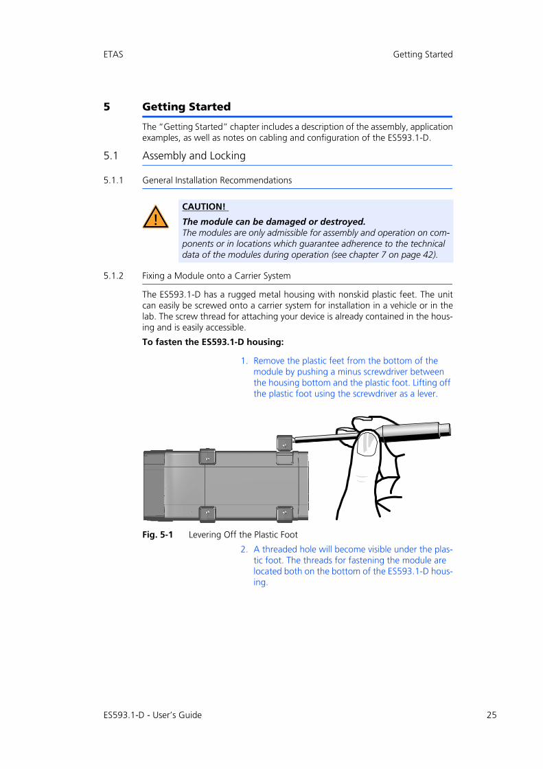
The ES593.1-D has a rugged metal housing with nonskid plastic feet. The unit can easily be screwed onto a carrier system for installation in a vehicle or in the lab. The screw thread for attaching your device is already contained in the hous-ing and is easily accessible.
To fasten the ES593.1-D housing:
1. Remove the plastic feet from the bottom of the module by pushing a minus screwdriver between the housing bottom and the plastic foot. Lifting off the plastic foot using the screwdriver as a lever.
Fig. 5-1 Levering Off the Plastic Foot
2. A threaded hole will become visible under the plas-tic foot. The threads for fastening the module are located both on the bottom of the ES593.1-D hous-ing.
CAUTION!
The module can be damaged or destroyed.The modules are only admissible for assembly and operation on com-ponents or in locations which guarantee adherence to the technical data of the modules during operation (see chapter 7 on page 42).
ES593.1-D - User’s Guide 25

26
Getting Started ETAS
Fig. 5-2 Tapped blind hole
5.1.3 Connecting Several Modules Mechanically
As ETAS system housing was used, the ES593.1-D can also be connected to mod-ules of the ETAS compact line (ES59x, ES6xx, ES910). These can be combined easily using the T-Brackets provided to form larger blocks.
You can attach a further module of the ETAS compact line under the ES593.1-D. Just remove the four plastic feet on each of the relevant device sides and attach the T-Brackets provided in their place.
To connect modules mechanically:
1. Remove the four plastic feet from the bottom of the ES593.1-D so a further module can be attached.
This makes the assembly slits for the T Brackets accessible.
You can attach a further module under the ES593.1-D.
2. Remove the four plastic feet on the relevant side of the second module.
3. Turn the seals of the T-Brackets so they are at a right angle to the longitudinal axis of the brackets and click two brackets into the assembly slits on one long side of the first module.
4. Click the second module into the two T-Brackets.
CAUTION!
The electronic can be damaged or destroyed!Do not rework the threaded hole.
Note
Use excluding M3 cylinder screws and fastening the module onto your carrier system with a max. torque of 0.8 Nm. The max. length of engagement into the tapped blind hole of housing is 3 mm (see Fig. 5-2 on page 26).
jP
MKOR=ñ=QRø
PKR=ãáå
QKR=ã~ñ
ES593.1-D - User’s Guide

ETAS Getting Started
Fig. 5-3 Connecting the ES593.1-D to Another Module
5. Quarter-turn the seals of the T-Brackets. This locks the connection of the two modules.
6. Click the other two T-Brackets into the assembly slits on the opposite long side of the device and lock these brackets too.
7. If you would like to stack further modules, repeat this procedure with the next module.
ES593.1-D - User’s Guide 27

28
Getting Started ETAS
5.2 Applications
For applications, the ES593.1-Dhas direct access to XETK ECUs and to ECUs and vehicle buses.
Fig. 5-4 ES593.1-D and ES595.1 with ES400 modules, XETK, ETK and vehicle buses
Note
You can find a list of applications supported by the ES593.1-D in chapter 7.7.2 on page 46.
Cable in Fig. 5-4
Function Short Name
1 Power supply cable CBP120, CBP1205
2 Host connecting cable CBE100
3 PC connecting and Power supply cable ES4xx, ES63x CBEP420, CBEP425
4 Ethernet connecting cable CBE130, CBE140
5 XETK connecting cable with XETK interface cable CBAE330 and CBE230
6 ETK connecting cable CBM150
7 CAN/ LIN/ FlexRay connecting cable CBCFI100
LIN
CAN
Ethernet
Application
4
7
CAN2 LIN2
7
CAN1 LIN1
ETK
6
ETK
ES595
1
7 ... 29 V DC
7
FLX1 FLX2
FlexRay Channel A
FlexRay Channel B
3
XCP on Ethernet
ES400
ES593-D
1
7 ... 29 V DC
5
XETK
XCP on Ethernet
Ethernet
ETH
2
ES593.1-D - User’s Guide

ETAS Getting Started
5.3 Wiring
The ports of the ES593.1-D may be wired in any order.
For order information on other cables which can be supplied separately, refer to the chapter "Cable and Accessories" on page 53.
5.3.1 “HOST” Port
To connect the ES593.1-D module with the PC (“HOST” port), you require the CBE100 cable provided.
To connect the ES593.1-D with the PC
1. Connect the HOST port of the ES593.1-D with the PC interface cable CBE100.
2. Connect the cable’s RJ-45 connector with the free Ethernet interface of your PC.
5.3.2 “7-29V” Port
To connect the ES593.1-D module with the power supply, you require the CBP120 cable or the CBP1205 cable provided.
To connect the ES593.1-D with the power supply
1. Connect the cable CBP120 or the cable CBP1205 for the power supply with the 7-29V port of the ES593.1-D.
2. Connect the supply voltage pins of the cable with the required power supply.
Note the color coding of the connectors.
Note the current consumption of the ES593.1-D and its supply voltage range. The admissible values are listed in section 7.8.1 on page 47.
Note
Be sure to check that the ports carry no voltage, before starting the cabling.
Note
Make sure you carefully check the names of the cables used. Using the wrong cables can keep your ES593.1-D from functioning properly or damage theES593.1-D and any devices connected to it.
DANGER!
Dangerous electrical voltage!Connect the power cable only with a suitable vehicle battery or with a suitable lab power supply! The connection to power outlets is not allowed!To prevent an inadvertent insertion in power outlets, ETAS recom-mends to equip the power cables with safety banana plugs CBP1205 in areas with power outlets.
ES593.1-D - User’s Guide 29
30
Getting Started ETAS
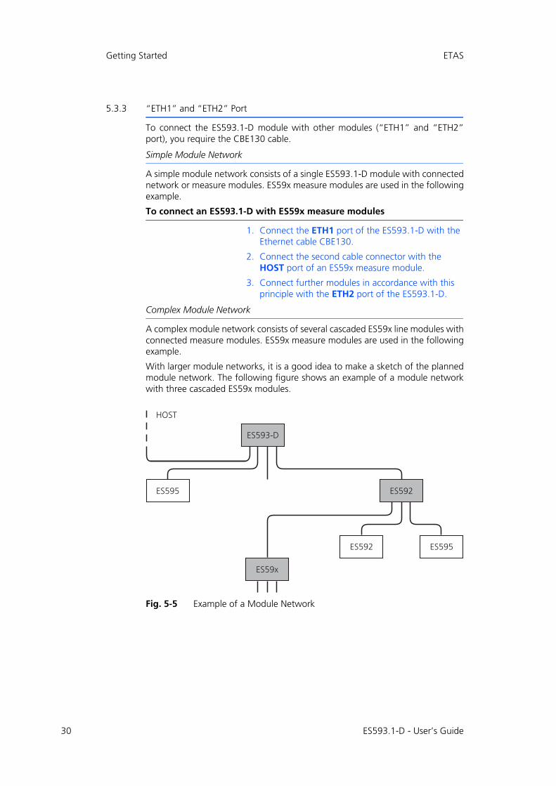
5.3.3 “ETH1” and “ETH2” Port
To connect the ES593.1-D module with other modules (“ETH1” and “ETH2” port), you require the CBE130 cable.
Simple Module Network
A simple module network consists of a single ES593.1-D module with connected network or measure modules. ES59x measure modules are used in the following example.
To connect an ES593.1-D with ES59x measure modules
1. Connect the ETH1 port of the ES593.1-D with the Ethernet cable CBE130.
2. Connect the second cable connector with the HOST port of an ES59x measure module.
3. Connect further modules in accordance with this principle with the ETH2 port of the ES593.1-D.
Complex Module Network
A complex module network consists of several cascaded ES59x line modules with connected measure modules. ES59x measure modules are used in the following example.
With larger module networks, it is a good idea to make a sketch of the planned module network. The following figure shows an example of a module network with three cascaded ES59x modules.
Fig. 5-5 Example of a Module Network
ES593-D
ES592ES595
ES592 ES595
ES59x
HOST
ES593.1-D - User’s Guide
ETAS Getting Started
To connect an ES59x module with other ES59x modules
1. Connect the HOST port of the subordinate ES59x module with the ETH1 port or with the ETH2 port of the superordinate ES593.1-D module
or
connect the HOST port of the subordinate ES59x module with the ETH1 port of the superordinate ES595.1 module
The superordinate ES59x module is nearer the host PC in the hierarchy.
2. Connect further ES59x modules in accordance with this principle with other ETH ports of the ES59x module.
ES593.1-D - User’s Guide 31
32
Getting Started ETAS
5.4 Configuring the ES593.1-D
The ES593.1-D is configured at the PC via a graphic user interface. A web browser application is used as an interface.
5.4.1 Web Interface
The web interface of the ES593.1-D consists of a home page, a page for custom-ized configuration of the interfaces for the "Wake Up" function and other pages with information on the status of the ES593.1-D.
5.4.2 Launching the ES593.1-D Web Interface
To launch the ES593.1-D web interface:
1. Connect the ES593.1-D to the PC.
2. Start the HSP program on the PC.
3. Click Hardware Search.
4. Highlight the ES593.1-D configured in the Hard-ware window.
5. Right-click System Configuration.
The default web browser launches the web inter-face for configuring the ES593.1-D with the current IP address of the module in the address field.
The home page of the ES593.1-D web interface is displayed.
5.4.3 Configuring the “Wake Up” Function
To configure the “Wake Up” function:
1. Click Device Configuration.
2. Click Wake Up.
The page for configuring the “Wake Up” function is displayed.
3. Configure the interfaces of the ES593.1-D for the Wake Up function.
ES593.1-D - User’s Guide

ETAS Troubleshooting Problems
6 Troubleshooting Problems
This chapter gives some information of what you can do when problems arise with the ES593.1-D and problems that are not specific to an individual software or hardware product.
6.1 Error LEDs
Please observe the LED which provides information on the functions of the inter-face and the ES593.1-D (see the chapter "LEDs" on page 15) to be able to judge the operational state of the ES593.1-D as well as troubleshooting measures.
6.2 Troubleshooting ES593.1-D Problems
The following table lists some of the possible problems with a remedy.
If you have any further questions, please contact our Customer Support (see chapter 10 on page 71).
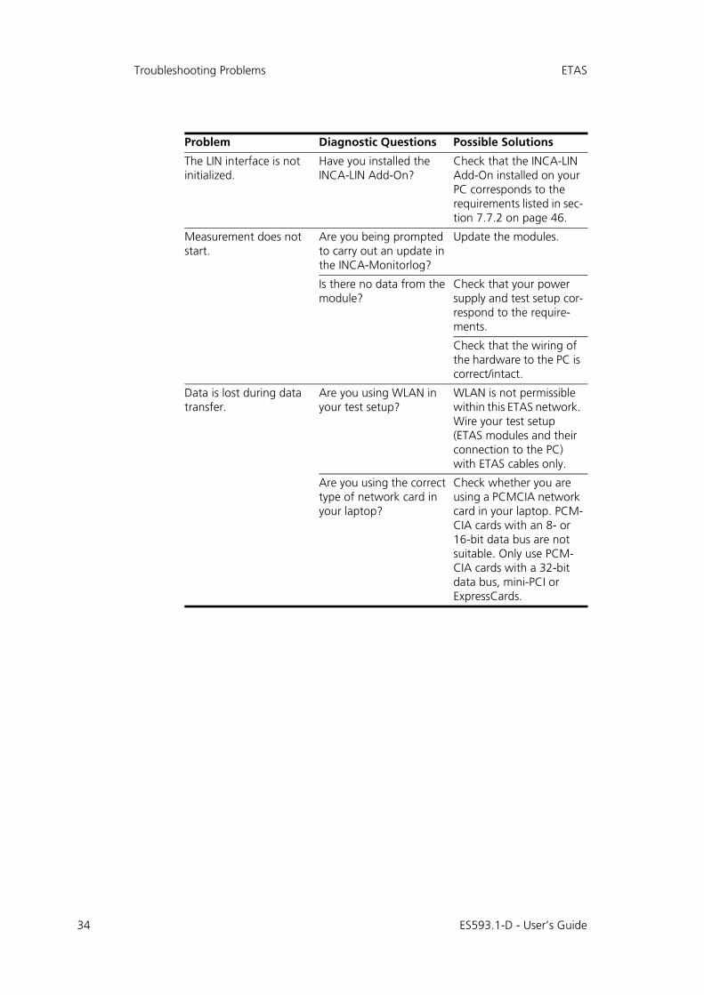
Problem Diagnostic Questions Possible Solutions
The ES593.1-D is not found with "Search for Hardware" in INCA.
Did you install the INCA version required?
Check that the INCA soft-ware installed on your PC corresponds to the requirements listed in sec-tion 7.7.2 on page 46.
Did you install the INCA ES5xx Add-On version required?
Check that the INCA ES5xx Add-On installed on your PC corresponds to the requirements listed in section 7.7.2 on page 46.
Did you configure the network card correctly?
INCA, Config Tool and HSP operation:Check that your network card has been configured in accordance with sec-tion 7.7.1 on page 45.
Is the hardware on the PC connected?
Check that the connec-tion is undamaged.
The ETK interface is not initialized.
Have you installed the ETK Drivers and Tools?
Check that ETK Drivers and Tools installed on your PC corresponds to the requirements listed in section 7.7.2 on page 46.
Which ETK is connected? Check whether the con-nected ETK is supported (see chapter 7.8.4 on page 49).
ES593.1-D - User’s Guide 33
34
Troubleshooting Problems ETAS
The LIN interface is not initialized.
Have you installed the INCA-LIN Add-On?
Check that the INCA-LIN Add-On installed on your PC corresponds to the requirements listed in sec-tion 7.7.2 on page 46.
Measurement does not start.
Are you being prompted to carry out an update in the INCA-Monitorlog?
Update the modules.
Is there no data from the module?
Check that your power supply and test setup cor-respond to the require-ments.
Check that the wiring of the hardware to the PC is correct/intact.
Data is lost during data transfer.
Are you using WLAN in your test setup?
WLAN is not permissible within this ETAS network. Wire your test setup (ETAS modules and their connection to the PC) with ETAS cables only.
Are you using the correct type of network card in your laptop?
Check whether you are using a PCMCIA network card in your laptop. PCM-CIA cards with an 8- or 16-bit data bus are not suitable. Only use PCM-CIA cards with a 32-bit data bus, mini-PCI or ExpressCards.
Problem Diagnostic Questions Possible Solutions
ES593.1-D - User’s Guide
ETAS Troubleshooting Problems
6.3 Problems and Solutions
This chapter contains information on general problems and their solutions for those using the ES400 modules with INCA or with the ES4xx Configuration Tool.
6.3.1 Network Adapter cannot be selected via Network Manager
Cause: APIPA is disabled
The alternative mechanism for IP addressing (APIPA) is usually enabled on all Windows XP and Vista systems. Network security policies, however, may request the APIPA mechanism to be disabled. In this case, you cannot use a network adapter which is configured for DHCP to access ETAS hardware. The ETAS Net-work Manager displays a warning message.
The APIPA mechanism can be enabled by editing the Windows registry. This is permitted only to users who have administrator privileges. It should be done only in coordination with your network administrator.
To enable the APIPA mechanism:
1. Open the Registry Editor:
– Windows XP:1.1 Click Start.1.2 Click Run. 1.3 Enter regedit.1.4 Click OK.
– Windows Vista:1.1 Click Start.1.2 Enter regedit in the entry field.1.3 Push <ENTER>.
The registry editor is displayed.
2. Open the folder HKEY_LOCAL_MACHINE\SYS-TEM\CurrentControlSet\Services\Tcpic\Parameters\
3. Click Edit Find to search for the key IPAuto-configurationEnabled.
If you cannot find any instances of the registry key mentioned, the APIPA mech-anism has not been disabled on your system, i.e. there is no need to enable it. Otherwise proceed with the following steps.
4. Set the value of the key IPAutoconfiguratio-nEnabled to 1 to enable the APIPA mechanism.
You may find several instances of this key in the Windows registry which either apply to the TCP/IP service in general or to a specific network adapter. You only need to change the value for the corre-sponding network adapter.
5. Close the registry editor.
6. Restart your workstation in order to make your changes take effect.
ES593.1-D - User’s Guide 35

36
Troubleshooting Problems ETAS
6.3.2 Search for Ethernet Hardware Fails
Cause: Personal Firewall blocks Communication
For a detailed description on problems caused by personal firewalls and possible solutions see "Personal Firewall Blocks Communication" on page 37.
Cause: Client Software for Remote Access blocks Communication
PCs or notebooks which are used outside the ETAS hardware network sometimes use a client software for remote access which might block communication to the ETAS hardware. This can have the following causes:
• A firewall which is blocking Ethernet messages is being used (see „Cause: Personal Firewall blocks Communication“ on page36)
• By mistake, the VPN client software used for tunneling filters messages. As an example, Cisco VPN clients with versions before V4.0.x in some cases erroneously filtered certain UDP broadcasts.
If this might be the case, please update the software of your VPN client.
Cause: ETAS Hardware hangs
Occasionally the ETAS hardware might hang. In this case switch the hardware off, then switch it on again to re-initialize it.
Cause: Network Adapter temporarily has no IP Address
Whenever you switch from a DHCP company LAN to the ETAS hardware net-work, it takes at least 60 seconds until ETAS hardware can be found. This is caused by the operating system’s switching from the DHCP protocol to APIPA, which is being used by the ETAS hardware.
Cause: ETAS Hardware had been connected to another Logical Network
If you use more than one PC or notebook for accessing the same ETAS hardware, the network adapters used must be configured to use the same logical network. If this is not possible, it is necessary to switch the ETAS hardware off and on again between different sessions (repowering).
Cause: Device driver for network card not in operation
It is possible that the device driver of a network card is not running. In this case you will have to deactivate and then reactivate the network card.
To deactivate and reactivate the network card:
1. To deactivate the network card first select in the Windows start menu the following item:
– Windows XP: Control Panel Network Connections
– Windows Vista:Control Panel Network and Internet Network and Sharing Center Manage Network Connections
2. Right click on the used network adapter.
3. Select Disable in the context menu.
ES593.1-D - User’s Guide
ETAS Troubleshooting Problems
4. In order to reactivate the network adapter right click on it again.
5. Select Enable.
Cause: Laptop power management deactivates the network card
The power management of a laptop computer can deactivate the network card. Therefore you should turn off power monitoring on the laptop.
To switch off power monitoring on the laptop:
1. From the Windows Start Menu, select
– Windows XP: Control Panel System. Then select the Hardware tab.Click on Device Manager.
– Windows Vista:Control Panel System and MaintenanceDevice Manager.
2. In the Device Manager open the tree structure of the entry Network Adapters.
3. Right click on the used network adapter.
4. Select Properties in the context menu.
5. Select the Power Management tab.
6. Deactivate the Allow the computer to turn off this device to save power option.
7. Select the Advanced tab.
8. If the property Autosense is included, deactivate it.
9. Click OK to apply the settings.
Cause: Automatic disruption of network connection
It is possible after a certain period of time without data traffic that the network card automatically interrupts the Ethernet connection. This can be prevented by setting the registry key autodisconnect.
To set the registry key autodisconnect:
1. Open the Registry Editor.
2. Select under HKEY_LOCAL_MACHINE\SYSTEM\ControlSet001\Services\lanmanserver\parameters the Registry Key autodisconnect and change its value to 0xffffffff.
6.3.3 Personal Firewall Blocks Communication
Cause: Permissions given through the firewall block ETAS hardware
Personal firewalls may interfere with access to ETAS Ethernet hardware. The automatic search for hardware typically cannot find any Ethernet hardware at all, although the configuration parameters are correct.
ES593.1-D - User’s Guide 37

38
Troubleshooting Problems ETAS
Certain actions in ETAS products may lead to some trouble if the firewall is not properly parameterized, e.g. upon opening an experiment in ASCET or searching for hardware from within INCA or HSP.
If a firewall is blocking communication to ETAS hardware, you must either disable the firewall software while working with ETAS software, or the firewall must be configured to give the following permissions:
• Outgoing limited IP broadcasts via UDP (destination address 255.255.255.255) for destination port 18001
• Incoming limited IP broadcasts via UDP (destination IP 255.255.255.255, originating from source IP 0.0.0.0) for destination port 18001
• Directed IP broadcasts via UDP to the network configured for the ETAS application, destination port 18001
• Outgoing IP unicasts via UDP to any IP in network configured for the ETAS application, destination ports 69, 18001, 18017 or 49152 to 50175
• Incoming IP unicasts via UDP originating from any IP in the network con-figured for the ETAS application, source ports 69, 18001, 18017 or 49152 to 50175
Windows XP and Vista come with a built-in personal firewall. On many other systems it is very common to have personal firewall software from third party vendors, such as Symantec, McAffee or BlackIce installed. The proceedings in configuring the ports might differ for each personal firewall software used. Therefore please refer to the user documentation of your personal firewall soft-ware for further details.
As an example for a firewall configuration, you will find below a description on how to configure the widely used Windows XP firewall if the hardware access is prohibited under Windows XP with Service Pack 2.
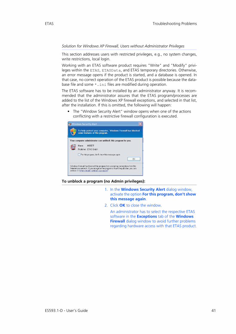
Solution for Windows XP Firewall, Users with Administrator Privileges
If you have administrator privileges on your PC, the following dialog window opens if the firewall blocks an ETAS product.
Note
The ports that have to be used in concrete use cases depend on the hard-ware used. For more precise information on the port numbers that can be used please refer to your hardware documentation.
ES593.1-D - User’s Guide

ETAS Troubleshooting Problems
To unblock a product:
1. In the Windows Security Alert dialog window, click on Unblock.
The firewall no longer blocks the ETAS product in question (in the example: ASCET). This decision sur-vives a restart of the program, or even the PC.
Instead of waiting for the "Windows Security Alert" dialog window, you can unblock ETAS products in advance.
To unblock ETAS products in the firewall control:
1. From the Windows Start Menu, select Settings Control Panel.
2. In the control panel, double-click the Windows Firewall icon.
ES593.1-D - User’s Guide 39

40
Troubleshooting Problems ETAS
3. In the Windows Firewall dialog window, open the Exceptions tab.
This tab lists the exceptions not blocked by the fire-wall. Use Add Program or Edit to add new pro-grams, or edit existing ones.
4. Make sure that the ETAS products and services you want to use are properly configured exceptions.
4.1 Open the Change Setup window.
4.2 To ensure proper ETAS hardware access, make sure that at least the IP addresses 192.168.40.xxx are unblocked.
4.3 Close the Change Setup window with OK.
5. Close the Windows Firewall dialog window with OK.
The firewall no longer blocks the ETAS product in question. This decision survives a restart of the PC.
ES593.1-D - User’s Guide
ETAS Troubleshooting Problems
Solution for Windows XP Firewall, Users without Administrator Privileges
This section addresses users with restricted privileges, e.g., no system changes, write restrictions, local login.
Working with an ETAS software product requires "Write" and "Modify" privi-leges within the ETAS, ETASData, and ETAS temporary directories. Otherwise, an error message opens if the product is started, and a database is opened. In that case, no correct operation of the ETAS product is possible because the data-base file and some *.ini files are modified during operation.
The ETAS software has to be installed by an administrator anyway. It is recom-mended that the administrator assures that the ETAS program/processes are added to the list of the Windows XP firewall exceptions, and selected in that list, after the installation. If this is omitted, the following will happen:
• The "Window Security Alert" window opens when one of the actions conflicting with a restrictive firewall configuration is executed.
To unblock a program (no Admin privileges):
1. In the Windows Security Alert dialog window, activate the option For this program, don’t show this message again.
2. Click OK to close the window.
An administrator has to select the respective ETAS software in the Exceptions tab of the Windows Firewall dialog window to avoid further problems regarding hardware access with that ETAS product.
ES593.1-D - User’s Guide 41

42
Technical Data ETAS
7 Technical Data
This chapter contains information on the following topics:
• "General Data" on page 42
• "RoHS Conformity" on page 44
• "CE Labeling" on page 44
• "Taking the Product Back and Recycling" on page 44
• "Declarable Substances" on page 45
• "Use of Open Source Software" on page 45
• "System Requirements" on page 45
• "Electrical Data" on page 47
• "Pin Assignment" on page 50.
7.1 General Data
7.1.1 Product Labeling
The following symbols are used for product labeling:
Symbol Description
Prior to operating the product, be sure to read the user’s guide!
SN: 1234567 Serial number (seven-digit)
Vx.y.z Hardware version of the product
F 00K 123 456 Ordering number of the product, see chapter 9.1 on page 67
Operating voltage range (DC)
xy A Current consumption, max.
Labeling for CE conformity, see chapter 7.3 on page 44
Labeling for WEEE, see chapter 7.4 on page 44
Labeling for RoHS (China), see chapter 7.2.2 on page 44
29V7
ES593.1-D - User’s Guide

ETAS Technical Data
7.1.2 Fulfilled Standards and Norms
The module adheres to the following standards and norms:
7.1.3 Environmental Conditions
7.1.4 Maintenance the Product
Do not open or change the module! Works on the module housing may be exe-cuted only by qualified technical personnel. Send defect modules to ETAS.
7.1.5 Cleaning the Product
We recommend to clean the product with a dry cloth.
Norm Test
EN 61326-1 Electrical equipment for measurement, control and laboratory use - EMC requirements
EN 61000-6-2 Immunity for industrial environments
EN 61000-6-3 Emission standard (residential, com-mercial and light-industrial environ-ments)
EN 60 529 Degrees of protection provided by enclosures (IP code)
EN 60 068-2-32 Basic environmental testing proce-dures; part 2: tests; test Ed: free fall
Temperature range (operation) -40 °C bis +70 °C
-40 °F bis +158 °F
Temperature range (storage)(module without packaging)
-40 °C bis +85 °C
-40 °F bis +185 °F
Relative humidity (non-condensing) 0 to 85% (operation)
0 to 95% (storage)
Implementation altitude max. 5000 m/ 16400 ft
Protection class IP30
Degree of pollution 2
Note
The module is suited for use in interiors, in the passenger compartment or in the luggage compartment of vehicles. The module is not suited for installation in the engine compartment and similar environments.
ES593.1-D - User’s Guide 43

44
Technical Data ETAS
7.1.6 Mechanical Data
7.2 RoHS Conformity
7.2.1 European Union
The EU Directive 2002/95/EU limits the use of certain dangerous materials for electrical and electronic devices (RoHS conformity).
ETAS confirms that the product corresponds to this directive which is applicable in the European Union.
7.2.2 China
ETAS confirms that the product meets the product-specific applicable guidelines of the China RoHS (Management Methods for Controlling Pollution Caused by Electronic Information Products Regulation) applicable in China with the China RoHS marking affixed to the product or its packaging.
7.3 CE Labeling
ETAS confirms that the product meets the product-specific, applicable European guideline with a CE label on the product or its packaging. CE conformity decla-ration for the product is available upon request.
7.4 Taking the Product Back and Recycling
The European Union has passed a directive called Waste Electrical and Electronic Equipment, or WEEE for short, to ensure that systems are setup throughout the EU for the collection, treating and recycling of electronic waste.
This ensures that the devices are recycled in a resource-saving way representing no danger to health or the environment.
Fig. 7-1 WEEE Symbol
The WEEE symbol (see Fig. 7-1 on page 44) on the product or its packaging shows that the product must not be disposed of as residual garbage.
The user is obliged to collect the old devices separately and return them to the WEEE take-back system for recycling.
The WEEE directive concerns all ETAS devices but not external cables or batteries.
For more information on the ETAS GmbH Recycling Program, contact the ETAS sales and service locations (see chapter 10 on page 71).
Dimensions (H x W x D) 45 mm x 127 mm x 160 mm
1.75 in x 5.0 in x 6.3 in
Weight Approx. 0.8 kg/ 1.8 lbs
ES593.1-D - User’s Guide
ETAS Technical Data
7.5 Declarable Substances
European Union
Some products from ETAS GmbH (e.g. modules, boards, cables) use components with substances that are subject to declaration in accordance with the REACH regulation (EU) no.1907/2006. Detailed information is located in the ETAS download center in the customer information "REACH Declaration" (www.etas.com/Reach). This information is continuously being updated.
7.6 Use of Open Source Software
The product uses Open Source Software (OSS). This software is installed in the product at the time of delivery and does not have to be installed or updated by the user. Reference shall be made to the use of the software in order to fulfill OSS licensing terms. Additional information is available in the document "OSS Attri-butions List" at the ETAS website www.etas.com.
7.7 System Requirements
7.7.1 Hardware
Operation of the ES593.1-D requires a power supply voltage of 7 V to 29 V DC.
PC with one Ethernet interface
A PC with one open Ethernet interface (100 Mbit/s, full duplex) with RJ-45 con-nection is required. Ethernet interfaces that are implemented with an additional network card in the PC must feature a 32-bit data bus.
Requirement to ensure successful initialization of the module
To deactivate the power saving mode:
Choose in System Control Center / Device Manager / Network Adapter the used network adapter by double-click. Deactivate the "Allow the computer to turn off this device to save power" option in the "Power Management" register. Confirm your configuration.
The manufacturers of network adapter have different names for this function.
Example:
• “Link down Power saving”
• "Allow the computer to turn off this device to save power".
Note
It is imperative you disable the function which automatically switches to power-saving mode on your PC network adapter when there is no data traffic on the Ethernet interface!
ES593.1-D - User’s Guide 45

46
Technical Data ETAS
7.7.2 Supported Applications and Software Requirements
To configure the ES593.1-D and for control and data acquisition, you need soft-ware in the following versions:
Support in Application Software
Inter-face
Application Classifi-cation 1)
INCA V6.2.1 2) INCA V7.0 3)
ETH XCP on Ethernet MC yes yes
ETK ETKMeasurement and Calibration
MC yes 4) yes 5)
CAN CAN Monitoring MC yes yes
CAN Output MC yes yes
CCP MC yes yes
KWP on CAN MC yes yes
UDS MC yes yes
XCP on CAN MC yes yes
Pre-Buffering MC no yes 6)
Wake-Up MC no yes 6)
1): MC: Measurement and Calibration2): INCA V6.2.1 with Hotfix 13 and higher and additionally INCA-ES5xx Add-On V6.2.2 and higher3): additionally INCA-ES5xx Add-On V7.0.0 and higher3): additionally ETK Drivers and Tools V2.1.6 and higher3): additionally ETK Drivers and Tools V3.0.0 and higher3): only for interfaces CAN1 and CAN2
ES593.1-D - User’s Guide
ETAS Technical Data
7.8 Electrical Data
7.8.1 Power Supply
7.8.2 Host Interface (HOST)
Operating voltage 7 V to 29 V DC
Power consumption, normal mode 1) Typ. 500 mA at 14,4 V DC
Power consumption, standby 1) Typ. 20 mA at 14,4 V DC
Current consumption, total Max. 7 A(module: max. 3 A, output current per connection "ETH": nom. max. 2 A)
Energy management On/ off at start/ stop of the Ethernet com-munication (on/ off upstream module)
Protection 2) Protected against polarity inversion and Load Dump protection
1): module without power supply of connected modules2): The module may be used only with central load dump protection.
Anschlusstyp Upstream
Anzahl 1 (HOST)
Verbindung 10/100Base-T Ethernet
Protocol TCP/IP
Protocol Ethernet Switching (Layer 2), IEEE802.3
Resolution synchronization 1 s
Compatibility 1) PC
ES720 Drive Recorder
Network and interface modules: ES51x, ES592, ES593-D, ES595, ES600
1): Support of the ETAS synchronization mechanism
Note
To ensure successful initialization of the network card of your PC, refer to chap-ter "Hardware" on page 45.
ES593.1-D - User’s Guide 47

48
Technical Data ETAS
7.8.3 Ethernet Interfaces (ETH1 and ETH2)
Type of connection Downstream
Number 2 (ETH1, ETH2)
Connection 10/100Base-T Ethernet
Protocol TCP/IP
Resolution synchronization 1 s
Nom. max. output current per con-nection "ETH"
Min. 2 A
Power supply of connected modules ES4xx Measurement Modules,ES6xx Measurement Modules, XETKs
Compatibility 1) Network Module: ES600
Network and interface modules: ES51x, ES592, ES593-D, ES595
Measurement modules:ES4xx, ES6xx, ES930.1
Prototyping and Interface Module:ES910.3
ECUs with XETK,ECUs with Ethernet interface
Third party Ethernet devices 2)
1): Support of ETAS synchronization mechanism2): No support of ETAS synchronization mechanism
ES593.1-D - User’s Guide
ETAS Technical Data
7.8.4 ETK Interface (ETK)
7.8.5 CAN Interfaces (CAN1/CAN3 and CAN2/CAN4)
CAN Interfaces (CAN1/CAN3 and CAN2/CAN4)
CAN Interfaces with "CAN Pre-Buffering" Function (CAN1/CAN2)
Operating modes Basic, Compatibility, Advanced
ETK protocol speed 8 Mbit/s / 100 Mbit/s
ETK protocol transfer Single Mode / Block Mode
Note
The ES593.1-D supports all current ETK types.Exception:The ETK types not supported by the module are listed in the table. For more details, refer to the ETAS website.
ETKs not supported ETKMETK3.xETK4ETK6.xETK7.0METK1METK2ETK8.0ETK8.1ETKS1.0-AETKS1.0-BETKP1.0
CAN1, CAN2, CAN3 and CAN4 4 independent interfaces,galvanically isolated from each other and from the other interfaces,every channel separately configurable (High-Speed CAN)
Protocols CAN V2.0a (Standard Identifier),CAN V2.0b (Extended Identifier)
Transceiver (Physical Layer) TJA1040
Transfer speed Max. 1 MBaud with a bus length of 20 m
Differential internal resistor Ri 10 kOhm
CAN Pre-Buffering Boot time to start of recording: 100 ms
Wake-Up System Wake-Up (CAN activity)
ES593.1-D - User’s Guide 49
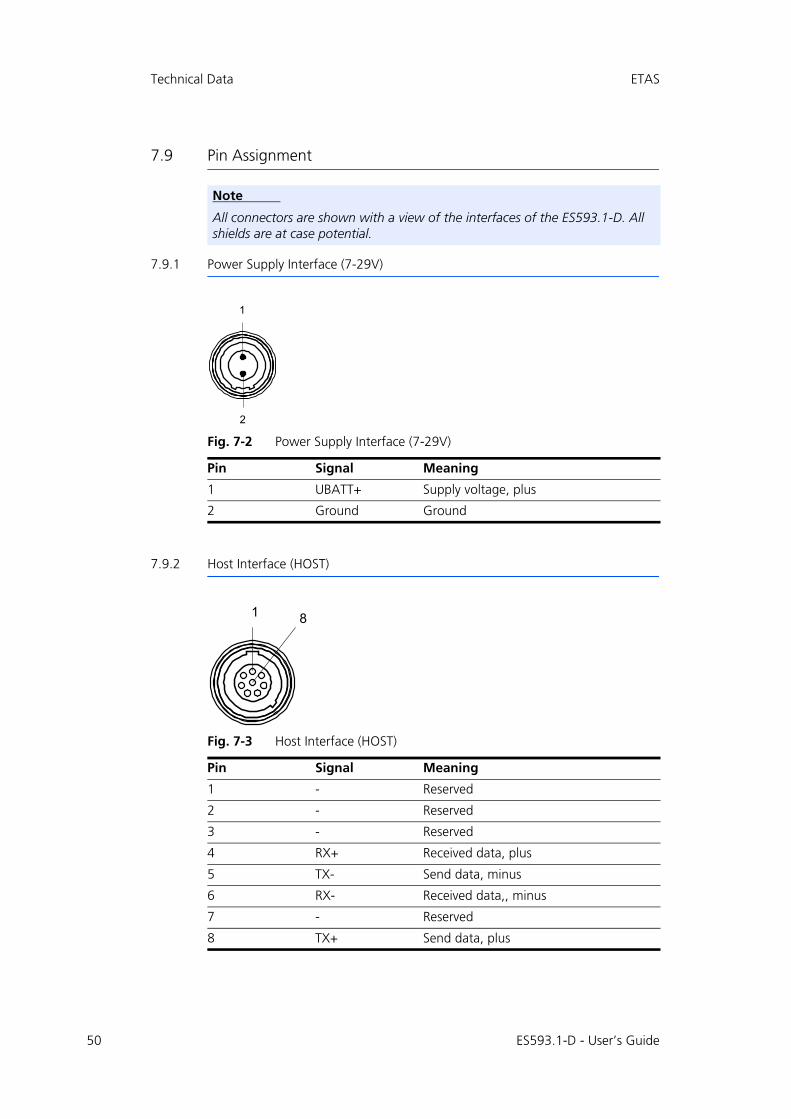
50
Technical Data ETAS
7.9 Pin Assignment
7.9.1 Power Supply Interface (7-29V)
Fig. 7-2 Power Supply Interface (7-29V)
7.9.2 Host Interface (HOST)
Fig. 7-3 Host Interface (HOST)
Note
All connectors are shown with a view of the interfaces of the ES593.1-D. All shields are at case potential.
Pin Signal Meaning
1 UBATT+ Supply voltage, plus
2 Ground Ground
Pin Signal Meaning
1 - Reserved
2 - Reserved
3 - Reserved
4 RX+ Received data, plus
5 TX- Send data, minus
6 RX- Received data,, minus
7 - Reserved
8 TX+ Send data, plus
2
1
1 8
ES593.1-D - User’s Guide
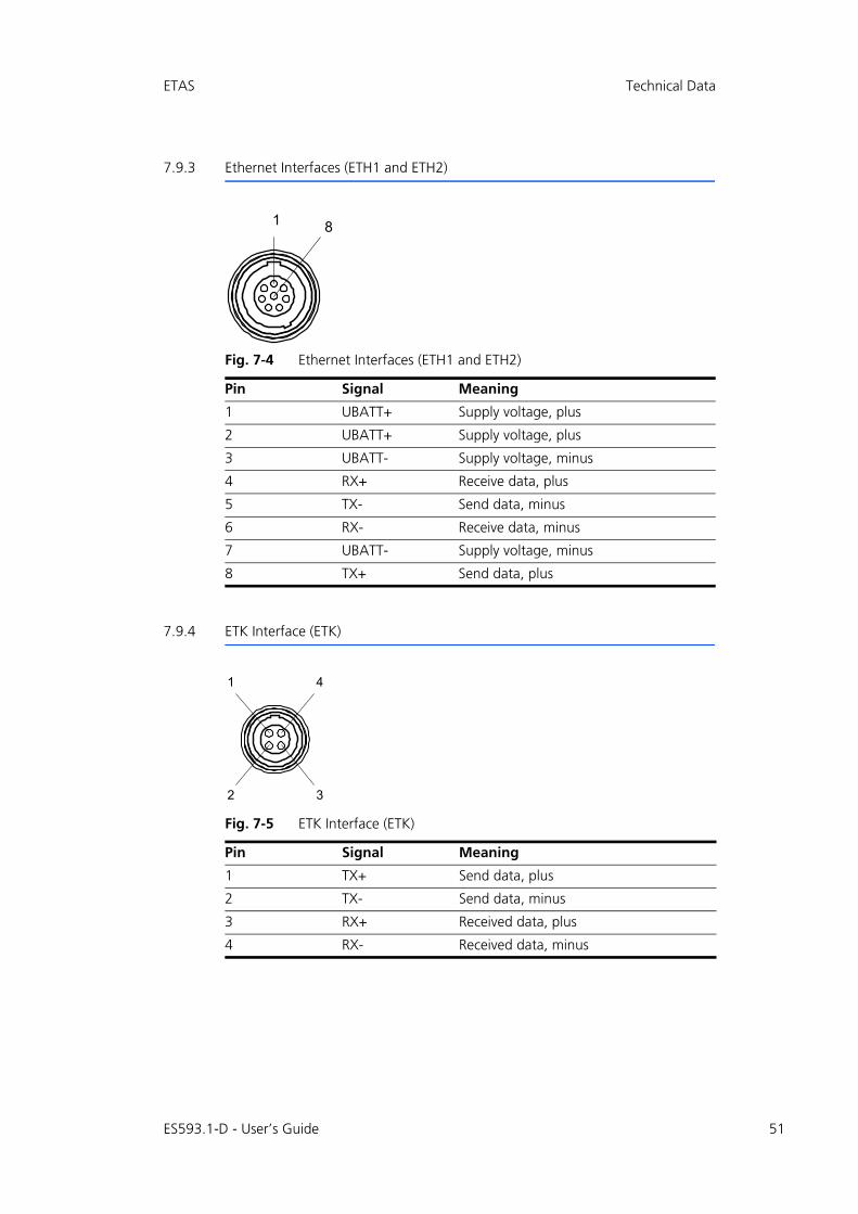
ETAS Technical Data
7.9.3 Ethernet Interfaces (ETH1 and ETH2)
Fig. 7-4 Ethernet Interfaces (ETH1 and ETH2)
7.9.4 ETK Interface (ETK)
Fig. 7-5 ETK Interface (ETK)
Pin Signal Meaning
1 UBATT+ Supply voltage, plus
2 UBATT+ Supply voltage, plus
3 UBATT- Supply voltage, minus
4 RX+ Receive data, plus
5 TX- Send data, minus
6 RX- Receive data, minus
7 UBATT- Supply voltage, minus
8 TX+ Send data, plus
Pin Signal Meaning
1 TX+ Send data, plus
2 TX- Send data, minus
3 RX+ Received data, plus
4 RX- Received data, minus
1 8
1
3
4
2
ES593.1-D - User’s Guide 51

52
Technical Data ETAS
7.9.5 CAN Interface (CAN1/CAN3)
Fig. 7-6 CAN Interface (CAN1 and CAN3)
7.9.6 CAN Interface (CAN2/CAN4)
Fig. 7-7 CAN Interface (CAN2 and CAN4)
Pin Signal Meaning
1 - Reserved
2 CAN1_LOW
3 CAN1_GND_1
4 CAN3_HIGH
5 CAN3_GND
6 CAN1_GND_2
7 CAN1_HIGH
8 CAN3_LOW
Pin Signal Meaning
1 - Reserved
2 CAN2_LOW
3 CAN2_GND_1
4 CAN4_HIGH
5 CAN4_GND
6 CAN2_GND_2
7 CAN2_HIGH
8 CAN4_LOW
1 8
1 8
ES593.1-D - User’s Guide
ETAS Cable and Accessories
8 Cable and Accessories
The “Cables and Accessories” chapter contains an overview of the available cables and accessories.
8.1 Cable for the "7-29 V DC" Connection
Power supply cables suitable for the ES593.1-D module can be delivered in two designs:
• power supply cable CBP120 with standard banana plugs (current design) and
• power supply cable CBP1205 with safety banana plugs (new design).
Note
Only use the ETAS cables named in this User’s Guide at the interfaces of the ES593.1-D. The maximum admissible cable lengths must be adhered to.
Note
Custom cables can be produced according to your specifications. For more information on custom cables, please contact your local ETAS sales representa-tive.
DANGER!
Dangerous electrical voltage!Connect the power cable only with a suitable vehicle battery or with a suitable lab power supply! The connection to power outlets is not allowed!To prevent an inadvertent insertion in power outlets, ETAS recom-mends to equip the power cables with safety banana plugs CBP1205 in areas with power outlets.
Note
Application, permissible voltages and all the other technical data of the power supply cables are identical for both designs.
ES593.1-D - User’s Guide 53

54
Cable and Accessories ETAS
8.1.1 CBP120 Cable
Fig. 8-1 Cable CBP120-2 (power supply cable with standard banana plugs)
Side A Side B
Side A Side B
Pin Signal Plug Signal
1 UBATT- Red UBATT-
2 Ground Black Ground
Order name Short name Ordernumber
Power Supply Cable, Lemo 1B FGJ Banana (2fc-2mc), 2 m
CBP120-2 F 00K 102 584
ES593.1-D - User’s Guide

ETAS Cable and Accessories
8.1.2 CBP1205 Cable
Fig. 8-2 Cable CBP1205 (power supply cable with safety banana plugs)
Side A Side B
Side A Side B
Pin Signal Plug Signal
1 UBATT Red UBATT
2 Ground Black Ground
Order Name Short name Order Number
Power Supply Cable, Lemo 1B FGJ – Safety Banana (2fc-2mc), 2 m
CBP1205-2 F 00K 110 023
Note
Power supply cables with safety banana plug are suitable only for connection to voltage sources with safety socket.
ES593.1-D - User’s Guide 55

56
Cable and Accessories ETAS
8.2 HOST Interface Cable
Fig. 8-3 CBE100-x Cable
8.3 ETH1 und ETH2 Interface Cable
8.3.1 Ethernet Connection and Power Supply Cable
CBE130-x Cable
Fig. 8-4 CBE130-x Cable
Side A Side B
Order Name Short name Order Number
Ethernet PC Connection Cable, Lemo 1B FGG - RJ45 (8mc-8mc), 3 m
CBE100-3 F 00K 102 559
Ethernet PC Connection Cable, Lemo 1B FGG - RJ45 (8mc-8mc), 8 m
CBE100-8 F 00K 102 571
Side A Side B
Order Name Short name Order Number
Ethernet Connection and Power Supply Cable, Lemo 1B FGF Lemo 1B FGD (8mc-8mc), 0m45
CBE130-0m45 F 00K 102 748
Ethernet Connection and Power Supply Cable, Lemo 1B FGF Lemo 1B FGD (8mc-8mc), 3 m
CBE130-3 F 00K 102 587
ES593.1-D - User’s Guide
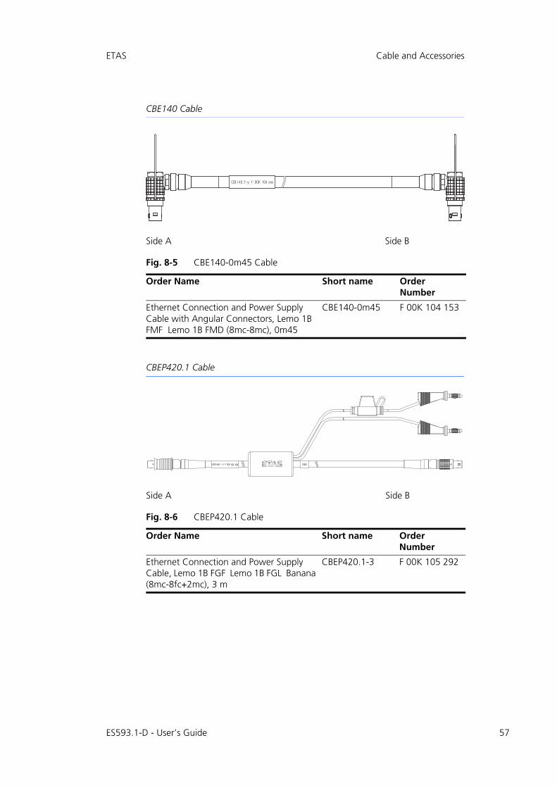
ETAS Cable and Accessories
CBE140 Cable
Fig. 8-5 CBE140-0m45 Cable
CBEP420.1 Cable
Fig. 8-6 CBEP420.1 Cable
Side A Side B
Order Name Short name Order Number
Ethernet Connection and Power Supply Cable with Angular Connectors, Lemo 1B FMF Lemo 1B FMD (8mc-8mc), 0m45
CBE140-0m45 F 00K 104 153
Side A Side B
Order Name Short name Order Number
Ethernet Connection and Power Supply Cable, Lemo 1B FGF Lemo 1B FGL Banana (8mc-8fc+2mc), 3 m
CBEP420.1-3 F 00K 105 292
ES593.1-D - User’s Guide 57

58
Cable and Accessories ETAS
CBEP425.1 Cable
Fig. 8-7 CBEP425.1 Cable
8.3.2 Ethernet Connection Cable
CBE400.2 Cable
Fig. 8-8 CBE400.2 Cable
Side A Side B
Order Name Short name Order Number
Ethernet Connection and Power Supply Cable, Lemo 1B FGF Lemo 1B FGL Banana (8mc-8fc+2mc), 3 m
CBEP425.1-3 F 00K 105 972
Note
The wiring of the modules of the ES400 product family with each other and the cables required by the modules are described in the documentation of the ES4xx modules.
Side A Side B
Order Name Short name Order Number
Ethernet PC Connection Cable, Lemo 1B FGF Lemo 1B FGL (8mc-8fc), 3 m
CBE400.2-3 F00K 104 920
ES593.1-D - User’s Guide

ETAS Cable and Accessories
CBE401.1 Cable
Fig. 8-9 CBE401.1 Cable
8.3.3 Ethernet Connection Adapter Cable
Fig. 8-10 CBAE330.2 Cable
Side A Side B
Order Name Short name Order Number
Ethernet PC Connection Cable, Highly Flex-ible, Lemo 1B FGF Lemo 1B FGL (8mc-8fc), 0m5
CBE401.1-0m5 F00K 106 128
Side A Side B
Order Name Short name Order Number
Ethernet Connection Adapter Cable 1 Gbit/s to 100 Mbit/s, Lemo 1B PHE - Lemo 1B FGF (10fc-8mc), 0m5
CBAE330-0m5 F 00K 105 759
ES593.1-D - User’s Guide 59
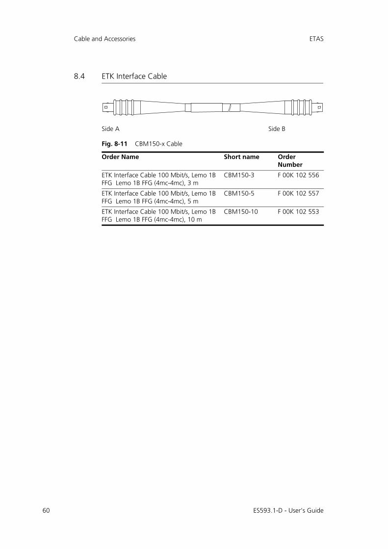
60
Cable and Accessories ETAS
8.4 ETK Interface Cable
Fig. 8-11 CBM150-x Cable
Side A Side B
Order Name Short name Order Number
ETK Interface Cable 100 Mbit/s, Lemo 1B FFG Lemo 1B FFG (4mc-4mc), 3 m
CBM150-3 F 00K 102 556
ETK Interface Cable 100 Mbit/s, Lemo 1B FFG Lemo 1B FFG (4mc-4mc), 5 m
CBM150-5 F 00K 102 557
ETK Interface Cable 100 Mbit/s, Lemo 1B FFG Lemo 1B FFG (4mc-4mc), 10 m
CBM150-10 F 00K 102 553
ES593.1-D - User’s Guide

ETAS Cable and Accessories
8.5 CAN/LIN Interface Cable and Adapter
8.5.1 CAN Interface Cable
CBAC150-2m5 Cable
Fig. 8-12 CBAC150-2m5 Cable
CBAC160-1m5 Cable
Fig. 8-13 CBAC160-1m5 Cable
Side A Side B
Order Name Short name Order Number
CAN Interface Cable, OBDII J1962 Lemo 1B FGC (16mc-8mc), 2m5
CBAC150-2m5 F 00K 104 159
Side A Side B
Order Name Short name Order Number
CAN Interface Cable, Lemo 1B FGC - Banana (8mc - 2mc), 1m5
CBAC160.1-1m5 F00K 106 116
ES593.1-D - User’s Guide 61

62
Cable and Accessories ETAS
K106 Cable
Fig. 8-14 K106 Cable
K107 Cable
Fig. 8-15 K107 Cable
Side A Side B
Order Name Short name Order Number
CAN Interface Y-Cable, Lemo 1B FGC 2xD-SUB (8mc-9fc+9mc), 2 m
K106 F 00K 001 271
Side A Side B
Order Name Short name Order Number
CAN Interface Y-Cable, Lemo 1B FGC Lemo 0S PCA Lemo 0S FFA (8mc,- 2fc+2mc) , 2 m
K107 F 00K 001 272
ES593.1-D - User’s Guide

ETAS Cable and Accessories
8.5.2 CBCFI100 Cable
Fig. 8-16 CBCFI100 Cable
Mapping of DSUB Socket Plug Combinations of the Cable
With the cable CBCFI100 both CAN interfaces of one connection can be used simultaneously. The 8-pin Lemo plug of the CBCFI100 cable can be connected either to the CAN1/CAN3 interface or the CAN2/CAN4 interface.
At the other end of the CBCFI100 cable are two 9-pin DSUB socket plug combi-nations for connection to the CAN bus:
• a socket plug combination (side B and C) marked in gray, and
• a socket plug combination (side D and E) marked in black
Mapping of DSUB Socket Plug Combinations to ES593.1-D
If one CBCFI100 cable each is used at the interfaces CAN1/CAN3 and CAN2/CAN4 of ES593.1-D, these interfaces are mapped to the DSUB socket plug com-binations of both cables as follows:
Side B/Cgray
Side A Side D/Eblack
Order Name Short Name OrderNumber
CAN, FlexRay and LIN Interface Y-Cable, Lemo 1B FGC - 2xDSUB (8mc-9fc + 9mc), 2 m
CBCFI100-2 F 00K 106 893
ES593.1-D Cable Cables in CBCFI100 Fig. 8-16
Connection Socket (B) / plug (C) Socket (D) / plug (E)
(DSUB, color: gray) (DSUB, color: black)
CAN1/CAN3 1 CAN1 CAN3
CAN2/CAN4 2 CAN2 CAN4
`^kifk
ciu
ES593.1-D - User’s Guide 63

64
Cable and Accessories ETAS
Connector Pin assignment of Cable at the CAN1/CAN3 Interface
The DSUB socket plug combinations of the CBCFI100 cable are assigned the sig-nals of the CAN1/CAN3 interface of ES593.1-D as follows:
Lemo [Side A]
DSUB, Color: gray [Side B, Side C]
Pin Signal Pin Signal
1 - 1 -
2 CAN1_LOW 2 CAN1_LOW
3 CAN1_GND_1 3 CAN1_GND_1
4 CAN3_HIGH 4 -
5 CAN3_GND 5 -
6 CAN1_GND_2 6 CAN1_GND_2
7 CAN1_HIGH 7 CAN1_HIGH
8 CAN3_LOW 8 -
9 -
DSUB, Color: black[Side D, Side E]
Pin Signal
1 -
2 CAN3_LOW
3 CAN3_GND
4 -
5 -
6 -
7 CAN3_HIGH
8 -
9 -
ES593.1-D - User’s Guide

ETAS Cable and Accessories
Connector Pin assignment of Cable at the CAN2/CAN4 Interface
The DSUB socket plug combinations of the CBCFI100 cable are assigned the sig-nals of the CAN2/CAN4 interface of ES593.1-D as follows:
Lemo [Side A]
DSUB, Color: gray [Side B, Side C]
Pin Signal Pin Signal
1 - 1 -
2 CAN2_LOW 2 CAN2_LOW
3 CAN2_GND_1 3 CAN2_GND_1
4 CAN4_HIGH 4 -
5 CAN4_GND 5 -
6 CAN2_GND_2 6 CAN2_GND_2
7 CAN2_HIGH 7 CAN2_HIGH
8 CAN4_LOW 8 -
9 -
DSUB, Color: black[Side D, Side E]
Pin Signal
1 -
2 CAN4_LOW
3 CAN4_GND
4 -
5 -
6 -
7 CAN4_HIGH
8 -
9 -
ES593.1-D - User’s Guide 65
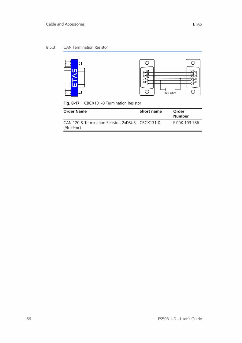
66
Cable and Accessories ETAS
8.5.3 CAN Termination Resistor
Fig. 8-17 CBCX131-0 Termination Resistor
Order Name Short name Order Number
CAN 120 & Termination Resistor, 2xDSUB (9fc+9mc)
CBCX131-0 F 00K 103 786
54321 6
7895
4321
9876
120 Ohm
ES593.1-D - User’s Guide
ETAS Ordering Information
9 Ordering Information
9.1 ES593.1-D
9.1.1 ES593.1-D with CBP120 Power Supply Cable
9.1.2 ES593.1-D with CBP1205 Power Supply Cable
Order Name Short Name Order Number
ES593.1-D Interface Module (1xETK, 2xCAN, 2xLIN, 2xFlexRay, 1xEthernet)
ES593.1-D F 00K 107 110
Package Contents
ES593.1-D Interface Module (1xETK, 2xCAN, 2xLIN, 2xFlexRay, 1xEthernet), Cable CBE100-3, CBP120-2, T-Bracket for Housing, ES523_CD, List "Content of this Package", QNX Licence with AP for ES5xx, ES5xx Premium Line Safety Advice, China-RoHS-leaflet_Compact_green_cn
Note
The cables for additional interfaces of the module are not part of the delivery scope and must be ordered separately (see chapter 9.2 on page 68).
Order Name Short Name Order Number
ES593.1-D Interface Module (1xETK, 2xCAN, 2xLIN, 2xFlexRay, 1xEthernet) with Safety Cable
ES593.1-D-S F 00K 110 424
Package Contents
ES593.1-D Interface Module (1xETK, 2xCAN, 2xLIN, 2xFlexRay, 1xEthernet), Cable CBE100-3, CBP1205-2, T-Bracket for Housing, ES523_CD, List "Content of this Package", QNX Licence with AP for ES5xx, ES5xx Premium Line Safety Advice, China-RoHS-leaflet_Compact_green_cn
Note
The cables for additional interfaces of the module are not part of the delivery scope and must be ordered separately (see chapter 9.2 on page 68).
ES593.1-D - User’s Guide 67

68
Ordering Information ETAS
9.2 Cable and Accessoires
9.2.1 Cable for the "7-29 V DC" Connection
9.2.2 "HOST" Interface Cable
9.2.3 "ETH1 and ETH2" Interface Cable
Ethernet Connection and Power Supply Cable
Note
Only use the ETAS cables named in this User’s Guide at the interfaces of the ES593.1-D. The maximum admissible cable lengths must be adhered to.
Note
Custom cables can be produced according to your specifications. For more information on custom cables, please contact your local ETAS sales representa-tive.
Order Name Short Name Order Number
Power Supply Cable, Lemo 1B FGJ Banana (2fc-2mc), 2 m
CBP120-2 F 00K 102 584
Power Supply Cable, Lemo 1B FGJ – Safety Banana (2fc-2mc), 2 m
CBP1205-2 F 00K 110 023
Order Name Short Name Order Number
Ethernet PC Connection Cable, Lemo 1B FGG - RJ45 (8mc-8mc), 3 m
CBE100-3 F 00K 102 559
Ethernet PC Connection Cable, Lemo 1B FGG - RJ45 (8mc-8mc), 8 m
CBE100-8 F 00K 102 571
Order Name Short Name Order Number
Ethernet Connection and Power Supply Cable, Lemo 1B FGF Lemo 1B FGD (8mc-8mc), 0m45
CBE130-0m45 F 00K 102 748
Ethernet Connection and Power Supply Cable, Lemo 1B FGF Lemo 1B FGD (8mc-8mc), 3 m
CBE130-3 F 00K 102 587
ES593.1-D - User’s Guide

ETAS Ordering Information
Ethernet Connection Cable
Ethernet Connection Adapter Cable
9.2.4 "ETK" Interface Cable
Ethernet Connection and Power Supply Cable with Angular Connectors, Lemo 1B FMF Lemo 1B FMD (8mc-8mc), 0m45
CBE140-0m45 F 00K 104 153
Ethernet Connection and Power Supply Cable, Lemo 1B FGF Lemo 1B FGL Banana (8mc-8fc+2mc), 3 m
CBEP420.1-3 F 00K 105 292
Ethernet Connection and Power Supply Cable, Lemo 1B FGF Lemo 1B FGL Banana (8mc-8fc+2mc), 3 m
CBEP425.1-3 F 00K 105 972
Order Name Short Name Order Number
Ethernet PC Connection Cable, Lemo 1B FGF Lemo 1B FGL (8mc-8fc), 3 m
CBE400.2-3 F00K 104 920
Ethernet PC Connection Cable, Highly Flex-ible, Lemo 1B FGF Lemo 1B FGL (8mc-8fc), 0m5
CBE401.1-0m5 F00K 106 128
Order Name Short Name Order Number
Ethernet Connection Adapter Cable 1 Gbit/s to 100 Mbit/s, Lemo 1B PHE - Lemo 1B FGF (10fc-8mc), 0m5
CBAE330-0m5 F00K 105 709
Order Name Short Name Order Number
ETK Interface Cable 100 Mbit/s, Lemo 1B FFG Lemo 1B FFG (4mc-4mc), 3 m
CBM150-3 F 00K 102 556
ETK Interface Cable 100 Mbit/s, Lemo 1B FFG Lemo 1B FFG (4mc-4mc), 5 m
CBM150-5 F 00K 102 557
ETK Interface Cable 100 Mbit/s, Lemo 1B FFG Lemo 1B FFG (4mc-4mc), 10 m
CBM150-10 F 00K 102 553
Order Name Short Name Order Number
ES593.1-D - User’s Guide 69

70
Ordering Information ETAS
9.2.5 "CAN/LIN" Interface Cable and Adapter
CAN Interface Cable
CAN Termination Resistor
9.2.6 Housing Accessories
9.2.7 Software
Order Name Short Name Order Number
CAN Interface Cable, OBDII J1962 Lemo 1B FGC (16mc-8mc), 2m5
CBAC150-2m5 F 00K 104 159
CAN Interface Cable, Lemo 1B FGC - Banana (8mc - 2mc), 1m5
CBAC160.1-1m5
F00K 106 116
CAN Interface Y-Cable, Lemo 1B FGC 2xD-SUB (8mc-9fc+9mc), 2 m
K106 F 00K 001 271
CAN Interface Y-Cable, Lemo 1B FGC Lemo 0S PCA Lemo 0S FFA (8mc,- 2fc+2mc) , 2 m
K107 F 00K 001 272
CAN, FlexRay and LIN Interface Y-Cable, Lemo 1B FGC - 2xDSUB (8mc-9fc+ 9mc), 2 m
CBCFI100-2 F 00K 106 893
Order Name Short Name Order Number
CAN 120 & Termination Resistor, 2xDSUB (9fc+9mc)
CBCX131-0 F 00K 103 786
Order Name Short Name Order Number
T-Bracket for ES600 Housing ES600_H_TB F 00K 001 925
Order Name Short Name Order Number
INCA ES5xx Software Integration Package for INCA V6.2.1 and later
ISW_ES5xx F 00K 106 641
ES593.1-D - User’s Guide

ES593.1-D - User’s Guide 71
ETAS ETAS Contact Addresses
10 ETAS Contact Addresses
ETAS HQ
ETAS GmbH
ETAS Subsidiaries and Technical Support
For details of your local sales office as well as your local technical support team and product hotlines, take a look at the ETAS website:
Borsigstraße 14 Phone: +49 711 3423-0
70469 Stuttgart Fax: +49 711 3423-2106
Germany WWW: www.etas.com
ETAS subsidiaries WWW: www.etas.com/en/contact.php
ETAS technical support WWW: www.etas.com/en/hotlines.php
ETAS Figures
Figures
Fig. 3-1 View of the Device...................................................................................... 12Fig. 3-2 Front Panel ................................................................................................. 14Fig. 3-3 Back Panel .................................................................................................. 14Fig. 3-4 Flash Codes ................................................................................................ 15Fig. 4-1 Block Diagram ............................................................................................ 19Fig. 5-1 Levering Off the Plastic Foot ....................................................................... 25Fig. 5-2 Tapped blind hole ..................................................................................... 26Fig. 5-3 Connecting the ES593.1-D to Another Module........................................... 27Fig. 5-4 ES593.1-D and ES595.1 with ES400 modules, XETK, ETK and vehicle buses 28Fig. 5-5 Example of a Module Network.................................................................... 30Fig. 7-1 WEEE Symbol ............................................................................................. 44Fig. 7-2 Power Supply Interface (7-29V) .................................................................. 50Fig. 7-3 Host Interface (HOST) ................................................................................ 50Fig. 7-4 Ethernet Interfaces (ETH1 and ETH2) .......................................................... 51Fig. 7-5 ETK Interface (ETK) .................................................................................... 51Fig. 7-6 CAN Interface (CAN1 and CAN3) ............................................................... 52Fig. 7-7 CAN Interface (CAN2 and CAN4) ............................................................... 52Fig. 8-1 Cable CBP120-2 (power supply cable with standard banana plugs)............. 54Fig. 8-2 Cable CBP1205 (power supply cable with safety banana plugs) .................. 55Fig. 8-3 CBE100-x Cable ......................................................................................... 56Fig. 8-4 CBE130-x Cable ......................................................................................... 56Fig. 8-5 CBE140-0m45 Cable ................................................................................. 57Fig. 8-6 CBEP420.1 Cable ....................................................................................... 57Fig. 8-7 CBEP425.1 Cable ....................................................................................... 58Fig. 8-8 CBE400.2 Cable ........................................................................................ 58Fig. 8-9 CBE401.1 Cable ........................................................................................ 59Fig. 8-10 CBAE330.2 Cable ...................................................................................... 59Fig. 8-11 CBM150-x Cable ....................................................................................... 60ES593.1-D - User’s Guide 72

73
Figures ETAS
Fig. 8-12 CBAC150-2m5 Cable ................................................................................ 61Fig. 8-13 CBAC160-1m5 Cable ................................................................................ 61Fig. 8-14 K106 Cable ............................................................................................... 62Fig. 8-15 K107 Cable ............................................................................................... 62Fig. 8-16 CBCFI100 Cable ........................................................................................ 63Fig. 8-17 CBCX131-0 Termination Resistor ............................................................... 66
ES593.1-D - User’s Guide
ETAS Index
Index
Symbols"Wake Up" Function 23"Wake-Up" Function 23“Wake Up” Function, configuring 32AAccident prevention 8Advanced Operating Mode 21Applications 28
Software Requirements 46
BBack Panel, Interfaces 14Basic Operating Mode 21Block Diagram 19Bus Terminating Resistor, CAN- 22
CCable
CBAC150-2m5 61CBAC160-1m5 61CBAE330.2 59CBCFI100 63CBE100-x 56CBE130-x 56CBE140-0m45 57CBE400.2 58CBE401.1 59CBEP420.1 57CBEP425.1 58CBM150-x 60CBP120-2 54
CBP1205 55K106 62K107 62
CAN Bus Terminating Resistor 22CAN Interface (CAN1/LIN1, CAN2/LIN2)22Carrier System 25Cascading Modules 20CE conformity declaration 44Clock Pulse 23Compatibility 47, 48Compatibility Operating Mode 21Connecting
Housing 26Cylinder Screw, M3 26
DData
Electrical 47Mechanical 44Technical 42
Documentation 8
EElectrical Data 47Electrical safety 9Error LEDs 33ETAS Contact Addresses 71ETAS Device Synchronization 23Ethernet Switch
Features 19
ES593.1-D - User’s Guide 74

75
Index ETAS
ETK interface 49, 51ETK Interface (ETK) 20ETK Interface Operating Mode
Advanced 21Basic 21Compatibility 21
FFeature 22Features 12
Ethernet Switch 19Firmware Update 24Flash Codes 15Front Panel, Interfaces 14Functional Description 19
GGetting Started 25
HHardware
System Requirements 45Hardware Description 12Housing 13
Connecting 26Fastening 25
HSP 24
IInitialization 21Interfaces 14Interfaces, Back Panel 14Interfaces, Front Panel 14
LLEDs 15Length of Engagement 26Link Signal Detector 23
MMechanical Data 44Module
Daisy-Chaining 26Module Network
Complex 30Example 30Simple 30
Module network 20
NNorms 43
OON 15, 16Operating Mode
Advanced 21
Basic 21Compatibility 21
Operating Modes 22ETK Interface 21
OperationConventions 7Use Case 6
Ordering Information 67
PPC network adapter 45Phase Shift 23Pin Assignment 50Plastic Foot 25Power Supply 19Power Supply of connected Modules20Presentation of information 6Product
Exclusion of liability 8Product Back 44
QQualification, required 8
RREACH regulation (EU) 45Receive Data 51Recycling 44RoHS conformity
China 44European Union 44
RX 51
SSafety at work 8, 9Safety notices
basic 8Identification 6
Safety precautions 8Scope of supply 7Screw Thread 25Send Data 51Standards 43Standards and Norms 43Supply Voltage 51SYNC-IN 23SYNC-OUT 23System Requirements 45
TT-Bracket 26Technical Data 42Termination Resistor
CBCX131-0 66
ES593.1-D - User’s Guide
ETAS Index
Time Synchronization Unit 23Troubleshooting 33TX 51
UUBATT 51Use, intended 8
WWaste Electrical and Electronic Equip-ment 44Web Interface 24WEEE 44WEEE take-back System 44Wiring 29
ES593.1-D - User’s Guide 76